
INTERNATIONAL CIVIL AVIATION ORGANIZATION ASIA … · version 3.0 – september 2007 international...
95
Version 3.0 – September 2007 INTERNATIONAL CIVIL AVIATION ORGANIZATION ASIA AND PACIFIC OFFICE ASIA/PACIFIC REGIONAL INTERFACE CONTROL DOCUMENT (ICD) FOR ATS INTERFACILITY DATA COMMUNICATIONS (AIDC) Version 3.0 - September 2007 Issued by the ICAO Asia/Pacific Regional Office, Bangkok
Transcript of INTERNATIONAL CIVIL AVIATION ORGANIZATION ASIA … · version 3.0 – september 2007 international...

Version 3.0 – September 2007
INTERNATIONAL CIVIL AVIATION ORGANIZATION ASIA AND PACIFIC OFFICE
ASIA/PACIFIC REGIONAL INTERFACE CONTROL DOCUMENT (ICD)
FOR ATS INTERFACILITY DATA COMMUNICATIONS (AIDC)
Version 3.0 - September 2007
Issued by the ICAO Asia/Pacific Regional Office, Bangkok

Asia/Pacific Regional ICD for AIDC
Version 3.0 – September 2007
i -1
TABLE OF CONTENTS 0. EXECUTIVE SUMMARY .......................................................................................................... 1 1. FOREWORD ................................................................................................................................. 2 1.1 Historical ............................................................................................................................ 2 2. THE DOCUMENT ....................................................................................................................... 4 2.1 Introduction........................................................................................................................ 4 2.2 Part I - Purpose, Policy and Units of Measurement ..................................................... 4 2.3 Part II - Communications and Support Mechanisms..................................................... 4 2.4 Appendices......................................................................................................................... 4 2.5 List of Acronyms ............................................................................................................... 4 PART I - PURPOSE, POLICY AND UNITS OF MEASUREMENT .................................... 7 1. PURPOSE ...................................................................................................................................... 7 2. SCOPE ............................................................................................................................................ 7 3. POLICY.......................................................................................................................................... 7 3.1 Document amendments ..................................................................................................... 7 3.2 System Philosophy............................................................................................................. 7 4. UNITS OF MEASUREMENT..................................................................................................... 8 4.1 Introduction........................................................................................................................ 8 4.2 Time and date..................................................................................................................... 8 4.3 Geographic position information....................................................................................... 8 4.4 Level and speed information ............................................................................................. 8 4.5 Offset and weather deviation information......................................................................... 9 5. RESTRICTION FORMATS...................................................................................................... 10 5.1 Level and speed restrictions ............................................................................................ 10 5.2 Time restrictions .............................................................................................................. 11 PART II - COMMUNICATIONS AND SUPPORT MECHANISMS .................................. 12 1. INTRODUCTION....................................................................................................................... 12 2. MESSAGE HEADERS, TIMERS AND ATSU INDICATORS ............................................ 12 2.1 Message Headers ............................................................................................................. 12 2.2 Timers............................................................................................................................... 13 2.3 ATSU Location Indicators............................................................................................... 14 3. ENGINEERING CONSIDERATIONS .................................................................................... 14 3.1 Future communications ................................................................................................... 14 3.2 ATN Transition Support.................................................................................................... 14 3.3 Performance criteria ................................................................................................................14 3.4 Recording of AIDC data .........................................................................................................14

Asia/Pacific Regional ICD for AIDC
Version 3.0 – September 2007
i -2
APPENDIX A - ATS COORDINATION MESSAGES ....................................................................A-1 1. INTRODUCTION.....................................................................................................................A-1 1.2 Coordination and the further route of flight..................................................................A-1 1.3 Field 3 requirements ......................................................................................................A-1 1.4 Field 7 requirements ......................................................................................................A-1 2. MESSAGE GROUP..................................................................................................................A-1 Table A-1 ASIA/PAC AIDC Messages ...........................................................................A-2 2.1 Notification messages....................................................................................................A-2 2.1.1 ABI (Advance Boundary Information) ...........................................................A-2 2.2 Coordination messages ..................................................................................................A-4 2.2.1 CPL (Current Flight Plan)................................................................................A-4 2.2.2 EST (Coordination Estimate)...........................................................................A-4 2.2.3 PAC (Preactivation)..........................................................................................A-5 2.2.4 MAC (Coordination Cancellation) ..................................................................A-5 2.2.5 CDN (Coordination) ........................................................................................A-6 2.2.6 ACP (Acceptance)............................................................................................A-7 2.2.7 REJ (Rejection) ................................................................................................A-7 2.2.8 TRU (Track Update) ........................................................................................A-8 2.3 Transfer of control messages.......................................................................................A-10 2.3.1 TOC (Transfer of Control) .............................................................................A-10 2.3.2 AOC (Assumption of Control) ......................................................................A-10 2.4 General information messages ....................................................................................A-10 2.4.1 EMG (Emergency).........................................................................................A-10 2.4.2 MIS (Miscellaneous)...................................................................................... A-11 2.4.3 TDM (Track Definition Message) ................................................................. A-11 2.5 Application Management Messages ...........................................................................A-13 2.5.1 LAM (Logical Acknowledgement Message) ................................................A-13 2.5.2 LRM (Logical Rejection Message) ...............................................................A-13 2.5.3 ASM (Application Status Monitor) ...............................................................A-15 2.5.4 FAN (FANS Application Message) ...............................................................A-15 2.5.5 FCN (FANS Completion Notification) .........................................................A-18 2.6 Surveillance Data Transfer Service Messages ............................................................A-19 2.6.1 ADS (Surveillance ADS-C)..........................................................................A-19 Table A-2 ASIA/PAC AIDC Messages and their Field Composition..........................A-21 APPENDIX B - ERROR CODES ........................................................................................................ B-1 1. INTRODUCTION..................................................................................................................... B-1 Table B-1 Error Codes .................................................................................................. B-1 APPENDIX C - ATM APPLICATION NAMING CONVENTIONS ..............................................C-1
Asia/Pacific Regional ICD for AIDC
Version 3.0 – September 2007
i -3
APPENDIX D - IMPLEMENTATION GUIDANCE MATERIAL .................................................D-1 1. INTRODUCTION.....................................................................................................................D-1 2. PRELIMINARIES ....................................................................................................................D-1 2.1 Assumptions...................................................................................................................D-1 2.2 AFTN Message Header .................................................................................................D-1 2.3 Response Messages .......................................................................................................D-2 2.3.1 Application Response ......................................................................................D-2 2.3.2 Operational Response ......................................................................................D-2 Table D-1. Required Operational Response .................................................................D-3 2.4 Application Management ..............................................................................................D-3 Table D-2. FCN Transmission .......................................................................................D-5 Figure D-1. Routine data link transfer using FAN and FCN messaging .....................D-6 Figure D-2. CPDLC Transfer using FAN and FCN messaging – initial
connection request failed ...............................................................................................D-7 Figure D-3. CPDLC Transfer using FAN and FCN messaging – unable to
establish CPDLC connection.........................................................................................D-8 Figure D-4. CPDLC Transfer using FAN and FCN messaging – initial
NDA not delivered..........................................................................................................D-9 3. PHASES OF FLIGHT .............................................................................................................D-9 3.1 Notification Phase..........................................................................................................D-9 3.2 Coordination Phase......................................................................................................D-10 3.3 Transfer of Control Phase............................................................................................D-13 4. FLIGHT STATE TRANSITIONS.........................................................................................D-13 4.1 Notifying States ...........................................................................................................D-13 4.2 Initial Coordination States ..........................................................................................D-13 4.3 Re-Negotiation States ................................................................................................D-14 4.4 Transfer States..............................................................................................................D-14 4.5 Backward Re-Negotiating State ................................................................................D-14 Table D-3 Flight States ................................................................................................D-14 Figure D-5. Flight State Transitions Diagram............................................................D-15 Table D-4. Flight State Transitions .............................................................................D-16 5. MESSAGE SEQUENCING ...................................................................................................D-17 Table D-5. Message Sequences ...................................................................................D-17 Table D-6. Valid Messages by ATSU...........................................................................D-18 6. OTHER MESSAGES .............................................................................................................D-19 6.1 General information messages ....................................................................................D-19 6.2 Surveillance data transfer messages ............................................................................D-19 7. EXAMPLES.............................................................................................................................D-20 7.1 Standard Coordination .................................................................................................D-21 7.2 Negotiation of Coordination conditions......................................................................D-21 7.3 Re-negotiation rejected................................................................................................D-21 7.4 Abbreviated Coordination ...........................................................................................D-22 7.5 Multiple notification + AIDC cancellation ...............................................................D-23 7.6 Multiple negotiations ...................................................................................................D-24 7.7 Standard coordination with proposed amended destination....................................D-24 7.8 Standard coordination including FAN/FCN exchange ...........................................D-25 7.9 Standard coordination with TRU update ................................................................D-26

Asia/Pacific Regional ICD for AIDC
Version 3.0 – September 2007
i -4
8. NOTES .....................................................................................................................................D-26 APPENDIX E - RELATIONSHIP TO ICAO AIDC MESSAGES................................................. E-1 Table E-1 ASIA/PAC AIDC/OPLINKP AIDC Relationship.......................................... E-2 APPENDIX F - INTERIM OPERATIONAL SUPPORT.................................................................F-1 1. INTRODUCTION......................................................................................................................F-1 2. INTERIM MESSAGES.............................................................................................................F-1 2.1 Estimate (EST) Message ................................................................................................F-1 APPENDIX G - TEMPLATES FOR BILATERAL LETTER OF AGREEMENT ON AIDC. G-1 Template 1: Generic Letter of Agreement ..........................................................................G-2 Template 2: Letter of Agreement - Auckland Oceanic - Brisbane ATS Centre ................G-5 Template 3: Memorandum of Understanding - Auckland Oceanic - Nadi ATM
Operations Centre ........................................................................................G-10

Asia/Pacific Regional ICD for AIDC
Version 3.0 - September 2007
1
Chapter 0 EXECUTIVE SUMMARY 0.1 The Asia/Pacific Regional Interface Control Document (ICD) for ATS Interfacility Data Communications (AIDC) is based on the work undertaken by the North Atlantic Systems Planning Group (NAT SPG) to standardise the interfacility message exchanges (ground/ground data link) needed to support oceanic automation in the North Atlantic Region. The NAT SPG agreed that the ground/ground data interchange should be in accordance with the procedures specified in a common ICD but that the common ICD should identify and detail any regional differences considered necessary. 0.2 The purpose of the ICD is to ensure that data interchange between units equipped with automated ATS systems used for air traffic management (ATM) in the ASIA/PAC Region is harmonised to a common base standard, and that the evolutionary development is coordinated and implemented centrally through the APANPIRG. Therefore, the ICD for the ASIA/PAC Region was developed to address any regional differences but, at the same time, preserve the common base standard set out in the Automatic Dependent Surveillance (ADS) Panel Guidance Material. 0.3 As in the North Atlantic, the ASIA/PAC Region has a great need for a communications and data interchange infrastructure that will significantly reduce the need for verbal coordination between Oceanic Area Control Centres and/or Area Control Centres. ATS Interfacility Data Communications (AIDC) standards, as defined in this document, provide the means by which data interchange between ATS units providing air traffic service in, and adjacent to, the ASIA/PAC Region is harmonised during the notification, coordination, and transfer of control phases of operations. 0.4 The message sets and procedures described in the ICD have been designed for use with the existing Aeronautical Fixed Telecommunications Network (AFTN) and the future Aeronautical Telecommunication Network (ATN). In the interest of global standardisation, ICAO agreed methods and messages were used wherever possible. Where ICAO methods and messages do not meet requirements, new messages were identified using existing ICAO field definitions to the extent possible. Specifically, the ICD defines the following:
(a) Basic communications and support required to coordinate implementation of AIDC throughout the ASIA/PAC Region;
(b) Common boundary agreements between all the area/oceanic control centres
concerned; (c) Implementation guidance material; and (d) Relationship to the ICAO OPLINKP (formerly the ADS Panel) AIDC message
set. 0.5 The ICD also describes a configuration management process which will ensure stability in the design and implementation of the messages described herein. As agreed, this process is applicable and adopted by Asia Pacific Provider States along with the ICD guidance material.

Asia/Pacific Regional ICD for AIDC
Version 3.0 – September 2007
2
Chapter 1 FOREWORD 1.1 HISTORICAL 1.1.1 In 1971, States in the North Atlantic (NAT) Region initiated action to begin the automation of flight data exchanges between Oceanic Area Control Centres (OACs) using On-Line Data-Interchange (OLDI) techniques. These techniques were not standard nor indeed even compatible, and it was agreed that to get full benefits from the application of OLDI, regional standardisation must be achieved. 1.1.1.1 OLDI was defined as system to system interchange of data with controller notification and presentation when necessary. It was not seen as a means where by controllers could effectively send and receive electronic mail. 1.1.2 At its twenty-fifth meeting (Paris, September 1988), the North Atlantic Systems Planning Group (NAT SPG) established a Task Force to develop a future ATS system concept for the whole of the NAT Region (NAT SPG/25, Conclusion 25/11 refers). 1.1.2.1 Today there are two types of OLDI in use, one known as European OLDI and the other known as NAT OLDI. The message sets differ to some degree with the European OLDI being simpler and oriented toward minimal controller interaction. The NAT OLDI message set includes messages which require manual intervention. 1.1.3 At its twenty-seventh meeting (Paris, June 1991), the NAT SPG noted that the draft ICD was sufficiently mature to be used for planning purposes and therefore agreed that States should endeavour to replace agreements that existed at the time with the common ICD by the end of 1991. Subsequent work within the NAT SPG upgraded the ICD to better match automation and communications transition requirements. 1.1.4 On the basis of the above, the ASIA/PAC Air Navigation Planning and Implementation Regional Group (APANPIRG), at its fifth meeting in 1994, undertook the task of developing the inter-facility message exchanges needed to support automation in the regions. 1.1.5 The ICAO OPLINK Panel then adopted the AIDC message set and included it as guidance material. 1.1.6 At the thirteenth meeting of APANPIRG (Bangkok, September 2002) decision 13/9 was made to reconvene the AIDC Task Force to undertake the reviewing and updating of the ASIA/PAC AIDC Interface Control Document (ICD).
1.1.7 The AIDC Review Task Force met in Brisbane on the 27th and 28th of March 2003. Discussions within the Task Force revealed inconsistencies between existing AIDC ICDs containing the same version number. The Task Force decided to baseline a document based on the original printed ICAO document. 1.1.8 As a result of this meeting the ASIA/PAC Regional ICD for AIDC was updated to include:
• Additional clarification of certain message types;
• Improved consistency of the terminology used in the document;
• Incorporation of recent changes proposed changes to PANS-ATM Doc. 4444 and
Doc. 9694, regarding additional optional sub-fields in ICAO Field 14; and

Asia/Pacific ICD for AIDC
Version 3.0 – September 2007
3
• Proposed additional message types, namely the Application Status Monitor (ASM), the FANS Application Notification (FAN) and the FANS Completion Notification (FCN).
1.1.9 Version 2.0 of the Asia/Pacific Regional ICD for AIDC was adopted by APANPIRG/14 in August 2003 under the Conclusion 14/3.
1.1.10 At the seventeenth meeting of APANPIRG (August 2006) Decision 17/13 was taken to reconvene the AIDC Task Force to complete the outstanding task of defining the format of the FAN message and addressing other outstanding issues identified in the ASIA/PAC AIDC Interface Control Document (ICD) Version 2.0.
1.1.11 The AIDC Task Force met in Bangkok 6-9 February, 2007.
1.1.12 As a result of this meeting, in addition to editorial changes, the ASIA/PAC Regional ICD for AIDC was updated to include:
a) specific error messages in Appendix B, Table B-1 associated with V2.0
functionality. b) clarification of some formats to avoid the possibility of differing
interpretations.
c) the format of the FANS message. d) modification of the format of the FCN message to permit greater flexibility in
its application.
e) the format of the ADS message.
f) the format and use of the TRU message.
1.1.13 Version 3.0 of the Asia/Pacific Regional ICD for AIDC was adopted by APANPIRG/18 in September 2007 under Conclusion 18/8.

Asia/Pacific Regional ICD for AIDC
Version 3.0 – September 2007
4
Chapter 2 THE DOCUMENT 2.1 INTRODUCTION 2.1.1 The ASIA/PAC Interface Control Document (ICD) for ATS Interfacility Data Communications is divided into the following Parts: 2.2 PART I - PURPOSE, POLICY AND UNITS OF MEASUREMENT 2.2.1 This part provides an overall philosophical view of the ICD, general information concerning the units that are used and information on data that is applicable to all ATSUs (Air Traffic Services Units). 2.3 PART II - COMMUNICATIONS AND SUPPORT MECHANISMS 2.3.1 This part describes the technical and other requirements needed to support AIDC. It also indicates that a longer term strategy for the transition to the ATN needs to be developed. 2.4 APPENDICES 2.4.1 Appendices include, inter alia, implementation guidelines which are relevant for software engineers, and a cross-reference to the ICAO OPLINKP AIDC message set, descriptions of messages used to exchange ATS data between automated ATS Systems, templates for typical bilateral letters of agreement when implementing AIDC, a list of error messages, and a Glossary of Terms. 2.5 LIST OF ACRONYMS
ABI Advance Boundary Information (AIDC message) ACARS Aircraft Communication Addressing and Reporting System ACC Area Control Centre ACI Area of Common Interest ACP Acceptance (AIDC message) ADS Surveillance ADS-C (AIDC message) ADS-B Automatic Dependent Surveillance - Broadcast ADS-C Automatic Dependent Surveillance - Contract AFN ATS Facilities Notification AFTN Aeronautical Fixed Telecommunications Network AIDC ATS Interfacility ASIA/PAC Data Communications AOC Airline Operational Control; or Assumption of Control
(AIDC message) AMHS ATS Message Handling System APANPIRG Asia/Pacific Air Navigation Planning and Implementation
Regional Group ARINC Aeronautical Radio Inc. ARTCC Air Route Traffic Control Center ASIA/PAC Asia/Pacific ASM Application Status Monitor (AIDC message) ATC Air Traffic Control ATSC Air Traffic Service Centre ATM Air Traffic Management ATMOC Air Traffic Management Operations Centre ATN Aeronautical Telecommunication Network ATS Air Traffic Services ATSU Air Traffic Service Unit C-ATSU Controlling ATSU CDN Coordination (AIDC message)

Asia/Pacific Regional ICD for AIDC
Version 3.0 – September 2007
5
CHG ICAO Modification Message CPDLC Controller Pilot Data Link Communications CPL Current Flight Plan (AIDC message) CRC Cyclic Redundancy Check D-ATSU Downstream ATSU DIA Coordination Dialogue EMG Emergency (AIDC message) EST Coordination Estimate (AIDC message) ETX End of Text FAN FANS Application Message (AIDC message) FANS (also FANS-1/A) Future Air Navigation System FCN FANS Completion Notification (AIDC message) FCO Facilities Notification Contact FI Flight Identifier FIR Flight Information Region FMC Flight Management Computer FMD Flight Management Computer (Selected) FMH Facilities Notification Message Header FML Flight Management Computer (Left) FMR Flight Management Computer (Right) FOM FANS Operations Manual FPL Filed Flight Plan FN_CAD Contact Advisory FPO Facilities Notification Current Position IA-5 International Alphabet 5 ICAO International Civil Aviation Organization ICD Interface Control Document IGM Implementation Guidance Material IMI Imbedded Message Identifier LAM Logical Acknowledgement Message (AIDC message) LOA Letter of Agreement LRM Logical Rejection Message (AIDC message) MAC Coordination Cancellation (AIDC message) MIS Miscellaneous (AIDC message) MTI Message Type Identifier NAT North Atlantic NDA Next Data Authority (CPDLC message); or
Next Data Authority (Next unit that will communicate with the aircraft using CPDLC)
OAC Oceanic Area Control Centre OCS Oceanic Control System ODF Optional Data Field OLDI On-Line Data-Interchange OPLINKP Operational Data Link Panel OSI Open System Inter-connection PAC Preactivation (AIDC message) PANS-ATM Procedures for Air Navigation Services - Air Traffic
Management REJ Rejection (AIDC message) R-ATSU Receiving ATSU RNP Required Navigation Performance SARPs Standards and Recommended Practices SITA Societe Internationale de Telecommunications
Aeronautiques SMI Standard Message Identifier

Asia/Pacific Regional ICD for AIDC
Version 3.0 – September 2007
6
SOH Start of Header STX Start of Text TCP Transfer of Control Point TDM Track Definition Message (AIDC message) TEI Text Element Identifier TOC Transfer of Control (AIDC message) TRU Track Update (AIDC message) UTC Universal Coordinated Time VSP Variable System Parameter

Asia/Pacific Regional ICD for AIDC
Version 3.0 – September 2007
7
PART I - PURPOSE, POLICY AND UNITS OF MEASUREMENT 1. PURPOSE 1.1 The purpose of the document is to ensure that data interchange between ATSUs providing air traffic services in, and adjacent to, the ASIA/PAC Region is harmonised to a common standard and to ensure that evolutionary development is encouraged and coordinated centrally. It also provides a description of the message types and methods of communication. 1.2 In the context of this document, the definition of AIDC is as follows: The AIDC application supports information exchanges between ATC application processes within automated ATS systems located at different ATSUs. This application supports the Notification, Coordination, and the Transfer of Communications and Control functions between these ATSUs. 1.3 In the interest of global standardisation, ICAO agreed methods and messages are used wherever possible. Where ICAO methods and messages do not meet requirements, new messages were identified using existing ICAO field definitions to the extent possible. 2. SCOPE 2.1 This document specifies the facilities and messages to be used within the ASIA/PAC region for the exchange of notification, coordination, transfer and related data between automated ATS systems. 2.2 The messages defined in this document are used during the various stages of the flight. Though outside the scope of the AIDC application, the Emergency, Flight Planning and Supplementary Message Categories as defined in ICAO Doc 4444 Appendix 3 will continue to be used to perform functions not provided by the AIDC application. 2.3 In particular, the Flight Planning function is required and will be required in the future to support operations within the ASIA/PAC Region. The ICAO messages FPL (Filed Flight Plan), CHG (Modification), DLA (Delay), DEP (Departure), ARR (Arrival), CNL (Cancel) and RQP (Request Flight Plan) will be used to support this function. 3. POLICY 3.1 Document amendment 3.1.1 Parts I and II of this ICD are under configuration control and are administered by the ICAO ASIA/PAC Regional Office in conjunction with APANPIRG. Changes to Parts I and II of the document shall only be made as a result of agreement by APANPIRG. Requested changes to the Appendices shall be relayed to the ICAO Regional Office in Bangkok, who will circulate requested proposed changes to all States in the Regions for comment and, subject to unanimous agreement, the Regional Office will amend such document accordingly. 3.2 System philosophy 3.2.1 The application of AIDC in the ASIA/PAC Region shall be based on a step-by-step data distribution scheme comprising three phases: Notification, Coordination and Transfer of Control. 3.2.1.1 The capability to revert to manual coordination shall be retained. 3.2.2 In support of all the operational phases, application management messages are required to support application level dialogue between automated ATS systems.

Asia/Pacific Regional ICD for AIDC
Version 3.0 – September 2007
8
3.2.3 Flight plans shall continue to be filed in accordance with existing procedures. 3.2.4 A functional address, which refers to a function within an OAC/ACC (e.g. an ATC watch supervisor), may be substituted in certain messages for the aircraft identification found in Field 7. Where such an address is used, it is preceded by an oblique stroke (/) to differentiate it from an aircraft identification. 4. UNITS OF MEASUREMENT 4.1 Introduction 4.1.1 In general the AIDC ICD messages support different units of measurement. Bilateral agreements should determine the units to be transmitted. 4.2 Time and date 4.2.1 All times shall be expressed in UTC as four digits, with midnight expressed as 0000. Dates, when used, shall be in the form of YYMMDD. 4.3 Geographic position information 4.3.1 Geographic position information shall be in accordance with the provisions contained in the Procedures for Air Navigation Services Air Traffic Management (PANS-ATM, Doc 4444). 4.4 Level and speed information 4.4.1 Level and speed information shall be specified in accordance with ICAO PANS-ATM Doc 4444 with the following exceptions applying only to Field 14 or the Track Data field in a TRU message. Note. When including more than one of the optional formats described below in the same AIDC message, the order that the data is incorporated into Field 14 is the order that it is described below. For example, if an AIDC message was to include a block level and an assigned Mach Number, the block level information would precede the Mach Number information. 4.4.1.1 Block level information 4.4.1.1.1 In certain circumstances, a vertical range of levels may be transmitted. Where a vertical range of levels is used, it shall be specified as a lower level followed by the upper level.
Example 1 MINNY/2125F320F340 The aircraft is operating in a block of levels between F320 and F340 (inclusive).
4.4.1.1.2 When transmitting a level restriction, only a single level may be included within the restriction.
Example 2 ELMER/0244F310F350F290A The aircraft is cleared to operate in a block of levels between F310 and F350 and will cross ELMER at or above F290.
4.4.1.1.3 The coordination of a vertical range of levels by AIDC should only be made following bilateral agreement. 4.4.1.2 Mach Number Technique information
4.4.1.2.1 The boundary estimate may contain additional clearance information describing a Mach Number that has been assigned to an aircraft. If transmitted, the Mach Number information

Asia/Pacific Regional ICD for AIDC
Version 3.0 – September 2007
9
shall always follow directly after the level information and be separated from the level information by a forward slash delimiter (/). This information shall contain:
• a single character providing advice as to whether an aircraft will be maintaining the notified Mach Number or less (L), the notified Mach Number or greater (G), or exactly the notified Mach Number (E); and
• four characters defining the notified Mach Number, expressed as the letter M
followed by 3 numerics.
Example1 BUGGS/0349F350F370/GM085 The aircraft is operating in a block of levels between F350 and F370 (inclusive) maintaining M0.85 or greater. Example 2 PLUTO/0215F310/EM076 The aircraft is maintaining M0.76.
4.4.1.2.2 The absence of speed information in the boundary estimate data of an AIDC message indicates that the previously assigned speed has been cancelled.
Example 3 SPEDY/1237F310F330B/LM083 The aircraft is cleared to F310 and will cross SPEDY at or below F330, maintaining M0.83 or less;
subsequently followed by: Example 4 SPEDY/1238F310 The aircraft will no longer be on descent at SPEDY, and has resumed normal speed (and one minute later than previously coordinated).
4.4.1.2.3 The format described for the notification and coordination of Mach Number in this section applies to Field 14 – boundary estimate data – only. It may be transmitted in any AIDC message containing Field 14.
4.4.1.2.4 The coordination of Mach Numbers by AIDC should only be made following bilateral agreement. 4.5 Offset and weather deviation information 4.5.1 The boundary estimate may contain additional clearance information describing an offset or weather deviation that has been issued to an aircraft. If transmitted, the offset and weather deviation information shall always be the last information in the group and shall be separated from preceding information by a forward slash delimiter (/). This information shall contain:
• a single character providing advice as to whether the clearance is an offset (O) or a weather deviation (W); and
• One to three characters indicating an off track distance associated with this
clearance (leading zeros shall not be used); and • a direction, indicating left (L), right (R) or either side of track (E).
Example 1 GOOFY/2330F310/GM084/O30R The aircraft is offsetting 30NM right of track, maintaining M0.84 or greater. Example 2 DAFFY/0215F310F350/W25E The aircraft is operating in a block of levels between F310 and F350 (inclusive) deviating up to 25NM either side of track.

Asia/Pacific Regional ICD for AIDC
Version 3.0 – September 2007
10
Example 3 DAFFY/0215F310F350/W5E The aircraft is operating in a block of levels between F310 and F350 (inclusive) deviating up to 5NM either side of track. Example 4 DAFFY/0215F310F350/W100E The aircraft is operating in a block of levels between F310 and F350 (inclusive) deviating up to 100NM either side of track.
4.5.2 The absence of offset or weather deviation data in the boundary estimate data of an AIDC message indicates that any previously notified or coordinated off track clearance no longer applies.
Example 5 MICKY/1519F330/W15R The aircraft is deviating up to 15NM right of track subsequently followed by: Example 6 MICKY/1520F330 The aircraft is back on track (and one minute later than previously coordinated).
4.5.3 The off-track clearance format described in this section applies only to Field 14 – boundary estimate data – or the Track Data field in a TRU message. It may be transmitted in a TRU message or any AIDC message containing Field 14.
4.5.4 When an aircraft is offsetting or deviating, the coordination point in the boundary estimate data shall be the coordination point based on the nominal route rather than any calculated boundary point based on the offset route.
4.5.5 When including Offset information in an AIDC message, the direction “E” (either side of track) shall not be used. 4.5.6 Valid “off track” distance values are integers between 1 and 250, with no leading zeros. The off track distance is measured in nautical miles (NM).
4.5. 7 The coordination of offsets and weather deviations by AIDC should only be made following bilateral agreement. 5. RESTRICTION FORMATS 5.1 Level and speed restrictions 5.1.1 Use of restrictions is not mandatory. If they are used the following convention shall be used. 5.1.2 Route, speed and level information contained in the Route field (ICAO ATS Field 15) represents the current cleared profile. Where a clearance requires a speed/level change subsequent to a route point, then the ICAO convention of route point followed by an oblique stroke and the new speed/level will be used (Ex. 1). Where a clearance requires a speed/level change to be completed by a route point, then the items will be reversed (Ex. 2). 5.1.3 A combination of these two conventions will describe a clearance with a defined starting and completion point (Ex. 3). Example 1 60N010W/M084F350 Example 2 M084F350/62N020W Example 3 60N010W/M084F350/62N020W

Asia/Pacific Regional ICD for AIDC
Version 3.0 – September 2007
11
5.2 Time restrictions 5.2.1 There are three types of time restrictions, describing when an aircraft should arrive at a fix: a) AT; b) AT OR BEFORE; or c) AT OR LATER. 5.2.2 A suffix will be added to the four digit time to denote the restriction type, as follows: a) AT: 'A', e.g. 1230A; b) AT OR BEFORE: 'B', e.g., 1230B; or c) AT OR LATER: 'L', e.g., 1230L. 5.2.3 The restriction itself will begin with a slash, i.e., '/', e.g., /1230B, and will appear after the fix with which it is associated. For example, 49N050W/1230L signifies that the aircraft should arrive at 49 N 50 W at or later than 1230 pm. 5.2.4 A time restriction may be used in conjunction with speed/level restrictions as follows: 60N010W/M084F350/1230L M084F350/62N020W/1230A 60N010W/M084F350/62N020W/1230B 5.2.5 Time restrictions may only appear in the Route field (Field 15). 5.2.6 The use of time restrictions shall be bilaterally agreed between ATS providers.

Asia/Pacific Regional ICD for AIDC
Version 3.0 – September 2007
12
PART II - COMMUNICATIONS AND SUPPORT MECHANISMS 1. INTRODUCTION 1.1 Coordination communications are divided into two areas; one addresses the need for voice communications between ATSUs whereas the other addresses the need for data communications. It is anticipated that the continuing implementation of automated data communications between ATSUs will result in a reduction in the utilisation of voice communications. 2. MESSAGE HEADERS, TIMERS AND ATSU INDICATORS 2.1 Message Headers 2.1.0 General. AFTN IA-5 Message Header, including the use of the Optional Data Field defined in Annex 10, Volume II and herein, will be employed for the exchange of all ATS data in the region. The AFTN priority indicator FF shall normally be used for all data exchanges. 2.1.1 Optional Data Field. The optional data field provides a flexible way to convey information on an end-to-end basis, undisturbed by the communication processes along the path. Since the information is optional it is necessary to specify a unique number and ending for each defined use. Option 1 has already been allocated for additional addressing use, and will be found in ICAO Annex 10, Volume II in due course. Option numbers 2 and 3 have been defined for computer applications to convey message/data unit identification and message/data unit reference information, respectively, and are adopted in this ICD. Other options can be defined and added as the need arises. The proposed encoding would have no impact on AFTN switching centers as they ignore this part of the origin line. 2.1.2 Addressing. The Source and Destination addresses of the AFTN header convey the direction and logical identity of the application processes exchanging AIDC information (data). The application process must be aware of the AFTN addresses that are used for this function. The first four characters form the location, while the next three characters specify an office/agency or a processor at the given location. The eighth character of the address indicates the end system application and details of the naming assignment are contained in Appendix C. This approach allows up to 26 multiple applications to be co-hosted in the same processor, each having its own unique address. This implementation will make the addressing consistent with Open System Inter-connection (OSI) parameters and simplify the transition to the ATN. 2.1.3 Message/Data Identification Number. The message/data identification number is a six (6) digit number, taken from a single application pool of available numbers. The identification of the sending and receiving units would use the normal 8-character addresses of the AFTN header. 2.1.3.1 The message/data identification number is encoded and conveyed in the AFTN message header Optional Data Field (ODF), option 2. The AFTN implementation provides functionality consistent with the OSI primitive/parameter structure. 2.1.3.2 A message/data identification number will be assigned to each message/data unit requiring confirmation of receipt by the initiating processor. This number will be assigned on an application process basis in such a way as to guarantee a unique identification number for a period of time as specified in paragraph 2.1.6. For messages/data not requiring confirmation the message/data identification parameter shall not be used. 2.1.4 Reference Information. The message/data reference information is a way of linking a message/data unit to a previously sent message. This function is encoded and conveyed in the AFTN ODF, option 3. This implementation would make the linking information consistent with the abstract OSI protocol primitive/parameter structure. The reference information consists of the message/data identification number of the previously sent message/data unit being referenced. As the previous message being referenced could have been originated by either processor the location indicator of the message source shall be used as a prefix to the reference number.

Asia/Pacific Regional ICD for AIDC
Version 3.0 – September 2007
13
2.1.5 Time Stamp. The time stamp is expressed as 12 digits in year, month, day, hours, minutes, and seconds (YYMMDDHHMMSS). The high precision (seconds) of the time stamp will support computation of transmission delays. This data item is conveyed as option 4 of the ODF. 2.1.6 Cyclic Redundancy Check (CRC). The CRC is a four digit hexadecimal number that is used to ensure end-to-end message integrity. The CRC employed is the CRC-CCITT. The CRC is computed over the message text, from the beginning left parenthesis to the closing right parenthesis, inclusive. Non printable characters such as line feeds and carriage returns shall be excluded from the CRC calculation. This data item is conveyed as option 5 of the ODF. 2.2 Timers 2.2.1 In order to guarantee the uniqueness of the message/data identification number, and yet allow for the efficient reuse of the numbers in the pool, two timers are required for each message/data unit requiring confirmation: accountability and reuse. 2.2.2 Accountability Timer. The accountability timer determines the maximum period of time for the responding application to confirm receipt of a given message/data unit. The default value for this timer nominally shall be three minutes. If there is no valid response from the responding application the initiating processor shall retransmit the message/data unit (and reset the timer), or initiate local recovery procedures. When local procedures allow retransmission a maximum value, such as three, must be determined before local recovery procedures are initiated. The accountability timer shall be cancelled by the receipt of any message with the appropriate message/data reference identifier, which will typically be a LAM or LRM. Retransmissions use the same message/data identification number as the original message/data unit. 2.2.3 Reuse Timer. The reuse timer function employs two timers that determine the minimum period of time during which a message/data identification number is guaranteed to be unique. Reuse timer A shall be set for exchanges not involving dialogues between processors. The range for reuse timer A shall be from 1 to 30 minutes, in one minute increments. The default value for reuse timer A shall be 5 minutes, or as agreed for communicating applications by the concerned administrations. Reuse timer B shall be set for exchanges where a dialogue is involved in the exchange. The range for reuse timer B shall be 2 to 90 minutes, in one minute increments. The default value for reuse timer B shall be 10 minutes, or as agreed for communicating applications by the concerned administrations. A given message/data identification number can be reused when an ACP, AOC, or REJ response message is received or the reuse timer has expired. 2.2.4 System Failure Timer Procedures. In the event of system failure the accountability and reuse timers will be reset and resume timing upon completion of system recovery. 2.2.5 Example. The following examples depict two ASIA/PAC Core Messages encoded in accordance with the previous procedures. The second message is a reference to the first message. SOH, STX, message ending and ETX characters are omitted for clarity, as are the alignment functions. FF NFFFZOZO 122145 KZOAZOZO 2.000033-4.940412214523-5.A34B- (CPL-UAL714-IS-B747/H-S/C-KLAX-05S179W/2220F370-M082F370(route data)-YSSY-0) Explanation: Sending an initial coordination message (number 000033 from Oakland (KZOAZOZO) to Nadi (NFFFZOZO) at time 940412 214523. FF KZOAZOZO 122147 NFFFZOZO 2.000044-3.KZOA000033-4.940412214703-5.DE6A- (ACP-UAL714-KLAX-YSSY)

Asia/Pacific Regional ICD for AIDC
Version 3.0 – September 2007
14
Explanation: Fiji (NFFFZOZO) accepts the proposed coordination condition received from Oakland (KZOAZOZO) by sending message number 000044 from NFFFZOZO to KZOAZOZO at 940412214703. The message refers to message 000033 sent earlier by KZOAZOZO 2.3 ATSU Location Indicators 2.3.1 ICAO location indicators must be used by automated ATSUs in AIDC messages. 3. ENGINEERING CONSIDERATIONS 3.1 Future Communications 3.1.1 The future data communications infrastructure should be compatible with the ICAO ATN. 3.1.2 Until the ATN becomes available, the engineering details needed to implement the exchange of messages contained in Appendix A will need to be agreed to bilaterally and identified in Appendix D. 3.2 ATN Transition Support 3.2.1 The AFTN will provide the underlying communications network and services within the ASIA/PAC region in the near-term. Communication services provided by the ground element of the ATN will be eventually employed by the AIDC application. 3.2.2 The APANPIRG ATN Implementation Coordination Group (ICG) is currently considering the continued use of AFTN format for AIDC application in the Asia/Pacific region. When the ATS Message Handling System (AMHS) has been implemented, the exchanges of AFTN messages on ATN can be accomplished using the AFTN/AMHS gateway function of the AMHS application. This mechanism can be used to exchange the AFTN AIDC messages providing that the connection has been tested to meet the recommended performance criteria in Appendix D. 3.2.3 The ASIA/PAC region will comply with ATN SARPs. A summary of these SARPs specifically relevant to ASIA/PAC operations, including addressing conventions and encoding rules, will be included within the document. 3.3 Performance Criteria 3.3.1 If AIDC messages are not transmitted and received in a timely manner between automation systems, aircraft can potentially cross boundaries without coordination or transfer of control responsibility taking place. The benefits of AIDC are also severely reduced if link speeds and transit times are inadequate. 3.3.2 In order to effectively use the AIDC application for the interchange of ATC coordination data, performance requirements need to be specified. These specified performance requirements need to be agreed to by neighbouring states implementing AIDC. Recommended performance figures are specified in Appendix D. 3.4 Recording of AIDC data 3.4.1 The contents and time stamps of all AIDC messages shall be recorded in both end systems in accordance with the current requirements for ATS messages. 3.4.2 Facilities shall be available for the retrieval and display of the recorded data.

Asia/Pacific Regional ICD for AIDC
Version 3.0 – September 2007
A-1
APPENDIX A - ATS COORDINATION MESSAGES 1. INTRODUCTION 1.1 The following sections describe those messages used by ASIA/PAC ATS systems for On-Line Data Interchange. These core messages are a selection from the AIDC message set developed by the ICAO OPLINK Panel. Unless otherwise indicated in this document, message fields will conform to ICAO field definitions (PANS-ATM Doc 4444), and are referred to by field number. All ATS data shall be enclosed between parentheses. Only one ATS message shall be included within a transmission. An overview of all ASIA/PAC core messages and their composition can be found in Table A-2. 1.2 Coordination and the further route of flight 1.2.1 Field 15 shall include subfields 15a, 15b and 15c. It shall describe the cleared route, beginning with the last significant point preceding the coordination point. It will contain all known cleared route information. As a minimum, it shall contain the first significant point in the adjacent ATSU’s airspace. If the cleared route of flight is not known completely to destination, the truncation indicator shall appear after the last known significant route point. For example:
1. M083F340 SALAG B333 PUGEL/M083F360 T 2. M083F300 DCT FICKY B200 TATAS T
Note 1: In accordance with PANS-ATM Doc 4444 the truncation indicator shall only follow a significant point or significant point/Cruising Speed and Cruising level in Field 15 and shall not follow an ATS route designator.
Note 2. ATSUs should be aware of the risks associated with simply deleting an unknown waypoint or route without using correct truncation procedures. Deletion of a waypoint or route will result in erroneous route information being transmitted to downstream ATSUs.
1.3 Field 3 Requirements 1.3.1 All messages shall use field 3a only.
1.3.2 Fields 3b and 3c are not used since, for AIDC, these reference numbers are included in the ODF, option 3. See Part 2, paragraph 2.1.4. 1.4 Field 7 Requirements 1.4.1 Where Field 7 is required to be present in a message, Field 7a (Aircraft Identification) shall be mandatory. Fields 7b (SSR Mode) and 7c (SSR Code) are optional but shall always be present where the information is available and applicable. 2. MESSAGE GROUP 2.0 The core messages shown in Table A-1 below are to be supported by all ASIA/PAC ATS Providers using automated data interchange. 2.0.1 Optional messages may be supported by ATS providers. Such messages will be detailed in bi-lateral agreements.

Asia/Pacific Regional ICD for AIDC
Version 3.0 – September 2007
A-2
Table A-1. ASIA/PAC AIDC Messages
Core Opt Message Class MessageX Notification ABI (Advance Boundary Information) X Coordination CPL (Current Flight Plan) X EST (Coordination Estimate) X MAC (Coordination Cancellation) X PAC (Preactivation)X CDN (Coordination)X ACP (Acceptance)X REJ (Rejection) X TRU (Track Update)X Transfer of Control TOC (Transfer of Control) X AOC (Assumption of Control) X General Information EMG (Emergency)X MIS (Miscellaneous) X TDM (Track Definition Message) X Application Management LAM (Logical Acknowledgement X LRM (Logical Rejection Message) X ASM (Application Status Monitor) X FAN (FANS Application Message) X FCN (FANS Completion Notification) X Surveillance Data Transfer ADS (Surveillance ADS-C)
2.1 Notification messages 2.1.1 ABI (ADVANCE BOUNDARY INFORMATION) 2.1.1.1 Purpose Used to give advance information on flights and shall be transmitted at a bilaterally agreed time or position (Variable System Parameter) before the common boundary. Changes to a previously transmitted ABI shall be communicated by means of another ABI. Changes to the cleared route of flight will result in the retransmission of an ABI. 2.1.1.2 Message Format ATS Field Description 3 Message type 7 Aircraft identification 13 Departure aerodrome 14 Boundary estimate data 16 Destination aerodrome 22 Amendment

Asia/Pacific Regional ICD for AIDC
Version 3.0 – September 2007
A-3
Field 22 shall contain as a minimum the following fields: 9 Number, type of aircraft and wake turbulence category 15 Route (see Appendix A, paragraph 1.2.1) Field 22 may also optionally include any or all of the following fields: 8 Flight rules 10 Equipment 18 Other information. Note that this field shall contain information as
received by the sending centre or a subset thereof as agreed between the parties
Subject to bilateral agreement, the following field may also be included in Field 22:
Text Amended Destination 2.1.1.3 Amended Destination is a free text field that may be used in the ABI message to notify an amended destination aerodrome. The field consists of an identifier (“DEST”) followed by a delimiter “/” character, followed by the name or the location of the new destination. When used, the Amended destination field is the last field within Field 22. 2.1.1.4 Example(s) (i) (ABI-THA179-EGLL-15N0090E/0700F330 -VTBD-8/IS-9/B747/H-10/S/C-15/14N093W 13N097W YAY T-18/0) (ii) (ABI-QFA43-YSSY-ESKEL/0300F330-NZAA-8/IS-9/B744/H-10/SIDHJRW/CD-
15/SY L521 ESKEL TANEN WN-DEST/NZWN) The second example shows an ABI following a diversion from the original destination (NZAA) to a new destination (NZWN). 2.1.2 More information concerning the usage of the Amended Destination field is contained in Appendix D – Implementation Guidance Material.

Asia/Pacific Regional ICD for AIDC
Version 3.0 – September 2007
A-4
2.2 Coordination messages 2.2.1 CPL (CURRENT FLIGHT PLAN) 2.2.1.1 Purpose Used to initiate initial coordination dialogue between automated ATS systems for a specific flight. 2.2.1.2 Message Format ATS Field Description 3 Message type 7 Aircraft identification 8 Flight rules 9 Aircraft type 10 Navigation equipment 13 Departure aerodrome 14 Boundary estimate data 15 Route (see Appendix A, paragraph 1.2.1) 16 Destination aerodrome 18 Other information 2.2.1.3 Example (CPL-QFA811-IS-B767/H-S/C-WSSS-20N070E/1417F350- M080F350 30N060E 40N090E YAY T-EGLL-0) 2.2.2 EST (COORDINATION ESTIMATE) 2.2.2.1 Purpose Used to inform the receiving centre of the crossing conditions for a flight and to indicate that the conditions are in compliance with agreements between the two parties. An ACP message shall be transmitted to complete the coordination process. The only valid response to an EST is an ACP. 2.2.2.2 Message Format ATS Field Description 3 Message type 7 Aircraft identification 13 Departure aerodrome 14 Boundary estimate data 16 Destination aerodrome 2.2.2.3 Example (EST-QFA811/A2277-WSSS-20N070E/1417F350-YAYT)

Asia/Pacific Regional ICD for AIDC
Version 3.0 – September 2007
A-5
2.2.3 PAC (PREACTIVATION) 2.2.3.1 Purpose Used to inform the receiving centre of the crossing conditions for a flight which has not yet departed and to indicate that the conditions are in compliance with agreements between the two parties. Normally it is only used when the departure point is close to the FIR boundary and preflight coordination is required. Note: On receipt of a PAC message an ACP message is required to be transmitted to complete the coordination process. The only valid response to a PAC is an ACP. 2.2.3.2 Message Format ATS Field Description 3 Message type 7 Aircraft identification 13 Departure aerodrome 14 Boundary estimate data 16 Destination aerodrome 22 Amendment (optional field) Field 22 may optionally include any or all of the following fields: 8 Flight rules 9 Number, type of aircraft and wake turbulence category 10 Equipment 15 Route (see Appendix A, paragraph 1.2.1)
18 Other information. Note that this field shall contain information as received by the sending centre or a subset thereof as agreed between the parties
2.2.3.3 Example (PAC-QFA811/A2277-WSSS-20N070E/1417F350-YAYT-10/S/C) 2.2.4 MAC (COORDINATION CANCELLATION) 2.2.4.1 Purpose Used specifically to indicate to a receiving centre that all notification and/or coordination received for a flight is no longer relevant to that centre. This message is not to be considered as a CNL message. 2.2.4.2 Message Format ATS Field Description 3 Message type 7 Aircraft identification 13 Departure aerodrome 16 Destination aerodrome 22 Amendment (optional field)

Asia/Pacific Regional ICD for AIDC
Version 3.0 – September 2007
A-6
Field 22 may only contain the following fields: 14 Boundary Estimate Data 18 Other Information Field 14 may be transmitted containing the boundary estimate data previously transmitted. It may be used if required, to correctly identify the flight concerned by the MAC, when appropriate. If a MAC is transmitted as a result of a diversion to a new destination (i.e. such that the receiving ATSU is no longer affected by the flight), Field 16 – Destination aerodrome – should contain the destination contained in the original Notification and/or coordination messages. 2.2.4.3 Examples
(i) (MAC-SIA286-NZAA-WSSS) (ii) (MAC-THA989-VTBD-YMML-18/RMK/DIVERTED TO YPDN) (iii) (MAC-FJI910-YSSY-NFFN-14/DUBEV/2330F370)
2.2.5 CDN (COORDINATION) 2.2.5.1 Purpose Used to propose changes to the coordination conditions agreed to in a previously transmitted CPL, EST, PAC or CDN message. Only one CDN dialogue can be active per flight at any given time between the same two ATSU’s (refer App D paragraph 3.2.5). The initial coordination dialogue is always terminated by an ACP message; otherwise a unit receiving a CDN can indicate that the coordination conditions should be left as previously agreed by transmitting an REJ message. CDN dialogues should be closed prior to the Transfer of Control occurring.
ATSUs should ensure that appropriate procedures are defined in bilateral Letters of Agreement for dealing with CDN messages containing a number of revisions (e.g. a revised estimate and level). There may be occasions when the receiving ATSU can accept one of the amendments but not the other. 2.2.5.2 Message Format ATS Field Description 3 Message type 7 Aircraft identification 13 Departure aerodrome 16 Destination aerodrome 22 Amendment Under normal circumstances, Field 22 may only contain fields 14, 15 and 18. Subject to bilateral agreement, the following fields may also be included in Field 22: 10 Equipment Text Amended Destination 2.2.5.3 Amended Destination is a free text field that may be used in the CDN message to propose the coordination of a new destination aerodrome. The field consists of an identifier (“DEST”) followed by a “/” character, followed by the name or the location of the new destination. When used, the Amended Destination field is the last field within Field 22.

Asia/Pacific Regional ICD for AIDC
Version 3.0 – September 2007
A-7
2.2.5.4 Examples ((ii)) (CDN-NWA36-NFFN-RJTT-14/20N150E/0446F370) (ii) (CDN-QFA1-YSSY-WSSS-10/SDGHIJRYZ/SD)
(iii) (CDN-KAL823-RJAA-NZCH-15/LTO G591 AA-DEST/NZAA) (iv) (CDN-MAPLE1-PKMJ-ZZZZ-14/MARTI/2200F310-15/MARTI 02N168E-
DEST/0150N16745E) 2.2.5.5 The last two examples demonstrate a CDN proposing a new route to an amended destination. In example (iii), there was no change to Field 14 – Boundary estimate data. Example (iv) shows a change of route with a corresponding change to Field 14. The “DEST/” included in Example (iv) refers to the proposed destination, rather than the original “ZZZZ” destination. Refer to Appendix D for the methodology in proposing a diversion to a new destination. 2.2.6 ACP (ACCEPTANCE) 2.2.6.1 Purpose Used to confirm that the contents of a received CPL, CDN, EST or PAC message are accepted. ACP messages may be generated automatically or manually. 2.2.6.2 Message Format ATS Field Description 3 Message type 7 Aircraft identification 13 Departure aerodrome 16 Destination aerodrome 2.2.6.3 Example (ACP-ACA860-NZAA-KSFO) 2.2.7 REJ (REJECTION) 2.2.7.1 Purpose Used to reject a clearance proposed by a CDN to a previously coordinated flight and terminate the coordination dialogue. The clearance remains as was previously agreed. 2.2.7.2 Message Format ATS Field Description 3 Message Type 7 Aircraft Identification 13 Departure Aerodrome 16 Destination Aerodrome 2.2.7.3 Example (REJ-AAL780-KSFO-RJAA)

Asia/Pacific Regional ICD for AIDC
Version 3.0 – September 2007
A-8
2.2.8 TRU (TRACK UPDATE) 2.2.8.1 Purpose Used to permit the coordination of amendments to previously agreed coordination conditions where prior coordination of these changes is not required. Because there is no operational response to the TRU message, use of this message must be in strict accordance with bilateral agreements between the ATSUs concerned. 2.2.8.2 Message Format ATS Field Description 3 Message type 7 Aircraft Identification 13 Departure Aerodrome 16 Destination Aerodrome Text Track Data 2.2.8.3 Track data is a free text field used in the TRU message to permit the transfer of updated clearance information from one ATSU to another. This field contains a number of elements which are described below. Each element consists of an “identifier” and a value which are separated by a “/” character. 2.2.8.4 All of the elements within the Track data field are optional, and multiple elements may be included, separated by a single <space> character. Track data will contain at least one element. When multiple elements are to be transmitted in a single TRU message, the order of the elements within the Track data field is the order in which they are listed below. Unused elements are not included in the Track data field. 2.2.8.5 Heading (HDG) This optional element is preceded by the identifier ‘HDG’ and contains the magnetic heading that has been assigned to the aircraft, expressed as a three digit number between 001 and 360. Example (i) HDG/080 2.2.8.6 Cleared Flight Level (CFL) This optional element is preceded by the identifier ‘CFL’ and contains the amended level that the aircraft has been assigned. Block levels in accordance with Part I paragraph 4.4.1.1 are also supported. Examples (i) CFL/F330 (ii) CFL/F310F330 2.2.8.7 Speed (SPD) This optional element is preceded by the identifier ‘SPD’ and contains details of the speed (Mach Number or Indicated airspeed) that the aircraft has been assigned.
• Mach numbers are expressed as “M” followed by 3 numerics giving the true Mach Number to the nearest .01 Mach.

Asia/Pacific Regional ICD for AIDC
Version 3.0 – September 2007
A-9
• Indicated airspeeds are expressed as “I” followed by 4 numerics giving the Indicated Airspeed in knots.
2.2.8.7.1 To cancel an assigned speed that had been previously coordinated, the SPD identifier is followed by a “/” character, followed by zero (0) Examples (i) SPD/M084 (ii) SPD/I0250 (iii) SPD/0 2.2.8.8 Direct to (DCT) This optional element is preceded by the identifier ‘DCT’ and contains the position that the aircraft has been cleared directly to. Examples (i) DCT/MICKY (ii) DCT/30S160E 2.2.8.9 Off Track deviation (OTD) This optional element is preceded by the identifier ‘OTD’ and contains the details of any off track clearance that has been issued to the aircraft. The format of the off track deviation is as described in Part I paragraph 4.5, i.e.
• a single character providing advice as to whether the clearance is an offset (O) or a weather deviation (W); and
• an off track distance associated with this clearance; • a direction, indicating left (L) or right (R) or, in the case of weather deviation, either
side of track (E); and • when including Offset information in an AIDC message, the direction “E” (either
side of track) shall not be used 2.2.8.9.1 To cancel a previously coordinated off track deviation, the OTD identifier is followed by a “/” character, followed by zero (0). Examples (i) OTD/W20R (ii) OTD/O30L (iii) OTD/0 2.2.8.10 Depending on automation, the receiving ATSU may automatically update their flight plan data, or simply display the message to the responsible controller. 2.2.8.11 Examples (i) (TRU-UAL73-NTAA-KLAX-CFL/F280 OTD/W20R) (ii) (TRU-QFA43-YSSY-NZAA-HDG/115 CFL/F270)

Asia/Pacific Regional ICD for AIDC
Version 3.0 – September 2007
A-10
2.3 Transfer of control messages 2.3.1 TOC (TRANSFER OF CONTROL) 2.3.1.1 Purpose Used to offer the receiving centre executive control of a flight. 2.3.1.2 Message Format ATS Field Description 3 Message type 7 Aircraft identification, 13 Departure aerodrome 16 Destination aerodrome 2.3.1.3 Example (i) (TOC-TAP451/A2217-YMML-NZCH) 2.3.2 AOC (ASSUMPTION OF CONTROL) 2.3.2.1 Purpose Sent in response to a TOC to indicate acceptance of executive control of a flight. 2.3.2.2 Message Format ATS Field Description 3 Message type 7 Aircraft identification 13 Departure aerodrome 16 Destination aerodrome 2.3.2.3 Example (i) (AOC-TAP451/A2217-NFFF-PHNL) 2.4 General information messages 2.4.1 EMG (EMERGENCY) 2.4.1.1 Purpose Used at the discretion of ATSUs when it is considered that the contents require immediate attention. Normally the information would be presented directly to the controller responsible for the flight or to the controller expecting to receive responsibility for the flight. When the message does not refer to a specific flight, a functional address shall be used and the information presented to the appropriate ATS position. Where such an address is used it is preceded by an oblique stroke (/) to differentiate it from an aircraft identification. The following are some examples of circumstances which could justify the use of an EMG message.

Asia/Pacific Regional ICD for AIDC
Version 3.0 – September 2007
A-11
a) Reports of emergency calls or emergency locator transmission reports. b) Messages concerning hi-jack or bomb warnings. c) Messages concerning serious illness or disturbance among passengers. d) Sudden alteration in flight profile due to technical or navigational failure. e) Communications failure 2.4.1.2 Message Format ATS Field Description 3 Message type 7 Aircraft identification or functional address 18 Other information 2.4.1.3 Examples (i) (EMG-UAL123-RMK/Free Text) (ii) (EMG-/ASUP-RMK/Free Text) 2.4.2 MIS (MISCELLANEOUS) 2.4.2.1 Purpose Used to transmit operational information which cannot be formatted to comply with any other message type and for plain language statements. Normally the information would be presented directly to the controller responsible for the flight or to the controller expecting to receive responsibility for the flight. When the message does not refer to a specific flight, a functional address shall be used and the information presented to the appropriate ATS position. Where such an address is used it is preceded by an oblique stroke (/) to differentiate it from an aircraft identification. 2.4.2.2 Message Format ATS Field Description 3 Message type 7 Aircraft identification or functional address 18 Other information 2.4.2.3 Examples (i) (MIS-NWA456-RMK/Free Text) (ii) (MIS-/ASUP-RMK/Free Text) 2.4.3 TDM (TRACK DEFINITION MESSAGE) 2.4.3.1 Purpose Used to distribute track information to affected Area Control Centres (ACCs) and Airline Operational Control Centres (AOCs) for flight planning. The message contains track definition and activity time periods.

Asia/Pacific Regional ICD for AIDC
Version 3.0 – September 2007
A-12
2.4.3.2 Message Format 1. Message Identifier. The message begins with a "(TDM " and ends with ")". Fields
within the message are separated by a space (i.e. " "). 2. Track Name. The track name consists of two fields. The first field is always TRK.
The second field is the track identifier. The track identifier consists of 1 to 4 alphanumeric characters.
3. General Information. Contains: (A) Date and time the track was generated and message number for that particular track
in YYMMDDHHMMNN format where NN represents the message number. The initial TDM date/time message number group will look like: 941006134501. Message numbers 02 to 99 indicate TDM amendments or revisions. Note that zero padding may be required to provide the correct number of digits.
(B) Track status - Blank field for initial message or "AMDT" for amendment. 4. Activity Time Interval. This field consists of two date/time pairs, separated by a
blank character, in the following format: YYMMDDHHMM YYMMDDHHMM The first date/time pair represents the track activation, while the second is the track
termination date/time. Example: 9410070300 9410071500. This example represents an activation date/time of October 7, 1994, at 0300 UTC and a
termination date/time of October 7, 1994 at 1500 UTC. 5. Track Waypoints. This field contains the set of waypoints defining the track from
the ingress fix to the egress fix. Waypoints are represented as latitude/longitude or named en route points. Waypoints are separated from each other by a blank space. Note that zero padding may be required. For example:
60N150W 60N160W, or NORML NUMMI, or FINGS 5405N13430W, etc. 6. Optional Fields (A) Level: This optional field will not be used in the Pacific operations since levels are
published in separate documents, eg. Pacific Ocean Supplements. However, the field will be retained for possible future use. If used in the future, track levels lists may be specified for the east and westbound directions of flight and a track levels list would contain the complete list of levels available on the track for the specified direction of flight. The levels would apply to all waypoints in the track waypoint list.
(B) Connecting routes (RTS): The RTS field is an optional field not normally used by
automated ATS systems. When used, it is located after the waypoint list (before the remarks field) and begins with the keyword "RTS/" at the beginning of a line. Each line of the RTS field contains a single connecting route (to the ingress fix or from the egress fix).
7. Remarks. The Remarks subfield is a free text field that can contain additional
comments. If there are no remarks a zero (0) is inserted as the only text. The remarks subfield begins with "RMK/".

Asia/Pacific Regional ICD for AIDC
Version 3.0 – September 2007
A-13
2.4.3.3 Examples 2.4.3.3.1 The following TDM describes a route connecting Honolulu and Japan and would look similar to: (TDM TRK A 940413124001 9404131900 9404140800 LILIA 27N170W 29N180E 31N170E 32N160E MASON RTS/ PHNL KEOLA2 LILIA MASON OTR15 SMOLT OTR16 SUNNS OTR20 LIBRA RJAA RMK/0) 2.4.3.3.2 The following TDM Revision describes a revision to the TDM shown in 2.4.3.3.1. (TDM TRK A 940413131502 AMDT 9404131900 9404140800 LILIA 27N170W 29N180E 30N170E 32N160E MASON RTS/ PHNL KEOLA2 LILIA MASON OTR15 SMOLT OTR16 SUNNS OTR20 LIBRA RJAA RMK/0) 2.4.3.3.3 In the example given in 2.4.3.3.2 above, the message number (as delineated by the last two digits of the message generation date/time group) indicates it as the second ("2") message for the track. This is followed by "AMDT" to signify the previous message has been amended. 2.5 Application Management Messages 2.5.1 LAM (LOGICAL ACKNOWLEDGEMENT MESSAGE) 2.5.1.1 Purpose Sent for each message (except for another LAM or LRM) that has been received, processed, found free of errors and, where relevant, is available for presentation to a control position. Non-receipt of an LAM may require local action. The message identifier and reference identifier are found in the message header, which is defined in Part II. 2.5.1.2 Message Format ATS Field Description 3 Message type 2.5.1.3 Example (LAM) 2.5.2 LRM (LOGICAL REJECTION MESSAGE) 2.5.2.1 Purpose Used to reject a message which contains invalid information. The message identifier and reference identifier are found in the message header, which is defined in Part II of this document. The LRM will identify the first field found that contains invalid information, if this field information is available.

Asia/Pacific Regional ICD for AIDC
Version 3.0 – September 2007
A-14
2.5.2.2 Message Format ATS Field Description 3 Message type 18 Other Information 2.5.2.3 Field 18 will only use the RMK/ sub-field. It will comprise an error code, supporting text and the field number in which the error occurred (where applicable). 2.5.2.4 The following format is used in the RMK/ sub-field of the LRM to report errors: <error code>/<field number>/<invalid text> 2.5.2.5 The <error code> shall contain the appropriate error code number from Appendix B, Table B-1. The error code is described using up to three numeric characters without leading zeros. When multiple errors are detected in an AIDC message, only a single LRM should be generated in response. This LRM would usually contain the error code of the first error detected. 2.5.2.6 The <field number> will contain the field number corresponding to the error code extracted from Table B-1. Where multiple field numbers are assigned to an error code only the first field number containing the error will be sent. Where no field number is referenced in Table B-1 the field number sub-field will be empty. The field number can be described using up to six alphanumeric characters. Note. Some ATSUs may not support non-numeric field numbers (e.g. “HEADER”). Whilst this is acceptable in order to preserve backwards compatibility with existing systems, the preferred implementation is for any non-numeric field numbers from Table B-1 to be supported within the LRM. 2.5.2.7 The <invalid text> field will contain the error text corresponding to the error code extracted from Table B-1 (not including any of ‘explanatory text’ that may have been included in Table B-1). If the specific error can be identified, it may optionally be appended to the Table B-1 error text. The invalid text field can contain up to 256 characters. Note. Some ATSUs may not include the error text from Table B-1 in the <invalid text> field of transmitted LRMs. Whilst this is acceptable in order to preserve backwards compatibility with existing systems, the preferred option is for the LRM <invalid text> field to at least contain the error text from Table B-1. 2.5.2.8 The following shows a number of LRM examples. Where more than one LRM format is shown, the format of the first one is the preferred option. 2.5.2.9 Examples
(i) (LRM-RMK/1/HEADER/INVALID SENDING UNIT) OR
(LRM-RMK/1/ /INVALID SENDING UNIT) (See Note following paragraph 2.5.2.6).
(ii) (LRM-RMK/17/16/INVALID AERODROME DESIGNATOR) OR
(LRM-RMK/17/16/) (See Note following paragraph 2.5.2.7).
(iii) (LRM-RMK/57//INVALID MESSAGE LENGTH)

Asia/Pacific Regional ICD for AIDC
Version 3.0 – September 2007
A-15
(iv) (LRM-RMK/27/15/ INVALID LAT/LON 130S165E) (The actual error “130S165E” may be optionally appended to the error text from Table B-1, see paragraph 2.5.2.7).
2.5.3 ASM (APPLICATION STATUS MONITOR) 2.5.3.1 Purpose Sent to an adjacent centre to confirm that the adjacent centre’s ATC application system is online. It is transmitted when no other application messages have been received within an adaptable time.
The periodic interval between transmissions of this message should be determined based on the needs of the operational environment. Typical values may be between 5 and 30 minutes. 2.5.3.2 Message Format
ATS Field Description 3 Message Type
2.5.3.3 Example
(ASM)
2.5.4 FAN (FANS APPLICATION MESSAGE) 2.5.4.1 Purpose Transmitted by one ATSU (generally the controlling ATSU) to another ATSU (generally the receiving ATSU) to provide the required information necessary to establish CPDLC and/or ADS-C connections with a FANS equipped aircraft. 2.5.4.2 Message Format ATS Field Description 3 Message type 7 Aircraft identification 13 Departure aerodrome 16 Destination aerodrome Text Application data as described below 2.5.4.2.1 Receipt or transmission of a FAN message does not change the Coordination state of the flight. 2.5.4.3 Application data field Application data is a free text field used in the FAN message to permit the transfer of FANS logon information from one ATSU to another. This field contains a number of elements which are described below. Each element consists of an “identifier” and a value which are separated by a “/” character. The abbreviation used for the identifier corresponds to the associated ICAO abbreviation (where one exists); otherwise the three character MTI (Message Type Identifier) contained in the logon is used (refer to ARINC 622 for a listing of various MTIs).

Asia/Pacific Regional ICD for AIDC
Version 3.0 – September 2007
A-16
2.5.4.3.1 The order of the elements within the FAN message is the order that they are listed below, with consecutive elements being separated by a single <space> character. Although some elements within the Application data field may be “optional”, they should be included if the corresponding data is available (i.e. if the ATSU transmitting the FAN message has received this information either from a logon or a FAN message). This is for the benefit of downstream ATSUs that may use the information within these optional elements. If data is not available for an optional element, that element is not to be included in the FAN message. 2.5.4.3.2 Additional information concerning the elements described below is contained in Appendix D. 2.5.4.4 Standard message identifier (SMI) This mandatory element is preceded by the identifier ‘SMI’, and contains information relating to the address to which uplink messages are routed to in the avionics. The value of the SMI sent in the FAN message is the downlink SMI as it was received in either the most recently received logon or FAN message.
• Allowable values for the SMI are listed in ARINC 620. Examples of SMIs include “FML”, “FMR”, “FMD”, “FM3” and “AFD”.
Example SMI/FMD
2.5.4.5 Aircraft identification This mandatory element is preceded by the identifier ‘FMH’, and contains the aircraft identification as it was received in either the most recently received logon or FAN message.
Example FMH/MAS123
2.5.4.6 Aircraft registration This mandatory element is preceded by the identifier ‘REG’, and contains the registration details of the aircraft – including the hyphen if applicable - as it was received in either the most recently received logon or FAN message.
Examples (i) REG/N12345 (ii) REG/9V-ABC
2.5.4.7 Aircraft Address (ICAO 24 bit code) This optional element is preceded by the identifier ‘CODE’, and contains the six character hexadecimal translation of the 24 bit aircraft address as it was received in either the most recently received logon or FAN message.
Example CODE/ABC123
2.5.4.8 Aircraft position information This optional element is preceded by the identifier ‘FPO’, and contains the position of the aircraft as determined by the ATSU at the time of transmission of the FAN message, if this information is

Asia/Pacific Regional ICD for AIDC
Version 3.0 – September 2007
A-17
available. The position of the aircraft is expressed as a latitude/longitude in either dd[NS]ddd[EW] or ddmm[NS]dddmm[EW] format.
Examples (i) FPO/23S150E (ii) FPO/0823N11025E
2.5.4.9 ATS Application and Version Number There will usually be multiple elements associated with the ATS Application and Version number (i.e. CPDLC and ADS-C). Occurrences of this element are preceded by the identifier ‘FCO’, which describes the ATS data link application(s) available in the avionics, as they were received in a logon or a previously received FAN message. The FAN message must include at least one ATS data link application - a separate identifier is used for each available application. These elements may be transmitted in any order. 2.5.4.9.1 The value associated with the FCO identifier consists of three letters to describe the application name immediately followed by (i.e. with no intervening spaces) two numeric characters to represent the associated version number. Possible values for the 3 letters are “ATC” (for CPDLC) or “ADS” (for ADS-C), and the possible range of version numbers is 01 to 99.
Examples (i) FCO/ATC01 FCO/ADS01 (ii) FCO/ADS01
2.5.4.9.2 The second example illustrates a FAN message with the ADS-C application only. This may be either because the aircraft is not CPDLC equipped, or because the FAN is being used with an adjacent ATSU to enable monitoring using ADS-C by that ATSU when the aircraft is only entering the ACI. 2.5.4.10 Examples
(i) (FAN-QFA43-YSSY-NZAA-SMI/AFD FMH/QFA43 REG/VH-OJA FPO/34S158E FCO/ATC01 FCO/ADS01)
(ii) (FAN-ANZ123-NZAA-KLAX-SMI/FML FMH/ANZ123 REG/ZK-NJP
FCO/ADS01)
(iii) (FAN-SIA221-WSSS-YSSY-SMI/FMD FMH/SIA221 REG/9M-MRP CODE/A254B3 FPO/1214S11223E FCO/ATC01 FCO/ADS01)
2.5.4.11 ATSUs should ensure that at least two of the ACID, REG, or CODE fields are used to ensure that the logon information contained in the FAN message is associated with the correct flight data record. Note 1. If the FAN message contains information for the purpose of the next unit establishing a CPDLC connection, it should not be sent until after an appropriate CPDLC Next Data Authority message (NDA) has been transmitted to the aircraft, allowing a reasonable time for delivery of the NDA message. Note 2. Where an aircraft enters an adjacent ATSU’s ACI but does not actually enter the ATSU’s airspace and a FAN message is sent to the adjacent ATSU to enable monitoring using ADS-C then the FCO identifier for the CPDLC application should not be included.

Asia/Pacific Regional ICD for AIDC
Version 3.0 – September 2007
A-18
2.5.5 FCN (FANS COMPLETION NOTIFICATION) 2.5.5.1 Purpose The FCN may be transmitted by either the transferring or receiving ATSU to provide information concerning the CPDLC Connection status of the aircraft. It is transmitted by the transferring ATSU when their CPDLC Connection with the aircraft is terminated, providing notification to the receiving ATSU that they are the CPDLC Current Data Authority. It may also be transmitted by the receiving ATSU to provide notification of the establishment of a CPDLC Connection or the failure of a CPDLC Connection request. 2.5.5.1.1 Receipt or transmission of an FCN message does not change the Coordination state of the flight. 2.5.5.1.2 An FCN transmitted by the receiving ATSU may also (optionally) include contact/monitor frequency information to be issued to the aircraft by the transferring ATSU. 2.5.5.2 Message Format ATS Field Description 3 Message type 7 Aircraft identification 13 Departure aerodrome 16 Destination aerodrome Text Communication Status as described below 2.5.5.3 Communication Status field Communication Status is a free text field used in the FCN message to permit the transfer of CPDLC Connection status and (optionally) frequency information from one ATSU to another. This field may contain a number of elements which are described below. Each element consists of an “identifier” and a value which are separated by a “/” character. Separate elements are separated by a single <space> character. 2.5.5.4 CPDLC Connection Status identifier (CPD) 2.5.5.4.1 This mandatory element is preceded by the identifier “CPD”, and contains a single integer value which is used to provide information concerning an aircraft’s CPDLC Connection status. The value to be included in the CPDLC Connection Status field is determined from the following table.
CPDLC Connection Status FCN sent by transferring ATSU
FCN sent by receiving ATSU
Meaning
0 The CPDLC Connection with the aircraft has been terminated
0 No CPDLC Connection could be established with the aircraft
1 The CPDLC Connection Request failed due to the receiving ATSU not being the nominated CPDLC Next Data Authority
2 A CPDLC Connection has been established with the aircraft

Asia/Pacific Regional ICD for AIDC
Version 3.0 – September 2007
A-19
2.5.5.6 Frequency identifier (FREQ) 2.5.5.6.1 This optional element is preceded by the identifier “FREQ”, and may be included in an FCN message transmitted by the receiving ATSU to advise of any changes to a previously notified (or a default) frequency. The FREQ/ identifier provides advice to the transferring ATSU of the voice frequency to be transmitted to the aircraft in the CPDLC Contact/Monitor instruction. If no frequency information is to be transmitted this element should not be included in the FCN message. 2.5.5.6.3 When transmitted in the FCN message, the frequency variable does not contain units, spaces or leading zeroes. It may be up to 7 characters in length, containing integers or a decimal point selected from the frequency range below.
Range Units HF 2850 to 28000 kHz
VHF 117.975 to 137.000 MHz UHF 225.000 to 399.975 MHz
2.5.5.7 Examples 2.5.5.7.1 FCN transmitted by receiving ATSU:
(i) (FCN-SIA221-YSSY-WSSS-CPD/0) The CPDLC Connection request for SIA221 failed
(ii) (FCN-ANZ15-KLAX-NZAA-CPD/2 FREQ/13261) The CPDLC Connection request for ANZ15 was successful. Contact/Monitor voice frequency is 13261
2.5.5.7.2 FCN transmitted by transferring ATSU:
(i) (FCN-QFA43-YSSY-NZAA-CPD/0) The CPDLC Connection with QFA43 has been terminated 2.6 Surveillance Data Transfer Service Messages 2.6.1 ADS (SURVEILLANCE ADS-C) 2.6.1.1 Purpose Used to transfer information contained in an ADS-C report from one ATSU to another. 2.6.1.2 Message Format ATS Field Description 3 Message type 7 Aircraft Identification 13 Departure Aerodrome 16 Destination Aerodrome Text ADS-C Data

Asia/Pacific Regional ICD for AIDC
Version 3.0 – September 2007
A-20
2.6.1.3 ADS-C data field ADS-C data is a free text field used in the ADS message to permit the transfer of information contained in an ADS-C report from one ATSU to another. The data field consists of an identifier (“ADS”) followed by a delimiter “/” character, followed by a text string containing specific text extracted from the encoded ACARS ADS-C report received from the aircraft. 2.6.1.3.1 The data field may also be used to indicate that no further ADS messages will be sent to the receiving ATSU for the flight. To indicate this state the ADS identifier is followed by a delimiter “/” character, followed by a “0” (zero). The trigger would be by bilateral agreement (e.g. an ADS-C report has been received that places the aircraft outside the ACI and the predicted route group indicates that the aircraft will not re-enter the ACI). 2.6.1.3.2 The specific text to be included in the AIDC ADS message is described in Appendix D – Implementation Guidance Material. 2.6.1.4 Examples
(i) (ADS-ANZ90-RJAA-NZAA-ADS/.ZK-OKC030007FF946B6F6DC8FC044
B9D0DFC013B80DA88FC0A64F9E4438B4AC8FC000E34D0EDC00010140F3E86)
(ii) (ADS-ANZ90-RJAA-NZAA-ADS/0)

Asia/Pacific Regional ICD for AIDC A-21
Version 3.0 – September 2007
Table A-2. ASIA/PAC Core Messages
CORE OPT MESSAGE MESSAGE ACRONYM ICAO FIELDS NON-ICAO
FIELD 3 7 8 9 10 13 14 15 16 18 22
X Advance Boundary Information ABI
X X X X X X
8, 9, 10, 15, 18, Text
X Current Flight Plan CPL X X X X X X X X X X
X Coordination Estimate EST X X X X X
X Coordination Cancellation MAC
X X X X X
14,18
X PreActivation PAC
X X X X X X
8,9,10,15,18
X Coordination CDN
X X X X X
10,14,15,18, Text
X Acceptance ACP X X X X
X Rejection REJ X X X X
X Track Update TRU X X X X X
X Transfer of Control TOC X X X X
X Assumption of Control AOC X X X X

A-22 Asia/Pacific Regional ICD for AIDC
Version 3.0 – September 2007
CORE OPT MESSAGE MESSAGE ACRONYM ICAO FIELDS NON-ICAO
FIELD 3 7 8 9 10 13 14 15 16 18 22
X Emergency EMG X X X
X Miscellaneous MIS X X X
X Track Definition Message TDM X X
X Logical Acknowledgment Message LAM X
X Logical Rejection Message LRM X X
X Application Status Monitor ASM X
X FANS Application Message FAN X X X X X
X FANS Completion Notification FCN X X X X X
X Surveillance ADS-C ADS X X X X X
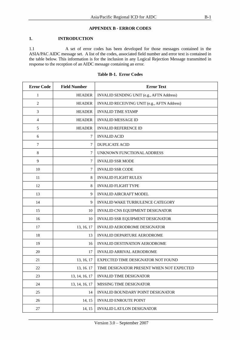
Asia/Pacific Regional ICD for AIDC
Version 3.0 – September 2007
B-1
APPENDIX B - ERROR CODES 1. INTRODUCTION 1.1 A set of error codes has been developed for those messages contained in the ASIA/PAC AIDC message set. A list of the codes, associated field number and error text is contained in the table below. This information is for the inclusion in any Logical Rejection Message transmitted in response to the reception of an AIDC message containing an error.
Table B-1. Error Codes Error Code Field Number Error Text
1 HEADER INVALID SENDING UNIT (e.g., AFTN Address)
2 HEADER INVALID RECEIVING UNIT (e.g., AFTN Address)
3 HEADER INVALID TIME STAMP
4 HEADER INVALID MESSAGE ID
5 HEADER INVALID REFERENCE ID
6 7 INVALID ACID
7 7 DUPLICATE ACID
8 7 UNKNOWN FUNCTIONAL ADDRESS
9 7 INVALID SSR MODE
10 7 INVALID SSR CODE
11 8 INVALID FLIGHT RULES
12 8 INVALID FLIGHT TYPE
13 9 INVALID AIRCRAFT MODEL
14 9 INVALID WAKE TURBULENCE CATEGORY
15 10 INVALID CNS EQUIPMENT DESIGNATOR
16 10 INVALID SSR EQUIPMENT DESIGNATOR
17 13, 16, 17 INVALID AERODROME DESIGNATOR
18 13 INVALID DEPARTURE AERODROME
19 16 INVALID DESTINATION AERODROME
20 17 INVALID ARRIVAL AERODROME
21 13, 16, 17 EXPECTED TIME DESIGNATOR NOT FOUND
22 13, 16. 17 TIME DESIGNATOR PRESENT WHEN NOT EXPECTED
23 13, 14, 16, 17 INVALID TIME DESIGNATOR
24 13, 14, 16, 17 MISSING TIME DESIGNATOR
25 14 INVALID BOUNDARY POINT DESIGNATOR
26 14, 15 INVALID ENROUTE POINT
27 14, 15 INVALID LAT/LON DESIGNATOR

Asia/Pacific Regional ICD for AIDC
Version 3.0 – September 2007
B-2
Error Code Field Number Error Text
28 14, 15 INVALID NAVAID FIX
29 14, 15 INVALID LEVEL DESIGNATOR
30 14, 15 MISSING LEVEL DESIGNATOR
31 14 INVALID SUPPLEMENTARY CROSSING DATA
32 14 INVALID SUPPLEMENTARY CROSSING LEVEL
33 14 MISSING SUPPLEMENTARY CROSSING LEVEL
34 14 INVALID CROSSING CONDITION
35 14 MISSING CROSSING CONDITION
36 15 INVALID SPEED/LEVEL DESIGNATOR
37 15 MISSING SPEED/LEVEL DESIGNATOR
38 15 INVALID SPEED DESIGNATOR
39 15 MISSING SPEED DESIGNATOR
40 15 INVALID ROUTE ELEMENT DESIGNATOR
41 15 INVALID ATS ROUTE/SIGNIFICANT POINT DESIGNATOR
42 15 INVALID ATS ROUTE DESIGNATOR
43 15 INVALID SIGNIFICANT POINT DESIGNATOR
44 15 FLIGHT RULES INDICATOR DOES NOT FOLLOW SIGNIFICANT POINT
45 15 ADDITIONAL DATA FOLLOWS TRUNCATION INDICATOR
46 15 INCORRECT CRUISE CLIMB FORMAT
47 15 CONFLICTING DIRECTION
48 18 INVALID OTHER INFORMATION ELEMENT
49 19 INVALID SUPPLEMENTARY INFORMATION ELEMENT
50 22 INVALID AMENDMENT FIELD DATA
51 MISSING FIELD nn (See Note 2)
52 MORE THAN ONE FIELD MISSING
53 MESSAGE LOGICALLY TOO LONG
54 SYNTAX ERROR IN FIELD nn (See Note 2)
55 INVALID MESSAGE LENGTH
56 TDM ERROR
57 INVALID MESSAGE
58 MISSING PARENTHESIS
59 MESSAGE NOT APPLICABLE TO zzzz OAC
60 3 INVALID MESSAGE MNEMONIC (i.e., 3 LETTER IDENTIFIER)

Asia/Pacific Regional ICD for AIDC
Version 3.0 – September 2007
B-3
Error Code Field Number Error Text
61 HEADER INVALID CRC
62 UNDEFINED ERROR
63 MSG SEQUENCE ERROR: ABI IGNORED
64 MSG SEQUENCE ERROR: INITIAL COORDINATION NOT PERFORMED
65 MSG SEQUENCE ERROR: EXPECTING MSG xxx; RECEIVED MSG yyy (See Note 2)
66 14 INVALID BLOCK LEVEL
67 14 INVALID OFF-TRACK CLEARANCE TYPE
68 14 INVALID OFF-TRACK DIRECTION
69 14 INVALID OFF-TRACK DISTANCE
70 14 INVALID MACH NUMBER QUALIFIER
71 14 INVALID MACH NUMBER
72 ADF (See Note 3) INVALID IDENTIFIER
73 ADF (See Note 3) INVALID SMI
74 ADF (See Note 3) INVALID ACID IN FMH/ IDENTIFIER
75 ADF (See Note 3) INVALID REGISTRATION IN REG/ IDENTIFIER
76 ADF (See Note 3) INVALID AIRCRAFT ADDRESS IN CODE/ IDENTIFIER
77 ADF (See Note 3) INVALID LOCATION IN FPO/ IDENTIFIER
78 ADF (See Note 3) INVALID DATA LINK APPLICATION IN FCO/ IDENTIFIER
79 ADF (See Note 3) INVALID OR UNSUPPORTED CPDLC VERSION NUMBER
80 ADF (See Note 3) INVALID OR UNSUPPORTED ADS-C VERSION NUMBER
81 ADF (See Note 3) INVALID IDENTIFIER IN FAN MESSAGE
82 CSF (See Note 4) INVALID CPDLC CONNECTION STATUS
83 CSF (See Note 4) INVALID FREQUENCY IN FREQ/ IDENTIFIER
84 ADF (See Note 5) INVALID IDENTIFIER IN ADS MESSAGE
85 ADF (See Note 5) INVALID DATA IN ADS MESSAGE Note. This error message refers to the encoded ADS-C data (e.g. if it contains non-hexadecimal characters), rather than whether the contents of the decoded ADS-C report itself are valid.
86 TDF (See Note 6) INVALID IDENTIFIER IN TRU MESSAGE
87 TDF (See Note 6) INVALID HEADING IN HDG/ IDENTIFIER
88 TDF (See Note 6) INVALID POSITION IN DCT/ IDENTIFIER
89 TDF (See Note 6) INVALID OFF TRACK DEVIATION IN OTD/ IDENTIFIER
90 TDF (See Note 6) INVALID FLIGHT LEVEL IN CFL/ IDENTIFIER
91 TDF (See Note 6) INVALID SPEED IN SPD/ IDENTIFIER
92-256 RESERVED FOR FUTURE USE

Asia/Pacific Regional ICD for AIDC
Version 3.0 – September 2007
B-4
Note 1. It is not intended that any amplifying text contained in parenthesis (i.e. “(e.g., AFTN Address)”) within the error text column be transmitted in any LRM. Note 2. The intention is that in error codes 51, 54, 59 and 65 that lower case text (e.g. “nn”, or “xxx”) is replaced by the applicable value when this information is available. Note 3. In the FAN message, the “ADF” field number refers to the Application data field Note 4. In the FCN message, the “CSF” field number refers to the Communication Status field Note 5. In the ADS message, the “ADF” field number refers to the ADS-C data field Note 6. In the TRU message, the “TDF” field number refers to the Track data field

Asia/Pacific Regional ICD for AIDC
Version 3.0 – September 2007
C-1
APPENDIX C - ATM APPLICATION NAMING CONVENTIONS 1. Eight character AFTN addresses will be used by the ASIA/PAC AIDC application to identify automated ATS end-systems. The first four characters identify the ATS unit location, while the last four characters identify an organization, end-system, or application process at the given location. 2. The table below describes a proposed naming convention, developed by the ATN Panel, for identifying ATM end-systems and applications. The last (eighth) character of the end-system's or application's AFTN address should be selected in accordance with the table.
8th character
ATM ground system application process
A Air space management
B Unassigned
C Unassigned
D Dynamic track generation
E Unassigned
F Flight data processing (processor routes to appropriate control sector based on internal configuration information.)
G Reserved for State use
H Reserved for State use
I Reserved for State use
J Reserved for State use
K Reserved for State use
L Reserved for State use
M OPMET data bank
N AIS data bank
O Oceanic data processing
P Unassigned
Q Unassigned
R Radar data processing (processor routes to appropriate control sector based on internal configuration information.)
S System management
T Air traffic flow management
U Unassigned
V Unassigned
W Unassigned
X Default value
Y Service function
Z Unassigned

Asia/Pacific Regional ICD for AIDC
Version 3.0 – September 2007
D-1
APPENDIX D - IMPLEMENTATION GUIDANCE MATERIAL 1. INTRODUCTION 1.1 The AIDC Message set described in Appendix A of the ASIA/PAC Regional Interface Control Document (ICD) for ATS Interfacility Data Communications supports six ATS-related functions: 1. Notification; 2. Coordination; 3. Transfer of Control; 4. General (Text) Information Interchange; 5. Surveillance Data Transfer; and 6. Application Management. 1.2 This appendix contains Implementation Guidance Material (IGM) of an explanatory nature. Information on how the message set as a whole is intended to be used is provided, with particular emphasis on the first three functions. The objective is to provide useful information and guidance to software engineers responsible for implementing the ASIA/PAC AIDC Message set within an automated ATS system. 1.3 Although outside the scope of the ICD, Flight Planning messages play an important role within the region, and will continue to do so in the future. 2. PRELIMINARIES 2.1 Assumptions 2.1.1 The following assumptions have been made: a) The IGM applies only to those portions of a flight operating within the
ASIA/PAC Regions; b) The material described below applies only to data transfers between two
automated ATS systems. Though most of it also applies to the general case of Notification and Coordination between more than two automated ATS systems, certain multi-ATSU Coordination problems have not yet been solved;
c) It must be possible to revert to manual intervention of the Notification,
Coordination, and Transfer of Control processes at any time; d) Exceptional conditions, such as loss of communications between two ATSUs,
are not addressed and are subject to local procedures; and e) An ATSU’s Area of Common Interest (ACI) is defined as the airspace for
which the ATSU is responsible, i.e., an FIR, and surrounding border regions just outside the FIR. These surrounding border regions are usually determined by the required separation minima.
2.2 AFTN Message Header 2.2.1 Every message transmitted shall contain an AFTN header, as specified in Part II of the ASIA/PAC ICD. This header shall contain the optional AFTN data fields described in Part II of the ASIA/PAC ICD.

Asia/Pacific Regional ICD for AIDC
Version 3.0 - September 2007
D-2
2.2.2 Message identifier numbers (AFTN optional data field 2) shall be sequential. Receipt of an out of sequence message shall result in a warning being issued. 2.2.3 A check for duplicate message identifier numbers shall be made. In general, since 1,000,000 numbers are available, no duplicates should be present. 2.2.4 Message identifier numbers shall begin at 0, proceed through 999,999, and then rollover to 0. The same sequence shall be repeated when necessary. 2.2.5 Each unique ATSU-to-ATSU interface shall select message identifier numbers from its own pool of numbers. Each pool shall encompass the entire possible range, i.e., include all numbers from 0 to 999,999. 2.3 Response Messages 2.3.1 Application Response 2.3.1.1 Every ASIA/PAC AIDC message received by an ATSU, except a LAM or LRM, shall be responded to with a LAM or LRM. While no LAM is generated for a valid LRM, an ATSU may choose to respond to an invalid LRM with an LRM. Such a response is termed an Application Response, and is generated automatically by the automation system. A LAM shall be transmitted when the receiving automation system found the received message to be syntactically correct and the message data was accepted for further processing or presentation. Otherwise, an LRM message shall be transmitted. 2.3.1.2 The timeout value Talarm associated with an application response shall be 180 seconds, corresponding to the nominal value associated with the accountability timer described in Part II, Section 2.2.2. 2.3.1.3 Failure to receive an expected application response (i.e. a LAM or LRM) within Tr seconds (≤Talarm) shall result in a re-transmission (up to a maximum number Nr) of the original message, using the same information contained in optional data fields 2 and 3 found in the original message header. The timeout timer Tr shall be reset upon re-transmission. Failure to receive an application response within Talarm seconds from the original transmission of the message shall result in a warning being issued. 2.3.1.4 The transmission of a LAM or LRM shall be triggered by the ATC application process, not the communications process. This is because an application response indicates that the received message was examined by the ATC application process(s), not just the communications functions. Note the distinction between an ATC application process, which implements a critical ATC function such as Coordination or Transfer of Control, and a communications process, which is responsible for the reliable delivery of data, but not data interpretation. This approach conforms to the OSI Reference Model. 2.3.1.5 Receipt of an LRM shall cause the receiving ATSU to take a corrective action before re-transmitting the message. This action may be automatic, as in a CRC error being indicated, or manual, as in an incorrect route element format. Once this action has been taken, the message shall be re-transmitted with a new message identifier number. 2.3.2. Operational Response 2.3.2.1 Several ASIA/PAC AIDC messages require a response, in addition to the normal application response, by another AIDC message. Such a response is termed an Operational Response. Table D-1 below indicates the required response to a received message. ASIA/PAC AIDC messages not listed in Table D-1 have no operational response.

Asia/Pacific Regional ICD for AIDC
Version 3.0 – September 2007
D-3
Table D-1. Required Operational Response
Received Message
Required Operational Response
CPL ACP or CDN EST ACP PAC ACP CDN ACP, CDN, or REJ TOC AOC
Note. An REJ is not available in an Initial Coordination Dialogue initiated by a CPL, EST or PAC. An REJ is only available in a CDN dialogue. 2.3.2.2 Failure to receive a response within an adapted operational response timeout period Top shall result in a warning being issued. 2.3.2.3 The value of Top is dependent on whether manual processing is required to generate the operational response. In general, Top should be less than 600 seconds when a manual action is required to trigger the operational response. 2.3.2.4 An operational response shall employ the AFTN header optional data field 3 to reference the original message being responded to. A coordination dialogue, which is initiated by one message and contains a sequence of message exchanges, until terminated by an ACP or REJ shall always reference the original message which triggered the dialogue. For example, one ATSU may initiate a coordination dialogue by transmitting a CPL message to an adjacent ATSU. A sequence of CDN messages may ensue, terminated by an ACP message. The CDN and ACP messages would all reference the original CPL message. After completion of the initial coordination dialogue in the preceeding example one ATSU may initiate another coordination dialogue by transmitting a CDN message. A sequence of CDN messages may ensue, terminated by an ACP message, Messages in this new coordination dialogue would reference the first CDN message in the dialogue. 2.4 Application Management 2.4.1 The ASM message is used to confirm that the ATC application on the other end is on-line. This message is sent by ATSU A to (adjacent) ATSU B if, after a mutually agreed time, no communication has been received from ATSU B. ATSU B responds, if the ATC application is active and functioning, by sending a LAM to ATSU A. If ATSU A does not receive a response LAM from ATSU B within a specified time, local contingency procedures should be executed. This message would normally be sent automatically, but may be sent manually for testing purposes.
2.4.2 The FAN message may be used to transfer a data link aircraft’s logon information from one ATSU to another. Implementation of this message removes the need to utilise the five step “Address Forwarding” process (initiated by the FN_CAD) that was developed for the initial implementation of FANS. The message contains all the information that is required to establish ADS-C and/or CPDLC connections with the aircraft. In the event that only an ADS-C connection will be required, the transferring ATSU should include ADS-C information only. If a FAN message is transmitted containing ADS-C information only, there should be no expectation of receiving an FCN (see below) response. If a FAN message is received containing ADS-C Application information only, there should be no attempt to establish a CPDLC connection. 2.4.3 Normally, one FAN message would be sent for each data link transfer per flight. However, when a FCN is received with a communication status field value of (1) indicating the receiving ATSU is not the Next Data Authority, the transferring ATSU should send another NDA message to the aircraft and another FAN message to the receiving ATSU to indicate that the NDA has been sent (refer Figure D-4). While the second FAN may not be required for address forwarding

Asia/Pacific Regional ICD for AIDC
Version 3.0 - September 2007
D-4
purposes it does provide the receiving ATSU with a positive indication that another NDA has been sent to the aircraft. 2.4.4 ATSUs implementing the FAN message should consider retaining existing Address Forwarding functionality to be used as a contingency for data link transfers in the event of failure of the ground-ground link. 2.4.5 Similarly to Address Forwarding, the FAN message should be sent at a time parameter prior to the boundary with the next ATSU. This parameter should be in accordance with guidance outlined in the FANS Operations Manual (FOM). Functionality for the transmission of a FAN message manually by the ATS officer should also be implemented. 2.4.6 Information concerning the identity of the aircraft (i.e. aircraft identification, aircraft address and registration) contained in the Application data field must not be extracted from the flight plan – it must be information that was contained in either the most recently received logon or FAN message. Note. This requirement only applies to the aircraft identification within the Application data field of the FAN message. The aircraft identification (i.e. ATS Field 7) at the beginning of the FAN message is the identification of the aircraft from the ATS flight plan. 2.4.6.1 When extracting the identity of the aircraft from the logon, the information required is the aircraft identification within the CRC protected portion of the logon – not the flight identifier (FI) that is contained in Line 4 of the ACARS logon message. In the example below, the aircraft identification is QFA924, rather than the QF0924 contained in Line 4 of the ACARS message.
QU BNECAYA .QXSXMXS 010019 AFD FI QF0924/AN VH-EBA DT QXT POR1 010019 J59A - AFN/FMHQFA924,.VH-EBA,,001902/FPOS33373E150484, 0/FCOADS,01/FCOATC,01292B
2.4.7 Under certain circumstances (e.g. FMC failure) it is possible for the SMI of an aircraft to change in flight, which will require a new logon from the aircraft to permit data link services to continue. To ensure that the next ATSU has up to date information, the SMI transmitted in any FAN message should be the SMI from the most recently received logon or FAN message. 2.4.8 A hyphen within the registration that was contained in either the logon or any previously received FAN message must also be included in the REG element of any transmitted FAN message. Without this hyphen, data link messages transmitted by the ATSU may not be delivered to the aircraft. Note. ATSUs implementing the FAN message must be aware of the possible existence of this hyphen within the registration, and that it does not signify a “new field” as is the case with other AIDC messages. 2.4.8.1 Any “padding” in the registration in the logon (e.g. preceding periods < . >s) must not be included in the FAN message. In the sample ACARS message above, the registration to be included in the FAN message would be “VH-EBA”, not “.VH-EBA”. 2.4.9 Some ATSUs may utilise the aircraft position which is an optional field that may be contained in the logon. If the aircraft position information element is to be included in any transmitted FAN message, there is little purpose in simply relaying the aircraft position from the original logon – the calculated position of the aircraft should be used instead.

Asia/Pacific Regional ICD for AIDC
Version 3.0 – September 2007
D-5
2.4.10 The FCN message, where used, provides advice to the transferring ATSU that the receiving ATSU has established an (inactive) CPDLC connection with an aircraft. The transmission of an FCN message is triggered by an event such as the termination of a CPDLC Connection by the transferring ATSU, or the establishment of (or failure to establish) a CPDLC Connection by the receiving ATSU. FCN messages should only be transmitted when a CPDLC transfer is being effected – i.e. not for transfers involving aircraft that are only ADS-C equipped. 2.4.11 Multiple FCN messages 2.4.11.1 The general philosophy for use of the FCN is that only a single FCN message is transmitted by each ATSU for each flight. Under normal conditions, changes in CPDLC status after transmission of an FCN should not result in the transmission of another FCN (an exception to this is when a Connection request fails due to the receiving unit not being the nominated next data authority – see Table below).
Table D-2. FCN Transmission
ATSU transmitting FCN When an FCN should be sent
Transferring ATSU On receipt of a Disconnect Request terminating the CPDLC Connection
Receiving ATSU On receipt of a Connection Confirm, establishing a CPDLC Connection
Receiving ATSU
On receipt of CPDLC downlink #64 [icaofacilitydesignation], Note. This provides advice to the transferring ATSU to uplink an appropriate Next Data Authority message to the aircraft. And subsequently: On establishment of a CPDLC Connection
Receiving ATSU Following initial failure of a CPDLC Connection request or a time parameter prior to the FIR boundary, if no CPDLC Connection has yet been established, whichever occurs later
2.4.11.2 Procedures following a change to CPDLC Connectivity following the transmission of an FCN message should be described in local procedures (e.g. voice coordination), rather than by transmission of another FCN message. 2.4.12 Procedures for the notification of changes to the voice frequency after the transmission of an FCN message should be described in local procedures rather than via the transmission of another FCN message. 2.4.13 Sample flight threads involving FAN and FCN messages 2.4.13.1 The following diagrams show typical flight threads involving the FAN and FCN messages. Relevant uplink and downlink messages between the aircraft and the ATSU are also shown.

Asia/Pacific Regional ICD for AIDC
Version 3.0 - September 2007
D-6
Figure D-1. Routine data link Transfer using FAN and FCN messaging
2.4.13.2 Figure D-1 shows a routine data link transfer from one ATSU to the next. The first step in the transfer process is the uplinking of a CPDLC Next Data Authority message to the aircraft advising the avionics of the next centre that will be communicating with the aircraft via CPDLC. A FAN message is then sent to the next ATSU to provide them with the aircraft’s logon information. The receiving ATSU then successfully establishes a CPDLC connection with the aircraft and transmits a ‘successful’ FCN (CPD = 2) back to the transferring ATSU. On termination of the CPDLC Connection, the transferring ATSU transmits an FCN (CPD=0) to the receiving ATSU.

Asia/Pacific Regional ICD for AIDC
Version 3.0 – September 2007
D-7
Figure D-2. CPDLC Transfer using FAN and FCN messaging – initial Connection Request
failed
2.4.13.3 Figure D-2 shows a data link transfer where there is no response by the avionics to the initial Connection Request uplinked by the receiving ATSU. A subsequent Connection Request is uplinked to the aircraft which is successful. Because the CPDLC Connection is finally established prior to the ‘time out’ VSP before the FIR boundary, a successful FCN (CPD=2) is transmitted to the transferring ATSU. On termination of the CPDLC Connection, the transferring ATSU transmits an FCN (CPD=0) to the receiving ATSU.
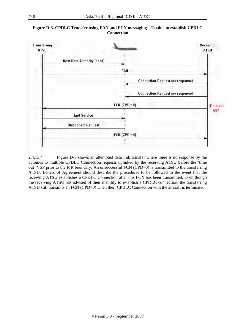
Asia/Pacific Regional ICD for AIDC
Version 3.0 - September 2007
D-8
Figure D-3. CPDLC Transfer using FAN and FCN messaging – Unable to establish CPDLC Connection
2.4.13.4 Figure D-3 shows an attempted data link transfer where there is no response by the avionics to multiple CPDLC Connection requests uplinked by the receiving ATSU before the ‘time out’ VSP prior to the FIR boundary. An unsuccessful FCN (CPD=0) is transmitted to the transferring ATSU. Letters of Agreement should describe the procedures to be followed in the event that the receiving ATSU establishes a CPDLC Connection after this FCN has been transmitted. Even though the receiving ATSU has advised of their inability to establish a CPDLC connection, the transferring ATSU still transmits an FCN (CPD=0) when their CPDLC Connection with the aircraft is terminated.

Asia/Pacific Regional ICD for AIDC
Version 3.0 – September 2007
D-9
Figure D-4. CPDLC Transfer using FAN and FCN messaging – initial NDA not delivered
2.4.13.5 Figure D-4 shows a data link transfer in which the original Next Data Authority message uplinked by the transferring ATSU is not delivered to the aircraft. An FCN (CPD=1) is transmitted by the receiving ATSU advising of the failure of their CPDLC Connection request. Another Next Data Authority message is uplinked to the aircraft. The transferring ATSU may send another FAN message after which the receiving ATSU successfully establishes a CPDLC Connection. Because this occurs before the time out VSP prior to the FIR boundary, a successful FCN (CPD=2) is transmitted back to the transferring ATSU. On termination of the CPDLC Connection, the transferring ATSU transmits an FCN (CPD=0) to the receiving ATSU. 3. PHASES OF FLIGHT 3.0.1 From an ATSU’s perspective, a flight is considered to progress through several phases. The IGM is principally concerned with three phases: Notification, Coordination, and Transfer of Control. 3.1 Notification Phase 3.1.1 An ATSU receives information during the Notification phase on a flight which will at some future time enter its ACI. 3.1.2 Notification Dialogue. ABI messages shall be used to transfer notification information. The sending ATSU transmits an ABI to the downstream ATSUs (D-ATSUs) (including the next Receiving ATSU - the R-ATSU) with which it must coordinate the flight. The sending ATSU is responsible for determining which D-ATSUs must be notified.

Asia/Pacific Regional ICD for AIDC
Version 3.0 - September 2007
D-10
3.1.3 Re-Route Notification. All D-ATSUs to the destination aerodrome shall be notified when a re-route has been made. Re-route dissemination shall be performed as a minimum capability on a stepwise (i.e., from one D-ATSU to the next D-ATSU) basis. In stepwise dissemination, an ATSU receiving an ABI is responsible for passing it on to any other affected D-ATSUs at the appropriate time. 3.1.4 Route to Destination. The above procedure requires the C-ATSU to acquire the complete route to destination. Initially, this information is found in the route field of the Filed Flight Plan (FPL). As re-routes occur, the filed route must be updated by the C-ATSU, and transmitted to D-ATSUs. In cases where this is not possible, the route field shall be terminated after the last known significant point with the ICAO truncation indicator, which is the letter “T”. Note: In accordance with PANS-ATM Doc 4444 the truncation indicator shall only follow a significant point or significant point/Cruising Speed and Cruising level in Field 15 and shall not follow an ATS route designator. 3.1.5 Re-route to new destination. The procedures described below apply when the notification and coordination of amended destinations has been included in bilateral agreements. 3.1.5.1 If an amendment to the destination aerodrome occurs prior to the transmission of the first ABI to an adjacent ATSU:
• Field 16 shall contain the original destination of the aircraft; • The Amended destination field shall contain the new destination of the aircraft.
3.1.5.2 Subsequent AIDC messages shall contain the new destination in Field 16, without reference to an amended destination. 3.1.5.3 If an amendment to the destination aerodrome occurs after the transmission of the first ABI to an adjacent ATSU, but before coordination has occurred, a new ABI shall be transmitted:
• Field 16 shall contain the original destination of the aircraft; • The Amended destination field shall contain the new destination of the aircraft.
3.1.5.4 Subsequent AIDC messages shall contain the new destination in Field 16, without reference to an amended destination. 3.1.5.5 The format of the Amended destination field shall be one of the options described below:
• ICAO four-letter location indicator; or • Name of the destination aerodrome, for aerodromes listed in Aeronautical
Information Publications; or • Latitude/longitude in the format dd[NS]ddd[EW] or ddmm[NS]dddmm[EW]; or • Bearing and distance from a significant point, using the following format:
the identification of the significant point, followed by the bearing from the significant point in the form of 3 figures giving degrees
magnetic, followed by the distance from the significant point in the form of 3 figures expressing
nautical miles.
3.16 Notification Cancellation. A notification can be cancelled using a MAC message. Receipt of a MAC by an ATSU means that any notification data previously received for that flight is no longer relevant. Filed flight plan information (and any modifications) shall continue to be held, in accordance with local ATSU procedures.
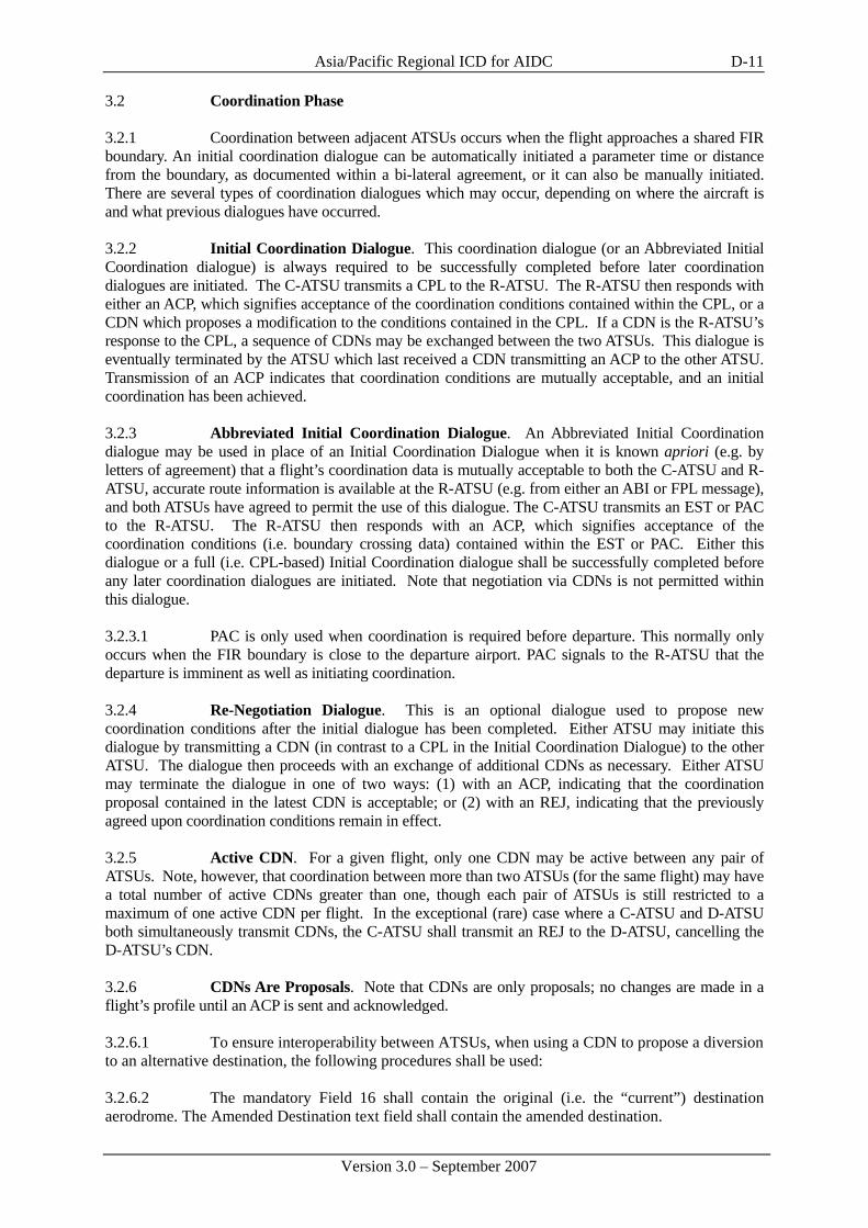
Asia/Pacific Regional ICD for AIDC
Version 3.0 – September 2007
D-11
3.2 Coordination Phase 3.2.1 Coordination between adjacent ATSUs occurs when the flight approaches a shared FIR boundary. An initial coordination dialogue can be automatically initiated a parameter time or distance from the boundary, as documented within a bi-lateral agreement, or it can also be manually initiated. There are several types of coordination dialogues which may occur, depending on where the aircraft is and what previous dialogues have occurred. 3.2.2 Initial Coordination Dialogue. This coordination dialogue (or an Abbreviated Initial Coordination dialogue) is always required to be successfully completed before later coordination dialogues are initiated. The C-ATSU transmits a CPL to the R-ATSU. The R-ATSU then responds with either an ACP, which signifies acceptance of the coordination conditions contained within the CPL, or a CDN which proposes a modification to the conditions contained in the CPL. If a CDN is the R-ATSU’s response to the CPL, a sequence of CDNs may be exchanged between the two ATSUs. This dialogue is eventually terminated by the ATSU which last received a CDN transmitting an ACP to the other ATSU. Transmission of an ACP indicates that coordination conditions are mutually acceptable, and an initial coordination has been achieved. 3.2.3 Abbreviated Initial Coordination Dialogue. An Abbreviated Initial Coordination dialogue may be used in place of an Initial Coordination Dialogue when it is known apriori (e.g. by letters of agreement) that a flight’s coordination data is mutually acceptable to both the C-ATSU and R-ATSU, accurate route information is available at the R-ATSU (e.g. from either an ABI or FPL message), and both ATSUs have agreed to permit the use of this dialogue. The C-ATSU transmits an EST or PAC to the R-ATSU. The R-ATSU then responds with an ACP, which signifies acceptance of the coordination conditions (i.e. boundary crossing data) contained within the EST or PAC. Either this dialogue or a full (i.e. CPL-based) Initial Coordination dialogue shall be successfully completed before any later coordination dialogues are initiated. Note that negotiation via CDNs is not permitted within this dialogue. 3.2.3.1 PAC is only used when coordination is required before departure. This normally only occurs when the FIR boundary is close to the departure airport. PAC signals to the R-ATSU that the departure is imminent as well as initiating coordination. 3.2.4 Re-Negotiation Dialogue. This is an optional dialogue used to propose new coordination conditions after the initial dialogue has been completed. Either ATSU may initiate this dialogue by transmitting a CDN (in contrast to a CPL in the Initial Coordination Dialogue) to the other ATSU. The dialogue then proceeds with an exchange of additional CDNs as necessary. Either ATSU may terminate the dialogue in one of two ways: (1) with an ACP, indicating that the coordination proposal contained in the latest CDN is acceptable; or (2) with an REJ, indicating that the previously agreed upon coordination conditions remain in effect. 3.2.5 Active CDN. For a given flight, only one CDN may be active between any pair of ATSUs. Note, however, that coordination between more than two ATSUs (for the same flight) may have a total number of active CDNs greater than one, though each pair of ATSUs is still restricted to a maximum of one active CDN per flight. In the exceptional (rare) case where a C-ATSU and D-ATSU both simultaneously transmit CDNs, the C-ATSU shall transmit an REJ to the D-ATSU, cancelling the D-ATSU’s CDN. 3.2.6 CDNs Are Proposals. Note that CDNs are only proposals; no changes are made in a flight’s profile until an ACP is sent and acknowledged. 3.2.6.1 To ensure interoperability between ATSUs, when using a CDN to propose a diversion to an alternative destination, the following procedures shall be used: 3.2.6.2 The mandatory Field 16 shall contain the original (i.e. the “current”) destination aerodrome. The Amended Destination text field shall contain the amended destination.

Asia/Pacific Regional ICD for AIDC
Version 3.0 - September 2007
D-12
3.2.6.3 The format of the Amended destination field shall be one of the options described below:
• ICAO four-letter location indicator; or • Name of the destination aerodrome, for aerodromes listed in Aeronautical
Information Publications; or • Latitude/longitude in the format dd[NS]ddd[EW] or ddmm[NS]dddmm[EW]; or • Bearing and distance from a significant point, using the following format:
the identification of the significant point, followed by the bearing from the significant point in the form of 3 figures giving
degrees magnetic, followed by the distance from the significant point in the form of 3 figures expressing
nautical miles.
3.2.6.4 The mandatory Field 16 contained in the operational response (ACP, REJ, CDN) to a CDN that proposes an amended destination shall contain the original (i.e. the “current”) destination aerodrome. Note: Due to the complexities involved with maintaining multiple profiles for “current destination” vs. “amended destination” ATSUs should consider prohibiting (via bilateral agreement) an operational response of CDN in any coordination renegotiation dialogues that contain an amended destination. 3.2.6.5 Provided that the proposed amendment is agreed to, all subsequent AIDC messages concerning this aircraft shall contain the new destination in the mandatory Field 16. 3.2.7 Cleared Flight Profile Update. The cleared flight profile (which is used for control purposes) shall only be updated after successful completion of a coordination dialogue, i.e., an ACP has been sent and acknowledged. This will require temporarily storing a proposed flight profile undergoing coordination separate from the cleared flight profile. The cleared flight profile shall then be updated using the newly coordinated profile upon successful completion of the coordination dialogue. 3.2.8 Automatic update of coordination conditions. When included in bilateral agreements between ATSUs, changes to previously agreed coordination conditions may be coordinated by way of a TRU message. The intent of this message is to allow amendments to certain elements of an aircraft’s clearance to be coordinated to an adjacent ATSU. In contrast to the CDN, there is no operational response to a TRU message – this message is used when there is agreement to what amendments can be made to an aircraft’s clearance by the controlling ATSU after initial coordination has occurred without prior coordination. 3.2.8.1 Whilst a number of the elements that may be coordinated by a TRU message may be more suited to an environment associated with an ATS Surveillance system (e.g. Heading, Direct to, etc), other elements may be applicable in any ATS environment (e.g. Cleared Flight Level, Off track deviation, Speed, etc). 3.2.8.2 The TRU message makes use of the Track data field to provide updated clearance information to an adjacent ATSU. Track data may be used to update assigned heading, assigned level, off track clearances, assigned speed or ‘direct to’ information. 3.2.8.3 When using the DCT/[position] element in the TRU message, [position] would normally be located on the flight planned route of the aircraft. Local procedures should specify the actions to be taken in the event that [position] is not on the flight planned route.

Asia/Pacific Regional ICD for AIDC
Version 3.0 – September 2007
D-13
3.2.8.4 For the purpose of the TRU message, the format of [position] is one of the following:
• From 2 to 5 characters, being the coded designator assigned to an en-route point or aerodrome; or
• ddmm[NS]dddmm[EW]; or • dd [NS]ddd[EW]; or • 2 or 3 characters being the coded identification of a navigation aid, followed by 3
decimal numerics giving the bearing from the point in degrees magnetic followed by 3 decimal numerics giving the distance from the point in nautical miles.
3.2.9 Coordination Cancellation. Coordination can be cancelled using a MAC message. Receipt of a MAC by an ATSU means that any coordination (or notification) data previously received for that flight is no longer relevant. Filed flight plan information (and any modifications) shall continue to be held, in accordance with local ATSU procedures. 3.2.10 Coordination and the ACI. ATSU A may need to coordinate with or provide information to ATSU B on all aircraft that enter ACI B, even if they do not enter FIR B. Consider the case of aircraft A in FIR A and aircraft B in FIR B, both flying near the FIR A - FIR B boundary but never penetrating the other FIR's airspace. The maintenance of adequate separation between these two aircraft may require coordination between or the provision of information to adjoining ATSUs. 3.3 Transfer of Control Phase 3.3.1 Transfer Dialogue. This phase occurs when the C-ATSU is ready to relinquish control of the flight to the R-ATSU, normally just before the FIR boundary crossing. The C-ATSU transfers a TOC message to the R-ATSU, which responds with an AOC message. The R-ATSU then becomes the C-ATSU once an application response for the AOC has been received. 3.3.2 Transfer of Control and the ACI. Note that the Transfer of Control process will not occur for all flights. Some flights fly near an FIR boundary, and may require coordination or the provision of other information, but do not actually enter the FIR. 4. FLIGHT STATE TRANSITIONS 4.1 Notifying States. Consider an aircraft that is currently within an ASIA/PAC FIR - FIR A - controlled by ATSU A (i.e. the C-ATSU) progressing towards the next FIR, FIR B (i.e. the R-ATSU). The aircraft is several hours from the boundary between the two FIRs. The flight is initially in a Pre-Notifying state from ATSU B’s perspective. ATSU B usually will have previously received a Filed Flight Plan (an FPL message), possibly with later amendments (as contained in CHG messages). ATSU A will employ a Notification dialogue to transfer information to ATSU B. (This transfer occurs at either a system parameter time (e.g. 60 minutes) or distance prior to the flight crossing the FIR A - FIR B boundary.) This places the flight in a Notifying state from ATSU B’s perspective. Additional Notification dialogues may be invoked by ATSU A as needed to inform ATSU B of flight changes. If the aircraft for some reason, for example a change in route, is no longer expected to penetrate ACI B, ATSU A sends a MAC message to ATSU B, causing the flight to be placed back in a Pre-Notifying state from ATSU B's perspective. 4.2 Initial Coordination States. An Initial Coordination Dialogue is employed to effect the initial coordination. ATSU A transmits a CPL to ATSU B when the aircraft is at a mutually agreed upon predetermined time (e.g. thirty minutes) or distance from the FIR A - FIR B boundary. The flight is now in a Negotiating state from both ATSU A’s and ATSU B’s perspectives. ATSU B can accept the conditions specified in the CPL "as is" by transmitting an ACP message to ATSU A, or it can propose modifications using the CDN message. Negotiations between the two ATSUs are carried out using the CDN until a mutually acceptable flight profile is achieved. This acceptance is signalled by one ATSU sending an ACP, as before, to the other ATSU. This establishes the initial coordination conditions. From the perspective of both ATSUs the flight is now in a Coordinated state.

Asia/Pacific Regional ICD for AIDC
Version 3.0 - September 2007
D-14
4.2.1 For an Abbreviated Initial Coordination, ATSU A transmits an EST to ATSU B when the aircraft is at a mutually agreed upon predetermined time (e.g. thirty minutes) or distance from FIR A - FIR B boundary. The flight is now in a Coordinating state. ATSU B responds with an ACP, which places the flight in a Coordinated state. This sequence of messages corresponds to an Abbreviated Initial Coordination Dialogue. 4.3 Re-Negotiation States. The initial coordination is typically the final coordination. However, in certain situations, it may be desirable, or necessary, to re-open the coordination dialogue after initial coordination has been completed. A Re-Negotiation dialogue is employed to effect profile changes. The dialogue is re-opened when one ATSU (either A or B) transmits a CDN to the other ATSU, causing the flight to be in a Re-Negotiating state. The dialogue proceeds as above using CDN messages until either an ACP or REJ is sent. Either ATSU can close the dialogue by issuing an ACP or REJ. An ACP closes the dialogue with a new, mutually agreed upon flight profile. An REJ, however, immediately terminates the dialogue with the previously accepted coordination conditions remaining in effect. Any proposed changes are null and void. Transmission of an ACP or REJ places the flight back into the Coordinated state. 4.4 Transfer States. Transfer of control is supported by the Transfer dialogue. ATSU A sends a TOC to ATSU B when the aircraft is about to cross the boundary. Alternatively, ATSU A can send a TOC when it is ready to relinquish control, even if the aircraft will remain in FIR A airspace several minutes before entering FIR B. The flight is now in a Transferring state from both ATSU A’s and ATSU B’s perspectives. ATSU B responds by transmitting an AOC to ATSU A, signalling acceptance of control responsibility. The flight is now in a Transferred state from ATSU A’s perspective. 4.5 Backward Re-Negotiating State. A flight’s profile may occasionally require changes after Transfer of Control has been completed, but the aircraft is still within ATSU A’s ACI. A Re-Negotiating dialogue is employed to effect profile changes after transfer has been completed. This places the flight in a Backward Re-Negotiating State, from both ATSUs’ perspectives. Completion of this dialogue returns the aircraft to the Transferred state. 4.6 Several flight states are identified in the above discussion. These states are listed in Table D-3 below.
Table D-3 Flight States
Flight State Description Pre-Notifying Flight plan information may have been received. Any previously received
notification and coordination information for the given flight cancelled by a MAC is no longer relevant.
Notifying The aircraft's progress is being monitored by one or more non-controlling ATSUs, in addition to the controlling ATSU.
Negotiating Coordination data is being exchange between the controlling ATSU and the receiving ATSU as part of the initial coordination dialogue.
Coordinating Abbreviated coordination data has been sent to the receiving ATSU. Coordinated Coordination of the boundary crossing conditions is completed. Re-Negotiating Coordination data is being exchange between the controlling ATSU and the receiving
ATSU as part of a later coordination dialogue. Transferring Air traffic control responsibility for the aircraft is in the process of being transferred
to the receiving ATSU. Transferred Air traffic control responsibility for the aircraft has been transferred to the receiving
ATSU. Backward- Re-Negotiating
The aircraft is now under the control of the receiving ATSU, but still near the boundary. Changes are being proposed to the coordination conditions while the aircraft is still in the vicinity of the boundary.

Asia/Pacific Regional ICD for AIDC
Version 3.0 – September 2007
D-15
TOC
Transferred
Backward- Re-negotiating
AOCTransferring Coordinated
Re-negotiating
CDN
CDN
MAC
Notifying
MAC
ACP
Negotiating
ABI CDN
REJ
ACP
CDN
Figure D -5 Flight State Transitions Diagram
CDN
ACP REJ
EST PAC
Coordinating
CPL
ACP
Pre-Notifying
ABI
TRU

Asia/Pacific Regional ICD for AIDC
Version 3.0 - September 2007
D-16
4.7 A flight state transition diagram is shown in Figure D-5. This diagram depicts graphically how the flight transitions from one state to the next. It can be seen that the ASIA/PAC AIDC messages act as triggers, forcing the necessary state transitions. A description of the allowable flight state transitions, along with the message event that triggers the transition, is given in Table D-4 below.
Table D-4 Flight State Transitions
State Transition
Message Trigger
Description
Pre-Notifying/ Notifying
ABI An initial ABI begins the Notification phase.
Notifying/ Notifying
ABI An ABI updates the information a downstream ATSU maintains on a flight that is expected to enter its ACI at some future time. This data canbe sent hours in advance of the actual entry.
Notifying/ Pre-Notifying
MAC A flight that was expected to enter a downstream ATSU's ACI will no longer do so.
Notifying/ Negotiating
CPL A CPL is used to initiate the Coordination process for an aircraft that will enter the downstream ATSU’s ACI. A CPL contains the current clearance to destination.
Notifying/ Coordinating
EST An EST is used to initiate an Abbreviated Coordination process for an aircraft that will enter the downstream ATSU’s ACI.
Notifying/ Coordinating
PAC A PAC is used to initiate an Abbreviated Coordination process for an aircraft, not yet airborne, that will enter the downstream ATSU’s ACI.
Negotiating/ Negotiating
CDN If the downstream ATSU does not like the current clearance (and boundary crossing conditions), a Negotiation process is carried out using CDNs.
Negotiating/ Coordinated
ACP
The negotiation process is terminated when one ATSU signals its acceptance of the coordination conditions using an ACP.
Coordinating/ Coordinated
ACP The Abbreviated Coordination dialogue is terminated by the receiving ATSU transmitting an ACP.
Coordinated/ Re-Negotiating
CDN The coordination dialogue can be re-opened at any time after the initial coordination and before the initiation of the transfer of control procedure.
Re-Negotiating/ Re-Negotiating
CDN Either ATSU may attempt to change the previously agreed upon coordination conditions any time after the initial coordination dialogue has been completed.
Re-Negotiating/ Coordinated
ACP REJ
An ACP terminates a re-negotiation dialogue, with a new mutually agreed upon profile in effect. An REJ immediately terminates the dialogue, with the coordination conditions remaining as previously agreed (which is usually, but not necessarily, the initial coordination conditions).
Coordinated/ Coordinated
TRU A TRU may be sent by the controlling ATSU after the initial coordination dialogue has been completed to update previously agreed coordination conditions
Coordinated/ Transferring
TOC A TOC is sent after Coordination occurs but (usually just) before the boundary is crossed to the accepting ATSU. The TOC informs the accepting ATSU that it now has control authority for the aircraft.
Coordinated/ Pre-Notifying
MAC A flight that was expected to enter a downstream ATSU's ACI will no longer do so.
Transferring/ Transferred
AOC The formerly downstream ATSU is now the controlling ATSU.

Asia/Pacific Regional ICD for AIDC
Version 3.0 – September 2007
D-17
State Transition
Message Trigger
Description
Transferred/ Backward- Re-Negotiating
CDN An attempt is made (by either the previous or new controlling ATSU) to change the coordination conditions while the aircraft is near the common boundary.
Backward- Re-Negotiating/ Backward- Re-Negotiating
CDN Either ATSU may attempt to change the previously agreed upon coordination conditions any time after transfer of control has been completed, but while the aircraft remains in the common boundary region.
Backward- Re-Negotiating/ Transferred
ACP REJ
Similar to a Re-Negotiation/Coordinated state transition. An ACP terminates a backward coordination dialogue, with a new mutually agreed upon profile in effect. An REJ immediately terminates the dialogue, with the coordination conditions remaining as previously agreed (which is usually, but not necessarily, the initial coordination conditions).
5. MESSAGE SEQUENCING 5.1 The preceding section identified the flight states and showed how the aircraft transitions from one state to the next, based on the receipt of ASIA/PAC AIDC messages by ATSU B. In this section, a table of two-message sequences is constructed, as shown in Table D-5. These sequences identify the allowable messages (the next message column) that may correctly follow a given, just received message (the first column). Application Management messages LAM and LRM are not shown.
Table D-5 Message Sequences
Received Message
Next Valid Message
Comments
Notification Sequences ABI ABI Update the flight information.
MAC Indicates that the flight is no longer expected to enter the downstream ATSU’s ACI.
CPL Receipt of the ABI signals the beginning of the Notification phase for a particular flight. Coordination will take place when the aircraft is within a parameter distance/time of the boundary.
EST Receipt of the ABI signals the beginning of the Notification phase for a particular flight. Coordination will take place when the aircraft is within a parameter distance/time of the boundary.
Coordination Sequences ACP The aircraft's current clearance is acceptable. CPL CDN The aircraft's current clearance is not acceptable to the receiving airspace and
must be modified. EST ACP The boundary crossing conditions are in accordance with the agreement that
exists between the two ATSUs. PAC ACP The boundary crossing conditions are in accordance with the agreement that
exists between the two ATSUs. ACP The negotiated clearance is acceptable to both ATSUs. CDN The proposed clearance modification is not acceptable to one of the airspaces
and a new proposal is submitted.
CDN
REJ The last clearance agreed to by both airspaces must be honoured.

Asia/Pacific Regional ICD for AIDC
Version 3.0 - September 2007
D-18
CDN The proposed clearance modification is not acceptable to one of the airspaces and a new proposal is submitted.
TOC The aircraft is at or near the boundary. TRU Notification of an amendment to the previously accepted clearance
TRU
MAC Indicates that the flight is no longer expected to enter the downstream ATSU’s ACI
CDN A request for modification of a previously accepted clearance is submitted. TRU Notification of an amendment to the previously accepted clearance TOC The aircraft is at or near the boundary.
ACP
MAC Indicates that the flight is no longer expected to enter the downstream ATSU's ACI.
Transfer of Control Sequences TOC AOC The aircraft is at or near the boundary. AOC CDN A request for modification of a previously accepted clearance is submitted.
5.2 Table D-6 lists the AIDC messages which are valid for each state. The ATSU which can transmit the message is also identified.
Table D-6 Valid Messages by ATSU
Flight State Message Sent by Notifying ABI Controlling ATSU Notifying MAC Controlling ATSU Notifying CPL Controlling ATSU Notifying EST Controlling ATSU Notifying PAC Controlling ATSU Negotiating CDN Either ATSU Negotiating ACP Either ATSU Coordinating ACP Receiving ATSU Coordinated CDN Either ATSU Coordinated TRU Controlling ATSU Coordinated TOC Controlling ATSU Coordinated MAC Controlling ATSU Re-Negotiating CDN Either ATSU Re-Negotiating ACP Either ATSU Re-Negotiating REJ Either ATSU Transferring AOC Receiving ATSU Transferred CDN Either ATSU Backward- Re-Negotiating CDN Either ATSU
Backward- Re-Negotiating ACP Either ATSU
Backward- Re-Negotiating REJ Either ATSU

Asia/Pacific Regional ICD for AIDC
Version 3.0 – September 2007
D-19
6. OTHER MESSAGES 6.0 The previous sections have discussed the use of Notification, Coordination, Transfer of Control, and Application Management messages. There are two remaining message subgroups in the ASIA/PAC AIDC Messages: (1) General Information messages; and (2) Surveillance Data Transfer messages. All messages within these two subgroups require an application response; no operational response is defined. 6.1 General Information Messages. 6.1.1 EMG and MIS Messages. These messages support the exchange of text information between ATSUs. A communicator (usually a person, but a computer or application process is also permitted) in one ATSU can send a free text message to a functional address at another ATSU. Typical functional addresses could be an area supervisor or an ATC sector. If further EMG or MIS messages are transmitted in response to a previously received EMG or MIS, the later messages shall include the original message identifier within field 3 of the AFTN header. The EMG shall have an AFTN emergency priority (SS). 6.1.2 Track Definition Message. The TDM is generated and disseminated to all affected ATSUs. It is also sent to Airline Operational Control (AOC) Centres, where it is used for flight planning purposes. This message contains, in a structured text format, the track definition and the time when it is active. 6.2 Surveillance Data Transfer Messages. The ADS message is used to transfer data contained within an ADS-C report, including optional ADS-C groups, to an adjacent ATSU. 6.2.1 The ADS message contains a text field – the ADS-C data field - which contains information from the ADS-C report in its original hexadecimal format. The ADS-C data field consists of the text that immediately follows the “ADS” IMI (but excluding the 4 character CRC) within the Application data portion of the ADS-C report. 6.2.2 The following example shows an encoded ACARS ADS-C report – as it would be received by an ATSU – as well as an example of what information from this report would be transferred into the corresponding ADS-C data field. The ATSU receiving the AIDC ADS message simply decodes the ADS-C data field, and extracts the data that is required by the ATSU. ACARS ADS-C report
QU BNECAYA .QXSXMXS 011505 PAR FI NZ0090/AN ZK-OKC DT QXT POR1 011505 F59A - ADS.ZK-OKC030007FF946B6F6DC8FC044B9D0DFC013B80DA88FC0A64F9E4438B4AC8FC000E34D0EDC00010140F3E8660F3
ADS-C data field
ADS/.ZK-OKC030007FF946B6F6DC8FC044B9D0DFC013B80DA88FC0A64F9E4438B4AC8FC000E34D0EDC00010140F3E86
Note. Because it is part of the 7 character registration field, the leading “.” must be retained in front of the registration (“.ZK-OKC”). The 4 character CRC (“60F3”) at the end of the ACARS message is not included in the ADS-C data field. 6.2.3 The types of ADS-C reports (i.e. periodic or event) transmitted by the AIDC ADS message shall be in accordance with bilateral agreements. When implementing the AIDC ADS message, ATSUs should consider the effect of relaying numerous ADS-C periodic reports via ground-ground links (e.g. AFTN) when a high periodic reporting rate is in effect.

Asia/Pacific Regional ICD for AIDC
Version 3.0 - September 2007
D-20
Note 1. The AIDC ADS message is used to transfer ADS-C information only. Other messaging protocols exist for the transfer of ADS-B information. Note 2. While the AIDC ADS message may be used to transfer ADS-C information this data may also be transferred using the ACARS Ground-Ground network by re-addressing the received ADS-C message to the other ATSU. States should agree on the method to be used on a bilateral basis. Example: Brisbane ATSU (BNECAYA) receives an ADS-C downlink via the ACARS network from its Datalink Service Provider SITA (QXSXMXS) QU BNECAYA .QXSXMXS 011505 PAR FI NZ0090/AN ZK-OKC DT QXT POR1 011505 F59A -ADS.ZK-OKC0300FF946B6F6DC8FC044B9D0DFC013B80DA88FC0A64F9E4438B4AC8FC00 0E34D0EDC00010140F3E8660F3 Brisbane re-addresses the downlink and forwards to Auckland via the ACARS Ground-Ground network: QU AKLCBYA .BNECAYA 011505 PAR FI NZ0090/AN ZK-OKC DT QXT POR1 011505 F59A -ADS.ZK-OKC0300FF946B6F6DC8FC044B9D0DFC013B80DA88FC0A64F9E4438B4AC8FC00 0E34D0EDC00010140F3E8660F3 7. EXAMPLES 7.1 Standard Coordination 7.1.1 Brisbane transmits a notification message (ABI) to Auckland forty five minutes prior to the time that QFA108 is expected to cross the FIR boundary (1209). The destination of the flight is Christchurch. 7.1.2 The abbreviated coordination message (EST) is transmitted by Brisbane thirty minutes prior to the boundary estimate (which is now 1213). Auckland accepts the proposed coordination conditions by responding with an ACP. 7.1.3 Brisbane transfers ATC responsibility approaching the FIR boundary by transmitting a TOC. Auckland accepts ATC responsibility by responding with an AOC. Note. The timing of the transmission of these messages is defined in bilateral agreements between the two units.

Asia/Pacific Regional ICD for AIDC
Version 3.0 – September 2007
D-21
Example 1. Standard coordination
Brisbane Auckland (ABI-QFA108-YBBN-33S163E/1209F350 -NZCH-8/IS-9/B744/H-10/SDHIWRJ -15/M084F350 35S164E 36S165E ...)
(EST-QFA108-YBBN-33S163E/1213F350-NZCH)
(ACP-QFA108-YBBN-NZCH) (TOC-QFA108-YBBN-NZCH) (AOC-QFA108-YBBN-NZCH) 7.2 Negotiation of coordination conditions 7.2.1 Brisbane transmits a notification message (ABI) to Auckland forty five minutes prior to the time that QFA56 is expected to cross the FIR boundary (1209). The destination of the flight is Christchurch. 7.2.2 The coordination message (CPL) is transmitted by Brisbane thirty minutes prior to the boundary estimate (which is now 1213). 7.2.3 Auckland responds with a negotiation message (CDN) requesting a change in the boundary crossing altitude to F390. Brisbane responds with an ACP, indicating that the revised altitude is acceptable. 7.2.4 Brisbane transfers ATC responsibility approaching the FIR boundary by transmitting a TOC. Auckland accepts ATC responsibility by responding with an AOC. Note. The timing of the transmission of these messages is defined in bilateral agreements between the two units. Example 2. Negotiation of Coordination Conditions
Brisbane Auckland (ABI-QFA56-YBBN-33S163E/1209F350-NZCH-8/IS-9/B744/H-10/SDHIWRJ-15/M084F350 35S164E 36S165E ...)
(CPL-QFA56-IS-B744/H-SDHIWRJ-YBBN -33S163E/1213F350-M084F350 35S164E 36S165E NZCH -0.)
(CDN-QFA56-YBBN-NZCH -14/33S163E/1213F390)
(ACP-QFA56-YBBN-NZCH) (TOC-QFA56-YBBN-NZCH) (AOC-QFA56-YBBN-NZCH) 7.3 Re-negotiation rejected 7.3.1 Brisbane transmits a notification message (ABI) to Auckland forty five minutes prior to the time that QFA108 is expected to cross the FIR boundary (1209). The destination of the flight is Christchurch.

Asia/Pacific Regional ICD for AIDC
Version 3.0 - September 2007
D-22
7.3.2 The coordination message (CPL) is transmitted by Brisbane thirty minutes prior to the boundary estimate (which is now 1213). Auckland accepts the proposed coordination conditions without modification by responding with an ACP. 7.3.3 Some time after the initial coordination process has been completed, but before the start of the Transfer of Control process, Auckland requests an amendment to the boundary crossing altitude by transmitting a negotiation message (CDN). Brisbane cannot accept the proposed change due to conflicting traffic in its FIR, and therefore rejects the request (REJ). 7.3.4 Brisbane transfers ATC responsibility approaching the FIR boundary by transmitting a TOC. Auckland accepts ATC responsibility by responding with an AOC. Note. The timing of the transmission of these messages is defined in bilateral agreements between the two units. Example 3. Rejection of Renegotiated Coordination
Brisbane Auckland (ABI-QFA108-YBBN-33S163E/1209F350 -NZCH-8/IS-9/B744/H-10/SDHIWRJ -15/M084F350 35S164E 36S165E ...)
(CPL-QFA108-IS-B744/H-SDHIWRJ-YBBN -33S163E/1213F350-M084F350 35S164E 36S165E NZCH-0 ...)
(ACP-QFA108-YBBN-NZCH)
(CDN-QFA108-YBBN-NZCH -14/33S163E/1213F390)
(REJ-QFA108-YBBN-NZCH) (TOC-QFA108-YBBN-NZCH) (AOC-QFA108-YBBN-NZCH) 7.4 Abbreviated coordination 7.4.1 Several minutes before AAA842’s departure time (e.g. at taxi time), coordination between Bali and Brisbane is effected by Bali transmitting a coordination message (PAC). This message alerts Brisbane that the flight is pending, and indicates a boundary estimate of 1213 at F290. Brisbane accepts the coordination conditions by responding with an ACP. 7.4.2 On departure, the aircraft’s actual estimate differs from that coordinated by more than the value specified in bilateral agreements. The new estimate is coordinated to Brisbane by Bali transmitting a CDN message to Brisbane. Brisbane accepts this revised estimate by responding with an ACP message. 7.4.3 Bali transfers ATC responsibility approaching the FIR boundary by transmitting a TOC. Brisbane accepts ATC responsibility by responding with an AOC. Note. The timing of the transmission of these messages is defined in bilateral agreements between the two units.

Asia/Pacific Regional ICD for AIDC
Version 3.0 – September 2007
D-23
Example 4. Abbreviated coordination
Bali Brisbane
(PAC-AAA842/A4534-IS-B737/M-WRRR- -OGAMI/1213F290-YPPH ...)
(ACP-AAA842/A4534-WRRR-YPPH) (CDN-AAA842/A4534-WRRR-YPPH-14/OGAMI/1219F290)
(ACP-AAA842/A4534-WRRR-YPPH) (TOC-AAA842/A4534-WRRR-YPPH) (AOC-AAA842/A4534-WRRR-YPPH) 7.5 Multiple notifications + AIDC cancellation 7.5.1 Brisbane transmits a notification message (ABI) to Auckland forty five minutes prior to the time that QFA11 is expected to cross the FIR boundary (1105). The destination of the flight is Los Angeles. 7.5.2 Prior to transmitting the coordination message, a modification to the cleared flight level is made resulting in the transmission of another notification message. This ABI contains the latest boundary information on the aircraft, showing that the current boundary estimate is now 1107. 7.5.3 The abbreviated coordination message (EST) is transmitted by Brisbane thirty minutes prior to the boundary estimate (which is now 1108). Auckland accepts the proposed coordination conditions by responding with an ACP 7.5.4 Due to weather QFA11 requests, and is issued, an amended route clearance that will now no longer affect Auckland. To advise of the cancellation of any previously transmitted AIDC messages, a MAC message is transmitted to Auckland. Note. The timing of the transmission of these messages is defined in bilateral agreements between the two units. Example 5. Multiple notifications + AIDC cancellation
Brisbane Auckland (ABI-QFA11-YSSY-31S163E/1105F290 -KLAX-8/IS-9/B744/H-10/SDHIWRJ -15/M085F290 33S158E 30S168E ...)
(ABI-QFA11-YSSY-31S163E/1107F310 -KLAX-8/IS-9/B744/H-10/SDHIWRJ -15/M084F290 33S158E 30S168E ...)
(EST-QFA11-YSSY-31S163E/1108F310-KLAX)
(ACP-QFA11-YSSY-KLAX) (MAC-QFA11-YSSY-KLAX)

Asia/Pacific Regional ICD for AIDC
Version 3.0 - September 2007
D-24
7.6 Multiple negotiations 7.6.1 Brisbane transmits a notification message (ABI) to Auckland forty five minutes prior to the time that QFA108 is expected to cross the FIR boundary (1209). The destination of the flight is Christchurch. 7.6.2 The abbreviated coordination message (EST) is transmitted by Brisbane thirty minutes prior to the boundary estimate (which is now 1213). Auckland accepts the proposed coordination conditions by responding with an ACP 7.6.3 QFA108 requests F370. The bilateral Letter of Agreement between Brisbane and Auckland requires that prior coordination is required before issuing a change of level after initial coordination. Brisbane transmits a negotiation message (CDN) proposing a change of level to F370. This level is not available in Auckland’s airspace but an alternative level is available. Auckland therefore responds with a negotiation message proposing F360. Brisbane responds with an ACP, indicating that this level is acceptable to Brisbane (and to QFA108). 7.6.4 Brisbane transfers ATC responsibility approaching the FIR boundary by transmitting a TOC. Auckland accepts ATC responsibility by responding with an AOC. Note1. The timing of the transmission of these messages is defined in bilateral agreements between the two units. Note2. Complex re-negotiations may be more easily solved by voice communication Example 6. Multiple negotiations
Brisbane Auckland (ABI-QFA108-YBBN-33S163E/1209F350 -NZCH-8/IS-9/B744/H-10/SDHIWRJ -15/M084F350 35S164E 36S165E ...)
(EST-QFA108-YBBN-33S163E/1213F350-NZCH) (ACP-QFA108-YBBN-NZCH) (CDN-QFA108-YBBN-NZCH -14/33S163E/1213F370)
(CDN-QFA108-YBBN-NZCH -14/33S163E/1213F360)
(ACP-QFA108-YBBN-NZCH) (TOC-QFA108-YBBN-NZCH) (AOC-QFA108-YBBN-NZCH) 7.7 Standard coordination with proposed amended destination 7.7.1 Brisbane transmits a notification message (ABI) to Auckland forty five minutes prior to the time that ANZ136 is expected to cross the FIR boundary (1400). The destination of the flight is Christchurch. 7.7.2 The abbreviated coordination message (EST) is transmitted by Brisbane thirty minutes prior to the boundary estimate (which is now 1401). Auckland accepts the proposed coordination conditions by responding with an ACP.

Asia/Pacific Regional ICD for AIDC
Version 3.0 – September 2007
D-25
7.7.3 ANZ136 requests a deviation to Auckland (NZAA). Brisbane transmits a Coordination message (CDN) to Auckland proposing changes to the previously agreed coordination conditions (route and boundary estimate) as well as the new destination. Auckland accepts the proposed revision(s) by the transmission of an ACP. All subsequent AIDC messages for ANZ136 contain “NZAA” as the destination aerodrome. 7.7.4 Brisbane transfers ATC responsibility approaching the FIR boundary by transmitting a TOC. Auckland accepts ATC responsibility by responding with an AOC. Note. The timing of the transmission of these messages is defined in bilateral agreements between the two units. Example 7. Coordination of amended destination
Brisbane Auckland (ABI-ANZ136-YBBN-RUNOD/1400F350 -NZCH-8/IS-9/A320/M-10/SDHIWR -15/M078F350 SCOTT Y32 LOKET L503 LALAP DCT ...)
(EST-ANZ136-YBBN-33S163E/1401F350-NZCH)
(ACP-ANZ136-YBBN-NZCH) (CDN-ANZ136-YBBN-NZCH-14/ESKEL/1357F350-15/ SCOTT Y32 LOKET WOOLY ESKEL L521 AA-DEST/NZAA)
(ACP-ANZ136-YBBN-NZCH) (TOC-ANZ136-YBBN-NZAA) (AOC-ANZ136-YBBN-NZAA)
7.8 Standard coordination including FAN/FCN exchange 7.8.1 Brisbane transmits a notification message (ABI) to Auckland forty five minutes prior to the time that UAL815 is expected to cross the FIR boundary (0330). 7.8.2 The abbreviated coordination message (EST) is transmitted by Brisbane thirty minutes prior to the boundary estimate. Auckland accepts the proposed coordination conditions by responding with an ACP. 7.8.3 Brisbane transmits a FAN message to Auckland providing the logon information that Auckland requires to establish a CPDLC connection as well as ADS contracts. 7.8.4 When a CPDLC connection is established, Auckland transmits an FCN to Brisbane, containing the appropriate frequency for the aircraft to monitor. 7.8.5 Brisbane transfers ATC responsibility approaching the FIR boundary by transmitting a TOC. Auckland accepts ATC responsibility by responding with an AOC. 7.8.6 Brisbane terminates the CPDLC connection with UAL815, and transmits an FCN to Auckland to advise them that the CPDLC connection has been terminated. Note. The timing of the transmission of these messages is defined in bilateral agreements between the two units.

Asia/Pacific Regional ICD for AIDC
Version 3.0 - September 2007
D-26
Example 8. Standard coordination including FAN and FCN exchanges
Brisbane Auckland (ABI-UAL815/-YSSY-3200S16300E/0330F290 -KLAX-8/IS-9/B744/H-10/SDHIRZYWJP/CD-15/N0499F310 NOBAR A579 JORDY DCT 3200S16000E 3050S16300E 2800S16500E..)
(EST-UAL815-YSSY-33S163E/0330F290-KLAX)
(ACP-UAL815-YSSY-KLAX) (FAN-UAL815-YSSY-KLAX-SMI/FML FMH/UAL815 REG/N123UA FPO/3330S15910E FCO/ATC01 FCO/ADS01)
(FCN-UAL815-YSSY-KLAX-CPD/2-FREQ/13261)
(TOC-UAL815-YSSY-KLAX) (AOC-UAL815-YSSY-KLAX) (FCN-UAL815-YSSY-KLAX-CPD/0)
7.9 Standard coordination with TRU update 7.9.1 An abbreviated coordination message (EST) is transmitted by Melbourne as soon as UAE412 departs Sydney. Brisbane accepts the proposed coordination conditions by responding with an ACP. 7.9.2 The Sydney Departures controller assigns the aircraft a heading of 100 degrees magnetic and issues an instruction to maintain F200. A TRU is transmitted to update the Brisbane controllers’ flight details. 7.9.3 Melbourne transfers ATC responsibility approaching the FIR boundary by transmitting a TOC. Brisbane accepts ATC responsibility by responding with an AOC. Example 9. Coordination of amended clearances via TRU
Brisbane Auckland (EST-UAE412-YSSY-EVONN/0130F280-NZAA)
(ACP-UAE412-YSSY-NZAA) (TRU-UAE412-YSSY-NZAA-HDG/100 CFL/F200)
(TOC-UAE412-YSSY-NZAA) (AOC-UAE412-YSSY-NZAA)
8. NOTES 8.1 The IGM concerns communications between two ATSU’S within the ASIA/PAC Regions. Inter-center communications within one country, and communications with ATSUs outside the ASIA/PAC regions, though important to an ATC system’s design and implementation, are not part of the scope of this material.

Asia/Pacific Regional ICD for AIDC
Version 3.0 – September 2007
E-1
APPENDIX E - RELATIONSHIP TO ICAO AIDC MESSAGES 1. The AIDC message set can be tailored to satisfy regional requirements. The OPLINKP documentation defining the AIDC data link application provides three means for achieving regional adaptation of the AIDC messages: a) Regions select an AIDC subset that will support their regional operational
procedures; b) The selected messages are tailored by mandating the usage of optional
components into one of three classes:
(1) the optional component that must always be used; (2) the optional component that must never be used; (3) the optional component is truly optional;
c) For interim, pre-ATN implementations, encoding rules may be specified by a
region. The most frequently used encoding rules today employ ICAO ATS fields and messages. The default encoding rules are the ISO Packed Encoding rules.
2. Using the regional tailoring procedures stated above, the ASIA/PAC Core messages are related to a subset of the AIDC messages and are shown in Table E-1. 3. The encoding rules employed within the ASIA/PAC will remain for the foreseeable future as the ICAO ATS field and message-based, character-oriented rules currently defined in the ASIA/PAC AIDC Interface Control Document (ICD) (and ICAO PANS-ATM Doc 4444).

Asia/Pacific Regional ICD for AIDC
Version 3.0 – September 2007
E-2
Table E –1 ASIA/PAC AIDC/ICAO AIDC Relationship
ICAO AIDC message ASIA/PAC AIDC message ICAO AIDC message ASIA/PAC AIDC
message ICAO AIDC message
ASIA/PAC AIDC message
Mandatory fields Optional fields
Notify ABI Aircraft identification Departure aerodrome Destination aerodrome Boundary estimate data
Aircraft identification SSR Mode and Code (where applicable) Departure aerodrome Destination aerodrome Boundary estimate data Number of aircraft Aircraft type Wake turbulence category Route
Flight rules Type of flight Number of aircraft (if more than one in the flight) Aircraft type Wake turbulence category CNS equipment Route Amended destination Code (SSR) Other information
Flight rules Equipment Other information Amended destination
Coordinate Initial
CPL Aircraft identification Departure aerodrome Destination aerodrome Boundary estimate data
Aircraft identification SSR Mode and Code (where applicable) Departure aerodrome Destination aerodrome Boundary estimate data Flight rules Number of aircraft Aircraft type Wake turbulence category Equipment Route Other information
Flight rules Type of flight Number of aircraft (if more than one in the flight) Aircraft type Wake turbulence category CNS equipment Route Amended destination Code (SSR) Other information

Asia/Pacific Regional ICD for AIDC E-3
Version 3.0 – September 2007
ICAO AIDC message ASIA/PAC AIDC message ICAO AIDC message ASIA/PAC AIDC
message ICAO AIDC message
ASIA/PAC AIDC message
Mandatory fields Optional fields
Coordinate Initial
EST Aircraft identification Departure aerodrome Destination aerodrome Boundary estimate data
Aircraft identification SSR Mode and Code (where applicable) Departure aerodrome Destination aerodrome Boundary estimate data
Flight rules Type of flight Number of aircraft (if more than one in the flight) Aircraft type Wake turbulence category CNS equipment Route Amended destination Code (SSR) Other information
Coordinate Initial
PAC Aircraft identification Departure aerodrome Destination aerodrome Boundary estimate data
Aircraft identification SSR Mode and Code (where applicable) Departure aerodrome Destination aerodrome Boundary estimate data
Flight rules Type of flight Number of aircraft (if more than one in the flight) Aircraft type Wake turbulence category CNS equipment Route Amended destination Code (SSR) Other information
Flight rules Number of aircraft Aircraft type Wake turbulence category Equipment Route Other information.
Coordinate Negotiate
CDN Aircraft identification Departure aerodrome Destination aerodrome Boundary estimate data
Aircraft identification SSR Mode and Code (where applicable) Departure aerodrome Destination aerodrome
Flight rules Type of flight Number of aircraft (if more than one in the flight) Aircraft type Wake turbulence category CNS equipment Route Amended destination Code (SSR) Other information
Equipment Boundary estimate data Route Other information Amended destination

Asia/Pacific Regional ICD for AIDC
Version 3.0 – September 2007
E-4
ICAO AIDC message ASIA/PAC AIDC message ICAO AIDC message ASIA/PAC AIDC
message ICAO AIDC message
ASIA/PAC AIDC message
Mandatory fields Optional fields
Coordinate Accept
ACP Aircraft identification SSR Mode and Code (where applicable) Departure aerodrome Destination aerodrome
Aircraft identification Departure aerodrome Destination aerodrome
Coordinate Reject
REJ Aircraft identification SSR Mode and Code (where applicable) Departure aerodrome Destination aerodrome
Aircraft identification Departure aerodrome Destination aerodrome
Coordinate Standby
N/A Aircraft identification Departure aerodrome Destination aerodrome
Coordinate Cancel
MAC Aircraft identification Departure aerodrome Destination aerodrome
Aircraft identification SSR Mode and Code (where applicable) Departure aerodrome Destination aerodrome
Fix Reason for cancellation
Boundary Estimate Data Other Information
Coordinate Update
TRU Aircraft identification Departure aerodrome Destination aerodrome Boundary estimate data
Aircraft identification SSR Mode and Code (where applicable) Departure aerodrome Destination aerodrome Track data
Flight rules Type of flight Number of aircraft (if more than one in the flight) Aircraft type Wake turbulence category CNS equipment Route Amended destination Code (SSR) Other information
Transfer Initiate
N/A Aircraft identification Executive data (if available)
Track data
Transfer Conditions Proposal
N/A Aircraft identification Executive data (if available)
Track data

Asia/Pacific Regional ICD for AIDC E-5
Version 3.0 – September 2007
ICAO AIDC message ASIA/PAC AIDC message ICAO AIDC message ASIA/PAC AIDC
message ICAO AIDC message
ASIA/PAC AIDC message
Mandatory fields Optional fields
Transfer Conditions Accept
N/A Aircraft identification
Frequency
Transfer Communication Request
N/A Aircraft identification
Frequency
Transfer Communication
N/A Aircraft identification Executive data and/or Release indication (if available)
Frequency Track data
Transfer Communication Assume
N/A Aircraft identification
Transfer Control
TOC Aircraft identification
Aircraft identification SSR Mode and Code (where applicable) Departure aerodrome Destination aerodrome
Departure aerodrome Destination aerodrome Executive data
Transfer Control Assume
AOC Aircraft identification
Aircraft identification, SSR Mode and Code (where applicable) Departure aerodrome Destination aerodrome
Departure aerodrome Destination aerodrome
General Point
N/A Aircraft identification Departure aerodrome Destination aerodrome
Sector designator (sending) Sector designator (receiving) Flight rules Type of flight Number of aircraft (if more than one in the flight) Aircraft type Wake turbulence category CNS equipment Route Track data Code (SSR) Other information

Asia/Pacific Regional ICD for AIDC
Version 3.0 – September 2007
E-6
ICAO AIDC message ASIA/PAC AIDC message ICAO AIDC message ASIA/PAC AIDC
message ICAO AIDC message
ASIA/PAC AIDC message
Mandatory fields Optional fields
General Executive Data
N/A Aircraft identification
Executive data Frequency
Free Text Emergency
EMG Facility designation or Aircraft identification Free text
Functional address or Aircraft identification SSR Mode and Code (where applicable) Other information
Free Text General
MIS Facility designation or Aircraft identification Free text
Functional address or Aircraft identification SSR Mode and Code (where applicable) Other information
Application Accept LAM Application Reject LRM Error code Other Information Error data N/A ASM N/A FAN Aircraft identification
SSR Mode and Code (where applicable) Departure aerodrome Destination aerodrome Application data
N/A FCN Aircraft identification SSR Mode and Code (where applicable) Departure aerodrome Destination aerodrome Communication Status
N/A ADS Aircraft identification SSR Mode and Code (where applicable) Departure aerodrome Destination aerodrome ADS-C data

Asia/Pacific Regional ICD for AIDC
Version 3.0 – September 2007
F-1
APPENDIX F - INTERIM OPERATIONAL SUPPORT 1. INTRODUCTION 1.1 This ICD describes the end-state messages to be used within the ASIA/PAC region to ensure interoperability between automated ATS systems. However, during the transition to this end state architecture, current operations must be documented and supported. This appendix is the repository of messages not found in other ICD sections which will be used to support current operations during the interim transition period. 1.2 Each interim message will be described in a separate paragraph. Those ATS Providers employing an interim message contained in this appendix shall document this usage in the appropriate bilateral agreements. 2. INTERIM MESSAGES 2.1 Estimate (EST) Message 2.1.1 The Estimate message is contained within the Core Message set. However, its use has been constrained to those situations in which a flight will cross an FIR boundary in accordance with existing letters of agreement. 2.1.2 An EST message may be used in any situation in which a CPL is permitted. The EST is in actuality an abbreviated CPL, contingent upon prior receipt of route and ancillary information. This information could be provided by an FPL or ABI message. 2.1.3 Those ATS Provider States employing an EST in the more general manner during the interim transition period shall document this usage in the appropriate bi-lateral agreements. 2.1.4 The EST message format shall be as described in the Core Message set.

Asia/Pacific Regional ICD for AIDC G-1
Version 3.0 – September 2007
APPENDIX G – TEMPLATES FOR BILATERAL LETTER OF AGREEMENT ON AIDC 1. At an organisational level, the implementation of AIDC to enable data transfers between automated ATS systems is accomplished under the authority and strict operational terms of a bilateral letter of agreement or memorandum of understanding on AIDC arrangements that must be established between the two ATSUs involved. Depending on the particular circumstances, the legally less sophisticated Memorandum of Understanding (MOU) format could be used for the initial implementation of AIDC until the more formalised Letter of Agreement (LOA) is put in place. The choice of legal instrument will be a decision made by the two ATSUs as they prepare the formal agreement to enable AIDC data transfer between States. 2. In order to provide guidance in the structure and content of bilateral arrangements, templates have been included in this appendix to assist States in preparing suitable memorandums of understanding/letters of agreement on AIDC arrangements. The templates are based upon documentation developed by Airways New Zealand in implementing evolving AIDC arrangements between Auckland Oceanic and all neighbouring States over a period of approximately 10 years commencing from the mid 1990’s. Three templates are included:
• Template 1 provides a generic example of a basic Letter of Agreement; • Template 2 is an example of an actual Letter of Agreement between Auckland
Oceanic (New Zealand) and Brisbane ATS Centre (Australia); and • Template 3 is an example of an actual Memorandum of Understanding between
Auckland Oceanic (New Zealand) and Nadi ATM Operations Centre (Fiji). 3. The templates are intended as guidance material only. It is important to note that although changes in the AIDC arrangements applicable to Auckland Oceanic will occur over time, Templates 2 and 3 will NOT be routinely updated. Accordingly, as the circumstances for each bilateral implementation will differ, appropriate adjustments should be made to the content of the templates to ensure that the resulting MOU or LOA is fit for the purpose intended.

G-2 Asia/Pacific Regional ICD for AIDC
Version 3.0 – September 2007
Template 1 Generic Letter of Agreement
AIDC Procedures AIDC Procedures 1. The format of AIDC messages (List messages used e.g. ABI, PAC, CDN, CPL,
ACP, REJ, MAC, LAM, and LRM) are as defined by the Asia/Pacific Regional AIDC Interface Control Document (ICD) as amended from time to time, unless described otherwise in this LOA.
2. List messages not supported (e.g. “EST, TOC, AOC) messages are not supported”. 3. Acceptance of a CPL or CDN message is approval of the flight's profile and
requires no further voice coordination (i.e., Non-Standard Altitudes, Block Altitudes, Deviations).
4. (Describe other procedures applicable to the use of AIDC for this LOA. Some
examples are listed below.) 5. Example only. If there is any doubt with regard to the final coordination data,
voice coordination shall be used for confirmation. 6. Example only. Receipt of a MAC message must not be interpreted as meaning that
the flight plan has been cancelled. Voice coordination must be conducted by the transferring controller to confirm the status of the flight.
7. Example only. Each facility shall advise the other facility of any known equipment
outage that affects AIDC. In the event of AIDC outage, voice coordination procedures will apply.
8. Example only. Truncation. Where route amendment outside the FIR is unavoidable:
a) Terminate the route details at the farthest possible flight plan significant point of the flight and enter “T” immediately following this.
b) Without amending the originally received details, every effort is to be made to
truncate the route at a minimum of one significant point beyond the adjacent FIR to provide an entry track into that FIR.

Asia/Pacific Regional ICD for AIDC G-3
Version 3.0 – September 2007
Letter of Agreement AIDC Messages (For each message used describe when it will be sent by each ATSU under the parameter column and use the Notes column to describe other applicable information for the message use by each ATSU. The data below provides an example of the type of information that could be incorporated) Messages Parameter Notes ABI
ATSU1 : Sends ABI approx. 80 minutes prior to boundary (73 min prior to the 50 nm expanded sector boundary). ATSU2 : Sends ABI approx. 87 minutes prior to boundary (80 min prior to the 50 nm expanded sector boundary). (Note: An updated ABI will not be sent once a CPL has been sent.)
ATSU1 : ATSU2 Updated ABI’s will be sent automatically if there is any change to profile. ABI is sent automatically and is transparent to the controller. ABI automatically updates the receiving unit's flight data record.
CPL ATSU1 : ATSU2 Send CPL messages approx 37 minutes prior to the Boundary (30 minutes prior to the 50 nm expanded sector boundary).
ATSU1 : ATSU2 CPL messages should be sent by the transferring controller in sufficient time to allow the completion of coordination at least 30 minutes prior to the boundary or 30 minutes prior to the aircraft passing within 50 nm of the FIR boundary for information transfers.
CDN ATSU1 : ATSU2 CDN messages are sent by either the transferring or receiving facility to propose a change once the coordination process has been completed, i.e., CPL sent and ACP received. CDN’s must contain all applicable profile restrictions (e.g., weather deviations, speed assignment, block altitude). If the use of a CDN does not support this requirement, then verbal coordination is required.
ATSU1 : ATSU2 The APS will display a flashing “DIA” until receipt of ACP. If ACP not received within ten (10) minutes controller is alerted with a message to the queue. CDN messages are not normally used for coordination of reroutes; however, with the receiving facilities approval a CDN may be used to coordinate a reroute on a critical status aircraft such as in an emergency.
Continued on next page

G-4 Asia/Pacific Regional ICD for AIDC
Version 3.0 – September 2007
Letter of Agreement AIDC Messages, Continued Messages Parameter Notes PAC ATSU1 : ATSU2
PAC messages will normally be sent when the time criteria from the departure point to the boundary is less than that stipulated in the CPL.
ATSU1 : ATSU2 Will respond to a PAC message with an ACP. PAC messages shall be verbally verified with receiving facility.
ACP ATSU1 : ATSU2 ACP messages are in reply to a CPL/CDN message if conditions specified in CPL/CDN are acceptable to controller.
ATSU1 : ATSU2 The APS will display a flashing “DIA” until receipt of ACP. If ACP not received within ten (10) minutes controller is alerted with a message to the queue.
TOC ATSU1 : ATSU2 Not supported. Implicit hand in/off.
AOC
ATSU1 : ATSU2 Not supported. Implicit hand in/off.
MAC ATSU1 : ATSU2 MAC messages are sent when a change to the route makes the other facility no longer the “next” responsible unit.
ATSU1 : ATSU2 Receipt of a MAC message must not be interpreted as meaning that the flight plan has been cancelled. Voice coordination must be conducted by the transferring controller to confirm the status of the flight.
REJ ATSU1 : ATSU2 REJ messages are sent in reply to a CDN message when the requested change is unacceptable.
ATSU1 : ATSU2 REJ messages are sent only as a response to a CDN message.

Asia/Pacific Regional ICD for AIDC G-5
Version 3.0 – September 2007
Template 2 Example: Auckland Oceanic - Brisbane ATS Centre
Letter of Agreement
Coordination - General Transfer of Control Point
The Transfer of Control Point (TCP) shall be either on receipt of an Acceptance of Control (AOC) to a Transfer of Control (TOC) or the common FIR boundary, whichever occurs first. The TCP shall also be the point of acceptance of primary guard. All ATS units shall coordinate an estimate for the FIR boundary at least thirty (30) minutes prior to the boundary. Such coordination constitutes an offer of transfer of responsibility. After the estimate for the FIR boundary has been sent, units shall coordinate any revised estimate that varies by 3 minutes or more.
Communication Systems
Use of communications systems for coordination between adjacent units shall be in the following order of priority: • ATS Interfacility Data Communication (AIDC); • AIDC messages and procedures are specified in the following sections; • ATS direct speech circuits; • International telephone system; • Any other means of communication available.
AIDC Messages AIDC message format will be in accordance with the Asia/Pacific Regional Interface
Control Document (ICD), as amended from time to time, unless described otherwise in this LOA. Successful coordination via AIDC occurs on receipt of an ACP message in response to an EST message. Each centre shall advise the other of any known equipment outage that affects AIDC.
Continued on next page
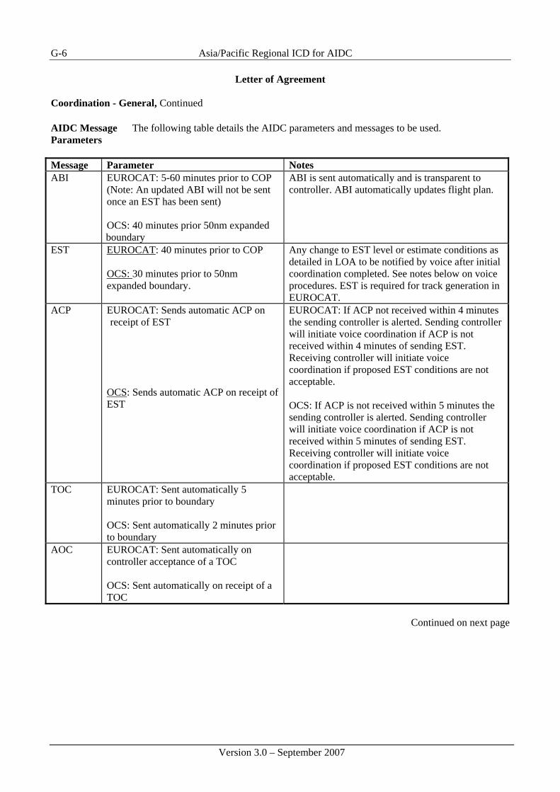
G-6 Asia/Pacific Regional ICD for AIDC
Version 3.0 – September 2007
Letter of Agreement Coordination - General, Continued AIDC Message Parameters
The following table details the AIDC parameters and messages to be used.
Message Parameter Notes ABI EUROCAT: 5-60 minutes prior to COP
(Note: An updated ABI will not be sent once an EST has been sent) OCS: 40 minutes prior 50nm expanded boundary
ABI is sent automatically and is transparent to controller. ABI automatically updates flight plan.
EST EUROCAT: 40 minutes prior to COP OCS: 30 minutes prior to 50nm expanded boundary.
Any change to EST level or estimate conditions as detailed in LOA to be notified by voice after initial coordination completed. See notes below on voice procedures. EST is required for track generation in EUROCAT.
ACP EUROCAT: Sends automatic ACP on receipt of EST
OCS: Sends automatic ACP on receipt of EST
EUROCAT: If ACP not received within 4 minutes the sending controller is alerted. Sending controller will initiate voice coordination if ACP is not received within 4 minutes of sending EST. Receiving controller will initiate voice coordination if proposed EST conditions are not acceptable. OCS: If ACP is not received within 5 minutes the sending controller is alerted. Sending controller will initiate voice coordination if ACP is not received within 5 minutes of sending EST. Receiving controller will initiate voice coordination if proposed EST conditions are not acceptable.
TOC EUROCAT: Sent automatically 5 minutes prior to boundary OCS: Sent automatically 2 minutes prior to boundary
AOC
EUROCAT: Sent automatically on controller acceptance of a TOC OCS: Sent automatically on receipt of a TOC
Continued on next page

Asia/Pacific Regional ICD for AIDC G-7
Version 3.0 – September 2007
Letter of Agreement Coordination – General, Continued AIDC Message Parameters (continued) Message Parameter Notes CDN EUROCAT: Manually by the
controller when required. • Responses to the CDN shall be ACP or REJ only – there
will be no CDN negotiations. • CDN messages will be sent by Brisbane only to revise
coordination on eastbound flights • CDN messages may be used to coordinate changes to
estimate or assigned altitude only • Only one CDN dialogue may be open per aircraft at any
time • Not to be used if the aircraft will not be maintaining the
assigned altitude 10 minutes prior to the TCP. MAC As per ICD LRM
As per ICD. Controller alerted on receipt
LAM
As per ICD. Controller alerted on non-receipt
Amendment to Flight Data Record
Route amendment – routes/waypoints may be added/deleted as long as they do not change the original intent or integrity of the flight plan information. Truncation – where route amendment outside the FIR is unavoidable:
a) Terminate the route details at the farthest possible ‘flight planned’ point of the flight outside the FIR and enter “T” immediately following this.
b) If insufficient ‘flight planned’ points exist outside the FIR for truncation, insert the first ‘defined’ point in the adjoining FIR and enter “T” immediately following this.
c) The minimum acceptable truncation point must be at least the first point in the adjoining FIR.
d) Every effort is to be made to truncate the route at a minimum of one point beyond the adjacent international FIR to provide an entry track in to that FIR.
Continued on next page

G-8 Asia/Pacific Regional ICD for AIDC
Version 3.0 – September 2007
Letter of Agreement Coordination – General, Continued Address Forwarding and Next Data Authority
Brisbane ATSC and Auckland OAC shall send automatic Next Data Authority (NDA) and Address Forwarding (CAD) for data link aircraft as per the following table:
Brisbane ATSC Auto NDA sent 22 minutes prior to the FIR boundary
Auto CAD sent 20 minutes prior to the FIR boundary Auckland OAC Auto NDA sent 40 minutes prior to the FIR boundary
Auto CAD sent 35 minutes prior to the FIR boundary
Voice Coordination
Voice coordination is not required when AIDC messaging has been successful to offer and accept transfer of control. However, the receiving controller will initiate voice coordination if the proposed AIDC EST conditions are not acceptable. If AIDC messaging is not to be sent following voice coordination, it shall be stated as part of the voice coordination by use of the phrase “AIDC messaging will not be sent”. A readback of the phrase is required. Voice coordination is required for aircraft operating under any of the following conditions: • block level clearance; • weather deviations; • offset track; or • Mach Number technique. Readbacks shall comprise all elements of the voice coordination passed by the transferring controller. Readback by the receiving unit confirms acceptance of the offer of transfer of control, subject to any other conditions negotiated.
Hemstitch Flights
A hemstitch flight is any flight that will remain within the New Zealand FIR for less time than the NDA VSP (40 minutes) prior to the flight entering the Brisbane FIR. Auckland AOC shall voice coordinate any hemstitch flight.
Continued on next page

Asia/Pacific Regional ICD for AIDC G-9
Version 3.0 – September 2007
Letter of Agreement Coordination – General, Continued
Near Boundary Operations
ATS units shall relay significant details of any flight which is, or intends, operating within fifty nautical miles (50NM) of the common FIR boundary.
HF Frequencies Brisbane ATC and Auckland ATC shall update each other as to the current voice
backup frequency for use by ATC data link equipped aircraft.

Asia/Pacific Regional ICD for AIDC
Version 3.0 – September 2007
G-10
Template 3 Example: Auckland Oceanic - Nadi ATM Operations Centre
Memorandum of Understanding
Between Airways New Zealand Limited
And Nadi ATM Operations Centre
Subject Air Traffic Service Inter-facility Data Communications (AIDC) Coordination
Procedures
Validity Period This Memorandum of Understanding shall be effective from 0506300300 UTC and may
be cancelled by either party with written notice.
Signatories The following signatories have ratified this Agreement:
Authority Signature Date (Name of Officer) Oceanic Business Unit Manager Airways New Zealand
(Name of Officer) Manager Operations Strategic Air Services Limited Fiji
(Name of Officer) Chairman ATM Projects Committee Airports Fiji Limited Fiji
Continued on next page

Asia/Pacific Regional ICD for AIDC G-11
Version 3.0 – September 2007
Memorandum of Understanding, Continued
Purpose To establish procedures to permit AIDC messages for coordination purposes to be
transmitted by Auckland Oceanic and received by Nadi Air Traffic Management Operations Centre (ATMOC).
Scope This MOU between Auckland and Nadi is supplementary to the procedures contained in
the Airways Corporation of New Zealand limited and Airports Fiji Limited LOA, dated 25 November 2004. Revision to this MOU shall be made only with the concurrence of all parties.
Procedures 8. The format of AIDC messages (ABI, EST, PAC, CDN, CPL, ACP, REJ, TOC,
AOC, MAC, LAM, and LRM) are as defined by the Asia/Pacific Regional AIDC Interface Control Document (ICD) Version 2.0. The optional formats for the coordination of block levels, weather deviations and Mach Number Technique have not been implemented.
9. Each facility shall advise the other facility of any known equipment outage that
affects AIDC. In the event of AIDC outage, voice coordination procedures will apply.
10. The following table details the messaging parameters and additional information for
each message. Messages Parameter Notes ABI Non Hem- stitching flights
Auckland: Sends ABI 48 minutes prior to Boundary (Note: An updated ABI will not be sent once an EST has been sent)
Updated ABI’s will be sent automatically if there is any change to profile. ABI is sent automatically and is transparent to the controller. ABI automatically updates the receiving units flight data record
EST (general) Non Hem- stitching flights
Auckland: Sends EST 38 minutes prior to Boundary
EST is sent automatically, and automatically coordinates the receiving unit’s flight data record. Any change to the EST (level or estimate) conditions as detailed in LOA are to be notified by voice after the initial coordination completed. See section below on voice procedures.
Continued on next page

Asia/Pacific Regional ICD for AIDC
Version 3.0 – September 2007
G-12
Memorandum of Understanding, Continued ABI & EST Hemstitch flights
Auckland: Sends the ABI and EST message for flights that re-enter the Nadi FIR as soon as the aircraft enters the NZZO FIR
In these cases the ABI and EST are sent automatically.
PAC Auckland: Voice coordination will take place in those situations when a PAC is sent.
ACP Auckland: Sent automatically on receipt of EST Nadi: Sent automatically on receipt of EST or PAC.
Auckland: The APS will display a flashing “DIA” until receipt of ACP. If ACP not received within ten (10) minutes controller is alerted with a message to the queue.
TOC Auckland: Sent automatically 2 minutes prior to boundary
This proposes a hand-off to the receiving unit
AOC
Auckland: Sent automatically on receipt of TOC. Nadi: Sent by the controller on acceptance of TOC.
This completes the hand-off proposal.
MAC Auckland: Sent manually when a change to the route makes Nadi no longer the “next” responsible unit.
Receipt of a MAC message should not be interpreted as meaning that the flight plan has been cancelled Voice coordination should be conducted by the receiving controller to confirm the status of the flight.
Continued on next page

Asia/Pacific Regional ICD for AIDC G-13
Version 3.0 – September 2007
Memorandum of Understanding, Continued Procedures Continued
4. Block levels, offsets, and weather deviations, or Mach Number Technique are not included in the current version of AIDC messaging. Voice coordination shall be conducted for aircraft operating under these circumstances.
5. If there is any doubt with regard to the final coordination conditions, voice
coordination shall be used for confirmation. 6. Truncation – Where route amendment outside the FIR is unavoidable:
b) Terminate the route details at the farthest possible ‘flight planned’ point of the flight and enter “T” immediately following this.
c) Without amending the originally received details, every effort is to be made to truncate the route at a minimum of one point beyond the adjacent FIR to provide an entry track in to that FIR.
7. For any reason where changes to this MOU are advisable the requesting unit shall
propose the pertinent revision. The revision should be emailed or faxed to the appropriate Manager for action. The Manager or their designated deputies shall agree by email or telephone, followed by a confirming fax message signed by all parties. Formal exchange of signed copies of the amended MOU shall take place as soon as practicable thereafter.
Continued on next page

Asia/Pacific Regional ICD for AIDC
Version 3.0 – September 2007
G-14
Memorandum of Understanding, Continued Hemstitch Flights
A hemstitch flight is any flight that vacates FIR 1 and transits FIR 2, before re-entering FIR1. When a hemstitching flight vacates FIR 1 and then re-enters FIR 1 from FIR 2, 30 mins or less later, the re-entry coordination is considered to have been completed when coordination for the initial entry is completed and further coordination is only required if the aircraft requests
• A weather deviation or • A level change or • Any change to the EST time is received or • If there is any doubt that the receiving FIR has the correct boundary information.
AIDC messages (ABI and EST) will still be sent by Auckland but only when the aircraft flight state becomes active control. For hem stitching flights this will usually be when the aircraft enters the NZZO FIR, therefore these messages will normally be sent at less than 30 minutes prior to the TCP.
Continued on next page

Asia/Pacific Regional ICD for AIDC G-15
Version 3.0 – September 2007
Memorandum of Understanding, Continued Voice Coordination
The following is provided as a summary of occasions when voice coordination is required: • In the event of an AIDC outage; • Aircraft operating under any of the following conditions:
• block level clearance; • unfulfilled time constraints; • weather deviations; • offset track; or • Mach Number technique.
• Any change to the EST (level or time) conditions • On receipt of a warning that an ACP has not been received; • On receipt of a MAC message; • If there is any doubt with regard to the final coordination conditions • If the receiving controller can not accept the aircraft at the coordinated level; Notwithstanding the above, voice coordination shall take place for any flight that departs an airfield within the NZZO FIR and enters the NFFF FIR within 30 mins after departure. For aircraft on fixed routes this specifically applies to :
• Aircraft departing Norfolk and entering the Nadi FIR via UBDAK or OSVAR; • Aircraft departing Fua’amotu and entering the Nadi FIR via APASI; • Aircraft departing Faleolo and entering the Nadi FIR via OVLAD or KETOT
Auckland OCA will obtain the appropriate level approval for these flights and will pass Nadi an “Estimate” based on the aircrafts probed profile at the same time as obtaining the level approval. A PAC message will also be sent containing the time at the TCP and the climbing condition. Time revisions will only be passed when the “Estimated” time changes by more than 2 minutes from that previously passed. Level changes to that previously coordinated and/or off track requests shall be verbally coordinated in the usual manner.
.
Continued on next page

Asia/Pacific Regional ICD for AIDC
Version 3.0 – September 2007
G-16
Memorandum of Understanding, Continued Notification of Descent Restrictions by Nadi
Auckland OCS controllers may issue descent to aircraft entering the NZZO FIR from the NFFF FIR and landing at Norfolk, Tonga or Samoa without requesting descent restrictions from Nadi provided descent is commenced after the aircraft has passed the following positions. Should Nadi have any restrictions for descent they will advise Auckland at least 10 mins prior to these positions. For aircraft entering the NZZO FIR via: • UPDAK descent to commence after NOGOL • OSVAR descent to commence after OSVAR minus 10 mins • APASI descent to commence after APASI • All other occasions’ descent to commence after the aircraft has crossed the FIR
boundary.