Internal RS-232 Interface for XHR/XFR Series · Product Family: Internal RS-232 Interface for...
58
TM-RSRF-01XN Rev B www.programmablepower.com Internal RS-232 Interface for XHR/XFR Series Programmable DC Power Supplies Operating Manual RS232-XHR RS232-XFR RS232-XFR3
Transcript of Internal RS-232 Interface for XHR/XFR Series · Product Family: Internal RS-232 Interface for...
TM-RSRF-01XN Rev B www.programmablepower.com
Internal RS-232 Interface
for XHR/XFR Series Programmable DC Power Supplies
Operating Manual
RS232-XHR RS232-XFR RS232-XFR3

About AMETEK AMETEK Programmable Power, Inc., a Division of AMETEK, Inc., is a global leader in the design and manufacture of precision, programmable power supplies for R&D, test and measurement, process control, power bus simulation and power conditioning applications across diverse industrial segments. From bench top supplies to rack-mounted industrial power subsystems, AMETEK Programmable Power is the proud manufacturer of Elgar, Sorensen, California Instruments and Power Ten brand power supplies.
AMETEK, Inc. is a leading global manufacturer of electronic instruments and electromechanical devices with annualized sales of $2.5 billion. The Company has over 11,000 colleagues working at more than 80 manufacturing facilities and more than 80 sales and service centers in the United States and around the world.
Trademarks AMETEK is a registered trademark of AMETEK, Inc. Sorensen is a trademark owned by AMETEK, Inc. Other trademarks, registered trademarks, and product names are the property of their respective owners and are used herein for identification purposes only.
Notice of Copyright Internal RS-232 Interface for XHR/XFR Series Programmable DC Power Supplies Operating Manual © 2007 AMETEK Programmable Power, Inc. All rights reserved.
Exclusion for Documentation UNLESS SPECIFICALLY AGREED TO IN WRITING, AMETEK PROGRAMMABLE POWER, INC. (“AMETEK”):
(a) MAKES NO WARRANTY AS TO THE ACCURACY, SUFFICIENCY OR SUITABILITY OF ANY TECHNICAL OR OTHER INFORMATION PROVIDED IN ITS MANUALS OR OTHER DOCUMENTATION.
(b) ASSUMES NO RESPONSIBILITY OR LIABILITY FOR LOSSES, DAMAGES, COSTS OR EXPENSES, WHETHER SPECIAL, DIRECT, INDIRECT, CONSEQUENTIAL OR INCIDENTAL, WHICH MIGHT ARISE OUT OF THE USE OF SUCH INFORMATION. THE USE OF ANY SUCH INFORMATION WILL BE ENTIRELY AT THE USER’S RISK, AND
(c) REMINDS YOU THAT IF THIS MANUAL IS IN ANY LANGUAGE OTHER THAN ENGLISH, ALTHOUGH STEPS HAVE BEEN TAKEN TO MAINTAIN THE ACCURACY OF THE TRANSLATION, THE ACCURACY CANNOT BE GUARANTEED. APPROVED AMETEK CONTENT IS CONTAINED WITH THE ENGLISH LANGUAGE VERSION, WHICH IS POSTED AT WWW.PROGRAMMABLEPOWER.COM.
Date and Revision February 2009 Revision B
Part Number TM-RSRF-01XN
Contact Information Telephone: 800 733 5427 (toll free in North America) 858 450 0085 (direct) Fax: 858 458 0267 Email: [email protected] [email protected] Web: www.programmablepower.com
i

This page intentionally left blank.
ii
Important Safety Instructions Before applying power to the system, verify that your product is configured properly for your particular application.
WARNING
Hazardous voltages may be present when covers are removed. Qualified personnel must use extreme caution when servicing this equipment. Circuit boards, test points, and output voltages also may be floating above (below) chassis ground.
WARNING
The equipment used contains ESD sensitive parts. When installing equipment, follow ESD Safety Procedures. Electrostatic discharges might cause damage to the equipment.
Only qualified personnel who deal with attendant hazards in power supplies, are allowed to perform installation and servicing. Ensure that the AC power line ground is connected properly to the Power Rack input connector or chassis. Similarly, other power ground lines including those to application and maintenance equipment must be grounded properly for both personnel and equipment safety. Always ensure that facility AC input power is de-energized prior to connecting or disconnecting any cable. In normal operation, the operator does not have access to hazardous voltages within the chassis. However, depending on the user’s application configuration, HIGH VOLTAGES HAZARDOUS TO HUMAN SAFETY may be normally generated on the output terminals. The customer/user must ensure that the output power lines are labeled properly as to the safety hazards and that any inadvertent contact with hazardous voltages is eliminated. Guard against risks of electrical shock during open cover checks by not touching any portion of the electrical circuits. Even when power is off, capacitors may retain an electrical charge. Use safety glasses during open cover checks to avoid personal injury by any sudden component failure. Neither AMETEK Programmable Power Inc., San Diego, California, USA, nor any of the subsidiary sales organizations can accept any responsibility for personnel, material or inconsequential injury, loss or damage that results from improper use of the equipment and accessories.
iii
Product Family: Internal RS-232 Interface for XHR/XFR Series
Warranty Period: Five Years
WARRANTY TERMS AMETEK Programmable Power, Inc. (“AMETEK”), provides this written warranty covering the Product stated above, and if the Buyer discovers and notifies AMETEK in writing of any defect in material or workmanship within the applicable warranty period stated above, then AMETEK may, at its option: repair or replace the Product; or issue a credit note for the defective Product; or provide the Buyer with replacement parts for the Product.
The Buyer will, at its expense, return the defective Product or parts thereof to AMETEK in accordance with the return procedure specified below. AMETEK will, at its expense, deliver the repaired or replaced Product or parts to the Buyer. Any warranty of AMETEK will not apply if the Buyer is in default under the Purchase Order Agreement or where the Product or any part thereof:
• is damaged by misuse, accident, negligence or failure to maintain the same as specified or required by AMETEK;
• is damaged by modifications, alterations or attachments thereto which are not authorized by AMETEK;
• is installed or operated contrary to the instructions of AMETEK; • is opened, modified or disassembled in any way without AMETEK’s consent; or • is used in combination with items, articles or materials not authorized by
AMETEK.
The Buyer may not assert any claim that the Products are not in conformity with any warranty until the Buyer has made all payments to AMETEK provided for in the Purchase Order Agreement.
PRODUCT RETURN PROCEDURE
1. Request a Return Material Authorization (RMA) number from the repair facility (must be done in the country in which it was purchased): • In the USA, contact the AMETEK Repair Department prior to the return of the
product to AMETEK for repair: Telephone: 800-733-5427, ext. 2295 or ext. 2463 (toll free North America) 858-450-0085, ext. 2295 or ext. 2463 (direct)
• Outside the United States, contact the nearest Authorized Service Center (ASC). A full listing can be found either through your local distributor or our website, www.programmablepower.com, by clicking Support and going to the Service Centers tab.
2. When requesting an RMA, have the following information ready: • Model number • Serial number • Description of the problem
NOTE: Unauthorized returns will not be accepted and will be returned at the shipper’s expense.
NOTE: A returned product found upon inspection by AMETEK, to be in specification is subject to an evaluation fee and applicable freight charges.
iv
ContentsSection 1.
Features andSpecifications
Description . . . . . . . . . . . . . . . . . . . . . . . . . . . . . . . . . . . . . . . . . . . . . . . . . . . . . . . . . 11Features and Functions . . . . . . . . . . . . . . . . . . . . . . . . . . . . . . . . . . . . . . . . . . . . . . . 12
Features. . . . . . . . . . . . . . . . . . . . . . . . . . . . . . . . . . . . . . . . . . . . . . . . . . . . . . . 12Programmable Functions . . . . . . . . . . . . . . . . . . . . . . . . . . . . . . . . . . . . . . . . . . 12Readback Functions . . . . . . . . . . . . . . . . . . . . . . . . . . . . . . . . . . . . . . . . . . . . . 12
Specifications . . . . . . . . . . . . . . . . . . . . . . . . . . . . . . . . . . . . . . . . . . . . . . . . . . . . . . . 13
Section 2.Installation
andConfiguration
Introduction . . . . . . . . . . . . . . . . . . . . . . . . . . . . . . . . . . . . . . . . . . . . . . . . . . . . . . . . . 19Initial Inspection . . . . . . . . . . . . . . . . . . . . . . . . . . . . . . . . . . . . . . . . . . . . . . . . . . . . . 19Basic Setup Procedure . . . . . . . . . . . . . . . . . . . . . . . . . . . . . . . . . . . . . . . . . . . . . . . . 23Communications . . . . . . . . . . . . . . . . . . . . . . . . . . . . . . . . . . . . . . . . . . . . . . . . . . . . . 24
Baud Rate Selection . . . . . . . . . . . . . . . . . . . . . . . . . . . . . . . . . . . . . . . . . . . . . 24Flow Control Selection . . . . . . . . . . . . . . . . . . . . . . . . . . . . . . . . . . . . . . . . . . . . 24Software Flow Control . . . . . . . . . . . . . . . . . . . . . . . . . . . . . . . . . . . . . . . . . . . . 25Hardware Flow Control . . . . . . . . . . . . . . . . . . . . . . . . . . . . . . . . . . . . . . . . . . . 25Connections . . . . . . . . . . . . . . . . . . . . . . . . . . . . . . . . . . . . . . . . . . . . . . . . . . . . 26Transmit / Receive Pin Selection . . . . . . . . . . . . . . . . . . . . . . . . . . . . . . . . . . . . 26
Remote/Local Operation. . . . . . . . . . . . . . . . . . . . . . . . . . . . . . . . . . . . . . . . . . . . . . . 27Remote / Local Mode Startup . . . . . . . . . . . . . . . . . . . . . . . . . . . . . . . . . . . . . . 27Remote Mode Operation . . . . . . . . . . . . . . . . . . . . . . . . . . . . . . . . . . . . . . . . . . 28Local Mode Operation . . . . . . . . . . . . . . . . . . . . . . . . . . . . . . . . . . . . . . . . . . . . 29Remote Enable (REN) Command . . . . . . . . . . . . . . . . . . . . . . . . . . . . . . . . . . . 29Local Lockout (LLO) Command . . . . . . . . . . . . . . . . . . . . . . . . . . . . . . . . . . . . . 30
RS-232 Connection . . . . . . . . . . . . . . . . . . . . . . . . . . . . . . . . . . . . . . . . . . . . . . . . . . 30Power Supply Settings . . . . . . . . . . . . . . . . . . . . . . . . . . . . . . . . . . . . . . . . . . . . . . . . 31User Options and Settings . . . . . . . . . . . . . . . . . . . . . . . . . . . . . . . . . . . . . . . . . . . . . 32
OVP Selection . . . . . . . . . . . . . . . . . . . . . . . . . . . . . . . . . . . . . . . . . . . . . . . . . . 32TTL Shutdown . . . . . . . . . . . . . . . . . . . . . . . . . . . . . . . . . . . . . . . . . . . . . . . . . . 33
User Signals . . . . . . . . . . . . . . . . . . . . . . . . . . . . . . . . . . . . . . . . . . . . . . . . . . . . . . . . 34Connector J7 User Signals . . . . . . . . . . . . . . . . . . . . . . . . . . . . . . . . . . . . . . . . 34J7 Cable Connection . . . . . . . . . . . . . . . . . . . . . . . . . . . . . . . . . . . . . . . . . . . . . 35
Section 3.Operation
Introduction . . . . . . . . . . . . . . . . . . . . . . . . . . . . . . . . . . . . . . . . . . . . . . . . . . . . . . . . . 37RS-232 Operation. . . . . . . . . . . . . . . . . . . . . . . . . . . . . . . . . . . . . . . . . . . . . . . . . . . . 37Command Syntax . . . . . . . . . . . . . . . . . . . . . . . . . . . . . . . . . . . . . . . . . . . . . . . . . . . . 37
Manual Conventions . . . . . . . . . . . . . . . . . . . . . . . . . . . . . . . . . . . . . . . . . . . . . 37Command Format and Parameters . . . . . . . . . . . . . . . . . . . . . . . . . . . . . . . . . . 38Command Strings . . . . . . . . . . . . . . . . . . . . . . . . . . . . . . . . . . . . . . . . . . . . . . . 39Command Terminators . . . . . . . . . . . . . . . . . . . . . . . . . . . . . . . . . . . . . . . . . . . 40Order . . . . . . . . . . . . . . . . . . . . . . . . . . . . . . . . . . . . . . . . . . . . . . . . . . . . . . . . . 40
Command Summary. . . . . . . . . . . . . . . . . . . . . . . . . . . . . . . . . . . . . . . . . . . . . . . . . . 41Command Reference . . . . . . . . . . . . . . . . . . . . . . . . . . . . . . . . . . . . . . . . . . . . . . . . . 44
v
Contents
Accumulated Status, Status, and Fault Registers . . . . . . . . . . . . . . . . . . . . . . . . . . . 51Error Codes . . . . . . . . . . . . . . . . . . . . . . . . . . . . . . . . . . . . . . . . . . . . . . . . . . . . . . . . 53Troubleshooting . . . . . . . . . . . . . . . . . . . . . . . . . . . . . . . . . . . . . . . . . . . . . . . . . . . . . 54
Diagnostic LEDs . . . . . . . . . . . . . . . . . . . . . . . . . . . . . . . . . . . . . . . . . . . . . . . . 54
Section 4.Calibration
Introduction . . . . . . . . . . . . . . . . . . . . . . . . . . . . . . . . . . . . . . . . . . . . . . . . . . . . . . . . 55Voltage Mode Calibration. . . . . . . . . . . . . . . . . . . . . . . . . . . . . . . . . . . . . . . . . . . . . . 56
Voltage Calibration Setup . . . . . . . . . . . . . . . . . . . . . . . . . . . . . . . . . . . . . . . . . 56Voltage Program Calibration Procedure . . . . . . . . . . . . . . . . . . . . . . . . . . . . . . 56Voltage Readback Calibration Procedure . . . . . . . . . . . . . . . . . . . . . . . . . . . . . 57
Current Mode Calibration. . . . . . . . . . . . . . . . . . . . . . . . . . . . . . . . . . . . . . . . . . . . . . 58Current Calibration Setup . . . . . . . . . . . . . . . . . . . . . . . . . . . . . . . . . . . . . . . . . 58Current Program Calibration Procedure . . . . . . . . . . . . . . . . . . . . . . . . . . . . . . 58Current Readback Calibration Procedure . . . . . . . . . . . . . . . . . . . . . . . . . . . . . 59
Over Voltage Protection (OVP) Calibration . . . . . . . . . . . . . . . . . . . . . . . . . . . . . . . . 60
vi Operating Manual for RS-232 for XHR/XFR Series Power Supply
11
Section 1. Features and Specifications
Description
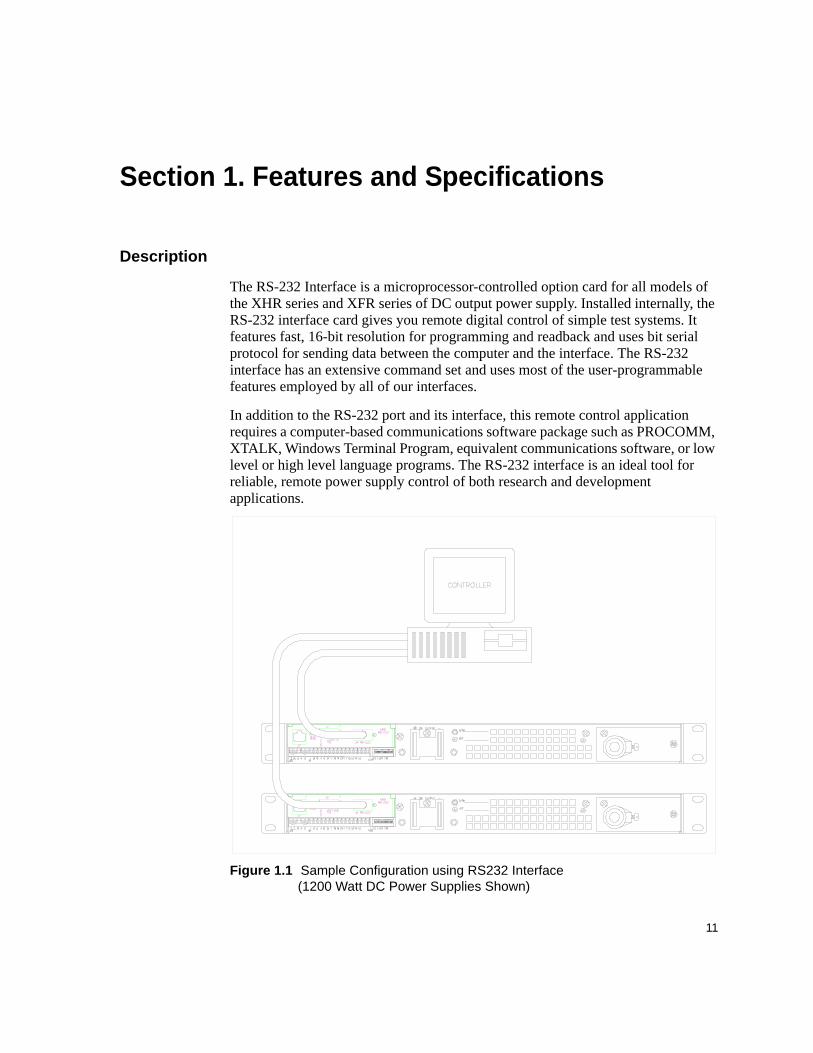
The RS-232 Interface is a microprocessor-controlled option card for all models of the XHR series and XFR series of DC output power supply. Installed internally, the RS-232 interface card gives you remote digital control of simple test systems. It features fast, 16-bit resolution for programming and readback and uses bit serial protocol for sending data between the computer and the interface. The RS-232 interface has an extensive command set and uses most of the user-programmable features employed by all of our interfaces.
In addition to the RS-232 port and its interface, this remote control application requires a computer-based communications software package such as PROCOMM, XTALK, Windows Terminal Program, equivalent communications software, or low level or high level language programs. The RS-232 interface is an ideal tool for reliable, remote power supply control of both research and development applications.
Figure 1.1 Sample Configuration using RS232 Interface(1200 Watt DC Power Supplies Shown)
Features and SpecificationsFeatures and Functions
12 Operating Manual for RS-232 for XHR/XFR Series Power Supply
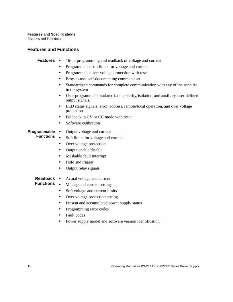
Features and Functions
Features • 16-bit programming and readback of voltage and current• Programmable soft limits for voltage and current• Programmable over voltage protection with reset• Easy-to-use, self-documenting command set• Standardized commands for complete communication with any of the supplies
in the system• User-programmable isolated fault, polarity, isolation, and auxiliary, user-defined
output signals.• LED status signals: error, address, remote/local operation, and over voltage
protection.• Foldback in CV or CC mode with reset• Software calibration
ProgrammableFunctions
• Output voltage and current• Soft limits for voltage and current• Over voltage protection• Output enable/disable• Maskable fault interrupt• Hold and trigger• Output relay signals
ReadbackFunctions
• Actual voltage and current• Voltage and current settings• Soft voltage and current limits• Over voltage protection setting• Present and accumulated power supply status• Programming error codes• Fault codes• Power supply model and software version identification
Features and SpecificationsSpecifications
13
Specifications
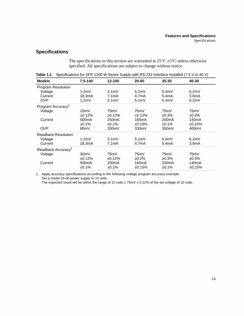
The specifications in this section are warranted at 25°C ±5°C unless otherwise specified. All specifications are subject to change without notice.
Table 1.1 Specifications for XFR 1200 W Series Supply with RS-232 Interface Installed (7.5 V to 40 V) Models 7.5-140 12-100 20-60 35-35 40-30Program Resolution
VoltageCurrentOVP
1.2mV18.3mA1.2mV
3.1mV7.1mA3.1mV
5.1mV4.7mA5.1mV
5.4mV5.4mA5.4mV
6.2mV3.6mA6.2mV
Program Accuracy1
Voltage
Current
OVP
1. Apply accuracy specifications according to the following voltage program accuracy example:Set a model 20-60 power supply to 10 volts.The expected result will be within the range of 10 volts ± 75mV ± 0.12% of the set voltage of 10 volts.
10mV ±0.12%500mA ±0.1%80mV
75mV±0.12%250mA ±0.1%200mV
75mV±0.12%165mA ±0.15%330mV
75mV±0.3%200mA ±0.1%350mV
75mV±0.3%140mA ±0.15%400mV
Readback ResolutionVoltageCurrent
1.2mV18.3mA
3.1mV7.1mA
5.1mV4.7mA
5.4mV5.4mA
6.2mV3.6mA
Readback Accuracy1
Voltage
Current
30mV±0.12%500mA ±0.1%
75mV±0.12%250mA ±0.1%
75mV±0.2%165mA ±0.15%
75mV±0.3%200mA ±0.1%
75mV±0.3%140mA ±0.15%
Features and SpecificationsSpecifications
14 Operating Manual for RS-232 for XHR/XFR Series Power Supply
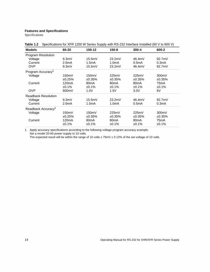
Table 1.2 Specifications for XFR 1200 W Series Supply with RS-232 Interface Installed (60 V to 600 V)Models 60-20 100-12 150-8 300-4 600-2Program Resolution
VoltageCurrentOVP
9.3mV2.6mA9.3mV
15.5mV1.5mA15.5mV
23.2mV1.0mA23.2mV
46.4mV0.5mA46.4mV
92.7mV0.3mA92.7mV
Program Accuracy1
Voltage
Current
OVP
1. Apply accuracy specifications according to the following voltage program accuracy example:Set a model 20-60 power supply to 10 volts.The expected result will be within the range of 10 volts ± 75mV ± 0.12% of the set voltage of 10 volts.
150mV±0.25%120mA ±0.1%600mV
150mV±0.35%80mA ±0.1%1.0V
225mV±0.35%80mA ±0.1%1.5V
225mV±0.35%80mA ±0.1%3.0V
300mV±0.35%75mA ±0.1%6V
Readback ResolutionVoltageCurrent
9.3mV2.6mA
15.5mV1.5mA
23.2mV1.0mA
46.4mV0.5mA
92.7mV0.3mA
Readback Accuracy1
Voltage
Current
150mV±0.25%120mA ±0.1%
150mV±0.35%80mA ±0.1%
225mV±0.35%80mA ±0.1%
225mV±0.35%80mA ±0.1%
300mV±0.35%75mA ±0.1%
Features and SpecificationsSpecifications
15
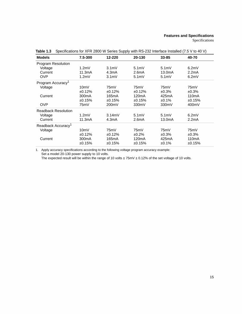
Table 1.3 Specifications for XFR 2800 W Series Supply with RS-232 Interface Installed (7.5 V to 40 V)Models 7.5-300 12-220 20-130 33-85 40-70Program Resolution
VoltageCurrentOVP
1.2mV11.3mA1.2mV
3.1mV4.3mA3.1mV
5.1mV2.6mA5.1mV
5.1mV13.0mA5.1mV
6.2mV2.2mA6.2mV
Program Accuracy1
Voltage
Current
OVP
10mV ±0.12%300mA ±0.15%75mV
75mV±0.12%165mA ±0.15%200mV
75mV±0.12%120mA ±0.15%330mV
75mV±0.3%425mA ±0.1%330mV
75mV±0.3%110mA ±0.15%400mV
Readback ResolutionVoltageCurrent
1.2mV11.3mA
3.14mV4.3mA
5.1mV2.6mA
5.1mV13.0mA
6.2mV2.2mA
Readback Accuracy1
Voltage
Current
1. Apply accuracy specifications according to the following voltage program accuracy example:Set a model 20-130 power supply to 10 volts.The expected result will be within the range of 10 volts ± 75mV ± 0.12% of the set voltage of 10 volts.
10mV±0.12%300mA ±0.15%
75mV±0.12%165mA ±0.15%
75mV±0.2%120mA ±0.15%
75mV±0.3%425mA ±0.1%
75mV±0.3%110mA ±0.15%
Features and SpecificationsSpecifications
16 Operating Manual for RS-232 for XHR/XFR Series Power Supply
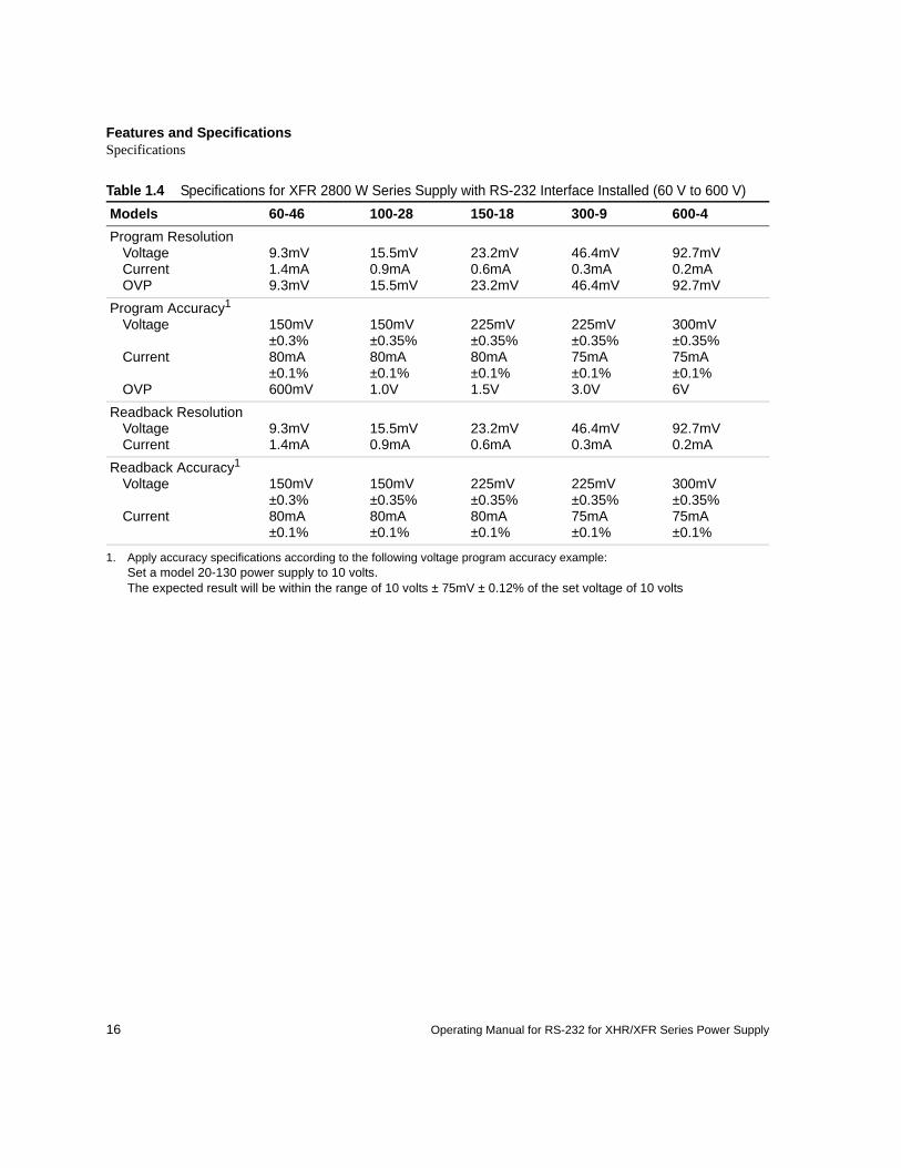
Table 1.4 Specifications for XFR 2800 W Series Supply with RS-232 Interface Installed (60 V to 600 V)Models 60-46 100-28 150-18 300-9 600-4Program Resolution
VoltageCurrentOVP
9.3mV1.4mA9.3mV
15.5mV0.9mA15.5mV
23.2mV0.6mA23.2mV
46.4mV0.3mA46.4mV
92.7mV0.2mA92.7mV
Program Accuracy1
Voltage
Current
OVP
1. Apply accuracy specifications according to the following voltage program accuracy example:Set a model 20-130 power supply to 10 volts.The expected result will be within the range of 10 volts ± 75mV ± 0.12% of the set voltage of 10 volts
150mV±0.3%80mA ±0.1%600mV
150mV±0.35%80mA ±0.1%1.0V
225mV±0.35%80mA ±0.1%1.5V
225mV±0.35%75mA ±0.1%3.0V
300mV±0.35%75mA ±0.1%6V
Readback ResolutionVoltageCurrent
9.3mV1.4mA
15.5mV0.9mA
23.2mV0.6mA
46.4mV0.3mA
92.7mV0.2mA
Readback Accuracy1
Voltage
Current
150mV±0.3%80mA ±0.1%
150mV±0.35%80mA ±0.1%
225mV±0.35%80mA ±0.1%
225mV±0.35%75mA ±0.1%
300mV±0.35%75mA ±0.1%
Features and SpecificationsSpecifications
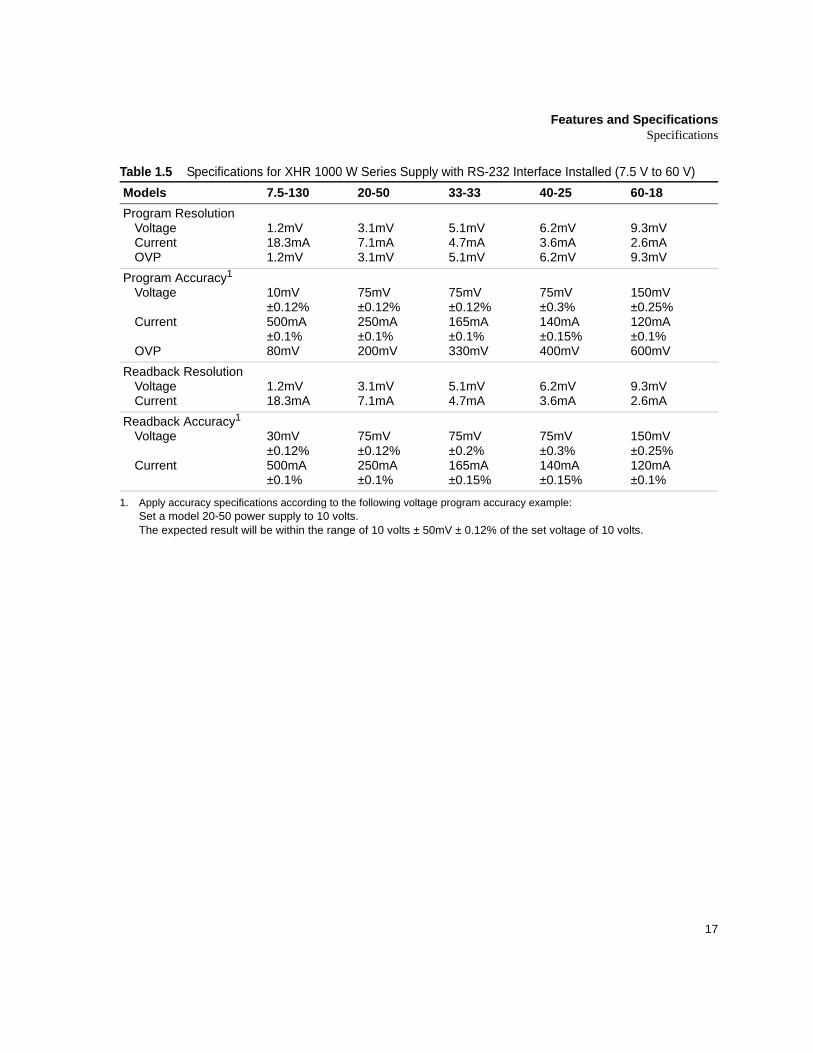
17
Table 1.5 Specifications for XHR 1000 W Series Supply with RS-232 Interface Installed (7.5 V to 60 V)Models 7.5-130 20-50 33-33 40-25 60-18Program Resolution
VoltageCurrentOVP
1.2mV18.3mA1.2mV
3.1mV7.1mA3.1mV
5.1mV4.7mA5.1mV
6.2mV3.6mA6.2mV
9.3mV2.6mA9.3mV
Program Accuracy1
Voltage
Current
OVP
1. Apply accuracy specifications according to the following voltage program accuracy example:Set a model 20-50 power supply to 10 volts.The expected result will be within the range of 10 volts ± 50mV ± 0.12% of the set voltage of 10 volts.
10mV ±0.12%500mA ±0.1%80mV
75mV±0.12%250mA ±0.1%200mV
75mV±0.12%165mA ±0.1%330mV
75mV±0.3%140mA ±0.15%400mV
150mV±0.25%120mA ±0.1%600mV
Readback ResolutionVoltageCurrent
1.2mV18.3mA
3.1mV7.1mA
5.1mV4.7mA
6.2mV3.6mA
9.3mV2.6mA
Readback Accuracy1
Voltage
Current
30mV±0.12%500mA ±0.1%
75mV±0.12%250mA ±0.1%
75mV±0.2%165mA ±0.15%
75mV±0.3%140mA ±0.15%
150mV±0.25%120mA ±0.1%
Features and SpecificationsSpecifications
18 Operating Manual for RS-232 for XHR/XFR Series Power Supply
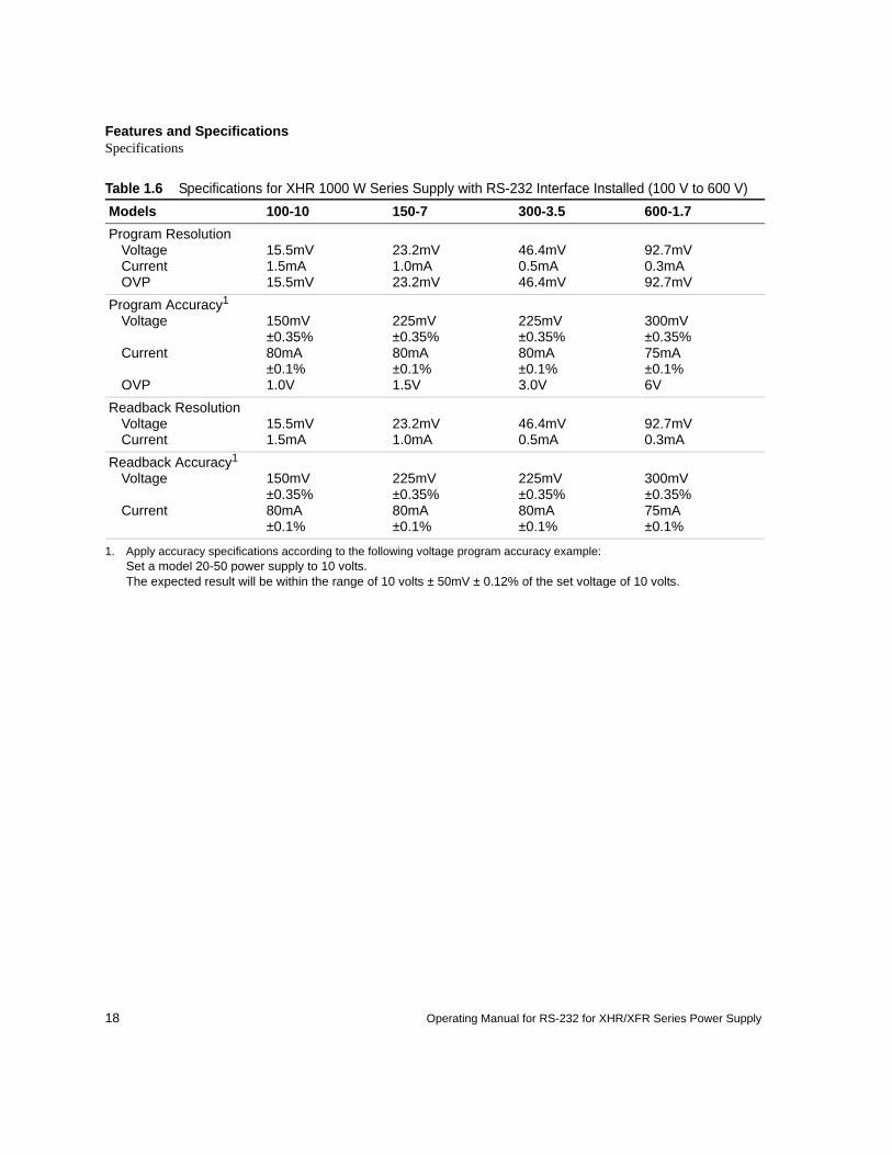
Table 1.6 Specifications for XHR 1000 W Series Supply with RS-232 Interface Installed (100 V to 600 V)Models 100-10 150-7 300-3.5 600-1.7Program Resolution
VoltageCurrentOVP
15.5mV1.5mA15.5mV
23.2mV1.0mA23.2mV
46.4mV0.5mA46.4mV
92.7mV0.3mA92.7mV
Program Accuracy1
Voltage
Current
OVP
1. Apply accuracy specifications according to the following voltage program accuracy example:Set a model 20-50 power supply to 10 volts.The expected result will be within the range of 10 volts ± 50mV ± 0.12% of the set voltage of 10 volts.
150mV±0.35%80mA ±0.1%1.0V
225mV±0.35%80mA ±0.1%1.5V
225mV±0.35%80mA ±0.1%3.0V
300mV±0.35%75mA ±0.1%6V
Readback ResolutionVoltageCurrent
15.5mV1.5mA
23.2mV1.0mA
46.4mV0.5mA
92.7mV0.3mA
Readback Accuracy1
Voltage
Current
150mV±0.35%80mA ±0.1%
225mV±0.35%80mA ±0.1%
225mV±0.35%80mA ±0.1%
300mV±0.35%75mA ±0.1%

19
Section 2. Installation and Configuration
Introduction
To use this product, you must have the following equipment:• a compatible model of DC output power supply• serial extender cable (straight through)• computer with an RS-232 interface (serial port)• computer-based communications software package
The RS-232 interface is usually installed at the factory. Your local distributor or service center can also install the interface, especially for use in a previously-purchased supply already on site. You must then configure the RS-232 Interface-enhanced supply for your system using the “Basic Setup Procedure” on page 23. Refer also to Figure 2.1, on page 20, Figure 2.2, on page 21 and Figure 2.3, on page 22 for drawings of the front panel, the interface subplate, and the RS-232 interface printed circuit board (PCB).
Initial Inspection
On first receiving your unit, perform a quick physical check. • Ensure each package contains a power supply with its RS-232 interface board
installed, and manuals for the power supply and the RS-232 interface. Any additional parts shipped with the power supply will be identified in the supply's documentation.
• Inspect the unit for any signs of physical damage such as scratches, cracks, or broken switches, connectors, or displays.
• Check the printed circuit board and components if you suspect internal damage.
If the unit is damaged, save all packing materials and notify the carrier immediately. For additional information, please see the section titles, “Returning Power Supplies to the Manufacturer” in the manual shipped with your complete unit.
!CAUTIONIf you remove the unit's cover, use proper static control techniques to avoid damage to static-sensitive components on the printed circuit board.
Installation and ConfigurationInitial Inspection
20 Operating Manual for RS-232 for XHR/XFR Series Power Supply
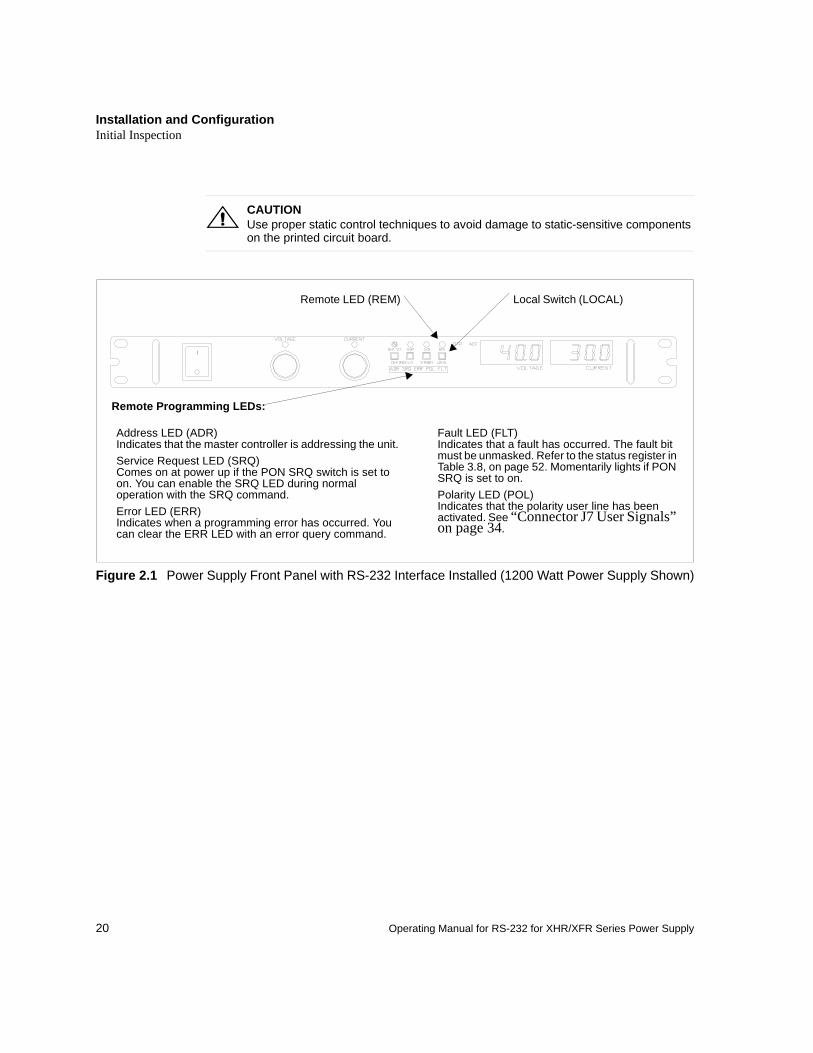
Figure 2.1 Power Supply Front Panel with RS-232 Interface Installed (1200 Watt Power Supply Shown)
!CAUTIONUse proper static control techniques to avoid damage to static-sensitive components on the printed circuit board.
Address LED (ADR)Indicates that the master controller is addressing the unit.Service Request LED (SRQ)Comes on at power up if the PON SRQ switch is set to on. You can enable the SRQ LED during normal operation with the SRQ command.Error LED (ERR)Indicates when a programming error has occurred. You can clear the ERR LED with an error query command.
Fault LED (FLT)Indicates that a fault has occurred. The fault bit must be unmasked. Refer to the status register in Table 3.8, on page 52. Momentarily lights if PON SRQ is set to on.Polarity LED (POL)Indicates that the polarity user line has been activated. See “Connector J7 User Signals” on page 34.
Local Switch (LOCAL)Remote LED (REM)
Remote Programming LEDs:
Installation and ConfigurationInitial Inspection
21
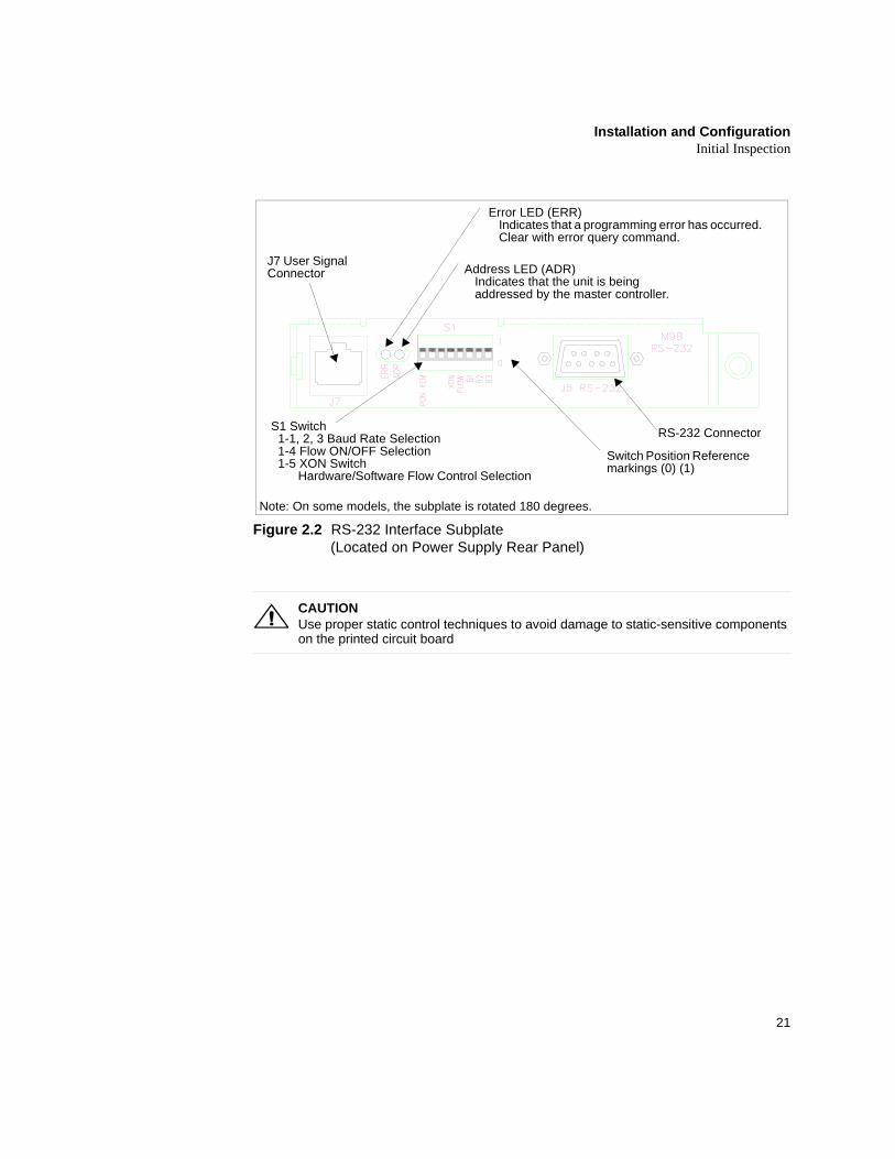
Figure 2.2 RS-232 Interface Subplate (Located on Power Supply Rear Panel)
!CAUTIONUse proper static control techniques to avoid damage to static-sensitive components on the printed circuit board
S1 Switch 1-1, 2, 3 Baud Rate Selection 1-4 Flow ON/OFF Selection 1-5 XON Switch Hardware/Software Flow Control Selection
Error LED (ERR)Indicates that a programming error has occurred. Clear with error query command.
J7 User Signal Connector
RS-232 Connector
Note: On some models, the subplate is rotated 180 degrees.
Address LED (ADR)Indicates that the unit is being addressed by the master controller.
Switch Position Reference markings (0) (1)
Installation and ConfigurationInitial Inspection
22 Operating Manual for RS-232 for XHR/XFR Series Power Supply
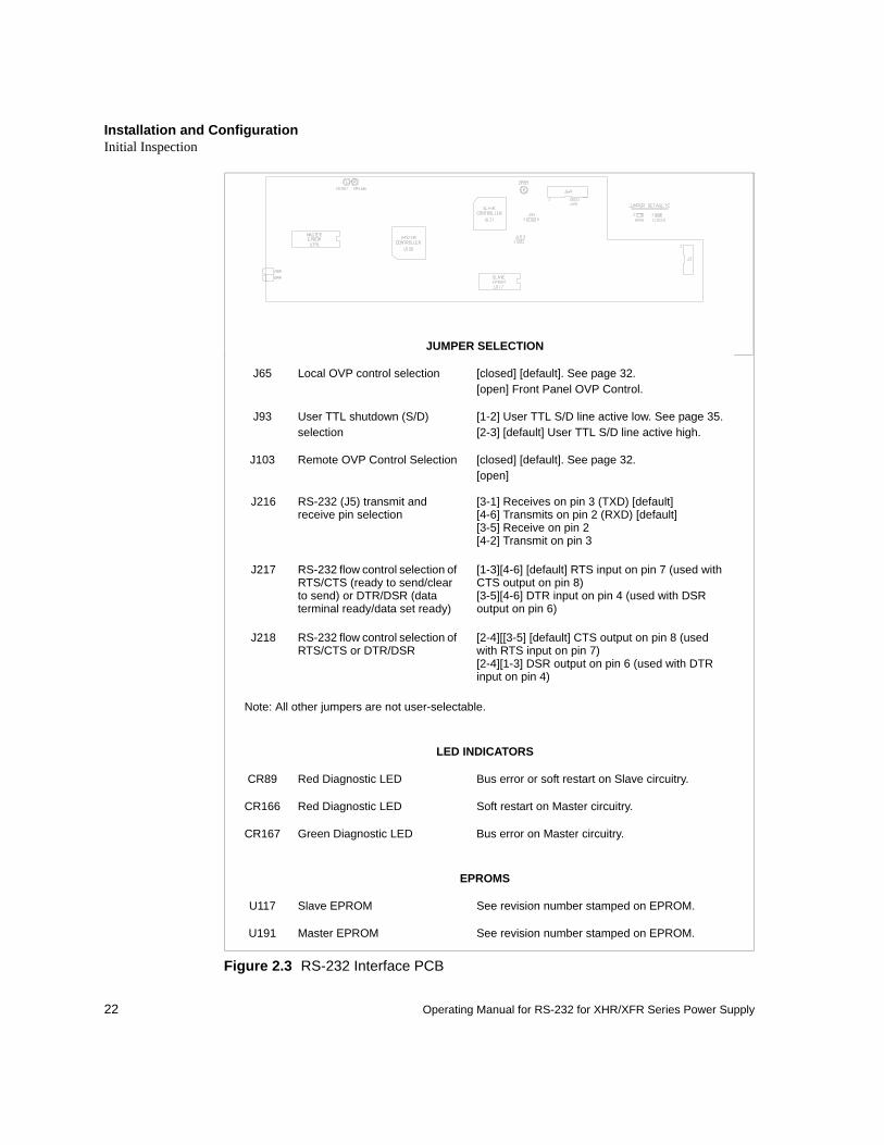
Figure 2.3 RS-232 Interface PCB
JUMPER SELECTION
J65 Local OVP control selection [closed] [default]. See page 32.[open] Front Panel OVP Control.
J93 User TTL shutdown (S/D) selection
[1-2] User TTL S/D line active low. See page 35.[2-3] [default] User TTL S/D line active high.
J103 Remote OVP Control Selection [closed] [default]. See page 32.[open]
J216 RS-232 (J5) transmit and receive pin selection
[3-1] Receives on pin 3 (TXD) [default][4-6] Transmits on pin 2 (RXD) [default][3-5] Receive on pin 2[4-2] Transmit on pin 3
J217 RS-232 flow control selection of RTS/CTS (ready to send/clear to send) or DTR/DSR (data terminal ready/data set ready)
[1-3][4-6] [default] RTS input on pin 7 (used with CTS output on pin 8)[3-5][4-6] DTR input on pin 4 (used with DSR output on pin 6)
J218 RS-232 flow control selection of RTS/CTS or DTR/DSR
[2-4][[3-5] [default] CTS output on pin 8 (used with RTS input on pin 7)[2-4][1-3] DSR output on pin 6 (used with DTR input on pin 4)
Note: All other jumpers are not user-selectable.
LED INDICATORS
CR89 Red Diagnostic LED Bus error or soft restart on Slave circuitry.
CR166 Red Diagnostic LED Soft restart on Master circuitry.
CR167 Green Diagnostic LED Bus error on Master circuitry.
EPROMS
U117 Slave EPROM See revision number stamped on EPROM.
U191 Master EPROM See revision number stamped on EPROM.
Installation and ConfigurationBasic Setup Procedure
23
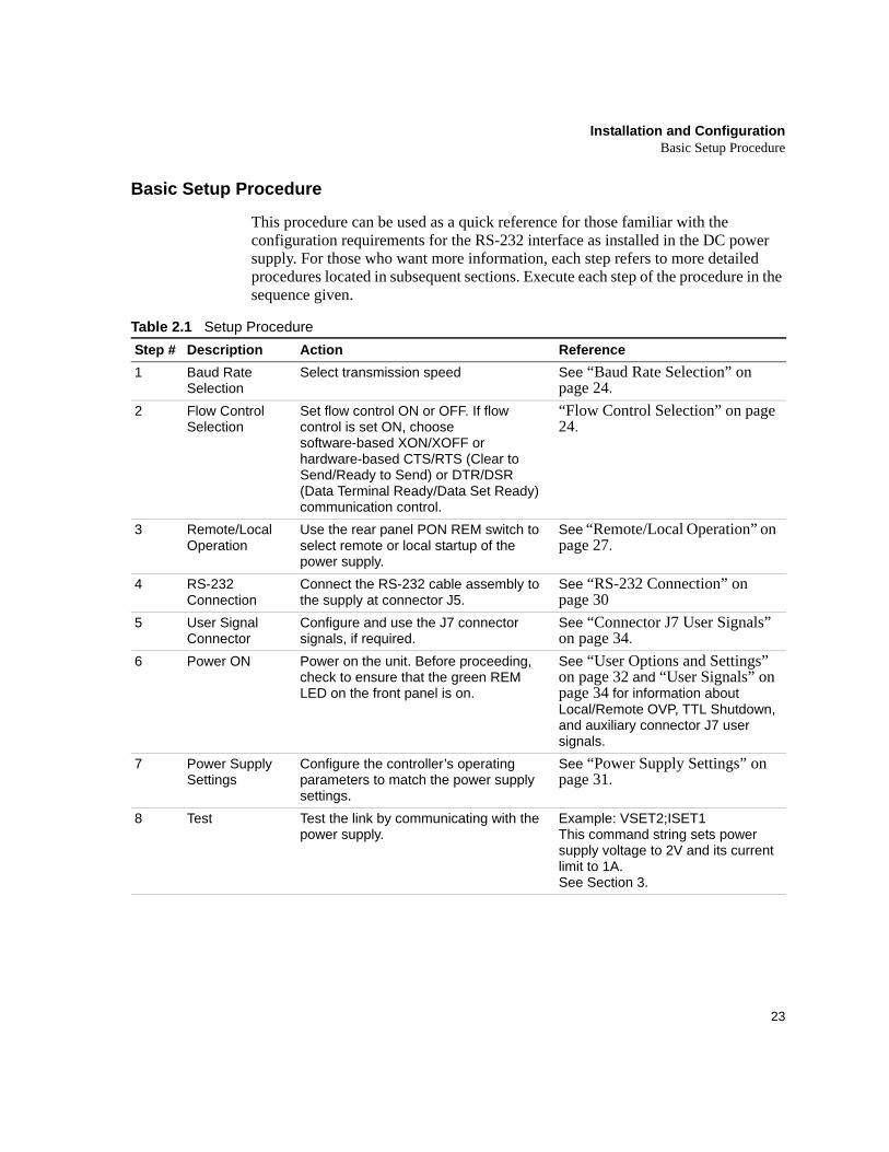
Basic Setup Procedure
This procedure can be used as a quick reference for those familiar with the configuration requirements for the RS-232 interface as installed in the DC power supply. For those who want more information, each step refers to more detailed procedures located in subsequent sections. Execute each step of the procedure in the sequence given.
Table 2.1 Setup ProcedureStep # Description Action Reference1 Baud Rate
SelectionSelect transmission speed See “Baud Rate Selection” on
page 24.2 Flow Control
SelectionSet flow control ON or OFF. If flow control is set ON, choose software-based XON/XOFF or hardware-based CTS/RTS (Clear to Send/Ready to Send) or DTR/DSR (Data Terminal Ready/Data Set Ready) communication control.
“Flow Control Selection” on page 24.
3 Remote/Local Operation
Use the rear panel PON REM switch to select remote or local startup of the power supply.
See “Remote/Local Operation” on page 27.
4 RS-232 Connection
Connect the RS-232 cable assembly to the supply at connector J5.
See “RS-232 Connection” on page 30
5 User Signal Connector
Configure and use the J7 connector signals, if required.
See “Connector J7 User Signals” on page 34.
6 Power ON Power on the unit. Before proceeding, check to ensure that the green REM LED on the front panel is on.
See “User Options and Settings” on page 32 and “User Signals” on page 34 for information about Local/Remote OVP, TTL Shutdown, and auxiliary connector J7 user signals.
7 Power Supply Settings
Configure the controller’s operating parameters to match the power supply settings.
See “Power Supply Settings” on page 31.
8 Test Test the link by communicating with the power supply.
Example: VSET2;ISET1 This command string sets power supply voltage to 2V and its current limit to 1A.See Section 3.
Installation and ConfigurationCommunications
24 Operating Manual for RS-232 for XHR/XFR Series Power Supply
Communications
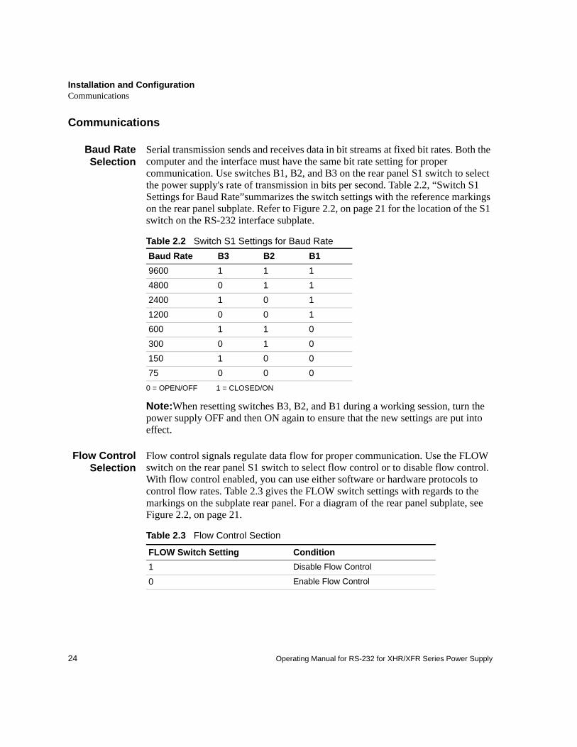
Baud RateSelection
Serial transmission sends and receives data in bit streams at fixed bit rates. Both the computer and the interface must have the same bit rate setting for proper communication. Use switches B1, B2, and B3 on the rear panel S1 switch to select the power supply's rate of transmission in bits per second. Table 2.2, “Switch S1 Settings for Baud Rate”summarizes the switch settings with the reference markings on the rear panel subplate. Refer to Figure 2.2, on page 21 for the location of the S1 switch on the RS-232 interface subplate.
Table 2.2 Switch S1 Settings for Baud Rate
0 = OPEN/OFF 1 = CLOSED/ON
Note:When resetting switches B3, B2, and B1 during a working session, turn the power supply OFF and then ON again to ensure that the new settings are put into effect.
Flow ControlSelection
Flow control signals regulate data flow for proper communication. Use the FLOW switch on the rear panel S1 switch to select flow control or to disable flow control. With flow control enabled, you can use either software or hardware protocols to control flow rates. Table 2.3 gives the FLOW switch settings with regards to the markings on the subplate rear panel. For a diagram of the rear panel subplate, see Figure 2.2, on page 21.
Table 2.3 Flow Control Section
Baud Rate B3 B2 B19600 1 1 14800 0 1 12400 1 0 11200 0 0 1600 1 1 0300 0 1 0150 1 0 075 0 0 0
FLOW Switch Setting Condition1 Disable Flow Control
0 Enable Flow Control
Installation and ConfigurationCommunications
25
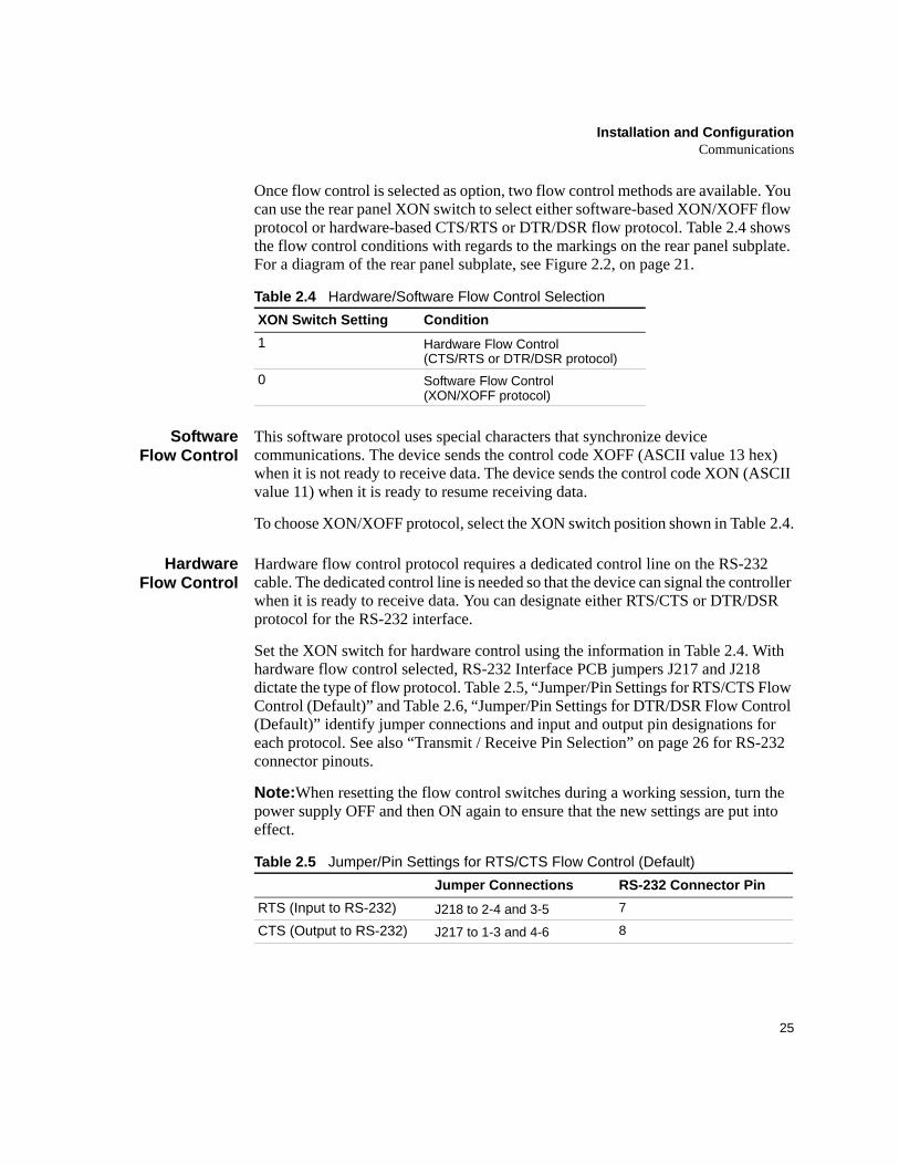
Once flow control is selected as option, two flow control methods are available. You can use the rear panel XON switch to select either software-based XON/XOFF flow protocol or hardware-based CTS/RTS or DTR/DSR flow protocol. Table 2.4 shows the flow control conditions with regards to the markings on the rear panel subplate. For a diagram of the rear panel subplate, see Figure 2.2, on page 21.
Table 2.4 Hardware/Software Flow Control Selection
SoftwareFlow Control
This software protocol uses special characters that synchronize device communications. The device sends the control code XOFF (ASCII value 13 hex) when it is not ready to receive data. The device sends the control code XON (ASCII value 11) when it is ready to resume receiving data.
To choose XON/XOFF protocol, select the XON switch position shown in Table 2.4.
HardwareFlow Control
Hardware flow control protocol requires a dedicated control line on the RS-232 cable. The dedicated control line is needed so that the device can signal the controller when it is ready to receive data. You can designate either RTS/CTS or DTR/DSR protocol for the RS-232 interface.
Set the XON switch for hardware control using the information in Table 2.4. With hardware flow control selected, RS-232 Interface PCB jumpers J217 and J218 dictate the type of flow protocol. Table 2.5, “Jumper/Pin Settings for RTS/CTS Flow Control (Default)” and Table 2.6, “Jumper/Pin Settings for DTR/DSR Flow Control (Default)” identify jumper connections and input and output pin designations for each protocol. See also “Transmit / Receive Pin Selection” on page 26 for RS-232 connector pinouts.
Note:When resetting the flow control switches during a working session, turn the power supply OFF and then ON again to ensure that the new settings are put into effect.
Table 2.5 Jumper/Pin Settings for RTS/CTS Flow Control (Default)
XON Switch Setting Condition1 Hardware Flow Control
(CTS/RTS or DTR/DSR protocol) 0 Software Flow Control
(XON/XOFF protocol)
Jumper Connections RS-232 Connector PinRTS (Input to RS-232) J218 to 2-4 and 3-5 7
CTS (Output to RS-232) J217 to 1-3 and 4-6 8
Installation and ConfigurationCommunications
26 Operating Manual for RS-232 for XHR/XFR Series Power Supply
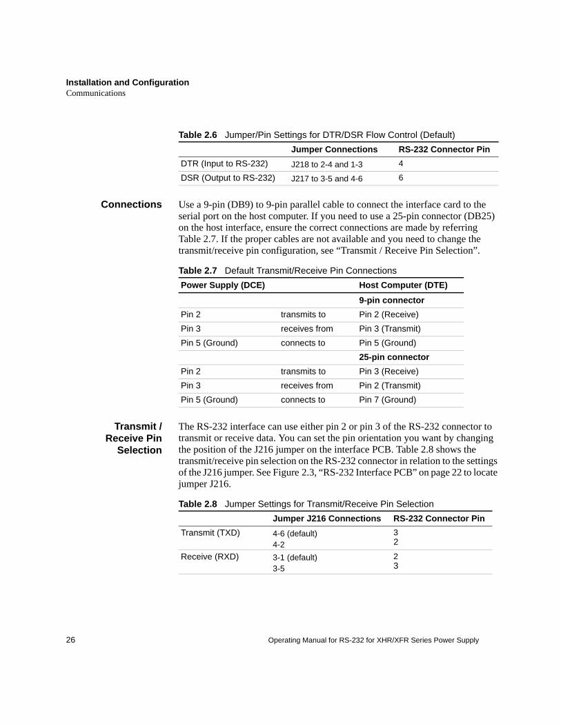
Table 2.6 Jumper/Pin Settings for DTR/DSR Flow Control (Default)
Connections Use a 9-pin (DB9) to 9-pin parallel cable to connect the interface card to the serial port on the host computer. If you need to use a 25-pin connector (DB25) on the host interface, ensure the correct connections are made by referring Table 2.7. If the proper cables are not available and you need to change the transmit/receive pin configuration, see “Transmit / Receive Pin Selection”.
Table 2.7 Default Transmit/Receive Pin Connections
Transmit /Receive Pin
Selection
The RS-232 interface can use either pin 2 or pin 3 of the RS-232 connector to transmit or receive data. You can set the pin orientation you want by changing the position of the J216 jumper on the interface PCB. Table 2.8 shows the transmit/receive pin selection on the RS-232 connector in relation to the settings of the J216 jumper. See Figure 2.3, “RS-232 Interface PCB” on page 22 to locate jumper J216.
Table 2.8 Jumper Settings for Transmit/Receive Pin Selection
Jumper Connections RS-232 Connector PinDTR (Input to RS-232) J218 to 2-4 and 1-3 4
DSR (Output to RS-232) J217 to 3-5 and 4-6 6
Power Supply (DCE) Host Computer (DTE)
9-pin connectorPin 2 transmits to Pin 2 (Receive)Pin 3 receives from Pin 3 (Transmit)Pin 5 (Ground) connects to Pin 5 (Ground)
25-pin connectorPin 2 transmits to Pin 3 (Receive)Pin 3 receives from Pin 2 (Transmit)Pin 5 (Ground) connects to Pin 7 (Ground)
Jumper J216 Connections RS-232 Connector PinTransmit (TXD) 4-6 (default)
4-232
Receive (RXD) 3-1 (default)3-5
23
Installation and ConfigurationRemote/Local Operation
27
Remote/Local Operation
Remote /Local Mode
Startup
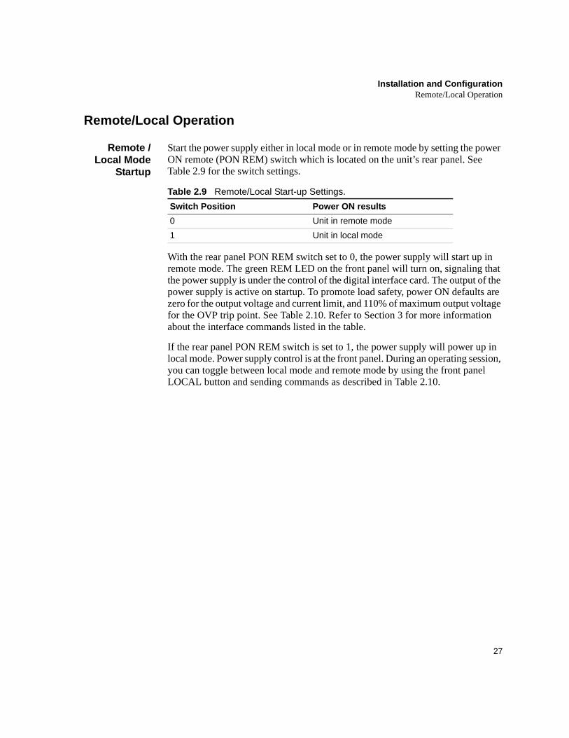
Start the power supply either in local mode or in remote mode by setting the power ON remote (PON REM) switch which is located on the unit’s rear panel. See Table 2.9 for the switch settings.
Table 2.9 Remote/Local Start-up Settings.
With the rear panel PON REM switch set to 0, the power supply will start up in remote mode. The green REM LED on the front panel will turn on, signaling that the power supply is under the control of the digital interface card. The output of the power supply is active on startup. To promote load safety, power ON defaults are zero for the output voltage and current limit, and 110% of maximum output voltage for the OVP trip point. See Table 2.10. Refer to Section 3 for more information about the interface commands listed in the table.
If the rear panel PON REM switch is set to 1, the power supply will power up in local mode. Power supply control is at the front panel. During an operating session, you can toggle between local mode and remote mode by using the front panel LOCAL button and sending commands as described in Table 2.10.
Switch Position Power ON results0 Unit in remote mode1 Unit in local mode
Installation and ConfigurationRemote/Local Operation
28 Operating Manual for RS-232 for XHR/XFR Series Power Supply
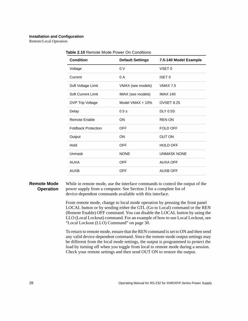
Table 2.10 Remote Mode Power On Conditions
Remote ModeOperation
While in remote mode, use the interface commands to control the output of the power supply from a computer. See Section 3 for a complete list of device-dependent commands available with this interface.
From remote mode, change to local mode operation by pressing the front panel LOCAL button or by sending either the GTL (Go to Local) command or the REN (Remote Enable) OFF command. You can disable the LOCAL button by using the LLO (Local Lockout) command. For an example of how to use Local Lockout, see “Local Lockout (LLO) Command” on page 30.
To return to remote mode, ensure that the REN command is set to ON and then send any valid device-dependent command. Since the remote mode output settings may be different from the local mode settings, the output is programmed to protect the load by turning off when you toggle from local to remote mode during a session. Check your remote settings and then send OUT ON to restore the output.
Condition Default Settings 7.5-140 Model Example
Voltage 0 V VSET 0
Current 0 A ISET 0
Soft Voltage Limit VMAX (see models) VMAX 7.5
Soft Current Limit IMAX (see models) IMAX 140
OVP Trip Voltage Model VMAX + 10% OVSET 8.25
Delay 0.5 s DLY 0.5S
Remote Enable ON REN ON
Foldback Protection OFF FOLD OFF
Output ON OUT ON
Hold OFF HOLD OFF
Unmask NONE UNMASK NONE
AUXA OFF AUXA OFF
AUXB OFF AUXB OFF
Installation and ConfigurationRemote/Local Operation
29
Local ModeOperation
In local mode operation, you set the voltage and current output levels and the OVP trip level with controls located on the front panel. Refer to the operating manual for a description of the functions available at the front panel.
While in local mode operation, you can change power supply control to remote mode by ensuring that REN is ON, then sending any software command and OUT ON to restore the output. Return to local mode by pressing the front panel LOCAL button, unless Local Lockout is in effect. If LLO is in effect, use the GTL command to send the power supply into local mode, or use the REN OFF command to turn off LLO and return the power supply to local mode.
Example:
RemoteEnable (REN)
Command
You can use the Remote Enable command to toggle between local mode and remote mode. The default setting at startup is REN ON. With the remote enable command set at REN ON, you can return the power supply to remote mode whenever you send any command from the computer. Any time that you change from local to remote mode during a session, the output is programmed to turn off, since the remote mode settings may be different from the local mode settings. Send the OUT ON command to restore the output.
You can turn off Remote Enable and move power supply control to the front panel by sending the REN OFF command. If the Local Lockout condition is in effect, sending the REN OFF command will turn off the LLO condition before sending the unit into local mode.
To check whether the power supply is remote enabled, use the REN? query command.
Example:
Press the LOCAL button Set unit to local mode
Id? Put the unit into remote mode(Use any command to do this.)
Press the LOCAL button Return to local mode.
REN ON Enable the power supply to be sent into remote mode
VSET 10;ISET 2 Put the unit into remote operation mode(Use any command to do this.)
Installation and ConfigurationRS-232 Connection
30 Operating Manual for RS-232 for XHR/XFR Series Power Supply
LocalLockout
(LLO)Command
Use the Local Lockout command to disable the LOCAL button on the power supply front panel. With LLO in effect, you cannot return to local control by pressing the front panel LOCAL switch. You can still return to local mode by sending the Go to Local (GTL) command. To turn off LLO and return the power supply to local mode, send the REN OFF command. Only the REN OFF command will remove the LLO condition.
Example:
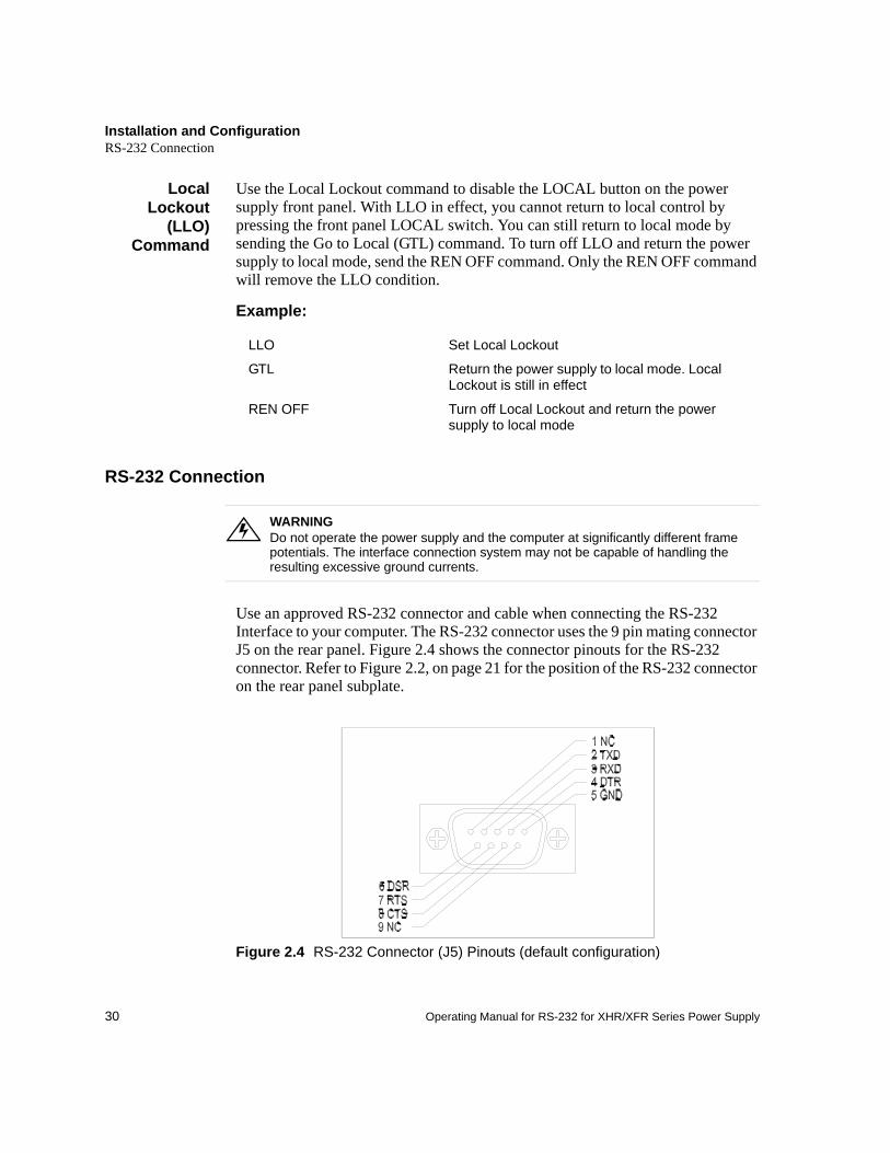
RS-232 Connection
Use an approved RS-232 connector and cable when connecting the RS-232 Interface to your computer. The RS-232 connector uses the 9 pin mating connector J5 on the rear panel. Figure 2.4 shows the connector pinouts for the RS-232 connector. Refer to Figure 2.2, on page 21 for the position of the RS-232 connector on the rear panel subplate.
Figure 2.4 RS-232 Connector (J5) Pinouts (default configuration)
LLO Set Local Lockout
GTL Return the power supply to local mode. Local Lockout is still in effect
REN OFF Turn off Local Lockout and return the power supply to local mode
WARNINGDo not operate the power supply and the computer at significantly different frame potentials. The interface connection system may not be capable of handling the resulting excessive ground currents.
Installation and ConfigurationPower Supply Settings
31
Power Supply Settings
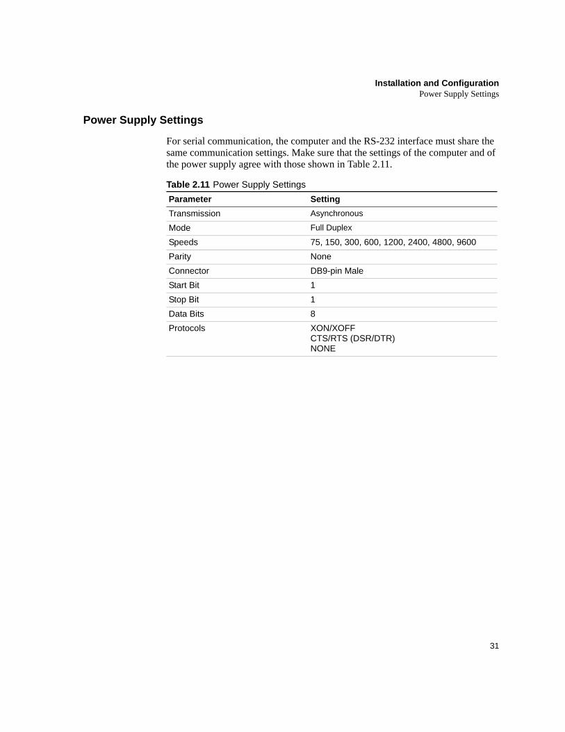
For serial communication, the computer and the RS-232 interface must share the same communication settings. Make sure that the settings of the computer and of the power supply agree with those shown in Table 2.11.
Table 2.11 Power Supply SettingsParameter SettingTransmission Asynchronous
Mode Full Duplex
Speeds 75, 150, 300, 600, 1200, 2400, 4800, 9600Parity NoneConnector DB9-pin MaleStart Bit 1Stop Bit 1Data Bits 8Protocols XON/XOFF
CTS/RTS (DSR/DTR)NONE
Installation and ConfigurationUser Options and Settings
32 Operating Manual for RS-232 for XHR/XFR Series Power Supply
User Options and Settings
You can customize remote operation settings for OVP (over voltage protection) control and TTL shutdown by changing jumper positions on the RS-232 PCB. Refer to the operating manual for information on how to use over voltage protection and TTL shutdown.
OVPSelection
Over voltage protection (OVP) on the RS-232 interface is set at the factory for remote software operation. When operating the power supply in remote mode, you control the OVP trip level using the OVSET software command. If you return the power supply to local operation by using the REN software command or the front panel LOCAL switch, control of the OVP trip level changes from software control to the front panel OVP potentiometer. The default OVP trip level is set as 110% of the power supply's rated output voltage. See Table 2.10, on page 28 for a complete list of remote power ON default settings.
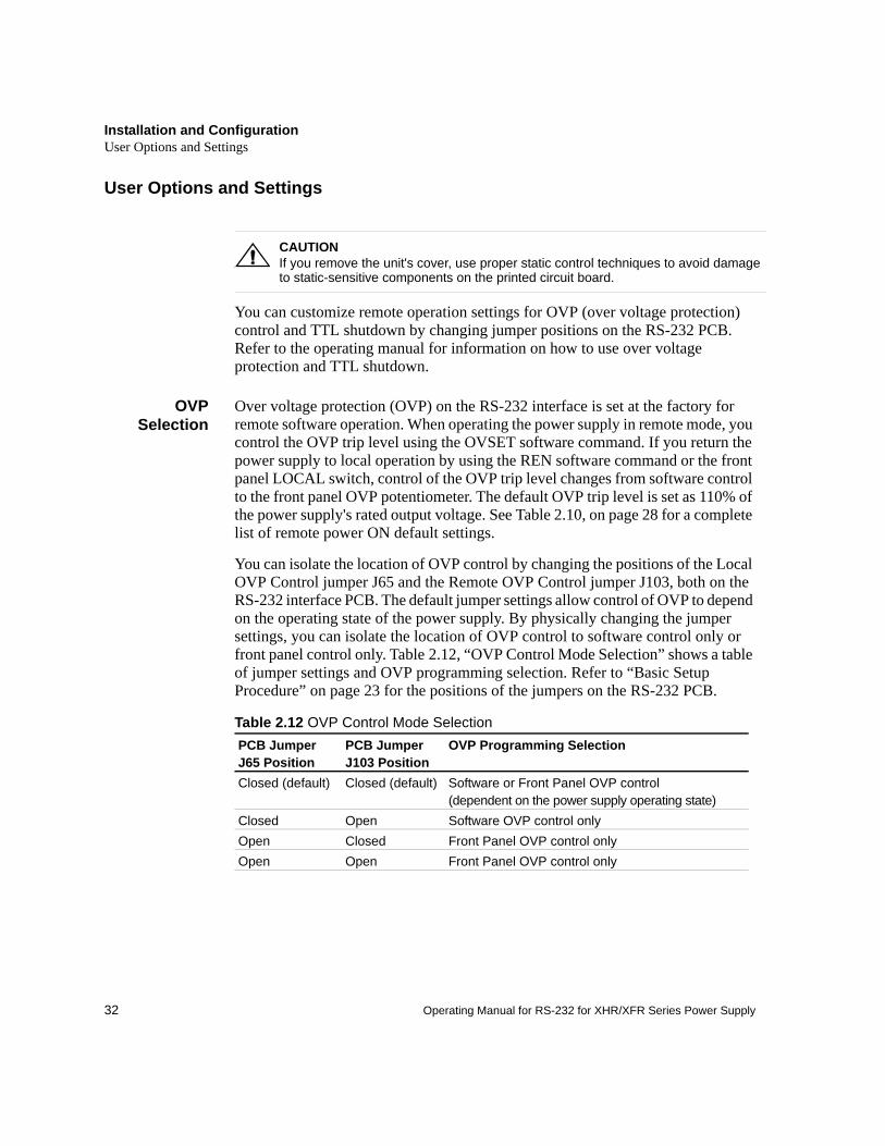
You can isolate the location of OVP control by changing the positions of the Local OVP Control jumper J65 and the Remote OVP Control jumper J103, both on the RS-232 interface PCB. The default jumper settings allow control of OVP to depend on the operating state of the power supply. By physically changing the jumper settings, you can isolate the location of OVP control to software control only or front panel control only. Table 2.12, “OVP Control Mode Selection” shows a table of jumper settings and OVP programming selection. Refer to “Basic Setup Procedure” on page 23 for the positions of the jumpers on the RS-232 PCB.
Table 2.12 OVP Control Mode Selection
!CAUTIONIf you remove the unit's cover, use proper static control techniques to avoid damage to static-sensitive components on the printed circuit board.
PCB Jumper J65 Position
PCB Jumper J103 Position
OVP Programming Selection
Closed (default) Closed (default) Software or Front Panel OVP control (dependent on the power supply operating state)
Closed Open Software OVP control onlyOpen Closed Front Panel OVP control onlyOpen Open Front Panel OVP control only
Installation and ConfigurationUser Options and Settings
33
TTLShutdown
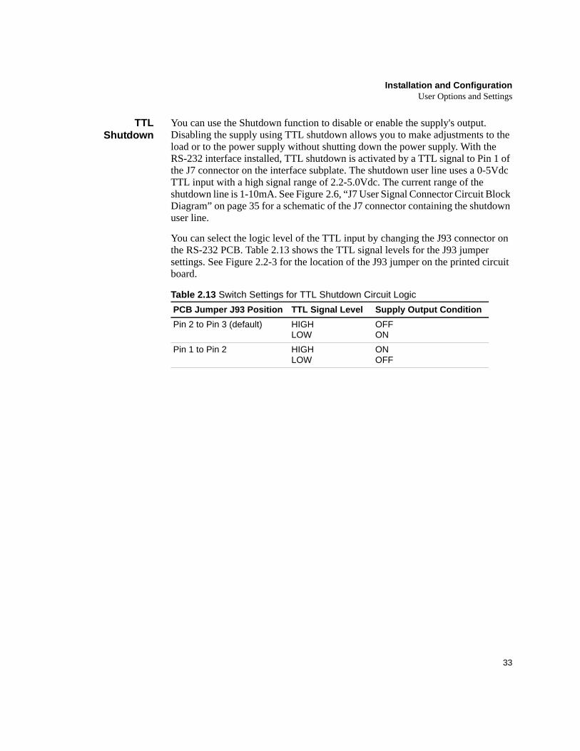
You can use the Shutdown function to disable or enable the supply's output. Disabling the supply using TTL shutdown allows you to make adjustments to the load or to the power supply without shutting down the power supply. With the RS-232 interface installed, TTL shutdown is activated by a TTL signal to Pin 1 of the J7 connector on the interface subplate. The shutdown user line uses a 0-5Vdc TTL input with a high signal range of 2.2-5.0Vdc. The current range of the shutdown line is 1-10mA. See Figure 2.6, “J7 User Signal Connector Circuit Block Diagram” on page 35 for a schematic of the J7 connector containing the shutdown user line.
You can select the logic level of the TTL input by changing the J93 connector on the RS-232 PCB. Table 2.13 shows the TTL signal levels for the J93 jumper settings. See Figure 2.2-3 for the location of the J93 jumper on the printed circuit board.
Table 2.13 Switch Settings for TTL Shutdown Circuit LogicPCB Jumper J93 Position TTL Signal Level Supply Output ConditionPin 2 to Pin 3 (default) HIGH
LOWOFFON
Pin 1 to Pin 2 HIGH LOW
ON OFF
Installation and ConfigurationUser Signals
34 Operating Manual for RS-232 for XHR/XFR Series Power Supply
User Signals
Connector J7User Signals
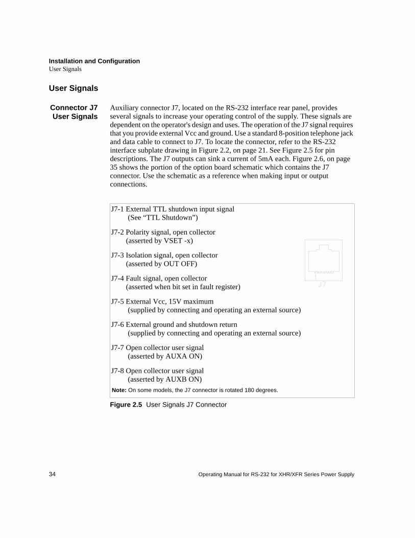
Auxiliary connector J7, located on the RS-232 interface rear panel, provides several signals to increase your operating control of the supply. These signals are dependent on the operator's design and uses. The operation of the J7 signal requires that you provide external Vcc and ground. Use a standard 8-position telephone jack and data cable to connect to J7. To locate the connector, refer to the RS-232 interface subplate drawing in Figure 2.2, on page 21. See Figure 2.5 for pin descriptions. The J7 outputs can sink a current of 5mA each. Figure 2.6, on page 35 shows the portion of the option board schematic which contains the J7 connector. Use the schematic as a reference when making input or output connections.
Figure 2.5 User Signals J7 Connector
J7-1 External TTL shutdown input signal (See “TTL Shutdown”)
J7-2 Polarity signal, open collector (asserted by VSET -x)
J7-3 Isolation signal, open collector (asserted by OUT OFF)
J7-4 Fault signal, open collector (asserted when bit set in fault register)
J7-5 External Vcc, 15V maximum (supplied by connecting and operating an external source)
J7-6 External ground and shutdown return (supplied by connecting and operating an external source)
J7-7 Open collector user signal (asserted by AUXA ON)
J7-8 Open collector user signal (asserted by AUXB ON)
Note: On some models, the J7 connector is rotated 180 degrees.
Installation and ConfigurationUser Signals
35
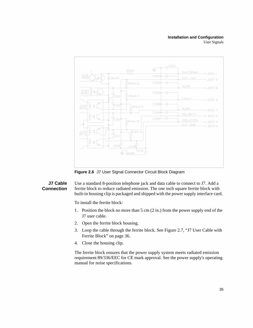
Figure 2.6 J7 User Signal Connector Circuit Block Diagram
J7 CableConnection
Use a standard 8-position telephone jack and data cable to connect to J7. Add a ferrite block to reduce radiated emission. The one inch square ferrite block with built-in housing clip is packaged and shipped with the power supply interface card.
To install the ferrite block:
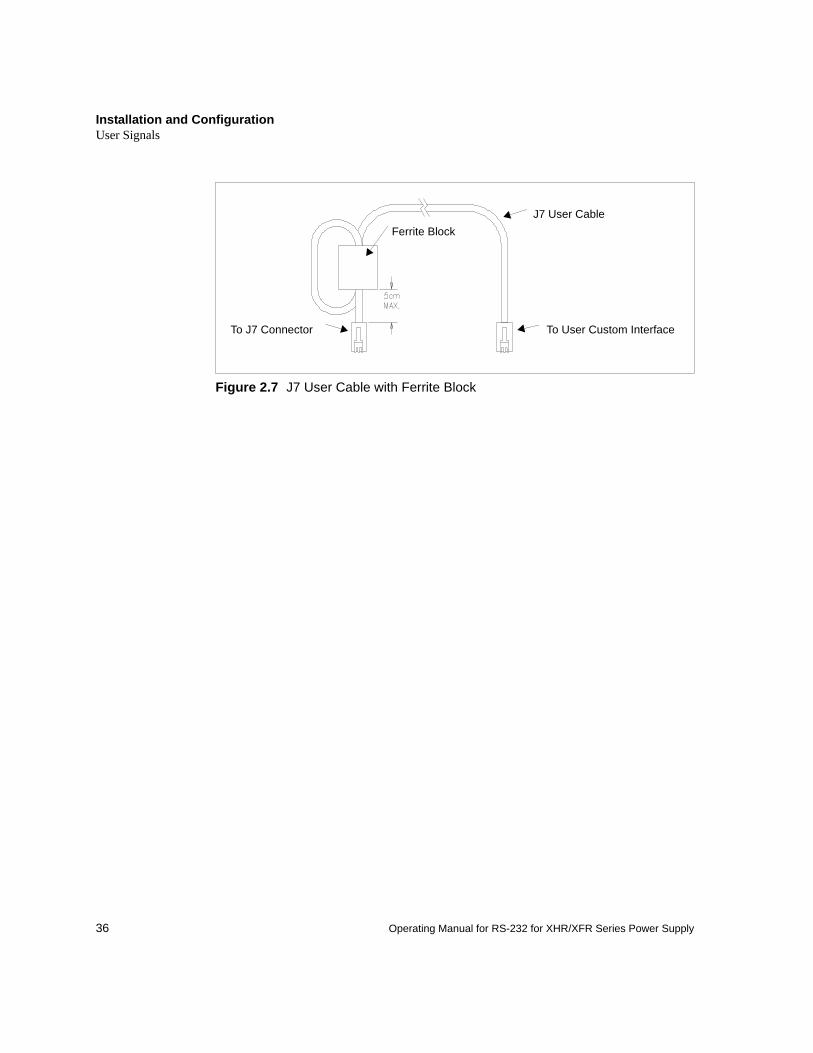
1. Position the block no more than 5 cm (2 in.) from the power supply end of the J7 user cable.
2. Open the ferrite block housing.3. Loop the cable through the ferrite block. See Figure 2.7, “J7 User Cable with
Ferrite Block” on page 36.4. Close the housing clip.
The ferrite block ensures that the power supply system meets radiated emission requirement 89/336/EEC for CE mark approval. See the power supply's operating manual for noise specifications.
Installation and ConfigurationUser Signals
36 Operating Manual for RS-232 for XHR/XFR Series Power Supply
Figure 2.7 J7 User Cable with Ferrite Block
J7 User CableFerrite Block
To User Custom InterfaceTo J7 Connector
37
Section 3. Operation
Introduction
This section covers RS-232 interface programming, including an extensive set of device-dependent commands, and providing error codes, and status and fault register information.
RS-232 Operation
The RS-232 interface card lets you send and receive data between your power supply and computer, relying on bit serial communication. You can use the computer controller to issue commands to the power supply for programming, queries, calibration, or status. The power supply responds to the complete command set of device dependent software commands shown in “Command Reference” on page 44.
Command Syntax
ManualConventions
The manual uses these conventions when displaying command information. These characters are not part of the command but are used to denote parameters used with the command.
< > (angle brackets) Angle brackets enclose a parameter. Do not include the angle brackets in the command line you send to the computer.
/ (slash) Separates two alternative parameters. When a slash separates two parameters, you can use either parameter to achieve the same result. Example: <1/ON>
Entering 1 or ON will achieve the same result.
COMPUTER ENTRY Words typed on the computer are shown in Arial text, full capitals.
OperationCommand Syntax
38 Operating Manual for RS-232 for XHR/XFR Series Power Supply
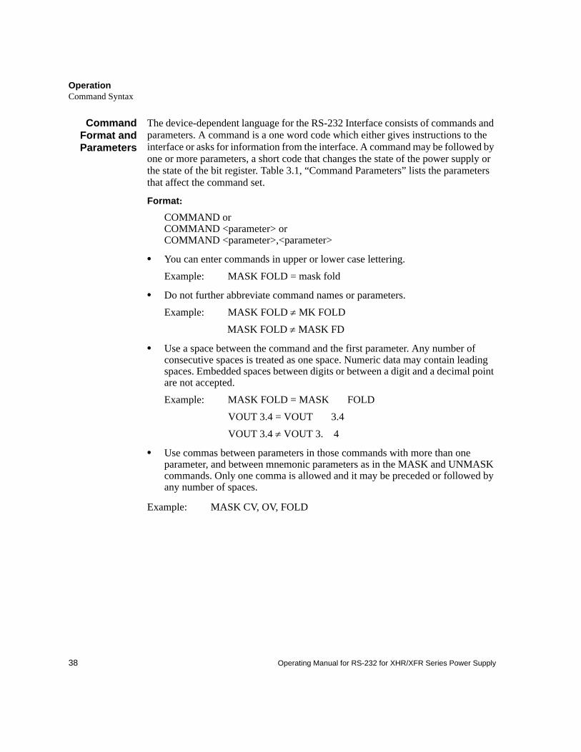
CommandFormat andParameters
The device-dependent language for the RS-232 Interface consists of commands and parameters. A command is a one word code which either gives instructions to the interface or asks for information from the interface. A command may be followed by one or more parameters, a short code that changes the state of the power supply or the state of the bit register. Table 3.1, “Command Parameters” lists the parameters that affect the command set.
Format:
COMMAND or COMMAND <parameter> or COMMAND <parameter>,<parameter>
• You can enter commands in upper or lower case lettering.Example: MASK FOLD = mask fold
• Do not further abbreviate command names or parameters.Example: MASK FOLD ≠ MK FOLD
MASK FOLD ≠ MASK FD
• Use a space between the command and the first parameter. Any number of consecutive spaces is treated as one space. Numeric data may contain leading spaces. Embedded spaces between digits or between a digit and a decimal point are not accepted.Example: MASK FOLD = MASK FOLD
VOUT 3.4 = VOUT 3.4VOUT 3.4 ≠ VOUT 3. 4
• Use commas between parameters in those commands with more than one parameter, and between mnemonic parameters as in the MASK and UNMASK commands. Only one comma is allowed and it may be preceded or followed by any number of spaces.
Example: MASK CV, OV, FOLD
OperationCommand Syntax
39
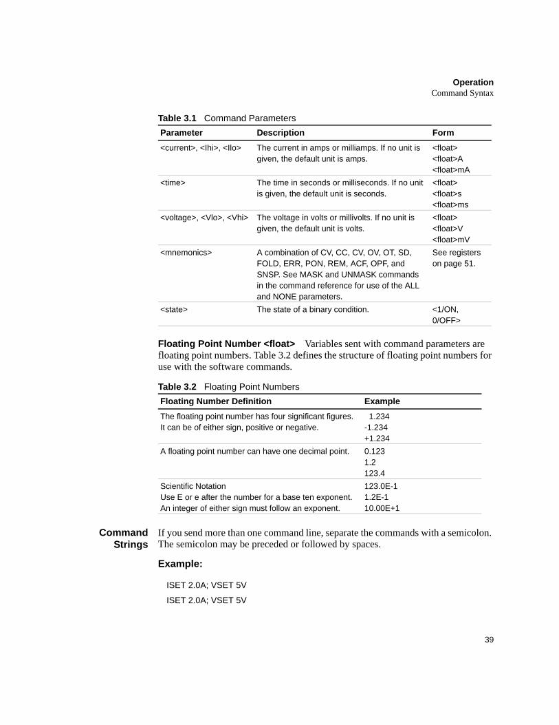
Table 3.1 Command Parameters
Floating Point Number <float> Variables sent with command parameters are floating point numbers. Table 3.2 defines the structure of floating point numbers for use with the software commands.
Table 3.2 Floating Point Numbers
CommandStrings
If you send more than one command line, separate the commands with a semicolon. The semicolon may be preceded or followed by spaces.
Example:
Parameter Description Form<current>, <Ihi>, <Ilo> The current in amps or milliamps. If no unit is
given, the default unit is amps.<float><float>A<float>mA
<time> The time in seconds or milliseconds. If no unit is given, the default unit is seconds.
<float><float>s<float>ms
<voltage>, <Vlo>, <Vhi> The voltage in volts or millivolts. If no unit is given, the default unit is volts.
<float><float>V<float>mV
<mnemonics> A combination of CV, CC, CV, OV, OT, SD, FOLD, ERR, PON, REM, ACF, OPF, and SNSP. See MASK and UNMASK commands in the command reference for use of the ALL and NONE parameters.
See registers on page 51.
<state> The state of a binary condition. <1/ON, 0/OFF>
Floating Number Definition ExampleThe floating point number has four significant figures. It can be of either sign, positive or negative.
1.234-1.234+1.234
A floating point number can have one decimal point. 0.1231.2123.4
Scientific NotationUse E or e after the number for a base ten exponent.An integer of either sign must follow an exponent.
123.0E-11.2E-110.00E+1
ISET 2.0A; VSET 5V
ISET 2.0A; VSET 5V
OperationCommand Syntax
40 Operating Manual for RS-232 for XHR/XFR Series Power Supply
CommandTerminators
Terminators indicate the end of a command string and tell the power supply to execute the command. The termination character is LF (Line Feed).
Format:
COMMAND <parameter>; COMMAND <parameter>, <parameter><LF>
Most computer controllers automatically send LF with output statements.
Order You may send commands in any order, keeping in mind that only those commands received after a HOLD and before a TRG (trigger) will be released by the TRG command. In addition, only these commands received after a supply disable and before a RST (reset) or OUT ON command will be released by the RST command or the OUT command. Commands are executed in the order they are received.
OperationCommand Summary
41
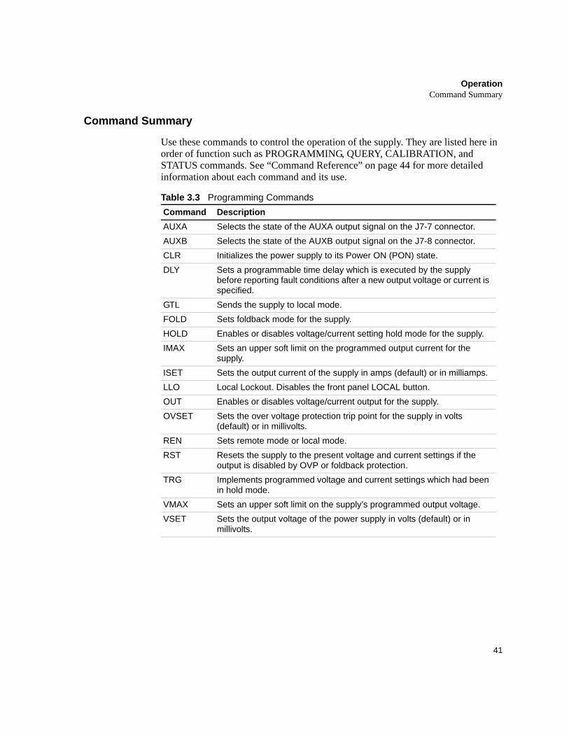
Command Summary
Use these commands to control the operation of the supply. They are listed here in order of function such as PROGRAMMING, QUERY, CALIBRATION, and STATUS commands. See “Command Reference” on page 44 for more detailed information about each command and its use.
Table 3.3 Programming CommandsCommand DescriptionAUXA Selects the state of the AUXA output signal on the J7-7 connector.AUXB Selects the state of the AUXB output signal on the J7-8 connector.CLR Initializes the power supply to its Power ON (PON) state.DLY Sets a programmable time delay which is executed by the supply
before reporting fault conditions after a new output voltage or current is specified.
GTL Sends the supply to local mode.FOLD Sets foldback mode for the supply.HOLD Enables or disables voltage/current setting hold mode for the supply.IMAX Sets an upper soft limit on the programmed output current for the
supply.ISET Sets the output current of the supply in amps (default) or in milliamps.LLO Local Lockout. Disables the front panel LOCAL button.OUT Enables or disables voltage/current output for the supply.OVSET Sets the over voltage protection trip point for the supply in volts
(default) or in millivolts.REN Sets remote mode or local mode.RST Resets the supply to the present voltage and current settings if the
output is disabled by OVP or foldback protection.TRG Implements programmed voltage and current settings which had been
in hold mode.VMAX Sets an upper soft limit on the supply’s programmed output voltage.VSET Sets the output voltage of the power supply in volts (default) or in
millivolts.
OperationCommand Summary
42 Operating Manual for RS-232 for XHR/XFR Series Power Supply
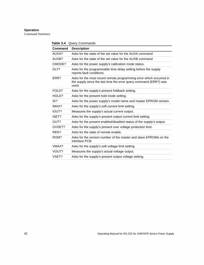
Table 3.4 Query CommandsCommand DescriptionAUXA? Asks for the state of the set value for the AUXA commandAUXB? Asks for the state of the set value for the AUXB commandCMODE? Asks for the power supply’s calibration mode status.DLY? Asks for the programmable time delay setting before the supply
reports fault conditions.ERR? Asks for the most recent remote programming error which occurred in
the supply since the last time the error query command (ERR?) was used.
FOLD? Asks for the supply’s present foldback setting.HOLD? Asks for the present hold mode setting.ID? Asks for the power supply’s model name and master EPROM version.IMAX? Asks for the supply’s soft current limit setting.IOUT? Measures the supply’s actual current output.ISET? Asks for the supply’s present output current limit setting.OUT? Asks for the present enabled/disabled status of the supply’s output.OVSET? Asks for the supply’s present over voltage protection limit.REN? Asks for the state of remote enable.ROM? Asks for the version number of the master and slave EPROMs on the
interface PCB.VMAX? Asks for the supply’s soft voltage limit setting.VOUT? Measures the supply’s actual voltage output.VSET? Asks for the supply’s present output voltage setting.
OperationCommand Summary
43
Table 3.5 Calibration Commands
Table 3.6 Status Commands
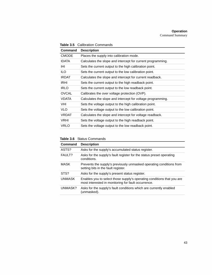
Command DescriptionCMODE Places the supply into calibration mode.IDATA Calculates the slope and intercept for current programming.IHI Sets the current output to the high calibration point.ILO Sets the current output to the low calibration point.IRDAT Calculates the slope and intercept for current readback.IRHI Sets the current output to the high readback point.IRLO Sets the current output to the low readback point.OVCAL Calibrates the over voltage protection (OVP).VDATA Calculates the slope and intercept for voltage programming.VHI Sets the voltage output to the high calibration point.VLO Sets the voltage output to the low calibration point.VRDAT Calculates the slope and intercept for voltage readback.VRHI Sets the voltage output to the high readback point.VRLO Sets the voltage output to the low readback point.
Command DescriptionASTS? Asks for the supply’s accumulated status register.FAULT? Asks for the supply’s fault register for the status preset operating
conditions.MASK Prevents the supply's previously unmasked operating conditions from
setting bits in the fault register.STS? Asks for the supply’s present status register.UNMASK Enables you to select those supply's operating conditions that you are
most interested in monitoring for fault occurrence.UNMASK? Asks for the supply's fault conditions which are currently enabled
(unmasked).
OperationCommand Reference
44 Operating Manual for RS-232 for XHR/XFR Series Power Supply
Command Reference
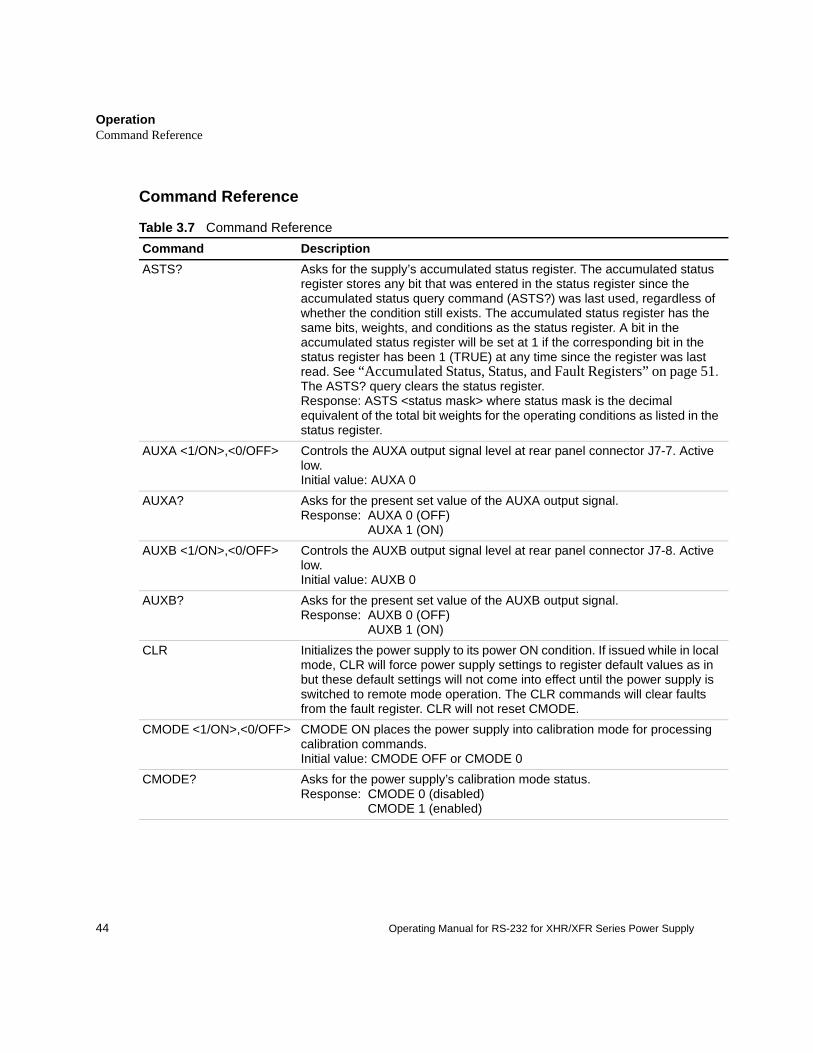
Table 3.7 Command ReferenceCommand DescriptionASTS? Asks for the supply’s accumulated status register. The accumulated status
register stores any bit that was entered in the status register since the accumulated status query command (ASTS?) was last used, regardless of whether the condition still exists. The accumulated status register has the same bits, weights, and conditions as the status register. A bit in the accumulated status register will be set at 1 if the corresponding bit in the status register has been 1 (TRUE) at any time since the register was last read. See “Accumulated Status, Status, and Fault Registers” on page 51. The ASTS? query clears the status register.Response: ASTS <status mask> where status mask is the decimal equivalent of the total bit weights for the operating conditions as listed in the status register.
AUXA <1/ON>,<0/OFF> Controls the AUXA output signal level at rear panel connector J7-7. Active low.Initial value: AUXA 0
AUXA? Asks for the present set value of the AUXA output signal.Response: AUXA 0 (OFF)
AUXA 1 (ON)AUXB <1/ON>,<0/OFF> Controls the AUXB output signal level at rear panel connector J7-8. Active
low.Initial value: AUXB 0
AUXB? Asks for the present set value of the AUXB output signal.Response: AUXB 0 (OFF)
AUXB 1 (ON)CLR Initializes the power supply to its power ON condition. If issued while in local
mode, CLR will force power supply settings to register default values as in but these default settings will not come into effect until the power supply is switched to remote mode operation. The CLR commands will clear faults from the fault register. CLR will not reset CMODE.
CMODE <1/ON>,<0/OFF> CMODE ON places the power supply into calibration mode for processing calibration commands.Initial value: CMODE OFF or CMODE 0
CMODE? Asks for the power supply’s calibration mode status.Response: CMODE 0 (disabled)
CMODE 1 (enabled)
OperationCommand Reference
45
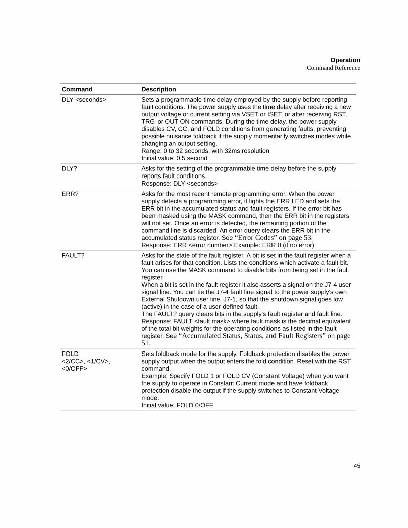
Command DescriptionDLY <seconds> Sets a programmable time delay employed by the supply before reporting
fault conditions. The power supply uses the time delay after receiving a new output voltage or current setting via VSET or ISET, or after receiving RST, TRG, or OUT ON commands. During the time delay, the power supply disables CV, CC, and FOLD conditions from generating faults, preventing possible nuisance foldback if the supply momentarily switches modes while changing an output setting.Range: 0 to 32 seconds, with 32ms resolutionInitial value: 0.5 second
DLY? Asks for the setting of the programmable time delay before the supply reports fault conditions.Response: DLY <seconds>
ERR? Asks for the most recent remote programming error. When the power supply detects a programming error, it lights the ERR LED and sets the ERR bit in the accumulated status and fault registers. If the error bit has been masked using the MASK command, then the ERR bit in the registers will not set. Once an error is detected, the remaining portion of the command line is discarded. An error query clears the ERR bit in the accumulated status register. See “Error Codes” on page 53.Response: ERR <error number> Example: ERR 0 (if no error)
FAULT? Asks for the state of the fault register. A bit is set in the fault register when a fault arises for that condition. Lists the conditions which activate a fault bit. You can use the MASK command to disable bits from being set in the fault register. When a bit is set in the fault register it also asserts a signal on the J7-4 user signal line. You can tie the J7-4 fault line signal to the power supply's own External Shutdown user line, J7-1, so that the shutdown signal goes low (active) in the case of a user-defined fault.The FAULT? query clears bits in the supply's fault register and fault line.Response: FAULT <fault mask> where fault mask is the decimal equivalent of the total bit weights for the operating conditions as listed in the fault register. See “Accumulated Status, Status, and Fault Registers” on page 51.
FOLD<2/CC>, <1/CV>, <0/OFF>
Sets foldback mode for the supply. Foldback protection disables the power supply output when the output enters the fold condition. Reset with the RST command.Example: Specify FOLD 1 or FOLD CV (Constant Voltage) when you want the supply to operate in Constant Current mode and have foldback protection disable the output if the supply switches to Constant Voltage mode. Initial value: FOLD 0/OFF
OperationCommand Reference
46 Operating Manual for RS-232 for XHR/XFR Series Power Supply
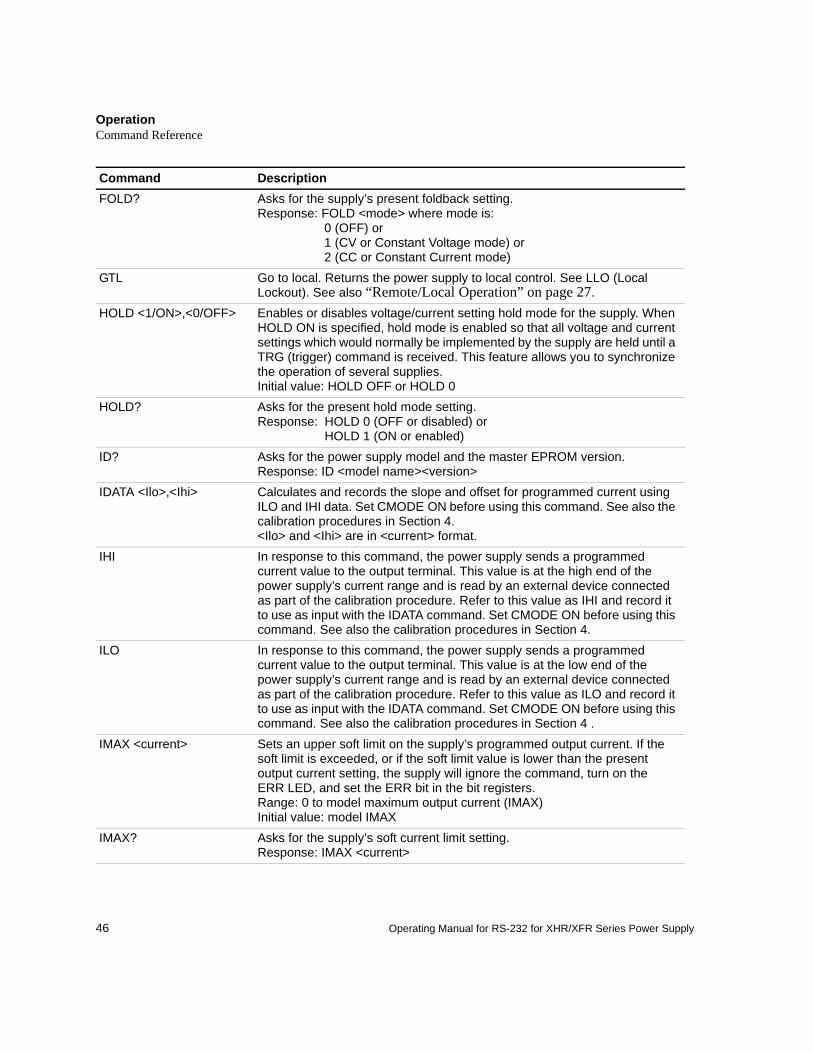
Command DescriptionFOLD? Asks for the supply’s present foldback setting.
Response: FOLD <mode> where mode is: 0 (OFF) or1 (CV or Constant Voltage mode) or2 (CC or Constant Current mode)
GTL Go to local. Returns the power supply to local control. See LLO (Local Lockout). See also “Remote/Local Operation” on page 27.
HOLD <1/ON>,<0/OFF> Enables or disables voltage/current setting hold mode for the supply. When HOLD ON is specified, hold mode is enabled so that all voltage and current settings which would normally be implemented by the supply are held until a TRG (trigger) command is received. This feature allows you to synchronize the operation of several supplies.Initial value: HOLD OFF or HOLD 0
HOLD? Asks for the present hold mode setting.Response: HOLD 0 (OFF or disabled) or
HOLD 1 (ON or enabled)ID? Asks for the power supply model and the master EPROM version.
Response: ID <model name><version>IDATA <Ilo>,<Ihi> Calculates and records the slope and offset for programmed current using
ILO and IHI data. Set CMODE ON before using this command. See also the calibration procedures in Section 4.<Ilo> and <Ihi> are in <current> format.
IHI In response to this command, the power supply sends a programmed current value to the output terminal. This value is at the high end of the power supply’s current range and is read by an external device connected as part of the calibration procedure. Refer to this value as IHI and record it to use as input with the IDATA command. Set CMODE ON before using this command. See also the calibration procedures in Section 4.
ILO In response to this command, the power supply sends a programmed current value to the output terminal. This value is at the low end of the power supply’s current range and is read by an external device connected as part of the calibration procedure. Refer to this value as ILO and record it to use as input with the IDATA command. Set CMODE ON before using this command. See also the calibration procedures in Section 4 .
IMAX <current> Sets an upper soft limit on the supply’s programmed output current. If the soft limit is exceeded, or if the soft limit value is lower than the present output current setting, the supply will ignore the command, turn on the ERR LED, and set the ERR bit in the bit registers.Range: 0 to model maximum output current (IMAX)Initial value: model IMAX
IMAX? Asks for the supply’s soft current limit setting.Response: IMAX <current>
OperationCommand Reference
47
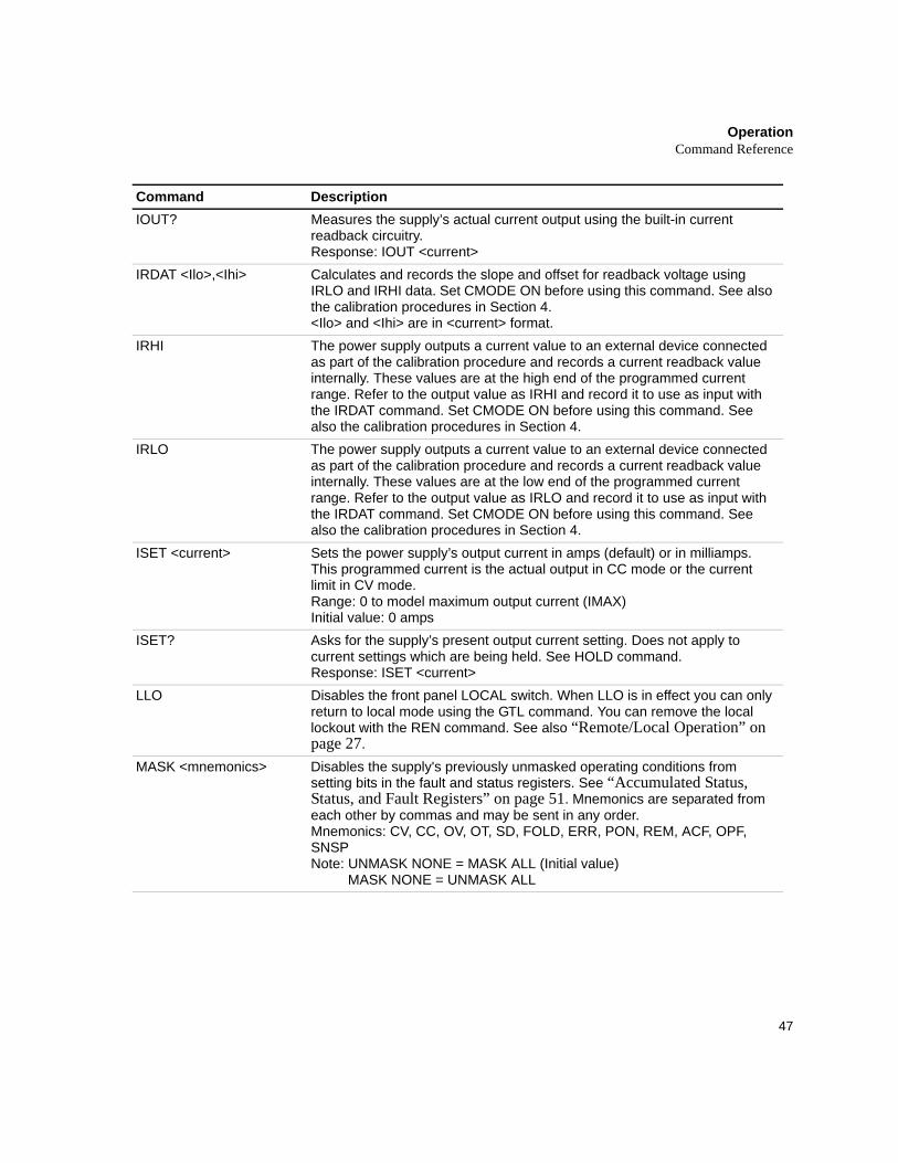
Command DescriptionIOUT? Measures the supply’s actual current output using the built-in current
readback circuitry.Response: IOUT <current>
IRDAT <Ilo>,<Ihi> Calculates and records the slope and offset for readback voltage using IRLO and IRHI data. Set CMODE ON before using this command. See also the calibration procedures in Section 4.<Ilo> and <Ihi> are in <current> format.
IRHI The power supply outputs a current value to an external device connected as part of the calibration procedure and records a current readback value internally. These values are at the high end of the programmed current range. Refer to the output value as IRHI and record it to use as input with the IRDAT command. Set CMODE ON before using this command. See also the calibration procedures in Section 4.
IRLO The power supply outputs a current value to an external device connected as part of the calibration procedure and records a current readback value internally. These values are at the low end of the programmed current range. Refer to the output value as IRLO and record it to use as input with the IRDAT command. Set CMODE ON before using this command. See also the calibration procedures in Section 4.
ISET <current> Sets the power supply’s output current in amps (default) or in milliamps. This programmed current is the actual output in CC mode or the current limit in CV mode.Range: 0 to model maximum output current (IMAX)Initial value: 0 amps
ISET? Asks for the supply’s present output current setting. Does not apply to current settings which are being held. See HOLD command.Response: ISET <current>
LLO Disables the front panel LOCAL switch. When LLO is in effect you can only return to local mode using the GTL command. You can remove the local lockout with the REN command. See also “Remote/Local Operation” on page 27.
MASK <mnemonics> Disables the supply's previously unmasked operating conditions from setting bits in the fault and status registers. See “Accumulated Status, Status, and Fault Registers” on page 51. Mnemonics are separated from each other by commas and may be sent in any order.Mnemonics: CV, CC, OV, OT, SD, FOLD, ERR, PON, REM, ACF, OPF, SNSPNote: UNMASK NONE = MASK ALL (Initial value)
MASK NONE = UNMASK ALL
OperationCommand Reference
48 Operating Manual for RS-232 for XHR/XFR Series Power Supply
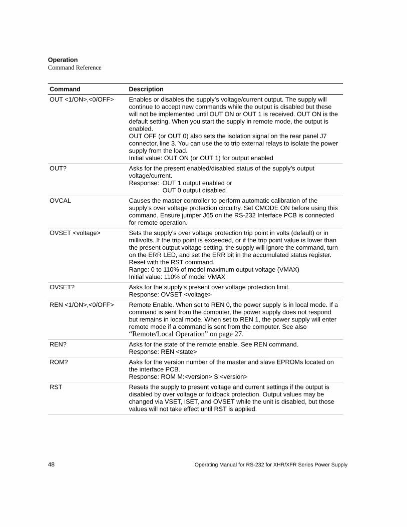
Command DescriptionOUT <1/ON>,<0/OFF> Enables or disables the supply’s voltage/current output. The supply will
continue to accept new commands while the output is disabled but these will not be implemented until OUT ON or OUT 1 is received. OUT ON is the default setting. When you start the supply in remote mode, the output is enabled.OUT OFF (or OUT 0) also sets the isolation signal on the rear panel J7 connector, line 3. You can use the to trip external relays to isolate the power supply from the load.Initial value: OUT ON (or OUT 1) for output enabled
OUT? Asks for the present enabled/disabled status of the supply’s output voltage/current.Response: OUT 1 output enabled or
OUT 0 output disabledOVCAL Causes the master controller to perform automatic calibration of the
supply’s over voltage protection circuitry. Set CMODE ON before using this command. Ensure jumper J65 on the RS-232 Interface PCB is connected for remote operation.
OVSET <voltage> Sets the supply’s over voltage protection trip point in volts (default) or in millivolts. If the trip point is exceeded, or if the trip point value is lower than the present output voltage setting, the supply will ignore the command, turn on the ERR LED, and set the ERR bit in the accumulated status register. Reset with the RST command.Range: 0 to 110% of model maximum output voltage (VMAX)Initial value: 110% of model VMAX
OVSET? Asks for the supply’s present over voltage protection limit.Response: OVSET <voltage>
REN <1/ON>,<0/OFF> Remote Enable. When set to REN 0, the power supply is in local mode. If a command is sent from the computer, the power supply does not respond but remains in local mode. When set to REN 1, the power supply will enter remote mode if a command is sent from the computer. See also “Remote/Local Operation” on page 27.
REN? Asks for the state of the remote enable. See REN command.Response: REN <state>
ROM? Asks for the version number of the master and slave EPROMs located on the interface PCB.Response: ROM M:<version> S:<version>
RST Resets the supply to present voltage and current settings if the output is disabled by over voltage or foldback protection. Output values may be changed via VSET, ISET, and OVSET while the unit is disabled, but those values will not take effect until RST is applied.
OperationCommand Reference
49
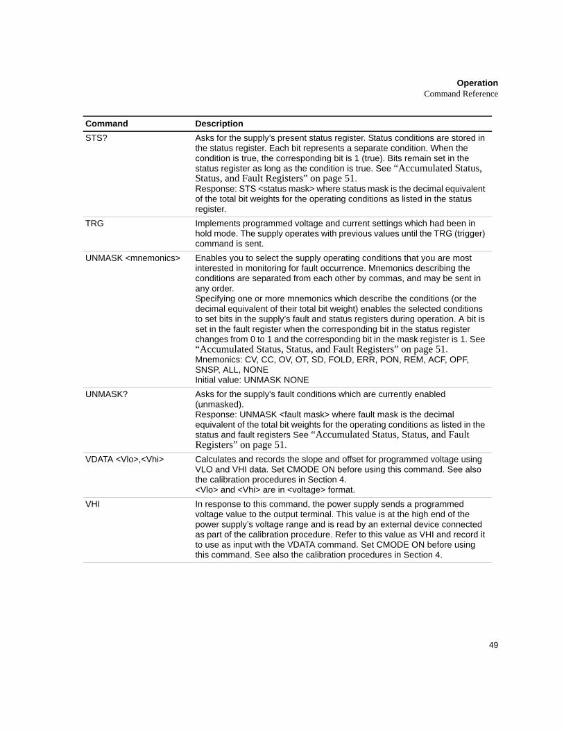
Command DescriptionSTS? Asks for the supply’s present status register. Status conditions are stored in
the status register. Each bit represents a separate condition. When the condition is true, the corresponding bit is 1 (true). Bits remain set in the status register as long as the condition is true. See “Accumulated Status, Status, and Fault Registers” on page 51.Response: STS <status mask> where status mask is the decimal equivalent of the total bit weights for the operating conditions as listed in the status register.
TRG Implements programmed voltage and current settings which had been in hold mode. The supply operates with previous values until the TRG (trigger) command is sent.
UNMASK <mnemonics> Enables you to select the supply operating conditions that you are most interested in monitoring for fault occurrence. Mnemonics describing the conditions are separated from each other by commas, and may be sent in any order.Specifying one or more mnemonics which describe the conditions (or the decimal equivalent of their total bit weight) enables the selected conditions to set bits in the supply’s fault and status registers during operation. A bit is set in the fault register when the corresponding bit in the status register changes from 0 to 1 and the corresponding bit in the mask register is 1. See “Accumulated Status, Status, and Fault Registers” on page 51.Mnemonics: CV, CC, OV, OT, SD, FOLD, ERR, PON, REM, ACF, OPF, SNSP, ALL, NONEInitial value: UNMASK NONE
UNMASK? Asks for the supply's fault conditions which are currently enabled (unmasked).Response: UNMASK <fault mask> where fault mask is the decimal equivalent of the total bit weights for the operating conditions as listed in the status and fault registers See “Accumulated Status, Status, and Fault Registers” on page 51.
VDATA <Vlo>,<Vhi> Calculates and records the slope and offset for programmed voltage using VLO and VHI data. Set CMODE ON before using this command. See also the calibration procedures in Section 4.<Vlo> and <Vhi> are in <voltage> format.
VHI In response to this command, the power supply sends a programmed voltage value to the output terminal. This value is at the high end of the power supply’s voltage range and is read by an external device connected as part of the calibration procedure. Refer to this value as VHI and record it to use as input with the VDATA command. Set CMODE ON before using this command. See also the calibration procedures in Section 4.
OperationCommand Reference
50 Operating Manual for RS-232 for XHR/XFR Series Power Supply
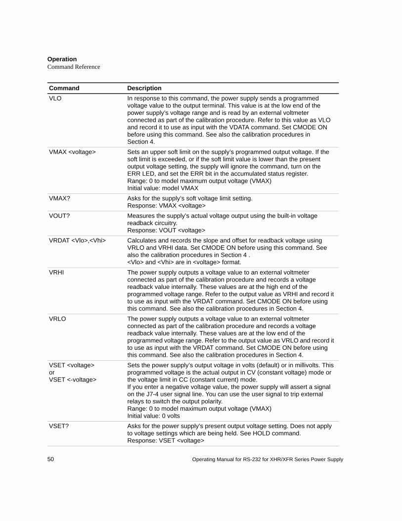
Command DescriptionVLO In response to this command, the power supply sends a programmed
voltage value to the output terminal. This value is at the low end of the power supply’s voltage range and is read by an external voltmeter connected as part of the calibration procedure. Refer to this value as VLO and record it to use as input with the VDATA command. Set CMODE ON before using this command. See also the calibration procedures in Section 4.
VMAX <voltage> Sets an upper soft limit on the supply’s programmed output voltage. If the soft limit is exceeded, or if the soft limit value is lower than the present output voltage setting, the supply will ignore the command, turn on the ERR LED, and set the ERR bit in the accumulated status register.Range: 0 to model maximum output voltage (VMAX)Initial value: model VMAX
VMAX? Asks for the supply’s soft voltage limit setting.Response: VMAX <voltage>
VOUT? Measures the supply’s actual voltage output using the built-in voltage readback circuitry.Response: VOUT <voltage>
VRDAT <Vlo>,<Vhi> Calculates and records the slope and offset for readback voltage using VRLO and VRHI data. Set CMODE ON before using this command. See also the calibration procedures in Section 4 .<Vlo> and <Vhi> are in <voltage> format.
VRHI The power supply outputs a voltage value to an external voltmeter connected as part of the calibration procedure and records a voltage readback value internally. These values are at the high end of the programmed voltage range. Refer to the output value as VRHI and record it to use as input with the VRDAT command. Set CMODE ON before using this command. See also the calibration procedures in Section 4.
VRLO The power supply outputs a voltage value to an external voltmeter connected as part of the calibration procedure and records a voltage readback value internally. These values are at the low end of the programmed voltage range. Refer to the output value as VRLO and record it to use as input with the VRDAT command. Set CMODE ON before using this command. See also the calibration procedures in Section 4.
VSET <voltage>orVSET <-voltage>
Sets the power supply’s output voltage in volts (default) or in millivolts. This programmed voltage is the actual output in CV (constant voltage) mode or the voltage limit in CC (constant current) mode. If you enter a negative voltage value, the power supply will assert a signal on the J7-4 user signal line. You can use the user signal to trip external relays to switch the output polarity. Range: 0 to model maximum output voltage (VMAX)Initial value: 0 volts
VSET? Asks for the power supply’s present output voltage setting. Does not apply to voltage settings which are being held. See HOLD command.Response: VSET <voltage>
OperationAccumulated Status, Status, and Fault Registers
51
Accumulated Status, Status, and Fault Registers
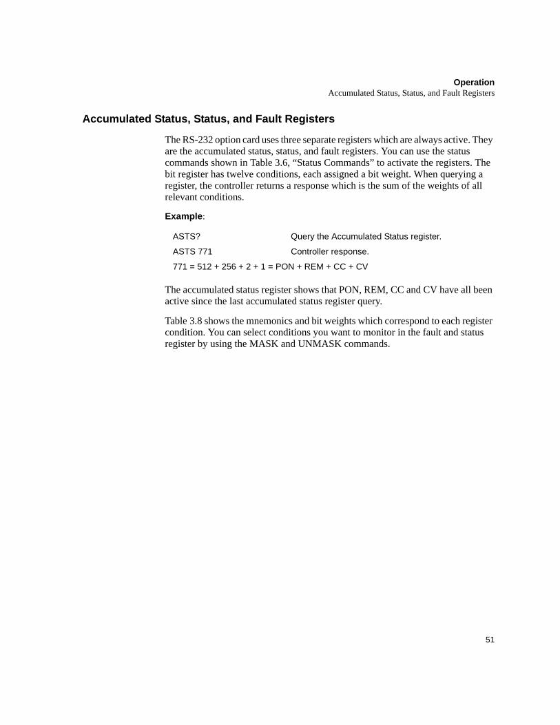
The RS-232 option card uses three separate registers which are always active. They are the accumulated status, status, and fault registers. You can use the status commands shown in Table 3.6, “Status Commands” to activate the registers. The bit register has twelve conditions, each assigned a bit weight. When querying a register, the controller returns a response which is the sum of the weights of all relevant conditions.
Example:
The accumulated status register shows that PON, REM, CC and CV have all been active since the last accumulated status register query.
Table 3.8 shows the mnemonics and bit weights which correspond to each register condition. You can select conditions you want to monitor in the fault and status register by using the MASK and UNMASK commands.
ASTS? Query the Accumulated Status register.
ASTS 771 Controller response.
771 = 512 + 256 + 2 + 1 = PON + REM + CC + CV
OperationAccumulated Status, Status, and Fault Registers
52 Operating Manual for RS-232 for XHR/XFR Series Power Supply
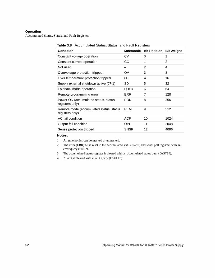
Table 3.8 Accumulated Status, Status, and Fault Registers
Notes:1. All mnemonics can be masked or unmasked.2. The error (ERR) bit is reset in the accumulated status, status, and serial poll registers with an
error query (ERR?).3. The accumulated status register is cleared with an accumulated status query (ASTS?).4. A fault is cleared with a fault query (FAULT?).
Condition Mnemonic Bit Position Bit WeightConstant voltage operation CV 0 1Constant current operation CC 1 2Not used – 2 4Overvoltage protection tripped OV 3 8Over temperature protection tripped OT 4 16Supply external shutdown active (J7-1) SD 5 32Foldback mode operation FOLD 6 64Remote programming error ERR 7 128Power ON (accumulated status, status registers only)
PON 8 256
Remote mode (accumulated status, status registers only)
REM 9 512
AC fail condition ACF 10 1024Output fail condition OPF 11 2048Sense protection tripped SNSP 12 4096
OperationError Codes
53
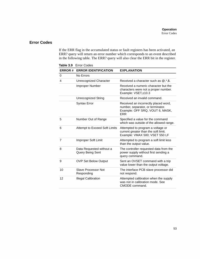
Error Codes
If the ERR flag in the accumulated status or fault registers has been activated, an ERR? query will return an error number which corresponds to an event described in the following table. The ERR? query will also clear the ERR bit in the register.
Table 3.9 Error CodesERROR # ERROR IDENTIFICATION EXPLANATION0 No Errors
4 Unrecognized Character Received a character such as @,*,$.Improper Number Received a numeric character but the
characters were not a proper number.Example: VSET,±10.3
Unrecognized String Received an invalid command.
Syntax Error Received an incorrectly placed word, number, separator, or terminator.Example: OFF SRQ, VOUT 6, MASK, ERR
5 Number Out of Range Specified a value for the command which was outside of the allowed range.
6 Attempt to Exceed Soft Limits Attempted to program a voltage or current greater than the soft limit.Example: VMAX 500; VSET 550 LF
7 Improper Soft Limit Attempted to program a soft limit less than the output value.
8 Data Requested without a Query Being Sent
The controller requested data from the power supply without first sending a query command.
9 OVP Set Below Output Sent an OVSET command with a trip value lower than the output voltage.
10 Slave Processor Not Responding
The interface PCB slave processor did not respond.
12 Illegal Calibration Attempted calibration when the supply was not in calibration mode. See CMODE command.
OperationTroubleshooting
54 Operating Manual for RS-232 for XHR/XFR Series Power Supply
Troubleshooting
DiagnosticLEDs
This section describes the diagnostic LEDs found on the RS-232 interface.
Computer Operating Properly (COP) LEDs The RS-232 interface provides three diagnostic LEDs, located at CR167, CR166, and CR89 on its PCB. Refer to Figure 2.3, ‘RS-232 Interface PCB” on page 22, for their locations. At present, these LEDs turn on to signal COP events for the interface's microprocessors. Issue a RST (reset) command to turn off the diagnostic LEDs.
The green COP LED at circuit designation CR167 indicates that the RS-232 interface microprocessor successfully recovered from a timeout error due to a communications bus error. The event is transparent to the RS-232 communications line continues to function normally.
The red COP LED at CR166 indicates that a transparent restart caused by noise in the master processor circuitry has occurred.
The red COP LED at CR89 indicates that a transparent restart caused by noise in the slave processor circuitry has occurred.
WARNINGExercise caution when using and servicing power supplies. High energy levels can be stored at the output voltage terminals on all power supplies in normal operation. In addition, potentially lethal voltages exist in the power circuit and the output connector of power supplies which are rated at 40V and over. Filter capacitors store potentially dangerous energy for some time after power is removed.
55
Section 4. Calibration
Introduction
You can calibrate the RS-232 interface by adjusting the signal levels on the interface card so that they correspond to the expected signal levels on the power supply's main assembly. You may need to recalibrate the interface if you replace parts either on the interface board or on the main power supply board, or if the unit falls out of specification due to component aging drifts.
You can calibrate the RS-232 Interface for:• Voltage program• Voltage readback • Current program • Current readback • Overvoltage protection
The following equipment will be required to accurately calibrate your unit:• Digital Voltmeter, 5 1/2 digit, 0.1% accuracy or better, with test leads• Current sensing shunt resistor, rated for 150% of maximum output current,
0.25% accuracy or better• Connection wires rated for the unit's maximum output current and voltage• An RS-232 equipped computer to send the calibration commands to the unit
Calibrate the unit according to the following procedures, referring to “Command Reference” for more information about the calibration commands used.
The calibration procedures in this section are designed to be performed at an ambient temperature of 25°C ± 5°C.
WARNINGExercise caution when using and servicing power supplies. High energy levels can be stored at the output voltage terminals on all power supplies in normal operation. In addition, potentially lethal voltages exist in the power circuit and the output connector of power supplies which are rated at 40V and over. Filter capacitors store potentially dangerous energy for some time after power is removed.
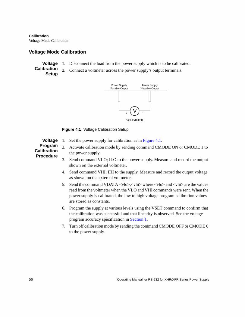
CalibrationVoltage Mode Calibration
56 Operating Manual for RS-232 for XHR/XFR Series Power Supply
Voltage Mode Calibration
VoltageCalibration
Setup
1. Disconnect the load from the power supply which is to be calibrated.2. Connect a voltmeter across the power supply’s output terminals.
Figure 4.1 Voltage Calibration Setup
VoltageProgram
CalibrationProcedure
1. Set the power supply for calibration as in Figure 4.1.2. Activate calibration mode by sending command CMODE ON or CMODE 1 to
the power supply.3. Send command VLO; ILO to the power supply. Measure and record the output
shown on the external voltmeter.4. Send command VHI; IHI to the supply. Measure and record the output voltage
as shown on the external voltmeter.5. Send the command VDATA <vlo>,<vhi> where <vlo> and <vhi> are the values
read from the voltmeter when the VLO and VHI commands were sent. When the power supply is calibrated, the low to high voltage program calibration values are stored as constants.
6. Program the supply at various levels using the VSET command to confirm that the calibration was successful and that linearity is observed. See the voltage program accuracy specification in Section 1.
7. Turn off calibration mode by sending the command CMODE OFF or CMODE 0 to the power supply.
V -+
VOLTMETER
Power Supply Negative Output
Power Supply Positive Output
CalibrationVoltage Mode Calibration
57
VoltageReadback
CalibrationProcedure
1. Set the power supply for calibration as in Figure 4.1.2. Activate calibration mode by sending command CMODE ON or CMODE 1 to
the power supply.3. Send command VRLO; IRLO to the power supply. Wait for the supply to settle.
Measure and record the output shown on the external voltmeter. Send VRLO again.
4. Send VRHI; IRHI to the supply. Wait for the supply to settle. Measure and record the output voltage shown on the external voltmeter. Send VRHI again.
5. Send the command VRDAT <vlo>,<vhi> where <vlo> and <vhi> are the values read from the voltmeter after the VRLO and VRHI commands were sent. The processor calculates the offset value required to calibrate the power supply. When the power supply is calibrated, the low to high voltage readback calibration values (offsets) are stored as constants.
6. Use commands VSET and VOUT? commands to confirm that the calibration was successful and that linearity is observed. Refer to the voltage readback accuracy specification in Section 1.
7. Turn off calibration mode by sending the command CMODE OFF or CMODE 0 to the power supply.
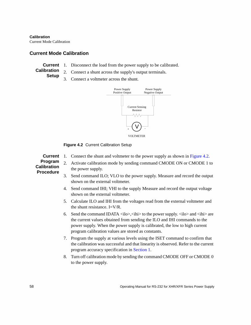
CalibrationCurrent Mode Calibration
58 Operating Manual for RS-232 for XHR/XFR Series Power Supply
Current Mode Calibration
CurrentCalibration
Setup
1. Disconnect the load from the power supply to be calibrated.2. Connect a shunt across the supply's output terminals.3. Connect a voltmeter across the shunt.
Figure 4.2 Current Calibration Setup
CurrentProgram
CalibrationProcedure
1. Connect the shunt and voltmeter to the power supply as shown in Figure 4.2.2. Activate calibration mode by sending command CMODE ON or CMODE 1 to
the power supply.3. Send command ILO; VLO to the power supply. Measure and record the output
shown on the external voltmeter.4. Send command IHI; VHI to the supply Measure and record the output voltage
shown on the external voltmeter.5. Calculate ILO and IHI from the voltages read from the external voltmeter and
the shunt resistance. I=V/R.6. Send the command IDATA <ilo>,<ihi> to the power supply. <ilo> and <ihi> are
the current values obtained from sending the ILO and IHI commands to the power supply. When the power supply is calibrated, the low to high current program calibration values are stored as constants.
7. Program the supply at various levels using the ISET command to confirm that the calibration was successful and that linearity is observed. Refer to the current program accuracy specification in Section 1.
8. Turn off calibration mode by sending the command CMODE OFF or CMODE 0 to the power supply.
V -+
VOLTMETER
Power Supply Negative Output
Power Supply Positive Output
Current Sensing Resistor
CalibrationCurrent Mode Calibration
59
CurrentReadback
CalibrationProcedure
1. Connect the current shunt and voltmeter to the power supply as shown in Figure 4.2.
2. Activate calibration mode by sending command CMODE ON or CMODE 1 to the power supply.
3. Send command IRLO; VRLO to the power supply. Wait for the supply to settle. Measure and record the output voltage shown on the external voltmeter. Send IRLO again.
4. Send command IRHI; VRHI to the supply. Wait for the supply to settle. Measure and record the output voltage shown on the external voltmeter. Send IRHI again.
5. Calculate IRLO and IRHI from the voltages taken from the external voltmeter and the shunt resistance. I=V/R.
6. Send the command IRDAT <ilo>,<ihi> to the power supply. <ilo> and <ihi> are the current values obtained from sending the IRLO and IRHI commands to the power supply. When the power supply is calibrated, the low to high current readback calibration values are stored as constants.
7. Program the supply at various levels using the ISET command to confirm that the calibration was successful and that linearity is observed. Refer to the current readback accuracy specification in Section 1.
8. Turn off calibration mode by sending the command CMODE OFF or CMODE 0 to the power supply.
CalibrationOver Voltage Protection (OVP) Calibration
60 Operating Manual for RS-232 for XHR/XFR Series Power Supply
Over Voltage Protection (OVP) Calibration
We recommend that you perform OVP calibration every six months. Connecting a digital voltmeter as in “Voltage Calibration Setup” is optional.
1. Disconnect all loads from the power supply.2. Ensure that jumper J65 on the interface PCB is CLOSED to enable remote OVP
calibration (Jumper J65 is closed at the factory). See Figure 2.3 RS-232 Interface PCB, p. 22 for the location on the PCB of jumper J65.
3. Activate calibration mode by sending command CMODE ON or CMODE 1 to the power supply.
4. Send the command OVCAL to the power supply. The ADDR LED will light during OVP calibration. Calibration is complete when the ADDR LED turns off. This may take a few minutes.
5. Use the OVSET, OVSET?, and VSET commands to trip the OVP level, confirming that the calibration was successful. When you trip the OVP level, the red OVP LED will light and the voltage will drop to zero. Send the command RST to clear the OVP condition. Refer to the OVP program accuracy specification in Section 1.
6. Turn off calibration mode by sending the command CMODE OFF or CMODE 0 to the power supply.
![Team : Alfa Faridh Suni [232 07 052] Alvani Wiwoho [232 07 163] Harold Harriman [232 07 088] Uray Lunar Meiviar [232 07 164]](https://static.fdocuments.in/doc/165x107/56649c7b5503460f9492ee5a/team-alfa-faridh-suni-232-07-052-alvani-wiwoho-232-07-163-harold-harriman.jpg)


![fVIif.k;k¡ ljy jSf[kd xfr - National Institute of Open Schooling · HkkSfrdh 37 ljy jSf[kd xfr ekWM~;wy - 1 xfr] cy ,oa ÅtkZ fVIif.k;k¡ gy: fn;k gS x = 20t2 è;ku nsa x dk ek=kd](https://static.fdocuments.in/doc/165x107/604962ecde26c0121653f8b3/fviifkk-ljy-jsfkd-xfr-national-institute-of-open-schooling-hkksfrdh-37-ljy.jpg)
![iPphl cksy dk FkksdM+k - sadhumargi.com · 4: Pachchees bol Pachchees bol : 5 igys cksys xfr 444 P AHALE BOLE GA TI 4 ujd xfr] fr;Zap xfr] euq"; xfr vkSj nso xfrA Narak gati, Tiryanch](https://static.fdocuments.in/doc/165x107/5b885b077f8b9a3d028d0f8c/ipphl-cksy-dk-fkksdmk-4-pachchees-bol-pachchees-bol-5-igys-cksys-xfr-444.jpg)