Internal Limiting Membrane laye r visualization and ...rht/RHT Papers/2010/SPIE Ophtalmology 2010 -...
4
Internal Limiting Membrane layer visualization and vitreoretinal surgery guidance using a Common-Path OCT integrated microsurgical tool Xuan Liu 1 *, Eric Meisne 2 , Jae-Ho Han 1 , Kang Zhang 1 , Peter Gehlbach 3 , Russell Taylor 2 , and Jin U. Kang 1 1 Department of Electrical and Computer Engineering 2 Department of Computer Science 3 Wilmer Eye Institute, School of Medicine Johns Hopkins University ABSTRACT Contemporary retinal microsurgery is performed by skilled surgeons through operating microscopes, utilizing free hand techniques and manually operated micro-instruments. One technically challenging procedure is the incising and peeling of the internal limiting membrane (ILM) while minimizing damage to the underlying retina. One strategy for minimizing damage is to improve visualization of the ILM layer. Here we present a preliminary evaluation of a prototype tool that integrates an ultra high resolution Fourier domain common path Optical Coherence Tomography (OCT) with an intelligent microsurgical instrument. The tool provides OCT guided visualization of the ILM layer at the point of tissue contact by the surgical tool. We have evaluated the imaging properties of the common path OCT system. The common path OCT system used in this study has a maximum imaging depth of 1.3mm and a sensitivity of 91dB. We have achieved an experimental axial resolution of 3μm in air and this appears to be sufficient to both identify the ILM and to perform surgical maneuvers. We scanned the single mode fiber probe using an intelligent microsurgical instrument to form B-Mode images. We imaged a porcine eye with both anterior eye segment and the vitreous removed. The image obtained show distinct functional layers of retina. Keywords: Optical Coherence Tomography, Common Path, Vitreoretinal surgery, surgical tool 1. INTRODUCTION Vitreoretinal surgery is challenging because surgeons have to perform extremely precise maneuvers in a limited space. One surgical task is the incising and peeling of the internal limiting membrane (ILM) that is involved in the treatment of macular hole. The ILM peeling is difficult because the ILM is a transparent thin layer and invisible under microscope. To minimize the damage to the underneath tissue when peeling the ILM, it requires a better visualization of ILM. The standard way to improve the visibility is to stain ILM with dye, such as indocyanine green (ICG) dye. Although staining the ILM improves anatomic success in the treatment of macular hole, it leads to unfavorable visual acuity outcome and peripheral visual field loss [1]. Alternatively, instead of using ICG dye, we adopt OCT to increase the visibility of ILM, because OCT can “see” the ILM based on the refractive index contrast between the ILM and the underneath tissue. Using OCT to assist surgeons with A-mode or B-mode scan has been one of our research focuses [2, 3]. To use OCT to guide the procedure of ILM peeling, it requires a high spatial resolution, for the ILM is as thin as 1-3 microns. We adopt the common path configuration in our OCT system, because common path OCT (CP OCT) can achieve ultra high resolution at very low cost [5, 6]. To achieve high resolution, we use a broadband source to illuminate the common path interferometer. The broadband source constitutes three superluminescent diodes (SLD), Ophthalmic Technologies XX, edited by Fabrice Manns, Per G. Söderberg, Arthur Ho, Proc. of SPIE Vol. 7550, 755003 · © 2010 SPIE · CCC code: 1605-7422/10/$18 · doi: 10.1117/12.840976 Proc. of SPIE Vol. 7550 755003-1 Downloaded from SPIE Digital Library on 13 Jan 2011 to 128.220.160.6. Terms of Use: http://spiedl.org/terms
Transcript of Internal Limiting Membrane laye r visualization and ...rht/RHT Papers/2010/SPIE Ophtalmology 2010 -...
Internal Limiting Membrane layer visualization and vitreoretinal
surgery guidance using a Common-Path OCT integrated microsurgical tool
Xuan Liu1*, Eric Meisne2, Jae-Ho Han1, Kang Zhang1, Peter Gehlbach 3, Russell Taylor2,
and Jin U. Kang1 1Department of Electrical and Computer Engineering
2Department of Computer Science 3Wilmer Eye Institute, School of Medicine
Johns Hopkins University
ABSTRACT
Contemporary retinal microsurgery is performed by skilled surgeons through operating microscopes, utilizing free hand techniques and manually operated micro-instruments. One technically challenging procedure is the incising and peeling of the internal limiting membrane (ILM) while minimizing damage to the underlying retina. One strategy for minimizing damage is to improve visualization of the ILM layer. Here we present a preliminary evaluation of a prototype tool that integrates an ultra high resolution Fourier domain common path Optical Coherence Tomography (OCT) with an intelligent microsurgical instrument. The tool provides OCT guided visualization of the ILM layer at the point of tissue contact by the surgical tool. We have evaluated the imaging properties of the common path OCT system. The common path OCT system used in this study has a maximum imaging depth of 1.3mm and a sensitivity of 91dB. We have achieved an experimental axial resolution of 3μm in air and this appears to be sufficient to both identify the ILM and to perform surgical maneuvers. We scanned the single mode fiber probe using an intelligent microsurgical instrument to form B-Mode images. We imaged a porcine eye with both anterior eye segment and the vitreous removed. The image obtained show distinct functional layers of retina.
Keywords: Optical Coherence Tomography, Common Path, Vitreoretinal surgery, surgical tool
1. INTRODUCTION Vitreoretinal surgery is challenging because surgeons have to perform extremely precise maneuvers in a limited space. One surgical task is the incising and peeling of the internal limiting membrane (ILM) that is involved in the treatment of macular hole. The ILM peeling is difficult because the ILM is a transparent thin layer and invisible under microscope. To minimize the damage to the underneath tissue when peeling the ILM, it requires a better visualization of ILM. The standard way to improve the visibility is to stain ILM with dye, such as indocyanine green (ICG) dye. Although staining the ILM improves anatomic success in the treatment of macular hole, it leads to unfavorable visual acuity outcome and peripheral visual field loss [1]. Alternatively, instead of using ICG dye, we adopt OCT to increase the visibility of ILM, because OCT can “see” the ILM based on the refractive index contrast between the ILM and the underneath tissue.
Using OCT to assist surgeons with A-mode or B-mode scan has been one of our research focuses [2, 3]. To use OCT to guide the procedure of ILM peeling, it requires a high spatial resolution, for the ILM is as thin as 1-3 microns. We adopt the common path configuration in our OCT system, because common path OCT (CP OCT) can achieve ultra high resolution at very low cost [5, 6]. To achieve high resolution, we use a broadband source to illuminate the common path interferometer. The broadband source constitutes three superluminescent diodes (SLD),
Ophthalmic Technologies XX, edited by Fabrice Manns, Per G. Söderberg, Arthur Ho, Proc. of SPIE Vol. 7550, 755003 · © 2010 SPIE · CCC code: 1605-7422/10/$18 · doi: 10.1117/12.840976
Proc. of SPIE Vol. 7550 755003-1
Downloaded from SPIE Digital Library on 13 Jan 2011 to 128.220.160.6. Terms of Use: http://spiedl.org/terms
which are multiplexed using fiber-optic couplers. Combining multiple SLDs allows us to have a bandwidth that is comparable with femtosecond laser; however, it is much cheaper and more compact [7]. CP OCT also circumvent another challenge in retinal imaging which is chromatic dispersion that decreases the resolution. The dispersion induced by the eye varies among subjects and requires compensate for. However, in CP OCT, the sample and reference arms share the same optical path and the probe is directly put in close proximity to the sample site of interest. Therefore, the system is essentially free of dispersion mismatch. In our CP OCT system, the probe arm is simply a single mode fiber with 125μm outer diameter if we remove the plastic jacket of the fiber. The miniature size of the probe enables us to integrate the CP OCT probe with surgical tools and insert the probe into the eye while surgeon is performing surgical tasks. In this study, we integrated the fiber probe with CMU Micron [8], an intelligent microsurgical instrument for ophthalmologic microsurgery that can cancel the physiological tremor from the surgeon’s hand as well as can perform high-speed 3-D mechanical scan [9]. OCT can track the motion of tool tip in real time, which can be potentially used to control the motion of the surgical tool. When using the integrated surgical tool as an imaging device, we scan the fiber probe of CP OCT to form B-mode or even C-mode image.
In order to evaluate the integrated surgical tool, we applied different driving waveforms to the surgical tool so that it moved its tip accordingly. OCT was used to sense the motion of tool tip. The results show that OCT can track the tool with high spatial and temporal resolution. On the other hand, we imaged the retina of a porcine eye with CP OCT. The obtained image shows distinct retina layers. Specifically, we observed a thin layer that is probably ILM.
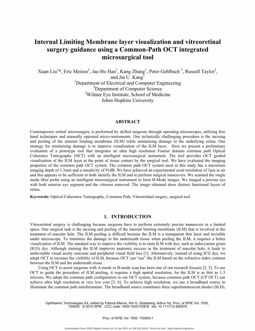
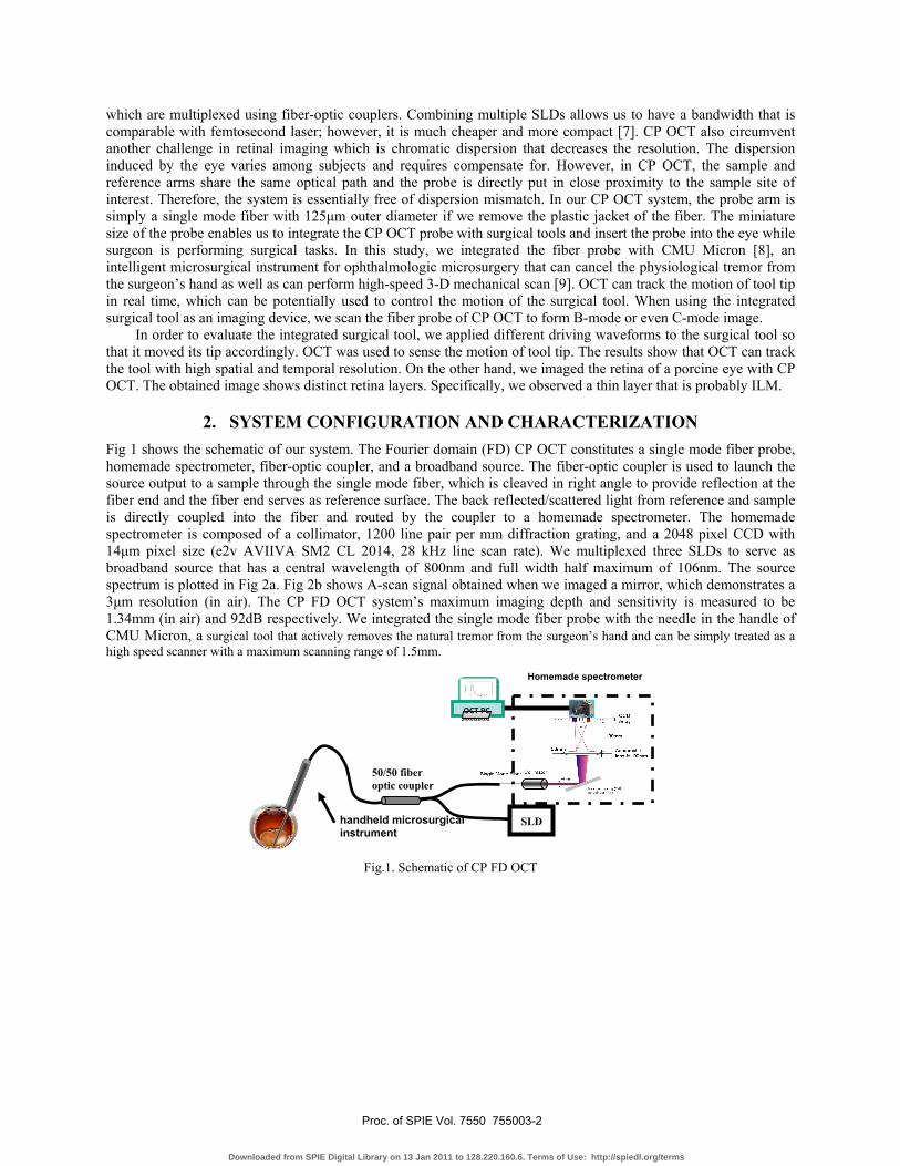
2. SYSTEM CONFIGURATION AND CHARACTERIZATION Fig 1 shows the schematic of our system. The Fourier domain (FD) CP OCT constitutes a single mode fiber probe, homemade spectrometer, fiber-optic coupler, and a broadband source. The fiber-optic coupler is used to launch the source output to a sample through the single mode fiber, which is cleaved in right angle to provide reflection at the fiber end and the fiber end serves as reference surface. The back reflected/scattered light from reference and sample is directly coupled into the fiber and routed by the coupler to a homemade spectrometer. The homemade spectrometer is composed of a collimator, 1200 line pair per mm diffraction grating, and a 2048 pixel CCD with 14μm pixel size (e2v AVIIVA SM2 CL 2014, 28 kHz line scan rate). We multiplexed three SLDs to serve as broadband source that has a central wavelength of 800nm and full width half maximum of 106nm. The source spectrum is plotted in Fig 2a. Fig 2b shows A-scan signal obtained when we imaged a mirror, which demonstrates a 3μm resolution (in air). The CP FD OCT system’s maximum imaging depth and sensitivity is measured to be 1.34mm (in air) and 92dB respectively. We integrated the single mode fiber probe with the needle in the handle of CMU Micron, a surgical tool that actively removes the natural tremor from the surgeon’s hand and can be simply treated as a high speed scanner with a maximum scanning range of 1.5mm.
Fig.1. Schematic of CP FD OCT
Homemade spectrometer
SLD
50/50 fiber optic coupler
OCT PC
handheld microsurgicalinstrument
Proc. of SPIE Vol. 7550 755003-2
Downloaded from SPIE Digital Library on 13 Jan 2011 to 128.220.160.6. Terms of Use: http://spiedl.org/terms
700 750 800 850 9000
0.2
0.4
0.6
0.8
1
wavelength (nm)
sour
ce s
pect
rum
(A.U
.)
Fig. 2. source spectrum Fig. 3. A-scan of the mirror surface
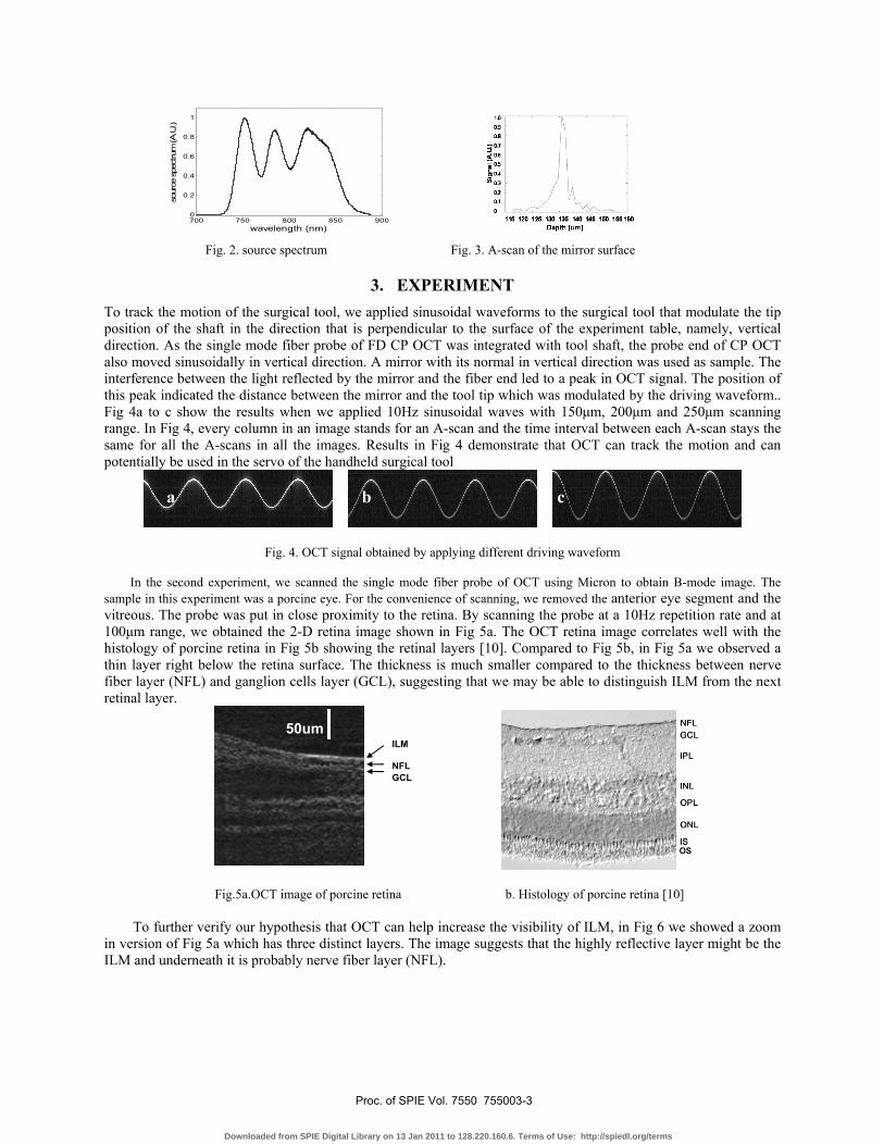
3. EXPERIMENT To track the motion of the surgical tool, we applied sinusoidal waveforms to the surgical tool that modulate the tip position of the shaft in the direction that is perpendicular to the surface of the experiment table, namely, vertical direction. As the single mode fiber probe of FD CP OCT was integrated with tool shaft, the probe end of CP OCT also moved sinusoidally in vertical direction. A mirror with its normal in vertical direction was used as sample. The interference between the light reflected by the mirror and the fiber end led to a peak in OCT signal. The position of this peak indicated the distance between the mirror and the tool tip which was modulated by the driving waveform.. Fig 4a to c show the results when we applied 10Hz sinusoidal waves with 150μm, 200μm and 250μm scanning range. In Fig 4, every column in an image stands for an A-scan and the time interval between each A-scan stays the same for all the A-scans in all the images. Results in Fig 4 demonstrate that OCT can track the motion and can potentially be used in the servo of the handheld surgical tool
Fig. 4. OCT signal obtained by applying different driving waveform
In the second experiment, we scanned the single mode fiber probe of OCT using Micron to obtain B-mode image. The sample in this experiment was a porcine eye. For the convenience of scanning, we removed the anterior eye segment and the vitreous. The probe was put in close proximity to the retina. By scanning the probe at a 10Hz repetition rate and at 100μm range, we obtained the 2-D retina image shown in Fig 5a. The OCT retina image correlates well with the histology of porcine retina in Fig 5b showing the retinal layers [10]. Compared to Fig 5b, in Fig 5a we observed a thin layer right below the retina surface. The thickness is much smaller compared to the thickness between nerve fiber layer (NFL) and ganglion cells layer (GCL), suggesting that we may be able to distinguish ILM from the next retinal layer.
Fig.5a.OCT image of porcine retina b. Histology of porcine retina [10]
To further verify our hypothesis that OCT can help increase the visibility of ILM, in Fig 6 we showed a zoom in version of Fig 5a which has three distinct layers. The image suggests that the highly reflective layer might be the ILM and underneath it is probably nerve fiber layer (NFL).
ILM
NFL GCL
50um
a b c
Proc. of SPIE Vol. 7550 755003-3
Downloaded from SPIE Digital Library on 13 Jan 2011 to 128.220.160.6. Terms of Use: http://spiedl.org/terms
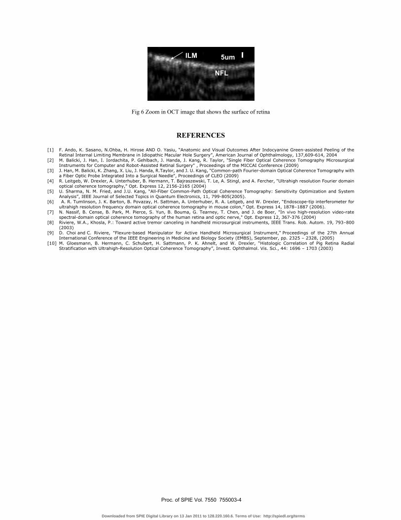
Fig 6 Zoom in OCT image that shows the surface of retina
REFERENCES
[1] F. Ando, K. Sasano, N.Ohba, H. Hirose AND O. Yasiu, “Anatomic and Visual Outcomes After Indocyanine Green-assisted Peeling of the Retinal Internal Limiting Membrane in Idiopathic Macular Hole Surgery”, American Journal of Ophthalmology, 137,609-614, 2004
[2] M. Balicki, J. Han, I. Iordachita, P. Gehlbach, J. Handa, J. Kang, R. Taylor, "Single Fiber Optical Coherence Tomography Microsurgical Instruments for Computer and Robot-Assisted Retinal Surgery" , Proceedings of the MICCAI Conference (2009)
[3] J. Han, M. Balicki, K. Zhang, X. Liu, J. Handa, R.Taylor, and J. U. Kang, "Common-path Fourier-domain Optical Coherence Tomography with a Fiber Optic Probe Integrated Into a Surgical Needle", Proceedings of CLEO (2009)
[4] R. Leitgeb, W. Drexler, A. Unterhuber, B. Hermann, T. Bajraszewski, T. Le, A. Stingl, and A. Fercher, "Ultrahigh resolution Fourier domain optical coherence tomography," Opt. Express 12, 2156-2165 (2004)
[5] U. Sharma, N. M. Fried, and J.U. Kang, “All-Fiber Common-Path Optical Coherence Tomography: Sensitivity Optimization and System Analysis”, IEEE Journal of Selected Topics in Quantum Electronics, 11, 799-805(2005).
[6] A. R. Tumlinson, J. K. Barton, B. Povazay, H. Sattman, A. Unterhuber, R. A. Leitgeb, and W. Drexler, “Endoscope-tip interferometer for ultrahigh resolution frequency domain optical coherence tomography in mouse colon,” Opt. Express 14, 1878–1887 (2006).
[7] N. Nassif, B. Cense, B. Park, M. Pierce, S. Yun, B. Bouma, G. Tearney, T. Chen, and J. de Boer, "In vivo high-resolution video-rate spectral-domain optical coherence tomography of the human retina and optic nerve," Opt. Express 12, 367-376 (2004)
[8] Riviere, W.A., Khosla, P.: Toward active tremor canceling in handheld microsurgical instruments, IEEE Trans. Rob. Autom. 19, 793–800 (2003)
[9] D. Choi and C. Riviere, "Flexure-based Manipulator for Active Handheld Microsurgical Instrument," Proceedings of the 27th Annual International Conference of the IEEE Engineering in Medicine and Biology Society (EMBS), September, pp. 2325 – 2328, (2005)
[10] M. Gloesmann, B. Hermann, C. Schubert, H. Sattmann, P. K. Ahnelt, and W. Drexler, “Histologic Correlation of Pig Retina Radial Stratification with Ultrahigh-Resolution Optical Coherence Tomography”, Invest. Ophthalmol. Vis. Sci., 44: 1696 – 1703 (2003)
5um
NFL
ILM
Proc. of SPIE Vol. 7550 755003-4
Downloaded from SPIE Digital Library on 13 Jan 2011 to 128.220.160.6. Terms of Use: http://spiedl.org/terms