Internal Gear Unit - bucherhydraulics.com · 100-P-000225-EN-02/03.2018 Internal Gear Unit QXEM...
16
1/16 Reference: 100-P-000225-EN-02 Issue: 03.2018 Internal Gear Unit for motor/pump function Series QXEM
Transcript of Internal Gear Unit - bucherhydraulics.com · 100-P-000225-EN-02/03.2018 Internal Gear Unit QXEM...

1/16
Reference: 100-P-000225-EN-02
Issue: 03.2018
Internal Gear Unitfor motor/pump functionSeries QXEM

100-P-000225-EN-02/03.2018Internal Gear Unit QXEM
2/16

100-P-000225-EN-02/03.2018Internal Gear Unit QXEM
3/16
Contents Page
1 General 5. . . . . . . . . . . . . . . . . . . . . . . . . . . . . . . . . . . . . . . . . . . . . . . . . . . . . . . . . . . . . . . . . . . . . . . . . . . .
1.1 Product description 5. . . . . . . . . . . . . . . . . . . . . . . . . . . . . . . . . . . . . . . . . . . . . . . . . . . . . . . . . . . .
1.2 Advantages 5. . . . . . . . . . . . . . . . . . . . . . . . . . . . . . . . . . . . . . . . . . . . . . . . . . . . . . . . . . . . . . . . . .
1.3 Application 5. . . . . . . . . . . . . . . . . . . . . . . . . . . . . . . . . . . . . . . . . . . . . . . . . . . . . . . . . . . . . . . . . . .
2 Technical data 5. . . . . . . . . . . . . . . . . . . . . . . . . . . . . . . . . . . . . . . . . . . . . . . . . . . . . . . . . . . . . . . . . . . . . .
2.1 General 5. . . . . . . . . . . . . . . . . . . . . . . . . . . . . . . . . . . . . . . . . . . . . . . . . . . . . . . . . . . . . . . . . . . . . .
2.2 Main characteristics 6. . . . . . . . . . . . . . . . . . . . . . . . . . . . . . . . . . . . . . . . . . . . . . . . . . . . . . . . . . .
3 Performance graphs 7. . . . . . . . . . . . . . . . . . . . . . . . . . . . . . . . . . . . . . . . . . . . . . . . . . . . . . . . . . . . . . . . .
3.1 Minimum speed limit for pump and motor operation 7. . . . . . . . . . . . . . . . . . . . . . . . . . . . . . . .
3.2 Noise level 7. . . . . . . . . . . . . . . . . . . . . . . . . . . . . . . . . . . . . . . . . . . . . . . . . . . . . . . . . . . . . . . . . . .
3.3 Efficiency (ƞ) 9. . . . . . . . . . . . . . . . . . . . . . . . . . . . . . . . . . . . . . . . . . . . . . . . . . . . . . . . . . . . . . . . .
3.4 Starting torque 9. . . . . . . . . . . . . . . . . . . . . . . . . . . . . . . . . . . . . . . . . . . . . . . . . . . . . . . . . . . . . . . .
4 Dimensions 10. . . . . . . . . . . . . . . . . . . . . . . . . . . . . . . . . . . . . . . . . . . . . . . . . . . . . . . . . . . . . . . . . . . . . . . .
5 Ordering details 11. . . . . . . . . . . . . . . . . . . . . . . . . . . . . . . . . . . . . . . . . . . . . . . . . . . . . . . . . . . . . . . . . . . . .
5.1 Ordering example 11. . . . . . . . . . . . . . . . . . . . . . . . . . . . . . . . . . . . . . . . . . . . . . . . . . . . . . . . . . . . .
5.2 Standard configuration 11. . . . . . . . . . . . . . . . . . . . . . . . . . . . . . . . . . . . . . . . . . . . . . . . . . . . . . . . .
5.3 Options 11. . . . . . . . . . . . . . . . . . . . . . . . . . . . . . . . . . . . . . . . . . . . . . . . . . . . . . . . . . . . . . . . . . . . . .
5.4 Direction of rotation 11. . . . . . . . . . . . . . . . . . . . . . . . . . . . . . . . . . . . . . . . . . . . . . . . . . . . . . . . . . . .
6 Fluid cleanliness 12. . . . . . . . . . . . . . . . . . . . . . . . . . . . . . . . . . . . . . . . . . . . . . . . . . . . . . . . . . . . . . . . . . . .
7 Note 12. . . . . . . . . . . . . . . . . . . . . . . . . . . . . . . . . . . . . . . . . . . . . . . . . . . . . . . . . . . . . . . . . . . . . . . . . . . . . . .
8 Fluid cleanliness 12. . . . . . . . . . . . . . . . . . . . . . . . . . . . . . . . . . . . . . . . . . . . . . . . . . . . . . . . . . . . . . . . . . . .
9 Operational reliability 12. . . . . . . . . . . . . . . . . . . . . . . . . . . . . . . . . . . . . . . . . . . . . . . . . . . . . . . . . . . . . . . .
10 Accessories 13. . . . . . . . . . . . . . . . . . . . . . . . . . . . . . . . . . . . . . . . . . . . . . . . . . . . . . . . . . . . . . . . . . . . . . . .
10.1 Bolt-on valves - SAE J518 code 61 / ISO 6162-1 pattern 13. . . . . . . . . . . . . . . . . . . . . . . . . . . .
10.2 Pipe flanges - high pressure type 14. . . . . . . . . . . . . . . . . . . . . . . . . . . . . . . . . . . . . . . . . . . . . . . .
10.3 Pipe flanges - high pressure type 15. . . . . . . . . . . . . . . . . . . . . . . . . . . . . . . . . . . . . . . . . . . . . . . .

100-P-000225-EN-02/03.2018Internal Gear Unit QXEM
4/16

100-P-000225-EN-02/03.2018Internal Gear Unit QXEM
5/16
1 General
1.1 Product description
For applications requiring variable-speed multi-quadrantoperation, Bucher Hydraulics has developed a specialversion: The QXEM internal gear unit.
One of the central points in the QXEM series is itssymmetric construction, with identical high and lowpressure areas. With special metering grooves andlubrication systems as well as two same-size pressure-tightconnections, the design is specially optimised for 2 and 4quadrant modes and is thus ideally suited to both directionsof rotation at high and low pressures.
Thanks to the use of high-precision gear parts with a pinionshaft (pinion and shaft as one component), extremely lowpulsation levels are produced even at low speeds.
1.2 Advantages
� compact, non-compensated design
� pressure and flow pulsations are minimal, thanks to
pinion-shaft technology
� first-rate reliability at both high and low speeds and in
reverse mode
� field-proven in both fixed- and variable-speed drive
� long service life even under highly cyclical loading
� change of direction in the milliseconds range
(pinion shaft)
� suitable for special fluids such as HFB, HFC, HFD and
bio-degradables
Low-/highpressurezone
High-/lowpressurezone
Gear ring
Crescent
Pinion
1.3 Application
� Injection molding machines
� Hydraulic presses
� Waste compactors
� Die casting machines
2 Technical data
2.1 General
Characteristics Unit Description, value
Installation attitude unrestricted
Mounting method (standard) oval 2-hole flange to ISO 3019/1 (SAE): QXEM 3-6oval 2-hole flange to ISO 3019/2 (metric) QXEM 2+8
Direction of rotation unrestricted
Drive method in-line, by a flexible coupling
Hydraulic fluid HLP mineral oils to DIN 51524, Part 2HFB, HFD and HFC fluids to VDMA 24317 (other on request)
Max. admissible level of contamination ofthe hydraulic fluid
ISO 4406 class 20/18/15
Operating viscosityStarting viscosity
mm2/s 10 … 10010 … 300 (higher values on request)

100-P-000225-EN-02/03.2018Internal Gear Unit QXEM
6/16
Characteristics Unit Description, value
Hydraulic fluid temperature range °C min -20 / max +80 (but comply with viscosity limits)ideal range: +30 … +60 / option 09: -20°C … +100°C
Max. pressure at drain port bar 1.5 absolute (higher values on request)
Accumulated pressure restriction port P1 + port P2 � continuous pressure
Seal material NBR = standardFPM (Viton) = option 09
2.2 Main characteristics
IMPORTANT: The main characteristics are valid for hydraulic oils DIN 51524 with a viscosity of 42mm2/s.
TypeDisplacement
[cm3/U]maximum Speed
[min-1]Operating pressure
[bar]Torque 3)
[Nm]
nominal effective 1)Pump
operat. 4)
Motor
operating
conti-
nuous
intermit-
tent 2)
QXEM22-005QXEM22-006QXEM22-008
005006008
5,16,37,9
3250 6000 210 2501721
26,5
QXEM32-010QXEM32-012QXEM32-016
010012016
10,012,615,6
3050 5500 210 25033,54252
QXEM42-020QXEM42-025QXEM42-032
020025032
20,325,132,3
2900 5000 210 2506884108
QXEM52-040QXEM52-050QXEM52-063
040050063
39,150,363,4
2500 4500 210 250131169212
QXEM62-080QXEM62-100QXEM62-125
080100125
79,8100,5124,2
225020501800
4000 210 250268337416
QXEM82-160QXEM82-200QXEM82-250
160200250
161,9200,0247,7
160015001350
3500 210 250544671832
1) Due to manufacturing tolerances, there may be slight variations in the displacement.
2) Intermittent pressure for max. 20 sec/min but not more than 10% of the duty cycle.
3) Theoretical value at the maximum permitted continuous pressure. For starting torques, see section 3.
4) Minimum inlet pressure 0,98 bar absolute.
100-P-000225-EN-02/03.2018Internal Gear Unit QXEM
7/16
3 Performance graphs
3.1 Minimum speed limit for pump and motor operation
100
200
300
400
500
p [bar]
n [
min
-1]
…nmax
0
600
700
800
900
1000
0 50 100 150 200 250
continuous operation
intermittent operation 1)
intermittent operation of max. 5 sec.
intermittent operation of max. 2 sec.
1) Intermittent pressure for max. 20 sec/min but not more than 10% of the duty cycle.
3.2 Noise level
Measured to DIN 45635 part 26 in low-echo noise measurement chamber,valid for single units with deviations of ± 1,5 dB [A].
3.2.1 QXEM22
82,5 - 85,080,0 - 82,577,5 - 80,075,0 - 77,572,5 - 75,070,0 - 72,567,5 - 70,065,0 - 67,562,5 - 65,060,0 - 62,557,5 - 60,055,0 - 57,552,5 - 55,050,0 - 52,547,5 - 50,045,0 - 47,542,5 - 45,040,0 - 42,537,5 - 40,035,0 - 37,532,5 - 35,0
dB [A]
250 200 150 100 50
20
6000
5500
5000
4500
4000
3500
3000
2500
2000
1500
1000
500
p [bar]
n [min-1]
20
3.2.2 QXEM32
82,5 - 85,080,0 - 82,577,5 - 80,075,0 - 77,572,5 - 75,070,0 - 72,567,5 - 70,065,0 - 67,562,5 - 65,060,0 - 62,557,5 - 60,055,0 - 57,552,5 - 55,050,0 - 52,547,5 - 50,045,0 - 47,542,5 - 45,040,0 - 42,537,5 - 40,035,0 - 37,532,5 - 35,0
dB [A]
p [bar]
n [min-1]
250 200 150 100 50
5500
5000
4500
4000
3500
3000
2500
2000
1500
1000
50020

100-P-000225-EN-02/03.2018Internal Gear Unit QXEM
8/16
3.2.3 QXEM42
77,5 - 80,075,0 - 77,572,5 - 75,070,0 - 72,567,5 - 70,065,0 - 67,562,5 - 65,060,0 - 62,557,5 - 60,055,0 - 57,552,5 - 55,050,0 - 52,547,5 - 50,045,0 - 47,542,5 - 45,040,0 - 42,537,5 - 40,0
dB [A]
250 200 150 100 50 20
5000
4500
4000
3500
3000
2500
2000
1500
1000
500
p [bar]
n [min-1]
3.2.4 QXEM52
80,0 - 82,577,5 - 80,075,0 - 77,572,5 - 75,070,0 - 72,567,5 - 70,065,0 - 67,562,5 - 65,060,0 - 62,557,5 - 60,055,0 - 57,552,5 - 55,050,0 - 52,547,5 - 50,045,0 - 47,542,5 - 45,0
dB [A]
250 200 150 100 50 20
4500
4000
3500
3000
2500
2000
1500
1000
500
p [bar]
n [min-1]
3.2.5 QXEM62
77,5 - 80,075,0 - 77,572,5 - 75,070,0 - 72,567,5 - 70,065,0 - 67,562,5 - 65,060,0 - 62,557,5 - 60,055,0 - 57,552,5 - 55,050,0 - 52,547,5 - 50,045,0 - 47,542,5 - 45,0
dB [A]
20
4000
3500
3000
2500
2000
1500
1000
500
p [bar]
n [min-1]
250 200 150 100 50
3.2.6 QXEM82
77,5 - 80,075,0 - 77,572,5 - 75,070,0 - 72,567,5 - 70,065,0 - 67,562,5 - 65,060,0 - 62,557,5 - 60,055,0 - 57,552,5 - 55,050,0 - 52,547,5 - 50,045,0 - 47,5
dB [A]
20
3500
3000
2500
2000
1500
1000
500
p [bar]
n [min-1]
250 200 150 100 50
100-P-000225-EN-02/03.2018Internal Gear Unit QXEM
9/16
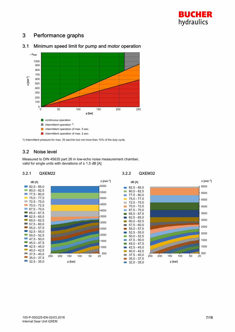
3.3 Efficiency (ƞ)
Measured with viscosity 42 mm2/s, speed 1450 min-1,
Solid line = continous pressure / dashed line = max. intermittent pressure
3.3.1 Volumetric efficiency
0 50 100 150 200 25070
80
90
100
82625242
32
22
pΔ [bar]
ƞvol [
%]
3.3.2 Hydro-mechanical efficiency
0 50 100 150 200 25070
80
90
100826252423222
ƞhm
[%
]
pΔ [bar]
3.4 Starting torque
3.4.1 QXEM22
005006
008
40
20
00 50 100 150 200 250
10
30
pΔ [bar]
M [N
m]
3.4.2 QXEM32
60
40
20
00 50 100 150 200
010
012
016
250
pΔ [bar]
M [N
m]
3.4.3 QXEM42
80
60
40
20
00 50 100 150 200
100
120
020
025
032
250
pΔ [bar]
M [N
m]
3.4.4 QXEM52
200
100
0
040
050
063
0 50 100 150 200 250
50
150
pΔ [bar]
M [N
m]
3.4.5 QXEM62
400
300
200
100
0
080
100
125
0 50 100 150 200 250
pΔ [bar]
M [N
m]
3.4.6 QXEM82
400
200
0
600
160
200
250800
50 100 150 200 2500
M [N
m]
pΔ [bar]

100-P-000225-EN-02/03.2018Internal Gear Unit QXEM
10/16
4 Dimensions
Frame size 2 3 4 5 6 8
Pressure range 2 2 2 2 2 2
Service ports to SAE J518 1) P1, P2G1/2“ 3)
threadG 3/4” 3)
thread 1” 1¼“ 1½“ 2”
Drain port to DIN 3852 Part 2 PL G ¼“ G ¼“ G ¼“ G ¼“ G ⅜“ G ½“
Mounting: oval2-hole flange to ISO 3019/1(SAE - size 3-6)
ISO 3019/2(Metr. - sizes 2+8)
A 118 132 170 212 267 330
B(SAE) - 106 146 181 229 -
B(Metr.) 100 109 140 180 224 280
C 9 11 14 18 22 26
N(SAE) - 82,55 -0,05 101,6 -0,05 127 -0,05 152,4 -0,05 -
N(Metr.) 63 h8 80 h8 100 h8 125 h8 160 h8 200 h8
O 8,5 8,5 10,5 12,5 16,5 20
V 6 6 7 7 7 9
Mounting: oval2-hole flange to ISO 3019/1(SAE - size 3-6)
ISO 3019/2(Metr. - sizes 2+8)
X(��) 9 9 12 14 18 22
Y(Metr.) 85 103 125 160 200 250
Shaft end: cylindrical,to ISO/R775 2)
D 16 j6 20 j6 25 j6 32 j6 40 j6 50 j6
E 28 36 42 58 82 110
F 5 6 8 10 12 14
G 18 22,5 28 35 43 53,5
I 37 44 51 68 92 122
Housing
K 37,5 44 52,5 60,5 74 90
L 121,5 145,5 177,5 211,5 249 314
T1 43 53,5 67 88,5 110 138
T2 43 60 70 88,5 110 138
Z 100 120 125 156 195 250
Weight kg 5,2 9,6 17,3 30,2 56,5 111,3
1) For SAE J518 code 61 bzw. ISO6162-1 pipe flange dimensions see section 10.
2) For other shaft ends, contact Bucher Hydraulics.
3) Threaded ports to DIN 3852 Part 2.
1
P1
E
T2
F
B
L
K
I
D
T1
P1/P2
G
Z
A
C
O
N
V
P2
PL
1 Option 66 = 4-hole mounting flange ISO 3019/2

100-P-000225-EN-02/03.2018Internal Gear Unit QXEM
11/16
5 Ordering details
N5 0 4 02Q X M - * * *E
Internal gear unit QXEM
Frame size 2 / 3 / 4 / 5 / 6 / 8
Pressure range 2
Geom. Displ./Consump. [cm3/rev] 5,1 - 247,7
Direction of rotation, unrestricted N (see section 5.4)
Options (to be inserted by the factory, see section 5.3 for a selection)
5.1 Ordering example
Required: Internal gear unit QXEMDispl./Consump.: 40 cm3/revContinuous pressure: 210 barFor use with mineral oil: HLPOrdering code: QXEM 52-040 N
5.2 Standard configuration
� Direction of rotation - unrestricted
� 2-hole mounting flange to ISO 3019/1;Frame size QXEM 3-62-hole mounting flange to ISO 3019/2;Frame size QXEM 2+8
� Nitrile seals
� Cylindrical shaft end to ISO R775
� Separate drain port in rear cover of the drive unit
� Ports P1 + P2 both the same size
� High pressure shaft seal
� Black priming, flange without priming
5.3 Options
-O = without priming
09 = FPM(Viton) seals, without priming
66 = 4-hole mounting flange to ISO 3019/2 (metric)
130 = 2-quadrant operation, service port dimensionsas per QX pumps2-hole mounting flange to ISO 3019/2 (metric)
For other special features, contact Bucher Hydraulics.
5.4 Direction of rotation
Direction of rotation: right:
(clockwise, viewed from the shaft end) = oil flows from P1to P2
Direction of rotation: left:
(counterclockwise , viewed from the shaft end) = oil flowsfrom P2 to P1

100-P-000225-EN-02/03.2018Internal Gear Unit QXEM
12/16
6 Fluid cleanliness
QXEM internal gear units require a fluid with a minimumcleanliness level of ISO 4406 code 20/18/15.We recommend the use of fluids that contain anti-wear additives for mixed-friction operating conditions. Fluids without appropriate additives can reduce the service life ofpumps and motors. The user is responsible for maintaining,and regularly checking, the fluid quality. Bucher Hydraulicsrecommends a load capacity of > 30 N/mm2 to Brugger DIN51347-2.
7 Note
This catalogue is intended for users with specialist knowledge. The user must check the suitability of the equipmentdescribed herein in order to ensure that all of the conditionsnecessary for the safety and proper functioning of the system are fulfilled. If you have any doubts or questions concerning the use of these pumps, please consult Bucher Hydraulics.
8 Fluid cleanliness
Cleanliness class (RK) as per ISO 4406
CodeISO 4406
Dirt particle number / 100 ml
≥ 4 m ≥ 6 m ≥ 14 m
23/21/18 8000000 2000000 250000
22/20/18 4000000 1000000 250000
22/20/17 4000000 1000000 130000
22/20/16 4000000 1000000 64000
21/19/16 2000000 500000 64000
20/18/15 1000000 250000 32000
19/17/14 500000 130000 16000
18/16/13 250000 64000 8000
17/15/12 130000 32000 4000
16/14/12 64000 16000 4000
16/14/11 64000 16000 2000
15/13/10 32000 8000 1000
14/12/9 16000 4000 500
13/11/8 8000 2000 250
9 Operational reliability
To ensure a reliable operation and a long service life of theQXEM internal gear units, a maintenance schedule must beprepared for the power unit, machine or system. The maintenance schedule must make sure that the provided or permissible operating conditions of the QXEM internal gearunits are adhered to over the period of use.In particular, compliance with the following operating parameters must be ensured:– The required oil cleanliness– The operating temperature range– The fluid levelMoreover, the QXEM internal gear units and the systemmust be inspected at regular intervals for changes in the following parameters:– Vibration– Noise– Differential temperature of internal gear unit – fluid in the tank– Foaming in the tank– Freedom from leakageChanges in these parameters indicate wear of components(e.g. drive motor, coupling, internal gear unit, etc.). Thecause must be immediately pinpointed and eliminated.To provide high operational reliability of the QXEM internalgear unit in the machine or system, we recommend continuous, automatic checks of the above parameters and anautomatic shutdown in the case of changes that exceed theusual fluctuations within the provided operating range.
Commissioning see operating instructions 100-B-000014

100-P-000225-EN-02/03.2018Internal Gear Unit QXEM
13/16
10 Accessories
10.1 Bolt-on valves - SAE J518 code 61 / ISO 6162-1 pattern
Pressure relief valve Pressure relief valvesolenoid control
Accumulator charging valve
A DF SG A DAS
G AGSF
P T
M
Z
P T
M
Z
P T
M
Z
Technical data sheet100-P-000123
Technical data sheet100-P-000119
Technical data sheet100-P-0000124
10.1.1 Examples for mounted bolt-on valves
Bolt-on valve with threaded ports
AGDF
Bolt-on valves with pipe flanges SAE1)
ASDF+RF
Bolt-on valve with pipe flanges SAE+ RVSAE2)
ASDF+RF+RVSAE+DPSAE+ZPSAE
1) Pipe flange see section 10.2 and 10.3.
2) Please ask Bucher Hydraulics GmbH for check valves.
IMPORTANT: Detailed information for bolt-on valves see www.bucherhydraulics.com
100-P-000225-EN-02/03.2018Internal Gear Unit QXEM
14/16
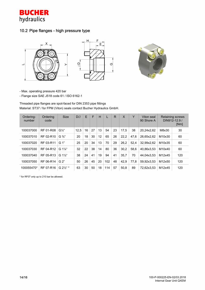
10.2 Pipe flanges - high pressure type
HE
D GY
X
R
L
F
- Max. operating pressure 420 bar
- Flange size SAE J518 code 61 / ISO 6162-1
Threaded pipe flanges are spot-faced for DIN 2353 pipe fittings
Material: ST37 / for FPM (Viton) seals contact Bucher Hydraulics GmbH.
Orderingnumber
Orderingcode
Size D E F H L R X Y Viton seal90 Shore A
Retaining screwsDIN912-12.9 / [Nm]
100037000 RF 01-R08 G½“ 12,5 16 27 13 54 23 17,5 38 20,24x2,62 M8x30 30
100037010 RF 02-R10 G ¾“ 20 18 30 12 65 26 22,2 47,6 26,65x2,62 M10x30 60
100037020 RF 03-R11 G 1” 25 20 34 13 70 29 26,2 52,4 32,99x2,62 M10x35 60
100037030 RF 04-R12 G 1¼“ 32 22 38 14 80 36 30,2 58,6 40,86x3,53 M10x40 60
100037040 RF 05-R13 G 1½“ 38 24 41 19 94 41 35,7 70 44,04x3,53 M12x45 120
100037050 RF 06-R14 G 2” 50 26 45 20 102 48 42,9 77,8 59,92x3,53 M12x50 120
100055470* RF 07-R16 G 2½“ * 63 30 50 18 114 57 50,8 89 72,62x3,53 M12x45 120
* for RF07 only up to 210 bar be allowed.

100-P-000225-EN-02/03.2018Internal Gear Unit QXEM
15/16
10.3 Pipe flanges - high pressure type
L Y
R
X
D K
FH
- Max. operating pressure 420 bar
- Flange size SAE J518 code 61 / ISO 6162-1
Material: HST37 / for FPM (Viton) seals contact Bucher Hydraulics.
Orderingnumber
Orderingcode
SAEflangeSize
D K F H L R X Y Viton seal 90 Shore 'A'
Retaining screwsDIN 912-8.8Torque [Nm]
pipe 1)
O/dia.ap
prox.
100062450 RN 07-S 2½“ 63 75 35 14 120 57 51 89 69,44x3,53 M12 x 30 70 75
100063880 RN 08-S 3” 76 88 140,5 68 62 106,5 85,32x3,53 M16 x 40 180 88
100063890 RN 09-S 3½“ 89 100 40 19 158,5 73 70 120,3 98,02x3,53 M16 x 40 180 100
100063900 RN 10-S 4” 103 115 168 79 78 130 110,72x3,53 M16 x 40 180 115
1) We recommend the use of seamless precision steel tube to DIN 2391 with wallthick max 6 mm.

100-P-000225-EN-02/03.2018Internal Gear Unit QXEM
16/16
� 2018 by Bucher Hydraulics GmbH, D-79771 Klettgau
All rights reserved.Data is provided for the purpose of product description only, and must not be construed as warranted characteristics in the legal sense. Theinformation does not relieve users from the duty of conducting their own evaluations and tests. Because the products are subject to continualimprovement, we reserve the right to amend the product specifications contained in this catalogue.
Classification: 420.245. 200