Internal and External Calibration of the Sentinel-1 CSAR
23
We care for a safer world Internal and External Calibration of the Sentinel-1 CSAR Paul Snoeij Evert Attema Ignacio Navas-Traver Allan Østergaard Ramon Torres European Space Agency
Transcript of Internal and External Calibration of the Sentinel-1 CSAR

We care for a safer world
Internal and External Calibration of the Sentinel-1 CSAR
Paul SnoeijEvert AttemaIgnacio Navas-TraverAllan ØstergaardRamon Torres
European Space Agency

We care for a safer world
Radar Design Drivers
• High Sensitivity (NESZ : -22 dB):
- Peak transmit power (280 units each 15W)
- Low loss waveguide radiators
• 1dB radiometric accuracy and 0.5dB stability (3σ):
- Extensive pre-flight characterization
- In-orbit Internal Calibration and TRM RF Characterization
- Stable non-nominal signal paths and waveguide radiators
• 5m ground range resolution:
- 100 MHz bandwidth
• High Sensitivity & Low Ambiguity Levels:
- 12.3 m by 0.84 m antenna aperture
• Dual Polarisation Capability:
- One Tx Chain and two parallel Rx Chains
• TOPS Mode (Azimuth Scan) and ScanSAR implementation:
-±0.8° azimuth scanning at PRI rate
-±12° elevation scanning and beam shaping capability

We care for a safer world
Sentinel-1 SAR Modes
Orbit Height~700 km
Flight Direction
Sub-Satellite Track
250
200
200
450230
36.50
Strip Map Mode
Wave Mode
Interferometric Wide Swath Mode
Extra Wide Swath Mode

We care for a safer world
Instrument Accommodation
SAR Antenna Subsystem (SAS)
Aperture : 12.3 m by 0.84 m
14 Tiles each with 20 H polarized and 20 V polarized slotted waveguide arrays (SWGA)
SAR Electronic Subsystem (SES) on
S/C SES Panel

We care for a safer world
Tile
Tile (14 tiles for complete SAR)
• H-pol: 20 radiators and TRMs
• V-pol: 20 radiators and TRMs
• Size : 880mm by 786mm by 37mm
• Centre Frequency : 5.405 GHz
• Bandwidth (-15 dB) : > 200 MHz
• Polarisation : Dual Pol. (H & V)
• Cross-Polarisation:<-35 dB
• Loss: < 0.5 dB
• Tile amplifier (TA) to provide the
required input and output signal levels
Complete SAR:
• H-pol: 14(az) by 20(el) = 280 SWGA
• V-pol: 14(az) by 20(el) = 280 SWGA
We care for a safer world
Transmit Receive Module (TRM)
Characteristics:1) Simultaneous HPA (Tx) and LNA (Rx) operation prevented by hardware.
2) Linear operation range (except for the PA) is required.
3) Nominal gain and phase quantization is 0.5 dB and 5.6° respectively.
4) Isolation and stability requirements.
5) Title amplifier (almost) equal to the TRM

We care for a safer world
RF Characterization (long term variations)
Goal and purpose
1) To measure the drift of the transmitter power independently for each TRM between data takes
2) To measure the drift of the receiver gain independently for each TRM between data takes
3) To detect and locate TRM failures.
4) Subsequently the antenna model will apply knowledge of the individual TRM drifts (failures) to
determine the Tx and Rx patterns.
5) Frequency of RF characterization measurement is in the order of once per orbit.
Calibration requirements
1) All nominal paths of the transmitted signal and of the received echoes shall be covered by
RF characterization signals (the paths are shared by the Internal Calibration).
2) High stability of non-nominal paths used by RF characterization signals.
3) S1 pulse length, bandwidth and duty cycle is used as baseline during RF characterization, phase is
determined by the PCC512 coding.
Technique and advantages of PCC512 (PCC32)
1) Phase coding using Hadamard matrices (sequences are powers of 2)
2) Hadamard sequence provides a system of linearly independent and orthogonal equations.
3) All TRM is operated under nominal load for the power supplies and thermal conditions.
4) To suppress leakage between Tx paths and Rx paths.

We care for a safer world
RF Characterization (long term variations)
Calibration for Tx H-pol
Calibration for Tx V-pol
Cal signals, Paths and PCC commanding

We care for a safer world
RF Characterization (long term variations)
Att
φ
HPA
Att
φ
LNA HPA
Att
φ
LNA
40dB
HPA
Att
φ
LNA
TRM4
TA
HPA
Att
φ
LNA HPA
Att
φ
LNA HPA
Att
φ
LNAHPA
Att
φ
LNA
EFE 1
SES RX H SES RX V
AZ BFN TX 1:14
AZ BFN RX H 14:1
AZ BFN RX V 14:1
EL BFN TX 1:10
EL BFN RX H 10:1
EL BFN RX V 10:1
Radiator H (1, … ,20)
Radiator V (1, … ,20)
9
9H
18V
9V
18H
Tile 2
·
·
·
Tile14
13
13V
13H
Tile 1
EFE 2
·
·
·
EFE10
TRM3 TRM2 TRM1
TRM4 TRM3 TRM2 TRM1

We care for a safer world
Antenna Model (long term variations)
Correction of a
HPA
Att
φ
LNA HPA
Att
φ
LNA HPA
Att
φ
LNAHPA
Att
φ
LNA
a280 b280ai bi
….….
a2 b2a1 b1
F280(u,v)
Fi(u,v)
F2(u,v) F1(u,v)
Commanded beam, a
Flight PCC512
RF Characterization
TXCal and RxCal
TRM drifts
and failures
Beam
computation
Embedded
sub-array
patterns,
On ground sub-array
pattern measurements
and complex alignment
-80 -60 -40 -20 0 20 40 60 80-14
-12
-10
-8
-6
-4
-2
0
2
elevation in deg.
pa
tte
rn in
dB
VP waveguide, f = 5.405GHz
el. 10
el. 20
-80 -60 -40 -20 0 20 40 60 80-14
-12
-10
-8
-6
-4
-2
0
2
elevation in deg.
pa
tte
rn in
dB
Hp waveguide, f = 5.405GHz
el. 10
el. 20
Mode, elevation (swath) and
azimuth (TOPS) pointing
dependent TX and RX
patterns,FSAR(u,v)
Fi(u,v)

We care for a safer world
Prediction of patterns
Directivity within beam:
0.05dB @ 3σ
Ground characterization:
Element patterns
Complex alignment
(Active and passive RL)
In-orbit monitoring:
RF Characterization
External Calibration
We care for a safer world
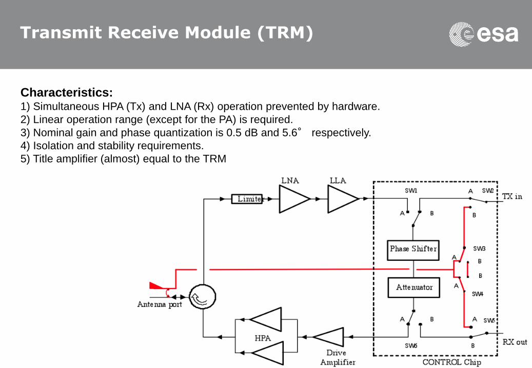
Internal Calibration (short term variations)
Goal and purpose
1) To track the fine variations of the transmitter power times the receiver gain product, PG,
during a data take.
2) Subsequent in the ground processing the complex PG will be applied for image correction.
Calibration requirements/justification
1) All nominal paths of the transmitted signal and of the received echoes shall be covered by internal
calibration signals.
2) High stability of non-nominal paths used by calibration signals.
3) Uniform illumination is used as baseline during Internal Calibration in place of the Tx and Rx
beams, as the phase alignment due to external free space propagation towards the swath
and correspondingly in the antenna on receive is not needed.
Purpose of PCC2
1) To suppress leakage between Tx paths and Rx paths.
TRM (EFE) limitations
1) Simultaneous Tx and Rx operation prevented by hardware for any given TRM.
2) Linear operation range (except for the PA) is required.
3) Nominal gain and phase quantization is 0.5 dB and 5.6° respectively.

We care for a safer world
Internal Calibration (short term variations)
Calibration for Tx H-pol
9 PRIs for cal
11 measurements
Calibration for Tx V-pol
9 PRIs for cal
11 measurements
Cal signals, Paths and PCC commanding

We care for a safer world
Internal Calibration (short term variations)

We care for a safer world
In-orbit External Calibration

We care for a safer world
Sentinel-1 Transponder
– Main function of the transponder is to act as a very stable
target with a sufficiently large RCS
– The transponder will also function as a receiver for the azimuth
antenna pattern. The azimuth pattern receiver mode involves
detection and measurement of the amplitudes of received SAR
pulses. This mode will confirm the expected azimuth beam
pattern for the C-SAR phased array. Pointing can be derived
using an azimuth notch pattern on transmit.

We care for a safer world
CSAR and Transponder RequirementsParameter CSAR Requirement Transponders Requirement
Maximum Point Target Radar Cross Section 75 dBm2 70 dBm2
Transmit polarisation CSAR
Receive polarisation Transponder
H or V H or V
Transmit polarisation Transponder
Receive polarisation CSAR
H and V Both H and V
H to V imbalance 15 degrees Amplitude < 0.05 dB; Phase < 5 deg
Radiometric accuracy 1.0 dB (3s) 0.1 dB (3s)
Radiometric stability 0.5 dB (3s) 0.1 dB (3s)
Time Delay Adjustable from 1.0 ms to 1000 ms in
increments of 0.01 ms
Accuracy of the antenna pattern estimation or
accuracy of the transponder receiver mode
0.1 dB within the swath
1.0 dB at -20 dB level with
respect to the
maximum
0.2 dB of absolute gain
0.05 dB in the main lobe of the received
azimuth pattern relative to the peak
value
0.5 dB at -20 dB level with respect to the
peak value of the main lobe of the
received azimuth pattern
Dynamic range of the receiver mode The dynamic range shall be sufficient to
reconstruct the azimuth pattern of
the Sentinel-1 SAR antenna down
to a side lobe level of – 40 dB.
Pixel localisation 2.5 - 10 m (3s) depending
on the mode
1 m (3s)

We care for a safer world
Transponder Architecture
– A single antenna for both reception and transmission
– A microwave transceiver to frequency shift signals
– Digital Signal Processor for the programmable delay on
the signal, to fine tune the gain to achieve a 76 dBm2
radar cross section (RCS), and to apply a transponder
compensation filter.
– Support subsystems
– a control and data storage computer;
– a GPS Clock for UTC synchronization;
– a Pan-Tilt unit for orienting the antenna
boresight towards the expected satellite
overpass location;
– support for external communications, enabling
full remote control and a data download
capacity;
– a power supply;
– an environment control system.
We care for a safer world
Transponder deployment
– Cross over region of beams in ascending and descending
swaths
– As many sub-swaths / beams as possible
– Three transponders close to ESTEC
– Easy deployment and maintenance

We care for a safer world
Selected Sites in The Netherlands
ESTEC
KNMI
(Royal
Netherlands
Meteorological
Institute)
NLR
(National
Aerospace
Laboratory)

We care for a safer world
Transponder measurements
E = ESTEC
K = KNMI
N = NLR
Orbit IW1 IW2 IW3 WV1 WV2 EW1 EW2 EW3 EW4 EW5 SM1 SM2 SM3 SM4 SM5 SM6 Cycles
D8 K EKN K E 4
A15 N E EK N E K N 6
D37 N E KN E K E 4
A88 E K K K N K N 5
D110 K E E KN E KN E 5
A117 N N 2
A161 EK E K E K 4
Total 3 3 3 2 2 6 3 2 4 2 3 2 3 2 3 2
9 4 17 15

We care for a safer world
Sentinel-1 radiometric accuracy
Requirement:
1dB radiometric accuracy (3σ) Mode
SM IW EW WV
Absolute radiometric accuracy,
co-polar (dB, 3σ) 0.75 0.77 0.90 0.92
Absolute radiometric accuracy,
cross-polar (dB, 3σ) 0.76 0.78 0.91 NA

We care for a safer world
Thank you for your attention
Simulated Sentinel-1 Mosaic based on ASAR