intermittent and continuous ATP 101119 - IRSE Nederland · An Introduction to Intermittent and...
53
An Introduction to Intermittent and Continuous ATP ir. WJ Coenraad FIRSE Version 2c dated February 13th, 2012
Transcript of intermittent and continuous ATP 101119 - IRSE Nederland · An Introduction to Intermittent and...
An Introduction to Intermittent and Continuous ATP
ir. WJ Coenraad FIRSE
Version 2c dated February 13th, 2012

IntroductionIn contrast to road traffic, where the driver of the individual vehicle has the
responsibility for guiding his car, rail traffic is externally controlled. This is true for the lateral guidance where the train has to follow the track forced by the rim or the wheels, and the longitudinal movement, where signals impose stopping points on the driver. A signalling system has to be used, as reaction on time is not possible when a driver sees an obstacle. In rail systems, braking distances are too long to rely on driver’s vigilance.
The very first task of railway signalling therefore was to install a signalling system, which gave the driver instruction if he could proceed or if he had to stop. With the driver obeying the instructions given by the signals, collisions of trains could be avoided.
A large history of railway accidents, proves that drivers do not always follow the instructions of the signalling system. To supervise the driver,” train stop” systems were introduced which caused an automatic brake application when the driver passed a signal at danger. (More information on “why ATP systems” are required is given in D. Fenner’s contribution to this course.)
In the early days of railway signalling, these train stop systems were mostly mechanical. Later on, as technology evolved, the physical principle of “informing the train it had SPADded” or “Track to Train Transmission” changed to permanent magnets and later on to transponders.
In the meantime, most of the mainline railways found that a simple train stop system at the signal at danger was not sufficient to avoid all accidents. Other systems, which warned the driver, or supervised train speed some distance before the signal at danger, were introduced. Excessive speed on certain sections of the line, for example at speed restrictions, caused accidents. Hence Automatic Train Protection (ATP) systems were also used to supervise the driver in these cases.
In the early days of ATP, most systems were intermittent in transmission and supervision. Information was only transmitted at specific points along the track. The information the supervision was based on and the length of the supervision was linked to the location of the transmission. A driver having acknowledged the warning or complied with the speed supervision could usually release the brakes or even accelerate subsequently.
More recent systems provide a continuous supervision of the train, although their transmission system is only intermittent. The driver is not allowed to exceed a speed profile / braking curve, which is based upon the data transmitted from a first transponder, until the train gets new information from the next transponder and the supervised speed profile is updated accordingly. These systems certainly increase the safety of operation considerably; on the other hand they also can restrict the throughput of the line.
Where track circuits were available, or other means such as radio, ATP systems using semi-continuous track to train transmission could be implemented. These can provide an almost instantaneous update to the train of changes to the signal aspect or line conditions ahead. The supervised speed profile is then also updated instantaneously, e.g. on approaching a signal clearing ahead of the train, and therefore the ATP impact on line capacity can be limited. Furthermore, on a system

2
level the degree of safety is also higher, as for example emergency stop information can be transmitted with negligible delay.
All systems described derive their information from the line side signalling system and in almost all systems the commands transmitted to the driver have to be identical to or more restrictive than those given by the line side signals. Especially for high density traffic, the existing block system on railway lines is not always adequate and some form of enhanced, or even moving, block can be introduced to further enhance capacity utilisation. In these cases, ATP/ATC partially or totally replaces line side signals with in-cab signalling and has to have priority over the lateral signalling system. Thus modern ATP/ATC systems can offer operational advantages over conventional signalling systems and at the same time can reduce cost.
This paper discusses what now should be called traditional or conventional ATP and ATC systems and ERTMS/ETCS. With the exception of a brief mention of ERTMS/ETCS level 3, it does not discuss transmission based or communications based signalling systems.
3
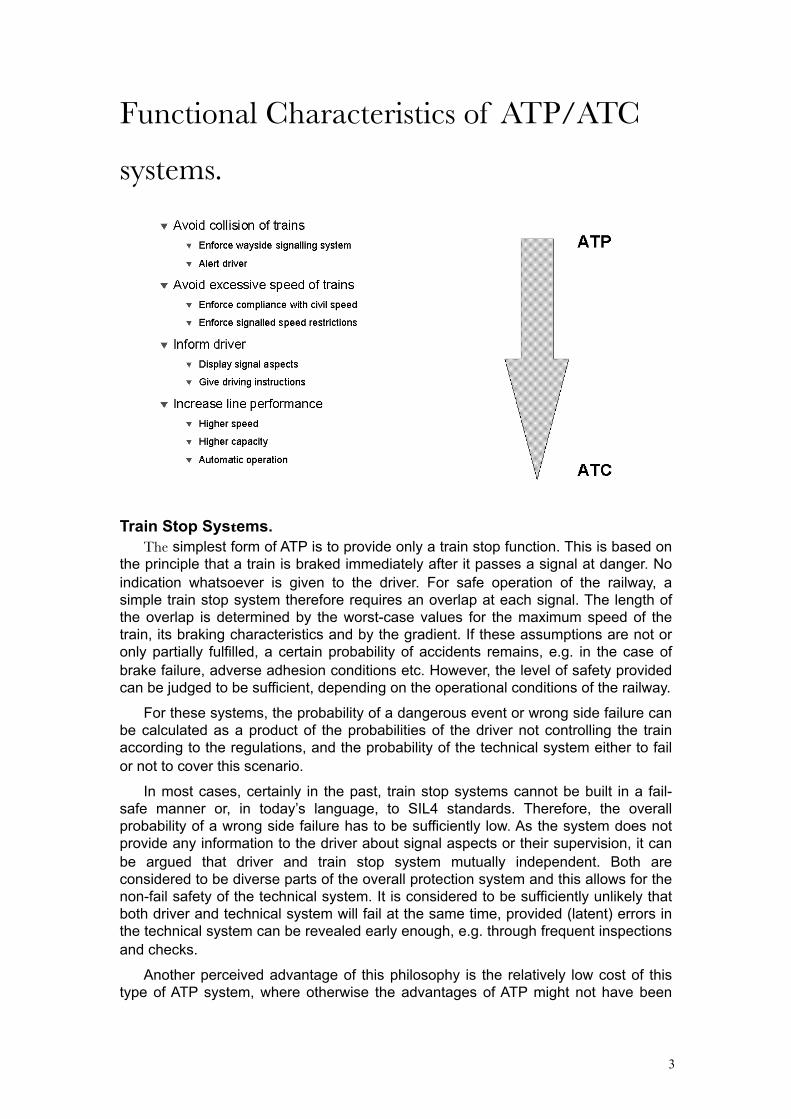
Functional Characteristics of ATP/ATC
systems.
Train Stop Systems.The simplest form of ATP is to provide only a train stop function. This is based on
the principle that a train is braked immediately after it passes a signal at danger. No indication whatsoever is given to the driver. For safe operation of the railway, a simple train stop system therefore requires an overlap at each signal. The length of the overlap is determined by the worst-case values for the maximum speed of the train, its braking characteristics and by the gradient. If these assumptions are not or only partially fulfilled, a certain probability of accidents remains, e.g. in the case of brake failure, adverse adhesion conditions etc. However, the level of safety provided can be judged to be sufficient, depending on the operational conditions of the railway.
For these systems, the probability of a dangerous event or wrong side failure can be calculated as a product of the probabilities of the driver not controlling the train according to the regulations, and the probability of the technical system either to fail or not to cover this scenario.
In most cases, certainly in the past, train stop systems cannot be built in a fail-safe manner or, in today’s language, to SIL4 standards. Therefore, the overall probability of a wrong side failure has to be sufficiently low. As the system does not provide any information to the driver about signal aspects or their supervision, it can be argued that driver and train stop system mutually independent. Both are considered to be diverse parts of the overall protection system and this allows for the non-fail safety of the technical system. It is considered to be sufficiently unlikely that both driver and technical system will fail at the same time, provided (latent) errors in the technical system can be revealed early enough, e.g. through frequent inspections and checks.
Another perceived advantage of this philosophy is the relatively low cost of this type of ATP system, where otherwise the advantages of ATP might not have been

4
affordable at all. In literature, e.g. [26] SIL levels specified for intermittent systems are quoted as SIL 2.
Intermittent Systems.Intermittent systems resemble train stop systems to the extent that information is
only passed “intermittently” from track to train at certain fixed locations. Most systems of earlier design can therefore only provide intermittent supervision as well, e.g. between distant and main signals and thus will only provide protection against a signal being passed at danger. However as technology evolved they became more capable and nowadays most modern systems are able to provide continuous supervision / protection of the train and can even offer (continuous) speed supervision.
Simple ATP systems such as the German INDUSI, or AWS and TPWS in the UK operate in background mode and no indication is given to the driver, except perhaps on system health or when an emergency brake application has occurred. The driver has to observe the line side signals and react according to their aspects. Only in the case of a driver driving too fast or SPADding will the system automatically apply the emergency brake. The same safety design philosophy as mentioned above for the train stop system are applicable.
More sophisticated intermittent ATP systems, for example the British ATP systems, Dutch ATB NG, Ebicab, or indeed ERTMS/ETCS level 1, are also based on principle that the driver is still primarily responsible for observing signals and operating the train. The ATP still acts as a safety net. However, as newer technology allows more information to be transmitted, some indications can be given to the driver, for example target speed and the distance to go, i.e. to the point at which the train’s speed must be under the new target speed limit, or the distance to the signal at danger. As wrong indications could mislead the driver and so provoke unsafe reactions, the system, or at the very minimum its speed supervision sub-system, has to be fail-safe in this respect. Data generation, data transmission and data evaluation on board have to have a high level of safety integrity as well, as a failure could cause a dangerous situation with a driver relying on the cab display rather than on the line side signals.
In general the in-can signalling allows the driver to optimise his driving and certainly provides a level of “comfort”, e.g. when driving in adverse weather conditions affecting visibility of signals.
Continuous SystemsContinuous ATP/ATC systems normally provide full cab signalling, which implies
that the driver must be able to fully rely on the safety of the system. There are two principles in use, which differ in safety philosophy. In France, the TVM system has a vital display to the driver, the driver himself is considered fail-safe, therefore there are less technical safety requirements on the implementation of the speed supervision and emergency brake application functions. In contrary, among others, the Dutch ATB and German LZB employ a non-vital cab display but implement a vital speed supervision and access to the emergency brake. In this philosophy the driver is considered a non-vital part of the overall train control system and even if he were misled by the cab signal, the speed supervision and brake application will intervene in a fail-safe manner.

5
Continuous system (Dutch ATB)
In continuous ATP/ATC systems of modern design, there is sufficient information available to feed the Automatic Train Operation (ATO) equipment as well. In case of automatic driving, ATP/ATC speed supervision and the emergency brake application has to be implemented as a vital system, as usually the ATO equipment is not fail-safe. Especially in automatic or even more so in driverless systems, the ATP/ATC system has to take full responsibility for the safe movement of the train. Therefore, a high level of integrity is required for the system.
Capacity Considerations.
A Railway’s safety philosophy is an essential factor when selecting an ATP/ATC system. Another important issue is the effect of the train control system on line throughput and network capacity.
Even assuming the existence of a well designed signal system, with signal spacing appropriate for line speed etc. the introduction of an ATP system usually requires headways to be increased, whilst still maintaining overlaps. This apparent
6
contradiction stems from the fact that where previously an ideal driver may have been assumed in signal layouts, the introduction of ATP usually is the consequence of a more explicit risk evaluation concerning train and driver failure modes, combined with the requirement to prevent these risks causing accidents to a much higher degree of certainty. Secondly of course the introduction of technical systems will always introduce trade-offs between response times, availability, delays caused by spurious or erroneous interventions etc. Technology will almost always be less adaptive and flexible, especially in the case of vital systems, and limit the human operator’s degrees of freedom. On top of that, in the design, as in any technical system, (safety)margins are introduced and enforced.
ATP enforces line speeds and in most modern systems supervises brake curves. That limits a driver’s ability to make up time.
Defensive driving techniques (with or without ATP) involve. not entering the platform at maximum speed and coming to a stop within 1 m of the overlap or departure signal with screeching brakes etc. ATP enforces this.
Rolling stock engineers asked to specify guaranteed brake performance of their trains “to SIL 4 requirements” will incorporate their own safety margins. Engineers devising slip/slide algorithms required in position determination as part of brake curve supervision, will try to err on the safe side etc.
In this chapter we examine the capacity effects and a number of strategies to mitigate them or even improve line capacity using ATP/ATC systems. In practice their efficiency would depend on the proportion of the rolling stock being equipped with the required ATP/ATC capabilities.
Intermittent SystemsIn very simple intermittent ATP systems such as AWS or Indusi, the train-stop
system only applies the emergency brake when the driver does not acknowledge a warning or passes a signal at danger. Therefore an overlap is required to allow a train to be stopped within the distance to the danger point that is being protected by that signal. In most of those systems a (standard) overlap is used, which for example is nominally 200 yards in the BR system. This overlap reduces line capacity, although of course that overlap would also have to be required and perhaps even have to be longer, on a non-ATP railway.
In German signalling systems, the overlap is only protected when the train is approaching the signal and is still at a considerable distance. Depending on time elapsed or position of the approaching train, the overlap can subsequently be released. This certainly improves the headway of trains, but on the other hand it increases the danger of an accident when the overlap has been released and the train is erroneously accelerating again.
Brake Supervision And Release SpeedIn ATP systems that check if the brakes are applied after receiving a “caution” or
“prepare to stop” type of command from the trackside, the driver can no longer immediately react on an improvement of the signal aspect and release the brake or accelerate as he would have been able to do in the absence of ATP. To compensate for this some systems allow the driver to override, or release, this brake supervision after observing the signal aspect ahead improving. This of course has to be weighed against the risk of errors of perception etc as this override can easily become a reflex due to its repetitive nature especially on densely trafficked lines.
If supervision of braking curves is implemented, the brake can be released either when the speed is below a predefined value, or the driver has taken special a action,
7
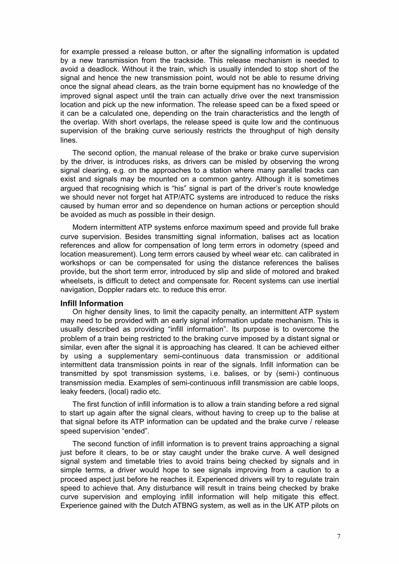
for example pressed a release button, or after the signalling information is updated by a new transmission from the trackside. This release mechanism is needed to avoid a deadlock. Without it the train, which is usually intended to stop short of the signal and hence the new transmission point, would not be able to resume driving once the signal ahead clears, as the train borne equipment has no knowledge of the improved signal aspect until the train can actually drive over the next transmission location and pick up the new information. The release speed can be a fixed speed or it can be a calculated one, depending on the train characteristics and the length of the overlap. With short overlaps, the release speed is quite low and the continuous supervision of the braking curve seriously restricts the throughput of high density lines.
The second option, the manual release of the brake or brake curve supervision by the driver, is introduces risks, as drivers can be misled by observing the wrong signal clearing, e.g. on the approaches to a station where many parallel tracks can exist and signals may be mounted on a common gantry. Although it is sometimes argued that recognising which is “his” signal is part of the driver’s route knowledge we should never not forget hat ATP/ATC systems are introduced to reduce the risks caused by human error and so dependence on human actions or perception should be avoided as much as possible in their design.
Modern intermittent ATP systems enforce maximum speed and provide full brake curve supervision. Besides transmitting signal information, balises act as location references and allow for compensation of long term errors in odometry (speed and location measurement). Long term errors caused by wheel wear etc. can calibrated in workshops or can be compensated for using the distance references the balises provide, but the short term error, introduced by slip and slide of motored and braked wheelsets, is difficult to detect and compensate for. Recent systems can use inertial navigation, Doppler radars etc. to reduce this error.
Infill InformationOn higher density lines, to limit the capacity penalty, an intermittent ATP system
may need to be provided with an early signal information update mechanism. This is usually described as providing “infill information”. Its purpose is to overcome the problem of a train being restricted to the braking curve imposed by a distant signal or similar, even after the signal it is approaching has cleared. It can be achieved either by using a supplementary semi-continuous data transmission or additional intermittent data transmission points in rear of the signals. Infill information can be transmitted by spot transmission systems, i.e. balises, or by (semi-) continuous transmission media. Examples of semi-continuous infill transmission are cable loops, leaky feeders, (local) radio etc.
The first function of infill information is to allow a train standing before a red signal to start up again after the signal clears, without having to creep up to the balise at that signal before its ATP information can be updated and the brake curve / release speed supervision “ended”.
The second function of infill information is to prevent trains approaching a signal just before it clears, to be or stay caught under the brake curve. A well designed signal system and timetable tries to avoid trains being checked by signals and in simple terms, a driver would hope to see signals improving from a caution to a proceed aspect just before he reaches it. Experienced drivers will try to regulate train speed to achieve that. Any disturbance will result in trains being checked by brake curve supervision and employing infill information will help mitigate this effect. Experience gained with the Dutch ATBNG system, as well as in the UK ATP pilots on

8
GWML en Chiltern lines indicate that infill information will be required at around 65% of the equipped signals. Where and over which length infill information should be available varies with traffic patterns and is timetable dependent. This is especially true if infill balises are used. Usually infill information over distances of 300 – 500 m is sufficient.
Continuous SystemsThe obvious benefit of continuous ATP/ATC systems is that they can be thought
of as continuously providing infill information. They offer a way to implement ATP / ATC on a well designed railway whilst minimising capacity sacrifices. An added benefit is that they also provide a means of informing a train driver of a signal reversion or revocation.
Continuous systems largely reduce the ATP/ATC capacity penalties, and in some cases they even can improve headways. This is mainly due to the quasi instantaneous update of signal aspects information and speed/brake curves to be supervised they offer.
Examples where the introduction of continuous ATP / ATC systems has had a positive effect on capacity, are usually related to retrofitting existing lines, where signal layout etc. is sub optimal for modern rolling stock. On some German lines for example, special train categories are allowed to run at higher speeds than allowed by the original distance between distant and main signals. In this mode of operation, these trains equipped with “better braking”, when running under full LZB supervision, the in-cab signalling takes precedence over the line side signals.
Raising Line SpeedIn most cases raising maximum line speed involves introducing multi-aspect
signalling, increasing block length and / or increasing the distance between distant and main signals. If it can be shown that modern rolling stock, e.g. through additional track brakes, has a guaranteed brake performance for those higher speeds still commensurate with the existing signal spacing, that cost can be avoided. Trains equipped with a continuous ATP / ATC system, usually employing in cab signalling and full speed and brake curve supervision can then be allowed to travel at the higher maximum speed under the supervision of such systems.
Examples of this strategy can be found in Germany where line speeds were raised to 200 km/h for certain train classes when they are under full LZB supervision. In that case the in-cab signal takes precedence over the lineside signals.
In a similar manner, in-cab signals can be used to provide a longer “electrical sight” and maximum speeds can be raised without requiring multi-aspect block signals to be installed.
Both strategies can also be implemented using an ERTMS level 2 system.
It has to be noted that some railway administrations / safety authorities do not approve of the use of in-cab signals taking precedence over lineside signals, as it involves different interpretations of signal aspects depending on train type. The obvious hazard is that a driver would mistakenly assume the higher line speed was allowed on a non-equipped train.
Increasing Block DensityThe advantages of “mixed-signalling” systems can be taken even further if we
want to increase line capacity by sub dividing blocks on a line to reduce headways, either because the original block length was too long for the required line speed and
9
traffic demand has increased, or as before, if rolling stock development has delivered better braking capabilities.
In a conventional ATP / ATC systems this still involves installing additional train detection equipment in the subdivided blocks. In ERTMS level 2 (and similar systems) instead of erecting real signals, we can now use “virtual signals” at the (new) block boundaries. These block boundaries are usually marked by a balise and a sign and the virtual signals show their aspects, or rather imdicate their movement authorities through the in-cab signal.
In ERTMS level 3, if and when that implementation of the moving block principle becomes available, it might even be possible to dispense with the additional balises and / or leave out the additional train detection equipment. Examples of this can be found in Germany on the so called “Neubaustecken” implementing a concept known as CIR-ELKE.
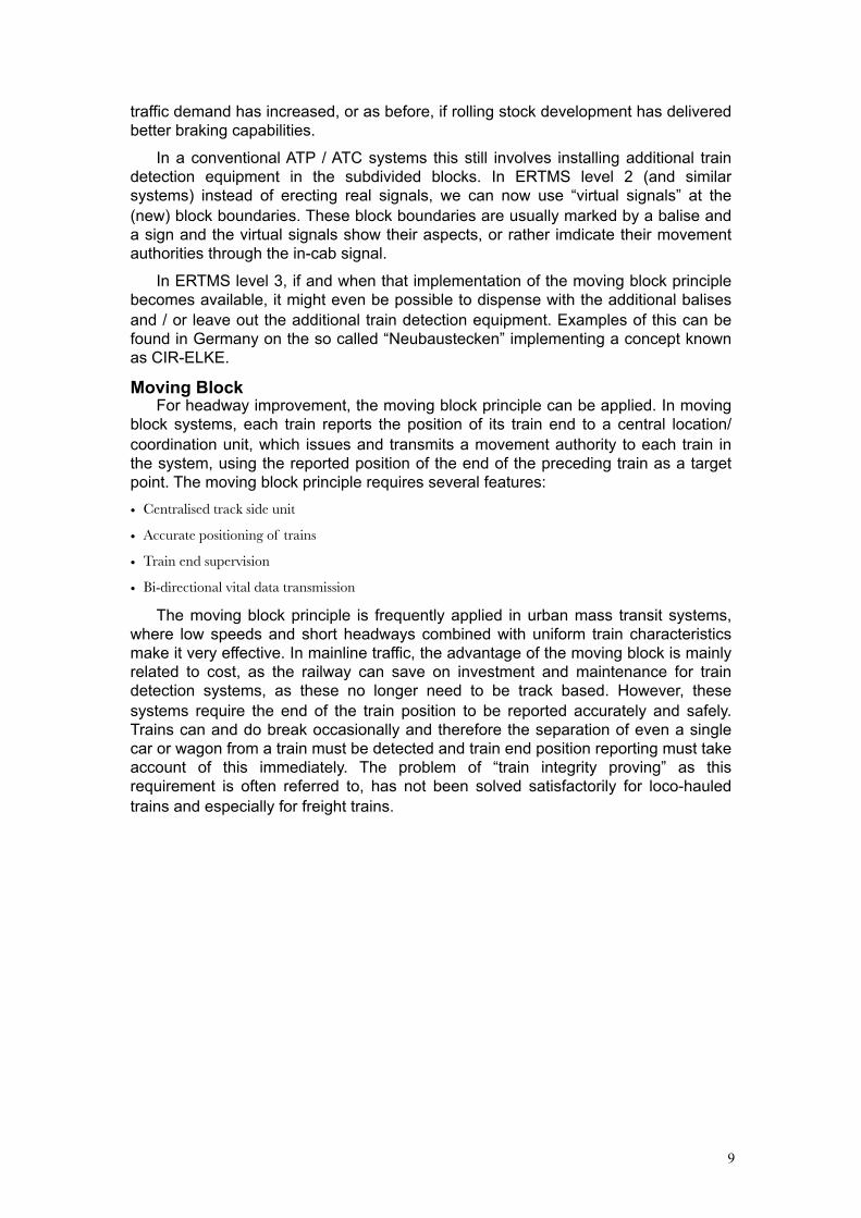
Moving BlockFor headway improvement, the moving block principle can be applied. In moving
block systems, each train reports the position of its train end to a central location/ coordination unit, which issues and transmits a movement authority to each train in the system, using the reported position of the end of the preceding train as a target point. The moving block principle requires several features:
• Centralised track side unit
• Accurate positioning of trains
• Train end supervision
• Bi-directional vital data transmission
The moving block principle is frequently applied in urban mass transit systems, where low speeds and short headways combined with uniform train characteristics make it very effective. In mainline traffic, the advantage of the moving block is mainly related to cost, as the railway can save on investment and maintenance for train detection systems, as these no longer need to be track based. However, these systems require the end of the train position to be reported accurately and safely. Trains can and do break occasionally and therefore the separation of even a single car or wagon from a train must be detected and train end position reporting must take account of this immediately. The problem of “train integrity proving” as this requirement is often referred to, has not been solved satisfactorily for loco-hauled trains and especially for freight trains.
10
Technology of ATP/ATC systemsThis chapter illustrates the principles of the design of the main classes of ATP
system, without claiming to be exhaustive. Although we begin our journey with the oldest and simplest systems and their technology may appear to obsolete, many of these are still in existence today. In part this is due to the fact that any ATP implementation requires substantial investments in both infrastructure and the fleet. Once selected, any given implementation of an ATP/ATC systems tends to lock the railway into the associated operational principles, rules and regulations. On top of that, technology choices for ATP/ATC, such as a type carrier and modulation for the track to train transmission create a mutual dependency with the equipment, e.g. a coded track circuit or radio bearer service, a set of mutually dependent EMC/EMI limits etc. If not mandated by law, the business case for ATP/ATC is difficult to make, as shown in the UK with the ERTMS/ETCS business case and the business case for migration from a given system, generation or technology to another is even worse.
In the field of course, many permutations of the implementations described exist.
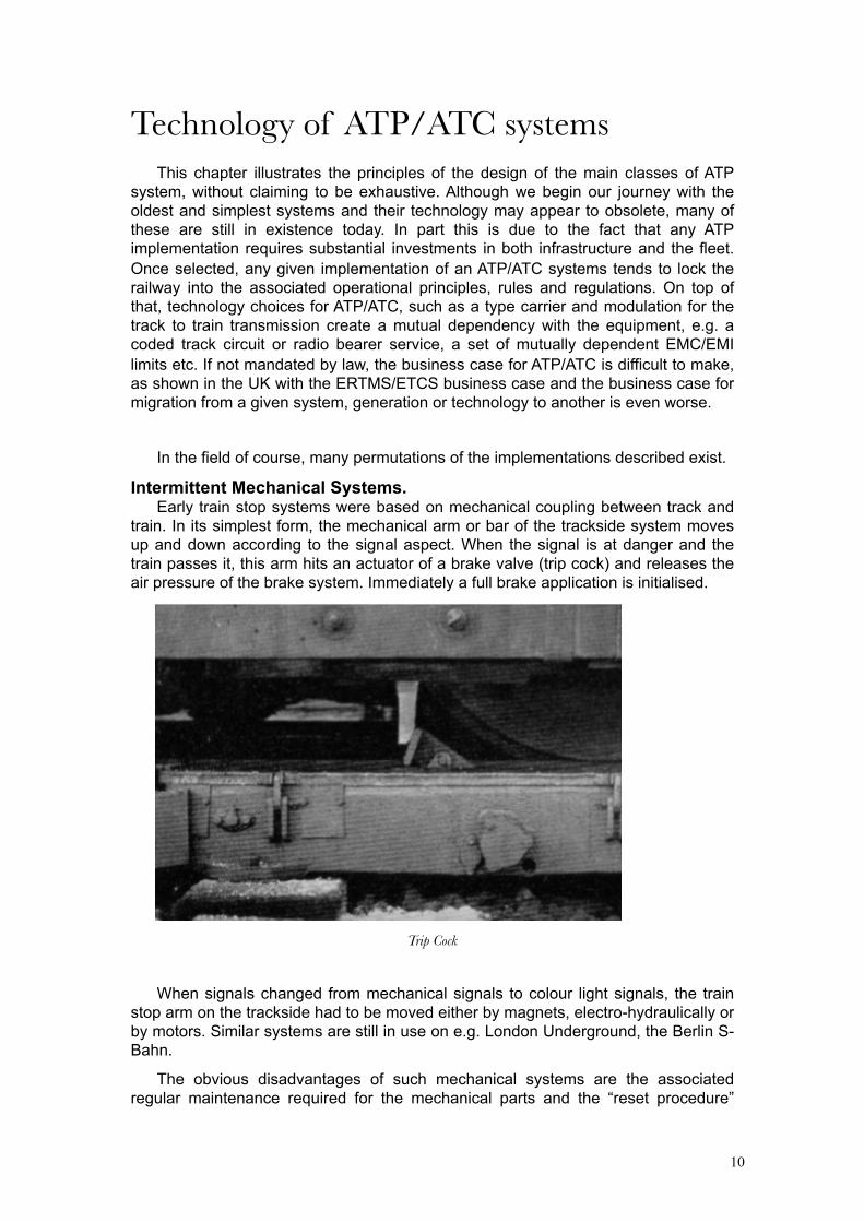
Intermittent Mechanical Systems.Early train stop systems were based on mechanical coupling between track and
train. In its simplest form, the mechanical arm or bar of the trackside system moves up and down according to the signal aspect. When the signal is at danger and the train passes it, this arm hits an actuator of a brake valve (trip cock) and releases the air pressure of the brake system. Immediately a full brake application is initialised.
Trip Cock
When signals changed from mechanical signals to colour light signals, the train stop arm on the trackside had to be moved either by magnets, electro-hydraulically or by motors. Similar systems are still in use on e.g. London Underground, the Berlin S-Bahn.
The obvious disadvantages of such mechanical systems are the associated regular maintenance required for the mechanical parts and the “reset procedure”
11
after a trip cock has been tripped, which not only is time consuming, but requires the driver to leave his cab and walk along the track which immediately exposes him to significant health and safety risks, not the least of which is being hit by another train.
Whilst such systems are generally regarded as fail-safe by the inherent mechanical properties of the design and equipment, reports of wrong side failures exist, demonstrating that these systems, as virtually all signaling systems, depend on regular (preventative) maintenance and inspections to maintain their safety levels.
Intermittent Contactless SystemsPermanent Magnet Systems.
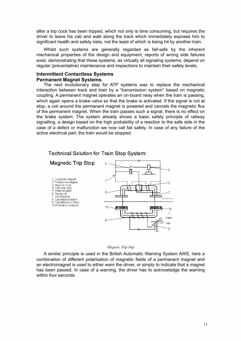
The next evolutionary step for ATP systems was to replace the mechanical interaction between track and train by a “transmission system” based on magnetic coupling. A permanent magnet operates an on-board relay when the train is passing, which again opens a brake valve so that the brake is activated. If the signal is not at stop, a coil around the permanent magnet is powered and cancels the magnetic flux of the permanent magnet. When the train passes such a signal, there is no effect on the brake system. The system already shows a basic safety principle of railway signalling, a design based on the high probability of a reaction to the safe side in the case of a defect or malfunction we now call fail safety. In case of any failure of the active electrical part, the train would be stopped.
Magnetic Trip Stop
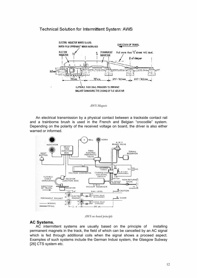
A similar principle is used in the British Automatic Warning System AWS, here a combination of different polarisation of magnetic fields of a permanent magnet and an electromagnet is used to either warn the driver, or simply to indicate that a magnet has been passed. In case of a warning, the driver has to acknowledge the warning within four seconds.
12
AWS Magnets
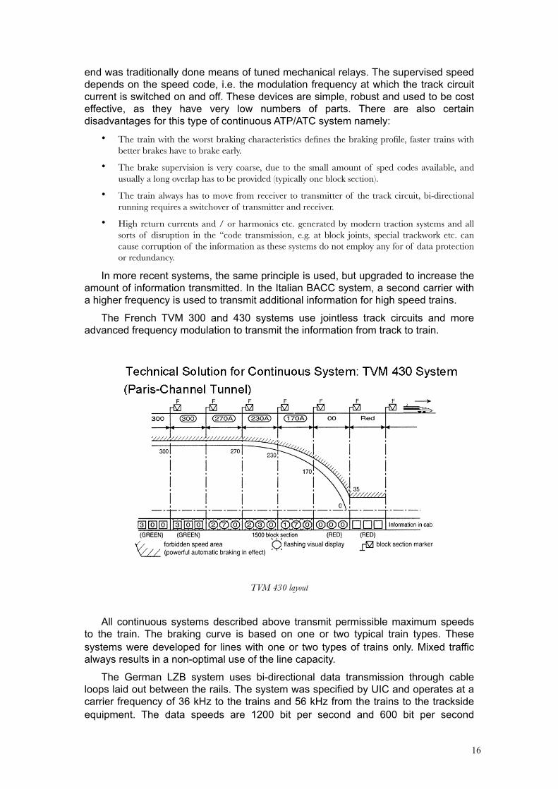
An electrical transmission by a physical contact between a trackside contact rail and a trainborne brush is used in the French and Belgian “crocodile” system. Depending on the polarity of the received voltage on board, the driver is also either warned or informed.
AWS on-board principle
AC Systems.AC intermittent systems are usually based on the principle of installing
permanent magnets in the track, the field of which can be cancelled by an AC signal which is fed through additional coils when the signal shows a proceed aspect. Examples of such systems include the German Indusi system, the Glasgow Subway [26] CTS system etc.

13
The German INDUSI system uses tuned circuits trackside and on board. The circuits are tuned to the same frequency and are detuned when a close coupling between both circuits takes place. The on-board resonant circuit is a serial resonant circuit and is fed by an oscillator with its natural resonant frequency. A high oscillator current is therefore obtained. The oscillator current is monitored by the train borne equipment of INDUSI. When the train passes a trackside resonant circuit (still referred to as a magnet!), the coupling detunes the train borne equipment and the oscillator current decreases. The oscillator current is compared to a threshold and when the current falls under this threshold, a reaction is triggered. To cancel the operation of the trackside resonant circuit in case of a go-aspect, the capacitor on the trackside circuit is shorted by the signalling equipment and the train resonant circuit is only slightly damped when passing the signal, the threshold would not be touched.
Indusi Coils
In the INDUSI system, 500 hertz, 1000 hertz and 2000 hertz circuits are used. The 2000 hertz magnet is placed at a main signal, the 1000 hertz magnet is at a distant signal and the 500 hertz magnet at a distance of 450 meters before the point of danger, which in general is at the end of the overlap.

14
Positioning of Indusi magnets
In the traditional INDUSI system, supervision was based on speed supervision when passing the magnets or fixed times after that occurrence. In the newer train born equipment which is based on micro-processor technology, a continuous supervision of braking curves which is triggered when passing a magnet is performed by the software logic.
Transmission Based Intermittent Systems.
A common feature of the intermittent systems described previously is their rather limited “data transmission capacity”, usually equivalent to 1 bit of information (signal on or off).
Modern intermittent systems are based on transmission of data-telegrams to trains. These telegrams are always secured by a safety code, so that sporadic interference cannot cause an undetected corruption of the message. Existing systems are either based on transponders with a contact length for data transmission of less than 1 meter or on loops which can have lengths of up to a few hundred meters.
A typical representative of the transponder solution is the KVB system used by SNCF, which in turn was derived from the Swedish Ebicab system. A minimum of two transponders is laid out in the middle between the two rails. The duplication of the transponders primarily guarantees the safety of the system and also enables a logical detection of travel direction. The locomotive is emitting pulses of 27 MHz carrier frequency at a repetition rate of 50 kHz. The trackside transponder transforms these pulses to a frequency of 4.5 MHz and reflects them to the locomotive. The shape of the amplitude of the reflected signal indicates if a logical one or a logical zero is transmitted. This system needs no trackside power supply for the transmission itself and hence no cabling if the information in the transponder or balise is fixed. Active transponders and/or transponders transmitting variable data obviously do need to be cabled.
A further development of the transmission principle of Ebicab and KVB is applied in the ERTMS/ETCS Eurobalise.

15
Transponder systems can be active or passive, the latter employing remote powering of the transponder by the vehicle. Transponders can also be fixed in their message content, or contain switcheable messages that can be selected through a connection to a signal, interlocking etc. Transponders that are both passive and fixed have the advantage of requiring no trackside cabling at all. Selectivity of a balise’s message to the direction of travel of a train can be achieved physically, e.g. by offsetting them from the centre of the rails, or through coding of messages in two or more balises in a group etc. The latter is also used to extend the amount of data that can be transmitted. Balise messages can contain pointers, identifying the next balise a train should encounter, depending on its route if needed, to ensure an alarm can be raised if the next balise is missed, misread or simply absent.
Loop systems always are active, that means that they require a trackside power feed.
The system installed in the Netherlands as ATBNG, Belgium (TBL) and the UK on the GWML is the TBL system, which uses a combination of an active transponders and loops. Both parts are fed with the identical information, but at different transmission speeds. The transponder transmits at a bit rate of 25 kbit per second, the loop with approximately 1 kbit per second. Transponder and loop are transmitting at a carrier frequency of 100 kHz. In this system transponders are located at signals, whereas the loops are used to transmit semi-continuous “infill” information in rear of a signal where needed. The function of the infill information is to allow a speed supervision curve to be updated as soon as a signal aspect improves, rather than forcing the train to continue braking until it reaches the transponders at the location of the next signal.
The SELCAB system is based on loop transmission only. It will be described in more detail later on.
Future intermittent systems could possibly be based on microwave transmission. One example is the AMTECH system, which was standardised by UIC for wagon identification application (AVI). This system could be used in a reverse manner, that means the transponder is mounted on trackside and the reader on train-borne for an intermittent data transmission system. This AMTECH transponder is based on the backscatter principle and is operating at a frequency of 2.4 to 2.5 GHz. The transmission speed is in the range of 150 kbit per second. The microwave technology equipment is small in size and low in cost, but is sensitive to transmission problems when debris, salt water etc. is present in the transmission path. Although it was considered to be a promising technology especially where fixed information has to be transmitted, these transmission problems prevented its selection as the transmission medium for Eurobalise. At present, the application of this system as transponder is limited to Metros (London and Madrid).
Continuous Systems.The traditional method for data transmission in continuous systems is to use
coded track circuits. In the first incarnations of this family of ATP systems the conventional low frequency track circuits used throughout the world are used as the carrier for track to train transmission. The detection current flowing through the rails as soon as a section is occupied, is used as the carrier for the ATP/ATC codes and is “amplitude modulated” by periodically switching it on and off with a frequency of a few Hertz, indicating the speed code. The carrier frequency itself can be 50 or 60 Hz depending on the mains frequency of the country, or 75 Hz as in the Dutch first generation ATB system, chosen to avoid interference from the public grid. The encoding of the speed codes on trackside and decoding on the trainborne reception
16
end was traditionally done means of tuned mechanical relays. The supervised speed depends on the speed code, i.e. the modulation frequency at which the track circuit current is switched on and off. These devices are simple, robust and used to be cost effective, as they have very low numbers of parts. There are also certain disadvantages for this type of continuous ATP/ATC system namely:
• The train with the worst braking characteristics defines the braking profile, faster trains with better brakes have to brake early.
• The brake supervision is very coarse, due to the small amount of sped codes available, and usually a long overlap has to be provided (typically one block section).
• The train always has to move from receiver to transmitter of the track circuit, bi-directional running requires a switchover of transmitter and receiver.
• High return currents and / or harmonics etc. generated by modern traction systems and all sorts of disruption in the “code transmission, e.g. at block joints, special trackwork etc. can cause corruption of the information as these systems do not employ any for of data protection or redundancy.
In more recent systems, the same principle is used, but upgraded to increase the amount of information transmitted. In the Italian BACC system, a second carrier with a higher frequency is used to transmit additional information for high speed trains.
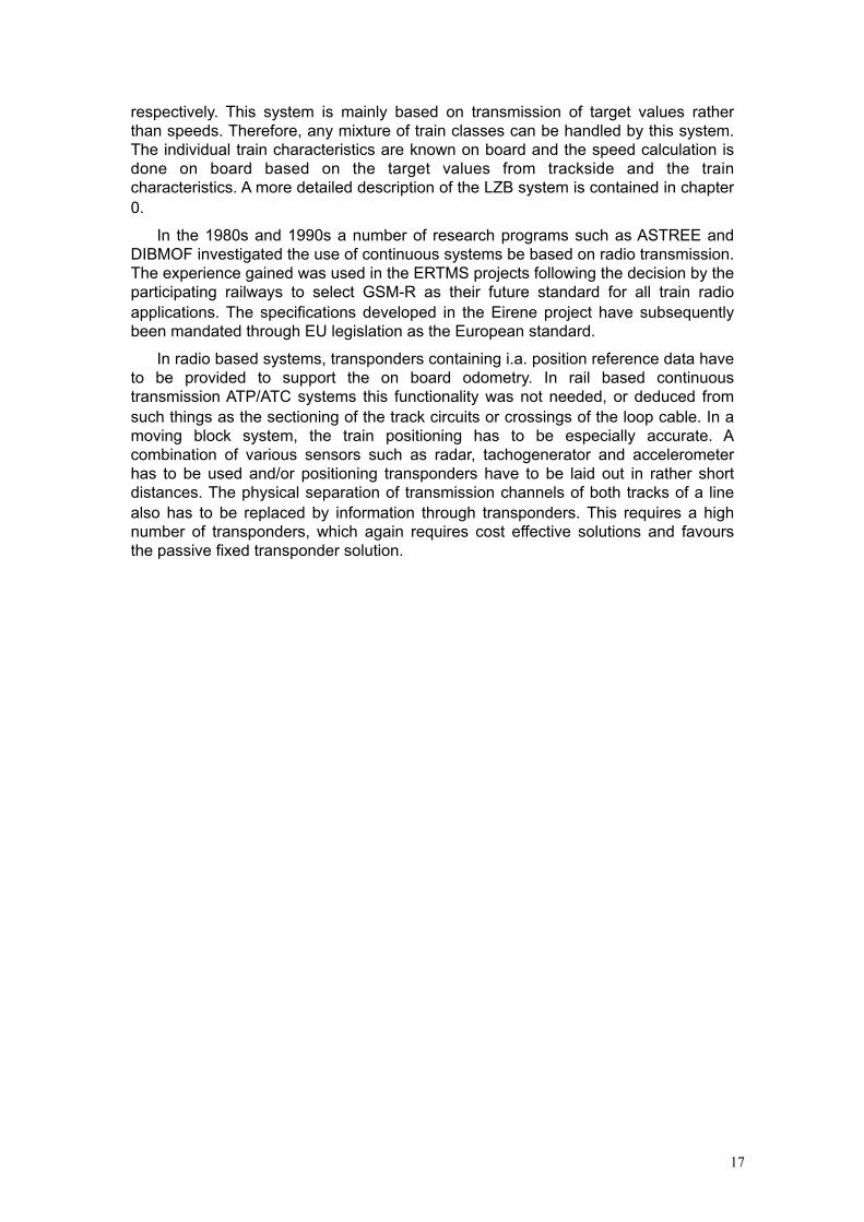
The French TVM 300 and 430 systems use jointless track circuits and more advanced frequency modulation to transmit the information from track to train.
TVM 430 layout
All continuous systems described above transmit permissible maximum speeds to the train. The braking curve is based on one or two typical train types. These systems were developed for lines with one or two types of trains only. Mixed traffic always results in a non-optimal use of the line capacity.
The German LZB system uses bi-directional data transmission through cable loops laid out between the rails. The system was specified by UIC and operates at a carrier frequency of 36 kHz to the trains and 56 kHz from the trains to the trackside equipment. The data speeds are 1200 bit per second and 600 bit per second
17
respectively. This system is mainly based on transmission of target values rather than speeds. Therefore, any mixture of train classes can be handled by this system. The individual train characteristics are known on board and the speed calculation is done on board based on the target values from trackside and the train characteristics. A more detailed description of the LZB system is contained in chapter 0.
In the 1980s and 1990s a number of research programs such as ASTREE and DIBMOF investigated the use of continuous systems be based on radio transmission. The experience gained was used in the ERTMS projects following the decision by the participating railways to select GSM-R as their future standard for all train radio applications. The specifications developed in the Eirene project have subsequently been mandated through EU legislation as the European standard.
In radio based systems, transponders containing i.a. position reference data have to be provided to support the on board odometry. In rail based continuous transmission ATP/ATC systems this functionality was not needed, or deduced from such things as the sectioning of the track circuits or crossings of the loop cable. In a moving block system, the train positioning has to be especially accurate. A combination of various sensors such as radar, tachogenerator and accelerometer has to be used and/or positioning transponders have to be laid out in rather short distances. The physical separation of transmission channels of both tracks of a line also has to be replaced by information through transponders. This requires a high number of transponders, which again requires cost effective solutions and favours the passive fixed transponder solution.
18
Train-borne System Architecture and
InterfacesThis chapter reuses text taken from the IRSE Competence Guidance for Train-borne
Train Control Systems , IRSE, 2009 [26]
Although there are many different types of train control systems that make use of train- borne subsystems, their system architectures tend to be broadly similar in terms of the main components and interfaces. This is not true, however, of simpler systems that provide only basic “stop” and/or “warning” functionality such as the TPWS/AWS systems in Great Britain. Unlike the more complex systems, these simpler systems vary considerably in terms of functionality, architectures and technology.
The remainder of this section focuses mainly on the more complex types of systems, ie. those that include ATP (and in some cases ATO) functionality, although some of the observations made are also true of the simpler software-based systems.
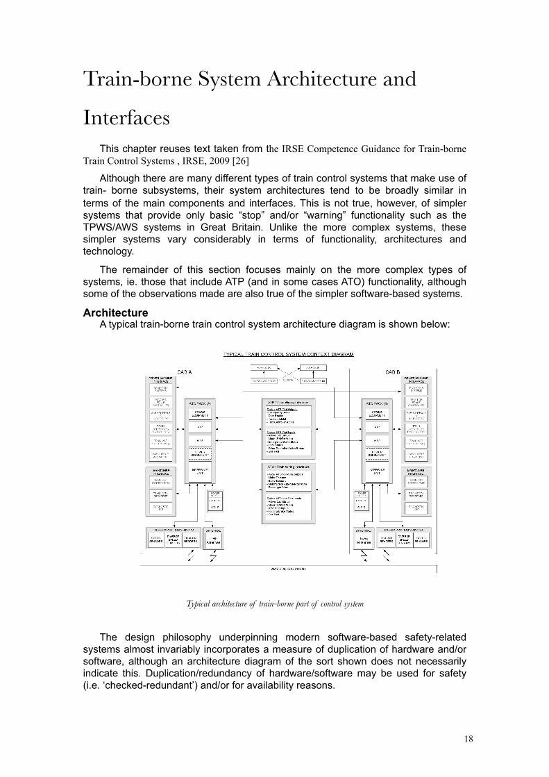
ArchitectureA typical train-borne train control system architecture diagram is shown below:
Typical architecture of train-borne part of control system
The design philosophy underpinning modern software-based safety-related systems almost invariably incorporates a measure of duplication of hardware and/or software, although an architecture diagram of the sort shown does not necessarily indicate this. Duplication/redundancy of hardware/software may be used for safety (i.e. ‘checked-redundant’) and/or for availability reasons.
19
The means by which duplication/redundancy is used to deliver safety and availability is a significant differentiator between various systems. It is important that this facet of the specific system under consideration is understood, as it has a significant bearing on both the application design and maintenance stages of the life-cycle.
For example, the safety architecture may be based on a single/mono-processor design or on a ‘checked-redundant’ two-out-of-two (2oo2) design. Availability may be achieved using a cold/warm/hot standby arrangement with redundant mono-processor or 2oo2 units, or using a two-out-of-three (2oo3) design where safety is assured and continued operations can be maintained providing at least two of the three processors are functioning correctly. Safety critical sub-systems of the train-borne system, e.g. the Automatic Train Protection (ATP) function, tend to be “two out of two” (2oo2) or “two out of three” (2oo3) to provide adequate safety and availability performance, but often the ATP will be also duplicated in a cold/warm/hot standby arrangement. For some systems this is achieved by allowing the ATP in the rear cab to take control whereas others will simply have two ATP systems in each cab.
Redundant architectures and stand-by arrangements can provide major improvements in availability, but the overall system performance is at risk of being compromised unless the maintainer is competent to identify a problem with a redundant sub-system at the earliest opportunity (e.g. via diagnostic sub-systems) and the repair is executed quickly and efficiently, before it becomes a service-affecting failure.
Modern system designs tend to make considerable use of modularity (“Line Replaceable Units”). This is good from a maintainability and availability point of view, as faulty modules can be replaced quickly at the depot during the train maintenance activities, but often the module will need to be sent back to the supplier for repair, as depots generally do not normally possess the equipment or skills necessary to carry out anything except simple diagnosis of the fault. Thus whilst availability can be improved by modularity, undue focus on minimising spares-holding can negate any benefits brought about, and at a cost that can quickly outweigh the costs of the spares themselves.
The provision of good documentation such as fault-finding diagrams is essential both to the driver/operator (in terms of short term solutions such as resetting/restoring the system after a fault, operating a bypass switch or running in a lesser mode), and also to the Maintainer (in terms of identifying a fault and executing the repair).
The design of the driver/operator controls, indications and display of system status/faults, and of the maintainer’s diagnostic, monitoring and programming facilities, are both areas where good practice continues to evolve. On modern rolling stock the Train Management System will almost certainly include monitoring of the train control system and as such offers an additional and valuable diagnostic facility, provided of course that personnel are competent in using it.
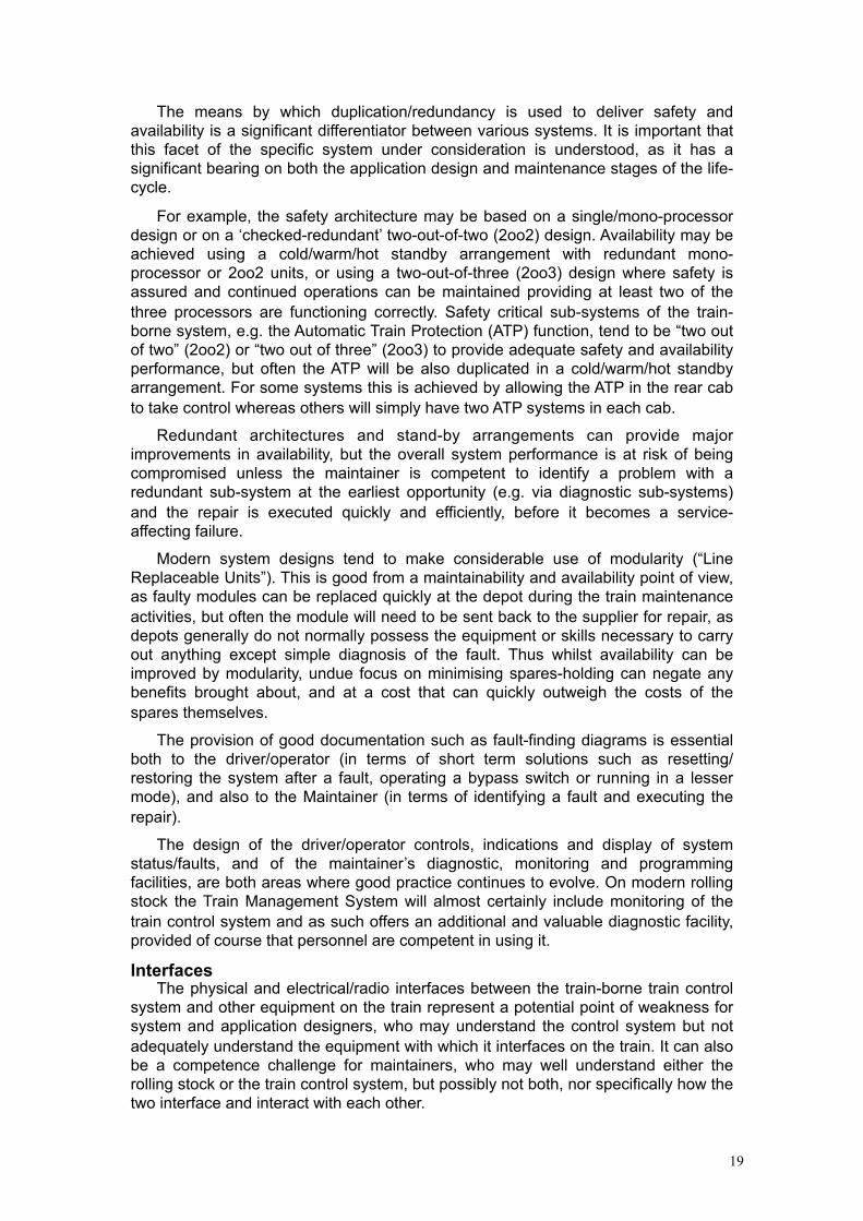
InterfacesThe physical and electrical/radio interfaces between the train-borne train control
system and other equipment on the train represent a potential point of weakness for system and application designers, who may understand the control system but not adequately understand the equipment with which it interfaces on the train. It can also be a competence challenge for maintainers, who may well understand either the rolling stock or the train control system, but possibly not both, nor specifically how the two interface and interact with each other.

20
Some parts of the train control system are intrinsically part of the train. For instance the safety brake circuits and round train circuits, common to most rolling stock, will be conditioned by the outputs from the train control system. Therefore staff engaged in fault finding of these circuits must have a solid understanding of both the train and the train control system.
Having accurate, clear information about interfaces between the system and the rest of the equipment, and the dependencies between them, is important for both designers and maintainers.
Some parts of the train control system, for instance any equipment mounted to the bogies, will be affected every time the bogies are removed or replaced, and therefore existing rolling stock procedures will need to be modified to include the necessary uncoupling / coupling / re-testing of these devices. Typical examples are speed sensors, antennae, and balise readers.
Interactions between the train control system and other equipment on the train are not restricted only to interfaces. Systems can also suffer from “unintended interactions”, and designers need to be aware of these and of the limits of performance of the systems, as well as the environment in which they are expected to work. For example, the inability of speed sensors to cope with the level of shock and vibration transmitted from the track has been a common problem with many train control systems. Similarly, excessive heat in an equipment cubicle has necessitated in some cases the installation of fans to cool electronic components.
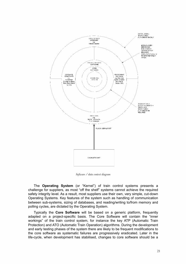
Software And DataThe software /data context diagram illustrates a typical Software / Data Context
Diagram for a train control system. The diagram suggests a highly modularised structure for the software and data contained within the train control system and although modern systems tend to adopt this approach, the same is not always true of older systems.
Like other critical software-based systems, train control systems use a variety of well- established techniques to defend against unauthorised / poorly executed modifications to software and data, but ultimately there is inevitably a dependency upon the competence of personnel engaged in programming and data preparation, particularly for non-standard elements.
21
Software / data context diagram
The Operating System (or “Kernel”) of train control systems presents a challenge for suppliers, as most “off the shelf” systems cannot achieve the required safety integrity level. As a result, most suppliers use their own, very simple, cut-down Operating Systems. Key features of the system such as handling of communication between sub-systems, sizing of databases, and reading/writing to/from memory and polling cycles, are dictated by the Operating System.
Typically the Core Software will be based on a generic platform, frequently adapted on a project-specific basis. The Core Software will contain the “inner workings” of the train control system, for instance the key ATP (Automatic Train Protection) and ATO (Automatic Train Operation) algorithms. During the development and early testing phases of the system there are likely to be frequent modifications to the core software as systematic failures are progressively eradicated. Later in the life-cycle, when development has stabilised, changes to core software should be a
22
fairly rare occurrence and, when they do occur, are more likely to be driven more by the customer requiring changes in functionality.
Software Constants embedded in the design of the system will normally remain fixed unless there is a fundamental change in the design parameters of the rolling stock or infrastructure. Software constants include parameters such as emergency brake rates, acceleration rates, brake build up time, communication time-out limits, and driver alert times.
The amount of train-borne Geographical Data (i.e. data relating to the routes over which the rolling stock operates) can vary considerably between systems, fundamentally being determined by the design philosophy for the system. In some systems, most commonly where the rolling stock is captive on a particular route, all the geographical data for the route may be held on the train. In other situations, where rolling stock moves more widely between routes, the geographical data may be held in the trackside systems and only communicated to each train on an “as needs” basis as it travels over a route. ERTMS is an example of the latter approach.
Whereas the Core Software and Software Constants are usually defined by Systems Engineers, Geographical Data is usually produced on an application-specific basis. Geographical Data is also likely to change during the service life of the rolling stock, since there is always a likelihood of revised track layouts, changes to switches, gradient modifications, different stopping positions etc. In systems where this data is held on the train, rather than in the infrastructure systems, there need to be arrangements in place for updating the data on each train in a fleet whenever required. The extent to which this is an automated process and contains in-built protection against human error will determine the competence requirements of those involved both in generating the data and in downloading it onto the trains.
User-defined variables are intended to be modified at regular intervals by the Maintainer. On modern systems, if the wrong value is inputted, the system should always fail in a safe manner, although there will of course be an impact on availability. The most common example of a user-defined variable is the wheel diameter, which needs to be modified following wheel replacement or turning. On some systems there will be a user-defined variable for train length, eg for freight trains which are not usually of a fixed formation, and this variable may have to be inputted by the train operator/driver or train preparer. Again, competence issues in relation to error-free data input are heavily dependent upon the system design and the associated procedures.
Finally, data logs of system performance are usually available and can be downloaded and interrogated by the Maintainer. On modern systems this is achieved using a diagnostic tool, often a PC or sometimes a specially adapted hand-held type device.
System Complexity And Configuration ControlSystem complexity is an important factor in terms of assessing the risks and
determining the appropriate level of competence of personnel working on train-borne train control systems, at all stages of the life-cycle.
Most train control systems are inherently complex, and ones that are involve both trackside and train-borne systems particularly so. Not only that, but also different versions of the same basic system will almost certainly exist.
The overall trend is towards greater interoperability (allowing trains to operate across different rail networks, rather than being constrained by the peculiarities of the train control system on each network) and, to some extent, physical inter-
23
changeability of different manufacturers’ subsystems. These advances bring with them additional systems integration, safety assurance and configuration management issues, which then impact upon the competence requirements of designers, maintainers and others.
The complexity of train-borne train control systems, and the importance of good configuration management, is exacerbated by the fact that the design configuration of trains vary, even within fleets, and this may affect the configuration of the train control system.
Modern train control systems usually include design features to prevent the maintainer from making unauthorised changes to the configuration. These are provided primarily to protect against safety hazards and will include features such as hardwired cab identification codes, pin-codes (for plug-in components), checksums (for uploading of new software/data) and access restrictions (to prevent unauthorised users from using diagnostic and programming devices). But there will be aspects of the configuration that have no such defences other than relying on the competence of the individual making the change.
Differences Between Train Control SystemsWhatever their superficial similarities, not all train-borne train control systems are
the same in terms of their design and modes of operation, and it is helpful to be aware of the significant differences between them.
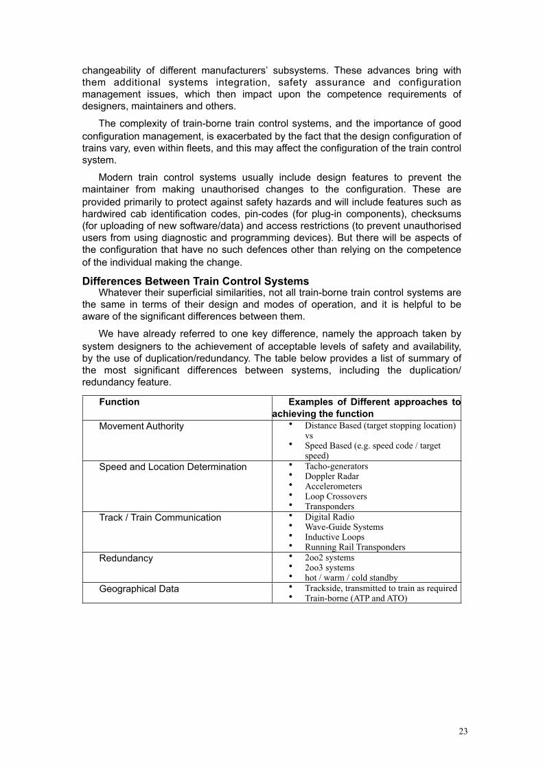
We have already referred to one key difference, namely the approach taken by system designers to the achievement of acceptable levels of safety and availability, by the use of duplication/redundancy. The table below provides a list of summary of the most significant differences between systems, including the duplication/redundancy feature.
Function Examples of Different approaches to achieving the function
Movement Authority • Distance Based (target stopping location) vs
• Speed Based (e.g. speed code / target speed)
Speed and Location Determination • Tacho-generators• Doppler Radar• Accelerometers • Loop Crossovers • Transponders
Track / Train Communication • Digital Radio• Wave-Guide Systems • Inductive Loops • Running Rail Transponders
Redundancy • 2oo2 systems• 2oo3 systems• hot / warm / cold standby
Geographical Data • Trackside, transmitted to train as required• Train-borne (ATP and ATO)
24
Examples
of ATP/ATC systemsLZB As Example Of A Continuous System
The LZB system was specified by UIC in the 1960s. A first implementation was built between Augsburg an Munich in 1965, where a maximum speed of 200 kph was demonstrated in passenger traffic. In 1972, a first line between Hamburg and Bremen was taken into operation, which was based on a 2-out-of-3 computer system. Since then, all high speed lines in Germany were equipped with this system. Spain and Austria also adopted the computer based LZB system and lines in both countries are in operation.
System SummaryIn the LZB system, all fixed data (i.e. line geography, permanent speed
restrictions) are stored in the LZB centre. The interlocking systems forward signal aspects, point settings and other element data to the control centre, the trains within the range of the system transmit their specific data, e.g. train length, train position, actual speed, etc.
From this data the control centre determines for each train the target values such as distance to stopping point which then are converted on board to a maximum permissible speed. Since signal settings for several block sections ahead are forwarded, the maximum speed can be increased and the maximum braking distance can be longer than the signal aspects of existing lineside signalling would allow.
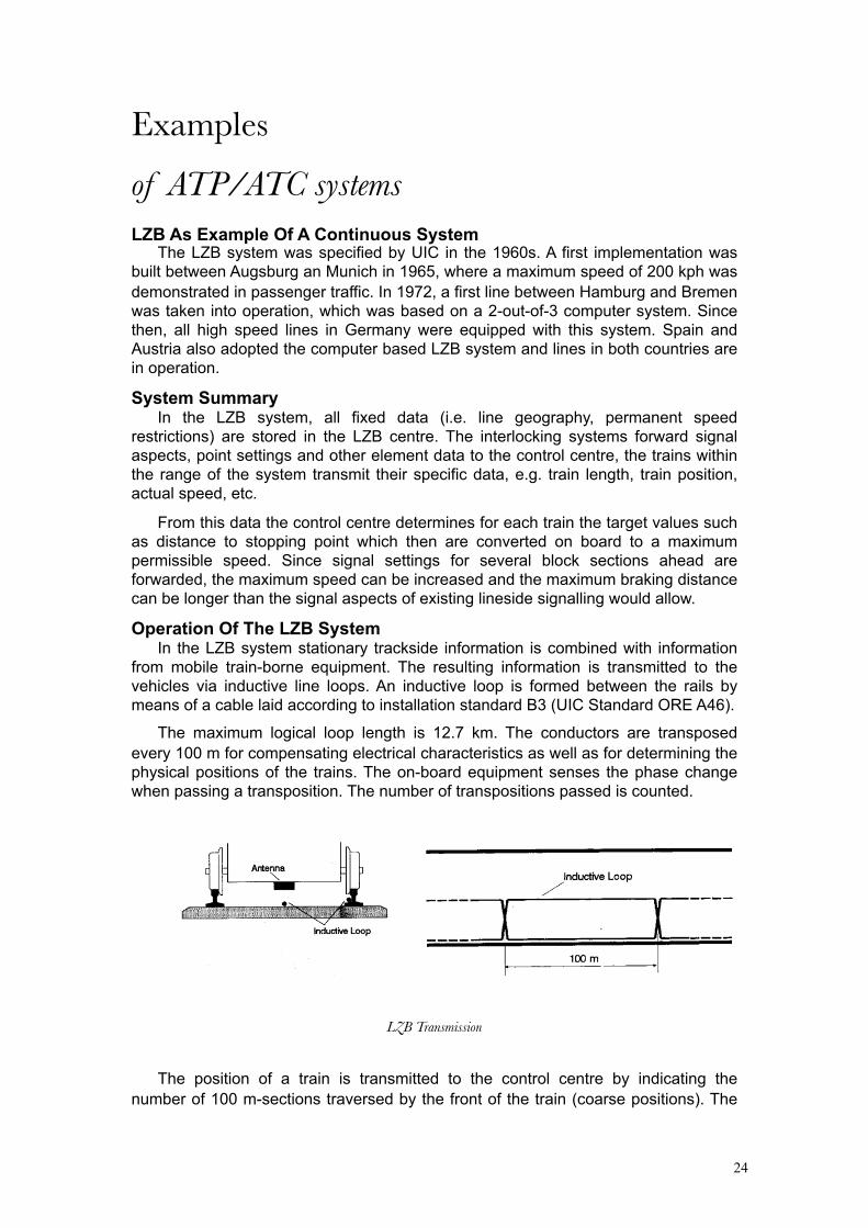
Operation Of The LZB SystemIn the LZB system stationary trackside information is combined with information
from mobile train-borne equipment. The resulting information is transmitted to the vehicles via inductive line loops. An inductive loop is formed between the rails by means of a cable laid according to installation standard B3 (UIC Standard ORE A46).
The maximum logical loop length is 12.7 km. The conductors are transposed every 100 m for compensating electrical characteristics as well as for determining the physical positions of the trains. The on-board equipment senses the phase change when passing a transposition. The number of transpositions passed is counted.
LZB Transmission
The position of a train is transmitted to the control centre by indicating the number of 100 m-sections traversed by the front of the train (coarse positions). The

25
count of coarse positions is dependent on the direction of travel of the train within the length of an inductive loop. A second, independent fine positioning procedure installed on the locomotive allows to transmit the position of the train within each 100 m-section with a quantisation of 12.5 m (fine position).
The train control commands computed by the control centre are transmitted to the corresponding LZB train via a remote feeding device, inductive line conductors and antennae, and are processed by the trainborne LZB unit and forwarded to a control panel as well as to the ATO system. Normally the nominal speed (V/nominal), the actual speed, the speed to be reached within a determined distance (target speed), and the distance to the target point are displayed.
LZB Cab display
The actual speed of the trains is continuously monitored by the on-board equipment. If it exceeds the nominal speed by a certain permissible value, emergency braking is automatically activated.
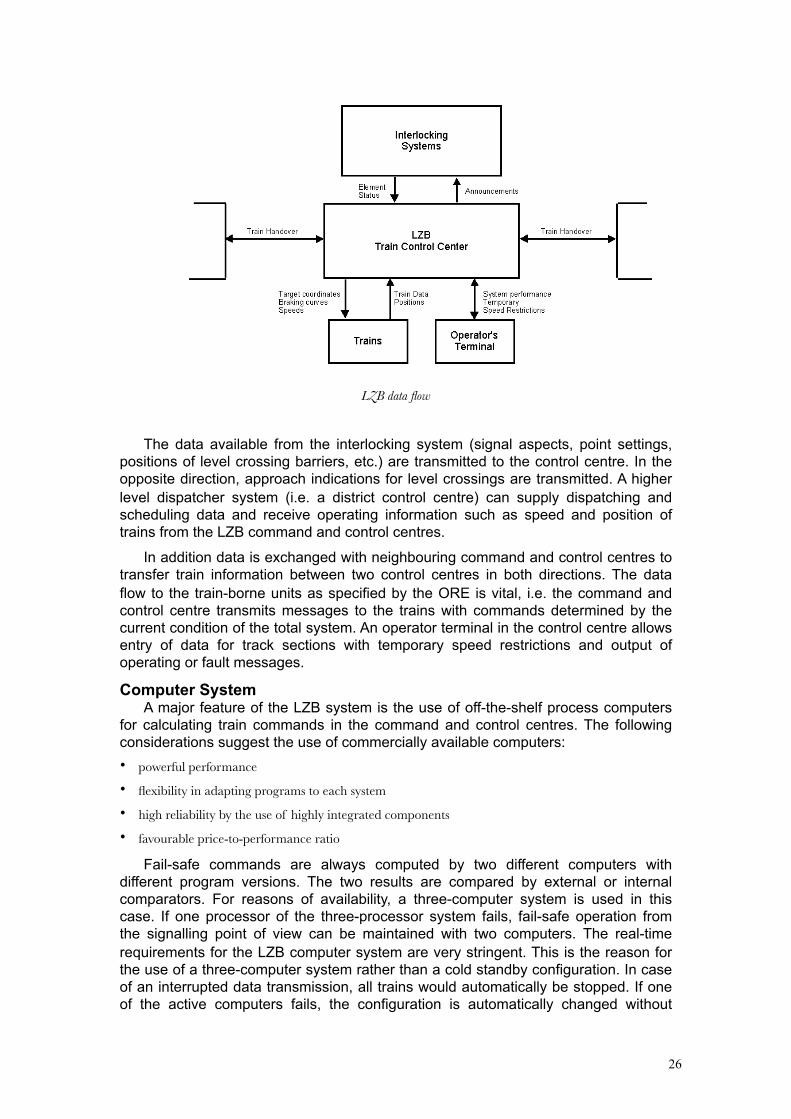
Command And Control CentreThe block diagram below illustrates the data flow between a LZB line centre and
its associated peripherals.
26
LZB data flow
The data available from the interlocking system (signal aspects, point settings, positions of level crossing barriers, etc.) are transmitted to the control centre. In the opposite direction, approach indications for level crossings are transmitted. A higher level dispatcher system (i.e. a district control centre) can supply dispatching and scheduling data and receive operating information such as speed and position of trains from the LZB command and control centres.
In addition data is exchanged with neighbouring command and control centres to transfer train information between two control centres in both directions. The data flow to the train-borne units as specified by the ORE is vital, i.e. the command and control centre transmits messages to the trains with commands determined by the current condition of the total system. An operator terminal in the control centre allows entry of data for track sections with temporary speed restrictions and output of operating or fault messages.
Computer SystemA major feature of the LZB system is the use of off-the-shelf process computers
for calculating train commands in the command and control centres. The following considerations suggest the use of commercially available computers:• powerful performance
• flexibility in adapting programs to each system
• high reliability by the use of highly integrated components
• favourable price-to-performance ratio
Fail-safe commands are always computed by two different computers with different program versions. The two results are compared by external or internal comparators. For reasons of availability, a three-computer system is used in this case. If one processor of the three-processor system fails, fail-safe operation from the signalling point of view can be maintained with two computers. The real-time requirements for the LZB computer system are very stringent. This is the reason for the use of a three-computer system rather than a cold standby configuration. In case of an interrupted data transmission, all trains would automatically be stopped. If one of the active computers fails, the configuration is automatically changed without
27
interrupting the data flow to the trains. A notification message on the operator terminal informs the maintenance personnel.
In this manner a three-computer system offers safety by means of tripling of computers. The final logic element, the output selector unit, is constructed according to fail safe techniques. A failure of any of its components results directly in a blocking of the data flow, inhibiting any erroneous output. If a train receives no messages from the LZB centre, the train-borne unit is automatically disconnected. The train continues to travel under the driver’s control at a reduced speed (max. 160 kph) in the conventional signalling system.
This Three Computer concept has been built accordingly for the train-borne equipment, based on microcomputer technology.
Data CommunicationData communication between the control centre and the trains is via inductive
line conductors and train-board antennae. A control centre handles a maximum of sixteen inductive line loops. This is equivalent for example to a two track section of about 40 km length with 10 siding tracks.
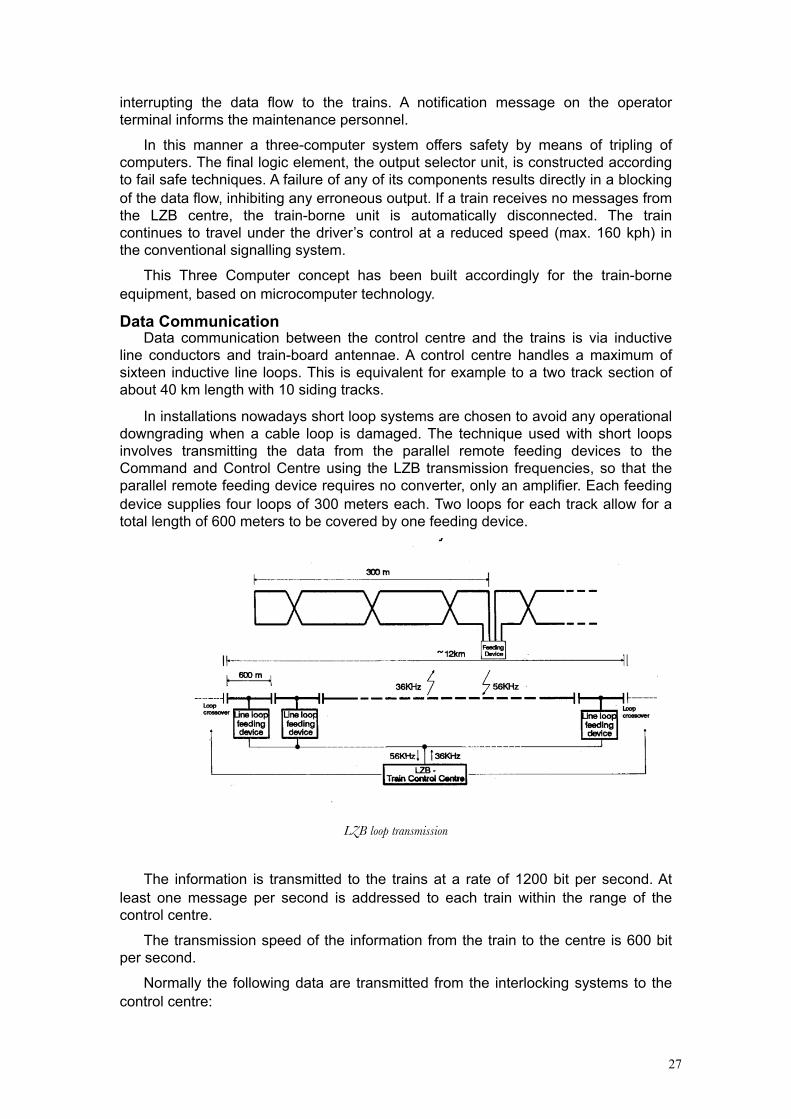
In installations nowadays short loop systems are chosen to avoid any operational downgrading when a cable loop is damaged. The technique used with short loops involves transmitting the data from the parallel remote feeding devices to the Command and Control Centre using the LZB transmission frequencies, so that the parallel remote feeding device requires no converter, only an amplifier. Each feeding device supplies four loops of 300 meters each. Two loops for each track allow for a total length of 600 meters to be covered by one feeding device.
LZB loop transmission
The information is transmitted to the trains at a rate of 1200 bit per second. At least one message per second is addressed to each train within the range of the control centre.
The transmission speed of the information from the train to the centre is 600 bit per second.
Normally the following data are transmitted from the interlocking systems to the control centre:
28
• signal aspects
• point settings
• positions of level crossing barriers
• emergency stop (controlled by the interlocking system).
Each change of these data, especially any change of the signals and the level crossing barriers, has to be forwarded to the computer with as little delay as possible. If the channels of the interlocking systems are utilised to full capacity, the message containing an information change arrives at the master station after a maximum delay of 0.4 seconds.
In the opposite direction all interlocking systems are addressed via a common channel with each system having a different address. Normally, transmissions contain level crossing approach messages, commands for setting signal marker lights, as well as fault and operating state data of the LZB Command and Control Centre.
The data exchange between adjacent centres mainly consists of data for transferring trains. This exchange is effected over data transmission systems using the transmission speed specified by the ORE.
Software For The LZB CentreSince high processing speed is required, all lists and programs needed for the
operating procedures are memory-resident. External mass storage cannot be used since access times are too long.
The most important data lists are the track section list and the train list. The track section list contains the coded track geography with fixed data (positions of the line components, track grades, track sections with permanent speed limits, entry/exit points on the loops, system boundaries) and the variable data (settings of the line components, track sections with temporary speed limits, emergency stop controlled by train and by control tower) of the total system.
In contrary to the static track section list which is permanently coded, the train list is a purely dynamic list. The specific data of all trains within the system area are entered for each program in this train list, monitored and cancelled upon departure. The structure of the train list ensures that each LZB train knows the positions of the preceding or following train (list chaining).
The main task of these programs is the determination of the maximum permissible braking distance for each train within the system area. To calculate the information for a train, input data from interlocking systems and adjacent controllers as well as the last message sent by the train have to be processed. In addition, the messages for the interlocking systems and adjacent controllers are prepared, operator monitor input is processed and possible fault and operating indications are transmitted.
SELCAB An Example Of An Intermittent SystemOne of the most challenging requirements to an ATP system is not to reduce line
capacity. That means that on lines where throughput is critical, an upgraded signal aspect has to be transmitted with a minimum delay in order to avoid unnecessary braking and longer headways. This can be achieved by a semi continuous transmission system. In SELCAB transmission is based on LZB principles as described above. The length of the loop can vary according to the headway requirements. The loop will always be laid out in rear of the signal, allowing the vehicle to pick up the information of the signal continuously when positioned over the
29
loop. Also when the train is stopped at a signal at danger, data transmission is guaranteed and the information transmitted will allow the train to accelerate when the signal has cleared and at the same time prevent a vehicle to start against a signal at danger. For non critical lines carrying low traffic, the length of the loop can be restricted to a minimum given by the maximum train speed and minimum time required to transmit the necessary information.
The use of a standardised means of transmission also has the advantage of well proven reliability and safety of the transmission method and also of the equipment.
The main characteristics of this data transmission method specified in ORE A46 are:• Telegram length 83 Bits
• Hamming distance of 4
• 70 user defined bits per telegram
• 1200 Baud transmission rate
• FSK modulation
• Carrier 36 kHz +/- 400 Hz
• Current 100 mA - 200 mA.
The information for the train is generated locally at the signal by sensing the signal aspect and combining it with track specific data. This information is then sent to the vehicle on the loop, which picks up the magnetic field, decodes the telegrams and reacts accordingly.
The main difference to the LZB system is:• No central trackside processing centre, local generation of information.
• No continuous loop layout, only in rear of signals.
• No addressing of trains, as only one train can be over the loop at a time.
• No transmission from train to track.
Therefore, the selected system has a more decentralised structure and needs less infrastructure.
As the data transmission characteristics are identical for SELCAB and LZB, the LZB trainborne equipment can run over both systems. Therefore, an upgrade of the line capacity based on a moving block system is possible by upgrading the trainborne equipment for train to track transmission.
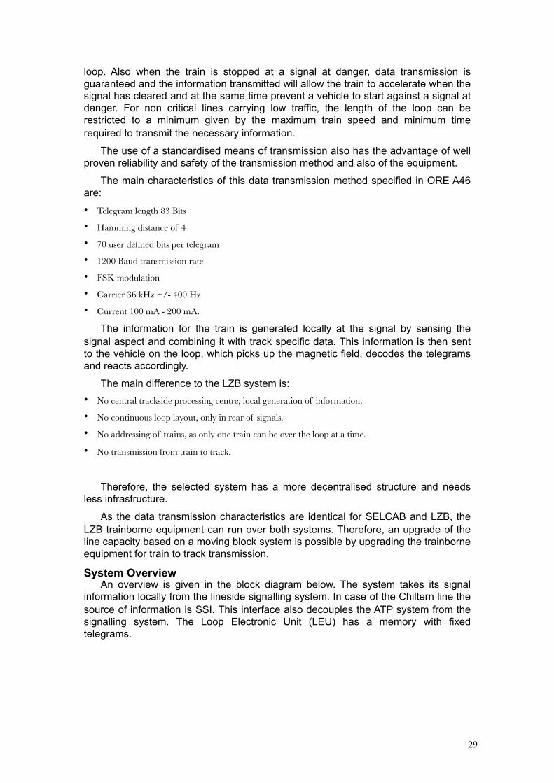
System OverviewAn overview is given in the block diagram below. The system takes its signal
information locally from the lineside signalling system. In case of the Chiltern line the source of information is SSI. This interface also decouples the ATP system from the signalling system. The Loop Electronic Unit (LEU) has a memory with fixed telegrams.
30
SELCAB transmission
The number of sets of telegrams depends upon the number of signal aspects which can be shown by the individual signal. Each set of telegrams corresponds to one signal aspect. The selection of the appropriate set of telegrams is made by the information picked up from the signal. The serial telegrams are frequency modulated and transmitted to trains via the inductive loop. The length of the loop can vary between 5 metres and 300 metres depending on the operational requirements (headway) of the line. As in LZB, the loops have transpositions which are used for the position measurement on board and cancel the effect of electromagnetic coupling to the rails. The information is picked up from the magnetic field of the loop cable by two onboard antennae. The rear antenna serves as a phase reference for the detection of transposition on the loop.
The vehicle on-board controller (VOBC) itself is a vital processor system in checked redundancy configuration which does all the scanning of the inputs decoding of telegrams, calculation of the various braking curves, speed supervision interfacing the driver’s Interface Unit (DIU) and the interfaces to the vehicle.
The position measurement system is based on three independent sensors:• detection of transpositions of the loop cable (antennae)
• measurement of wheel revolutions (tachogenerators)
• measurement of acceleration/deceleration (accelerometer).
The driver’s Interface Unit itself is processor based, it handles the information flow between the data entry terminal and the VOBC and also drives the speedometer.
Operational RequirementsSELCAB uses a vital system, the driver has to be informed about the main
restrictions of the line ahead and the train is supervised by the system. It is essential that the driver still has the responsibility for the movement of the train, but in case of not reacting according to the lineside signals or to speed restrictions, the train will be braked automatically.
The main functions are:• Monitoring of train speed in relation to line speed, permanent and temporary speed restrictions,
based on train characteristics.

31
• Supervision of braking to speed restrictions imposed by track characteristics or by signalling.
• Indication of line and signal information to the driver (cab signalling).
Trackside EquipmentThere are three main components:
• Signal Interface Unit
• Loop Electronics Unit
• Cable loop
The loop cable is fixed to the track by clips attached to the flange of the rail, to sleepers and by covers attached to the sleepers over each loop crossover, or loop end. The covers protect the loop from damage by people walking on the track, or from dragging equipment. The SELCAB track loops do not infringe the ballast tamping zone and therefore it is possible to carry out periodic track maintenance with the loops in place.
The Loop Electronics Unit (LEU) consists of two telegram generators which are independent of each other, feeding their information through selection logic to the modulator/transmitter. Each of the two telegram generators reads the signal information from the six input lines. These inputs form a dual code, therefore 26 = 64 different combinations can be defined. Each defined state selects a certain set of telegrams.
The information for selecting the correct set of telegrams is derived from the signal aspect.
Trainborne EquipmentThe onboard equipment for the Chiltern Line is based on LZB trainborne
equipment for urban traffic. The processor system itself is a 2 out of 2 configuration, where the two microprocessors work independently and compare their outputs by exchange of data. In normal operation, each of the computers outputs a life signal, which is individually supervised for correct sequence of pulses by a supervision board. Only if both supervision boards receive proper life signals, the emergency brake is released.
Outputs to the vehicle are by means of standard industrial non vital relays. For vital outputs, two relay contacts of different relays driven by different processors are used.
Parallel input data are fed to the processors by optocouplers. Where vital operation is required, two independent optocouplers read the information.
Operation Of The SELCAB SystemThree types of supervision are implemented:• Train trip (when passing a signal at danger)
• Continuous supervision of speed
• Rollback supervision
The continuous supervision function can be split into two subtasks:
• Supervision of a constant permissible speed which also is indicated to the driver. The system warns the driver and applies the service brake in case of no appropriate reaction.
• Supervision of the braking action of the train. A number of continuous braking curves is calculated on board which each causes a defined reaction when being exceeded.
32
The first curve (indication curve) gives a brake announcement and initiates the indication of target data. The second curve (warning curve) generates an audible alarm. The third curve (service brake curve) automatically applies the service brake which can only be released after the permissible speed is reached. The last curve is only activated in case of a failure of the service brake (Emergency brake curve).
This brake can only be released when the vehicle has come to a complete stop.
All curves except the emergency brake curve are oriented at the position of the signal. In case of an emergency brake application the vehicle is stopped within the overlap. This curve points to the end of the overlap.
If there is more than one target transmitted, a minimum selection for the actual position of the vehicle is made. Up to four targets can be processed at a time.
Glasgow CTS Contactless Trainstop This description was reproduced with permission from an article in IRSE News
109, November 2005 by Ed. Gerrard and David Hughes.
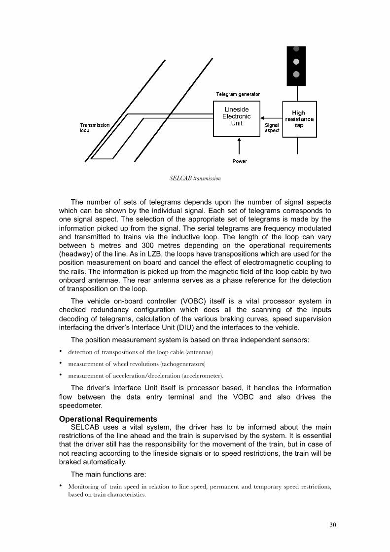
CTS Trackside Equipment Architecture And Operation
Figure one shows the CTS Trackside equipment architecture. The track beacon comprises two polarised permanent magnets and two coils, a signal coil and a feedback coil and these coils are mutually coupled.
Housed in the local Station Switchroom there is a transmitter, which is switched on by a call for the corresponding signal to be switched to Green (DR). This sends a 25.6 kHz signal to the beacon signal coil to disarm the beacon. To prove that the beacon has been disarmed a beacon feedback coil picks up the signal and feeds it back to a detector which on receipt of this feedback signal energises a relay (CTSPR).
This interfaces with conventional train stop circuitry using the VPR and VCR relays. These proving relays then allow the trackside Signal lamp to be switched to Green if both DR and CTSPR/VPR are energised. If the Signal is at Red then there is no transmitter signal and the Beacon is armed. In this scenario only the permanent polarised magnets are present and both the DR and CTSPR/VPR are de-energised.
33
Contacts of the DR and CTSPR relays are monitored and if they are out of correspondence for whatever reason, a train stop alarm is given through the Supervisory System in the central control room. This alarm can then be reported to the maintenance department so that action may be taken.
As per the existing mechanical train stop system in normal operation, the disarming of a beacon at Station one, due to the signal being at Green, prevents the Station two in rear train stop from disarming and clearing that station's protecting signal until the train at Station one is clear of Station one's Overlap. In the event of a train passing through Station one train stop, which does not eventually re-arm, then the protecting signal in rear at Station two will not clear, even though the leading train has cleared the forward protected section. In this situation a train stop failure alarm for Station one is given in the central control room.
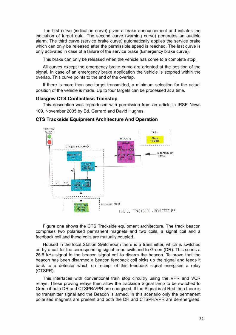
CTS Train Carried Equipment Architecture And Operation
Figure two shows the CTS Train Carried base architecture. The traincarried sensor consists of two saturable coils and an aerial. The two saturable coils are connected to two separate oscillator circuits, which are ultimately connected to a logic array decoder, and a Signal aerial whose signal is again
connected into a logic array decoder. When the train passes over a beacon with only the permanent polarized magnets and no frequency signal, in the correct direction, the saturable coils kill the two oscillators and an Emergency Brake Application is actuated through the logic array, interface card and brake solenoid.
When the train passes over a beacon that is energised by the 25.6 kHz signal, this frequency signal is detected first and suppresses the train trip called for by the saturable coils passing over the permanent magnets. A short comfort beep is given to the driver to indicate that the CTS system has just passed over a disarmed beacon and is operating normally. In the event that the Sensor sees only a 25.6 kHz signal and not the permanent magnets, then an audible alarm is given to the Driver indicating an error. The driver will then be required to obey restrictive operational rules in this situation.
In passenger service the normal mode of driving is Automatic (ATO) with the possibility of the train being driven in Unrestricted Manual mode. In the event of a Trip at a red signal that produces an emergency brake application the operator is
34
required to reset the train-carried CTS unit. Upon resetting the CTS unit the driving mode is automatically forced to 'Restricted Manual' operation
(25 km/h speed limit). This speed limit remains in force until the train passes a valid disarmed (green) beacon, which will usually be at the next station. When the on-board CTS unit receives the signal from this valid beacon, then the speed restriction is automatically removed and normal driving is re-established.
The main CTS train-carried control equipment is installed under one of the lockable passenger seats. The driver interface and controls (reset etc.) for the CTS system are installed within the cab area in a locked enclosure for access when required.
The maximum speed on Glasgow Subway is only 60 km/h though the specification for the train-carried equipment is quoted as able to trip vehicles travelling up to 250 km/h.

35
ERTMS /ETCSThe existing train control systems in Europe are neither compatible nor
interoperable. Before the advent of high-speed international trains this fact was not a major problem. International traffic did not make up a large proportion of rail traffic and international trains had to change their locomotive at borders anyway. Where regular cross-border traffic existed, country specific locomotives or trainsets equipped with the specific catenary and train control systems needed, operated by national drivers provided bi-laterally agreed specific solutions in the past, such as the Benelux trains and the Amsterdam-Brussels-Paris TEE trains. The introduction of the high speed trains in Europe opened up a new market for high speed passenger traffic and allowed the European High Speed networks to be created. With the introduction of multiple unit high speed trains designed specifically for this market segment, such as the TGVs, ICEs and the Eurostars, the ATP/ATC situation became more complicated. These trains have to be multiple equipped with all train control systems of the countries they are planned to travel to when they are to be admitted on the networks.
The treaty of Rome, founding the European Community, mandates the European Commission to develop integrated international transport networks. The European transport policy calls for a revival of Rail transport, both Passenger and Freight. This is to be achieved by opening up the national rail networks to new entrants, a separation of the responsibilities for infrastructure and operation and a system of technical harmonisation removing barriers to cross-border traffic. The existing national ATP systems, most of which are not only incompatible, but also proprietary to a specific railway and/or supplier, was identified as an important obstacle to achieving these goals. Following the decision taken by the European Transport minister in December 1989, the EC embarked upon a project to analyse the problems relating to signalling and train control. At the end of 1990, the European rail research Institute (ERRI) created a group of railway experts (ERRI A200) to develop the specification of requirements of ETCS. In June 1991, Industry ( Eurosig ) and Railways ( UIC, ERRI A200) agreed the principles of tight co-operation in order to consider the requirement specifications as the base for industrial development. The project framework included a new on-board equipment based on open computer architecture (Eurocab), a new intermittent system for data transmission, (Eurobalise) and a new continuous transmission system (Euroradio). At the end of 1993, the EU council issued an Interoperability Directive and a decision was taken to create a structure to define the Technical Specification for Interoperability.
The two major elements of ERTMS at present are the train control system (ETCS) and the common train radio system for voice and data communication GSM–R.
The High-Speed interoperability directive 96/48 mandates a system of interface specifications (TSI’s) between subsystems making up a high speed railway, of which ERTMS/ETCS is the command and control subsystem. This principle was subsequently extended to the Conventional Rail international network by directive 2001/16.
In 1995 the EC defined a global strategy for the further development of ERTMS with the aim to prepare its future implementation on the European Rail Network. The global strategy described in the "Master Plan of Activities" included the development and validation phase. The objective of the validation phase was to perform full scale
36
tests on sites located in different countries (France, Germany and Italy). In the summer of 1998, Unisig, comprising the European Signalling companies was formed to finalise the specifications. The ERTMS specification, Class 1, was accepted on 25th April 2000, Interoperability tests were carried out on the Madrid-Seville (EMSET) test track and the Vienna-Budapest trials. The Test Track in Italy carried out trials in 2001 and trials in several other countries, such as Germany (Jüterborg-Halle-Leipzig), France and the Netherlands followed. The results of all these trials were incorporated in the consolidated specifications SRS 2.2.2C, which have been approved in 2005 and are the basis for the revision of the Command Control and Signalling Technical Specifications for High-Speed and Conventional Rail.
ERTMS/ETCS is now available for implementation. ERTMS/ETCS is available in both Level 1 and Level 2 variants, with Level 3 still to be developed.
ERTMS/ETCS has been in commercial operation in various countries since 2005/2006 (Germany, Italy, Luxembourg, the Netherlands, Spain, Switzerland) and will be implemented in other countries soon, including Austria, Belgium and Hungary.
The Rome-Naples line was the first ERTMS/ETCS level 2 line to enter commercial service in January 2006. In Switzerland two lines (Berne-Olten and the Lötschbergtunnel) are in commercial service, both employing ERTMS/ETCS level 2. Over 600 vehicles in more than 20 differing types of rolling stock are running each day (Levels 1 and 2) and much experience has been gained to enable the production of the latest technical baseline (SRS version 2.3.0)
The Swiss projects have contributed much to the maturity growth of the ERTMS/ETCS products and specifically towards resolving remaining issues of interoperability between various supplier implementations of ERTMS/ETCS, resulting in SRS 2.3.0
The ERTMS specifications are managed by the European Railway Agency acting as the ERTMS/ETCS system authority and Change Control Board.
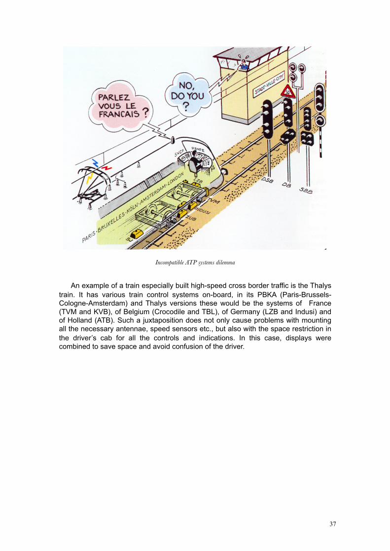
37
Incompatible ATP systems dilemma
An example of a train especially built high-speed cross border traffic is the Thalys train. It has various train control systems on-board, in its PBKA (Paris-Brussels-Cologne-Amsterdam) and Thalys versions these would be the systems of France (TVM and KVB), of Belgium (Crocodile and TBL), of Germany (LZB and Indusi) and of Holland (ATB). Such a juxtaposition does not only cause problems with mounting all the necessary antennae, speed sensors etc., but also with the space restriction in the driver’s cab for all the controls and indications. In this case, displays were combined to save space and avoid confusion of the driver.
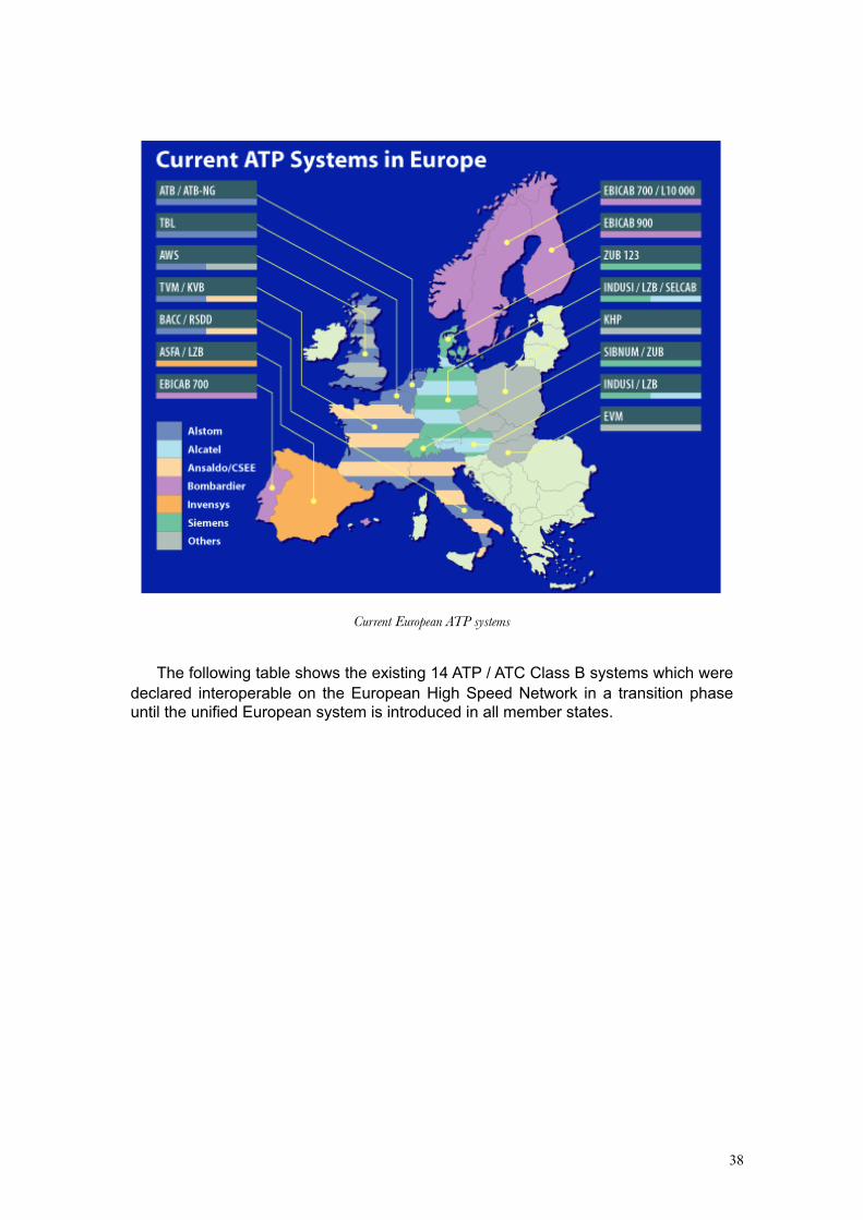
38
Current European ATP systems
The following table shows the existing 14 ATP / ATC Class B systems which were declared interoperable on the European High Speed Network in a transition phase until the unified European system is introduced in all member states.

39
Table 1 Interoperable ATP systems
Levels Of ApplicationBeing a harmonised European system, ERTMS/ETCS has to comply with the
very diverging requirements for ATP/ATC systems in Europe. The common system shall cover the wide spectrum from low traffic secondary lines to high speed lines carrying dense traffic. The technical solutions have to offer an economically optimised system. On the other hand, there should be no restrictions in the use of vehicles in the various railways; this means that the on-board equipment should be able to interpret all equipment levels installed lineside.
The system was designed to be applied on the following levels:
• Level 1 is provides an intermittent ATP system, using spot or semi continuous transmission only. Conventional lineside signalling (i.e train detection, interlocking and block systems and lineside signals) are its base, but the system can also be applied without lineside colour light signals, using block-markers and indication lights, as practiced on the Dutch and Belgian sections of the Amsterdam-Brussels-Paris high speed corridor. On that line it provides a fall-back option from the normal ETCS level 2 operation.
ETCS level 1
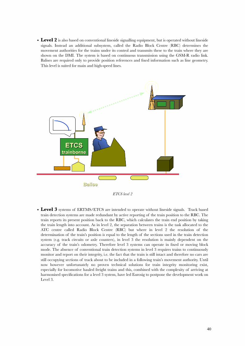
40
• Level 2 is also based on conventional lineside signalling equipment, but is operated without lineside signals. Instead an additional subsystem, called the Radio Block Centre (RBC) determines the movement authorities for the trains under its control and transmits these to the train where they are shown on the DMI. The system is based on continuous transmission using the GSM-R radio link. Balises are required only to provide position references and fixed information such as line geometry. This level is suited for main and high-speed lines.
ETCS level 2
• Level 3 systems of ERTMS/ETCS are intended to operate without lineside signals. Track based train detection systems are made redundant by active reporting of the train position to the RBC. The train reports its present position back to the RBC, which calculates the train end position by taking the train length into account. As in level 2, the separation between trains is the task allocated to the ATC centre called Radio Block Centre (RBC) but where in level 2 the resolution of the determination of the train’s position is equal to the length of the sections used in the train detection system (e.g. track circuits or axle counters), in level 3 the resolution is mainly dependent on the accuracy of the train’s odometry. Therefore level 3 systems can operate in fixed or moving block mode. The absence of conventional train detection systems in level 3 requires trains to continuously monitor and report on their integrity, i.e. the fact that the train is still intact and therefore no cars are still occupying sections of track about to be included in a following train’s movement authority. Until now however unfortunately no proven technical solutions for train integrity monitoring exist, especially for locomotive hauled freight trains and this, combined with the complexity of arriving at harmonised specifications for a level 3 system, have led Eurosig to postpone the development work on Level 3.

41
ETCS Level 3
Data TransmissionFor spot transmission, the Eurobalise was standardised. The technology is similar
to the equipment used in Sweden (Ebicab) and France (KVB), but has improved performance. The trackside equipment is based on passive transponder technology, which means that it needs no external power supply for data transmission to the train. The coupling between the trackside balise and the balise transmission module underneath the train is inductive. The train constantly radiates a magnetic field with a frequency of 27.095 MHz, which is picked up by the wayside balise when the train is passing. The received power is used to feed the transmitter in the wayside balise, which generates a serial data stream back to the train-borne receiver. For the data transmission, a frequency range between 4 MHz and 5 MHz was chosen, the data rate is 600 kbit/s.
There are two applications of the Eurobalise, depending on the level of ERTMS/ETCS. In level 1, the Eurobalise transmits signal information, which is variable information. Other parts of the data telegram can be fixed, such as distance to the next balise, maximum line speed or line gradients. These balises are connected to a lineside electronic unit (LEU), similar to the one described for the SELCAB system. The other application is mainly in level 2 or level 3 systems for positioning purposes. As the train cannot derive information on its position from the radio transmission system, the balises carrying fixed information are used to allow the train to evaluate its position when passing a balise. The interpolation between balises is performed by an on-board Speed and Distance Monitoring Unit (SDMU). For this function, a selection of sensors, such as tachogenerators, radar speed sensors or others can be used, depending on the supplier’s choice.
For semi-continuous data transmission, that can be applied to transmit infill information in level 1 systems, a technology using a leaky cable is the preferred solution. The leaky cable in principle is a coaxial cable with the outer conductor carrying slots, so that a small portion of the transmitted power can leak out of the cable and be received by an on-board receiver, which can use the same antenna as the Eurobalise transmission unit. This so-called Euroloop is always carrying variable
42
signal information, it has to be actively powered from the wayside, its length can be up to several hundred meters.
To study the application of radio for ATC purposes, a research program named DIBMOF (services integrating railway mobile radio) was performed. It confirmed the concept of using the same radio system for voice communication between driver and central and data transmission. The base for radio communication was the GSM (Global System for Mobile communication) system, which was specified in Europe and has become a world-wide standard. Most of the public cellular networks in Europe are compatible with the GSM standard.
The International Union of Railways took a majority decision to introduce GSM as the base for voice and data transmission between train and ground. For railway applications, an exclusive transmission frequency range below the frequency of the public GSM band was recommended and granted. A survey was made to collect all the requirements from the member railways for such a radio system. The evaluation led to a system called GSM-R, where R stands for railways. This set of requirements was passed on to ETSI (European Telecommunication Standards Institute), who generated, based also on the requirements of others, the set of specifications GSM 2+. Most of the additional features requested by UIC and exceeding the GSM 2+ standard are only related to voice services. There is, however, one future important feature which permits short headways by reducing the time for establishing a connection to a train. This service is based on Internet protocols and is called GPRS (General Package Radio System).
A specific problem in transmitting vital signalling data over an open radio channel is that of safety and security. European standards define threats against which suitable defences have to be established:
• In the same way as in conventional systems, a protection against random errors caused by lightening or similar effects has to be in place. This is normally done by adding code bits to the message.
• Data are passed through a number of devices with unknown behaviour from transmitter to receiver. Therefore, the transmission path is frequently called a grey channel, which means that it is not totally transparent for the user. Coding strategies have to be used which allow the receiver to detect and reject corrupted messages.
• There may be an intrusion from external users of the open network which is common to public users and railway users. Therefore, protective coding has to be used to avoid unauthorised access to the data transmission between train and wayside.
Selection Of The Appropriate Level Of OperationThe same criteria as for existing systems apply to ERTMS/ETCS. For the
introduction or replacement of a simple ATP system, level 1 based on balises only is the most cost effective solution. There are, however, two aspects to be considered:
• As with any intermittent ATP system, there has to be sufficient overlap in the track layout to allow a train to stop within the overlap when it passes the signal at danger with the release speed of the system. AS discussed in chapters 3.1.1 and 3.1.2, this release speed is a trade-off between line
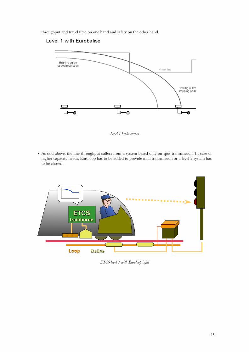
43
throughput and travel time on one hand and safety on the other hand.
Level 1 brake curves
• As said above, the line throughput suffers from a system based only on spot transmission. In case of higher capacity needs, Euroloop has to be added to provide infill transmission or a level 2 system has to be chosen.
ETCS level 1 with Euroloop infill
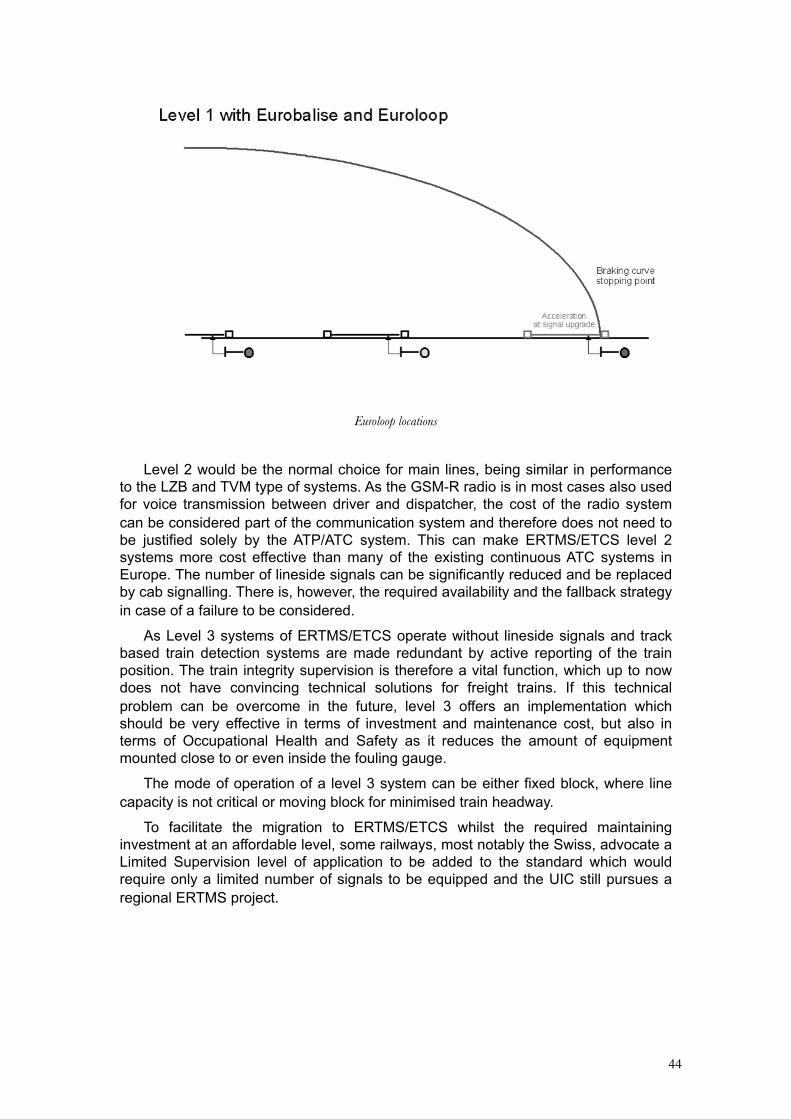
44
Euroloop locations
Level 2 would be the normal choice for main lines, being similar in performance to the LZB and TVM type of systems. As the GSM-R radio is in most cases also used for voice transmission between driver and dispatcher, the cost of the radio system can be considered part of the communication system and therefore does not need to be justified solely by the ATP/ATC system. This can make ERTMS/ETCS level 2 systems more cost effective than many of the existing continuous ATC systems in Europe. The number of lineside signals can be significantly reduced and be replaced by cab signalling. There is, however, the required availability and the fallback strategy in case of a failure to be considered.
As Level 3 systems of ERTMS/ETCS operate without lineside signals and track based train detection systems are made redundant by active reporting of the train position. The train integrity supervision is therefore a vital function, which up to now does not have convincing technical solutions for freight trains. If this technical problem can be overcome in the future, level 3 offers an implementation which should be very effective in terms of investment and maintenance cost, but also in terms of Occupational Health and Safety as it reduces the amount of equipment mounted close to or even inside the fouling gauge.
The mode of operation of a level 3 system can be either fixed block, where line capacity is not critical or moving block for minimised train headway.
To facilitate the migration to ERTMS/ETCS whilst the required maintaining investment at an affordable level, some railways, most notably the Swiss, advocate a Limited Supervision level of application to be added to the standard which would require only a limited number of signals to be equipped and the UIC still pursues a regional ERTMS project.
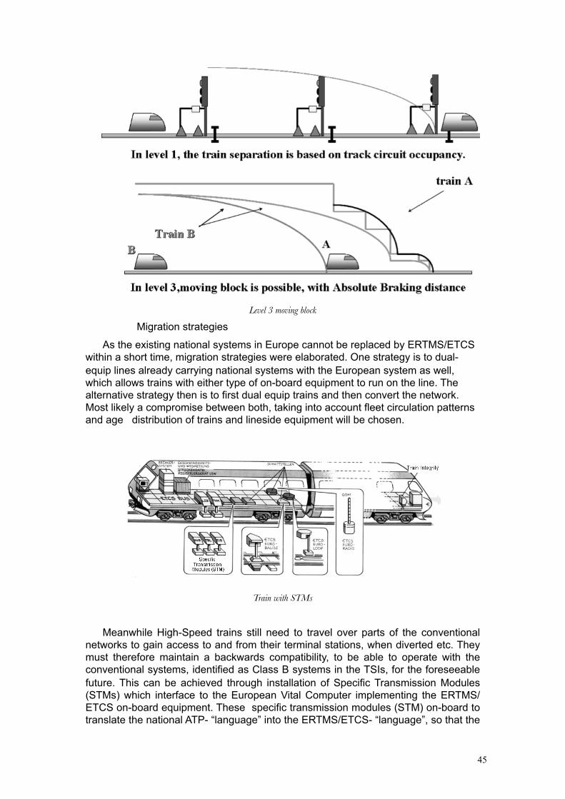
45
Level 3 moving block
Migration strategies
As the existing national systems in Europe cannot be replaced by ERTMS/ETCS within a short time, migration strategies were elaborated. One strategy is to dual-equip lines already carrying national systems with the European system as well, which allows trains with either type of on-board equipment to run on the line. The alternative strategy then is to first dual equip trains and then convert the network. Most likely a compromise between both, taking into account fleet circulation patterns and age distribution of trains and lineside equipment will be chosen.
Train with STMs
Meanwhile High-Speed trains still need to travel over parts of the conventional networks to gain access to and from their terminal stations, when diverted etc. They must therefore maintain a backwards compatibility, to be able to operate with the conventional systems, identified as Class B systems in the TSIs, for the foreseeable future. This can be achieved through installation of Specific Transmission Modules (STMs) which interface to the European Vital Computer implementing the ERTMS/ETCS on-board equipment. These specific transmission modules (STM) on-board to translate the national ATP- “language” into the ERTMS/ETCS- “language”, so that the
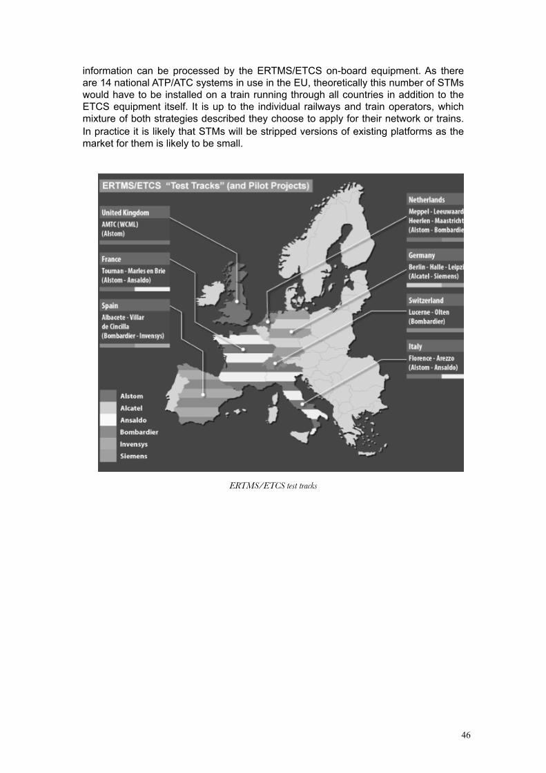
46
information can be processed by the ERTMS/ETCS on-board equipment. As there are 14 national ATP/ATC systems in use in the EU, theoretically this number of STMs would have to be installed on a train running through all countries in addition to the ETCS equipment itself. It is up to the individual railways and train operators, which mixture of both strategies described they choose to apply for their network or trains. In practice it is likely that STMs will be stripped versions of existing platforms as the market for them is likely to be small.
ERTMS/ETCS test tracks

47
ERTMS/ETCS commercial projects
48
Ensuring safe and reliable operationsReliability Issues
Implementing ATP / ATC systems involves putting “state of the art technology” on board fleets of trains and locomotives, for which the term harsh environment is an understatement. Especially antennae and speed sensors are prone to defects and [1], [3], [7] and [16] give some interesting insights.
Legal requirements usually demand a “No-ATP No-Go” policy to be implemented. E.g in the Netherlands a train with failed ATP equipment has to be taken out of service within 24 hours, is not allowed to drive through tunnels. Speed restrictions may be imposed. While these effects do not enter into our capacity models, passengers will doubtlessly notice the reduced performance and reliability of their train services.
Human FactorsIt is not unusual for drivers to be suspicious of ATP / ATC systems on
introduction. The combination of fear of de-skilling their jobs, zero-tolerance for SPAD regimes, defensive driving etc. can amplify the effect of system inherent safety margins on capacity. Experience in the Netherlands shows that it can take a generation of drivers to start to appreciate ATC / ATC systems for what they truly are, i.e. an aid to driving under difficult circumstances and an insurance against human error developing into catastrophe.
Careful consideration needs to be given to the human factors issues surrounding the introduction of any ATP/ATC system. Retrofitting cab signals and ATP/ATC controls to existing drivers desks can be very difficult and costly but also lead to problems with the Human Machine Interface. Furthermore the level and type of visual and / or acoustic indications needs to be considered. This must also be consistent with the chosen safety integrity level of the equipment design. For instance drivers may develop a tendency to rely on a horn to be sounded whenever a speed restriction or signal at danger is approached. There is even anecdotal evidence of drivers averting attention from the track until such a horn is sounded. There is however no way of making an active signal such as a horn failsafe, so one day it will not sound, perhaps as a result of something as trivial as a loose connection. This risk, which is particularly relevant to older generation intermittent ATP systems of non-failsafe design, needs to be balanced against the comfort factor provided by in cab indications when driving at higher speeds under conditions of poor visibility.
In the case of ERTMS/ETCS much time and effort has been devoted to a human factors study which involved numerous interviews with train drivers and tests of several conceptual designs in simulators before arriving at the present design for a harmonised Human Machine Interface.

49
AcknowledgementI would like to thank those friends and colleagues who have helped me to gain an
appreciation of train protection systems over several years, especially Helmut Uebel and David Fenner for permission to re-use parts of their papers on Train Protection systems and Ed. Gerrard and David Hughes for permission to reproduce their Glasgow CTS description.
50
References and Bibliography
1 ATP – The Train Operator’s perspectiveTechnical paper to the IRSE on 16th January 2002-01-29Nick Wright (First Great Western) and Andy Hamilton (Chiltern Railways)
2 Untersuchung des Leistungsverhaltens beliebiger SignaltechnikenJörg OsburgSignal&Draht, Jan+Feb 2002
3 Lessons Learned From the ATP pilot schemes in the UKResults of the cross industry seminar held in November 2000 under the aegis of the train protection steering group
4 The Capacity of Railways and Their Control Systems, University of Sheffield Msc Module Lecture, Daniel Woodland, 21/02/2002
5 Batenonderzoek VPT+, Railinfrabeheer internal report.6 Betriebliche Aspekte von Euroloop, Frösig/Uebel, Signal & Draht 10/20017 Experience with Train Protection Systems in the Netherlands, WJ
Coenraad, IMechE March 20038 Two Centuries of Railway Signalling - Geoffrey Kitchenside and Alan
Williams - OPC.9 Railway Disasters cause and effect - Stanley Hall - Ian Allan and
Bookmart Ltd.10 British Railway Disasters - Ian Allan.11 Historic Railway disasters - O.S. Nock - Ian Allan.12 Spoorwegongevallen in Nederland 1839-1993”, Jongerius, 199313 ATB problematiek”, Railned, Wedzinga et al, March 200114 European Railway Signalling, IRSE, 199515 Betrieblich optimierter Einsatz von ETCS-Level 1, Alfred Veider / Hannes
Boyer / Dietrich Rhein / August Zierl, Signal&Draht 7+8 200216 Application of Train Protection in Britain. David Fenner, IEE 10th
residential course on Railway Signalling and Control Systems 200417 The Capacity of Railways and Their Control Systems, Daniel Woodland,
Felix Scmid, IRSE Aspect 2003 proceedings18 ERTMS on high capacity railways, WJ Coenraad, IEE Railway Signalling
and Control Systems course, 200219 Experience with Train Protection Systems in the Netherlands, WJ
Coenraad, IMechE 200320 Mainline ATP/ATC intermittent and continuous systems, Helmut Uebel,
IEE Railway Signalling and Control Systems Course, 200221 Railway Signalling, IRSE, 198022 Railway Control Systems, IRSE 199123 Introduction to Railway Signalling, IRSE 200124 European Railway Signalling, IRSE 199525 Metro Railway Signalling, IRSE 200326 Contactless Train Stop brings Operational & Maintenance benefits to
Glasgow Subway, Ed. Gerrard and David Hughes, IRSE News Issue 109 (Nov 2005), pp7-12
27 ERTMS views and experiences, IRSE News issue 133, April 200828 Competence Guidance for Train-borne Train Control Systems, IRSE, 2009
Useful links

51
NB-Rail http://forum.europa.eu.int/Public/irc/nbg/nbrail/homeDirectives. TSI’s etc
http://europa.eu.int/comm/transport/rail/index_en.html
ERTMS http://www.ertms.com
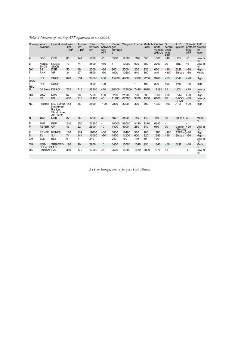
Table 2 Numbers of existing ATP equipment in use (2004)
Country lnfra owner(s)
Operator(s) Pass -km,X 109
Tonne-km,X 109
Totalnetwork km
% network with ATP
Passenger carriages
Wagons Locos Multiple units
Centralunits=Locos.2xMUs
% central units withATP
ATP system
% trafficprotected byATP
ATPprotectionlevel
A ÖBB ÖBB 80 147 5600 <5 3500 17500 1160 350 1860 <10 LZB <5 Low or nil
B NMBS/SNCB
NMBS/SNCB
73 74 3500 <10 1 13000 930 680 2290 30 TBL <5 Low or nil
DK BS DSB 50 19 2300 >60 900 2300 200 230 660 >90 ZUB >90 HighFI RHK VR 34 97 5800 >30 1000 12600 640 100 840 ~100 Ebicab >50 Mediu
mF Conv
RFF SNCF 670 534 30500 >60 15700 48000 5000 2200 9400 >85 KVB >90 High
FHSL
RFF SNCF 1500 100 -- 400 800 100 TVM 100 High
D DB Netz DB AG 725 715 37500 <10 20300 129000 7440 4870 17180 25 LZB <10 Low or nil
HU MAV MAV 67 66 7700 >30 3200 21900 700 330 1360 >90 EVM >90 HighI FS FS 410 215 16100 40 11900 67700 3100 1500 6100 80 BACC/
SCMT<30 Low or
nilNL ProRail NS, Syntus,
Noordned, Railion, Short Lines, ACTS etc
143 35 2800 -100 2800 3300 300 500 1323 -100 ATB >90 High
N JBV NSB 27 25 4200 30 800 2500 180 140 460 30 Ebicab 30 Medium
PL PKP PKP 210 550 22900 - 10000 96000 4140 1270 6680 - -P REFER CP 43 22 2800 10 1400 4000 280 340 960 30 Convel
(Ebicab)<20 Low or
nilE RENFE RENFE 180 114 11800 >60 3800 18400 980 100 1180 ~100 ASFA (-)>90 HighS BV SJ 74 144 10000 >60 1500 11200 600 320 1240 >90 Ebicab >90 HighCH BLS BLS 5 4 240 - 250 160 110 40 190 - - Low or
nilCH SBB-
CFF-FFSSBB-CFF-FFS
126 96 2900 15 3400 13000 1340 250 1840 >50 ZUB >40 Medium
UK Railtrack >20 380 179 17800 «5 2500 14200 1870 3000 7870 <5 -5 Low or nil
ATP in Europe, source Jacques Poré, Alstom