INTERIM DRAFT EUROPEAN TELECOMMUNICATION March 1997 … · Draft prI-ETS 300 837: March 1997 ... of...
44
INTERIM DRAFT EUROPEAN pr I-ETS 300 837 TELECOMMUNICATION March 1997 STANDARD Source: ETSI TC-TE Reference: DI/MTA-004033 ICS: 33.020 Key words: Coding, multimedia, PSTN Public Switched Telephone Network (PSTN); Terminals for low bit-rate Multimedia communication ETSI European Telecommunications Standards Institute ETSI Secretariat Postal address: F-06921 Sophia Antipolis CEDEX - FRANCE Office address: 650 Route des Lucioles - Sophia Antipolis - Valbonne - FRANCE X.400: c=fr, a=atlas, p=etsi, s=secretariat - Internet: [email protected] Tel.: +33 4 92 94 42 00 - Fax: +33 4 93 65 47 16 Copyright Notification: No part may be reproduced except as authorized by written permission. The copyright and the foregoing restriction extend to reproduction in all media. © European Telecommunications Standards Institute 1997. All rights reserved.
Transcript of INTERIM DRAFT EUROPEAN TELECOMMUNICATION March 1997 … · Draft prI-ETS 300 837: March 1997 ... of...

INTERIM DRAFT
EUROPEAN pr I-ETS 300 837
TELECOMMUNICATION March 1997
STANDARD
Source: ETSI TC-TE Reference: DI/MTA-004033
ICS: 33.020
Key words: Coding, multimedia, PSTN
Public Switched Telephone Network (PSTN);Terminals for low bit-rate Multimedia communication
ETSI
European Telecommunications Standards Institute
ETSI Secretariat
Postal address: F-06921 Sophia Antipolis CEDEX - FRANCEOffice address: 650 Route des Lucioles - Sophia Antipolis - Valbonne - FRANCEX.400: c=fr, a=atlas, p=etsi, s=secretariat - Internet: [email protected]
Tel.: +33 4 92 94 42 00 - Fax: +33 4 93 65 47 16
Copyright Notification: No part may be reproduced except as authorized by written permission. The copyright and theforegoing restriction extend to reproduction in all media.
© European Telecommunications Standards Institute 1997. All rights reserved.

Page 2Draft prI-ETS 300 837: March 1997
Whilst every care has been taken in the preparation and publication of this document, errors in content,typographical or otherwise, may occur. If you have comments concerning its accuracy, please write to"ETSI Editing and Committee Support Dept." at the address shown on the title page.

Page 3Draft prI-ETS 300 837: March 1997
Contents
Foreword .......................................................................................................................................................7
Introduction....................................................................................................................................................7
1 Scope ..................................................................................................................................................91.1 Block diagram and functional elements...............................................................................91.2 System elements outside the scope of this I-ETS ...............................................................91.3 Functional elements covered by this I-ETS .......................................................................10
2 Normative references........................................................................................................................11
3 Definitions and abbreviations ............................................................................................................123.1 Definitions ..........................................................................................................................123.2 Abbreviations .....................................................................................................................133.3 Conventions .......................................................................................................................14
4 Functional requirements....................................................................................................................144.1 Required elements.............................................................................................................144.2 Information streams...........................................................................................................154.3 Modem...............................................................................................................................154.4 Multiplexing ........................................................................................................................15
4.4.1 Logical channel numbers ..............................................................................154.4.2 Multiplex table entries....................................................................................164.4.3 Flow control ...................................................................................................164.4.4 Error control...................................................................................................164.4.5 Adaptation layers...........................................................................................16
4.5 Control channel..................................................................................................................164.5.1 Capabilities exchange ...................................................................................174.5.2 Logical channel signaling ..............................................................................184.5.3 Mode preferences .........................................................................................194.5.4 Interface to multiplex .....................................................................................194.5.5 Timer and counter values and protocol errors ..............................................19
4.6 Video channels ..................................................................................................................194.6.1 Interface to multiplex .....................................................................................20
4.7 Audio channels ..................................................................................................................214.7.1 Delay compensation......................................................................................214.7.2 Maximum delay jitter .....................................................................................224.7.3 Interface to multiplexer ..................................................................................22
4.8 Data channels ....................................................................................................................224.8.1 Data protocols ...............................................................................................23
4.8.1.1 Buffered ITU-T Recommendation V.14 ...............................244.8.1.2 LAPM/ITU-T Recommendation V.42...................................244.8.1.3 HDLC frame tunneling .........................................................254.8.1.4 Transparent data .................................................................25
4.8.2 Data applications...........................................................................................254.8.2.1 ITU-T Recommendation T.120 multimedia
teleconferencing applications ..............................................264.8.2.2 ITU-T Recommendation T.84 (SPIFF) point-to-point still
image transfer cutting across application borders...............264.8.2.3 ITU-T Recommendation T.434 point-to-point telematic file
transfer cutting across application borders..........................274.8.2.4 ITU-T Recommendation H.224 real-time control protocol,
for ITU-T Recommendation H.281 far-end camera control.274.8.2.5 Network link layer ................................................................274.8.2.6 External data ports and unspecified user data ....................27

Page 4Draft prI-ETS 300 837: March 1997
5 Terminal procedures......................................................................................................................... 285.1 Phase A - call set-up of voiceband channel ...................................................................... 285.2 Phase B - initial analogue telephony communication........................................................ 28
5.2.1 ITU-T Recommendation V.8 [10] procedure ................................................ 285.2.2 ITU-T Recommendation V.8bis procedure................................................... 28
5.3 Phase C - establishment of digital communication, modem training ................................ 285.3.1 ITU-T Recommendation V.8 [10] procedure ................................................ 285.3.2 ITU-T Recommendation V.8bis procedure................................................... 29
5.4 Phase D - initialization....................................................................................................... 295.4.1 Exchange of video by mutual agreement ..................................................... 30
5.5 Phase E - communication ................................................................................................. 305.5.1 Rate changes and retrains............................................................................ 305.5.2 Involuntary disconnection ............................................................................. 30
5.6 Phase F - end of session .................................................................................................. 305.7 Phase G - change of communication mode and call clearing........................................... 30
6 Interoperation with other terminals ................................................................................................... 316.1 Speech only terminals ....................................................................................................... 316.2 ETS 300 145 multimedia telephone terminals attached to the ISDN................................ 316.3 Multimedia telephone terminals over mobile radio............................................................ 31
7 Optional enhancements.................................................................................................................... 327.1 Data facilities ..................................................................................................................... 327.2 Encryption ......................................................................................................................... 32
7.2.1 EncryptionSE messages............................................................................... 327.2.2 EIV channel .................................................................................................. 327.2.3 Encryption procedure.................................................................................... 337.2.4 Encryption initialization vectors..................................................................... 337.2.5 Error recovery ............................................................................................... 34
7.3 Multilink ............................................................................................................................. 34
8 Multipoint considerations .................................................................................................................. 348.1 Establishment of common mode....................................................................................... 348.2 Multipoint rate matching .................................................................................................... 348.3 Multipoint lip synchronization............................................................................................. 358.4 Multipoint encryption.......................................................................................................... 358.5 Cascaded MCU operation................................................................................................. 35
9 Maintenance ..................................................................................................................................... 359.1 Loopbacks for maintenance purposes .............................................................................. 35
9.1.1 Normal mode ................................................................................................ 359.1.2 System loopback .......................................................................................... 359.1.3 Media loopback............................................................................................. 359.1.4 Logical channel loopback ............................................................................. 35
Annex A (normative): Protocol stack for control channel...................................................................... 37
A.1 General ............................................................................................................................................. 37
A.2 SRP mode ........................................................................................................................................ 38A.2.1 SRP command frames...................................................................................................... 38A.2.2 SRP response frames....................................................................................................... 38A.2.3 SRP procedure at transmitter............................................................................................ 38A.2.4 SRP procedure at receiver ................................................................................................ 39
A.3 LAPM/ITU-T Recommendation V.42 mode...................................................................................... 39
Annex B (normative): HDLC Frame structure transparency for asynchronous transmission............... 40

Page 5Draft prI-ETS 300 837: March 1997
Annex C (informative): Bit and octet order ..............................................................................................41
Annex D (informative): ITU-T Recommendation V.8bis codepoints .......................................................42
Annex E (informative): Bibliography........................................................................................................43
History..........................................................................................................................................................44

Page 6Draft prI-ETS 300 837: March 1997
Blank page

Page 7Draft prI-ETS 300 837: March 1997
Foreword
This draft Interim European Telecommunication Standard (I-ETS) has been produced by the TerminalEquipment (TE) Technical Committee of the European Telecommunications Standards Institute (ETSI),and is now submitted for the Public Enquiry phase of the ETSI standards approval procedure.
An ETSI standard may be given I-ETS status either because it is regarded as a provisional solution aheadof a more advanced standard, or because it is immature and requires a "trial period". The life of an I-ETSis limited to three years after which it can be converted into an ETS, have it's life extended for a furthertwo years, be replaced by a new version, or be withdrawn.
Proposed announcement date
Date of latest announcement of this I-ETS (doa): 3 months after ETSI publication
Introduction
This I-ETS describes terminals for low bit-rate multimedia communication, utilizing ITU-TRecommendation V.34 [15] modems connected to the Public Switched Telephone Network (PSTN). Theterminals described in this I-ETS may carry real-time voice, data, and video, or any combination, includingvideotelephony.
Terminals described in this I-ETS may be integrated into personal computers or implemented instand-alone devices such as videotelephones. Support for each media type (voice, data, video) isoptional, but if supported, the ability to use a specified common mode of operation is required, so that allterminals supporting that media type can interwork. This I-ETS allows more than one channel of each typeto be in use. ITU-T Recommendations relating to the present document are: H.223 [1], H.245 [2],H.263 [4], and G.723.1 [3].
This I-ETS makes use of the logical channel signaling procedures of ITU-T Recommendation H.245 [2], inwhich the content of each logical channel is described when the channel is opened. Procedures areprovided for expression of receiver and transmitter capabilities, so transmissions are limited to whatreceivers can decode, and so that receivers may request a particular desired mode from transmitters.Since the procedures of ITU-T Recommendation H.245 [2] are also planned for use by ITU-TRecommendation H.310 (see annex E) for ATM networks, and ITU-T Recommendation H.323 (seeannex E) for non-guaranteed bandwidth LANs, interworking with these systems should be straightforward.
Terminals described in this I-ETS may be used in multipoint configurations through MCUs, and mayinterwork with ETS 300 145 [22] terminals on the ISDN, as well as with terminals on wireless networks.

Page 8Draft prI-ETS 300 837: March 1997
Blank page
Page 9Draft prI-ETS 300 837: March 1997
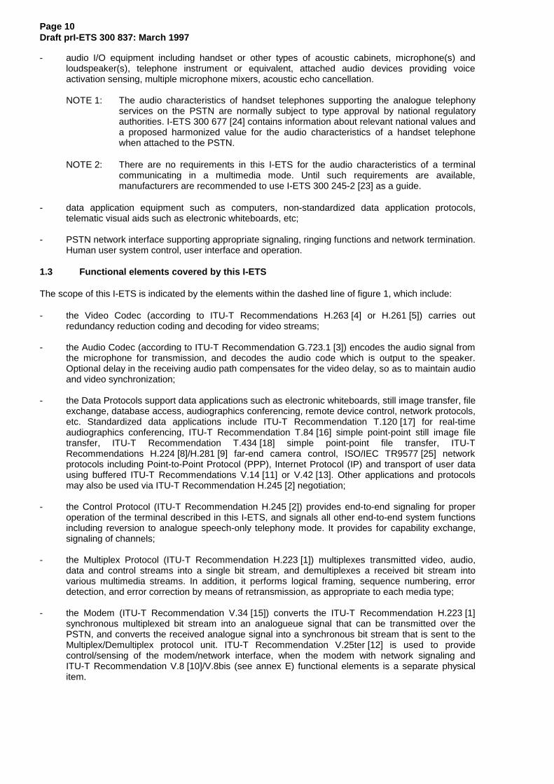
1 Scope
This Interim European Telecommunication Standard (I-ETS) covers the technical requirements for verylow bit-rate multimedia telephone terminals connected to the Public Switched Telephone Network (PSTN).
Interworking with visual telephone systems on the Integrated Services Digital Network (ISDN) (describedin ETS 300 145 [22]) and on mobile radio networks (known as the draft ITU-TRecommendation H.324 [26]/M series of Recommendations) are also covered.
Terminals described in this I-ETS provide real-time video, audio, or data, or any combination, between twomultimedia telephone terminals over a PSTN voice band network connection. Communication may beeither 1-way or 2-way. Multipoint communication using a separate Multipoint Control Unit (MCU) amongmore than two terminals described in this I-ETS is possible. MCUs and other non-terminal devices are notbound by the requirements in this I-ETS, but they should comply where practical.
The multimedia telephone terminals defined in this I-ETS can be integrated into PCs or workstations, orbe stand-alone units.
Control protocolITU-T Rec.H.245 [2]
Scope of this I-ETS
System control
User dataapplicationsT 120 t
Audio I/O equipment
Video I/O equipment
Video codecITU-T Recs.
H.263/H.261 [4,5]
Audio codecITU-T Rec.G.723.1 [3]
Data protocolsITU-T Rec. V.14[11], LAPM, etc.
Receivepath delay
ModemITU-T Rec.V.34/V.8[15, 10]
Multiplex/DemultiplexITU-T Rec.H.223 [1]
Modemcontrol
ITU-T Rec.V.25ter
[12]
Network
MCU
SRP/LAPMprocedures
OptionalITU-TRecs.V.34/V.8bis
[15, 29]
Figure 1: Block diagram of generic multimedia videophone system
1.1 Block diagram and functional elements
A generic multimedia videophone system is shown in figure 1. It consists of terminal equipment, a PSTNmodem, PSTN network, MCU and other system operational entities. Implementations complying with thisI-ETS are not required to have each functional element.
NOTE: Functions for interworking with a normal telephone are not depicted. The support ofsuch a function is described in subclause 6.1.
1.2 System elements outside the scope of this I-ETS
The following system elements, covered by other ETSI (I-)ETSs and ITU-T Recommendations, are notsubject to standardization, or are for other reasons outside the scope of this I-ETS:
- video I/O equipment including cameras and monitors, their control and selection, video processingto improve compression or provide split-screen functions;
NOTE: In this diagram, Rec. means Recommendation.
Page 10Draft prI-ETS 300 837: March 1997
- audio I/O equipment including handset or other types of acoustic cabinets, microphone(s) andloudspeaker(s), telephone instrument or equivalent, attached audio devices providing voiceactivation sensing, multiple microphone mixers, acoustic echo cancellation.
NOTE 1: The audio characteristics of handset telephones supporting the analogue telephonyservices on the PSTN are normally subject to type approval by national regulatoryauthorities. I-ETS 300 677 [24] contains information about relevant national values anda proposed harmonized value for the audio characteristics of a handset telephonewhen attached to the PSTN.
NOTE 2: There are no requirements in this I-ETS for the audio characteristics of a terminalcommunicating in a multimedia mode. Until such requirements are available,manufacturers are recommended to use I-ETS 300 245-2 [23] as a guide.
- data application equipment such as computers, non-standardized data application protocols,telematic visual aids such as electronic whiteboards, etc;
- PSTN network interface supporting appropriate signaling, ringing functions and network termination.Human user system control, user interface and operation.
1.3 Functional elements covered by this I-ETS
The scope of this I-ETS is indicated by the elements within the dashed line of figure 1, which include:
- the Video Codec (according to ITU-T Recommendations H.263 [4] or H.261 [5]) carries outredundancy reduction coding and decoding for video streams;
- the Audio Codec (according to ITU-T Recommendation G.723.1 [3]) encodes the audio signal fromthe microphone for transmission, and decodes the audio code which is output to the speaker.Optional delay in the receiving audio path compensates for the video delay, so as to maintain audioand video synchronization;
- the Data Protocols support data applications such as electronic whiteboards, still image transfer, fileexchange, database access, audiographics conferencing, remote device control, network protocols,etc. Standardized data applications include ITU-T Recommendation T.120 [17] for real-timeaudiographics conferencing, ITU-T Recommendation T.84 [16] simple point-point still image filetransfer, ITU-T Recommendation T.434 [18] simple point-point file transfer, ITU-TRecommendations H.224 [8]/H.281 [9] far-end camera control, ISO/IEC TR9577 [25] networkprotocols including Point-to-Point Protocol (PPP), Internet Protocol (IP) and transport of user datausing buffered ITU-T Recommendations V.14 [11] or V.42 [13]. Other applications and protocolsmay also be used via ITU-T Recommendation H.245 [2] negotiation;
- the Control Protocol (ITU-T Recommendation H.245 [2]) provides end-to-end signaling for properoperation of the terminal described in this I-ETS, and signals all other end-to-end system functionsincluding reversion to analogue speech-only telephony mode. It provides for capability exchange,signaling of channels;
- the Multiplex Protocol (ITU-T Recommendation H.223 [1]) multiplexes transmitted video, audio,data and control streams into a single bit stream, and demultiplexes a received bit stream intovarious multimedia streams. In addition, it performs logical framing, sequence numbering, errordetection, and error correction by means of retransmission, as appropriate to each media type;
- the Modem (ITU-T Recommendation V.34 [15]) converts the ITU-T Recommendation H.223 [1]synchronous multiplexed bit stream into an analogueue signal that can be transmitted over thePSTN, and converts the received analogue signal into a synchronous bit stream that is sent to theMultiplex/Demultiplex protocol unit. ITU-T Recommendation V.25ter [12] is used to providecontrol/sensing of the modem/network interface, when the modem with network signaling andITU-T Recommendation V.8 [10]/V.8bis (see annex E) functional elements is a separate physicalitem.

Page 11Draft prI-ETS 300 837: March 1997
2 Normative references
This I-ETS incorporates by dated and undated reference, provisions from other publications. Thesenormative references are cited at the appropriate places in the text and the publications are listedhereafter. For dated references, subsequent amendments to or revisions of any of these publicationsapply to this I-ETS only when incorporated in it by amendment or revision. For undated references thelatest edition of the publication referred to applies.
[1] ITU-T Recommendation H.223 (1995): "Multiplex protocol for low bit-ratemultimedia communication".
[2] ITU-T Recommendation H.245 (1995): "Control protocol for multimediacommunication".
[3] ITU-T Recommendation G.723.1 (1995): "Dual rate speech coder for multimediacommunication transmitting at 5.3 and 6.3 kbit/s".
[4] ITU-T Recommendation H.263 (1995): "Video coding for low bit-ratecommunication".
[5] ITU-T Recommendation H.261 (1993): "Video codec for audiovisual services atp x 64 kbit/s".
[6] ITU-T Recommendation H.233 (1994): "Confidentiality system for audiovisualservices".
[7] ITU-T Recommendation H.234 (1994): "Encryption key management andauthentication system for audiovisual services".
[8] ITU-T Recommendation H.224 (1994): "A real time control protocol for simplexapplications using the H.221 LSD/HSD/MLP channels".
[9] ITU-T Recommendation H.281 (1994): "A far end camera control protocol forvideoconferences using H.224".
[10] ITU-T Recommendation V.8 (1994): "Procedures for starting sessions of datatransmission over the general switched telephone network".
[11] ITU-T Recommendation V.14 (1993): "Transmission of start-stop charactersover synchronous bearer channels".
[12] ITU-T Recommendation V.25ter (1995): "Serial asynchronous automatic diallingand control".
[13] ITU-T Recommendation V.42 (1993): "Error-correcting procedures for DCEsusing asynchronous-to-synchronous conversion".
[14] ITU-T Recommendation V.42bis (1990): "Data compression procedures fordata-circuit terminating equipment (DCE) using error correction procedures".
[15] ITU-T Recommendation V.34 (1994): "A modem operating at data signalingrates of up to 28 800 bit/s for use on the general switched telephone networkand on leased point-to-point 2-wire telephone-type circuits".
[16] Draft ITU-T Recommendation T.84/ISO/IEC 10918-3 (1996): "Informationtechnology - Digital compression and coding of continuous tone still images -Extensions".
[17] ITU-T Recommendation T.120 (1996): "Data protocols for multimediaconferencing".

Page 12Draft prI-ETS 300 837: March 1997
[18] ITU-T Recommendation T.434 (1992): "Binary file transfer format for thetelematic services".
[19] ISO/IEC 3309 (1991): "Information Technology - Telecommunications andinformation exchange between systems - High-level data link control (HDLC)procedures - Frame structure".
[20] ITU-T Recommendation G.711 (1988): "Pulse code modulation (PCM) of voicefrequencies".
[21] ETS 300 144: "Integrated Services Digital Network (ISDN); Audiovisual services;Frame structure for a 64 kbit/s to 1 920 kbit/s channel and associated syntax forinband signalling".
[22] ETS 300 145 (1994): "Integrated Services Digital Network (ISDN); Audiovisualservices; Videotelephone systems and terminal equipment operating on one ortwo 64 kbit/s channels".
[23] I-ETS 300 245-2 (1994): "Integrated Services Digital Network (ISDN); Technicalcharacteristics of telephony terminals; Part 2: PCM A-law handset telephony".
[24] I-ETS 300 677 (1996): "Public Switched Telephone Network (PSTN);Requirements for handset telephony".
[25] ISO/IEC TR9577 (1990): "Information Technology - protocol identification in thenetwork layer".
[26] ITU-T Recommendation H.324 (1996): "Terminal for low bit rate multimediacommunication".
[27] ITU-T Recommendation V.24 (1993): "List of definitions for interchange circuitsbetween data terminal equipment (DTE) and data circuit-terminating equipment(DCE)".
[28] ITU-T Recommendation T.123 (1994): "Protocol stacks for audiographic andaudiovisual teleconference applications".
3 Definitions and abbreviations
3.1 Definitions
For the purposes of this I-ETS, the definitions given in clause 3 of both ITU-T Recommendations H.223 [1]and H.245 [2] apply, along with the following:
AL-SDU: The logical unit of information exchanged between the ITU-T Recommendation H.223 [1]multiplexer and the audio Codec, video Codec, or data protocol.
channel: A unidirectional link between two end-points.
CODEC: A coder/decoder, used to convert audio or video signals to/from digital format.
connection: A bi-directional link between two end-points.
control channel: Dedicated logical channel number 0 carrying system control protocol per ITU-TRecommendation H.245 [2].
data: Information streams other than control, audio and video, carried in a logical data channel (see ITU-TRecommendation H.223 [1]).
in-band signaling: Control signals sent within a specific logical channel other than the control channel,carrying information applicable only to that logical channel.

Page 13Draft prI-ETS 300 837: March 1997
interworking adapter: A device connected to terminals or MCUs working according to two or moreRecommendations, which translates the content of one or more logical channels to allow interoperationbetween otherwise incompatible equipment.
LAPM/V.42: The link access procedures that are used in ITU-T Recommendation V.42 [13].
lip synchronization: Operation to provide the impression that speaking motion of the displayed person issynchronized with the voice sounds.
logical channel: One of several logically distinct channels carried over a single bit-stream.
media: One or more of audio, video, or data.
multilink: The use of more than one physical connection to obtain a larger aggregate bit-rate.
multipoint: The simultaneous interconnection of three or more terminals to allow communication amongseveral sites through the use of multipoint control units (bridges) which centrally direct the flow ofinformation.
MUX-PDU: The logical unit of information exchanged between the ITU-T Recommendation H.223 [1]multiplex layer and the underlying physical layer. It is a packet framed by High-level Data Link Control(HDLC) flags and using HDLC zero-bit insertion for transparency.
non-segmentable: The ITU-T Recommendation H.223 [1] mode of operation in which AL-SDUs need tobe sent as consecutive octets in a single MUX-PDU. See Recommendation H.223 [1].
segmentable: The ITU-T Recommendation H.223 [1] mode of operation in which AL-SDUs may be sentin separate multiplex slots carried on one or more MUX-PDUs (see ITU-T Recommendation H.223 [1]).
support: The ability to operate in a given mode, however a requirement to "support" a mode does notmean that the mode must actually be used at all times. Unless prohibited, other modes may be used bymutual negotiation.
videophone: A terminal capable of sending and receiving audio and video information simultaneously.
3.2 Abbreviations
For the purposes of this I-ETS, the following abbreviations apply.
AL Adaptation Layer (see ITU-T Recommendation H.223 [1])BAS Bit-rate Allocation SignalBCH Bose, Chaudhuri, HocquenghamCIF Common Intermediate FormatCRC Cyclic Redundancy CheckC/R Command Response bitCM Call Menu signalDCE Data Communication EquipmentDLCI Data Link Connection IdentifierDTE Data Terminal EquipmentEA Address field ExtensionECS Encryption Control SignalEIV Encryption Initialization VectorFAS Frame Aligment SignalFCS Frame Check SequenceHDLC High-level Data Link Control (ISO/IEC 3309 [19])IETF Internet Engineering Task ForceIP Internet ProtocolISDN Integrated Services Digital NetworkIV Initialization VectorJBIG Joint Bi-level Image experts GroupJM Joint Menu signalLAPM Link Access Procedures for Modems (ITU-T Recommendation V.42 [13])

Page 14Draft prI-ETS 300 837: March 1997
LCN Logical Channel Number (ITU-T Recommendation H.223 [1])MCU Multipoint Control UnitMUX MultiplexNLPID Network Layer Protocol Identifier (ISO/IEC TR9577 [25])PDU Protocol Data UnitPPP Point-to-Point ProtocolPSTN Public Switched Telephone NetworkQCIF Quarter CIFSDU Service Data Unit (ITU-T Recommendation H.223 [1])SE Session Exchange (ITU-T Recommendation H.233 [6])SQCIF Sub QCIFSPIFF Still Picture Interchange File FormatSRP Simple Retransmission Protocol (see annex A)XID eXchange IDentification
3.3 Conventions
The word "shall" is used in this I-ETS to specify a mandatory requirement.
The word "should" is used in this I-ETS to specify a suggested, but not required, course of action.
The word "may" is used in this I-ETS to specify an optional course of action, without expressing apreference.
References in this I-ETS to specific ITU-T Recommendation H.245 [2] message structures are presentedin this typeface .
4 Functional requirements
4.1 Required elements
Implementations of this I-ETS are not required to have each functional element, except for the ITU-TRecommendation V.34 [15] modem, ITU-T Recommendation H.223 [1] multiplex, and ITU-TRecommendation H.245 [2] system control protocol, all of which shall be supported by all terminalscomplying with this I-ETS.
Terminals complying with this I-ETS and offering audio communication shall support the ITU-TRecommendation G.723.1 [3] audio Codec. Likewise, the same terminals offering video communicationshall support the ITU-T Recommendations H.263 [4] and H.261 [5] video Codecs. Terminals complyingwith this I-ETS and offering real-time audiographic conferencing should support the ITU-TRecommendation T.120 [17] protocol suite. In addition, other video and audio Codecs, and other dataprotocols, may optionally be used via negotiation over the ITU-T Recommendation H.245 [2] controlchannel.
If a modem external to a terminal compliant with this I-ETS is used, terminal/modem control shall conformto ITU-T Recommendation V.25ter [12].
The presence of optional facilities is signalled via the ITU-T Recommendation H.245 [2] control channel. Ifboth ends support an optional facility, and choose to make use of it, the opening of a path to carry suchinformation streams is negotiated according to the procedures of ITU-T recommendation H.245 [2].
NOTE: This I-ETS does not specify a particular implementation. Any implementation thatprovides the required functionality, and that conforms to the bit-stream formatultimately described by this I-ETS, is considered compliant.

Page 15Draft prI-ETS 300 837: March 1997
4.2 Information streams
Multimedia information streams are classified into video, audio, data, and control as follows:
- video streams are continuous traffic carrying moving color pictures. When used, the bit-rateavailable for video streams may vary according to the needs of the audio and data channels;
- audio streams are real-time, but may optionally be delayed in the receiver processing path tomaintain synchronization with the video streams. In order to reduce the average bit-rate of audiostreams, voice activation may be provided;
- data streams may represent still pictures, facsimile, documents, computer files, computerapplication data, undefined user data, and other data streams;
- control streams pass control commands and indications between remote counterparts.Terminal-to-modem control conforms to ITU-T Recommendation V.25ter [12] for terminals usingexternal modems connected by a separate physical interface. Terminal-to-terminal control isaccording to ITU-T Recommendation H.245 [2].
4.3 Modem
Modems used as terminals compliant with this I-ETS shall operate in full duplex, synchronous mode andconform to ITU-T Recommendations V.34 [15] and V.8 [10]. Support of ITU-T Recommendation V.8bis(see annex E) is optional. The output of the ITU-T Recommendation H.223 [1] multiplexer shall be applieddirectly to the ITU-T Recommendation V.34 [15] synchronous data pump. When an external, non-integrated ITU-T Recommendation V.34 [15] modem is used, control between the modem and theterminal shall be via ITU-T Recommendation V.25ter [12]. In such cases the physical interface isimplementation specific.
The use of the optional ITU-T Recommendation V.34 [15] auxiliary channel is reserved for further study.
4.4 Multiplexing
Logical channels of video, audio, data or control information may be transmitted, after the channels havebeen established according to the procedures of ITU-T Recommendation H.245 [2]. Logical channels areunidirectional, and are independent in each direction of transmission. Any number of logical channels ofeach media type may be transmitted, except for the ITU-T Recommendation H.245 [2] control channel ofwhich there shall be one. The multiplexing method used to transmit these logical channels shall conformto ITU-T Recommendation H.223 [1]. The optional exclusive-OR procedure in section 6.4.2 of ITU-TRecommendation H.223 [1] shall not be used by terminals compliant with this I-ETS.
The ITU-T Recommendation H.223 [1] multiplexer consists of a multiplex layer, which mixes the variouslogical channels into a single bit-stream, and an adaptation layer, which handles error control andsequence numbering, as appropriate to each information stream. The multiplex layer transfers logicalchannel information in packets called Multiplexer-Protocol Data Units (MUX-PDU)s, delimited by HDLCflags and using HDLC zero-bit insertion for transparency. Each MUX-PDU contains a one-byte headerfollowed by a variable number of information field bytes. The header byte includes a multiplexing code,which specifies, by reference to a multiplex table, the mapping of the information field bytes to variouslogical channels. Each MUX-PDU may contain a different multiplex code, and therefore a different mix oflogical channels.
I-ETS compliant terminals shall signal their ITU-T Recommendation H.223 [1] capabilities via theH223Capability message.
4.4.1 Logical channel numbers
Each logical channel is identified by a Logical Channel Number (LCN), in the range 0 to 65 535, whichserves merely to associate logical channels with the corresponding entries in the ITU-TRecommendation H.223 [1] multiplex table. Logical channel numbers are selected arbitrarily by thetransmitter, except that logical channel 0 shall be permanently assigned to the ITU-TRecommendation H.245 [2] control channel.

Page 16Draft prI-ETS 300 837: March 1997
4.4.2 Multiplex table entries
Multiplex table entries are independent in each direction of transmission, and are sent from transmitters toreceivers using the MultiplexEntrySend request message. Multiplex table entry 0 shall not sent, but shallbe permanently assigned to logical channel 0, used for the control channel. Multiplex table entry 0 shalltherefore be used for initial capability exchanges and transmission of initial multiplex table entries.
4.4.3 Flow control
Terminals compliant with this I-ETS shall respond to the FlowControlCommand message, whichcommands a limit to the overall bit rate of one or more logical channels, or the entire multiplexer.
When one or more logical channels are limited by the FlowControlCommand , other less restricted logicalchannels may increase their transmission rate. The limit applies to the content of the logical channel at theinput to the multiplexer layer, before flags or zero-bit insertion are applied.
When the entire ITU-T Recommendation H.223 [1] multiplexer is limited by the FlowControlCommand , orwhen the terminal has no information to send, the terminal shall send HDLC flags in place of logicalchannel information. The limit applies to the entire multiplex output, including opening flags, header bytes,and inserted zero bits, but not including idle flags.
4.4.4 Error control
The multiplex layer of ITU-T Recommendation H.223 [1] does not perform error control, except for aCyclic Redundancy Check (CRC) on the header byte. Error control for each logical channel is handledseparately by the adaptation layers of ITU-T Recommendation H.223 [1], which may use a variety of errorcontrol techniques, including but not limited to error detection and retransmission.
4.4.5 Adaptation layers
ITU-T Recommendation H.223 [1] defines three Adaptation Layers (AL), AL1, AL2, and AL3. AL1 isintended primarily for variable-rate framed information, including unframed bytes treated as a single frameof indefinite length. AL2 is intended primarily for digital audio, and includes an 8-bit CRC and optionalsequence numbers. AL3 is intended primarily for digital video and includes provision for retransmission.
The logical unit of information exchanged between the ITU-T Recommendation H.223 [1] multiplexer andthe audio Codec, video Codec, data protocol, or control protocol is called an Adaptation Layer-ServiceData Unit (AL-SDU).
Logical channels carried by the ITU-T Recommendation H.223 [1] multiplexer may be of either"segmentable" or "non-segmentable" type, as defined in ITU-T Recommendation H.223 [1], and signalledby ITU-T Recommendation H.245 [2] when each channel is opened. AL-SDUs of segmentable logicalchannels may be segmented by the ITU-T Recommendation H.223 [1] multiplexer. AL-SDUs of non-segmentable logical channels are not segmented by the ITU-T Recommendation H.223 [1] multiplexer.Generally, segmentable channels should be used for variable bit-rate information streams such as control,video, and data, while non-segmentable channels should be used for constant bit-rate streams such asaudio.
Receivers shall signal their capability to process various adaptation layers and channel types according toITU-T Recommendation H.245 [2]. Transmitters shall signal which adaptation layers, options, and channeltype are used for each logical channel when opening the channel, according to ITU-TRecommendation H.245 [2].
4.5 Control channel
The control channel carries end-to-end control messages governing operation of the MultimediaVideophone system, including capabilities exchange, opening and closing of logical channels, modepreference requests, multiplex table entry transmission, flow control messages, and general commandsand indications.

Page 17Draft prI-ETS 300 837: March 1997
There shall be exactly one control channel in each direction within systems complying with this I-ETS,which shall use the messages and procedures of ITU-T Recommendation H.245 [2]. The control channelshall be carried on logical channel 0. The control channel shall be considered to be permanently openfrom the establishment of digital communication until the termination of digital communication; the normalprocedures for opening and closing logical channels shall not apply to the control channel.
General commands and indications shall be chosen from the message set contained in ITU-TRecommendation H.245 [2]. In addition other command and indication signals may be sent which havebeen specifically defined to be transferred in-band within video, audio or data streams (see theappropriate Recommendation to determine if such signals have been defined).
ITU-T Recommendation H.245 [2] messages fall into four categories: Request, Response, Command,and Indication. Request messages require a specific action by the receiver, including an immediateresponse. Response messages respond to a corresponding request. Command messages require aspecific action, but do not require a response. Indication messages are informative only, and do notrequire any action or response. Terminals compliant with this I-ETS shall respond to all supportedcommands and requests as specified in ITU-T Recommendation H.245 [2], and shall transmit accurateindications reflecting the state of the terminal.
NOTE: All control channel messages are sent over a link layer protocol which acknowledgescorrect receipt. This acknowledgment is distinct from the response messages, whichconvey content beyond that of correct receipt of the message.
Terminals compliant with this I-ETS shall be capable of parsing all MultimediaSystemControlPDUmessages, and shall send and receive all messages needed to implement required functions and thoseoptional functions which are supported by the terminal. All messages and procedures of ITU-TRecommendation H.245 [2] related to needed functions compliant with this I-ETS are required, except forthose explicitly described as optional, or which are related to defined optional capabilities the terminaldoes not support. Terminals compliant with this I-ETS shall send the FunctionNotSupported message inresponse to unrecognized request, response, or command messages.
A control channel indication, UserInputIndication , is available for transport of user input alphanumericcharacters from a keypad or keyboard, equivalent to the DTMF signals used in analogue telephony. Thismay be used to manually operate remote equipment such as voice mail or video mail systems, menu-driven information services, etc. Terminals compliant with this I-ETS shall support the transmission of userinput characters "0-9", "*", and "#". Transmission of other characters is optional.
NOTE: If the encryption procedures of this I-ETS are in use, the control channel will not beencrypted. Users are therefore cautioned regarding the carriage of user data in thecontrol channel, the use of non-standard messages and the confidentiality risk fromtraffic analysis of the control channel.
4.5.1 Capabilities exchange
Capabilities exchange shall follow the procedures of ITU-T Recommendation H.245 [2], which provides forseparate receive and transmit capabilities, as well as a system by which the terminal may describe itsability to operate in various combinations of modes simultaneously.
Receive capabilities describe the terminal's ability to receive and process incoming information streams.Transmitters shall limit the content of their transmitted information to that which the receiver has indicatedit is capable of receiving. The absence of a receive capability indicates that the terminal cannot receive(i.e. it is a transmitter only).
Transmit capabilities describe the terminal's ability to transmit information streams. Transmit capabilitiesserve to offer receivers a choice of possible modes of operation, so that the receiver may request themode which it prefers to receive. The absence of a transmit capability indicates that the terminal is notoffering a choice of preferred modes to the receiver (but it may still transmit anything within the capabilityof the receiver).
The transmitting terminal assigns each individual mode the terminal is capable of operating in a number ina capabilityTable . For example, ITU-T Recommendations G.723.1 [3] audio, G.728 (see annex E) audio,and Common Intermediate Format (CIF) and ITU-T Recommendation H.263 [4] video would each beassigned separate numbers.

Page 18Draft prI-ETS 300 837: March 1997
These capability numbers are grouped into AlternativeCapabilitySet structures. EachAlternativeCapabilitySet indicates that the terminal is capable of operating in exactly one mode listed in theset. For example, an AlternativeCapabilitySet listing {ITU-T Recommendations G.711 [20], G.723.1 [3],G.728 (see annex E)} means that the terminal can operate in any one of those audio modes, but not morethan one.
These AlternativeCapabilitySet structures are grouped into simultaneousCapabilities structures. EachsimultaneousCapabilities structure indicates a set of modes the terminal is capable of usingsimultaneously. For example, a simultaneousCapabilities structure containing the twoAlternativeCapabilitySet structures {ITU-T Recommendations H.261 [5], H.263 [4]} and{ITU-T Recommendations G.711 [20], G.723.1 [3], G.728 (see annex E)} means that the terminal canoperate either of the video Codecs simultaneously with any one of the audio Codecs. ThesimultaneousCapabilities set {ITU-T Recommendations {H.261 [5]}, {H.261 [5], H.263 [4]}, {G.711 [20],G.723.1 [3], G.728 (see annex E)}} means the terminal can operate two video channels and one audiochannel simultaneously: One video channel as per ITU-T Recommendation H.261 [5], another videochannel as per either ITU-T Recommendations H.261 [5] or H.263 [4], and one audio channel as pereither ITU-T Recommendations G.711 [20], G.723.1 [3], G.728 (see annex E).
NOTE: The actual capabilities stored in the capabilityTable are often more complex thanpresented here. For example, each ITU-T Recommendation H.263 [4] capabilityindicates details including ability to support various picture formats at given minimumpicture intervals, and ability to use optional coding modes. For a complete description,see ITU-T Recommendation H.245 [2].
The terminal’s total capabilities are described by a set of CapabilityDescriptor structures, each of which isa single simultaneousCapabilities structure and a capabilityDescriptorNumber . By sending more than oneCapabilityDescriptor , the terminal may signal dependencies between operating modes by describingdifferent sets of modes which it can simultaneously use. For example, a terminal issuing twoCapabilityDescriptor structures, one {ITU-T Recommendations {H.261 [5], H.263 [4]}, {G.711 [20],G.723.1 [3], G.728 see annex E}} as in the previous example, and the other {ITU-T Recommendations{H.262 see annex E}, {G.711 [20]}}, means the terminal can also operate the ITU-T RecommendationH.261 [5] video Codec, but only with the low-complexity ITU-T Recommendation G.711 [20] audio Codec.
Terminals may dynamically add capabilities during a communication session by issuing additionalCapabilityDescriptor structures, or remove capabilities by sending revised CapabilityDescriptor structures.All terminals compliant with this I-ETS shall transmit at least one CapabilityDescriptor structure.
Non-standard capabilities and control messages may be issued using the NonStandardParameterstructure. Note that while the meaning of non-standard messages is defined by individual organizations,equipment built by any manufacturer may signal any non-standard message, if the meaning is known.
Terminals may re-issue capability sets at any time, according to the procedures of ITU-TRecommendation H.245 [2].
4.5.2 Logical channel signaling
Each logical channel carries information from a transmitter to a receiver, and is identified by a logicalchannel number unique for each direction of transmission.
Logical channels are opened and closed using the OpenLogicalChannel and CloseLogicalChannelmessages and procedures of ITU-T Recommendation H.245 [2]. When a logical channel is opened, theOpenLogicalChannel message fully describes the content of the logical channel, including media type,algorithm in use, ITU-T Recommendation H.223 [1] adaptation layer and any options, and all otherinformation needed for the receiver to interpret the content of the logical channel. Logical channels may beclosed when no longer needed. Open logical channels may be inactive, if the information source hasnothing to send.
Logical channels described in this I-ETS are unidirectional. Asymmetrical operation therefore, in which thenumber and type of information streams is different in each direction of transmission, is allowed. However,if a receiver is capable only of certain symmetrical modes of operation, it may send a receive capability setthat reflects its limitations. Terminals may also be capable of using a particular mode in only one directionof transmission.

Page 19Draft prI-ETS 300 837: March 1997
Certain media types, including data protocols such as ITU-T Recommendation T.120 [17] and LinkAccess Procedures for Modems (LAPM), and video carried over AL3, inherently require a bi-directionalchannel for their operation. In such cases a pair of unidirectional logical channels, one in each direction,may be opened and associated together to form a bi-directional channel using the bi-directional channelopening procedures of ITU-T Recommendation H.245 [2]. Such pairs of associated channels need notshare the same logical channel number, since logical channel numbers are independent in each directionof transmission.
4.5.3 Mode preferences
Receivers may request transmitters to send a particular mode using the RequestMode message, whichdescribes the desired mode. When in receipt of multipointModeCommand transmitters shall comply withsuch request. In other modes transmitters may deny such requests, but should comply if possible.
4.5.4 Interface to multiplex
The control channel shall be segmentable and use logical channel 0. All terminals compliant with thisI-ETS shall support transmission of ITU-T Recommendation H.245 [2] control messages over the framedAL1 layer of ITU-T Recommendation H.223 [1] according to the procedures in annex A, which ensurereliable delivery by retransmission of errored frames.
Annex A defines a Simple Retransmission Protocol (SRP) as a data link layer for H.245. All terminalsdescribed in this I-ETS shall support the SRP defined in annex A. Terminals may optionally useLAPM/ITU-T Recommendation V.42 [13] as a data link layer instead of the SRP, if this mode is negotiatedas per the procedure in annex A. In the LAPM/ITU-T Recommendation V.42 [13] mode several controlmessages may be streamed using the procedures of LAPM, avoiding a wait for acknowledgment of eachframe before the next message may be sent.
More than one ITU-T Recommendation H.245 [2] control message may be sent in each SRP or LAPMframe.
4.5.5 Timer and counter values and protocol errors
All timers defined in ITU-T Recommendation H.245 [2] shall have periods of at least the maximum datadelivery time allowed by the data link layer carrying ITU-T Recommendation H.245 [2], including anyretransmissions. For SRP, this shall be a period of at least T401 x N400 (acknowledgmenttimer x retransmit counter).
The ITU-T Recommendation H.245 [2] retry counter (N100) should be at least 3.
If an ITU-T Recommendation H.245 [2] protocol error occurs, the terminal may optionally retry the ITU-TRecommendation H.245 [2] procedure or may take other appropriate action, such as disconnection orreversion to analogue telephony, depending on predetermined configuration.
4.6 Video channels
All terminals described in this I-ETS which offer video communication shall support both the ITU-TRecommendations H.263 [4] and H.261 [5] video Codecs, except ETS 300 145 [22] Interworking Adapters(which are not terminals) do not have to support ITU-T Recommendation H.263 [4] (see section 6.2). TheITU-T Recommendations H.263 [4] and H.261 [5] Codecs shall be used without Bose, Chaudhuri,Hocquengham (BCH) error correction and without error correction framing. There are five standardizedimage formats: 16CIF, 4CIF, CIF, Quarter Common Intermediate Format (QCIF), and Sub QuarterCommon Intermediate Format (SQCIF). Video may be supported in either one direction (transmit orreceive) or both directions.
CIF and QCIF are defined in ITU-T Recommendation H.261 [5]. For the ITU-T Recommendation H.263 [4]algorithm, SQCIF, 4CIF and 16CIF are defined. For the ITU-T Recommendation H.261 [5] algorithm,SQCIF is any active picture size less than QCIF, filled out by a black border, and coded in the QCIFformat. For all these formats, the pixel aspect ratio is the same as that of the CIF format.
NOTE: The resulting picture aspect ratio for ITU-T Recommendation H.263 [4] SQCIF isdifferent from the other formats.

Page 20Draft prI-ETS 300 837: March 1997
Table 1 shows which picture formats are required, and which are optional for terminals described in thisI-ETS which support video.
Table 1: Picture formats for video terminals
Pictureformat
Luminancepixels
Encoder Decoder
ITU-TRecommendation
H.261 [5]
ITU-TRecommendation
H.263 [4]
ITU-TRecommendation
H.261 [5]
ITU-TRecommendation
H.263 [4]SQCIF 128 x 96 for
ITU-T Rec.H.263 [4] (note 3)
Optional(note 3)
Required(notes 1 and 2)
Optional(note 3)
Required(note 1)
QCIF 176 x 144 Required Required(notes 1 and 2)
Required Required(note 1)
CIF 352 x 288 Optional Optional Optional Optional4CIF 704 x 576 Not defined Optional Not defined Optional16CIF 1408 x 1152 Not defined Optional Not defined Optional
NOTE 1: Optional for ETS 300 145 [22] interworking adapters.NOTE 2: Mandatory to encode one of the picture formats QCIF and SQCIF; optional to encode both
formats.NOTE 3: ITU-T Recommendation H.261 [5] SQCIF is any active size less than QCIF, filled out by a
black border, coded in QCIF format.
All video decoders shall be capable of processing video bitstreams of the maximum bit-rate which can bereceived by the implementation of the ITU-T Recommendation H.223 [1] multiplexer (maximum ITU-TRecommendation V.34 [15] rate for single link, 2 x rate for double link, etc.).
Which picture formats, minimum number of skipped pictures, and algorithm options can be accepted bythe decoder is determined during the capability exchange using ITU-T Recommendation H.245 [2]. Afterthat, the encoder is free to transmit anything which is in line with the decoder's capability. Decoders whichindicate capability for a particular algorithm option shall also be capable of accepting video bit-streamswhich do not make use of that option.
When each video logical channel is opened, the maximum operating mode to be used on that channel issignalled to the receiver. The picture header within the video bit-stream indicates which mode is actuallyused for each picture, within the stated maximum. Receivers may signal, via ITU-TRecommendation H.245 [2], a preference for a certain mode.
NOTE: The maximum mode signalled includes maximum picture format, algorithm options,etc. For example, a video logical channel opened for CIF format may transmit CIF,QCIF, or SQCIF pictures, but not 4CIF or 16CIF. A video logical channel opened withonly the unrestrictedVector and arithmeticCoding options may use neither, either, orboth options, but shall not use options which were not signalled.
Other video Codecs, and other picture formats, may also be used via ITU-T Recommendation H.245 [2]negotiation. More than one video channel may be transmitted, as negotiated via the ITU-TRecommendation H.245 [2] control channel.
NOTE: The method of continuous presence multipoint operation, in which a single picture isdivided into multiple sub-pictures, should not be used by terminals described in thisI-ETS. Instead, multiple logical channels of video should be used.
4.6.1 Interface to multiplex
All terminals described in this I-ETS offering video communication shall support the required video Codecsin segmentable logical channels using ITU-T Recommendation H.223 [1] adaptation layer AL3, and usinga control field of at least one byte. Support of retransmission is required in encoders, with a minimum AL3SendBufferSize of 1 024 bytes.

Page 21Draft prI-ETS 300 837: March 1997
The size of each AL-SDU, and their alignment with the video bit-stream, is determined by video encoders,within the limit of the maximum AL3 SDU size the receiver indicates it is capable of. Video pictures mayspan more than one AL-SDU. ITU-T Recommendation H.261 [5] AL-SDUs are not required to align withlogical structures in the video bit-stream. ITU-T Recommendation H.263 [4] encoders shall align picturestart codes with the start of an AL-SDU.
NOTE: ITU-T Recommendation H.263 [4] pictures are a whole number of bytes in length,since encoders add fill zero bits at the end of each picture as needed to fill out the finalbyte.
If video communication is supported only in one direction (transmit or receive), the ITU-TRecommendation H.223 [1] adaptation layer AL3 protocol for the reverse direction shall also besupported, even if no video information will be sent on the reverse channel. Since the AL3 protocolrequires a reverse channel for operation, logical channels using AL3 shall be opened using the ITU-TRecommendation H.245 [2] procedures for opening associated logical channels in each direction oftransmission (bi-directional channels).
While ITU-T Recommendation H.223 [1] AL3 allows for the retransmission of video information withdetected errors, the receiving terminal may decide not to request a retransmission, based on factorsincluding but not limited to: the measured network delay, the error rate, whether the terminal is part of amultipoint conference, whether there is interworking with a ETS 300 145 [22] terminal, and theeffectiveness of its error concealment techniques.
When a video Codec receives an AL-DRTX indication from an ITU-T Recommendation H.223 [1] AL3,indicating that the local AL3 layer was unable to satisfy a retransmission request, it shall encode the nextvideo picture in the INTRA coding mode.
Other video Codecs, adaptation layers and options may be used via ITU-T Recommendation H.245 [2]negotiation.
4.7 Audio channels
All terminals described in this I-ETS which offer audio communication shall support both the high and lowrates of the ITU-T Recommendation G.723.1 [3] audio Codec. ITU-T Recommendation G.723.1 [3]receivers may optionally be capable of accepting silence frames. The choice of high rate, low rate, orsilence is made by the transmitter, and is signalled to the receiver in-band in the audio channel, as part ofthe syntax of each audio frame. Transmitters may switch G.723.1 [3] rates on a frame-by-frame basis,based on bit-rate, audio quality, or other preferences. Receivers may signal, via ITU-TRecommendation H.245 [2], a preference for a particular audio rate or mode. Audio may be supported ineither one direction (transmit or receive) or both directions.
Alternative audio Codecs may also be used, via ITU-T Recommendation H.245 [2] negotiation. Codersmay omit sending audio signals during silent periods after sending a single frame of silence, or may sendsilence background fill frames if such techniques are specified by the audio Codec Recommendation inuse.
More than one audio channel may be transmitted, as negotiated via the ITU-T Recommendation H.245 [2]control channel.
NOTE: Each audio channel is independent. Grouping of audio channels into stereo pairs orother synchronized groups is for further study.
4.7.1 Delay compensation
The ITU-T Recommendations H.263 [4] and H.261 [5] video Codecs require some processing delay, whilethe ITU-T Recommendation G.723.1 [3] audio Codec involves much less delay. Lip synchronization is notmandatory, but if it is to be maintained, additional delay must be added in the audio path to compensate.Terminals described in this I-ETS shall not add delay for this purpose in the transmitting audio path.Instead, since video and audio coder delays may vary according to implementation, they shall signal, viaH223SkewIndication messages in the control channel, the average skew by which their transmitted videosignal trails the audio signal.

Page 22Draft prI-ETS 300 837: March 1997
Intermediate processing points such as MCUs or interworking adapters may alter the video/audio skew(see subclause 10.3), and shall transmit appropriately modified video/audio skew indications, reflectingtheir transmitted streams. Video signals shall not precede audio signals; if necessary, video path delayshall be added to prevent this.
Receiving terminals may optionally use this information to add appropriate delay in the audio path toachieve lip synchronization.
4.7.2 Maximum delay jitter
Audio AL-SDUs shall be transmitted periodically at an interval determined by the audio CodecRecommendation in use (audio frame interval). The transmission of each audio AL-SDU at the ITU-TRecommendation H.223 [1] multiplexer shall commence no later than 10 ms after a whole multiple of theaudio frame interval, measured from transmission of the first audio frame (audio delay jitter). Transmitterscapable of further limiting their audio delay jitter may so signal using the maximumDelayJitter parameter ofthe H223Capability message, so that receivers may optionally reduce their jitter delay buffers.
4.7.3 Interface to multiplexer
All terminals described by this I-ETS which offer audio communication shall support the ITU-TRecommendation G.723.1 [3] Codec using ITU-T Recommendation H.223 [1] adaptation layer AL2. Theuse of the Sequence Number option of AL2 is optional, but is not recommended for ITU-TRecommendation G.723.1 [3], since sequence numbers are generally not useful when the maximumdelay jitter is less than the audio frame interval.
For all frame-oriented audio Codecs, AL-SDUs shall be transmitted in non-segmentable logical channels.Receivers shall signal the maximum number of audio frames they are capable of accepting in a singleaudio AL-SDU. Transmitters may send any whole number of audio frames in each AL-SDU, up to themaximum stated by the receiver. Transmitters shall not split audio frames across AL-SDUs, and shallsend whole numbers of bytes in each audio AL-SDU.
NOTE: Sample based Codecs, such as ITU-T Recommendation G.711 [20], shall beconsidered to be frame-oriented, with a frame size of one sample.
For audio algorithms such as ITU-T Recommendation G.723.1 [3] which use more than one size of audioframe, audio frame boundaries within each AL-SDU shall be signalled in-band to the audio channel. Foraudio algorithms which use a fixed frame size, audio frame boundaries shall be implied by the ratio ofAL-SDU size to audio frame size.
Other adaptation layers and options may be used via ITU-T Recommendation H.245 [2] negotiation.
NOTE: Transmitters using alternative audio Codecs should also support AL2, unless anotheradaptation layer has been specified for use with a particular Codec.
4.8 Data channels
All data channels are optional. Standardized options for data applications include:
- ITU-T Recommendation T.120 [17] series for point-to-point and multipoint audiographicteleconferencing including database access, still image transfer and annotation, application sharing,real-time file transfer, etc.;
- ITU-T Recommendation T.84 [16] Still Picture Interchange File Format (SPIFF) point-to-point stillimage transfer cutting across application borders;
- ITU-T Recommendation T.434 [18] point-to-point telematic file transfer cutting across applicationborders;
- ITU-T Recommendation H.224 [8] for real-time control of simplex applications, including ITU-TRecommendation H.281 [9] far end camera control;
- network link layer, as per ISO/IEC TR9577 [25] (supports Internet Protocol (IP) and Point-to-PointProtocol (PPP) network layers, among others);

Page 23Draft prI-ETS 300 837: March 1997
- unspecified user data from external data ports.
These data applications may reside in an external computer or other dedicated device attached to theterminal defined by this I-ETS through an ITU-T Recommendation V.24 [27] or equivalent interface(implementation dependent), or may be integrated into the terminal decribed by this I-ETS itself. Eachdata application makes use of an underlying data protocol for link layer transport. For each dataapplication supported by the terminal, this recommendation requires support for a particular underlyingdata protocol to ensure interworking of data applications.
NOTE: The ITU-T Recommendation H.245 [2] control channel is not considered a datachannel.
Standardized link layer data protocols used by data applications include:
- buffered ITU-T Recommendation V.14 [11] mode for transfer of asynchronous characters, withouterror control;
- LAPM/ITU-T Recommendation V.42 [13] for error-corrected transfer of asynchronous characters.Additionally, depending on application, ITU-T Recommendation V.42bis [14] data compression maybe used;
- HDLC frame tunneling for transfer of HDLC frames;
- transparent data mode for direct access by unframed or self-framed protocols.
All terminals described in this I-ETS offering real-time audiographic conferencing should support the ITU-TRecommendation T.120 [17] protocol suite.
All data protocols shall operate within ITU-T Recommendation H.223 [1] logical channels. All protocolprocedures referring to link establishment or link termination (including setup and disconnection ofphysical channels) shall be interpreted as referring to opening and closing of logical channels, and shallnot affect the physical link described in this I-ETS. For all protocol procedures which distinguish betweenan originator and an answerer, the master terminal described in this I-ETS, determined according to theMasterSlaveDetermination procedure, shall be the originator, and the slave terminal shall be the answerer.
More than one data channel, or more than one protocol may be used at the same time (each in a separatelogical channel), as negotiated via the ITU-T Recommendation H.245 [2] control channel. Other dataprotocols and applications may be used via ITU-T Recommendation H.245 [2] negotiation.
4.8.1 Data protocols
This subclause describes these data protocols as if they are resident in the terminal, connected through aITU-T Recommendation V.24 [27] interface to an external computer or other dedicated device running thedata application, as shown in figure 2. The ITU-T Recommendation V.24 [27] interface may be replacedby a logical equivalent. Terminals described in this I-ETS with integrated data applications need notimplement procedures related to the ITU-T Recommendation V.24 [27] interface which have no net effecton the transmitted bit-stream.
PSTNnetwork
ETS 300 837terminal
Modem
ITU-TRec.V.24 [27] Data
protocol
ITU-TRec.H.223 [1]
multiplexer
Externalcomputer or
other dedicateddevice
Data application
ITU-TRec.V.24 [27]
NOTE: In this figure, the word Rec. means Recommendation
Figure 2: Data application - data protocol interface

Page 24Draft prI-ETS 300 837: March 1997
Terminals offering any data protocol described here shall support that protocol using segmentable logicalchannels and ITU-T Recommendation H.223 [1] adaptation layer AL1, in the framed or unframed mode asspecified below. Other ALs may be used if receivers indicate the capability to do so via ITU-TRecommendation H.245 [2] negotiation.
4.8.1.1 Buffered ITU-T Recommendation V.14
In the buffered ITU-T Recommendation V.14 [11] mode, asynchronous characters and BREAK signalsarriving at the ITU-T Recommendation V.24 [27] interface shall be converted to a synchronous bit-streamusing the procedures of ITU-T Recommendation V.14 [11]. Operation at the ITU-TRecommendation V.24 [27] interface shall use buffering and flow-control across the DTE/DCE interfaceas described in section 7.9 of ITU-T Recommendation V.42 [13] and section 1.3 of ITU-TRecommendation V.14 [11].
The resulting bit-stream shall be placed into the bytes of an unframed AL1 AL-SDU, preserving theoriginal bit ordering (least significant bit first). The unframed AL-SDU should be transferred to theunderlying AL in a streaming mode, without waiting for the end of the AL-SDU (which will never occur).
If receipt of characters at the ITU-T Recommendation V.24 [27] interface pauses, the terminal may omittransmission of octets containing only stop bits (because the line is idle), after transmitting the bytecontaining the final character, plus at least two stop bits.
The receiver shall perform the reverse operation.
4.8.1.2 LAPM/ITU-T Recommendation V.42
In the LAPM/ITU-T Recommendation V.42 [13] mode, asynchronous characters and BREAK signalsarriving at the ITU-T Recommendation V.24 [27] interface shall be transferred to the far-end using theprocedures of ITU-T Recommendation V.42 [13] in the LAPM mode. The alternative procedure ofannex A/ITU-T Recommendation V.42 [13] is not required.
The procedures of ITU-T Recommendation V.42 [13] shall be followed, except that:
- the flag sequence and transparency procedures of section 8.1.1.2 of ITU-TRecommendation V.42 [13] shall not be performed, as the ITU-T Recommendation H.223 [1]multiplexer provides equivalent functions. Instead, the entire content of each frame between theopening and closing flags shall be placed in a single framed AL1 AL-SDU, without application of thezero-bit insertion transparency procedure;
- the detection phase of ITU-T Recommendation V.42 [13] shall be bypassed, proceeding directly tothe protocol establishment phase;
- aborts shall be sent using the procedure of ITU-T Recommendation H.223 [1], instead of theprocedure in ITU-T Recommendation V.42 [13];
- only frames shall be sent; interframe time filling flags shall not be sent.
The receiver shall perform the reverse operations.
If ITU-T Recommendation V.42bis [14] data compression is to be used, it shall be negotiated in-band tothe LAPM/ITU-T Recommendation V.42 [13] channel according to the procedures of ITU-TRecommendation V.42bis [14].
Since the LAPM/ITU-T Recommendation V.42 [13] protocol requires a reverse channel for operation,logical channels shall be opened using the ITU-T Recommendation H.245 [2] procedures for openingassociated logical channels in each direction of transmission (bi-directional channels).
Terminals covered by this I-ETS and declaring capability for LAPM/ITU-T Recommendation V.42 [13] inonly one direction of transmission shall support its protocol for the reverse direction, even if no payloaddata will be sent on the reverse channel.

Page 25Draft prI-ETS 300 837: March 1997
4.8.1.3 HDLC frame tunneling
In the HDLC frame tunneling mode, HDLC frames arrive at the ITU-T Recommendation V.24 [27]interface from the data application.
If the ITU-T Recommendation V.24 [27] interface is operating synchronously, inserted zero bits shall beremoved and the entire content of each frame between the opening and closing flags shall be placed in asingle framed AL1 AL-SDU, for transmission through the ITU-T Recommendation H.223 [1] multiplexer.Aborts shall be sent using the procedure of ITU-T Recommendation H.223 [1]. Only frames shall be sent;flags (including interframe time filling flags) shall not be sent.
If the ITU-T Recommendation V.24 [27] interface is operating asynchronously, HDLC frames arrive at theITU-T Recommendation V.24 [27] interface encoded as a sequence of asynchronous characters usingbyte-stuffing according to subclause 4.5.2 of ISO/IEC 3309 [19] instead of the usual zero-bit insertiontransparency procedure of HDLC. This recognized alternative to the zero-bit insertion procedure makesthe implementation of HDLC protocols over asynchronous serial links possible. Typical personal computerserial ports do not support synchronous operation, making this operation mode important. In particular, thePSTN basic mode profile of ITU-T Recommendation T.123 [28] specifies this mode of operation.
If operating asynchronously, the terminal shall receive HDLC frames at the ITU-TRecommendation V.24 [27] interface according to the procedure given in annex B. After execution of thereceiver procedure in annex B, the entire content of each frame between the opening and closing flagsshall be placed in a single framed AL1 AL SDU, without application of the zero-bit insertion or byte-stuffingtransparency procedures, for transmission through the ITU-T Recommendation H.223 [1] multiplexer.Aborts shall be sent using the procedure of ITU-T Recommendation H.223 [1]. Only frames shall be sent;flags (including interframe time filling flags) shall not be sent.
The receiver shall perform the reverse operation. The choice of asynchronous or synchronous ITU-TRecommendation V.24 [27] interface is a local matter and does not need to be signalled to the far end.
NOTE: Since the HDLC byte-stuffing transparency procedure serves only to transport HDLCframes across an asynchronous interface, integrated terminals containing the HDLCprotocol (ITU-T Recommendation T.120 [17], H.224 [8] or other) may omit the bytestuffing/unstuffing procedure, directly placing each HDLC frame in an AL-SDU, sincethe stuffing and unstuffing procedures cancel each other out inside the terminal.However, such integrated terminals shall still signal the HDLC frame tunneling dataprotocol, for proper interworking with far-end terminals.
4.8.1.4 Transparent data
In the transparent data mode, bytes arriving at the ITU-T Recommendation V.24 [27] interface shall beplaced directly into the bytes of an unframed AL-SDU, preserving the original bit ordering (least significantbit first). No framing or transparency procedure shall be applied. The unframed AL-SDU should betransferred to the underlying AL in a streaming mode, without waiting for the end of the AL-SDU (which willnever occur).
The receiver shall perform the reverse operation.
NOTE: The transparent data protocol may be considered equivalent to a variable-ratesynchronous data channel, as it simply transports bytes without any additional framingor protocol.
4.8.2 Data applications
Data applications make use of an underlying data protocol, as described in the previous section. Thissection describes these data applications as if they are resident in an external computer running theapplication, connected through an ITU-T Recommendation V.24 [27] interface to the terminal. The ITU-TRecommendation V.24 [27] interface may be replaced by a logical equivalent. Data applications integratedwith the terminal may choose to omit procedures related to the ITU-T Recommendation V.24 [27]interface which have no net effect on the transmitted bit-stream.

Page 26Draft prI-ETS 300 837: March 1997
4.8.2.1 ITU-T Recommendation T.120 multimedia teleconferencing applications
The ITU-T T.120 series of Recommendations (see annex E) is for point-to-point and multipointaudiographic teleconferencing including database access, still image transfer and annotation, applicationsharing, real-time file transfer, etc.
All terminals described in this I-ETS which offer real-time audiographic conferencing should support theITU-T Recommendation T.120 [17] protocol suite.
Terminals described in this I-ETS which support ITU-T Recommendation T.120 [17] shall use the PSTNbasic mode profile protocol stack specified in ITU-T Recommendation T.123 [28], except that whenarriving at the ITU-T Recommendation V.24 [27] interface from the ITU-T Recommendation T.120 [17]protocol implementation, the HDLC frame tunneling data protocol described above shall be used.Terminals shall declare the ITU-T Recommendation T.120 [17] capability and mode only if they arecompliant with this paragraph.
Since ITU-T Recommendation T.120 [17] requires a reverse channel for operation, ITU-TRecommendation T.120 [17] logical channels shall be opened using the ITU-TRecommendation H.245 [2] procedures for opening associated logical channels in each direction oftransmission (bi-directional channels).
NOTE: ITU-T Recommendation T.120 [17] data can also be transported as unspecified userdata, but this mode is discouraged, since terminals will not be able to automaticallynegotiate use of ITU-T Recommendation T.120 [17] in this mode.
4.8.2.2 ITU-T Recommendation T.84 (SPIFF) point-to-point still image transfer cuttingacross application borders
This application supports the point-to-point transfer of ITU-T Recommendation T.84 [16] (SPIFF)) stillimages (Joint Photographic Experts Group (JPEG), Joint Bi-level Image experts Group (JBIG) orFacsimile Group 3/4 coded) through application borders (e.g. a digital photocamera connected through aITU-T Recommendation V.24 [27] interface to the sending terminal, and a digital photoprinter connectedthrough another ITU-T Recommendation V.24 [27] interface to the receiving terminal).
The file exchange format to be used for ITU and ISO/IEC applications crosscutting application borders isdefined in ITU-T Recommendation T.84/ISO/IEC 10918-3 [16].
ITU-T Recommendation H.245 [2] should be used for the determination of still image profiles supported bythe end-applications and the selection of an appropriate profile.
The data protocol used shall be as described in section 6.8.1.2 of LAPM/ITU-TRecommendation V.42 [13].
NOTE: The ITU-T Recommendation T.120 [17] protocol series (ITU-T RecommendationT.126 see annex E) also performs still image transfer, among many other functions,within the framework of audiographic teleconferencing, and is preferred for suchapplications. ITU-T Recommendation T.84 [16] is concerned with passing still imagesover one or more application borders using the ITU-T/ISO/IEC standardized commonfile-interchange format. The ITU-T Recommendation T.84 [16] SPIFF file exchangeformat is backwards compatible with JPEG File Interchange Format (JFIF) and alsothe predecessor "defacto standard" JPEG file format widely used in PC applicationsand on the Internet. ITU-T Recommendation T.126 (see annex E) is also compatiblewith this file format.

Page 27Draft prI-ETS 300 837: March 1997
4.8.2.3 ITU-T Recommendation T.434 point-to-point telematic file transfer cutting acrossapplication borders
This application supports the point-to-point transfer of ITU-T Recommendation T.434 [18] definedtelematic files through application borders (e.g. an intelligent memory card connected to the sendingterminal, and a computerized database connected through an ITU-T Recommendation V.24 [27] interfaceto the receiving ITU-T Recommendation H.324 [26] terminal).
The data protocol used shall be as described in section 6.8.1.2 of LAPM/ITU-TRecommendation V.42 [13].
NOTE: The ITU-T Recommendation T.120 protocol series (ITU-T Recommendation T.127(see annex E), which also uses ITU-T Recommendation T.434 [18]) performs filetransfer, among many other functions, within the framework of audiographicteleconferencing, and is preferred for such applications. The ITU-TRecommendation T.434 [18] application is concerned with point-to-point passing oftelematic files over one or more application borders without implementing the entireprotocol set of the T.120 series (see annex E) of ITU-T Recommendations, which isneeded for file sharing among many users in a collaborative working environment.
4.8.2.4 ITU-T Recommendation H.224 real-time control protocol, for ITU-TRecommendation H.281 far-end camera control
ITU-T Recommendation H.224 [8] is for real-time simplex device control. The only currently standardizedapplication is ITU-T Recommendation H.281 [9] for far-end camera control.
Terminals described in this I-ETS, supporting ITU-T Recommendation H.224 [8] shall use the HDLCframe tunneling protocol to transport HDLC frames. There shall be no more than one ITU-TRecommendation H.224 [8] channel in use and references in that recommendation to the LSD channel ofETS 300 144 [21] shall be interpreted as referring to the ITU-T Recommendation H.224 [8] logicalchannel. The maximum transmission time requirements of ITU-T Recommendation H.224 [8] shall bemet, with the logical channel considered as operating at 4 800 bps, regardless of the actual channelbit-rate.
4.8.2.5 Network link layer
The network link layer data application supports ISO network layer protocols defined byISO/IEC TR9577 [25], which include IP and Internet Engineering Task Force (IETF) Point-to-PointProtocol (PPP), among others. The particular network layer protocol to be used shall be identified in ITU-TRecommendation H.245 [2] data application capability and data mode messages using the Network LayerProtocol Identifier (NLPID) as defined in ISO/IEC TR9577 [25].
For the NLPID application, the link layer which is defined for use with asynchronous PSTN modems shallbe used. If this link layer uses HDLC framing, the HDLC Frame Tunneling protocol shall be supported bythe terminal. Otherwise, the terminal shall support the transparent data protocol.
NOTE: Use of the NLPID is extensively described in IETF RFC 1490, "MultiprotocolInterconnect over Frame Relay" (see annex E).
4.8.2.6 External data ports and unspecified user data
All terminals complying with this I-ETS and offering external data ports for transport of unspecified userdata shall support both the buffered ITU-T Recommendation V.14 [11] data protocol mode and the HDLCframe tunneling mode. Means shall be provided to configure the terminal for ITU-TRecommendation T.120 [17] protocol on external data ports. If so configured, the HDLC frame tunnelingprotocol and ITU-T Recommendation T.120 [17] capability and mode shall be used by the terminal.
Other data protocols may optionally be used by ITU-T Recommendation H.245 [2] negotiation.
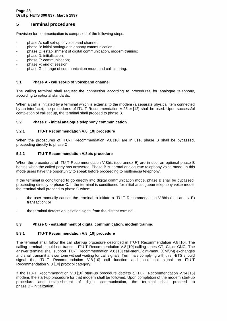
Page 28Draft prI-ETS 300 837: March 1997
5 Terminal procedures
Provision for communication is comprised of the following steps:
- phase A: call set-up of voiceband channel;- phase B: initial analogue telephony communication;- phase C: establishment of digital communication, modem training;- phase D: initialization;- phase E: communication;- phase F: end of session;- phase G: change of communication mode and call clearing.
5.1 Phase A - call set-up of voiceband channel
The calling terminal shall request the connection according to procedures for analogue telephony,according to national standards.
When a call is initiated by a terminal which is external to the modem (a separate physical item connectedby an interface), the procedures of ITU-T Recommendation V.25ter [12] shall be used. Upon successfulcompletion of call set up, the terminal shall proceed to phase B.
5.2 Phase B - initial analogue telephony communication
5.2.1 ITU-T Recommendation V.8 [10] procedure
When the procedures of ITU-T Recommendation V.8 [10] are in use, phase B shall be bypassed,proceeding directly to phase C.
5.2.2 ITU-T Recommendation V.8bis procedure
When the procedures of ITU-T Recommendation V.8bis (see annex E) are in use, an optional phase Bbegins when the called party has answered. Phase B is normal analogueue telephony voice mode. In thismode users have the opportunity to speak before proceeding to multimedia telephony.
If the terminal is conditioned to go directly into digital communication mode, phase B shall be bypassed,proceeding directly to phase C. If the terminal is conditioned for initial analogueue telephony voice mode,the terminal shall proceed to phase C when:
- the user manually causes the terminal to initiate a ITU-T Recommendation V.8bis (see annex E)transaction; or
- the terminal detects an initiation signal from the distant terminal.
5.3 Phase C - establishment of digital communication, modem training
5.3.1 ITU-T Recommendation V.8 [10] procedure
The terminal shall follow the call start-up procedure described in ITU-T Recommendation V.8 [10]. Thecalling terminal should not transmit ITU-T Recommendation V.8 [10] calling tones CT, CI, or CNG. Theanswer terminal shall support ITU-T Recommendation V.8 [10] call-menu/joint-menu (CM/JM) exchangesand shall transmit answer tone without waiting for call signals. Terminals complying with this I-ETS shouldsignal the ITU-T Recommendation V.8 [10] call function and shall not signal an ITU-TRecommendation V.8 [10] protocol category.
If the ITU-T Recommendation V.8 [10] start-up procedure detects a ITU-T Recommendation V.34 [15]modem, the start-up procedure for that modem shall be followed. Upon completion of the modem start-upprocedure and establishment of digital communication, the terminal shall proceed tophase D - initialization.

Page 29Draft prI-ETS 300 837: March 1997
If the ITU-T Recommendation V.8 [10] procedure fails to detect an ITU-T Recommendation V.34 [15]modem, or the handshake and the establishment of the digital connection is not successful, after asuitable period the calling terminal may, depending on predetermined configuration, go to telephonymode, disconnect the line, or go to another operating mode more suitable for the detected modem. Suchother modes are outside the scope of this I-ETS.
NOTE: The terminal shall wait for a suitable call set-up period, in addition to processing, signaldetection, and maximum round-trip delays, before deciding on further action.
5.3.2 ITU-T Recommendation V.8bis procedure
The terminal shall follow the call start-up procedure described in ITU-T Recommendation V.8bis (seeannex E). If the ITU-T Recommendation V.8bis (see annex E) procedure detects that the distant terminalis not capable of ITU-T Recommendation V.8bis (see annex E), but is capable of ITU-TRecommendation V.8 [10], the Phase C procedure for ITU-T Recommendation V.8 [10] shall be followed.If the ITU-T Recommendation V.8bis (see annex E) procedure detects a distant ITU-T RecommendationH.324 [26] terminal supporting the capabilities desired for this call, the ITU-T Recommendation V.34 [15]start-up procedure shall be followed. Upon completion of the ITU-T Recommendation V.8bis (see annexE) procedures and establishment of digital communication, the terminal shall proceed to phase D -initialization.
NOTE: Some successful ITU-T Recommendation V.8bis (see annex E) transactions result ina return to telephony mode (Phase B).
If the ITU-T Recommendation V.8bis (see annex E) procedure fails, results in a return to analogueuetelephony, or the handshake and the establishment of the digital connection is not successful after theperiod specified in ITU-T Recommendation V.8bis (see annex E), the calling terminal may, depending onpredetermined configuration, go to telephony mode, disconnect the line, or go to another operating modemore suitable for the detected modem. Such other modes are outside the scope of this I-ETS.
5.4 Phase D - initialization
After digital communication has been established, a minimum of 16 HDLC flags shall be transmitted inorder to ensure synchronization. Following this, system to system communication shall be initiated usingthe ITU-T Recommendation H.245 [2] control channel. Since no multiplex table entries have yet been sentto the receiver, initial control messages shall be sent using multiplex table entry 0.
Terminal system capabilities are exchanged by transmission of the TerminalCapabilitySet message. Thiscapability PDU shall be the first message sent. The MasterSlaveDetermination message shall also be sentat this time, in which the terminals exchange random numbers, according to the procedure in ITU-TRecommendation H.245 [2], to determine the master and slave terminals. Terminals complying with thisI-ETS shall be capable of operating in both master and slave modes, and shall set terminalType to 128and set statusDeterminationNumber to choose a random number in the range 0 to 224-1. Only one randomnumber shall be chosen by the terminal for each call, except in the case of identical random numbers, asdescribed in ITU-T Recommendation H.245 [2].
If the initial capability exchange or master/slave determination procedures fail, these should be retried atleast twice before the terminal abandons the connection attempt and proceeds to phase G.
NOTE: The range of terminalTypes from 0 to 127 is reserved for possible use by MCUs orother non-terminal devices which may need to be slave at all times and the range 129to 255 is reserved for possible use by MCUs or other non-terminal devices which mayneed to be master at all times.
After these procedures are complete, and the far-end's capabilities have been received, the procedures ofITU-T Recommendation H.245 [2] may then be used to open logical channels for various informationstreams. Multiplex table entries may be sent before or after logical channels are opened, but informationshall not be transmitted over a logical channel until the channel is open, and an appropriate ITU-TRecommendation H.223 [1] multiplex table entry has been defined.

Page 30Draft prI-ETS 300 837: March 1997
5.4.1 Exchange of video by mutual agreement
The indication videoIndicateReadyToActivate , "Video Indicate Ready-to-activate", is defined in ITU-TRecommendation H.245 [2]. Its use is optional, but when used the procedure shall be as follows:
- Terminal X has been set so that video is not transmitted until, the remote terminal has alsoindicated readiness to transmit video. Terminal X shall send the indicationvideoIndicateReadyToActivate when the initial capability exchange has been completed, but shallnot transmit a video signal until it has received either videoIndicateReadyToActivate or incomingvideo.
A terminal which has not been set in this optional way is not obliged to wait until receipt ofvideoIndicateReadyToActivate or video before initiating its video transmission.
5.5 Phase E - communication
During a session the procedures for changing logical channel attributes, capability, receive mode etc. shallbe carried out as defined in Recommendation ITU-T Recommendation H.245 [2].
5.5.1 Rate changes and retrains
During phase E communication, the modem may retrain or alter its rate of data transmission, with orwithout momentary disruption of data transmission and loss of data. Upon any such momentary disruptionof data transfer, the terminal shall not restart phase D, but shall remain in phase E and execute thenormal error recovery procedures according to ITU-T Recommendation H.223 [1].
5.5.2 Involuntary disconnection
Should the terminal detect involuntary, unrecoverable loss of modem communication, or of the underlyingPSTN connection, the terminal shall immediately proceed to phase G, analogue telephony mode or linedisconnection, bypassing phase F.
5.6 Phase F - end of session
Either terminal may initiate the end of the session. The initiating terminal shall use following procedure:
1) for each logical channel carrying video, it shall stop sending video at the end of a complete SDU andthen close the logical channel;
2) it shall close all logical channels carrying data and audio;
3) it shall transmit the message EndSessionCommand , and then discontinue all ITU-TRecommendation H.245 [2] message transmissions. This message shall contain an indication to thefar end regarding the mode the terminal will enter after the end of the session (disconnect line,analogue telephony, or other mode);
4) on subsequent receipt of EndSessionCommand from the remote end, it shall proceed to phase G,except that if the initiating terminal indicated an intention to disconnect the line after the end ofsession, the terminal shall not wait for receipt of EndSessionCommand from the remote end, but shallproceed directly to phase G.
A terminal receiving EndSessionCommand without first having transmitted it shall follow (1) to (3) above,then proceed to phase G.
5.7 Phase G - change of communication mode and call clearing
If the terminal arrived at phase G by involuntary disconnection, it shall disconnect or revert to analoguetelephony, depending on predetermined configuration.
A terminal wishing to terminate a call shall first initiate session end procedure described in phase F.
Page 31Draft prI-ETS 300 837: March 1997
In phase G, the terminal shall proceed as it indicated in the EndSessionCommand message. If it indicateda change to another digital communication mode, it shall begin the new mode at the equivalent ofphase D. Otherwise, it shall initiate the cleardown procedures defined in ITU-TRecommendation V.34 [15], except that it shall not physically disconnect the PSTN connection if itindicated an intention to revert to analogue telephony mode.
These procedures ensure that:
- the distant terminal does not erroneously invoke a fault procedure;
- the human user gets the right indications via tones and announcements from the networkexchange;
- relevant messages can be displayed for the human user by the terminal.
6 Interoperation with other terminals
6.1 Speech only terminals
Videophones complying with this I-ETS shall support interoperation with analogue speech-onlytelephones.
6.2 ETS 300 145 multimedia telephone terminals attached to the ISDN
Interoperation with multimedia telephone terminals over the Integrated Services Digital Network (ISDN)(ETS 300 145 [22]) can be provided by:
- using an interworking function; or
- using dual-mode (ISDN and PSTN) terminals on the ISDN.
An interworking function compliant with this I-ETS/ETS 300 145 [22] can be located at the interfacebetween ISDN and PSTN signals. It transcodes the ITU-T Recommendation H.223 [1] andETS 300 144 [21] multiplexers and the content of control, audio, and data logical channels between theETS 300 145 [22] protocols and those compliant with this I-ETS.
In order to ease communication between terminals complying with this I-ETS and ETS 300 145 [22]terminals via interworking functions, terminals compliant with this I-ETS which support video shall supportthe ITU-T Recommendation H.261 [5] video Codec in the QCIF picture format so that the additional delayof video transcoding can be avoided. When this mode is in use, interworking functions shall insert andremove ITU-T Recommendations H.261 [5] and H.263 [4] BCH error correction and error correctionframing as appropriate for each terminal type. Terminals complying with this I-ETS shall respond to theFlowControlCommand , so that transmitted video streams can be matched to the ETS 300 145 [22] videobit rate in use by the ETS 300 144 [21] multiplex.
Dual-mode (ETS 300 145 [22] and terminals compliant with this I-ETS) terminals on the ISDN shall sendPSTN signals compliant with this I-ETS by the use of a "modemfunction", which generates and receives aITU-T Recommendation V.34 [15] analogue signal encoded as an ITU-T Recommendation G.711 [20]audio bit-stream over the ISDN.
6.3 Multimedia telephone terminals over mobile radio
It is expected that multimedia telephone terminals will also be used on mobile radio networks. Ratematching between wireless terminals and PSTN terminals can be achieved by the use of theFlowControlCommand . Wireless operation is for further study.

Page 32Draft prI-ETS 300 837: March 1997
7 Optional enhancements
7.1 Data facilities
A terminal may have physical I/O ports for external telematic and other equipment, or there may be dataapplications within the terminal itself. Data transmission may be activated and deactivated by local action.When a logical channel is opened to carry data originating at a port, the portNumber parameter of theITU-T Recommendation H.245 [2] OpenLogicalChannel message should contain the number of therelevant port, so that data on the logical channel may be routed to a corresponding port at the far-end, ifso desired by the far-end user. For example, in the case where a terminal has general-purpose physicalI/O ports intended for connection to telematic or other equipment, such ports might be labelled "1", "2","3", etc., up to the number of actual ports.
7.2 Encryption
Encryption may optionally be used by terminals complying with this I-ETS. Encryption, including selectionof algorithm and key exchange, shall conform to the procedures of ITU-T Recommendations H.233 [6]and H.234 [7] with the following modifications to the procedures defined in ITU-TRecommendation H.233 [6]. The ability to support encryption shall be signalled by the presence of theh233EncryptionTransmitCapability and h233EncryptionReceiveCapability parameters of the Capabilitymessage.
In ITU-T Recommendation H.233 [6], specific reference is made to ETS 300 144 [21] in describing howencryption takes place. In applying ITU-T Recommendation H.233 [6] to terminals complying with thisI-ETS, references to ETS 300 144 [21], Frame Aligment Signal (FAS), and bit-rate allocation signal (BAS)channels therein shall be ignored and appropriate substitute recommendations be taken from thissubclause. Messages referred to as carried in the ITU-T Recommendation H.221 (see annex E)Encryption Control Signal (ECS) channel shall be re-interpreted as being carried within the encryptionSEparameter of the EncryptionCommand or Encryption Initialization Vector (EIV) logical channel, as specifiedbelow.
7.2.1 EncryptionSE messages
ITU-T Recommendation H.233 [6] Session Exchange (SE) messages shall be carried in the encryptionSEparameter of the EncryptionCommand message. Since the ITU-T Recommendation H.245 [2] controlchannel is carried on a reliable data link layer using retransmission of errored frames, the error protectionbits described in ITU-T Recommendation H.233 [6] shall not be applied to SE messages.
The ITU-T Recommendation H.233 [6] header for SE messages shall have the binary value 00000000,indicating an SE message in a single block, not followed by related blocks.
The ITU-T Recommendation H.233 [6] media identifier value shall be binary 00000000, which shallindicate encryption of all logical channels except for the EIV and ITU-T Recommendation H.245 [2] controlchannels. The use of other values is for further study.
NOTE: Non-standard encryption algorithms may be referenced in SE messages afterassociating a non-standard algorithm with a ITU-T Recommendation H.233 [6]Algorithm Identifier value using the encryptionAlgorithmID parameter of theEncryptionCommand message.
7.2.2 EIV channel
The EIV logical channel is used for the transmission of ITU-T Recommendation H.233 [6] InitializationVector (IV) messages.
To ensure accurate synchronization of the IV messages with the ITU-T Recommendation H.223 [1]multiplexer bit-stream, the EIV channel is an independent logical channel which shall be non-segmentable, and shall use adaptation layer AL2 of the ITU-T Recommendation H.223 [1] multiplexer.The entire IV message, exactly as defined in ITU-T Recommendation H.233 [6], including error protectionbits, shall be placed in a single AL-SDU. The sequence number option of AL2 shall not be used.

Page 33Draft prI-ETS 300 837: March 1997
Messages carried within the EIV channel shall retain the error protection mechanism of ITU-TRecommendation H.233 [6].
7.2.3 Encryption procedure
The encryptor shall produce a pseudo-random bit-stream (cipher stream) corresponding to all bits outputby the ITU-T Recommendation H.223 [1] multiplex prior to insertion of flags and application of the HDLCzero-bit insertion procedure.
When encryption is activated according to ITU-T Recommendation H.233 [6], the ITU-TRecommendation H.223 [1] bit-stream shall, prior to flag insertion and application of the HDLC zero-bitinsertion procedure, be exclusive-ORed with the pseudo-random bit-stream generated by the encryptor.However, the exclusive-OR procedure shall not be applied to the ITU-T Recommendation H.223 [1]header byte and all bytes belonging to the ITU-T Recommendation H.245 [2] control channel or EIVchannel, which shall all be passed transparently to the HDLC zero-bit insertion and flag insertion stage.
For each transmitted ITU-T Recommendation H.223 [1] header byte or byte belonging to the EIV orcontrol channels, eight bits shall be discarded from the pseudo-random bit-stream generated by theencryptor. Nothing is discarded from the pseudo-random bit-stream for transmitted flags or for bits addedby the HDLC zero-bit insertion process.
The receiver shall apply the reverse procedure.
7.2.4 Encryption initialization vectors
Once an encrypted session is in progress, the transmitter should periodically send new IV messages inorder to limit the duration of repeated pseudo-random bit-streams in the event of a collision with apreviously used state of the pseudo-random bit-stream generator. The frequency of these messages isleft to the discretion of the implementor.
As shown in figure 3, new IVs take effect at the start of the next ITU-T Recommendation H.223 [1]MUX PDU following the MUX-PDU containing an IV message. The old IV continues in effect through theentirety of the MUX-PDU containing the IV message, at the end of which any remaining pseudo-randombits generated using the old IV are discarded. In order for the receiver to have time to process the new IVbefore needing to use it, the transmitter shall wait a minimum time after sending the last byte of the IVmessage, as specified by the receiver's h233IVResponseTime capability, before starting transmission ofthe next MUX-PDU. If necessary, the transmitter shall send idle flags to meet the receiver’sh233IVResponseTime requirement.
NOTE: Definition, by the implementor, of an appropriate ITU-T Recommendation H.223 [1]multiplex table entry allows bytes from other logical channels to follow an IV messagewithin the same MUX-PDU so that no transmission bandwidth is squandered inmeeting the receiver's IV processing delay requirement.
F H ……… IV ……………………… F F F H ……………….. F
New IV takes effect here
MUX-PDUMUX-PDU
h233IVResponseTime
F = flag, H = header byte, … = logical channel byte
Figure 3: Encryption IV synchronization

Page 34Draft prI-ETS 300 837: March 1997
7.2.5 Error recovery
In the event of line errors that cause flag emulation, flag erasure, or erroneous HDLC zero-bit removal, itis possible that a newly received flag, signifying the end of the previous MUX-PDU, will not align with thebyte boundaries of the preceding data. In order to maximize the resilience of the encryption systemagainst synchronization loss under these circumstances, the decryptor should, for each new flag received,re-align its pseudo-random bit-stream generator to the nearest byte boundary. This allows recovery fromup to at least three zero-bit removal errors between valid flags, although it does not provide any protectionagainst flag emulation or erasure.
In the event that the receiver suspects that it has lost encryption synchronization it shall send anencryptionIVrequest command, except that it should not re-send such commands at intervals less than themaximum expected round-trip response time.
Upon receipt of an encryptionIVrequest command, the transmitter shall, at its earliest opportunity, send anew IV message, except that it should ignore encryptionIVrequest commands received within theminimum expected round-trip response time since sending the last IV message.
7.3 Multilink
Provision for multilink operation is for further study.
8 Multipoint considerations
Terminals compliant with this I-ETS may be used in multipoint configurations via interconnection throughMCUs, as indicated in figure 4 (cascaded MCU operation is for further study).
Term inal Term inal Term inal Term inal
M CU
M CU
M CUTerm inal
Figure 4: Multipoint configuration
8.1 Establishment of common mode
MCUs may force terminals into a particular common mode of transmission by sending to the terminal areceive capability set listing only the desired mode of transmission. Terminals compliant with this I-ETSshall obey the MultipointModeCommand message.
8.2 Multipoint rate matching
Since the modems on each link in a multipoint configuration may be operating at different bit rates, MCUsmay choose to send FlowControlCommand messages to limit the transmitted bit rates to those which canbe sent to receivers.

Page 35Draft prI-ETS 300 837: March 1997
8.3 Multipoint lip synchronization
In a multipoint configuration, each terminal compliant with this I-ETS may be transmitting a differentH223SkewIndication message for associated video and audio channels. To enable lip synchronization atreceiving terminals, MCUs shall transmit accurate H223SkewIndication messages. MCUs may accomplishthis by adding delay to equalize the audio/video skew for all transmitting terminals, or, when switchingbetween broadcasting terminals, may transmit a new H223SkewIndication message reflecting theaudio/video skew of the current broadcaster.
8.4 Multipoint encryption
In a multipoint configuration the MCU is considered to be a trusted entity. Each port of the MCUencrypts/decrypts the ITU-T Recommendation H.223 [1] bit-stream from the terminal or MCU attached tothat port as though it were an terminal in accordance with section 7.2 of ITU-TRecommendation H.223 [1].
8.5 Cascaded MCU operation
Multipoint operation in a cascaded MCU configuration is for further study.
9 Maintenance
9.1 Loopbacks for maintenance purposes
Some loopback functions are defined in ITU-T Recommendation H.245 [2] to allow verification of somefunctional aspects of the terminal, to ensure correct operation of the system and satisfactory quality of theservice to the remote party. The message loopback off (MaintenanceLoopOffCommand ) requires that allloopbacks currently in effect be turned off.
9.1.1 Normal mode
Normal (no loopback) operation mode is illustrated in (a) of figure 5.
9.1.2 System loopback
Operation in system loopback mode is for further study.
9.1.3 Media loopback
Media loopback operates at the analogue I/O interface (towards modem). Upon receiving the mediaLooprequest, loopback of the content of the selected logical channel shall be activated as close as possible tothe analogue interface of the video/audio Codec towards the video/audio Codec, so that decoded andrecoded media content is looped, as indicated in (c) figure 5. While in this mode, the terminal shallrespond normally to received data, including ITU-T Recommendation H.245 [2] messages. Medialoopback provides a subjective test of terminal operation through the far-end Codec for human userevaluation. It should be used only on video and audio channels.
This loopback is optional, and should be used only on logical channels opened using the bi-directionalchannel procedures of ITU-T Recommendation H.245 [2].
9.1.4 Logical channel loopback
Logical channel loopback operates in the ITU-T Recommendation H.223 [1] multiplexer (toward modem).Upon receiving the logicalChannelLoop request, each received ITU-T Recommendation H.223 [1]MUX-SDU for the specified logical channel shall be looped back to the transmitter on the correspondingreverse logical channel, as indicated in (d) figure 5. While in this mode, the terminal shall respondnormally to received data, including ITU-T Recommendation H.245 [2] messages.
This loopback is optional, and should be used only on logical channels opened using the bi-directionalchannel procedures of ITU-T Recommendation H.245 [2].

Page 36Draft prI-ETS 300 837: March 1997
Codec Multiplex Modem
b) System loopback
Codec Multiplex Modem
a) Normal
Codec Multiplex Modem
c) Media loopback
Codec Multiplex Modem
d) Logical Channel loopback
One logical channel only
Other logical channels
Figure 5: Loop back

Page 37Draft prI-ETS 300 837: March 1997
Annex A (normative): Protocol stack for control channel
This annex defines the data protocol stack for use with the control channel of terminals which comply withthis I-ETS.
A.1 General
Figure A.1 shows the control channel protocol stack for use with this I-ETS.
ITU-T Recommendation H.245 [2]
SRP or LAPM/ ITU-TRecommendation V.42 [13]
ITU-T RecommendationH.223 - framed AL1
ITU-T RecommendationH.223 - MUX (see annex E)
Physical Layer ( ITU-TRecommendation V.34 [15] modem)
Figure A.1: Protocol stack for control channel
The control protocol of ITU-T Recommendation H.245 [2] requires a reliable link layer for properoperation.
Two means of transporting MultimediaSystemControlPDU messages are defined: SRP frames andLAPM/ITU-T Recommendation V.42 [13] frames. In the SRP mode each SRP command frame must beacknowledged with an SRP response frame before the next command can be transmitted. In theLAPM/ITU-T Recommendation V.42 [13] mode, multiple frames may be sent in a streaming mode, beforean acknowledgment is received for the first frame. All terminals shall support the SRP mode, and shalluse SRP as the ITU-T Recommendation H.245 [2] link layer upon initial communication. TheLAPM/ITU-T Recommendation V.42 [13] mode is optional, and is preferred for use by complex terminals.
In both cases, bits produced by the ITU-T Recommendation X.691 (see annex E) encoding process shallbe put into the byte of an information field, with the first bit generated going into the most significant bit(MSB) of the first byte, and progressing down to the least significant bit (LSB) of the last byte. One ormore complete MultimediaSystemControlPDU messages may be sent in each information field, to betransported in a single SRP or LAPM frame.
Terminals complying with this I-ETS and capable of using LAPM/ITU-T Recommendation V.42 [13] as thecontrol channel link layer, shall so indicate by setting the transportWithI-frames parameter of theH223Capability structure true. Such terminals, upon receiving the corresponding indication from thefar-end terminal, shall henceforth, and without further notification of intent, proceed to establish anerror corrected connection according to the procedures given in section 6.8.1.2 and subsequently transmitcontrol channel messages only using LAPM/ITU-T Recommendation V.42 [13] for the duration of theconnection. The terminal shall, however transmit a SRP response message in reply to any SRP commandmessage received.
The transition to LAPM/ITU-T Recommendation V.42 [13] mode shall take place regardless of the state ofany ITU-T Recommendation H.245 [2] transactions in progress; any pending transactions shall proceedusing LAPM/ITU-T Recommendation V.42 [13] for transfer of additional messages.
NOTE: Since the ITU-T Recommendation H.245 [2] control channel is not considered a datachannel, ability to operate the control channel over LAPM/ITU-TRecommendation V.42 [13] is signalled only in the transportWithI-frames parameter ofH223Capability , and is not signalled as a data protocol.

Page 38Draft prI-ETS 300 837: March 1997
A.2 SRP mode
All terminals shall support the transfer of MultimediaSystemControlPDU messages using SRP mode. EachSRP frame shall be placed in a single framed AL1 AL-SDU.
NOTE: The procedures of the SRP mode are based on those of eXchange IDentification (XID)frame transfer in ITU-T Recommendation V.42 [13].
A.2.1 SRP command frames
SRP command frames, as shown in figure A.2, shall be used to send ITU-T Recommendation H.245 [2]control messages. All fields shall be formatted as specified in Recommendation H.223 [1] (note that theseformats are consistent with ITU-T Recommendation V.42 [13]).
Header(1 byte)
Sequencenumber(1 byte)
Information field(one or more ASN.1 messages)
FCS(2 bytes)
Figure A.2: Format of SRP command frames for MultimediaSystemControlPDU messages
The SRP command frame header byte shall have the value binary 11111001 (decimal 249). This may beconsidered equivalent to an HDLC address byte with the Data Link Connection Identifier (DLCI) value 62,Command Response bit (C/R) bit set to 0, and Address field Extension (EA) bit set to 1.
The sequence number shall be set arbitrarily by a terminal for the first SRP command frame sent andshall be incremented modulo 256 for each new SRP command frame sent. Retransmissions of the sameSRP frame, sent according to the procedures below, shall not increment the sequence number, but shalluse the same sequence number as the original transmission, so that receivers can distinguish betweenseparate valid messages and retransmissions of a single message (possibly sent in error if the originalSRP response frame was lost).
The information field shall contain a whole number of bytes, not to exceed 2 048 bytes, representing oneor more MultimediaSystemControlPDU messages. The procedure specified by ITU-TRecommendation X.691 (see annex E) shall be used to fill any spare bits in the last byte.
The Frame Check Sequence (FCS) field shall contain a 16-bit CRC, applied to the entire frame content,as described in ITU-T Recommendation V.42 [13] section 8.1.1.6.1.
A.2.2 SRP response frames
SRP response frames shall be used to acknowledge correct receipt of SRP command frames from thefar-end. Each SRP response frame shall consist of a header byte and FCS field only, and shall not containany other fields.
The SRP response frame header byte shall have the value binary 11111011 (decimal 251). This may beconsidered equivalent to an HDLC address byte with the DLCI value 62, C/R bit set to 1, and EA bit setto 1.
The FCS field shall contain a 16-bit CRC, applied to the entire frame content, as described in ITU-TRecommendation V.42 [13] section 8.1.1.6.1.
A.2.3 SRP procedure at transmitter
The SRP procedure makes use of an acknowledgement timer T401 and retransmission counter N400.
The period of T401 is a local matter; the two terminals may operate with different periods of T401.Appendix IV of ITU-T Recommendation V.42 [13] shows the various factors that influence T401.
The maximum value of N400 is a local matter; the two terminals may operate with different maximumvalues of N400. While no default maximum is specified for N400, it should be at least 5.

Page 39Draft prI-ETS 300 837: March 1997
When the terminal transmits a new SRP command frame, timer T401 shall then be started and theretransmission counter, N400, reset. No additional SRP command frames shall be sent until a responseSRP frame with correct header and FCS is received, or timer T401 expires.
If a valid SRP response frame is received, a new SRP command frame, with an incremented sequencenumber, may be transmitted.
If timer T401 expires before receipt of a valid SRP response frame, the terminal shall:
- retransmit the SRP command (with the same sequence number) as above;- restart timer T401; and- increment the retransmission counter (N400).
After retransmission of the SRP command N400 times and failure to receive a valid SRP response, theterminal shall consider modem communication to be lost, and take appropriate action.
A.2.4 SRP procedure at receiver
On receipt of an SRP command frame with correct header and FCS the receiving terminal shallacknowledge by transmitting an SRP response frame within 500 ms.
If the received SRP command frame has the same sequence number as the previously receivedcommand frame, it shall not be passed to the ITU-T Recommendation H.245 [2] layer, since it is aretransmission of an already-processed command.
Receipt of all other frames shall be ignored, except that if the terminal has signalled ability to operate inLAPM/ITU-T Recommendation V.42 [13] mode, the receiver shall check the DLCI value of received frameheader. If the DLCI value matches that specified for use in the LAPM/ITU-T Recommendation V.42 [13]mode, the terminal shall respond according to the procedures of LAPM/ITU-T Recommendation V.42 [13],as described below.
A.3 LAPM/ITU-T Recommendation V.42 mode
Terminals may optionally support the transfer of MultimediaSystemControlPDU messages usingLAPM/ITU-T Recommendation V.42 [13].
SRP frames shall be used to transfer MultimediaSystemControlPDU messages before LAPM/ITU-TRecommendation V.42 [13] transmission is initiated but shall not be used for this purpose afterLAPM/ITU-T Recommendation V.42 [13] transmission has been used.
In the LAPM/ITU-T Recommendation V.42 [13] mode, the information field, as defined for the SRP modeabove, shall be placed into a single LAPM/ITU-T Recommendation V.42 [13] I-frame and transferredusing procedures of LAPM/ITU-T Recommendation V.42 [13], as in section 6.8.1.2, except that theprocedures for opening logical channels shall not be used, as the control channel is considered alreadyopen at the start of digital communication.
The address field shall be one byte with the 6-bit DLCI field set to binary 111111 (decimal 63).
ITU-T Recommendation V.42bis [14] data compression should not be used.
Default values for all ITU-T Recommendation V.42 [13] parameters shall be as specified in therecommendation, except for N401, maximum number of bytes in an information field, which shall have adefault value of 2 048 bytes, in order to accommodate large capability sets.

Page 40Draft prI-ETS 300 837: March 1997
Annex B (normative): HDLC Frame structure transparency for asynchronoustransmission
When operating in the HDLC frame tunneling mode, the terminal shall implement the following procedurestaken from ISO/IEC 3309 [19] section 4.5.2 at the asynchronous ITU-T Recommendation V.24 (seeannex E) interface:
- the control escape byte is a transparency identifier that identifies a byte occurring within a frame towhich the following transparency procedure is applied. The encoding of the escape byte is given infigure B.1;
0 1 1 1 1 1 0 1
8 7 6 5 4 3 2 1
Complemented bit
First bit transmitted
Figure B.1: Control escape byte for HDLC frame tunneling procedure
- the transmitter shall examine the frame content between the opening and closing flag sequences(01111110) including the address, control, and FCS fields and, following completion of the FCScalculation, shall:
a) upon the occurrence of the flag or a control escape byte, complement the 6th bit of the byte;and
b) insert a control escape byte immediately preceding the byte resulting from the above prior totransmission;
- the receiver shall examine the frame content between the two flag bytes and shall, upon receipt of acontrol escape byte and prior to FCS calculation:
a) discard the control escape byte; and
b) restore the immediately following byte by complementing its 6th bit.
Other byte values may optionally be included in the transparency procedure by the transmitter.

Page 41Draft prI-ETS 300 837: March 1997
Annex C (informative): Bit and octet order
This appendix is supplied as a summary of bit and byte order in this I-ETS, including ITU-TRecommendations H.223 [1], H.261 [5], H.263 [4], H.245 [2], and G.723.1 [3] . In case of any discrepancythe normative text of the various recommendations shall take precedence over this appendix.
ITU-T Recommendations H.261 [5], H.263 [4], G.723.1 [3], and H.245 [2] each produce a sequence of bitswhich are delivered as bytes to the ITU-T Recommendation H.223 [1] multiplexer. Within this sequence ofbits there are fields of various lengths, in some cases aligned with byte boundaries. In the case of ITU-TRecommendations H.261 [5], H.263 [4], G.723.1 [3], and H.245 [2] these fields are orderedmost-significant-bit (MSB) first. Figure B.1 illustrates this, with "M" indicating the MSB of each field and "L"indicating the least-significant-bit (LSB) of each field.
M L M L M L M L M L lastfirst
Figure B.1: Output from ITU-T Recommendations H.261/H.263/G.723/H.245
Upon delivery to the ITU-T Recommendation H.223 [1] multiplexer, this bit sequence is split into bytes,each with a defined MSB/LSB position, as shown in figure B.2.
M L M L M L M L M L lastfirst
octet n octet n+1 octet n+2 octet n+3 octet n+4 octet n+5
M L M L M L M L M L M L
Figure B.2: Output split into bytes
The ITU-T Recommendation H.223 [1] multiplexer then transmits each of these bytes in the order LSBfirst (the reverse of the original order), applying the transparency procedure (inserting a "0" after eachsequence of five "1" s) as it does so.
For example, a sequence of six bytes, with hexadecimal values 0x92, 0xF1, 0x39, 0x35, 0x31, 0x30 wouldbe transmitted as shown in figure B.3.
lastfirst
octet n octet n+1 octet n+2 octet n+3 octet n+4 octet n+5
M L M L M L M L M L M L
10010010 11110001 00111001 00110101 00110001 00110000
0x92 0xF1 0x39 0x35 0x31 0x30
is transmitted as:
01001001first last10001111 10011100 10101100 10001100 00001100
0 bit will be inserted here
Figure B.3: Example sequence

Page 42Draft prI-ETS 300 837: March 1997
Annex D (informative): ITU-T Recommendation V.8bis codepoints
ITU-T Recommendation V.8bis (see annex E) capability exchange may be used during call set-up to helpterminals quickly decide, in the most common cases, if operation in a mode compliant with this I-ETS isdesired. ITU-T Recommendation V.8bis (see annex E) capabilities indicate only the most basic andcommonly used modes, and are not a substitute for ITU-T Recommendation H.245 [2] procedures. If anoperational mode not signalled by ITU-T Recommendation V.8bis (see annex E) is desired, the terminalmust complete call establishment and perform an ITU-T Recommendation H.245 [2] capabilitiesexchange to determine if the far-end terminal supports the desired mode.
Within the ITU-T Recommendation V.8bis (see annex E) Communications Capabilities (CC) field forterminals complying with this I-ETS, the CC field is formatted into one or more sub-fields. Each sub-fieldends with the byte in which bit [n] is set to 1. Following the first sub-field, the remaining sub-fields, ifpresent, shall appear in the same order in which the bits indicating their presence are transmitted.
NOTE: Implementors should refer directly to ITU-T Recommendation V.8bis (see annex E) forthe actual bit assignments.
In the first sub-field the following bits are allocated:
Name MeaningVideo Shall be set only if bi-directional video is supported as per this
I-ETS (subclause 4.6).Audio Shall be set only if bi-directional audio is supported as per this
I-ETS (subclause 4.7).Encryption Shall be set only if encryption is supported as per this I-ETS
(subclause 7.2).Data Indicates that a data subfield is present. Shall be set only if one
or more bits in the data subfield are set.
NOTE: Possible future allocations include Profiles.
In the Data subfield, the following bits are allocated:
Name MeaningITU-T Recommendation T.120 [17] Shall be set only if ITU-T Recommendation T.120 [17]
conferencing is supported as per subclause 4.8.2.1.ITU-T Recommendation T.84 [16] Shall be set only if ITU-T Recommendation T.84 [16] still image
transfer is supported as per subclause 4.8.2.2)ITU-T Recommendation T.434 [18] Shall be set only if ITU-T Recommendation T.434 [18] file
transfer is supported as per subclause sec. 4.8.2.3.ITU-T Recommendation V.42 [13] Shall be set only if ITU-T Recommendation V.42 [13] user data
is supported as per subclauses 4.8.1.2/4.8.2.6).ITU-T Recommendation V.14 [11] Shall be set only if ITU-T Recommendation V.14 [11] user data
is supported as per subclauses 4.8.1.1/4.8.2.6).PPP Shall be set only if IETF Point-to-Point protocol is supported via
the Network Layer NLPID as per subclause 4.8.2.5.
NOTE: Other modes beside those indicated in ITU-T Recommendation V8bis (see annex E),such as unidirectional modes, may be supported by terminals as signalled via ITU-TRecommendation H.245 [2] capabilities exchange.

Page 43Draft prI-ETS 300 837: March 1997
Annex E (informative): Bibliography
- ITU-T Recommendation G.728 (1992): "Coding of speech at 16 kbit/s using low-delay code excitedlinear prediction".
- ITU-T Recommendation H.221 (1995): "Frame structure for a 64 to 1920 kbit/s channel inaudiovisual teleservices".
- ITU-T Recommendation H.230 (1993): "Frame-synchronous control and indication signals foraudiovisual systems".
- ITU-T Recommendation H.262 (1995): "Generic coding of moving Pictures and Associated Audio:Video - ISO/IEC 13818-2".
- ITU-T Recommendation T.30 (1993): "Procedures for document facsimile transmission in thegeneral switched telephone network".
- ITU-T Recommendation T.35 (1991): "Procedure for the allocation of CCITT defined codes for non-standard facilities".
- ITU-IT Recommendation T.51 (1993): "Latin based coded character sets for telematic services".
- ITU-T Recommendation T.126 (1995): "Multipoint still image and annotation protocol".
- ITU-T Recommendation T.127 (1995): "Multipoint binary file transfer protocol".
- ITU-T Recommendation X.680 (1994): "Information Technology: Abstract Syntax Notation One(ASN.1): Specification of basic notation".
- ITU-T Recommendation X.691 (1995): "Information technology: ASN.1 encoding rules:Specification of Packed Encoding Rules (PER) Common text with ISO/IEC".
- IETF RFC 1490: "Multiprotocol Interconnect over Frame Relay, A. Malis et al, July 1993".
- IETF RFC 1661: "The Point to Point Protocol, W. Simpson, July 1994".
- ITU-T Recommendation V.8bis (1996): "Procedures for the identification and selection of commonmodes of operation between data circuit terminating equipment (DCE) and between data terminalequipment (DTE) over the general switched telephone network and on leased point-to-pointtelephone-type circuits".

Page 44Draft prI-ETS 300 837: March 1997
History
Document history
March 1997 Public Enquiry PE 9729: 1997-03-21 to 1997-07-18