INTERGRATED CIRCUITS LECTURE 17. History of Electronic Devices 1st Generation Electron tubes...
55
INTERGRATED CIRCUITS LECTURE 17
-
Upload
amos-gilmore -
Category
Documents
-
view
227 -
download
1
Transcript of INTERGRATED CIRCUITS LECTURE 17. History of Electronic Devices 1st Generation Electron tubes...

INTERGRATED CIRCUITS
LECTURE 17

History of Electronic Devices 1st Generation Electron tubes
INTERGRATED CIRCUITS LECTURE 17

2nd GenerationSemiconductor Devices, Diode and single Transistor

3rd GenerationSmall Scale Integrated Circuits (SSI): Less than 100
Transistors per Integrated Circuit or chipMedium Scale Integrated Circuits (MSI): 100 to 1000
Transistors per Integrated Circuit or chip
3rd GenerationSmall Scale Integrated Circuits (SSI): Less than 100 Transistors per Integrated Circuit or chipMedium Scale Integrated Circuits (MSI): 100 to 1000 Transistors per Integrated Circuit or chip

4th GenerationLarge Scale Integrated Circuits (LSI): 1000 to 10000 Transistors per Integrated Circuit or chip Very Large Scale Integrated Circuits (VLSI): 10000 to 1 million Transistors per Integrated Circuit or chip.
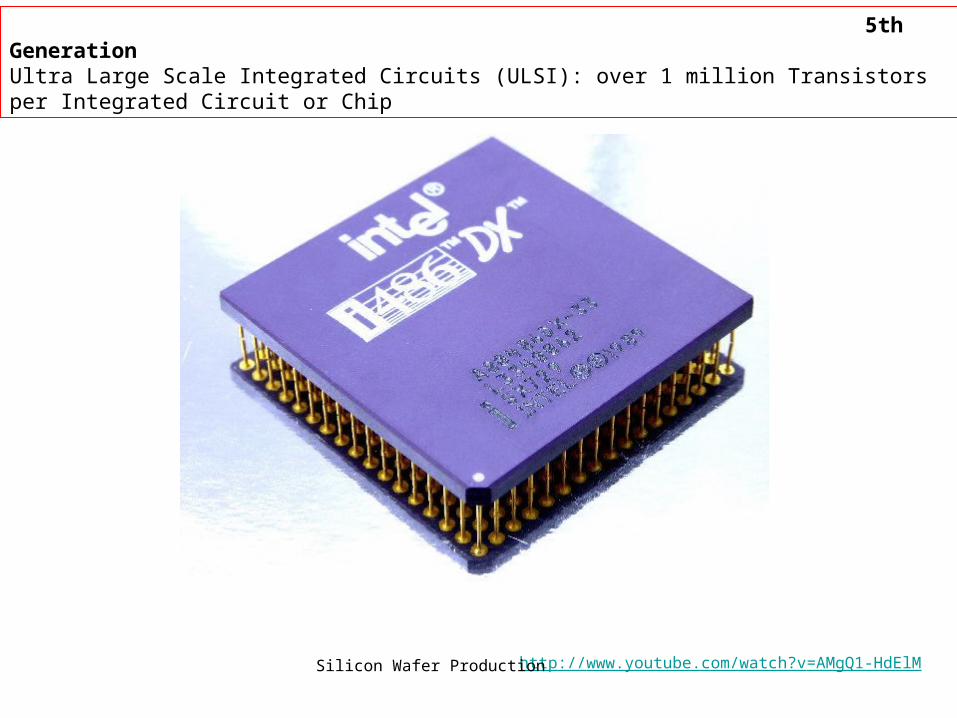
5th GenerationUltra Large Scale Integrated Circuits (ULSI): over 1 million Transistors per Integrated Circuit or Chip
http://www.youtube.com/watch?v=AMgQ1-HdElMSilicon Wafer Production

6th GenerationName of this technology yet to be determined: Over one billion transistors per Integrated Circuit or Chip
10-Core Xeon Westmere-EX 2,600,000,000 2011 Intel 32 nm 512 mm²

Radio shack notes p80-91


You tube: the intergrated circuit http://www.youtube.com/watch?v=uSRIc-sEgPw

555 audio oscillator
Voltage comparator
http://www.youtube.com/watch?v=qsP06waTvQYCollin's Lab: Exploratory IC torching

7404 IC six independent positive logic NOT GATES (INVERTERS)


DIFFERENT PACKAGE STYLES FOR IC’s

TYPES OF IC SOCKETS


http://www.williamson-labs.com/GREAT WEB SITE FOR ELECTRONICS

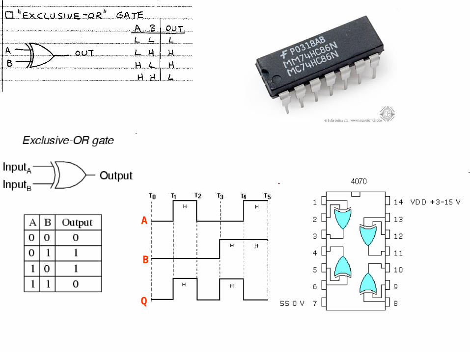
Q

A
B
Q

http://www.williamson-labs.com/480_logic.htmDigital logic animation

ELECTRONIC TOOLBOX: APP FOR IPHONE
http://www.youtube.com/watch?v=377dquuny4w
http://www.youtube.com/watch?v=rz_EfwJGIes.[iPad] iCircuit .


The BCD method codes each decimal digit in binary and stores it in its own byte. The binary method converts the entire decimal number into a binary number.

Transistor NOR Gate
A
B
Q
A
B
Q

A
B
Q


A tristate buffer can be thought of as a switch. If B is on, the switch is closed. If B is off, the switch is open.


Truth Table for Logic Gate Combination
Inputs Outputs
A B C D E Q
0 0 0 1 0 1
0 0 1 1 0 1
0 1 0 0 0 0
0 1 1 0 1 1
1 0 0 0 0 0
1 0 1 0 0 0
1 1 0 0 0 0
1 1 1 0 1 1
EXAMPLE LOGIC CIRCUITS http://www.technologystudent.com/elec1/dig5.htm
http://www.technologystudent.com/elec1/digq2.htmDIGITAL LOGIC EXAMINATION QUESTION - 2
EXAMPLE OF COMBINATIONAL LOGIC CIRCUIT

BCD-to-Seven-Segment Decoders/Drivers


AddressingInputSelectedb a
0 0 A
0 1 B
1 0 C
1 1 D
4-to-1 Channel Multiplexer 4 Channel Multiplexer using Logic Gates
Multiplexer Symbol

The Demultiplexer
1-to-4 Channel De-multiplexer
4 Channel Demultiplexer using Logic Gates
Demultiplexer SymbolAddressing
InputSelectedb a
0 0 A
0 1 B
1 0 C
1 1 D

The Digital EncoderUnlike a multiplexer that selects one individual data input line and then sends that data to a single output line or switch, a Digital Encoder more commonly called a Binary Encoder takes ALL its data inputs one at a time and then converts them into a single encoded output.
4-to-2 Bit Binary Encoder

Positional Encoders
Compass DirectionBinary Output
Q0 Q1 Q2
North 0 0 0
North-East 0 0 1
East 0 1 0
South-East 0 1 1
South 1 0 0
South-West 1 0 1
West 1 1 0
North-West 1 1 1

A 2-to-4 Binary Decoders.
Binary DecoderA Decoder is the exact opposite to that of an "Encoder". It is basically, a combinational type logic circuit that converts the binary code data at its input into one of a number of different output lines, one at a time producing an equivalent decimal code at its output.


The Basic SR Flip-flop Truth Table for this Set-Reset Function
State S R Q Q Description
Set
1 0 1 0 Set Q » 1
1 1 1 0 no change
Reset
0 1 0 1 Reset Q » 0
1 1 0 1 no change
Invalid
0 0 0 1memory with Q
= 0
0 0 1 0memory with Q
= 1
http://www.williamson-labs.com/
GOOD WEB SITE FOR ELECTRONICS
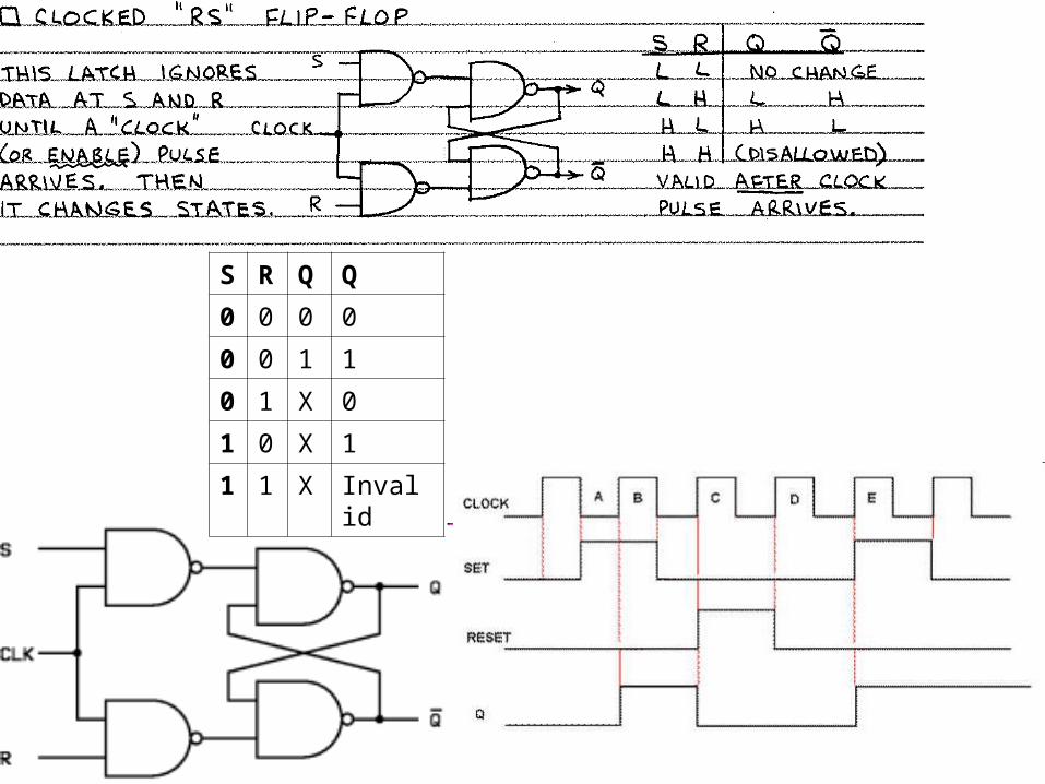
S R Q Q
0 0 0 0
0 0 1 1
0 1 X 0
1 0 X 1
1 1 X Invalid


4-bit Parallel-in to Parallel-out Shift Register
Basic Movement of Data through a Shift Register
Clock Pulse No QA QB QC QD
0 0 0 0 0
1 1 0 0 0
2 0 1 0 0
3 0 0 1 0
4 0 0 0 1
5 0 0 0 0

Frequency Division using Toggle Flip-flops
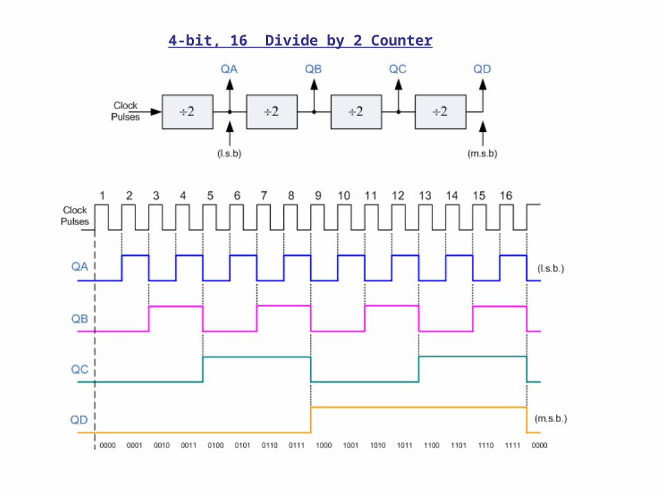
4-bit, 16 Divide by 2 Counter

http://www.technologystudent.com/elec1/count1.htm
THE 4017B DECADE COUNTER


74LS00 Pin Assignment :
7400 Logic Diagram