INTERFERENCE PHENOMENON IN DESIGN OF TRIMARAN … · 10th International Conference on Fast Sea...
18
10 th International Conference on Fast Sea Transportation FAST 2009, Athens, Greece, October 2009 INTERFERENCE PHENOMENON IN DESIGN OF TRIMARAN SHIP Igor Mizine 1 , Gabor Karafiath 2 , Patrick Queutey 3 and Michel Visonneau 3 1 CSC Advance Marine Center, Washington, DC USA 2 David Taylor Model Basin, Carderock Division, NSWC, Bethesda MD USA 3 Fluid Mechanics Laboratory - UMR6598, Centrale Nantes France ABSTRACT The hydrodynamic flow interference effect between the main and side hulls of Trimaran ships have a major influence on the total power and on the positioning of the side hulls. The main objective herein is to understand the physical reasons that explain the interference phenomenon. The hydrodynamic research and model testing of the large Trimaran ship - Heavy Air Lift Support Ship (HALSS) showed a large change in resistance ( 70%) due to a moderate (15% from length of center hull) shift in the longitudinal side hull position. Another observation is to the influence of the skegs on the stern flow. In order to fully understand the factors leading to the interference effects, several Computational Fluid Dynamics calculations were performed with various computational codes and compared to model test data. The paper contains the results of HALSS model testing at NSWCCD. Tests were performed on the center hull to select different bow sections and on Trimaran with three longitudinal and three transverse positions of the Small Waterplane Area HALSS side hulls. These experimental results are compared to CFD calculations by the following CFD codes: FINE TM /Marine, FLUENT, SWIFT (Ship Wave Inviscid Flow Theory) and MQLT (Modified Quasi Linear Theory). For all these test cases, comprehensive comparisons between computations and experimental data are presented to support the physical analysis in order to assist future design methodologies for multihull ships. 1. INTRODUCTION Existing and forthcoming markets demand large high-speed ships with wide decks for high-speed sea transportation of a large amount of high-value and relatively light cargo. A Trimaran configured from slender hulls is among the best design concepts for this mission. There are various Trimaran concepts, already built and in design studies. This paper is focused on Trimaran ships with relatively large side hulls, allowing the split of machinery propulsion between the hulls [Mizine, Amromin 1999]. Large side hulls add substantial wetted surface and friction drag. Thus it is important to minimize wave making drag in order to offset the additional friction drag. In the present paper we will mostly concentrate on resistance interference as a major factor influencing the hydrodynamic design of the Heavy Air Lift Support Ship (HALSS) concept. The HALSS Trimaran is an innovative Sealift Ship concept offering a large flight deck area suitable for multiple missions, including combat logistics support, vertical replenishment, search and rescue, special operations, cargo and troop transport. To ensure necessary speed of wind over the deck for C-130 aircraft landing and take off operations the HALSS Trimaran concept is designed to have a top speed of 35 knots. The analysis of the model resistance test results indicated very strong interference phenomenon, depending on the selection of Trimaran configuration parameters. In order to understand this phenomenon and formulate design recommendations for trimaran hydrodynamic and hull forms development a comprehensive set of calculations were performed, which included results of following applications: FINE TM /Marine, a CFD product of NUMECA International. This code is dedicated to marine applications and comprises a full-hexahedral unstructured mesh generator HEXPRESS TM , a free-surface RANS solver ISIS-CFD entirely developed by Ecole Centrale de Nantes and CNRS and a dedicated flow visualizer CFView, also developed by NUMECA. The free surface potential flow code SWIFT uses a higher order panel method, which employs a parabolic quadrilateral as a basic element.
Transcript of INTERFERENCE PHENOMENON IN DESIGN OF TRIMARAN … · 10th International Conference on Fast Sea...
10th International Conference on Fast Sea Transportation FAST 2009, Athens, Greece, October 2009
INTERFERENCE PHENOMENON IN DESIGN OF TRIMARAN SHIP
Igor Mizine1, Gabor Karafiath2, Patrick Queutey3 and Michel Visonneau3
1 CSC Advance Marine Center, Washington, DC USA
2 David Taylor Model Basin, Carderock Division, NSWC, Bethesda MD USA 3 Fluid Mechanics Laboratory - UMR6598, Centrale Nantes France
ABSTRACT The hydrodynamic flow interference effect between the main and side hulls of Trimaran ships have a major influence on the total power and on the positioning of the side hulls. The main objective herein is to understand the physical reasons that explain the interference phenomenon. The hydrodynamic research and model testing of the large Trimaran ship - Heavy Air Lift Support Ship (HALSS) showed a large change in resistance ( 70%) due to a moderate (15% from length of center hull) shift in the longitudinal side hull position. Another observation is to the influence of the skegs on the stern flow. In order to fully understand the factors leading to the interference effects, several Computational Fluid Dynamics calculations were performed with various computational codes and compared to model test data. The paper contains the results of HALSS model testing at NSWCCD. Tests were performed on the center hull to select different bow sections and on Trimaran with three longitudinal and three transverse positions of the Small Waterplane Area HALSS side hulls. These experimental results are compared to CFD calculations by the following CFD codes: FINETM/Marine, FLUENT, SWIFT (Ship Wave Inviscid Flow Theory) and MQLT (Modified Quasi Linear Theory). For all these test cases, comprehensive comparisons between computations and experimental data are presented to support the physical analysis in order to assist future design methodologies for multihull ships. 1. INTRODUCTION
Existing and forthcoming markets demand large high-speed ships with wide decks for high-speed sea transportation of a large amount of high-value and relatively light cargo. A Trimaran configured from slender hulls is among the best design concepts for this mission. There are various Trimaran concepts, already built and in design studies. This paper is focused on Trimaran ships with relatively large side hulls, allowing the split of machinery propulsion between the hulls [Mizine, Amromin 1999]. Large side hulls add substantial wetted surface and friction drag. Thus it is important to minimize wave making drag in order to offset the additional friction drag.
In the present paper we will mostly concentrate on resistance interference as a major factor influencing the hydrodynamic design of the Heavy Air Lift Support Ship (HALSS) concept. The HALSS Trimaran is an innovative Sealift Ship concept offering a large flight deck area suitable for multiple missions, including combat logistics support, vertical replenishment, search and rescue, special operations, cargo and troop transport. To ensure necessary speed of wind over the deck for C-130 aircraft landing and take off operations the HALSS Trimaran concept is designed to have a top speed of 35 knots.
The analysis of the model resistance test results indicated very strong interference phenomenon, depending on the selection of Trimaran configuration parameters. In order to understand this phenomenon and formulate design recommendations for trimaran hydrodynamic and hull forms development a comprehensive set of calculations were performed, which included results of following applications:
FINETM/Marine, a CFD product of NUMECA International. This code is dedicated to marine applications and comprises a full-hexahedral unstructured mesh generator HEXPRESSTM , a free-surface RANS solver ISIS-CFD entirely developed by Ecole Centrale de Nantes and CNRS and a dedicated flow visualizer CFView, also developed by NUMECA.
The free surface potential flow code SWIFT uses a higher order panel method, which employs a parabolic quadrilateral as a basic element.
10th International Conference on Fast Sea Transportation FAST 2009, Athens, Greece, October 2009
MQLT determines wave resistance by integrating the wave energy across the ship wake, but the density of wave energy is artificially limited by semi empirical constant value. This limitation makes it possible to combine fast computations similar to linear theory with the implicit account of nonlinearity of wave interference. 2. HALSS CONCEPT
The HALSS design is the latest evolution of a strategic long-term program to develop high speed Trimaran technology. This technology development has been an important part of research sponsored by the Center for Commercial Deployment of Transportation Technologies (CCDOTT), a Research and Development program administered through the Office of Naval Research. The concept of the HALSS is to provide support for military elements in Seabasing, strategic mobility and focused logistics during the undertaking of expeditionary warfare missions. The HALSS concept design is a 35-knot ship capable of delivering early entry of combat units up to 200 miles inland from a floating base 100 miles offshore. This is accomplished by loading, fuelling, launching, and recovering C-130J aircraft, while carrying enough cargo, troops, and fuel to allow the aircraft to move 8,000 tons of troops and materiel to the Joint Operating Theater, 300 nautical miles away, during 10 days of flight operations.
The relatively stable nature of the Trimaran design with low roll and pitch motions in a seaway is expected to offer the seakeeping and stability characteristics that are especially well suited for flight deck operations. The HALSS Trimaran concept is designed to have a top transit speed of 35 knots, which is necessary to ensure safe C-130J take-off and landing operations.
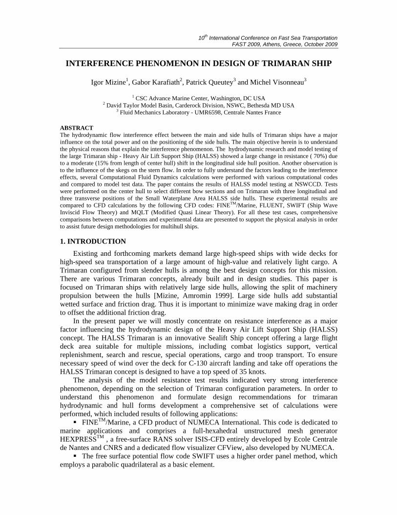
The general view of the HALSS is shown in Figure 1.
Figure 1: General view of HALSS concept
HALSS baseline machinery includes: two 2-stroke diesel engines, Wärtsilä 14RTA-96 or
equal, 80MW @ 102RPM, driving the two center hull propellers which would each be about 9m diameter. For side hull propulsion there are four 4-stroke Diesel Generator sets, Wärtsilä 18V46 or equal, 20.8MW @ 514RPM. Each pair of DG sets drives a 38MW electric motor in each of the side hulls, driving a fixed-pitch propeller or CPP at 180 RPM. The DG sets are located in the center hull; the motors are in each side hull. In the course of engineering studies the mission capabilities have been expanded, the required hull form characteristics have been refined, and the suitability of damaged and intact stability and speed/power requirements has been confirmed. The main dimensions of HALSS are the following:
FLIGHT DECK LENGTH 1,100 FT
FLIGHT DECK WIDTH / DOCKING HULL BEAM 274 FT / 180 FT
DRAFT 37.9 FT
DEPTH 100 FT
FULL DISPLACEMENT 65,000 MT
10th International Conference on Fast Sea Transportation FAST 2009, Athens, Greece, October 2009
3. HALSS EXPERIMENTAL CAMPAIGN
Bare hull resistance experiments were conducted for the HALSS Trimaran, a Heavy Air Lift Support Ship, as represented by Model 5651. During the first phase of testing, using just the HALSS center hull, two different bow sections, stem and bulbous bow, were tested. Further Phase 1 testing was completed with the HALSS center hull only, fitted with the best performing bow section and twin skegs, at two different drafts. The purpose of the second phase of testing was to investigate the resistance characteristics of the HALSS Trimaran characteristics of three different center-hull-to-side-hull draft variations. These experiments were completed with HALSS center hull drafts of 11 meters and 12 meters and various shallower side hull drafts with a matrix of three longitudinal and three transverse side hull configurations.
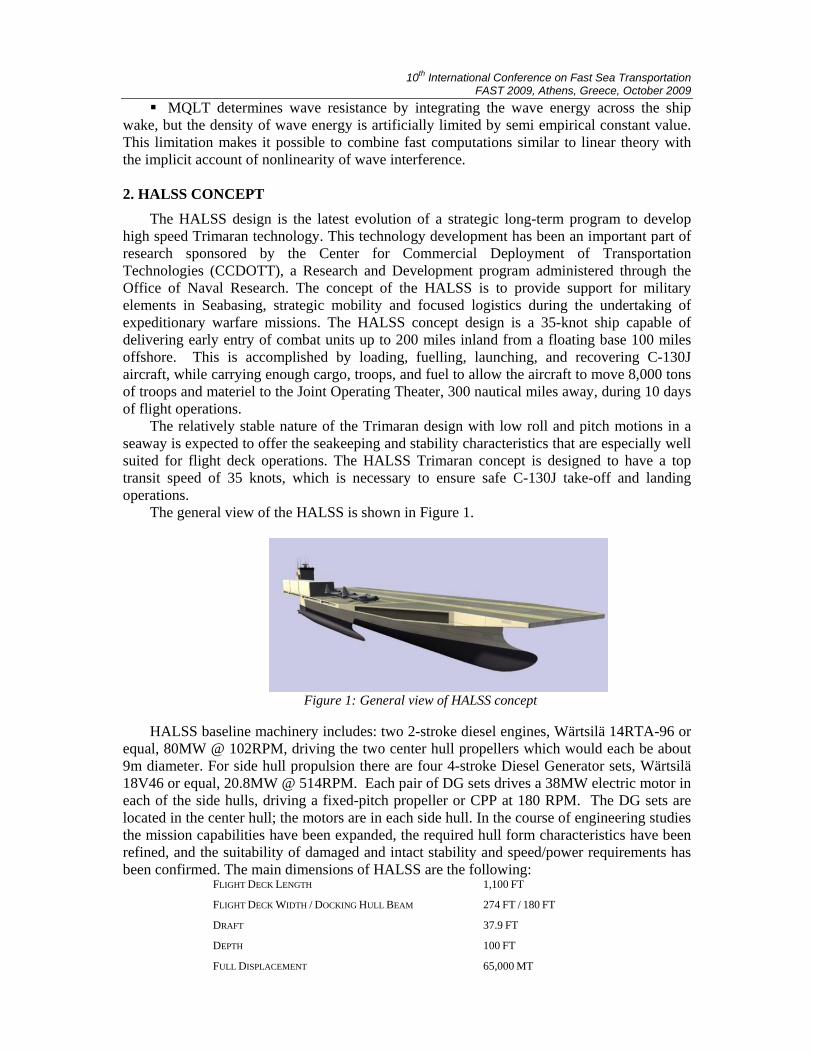
Model 5651 representing the HALSS Trimaran concept ship was made to a scale ratio (λ) of 54.0. Model 5651 consisted of three separate hulls, one center hull and two identical side hulls, connected together with aluminium cross structure pieces into a Trimaran. The center hull was constructed to allow for the testing of two different bow sections. The removable bow sections were the stem bow and the bulbous bow. Also, the center hull was fitted with twin removable skegs so that the bare hull resistance of the center hull could be experimentally determined. The two smaller side hulls were attached to the center hull, to form the Trimaran configurations, using two rigid aluminium extrusions as cross members attached with manufactured plates and brackets. Dry dock photographs of Model 5651, representing HALSS, are shown in Figure 2 and 3.
Figure 2: HALSS Model 5651 – Bow view Figure 3: HALSS Model 5651 – Stern view
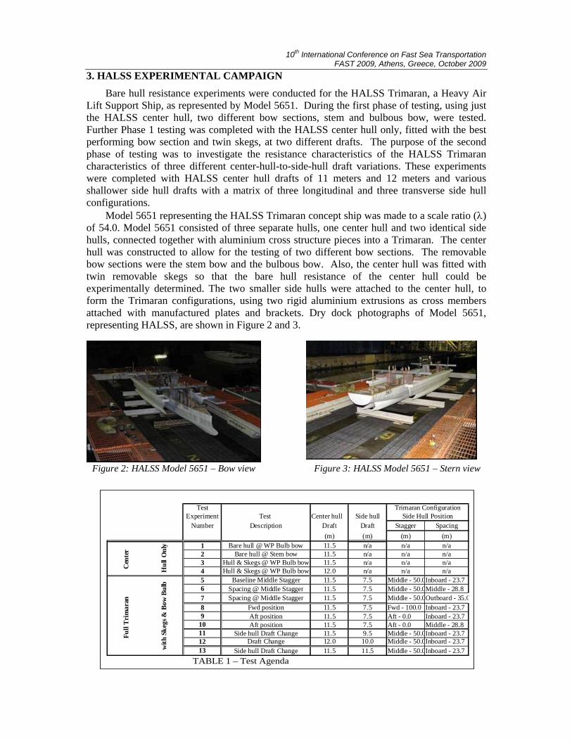
Test
Experiment Test Center hull Side hullNumber Description Draft Draft Stagger Spacing
(m) (m) (m) (m)1 Bare hull @ WP Bulb bow 11.5 n/a n/a n/a2 Bare hull @ Stem bow 11.5 n/a n/a n/a3 Hull & Skegs @ WP Bulb bow 11.5 n/a n/a n/a4 Hull & Skegs @ WP Bulb bow 12.0 n/a n/a n/a5 Baseline Middle Stagger 11.5 7.5 Middle - 50.0Inboard - 23.76 Spacing @ Middle Stagger 11.5 7.5 Middle - 50.0Middle - 28.87 Spacing @ Middle Stagger 11.5 7.5 Middle - 50.0Outboard - 35.08 Fwd position 11.5 7.5 Fwd - 100.0 Inboard - 23.79 Aft position 11.5 7.5 Aft - 0.0 Inboard - 23.7
10 Aft position 11.5 7.5 Aft - 0.0 Middle - 28.811 Side hull Draft Change 11.5 9.5 Middle - 50.0Inboard - 23.712 Draft Change 12.0 10.0 Middle - 50.0Inboard - 23.713 Side hull Draft Change 11.5 11.5 Middle - 50.0Inboard - 23.7
Trimaran ConfigurationSide Hull Position
C
ente
r
Hul
l Onl
y
Fu
ll Tr
imar
an
with
Ske
gs &
Bow
Bul
b
TABLE 1 – Test Agenda
10th International Conference on Fast Sea Transportation FAST 2009, Athens, Greece, October 2009
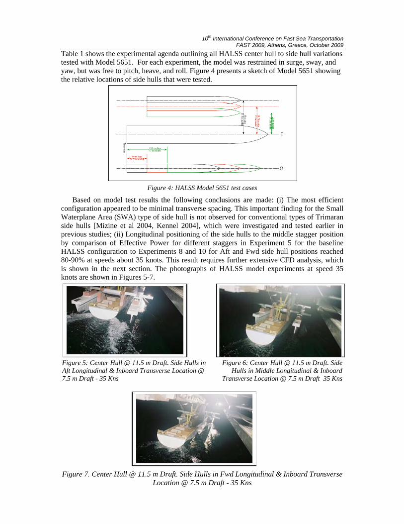
Table 1 shows the experimental agenda outlining all HALSS center hull to side hull variations tested with Model 5651. For each experiment, the model was restrained in surge, sway, and yaw, but was free to pitch, heave, and roll. Figure 4 presents a sketch of Model 5651 showing the relative locations of side hulls that were tested.
Figure 4: HALSS Model 5651 test cases
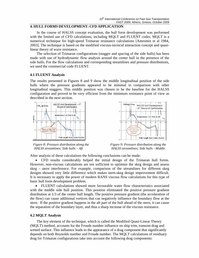
Based on model test results the following conclusions are made: (i) The most efficient configuration appeared to be minimal transverse spacing. This important finding for the Small Waterplane Area (SWA) type of side hull is not observed for conventional types of Trimaran side hulls [Mizine et al 2004, Kennel 2004], which were investigated and tested earlier in previous studies; (ii) Longitudinal positioning of the side hulls to the middle stagger position by comparison of Effective Power for different staggers in Experiment 5 for the baseline HALSS configuration to Experiments 8 and 10 for Aft and Fwd side hull positions reached 80-90% at speeds about 35 knots. This result requires further extensive CFD analysis, which is shown in the next section. The photographs of HALSS model experiments at speed 35 knots are shown in Figures 5-7.
Figure 5: Center Hull @ 11.5 m Draft. Side Hulls in Figure 6: Center Hull @ 11.5 m Draft. Side Aft Longitudinal & Inboard Transverse Location @ Hulls in Middle Longitudinal & Inboard 7.5 m Draft - 35 Kns Transverse Location @ 7.5 m Draft 35 Kns
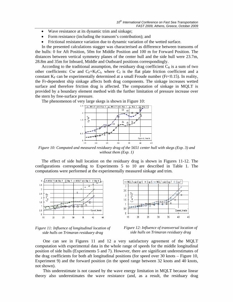
Figure 7. Center Hull @ 11.5 m Draft. Side Hulls in Fwd Longitudinal & Inboard Transverse Location @ 7.5 m Draft - 35 Kns
10th International Conference on Fast Sea Transportation FAST 2009, Athens, Greece, October 2009
4. HULL FORMS DEVELOPMENT: CFD APPLICATION
In the course of HALSS concept evaluation, the hull form development was performed with the limited use of CFD calculations, including MQLT and FLUENT codes. MQLT is a numerical technique for high-speed Trimaran resistance calculations [Amromin et al 1984, 2003]. The technique is based on the modified viscous-inviscid interaction concept and quasi-linear theory of wave resistance.
The selection of Trimaran configurations (stagger and spacing of the side hulls) has been made with use of hydrodynamic flow analysis around the center hull in the presence of the side hulls. For the flow calculations and corresponding streamlines and pressure distributions, we used the commercial code FLUENT. 4.1 FLUENT Analysis
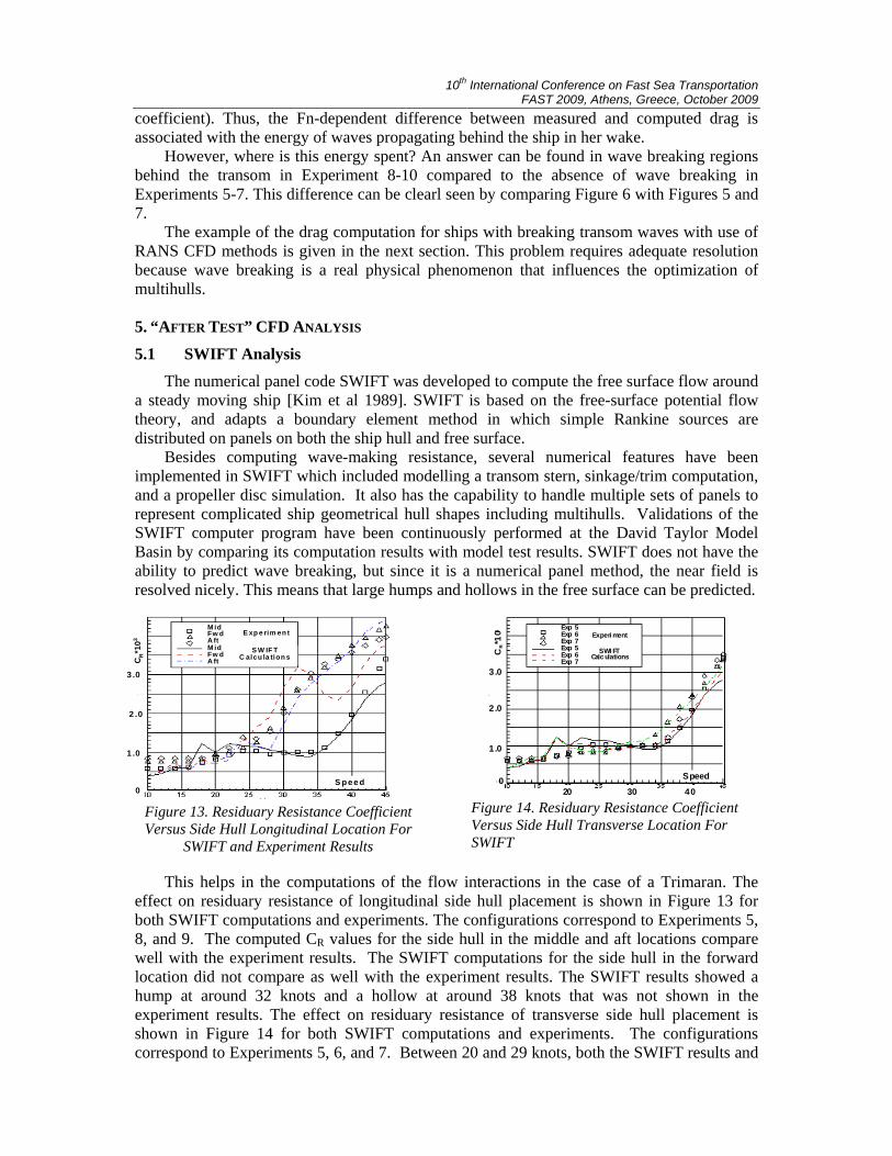
The results presented in Figures 8 and 9 show the middle longitudinal position of the side hulls where the pressure gradients appeared to be minimal in comparison with other longitudinal staggers. This middle position was chosen to be the baseline for the HALSS configuration and proved to be very efficient from the minimum resistance point of view as described in the next section.
Figure 8: Pressure distribution along the Figure 9: Pressure distribution along the HALSS streamlines; Side hulls – Aft HALSS streamlines; Side hulls - Middle
After analysis of these calculations the following conclusions can be made: • CFD results considerably helped the initial design of the Trimaran hull forms.
However, non-viscous calculations are not sufficient to optimize the skeg design and assess skeg – stern interference. For example, comparison of the streamlines for different skeg designs showed very little difference which makes stern-skeg design improvement difficult. It is necessary to apply the power of modern RANS viscous flow calculations for this type of basic hull form development problem.
• FLUENT calculations showed more favourable water flow characteristics associated with the middle side hull position. This position eliminated the positive pressure gradient distribution at 1/3 of the center hull length. The positive pressure gradient (the acceleration of the flow) can cause additional vortices that can negatively influence the boundary flow at the stern. If the positive gradient happens in the aft part of the hull ahead of the stern, it can cause the separation of the boundary layer, and thus a sharp increase of the viscous resistance.
4.2 MQLT Analysis
The key element of the technique, which is called the Modified Quasi-Linear Theory (MQLT) method, accounts for the Froude number influence on ship trim, transom drag and wetted surface. This influence leads to the appearance of a drag component that significantly depends on both Reynolds number and Froude number. The MQLT calculations of residuary drag for Trimaran configurations take into account the following drag components:
10th International Conference on Fast Sea Transportation FAST 2009, Athens, Greece, October 2009
• Wave resistance at its dynamic trim and sinkage; • Form resistance (including the transom’s contribution); and • Frictional resistance variation due to dynamic variation of the wetted surface. In the presented calculations stagger was characterised as difference between transoms of
the hulls: 0 for Aft Position, 50m for Middle Position and 100 m for Forward Position. The distances between vertical symmetry planes of the center hull and the side hull were 23.7m, 28.8m and 35m for Inboard, Middle and Outboard positions correspondingly.
According to the traditional assumption, the residuary drag coefficient CR is a sum of two other coefficients: Cw and CF=KFCf, where Cf is the flat plate friction coefficient and a constant KF can be experimentally determined at a small Froude number (Fr<0.15). In reality, the Fr-dependent ship sinkage affects both drag components. The sinkage increases wetted surface and therefore friction drag is affected. The computation of sinkage in MQLT is provided by a boundary element method with the further limitation of pressure increase over the stern by free-surface pressure.
The phenomenon of very large skegs is shown in Figure 10:
Figure 10: Computed and measured residuary drag of the 5651 center hull with skegs (Exp. 3) and
without them (Exp. 1) The effect of side hull location on the residuary drag is shown in Figures 11-12. The
configurations corresponding to Experiments 5 to 10 are described in Table 1. The computations were performed at the experimentally measured sinkage and trim.
Figure 11: Influence of longitudinal location of side hulls on Trimaran residuary drag
Figure 12: Influence of transversal location of side hulls on Trimaran residuary drag
One can see in Figures 11 and 12 a very satisfactory agreement of the MQLT
computation with experimental data in the whole range of speeds for the middle longitudinal position of side hulls (Experiments 5 and 7). However, there are significant underestimates of the drag coefficients for both aft longitudinal positions (for speed over 30 knots – Figure 10, Experiment 9) and the forward position (in the speed range between 32 knots and 40 knots, not shown).
This underestimate is not caused by the wave energy limitation in MQLT because linear theory also underestimates the wave resistance (and, as a result, the residuary drag
10th International Conference on Fast Sea Transportation FAST 2009, Athens, Greece, October 2009
coefficient). Thus, the Fn-dependent difference between measured and computed drag is associated with the energy of waves propagating behind the ship in her wake.
However, where is this energy spent? An answer can be found in wave breaking regions behind the transom in Experiment 8-10 compared to the absence of wave breaking in Experiments 5-7. This difference can be clearl seen by comparing Figure 6 with Figures 5 and 7.
The example of the drag computation for ships with breaking transom waves with use of RANS CFD methods is given in the next section. This problem requires adequate resolution because wave breaking is a real physical phenomenon that influences the optimization of multihulls.
5. “AFTER TEST” CFD ANALYSIS
5.1 SWIFT Analysis
The numerical panel code SWIFT was developed to compute the free surface flow around a steady moving ship [Kim et al 1989]. SWIFT is based on the free-surface potential flow theory, and adapts a boundary element method in which simple Rankine sources are distributed on panels on both the ship hull and free surface.
Besides computing wave-making resistance, several numerical features have been implemented in SWIFT which included modelling a transom stern, sinkage/trim computation, and a propeller disc simulation. It also has the capability to handle multiple sets of panels to represent complicated ship geometrical hull shapes including multihulls. Validations of the SWIFT computer program have been continuously performed at the David Taylor Model Basin by comparing its computation results with model test results. SWIFT does not have the ability to predict wave breaking, but since it is a numerical panel method, the near field is resolved nicely. This means that large humps and hollows in the free surface can be predicted.
Figure 13. Residuary Resistance Coefficient Versus Side Hull Longitudinal Location For
SWIFT and Experiment Results
Figure 14. Residuary Resistance Coefficient Versus Side Hull Transverse Location For SWIFT
This helps in the computations of the flow interactions in the case of a Trimaran. The effect on residuary resistance of longitudinal side hull placement is shown in Figure 13 for both SWIFT computations and experiments. The configurations correspond to Experiments 5, 8, and 9. The computed CR values for the side hull in the middle and aft locations compare well with the experiment results. The SWIFT computations for the side hull in the forward location did not compare as well with the experiment results. The SWIFT results showed a hump at around 32 knots and a hollow at around 38 knots that was not shown in the experiment results. The effect on residuary resistance of transverse side hull placement is shown in Figure 14 for both SWIFT computations and experiments. The configurations correspond to Experiments 5, 6, and 7. Between 20 and 29 knots, both the SWIFT results and
S pee d0
1 .0
2 .0
3 .0
M id Fw d A ftM id Fw d A ft
E xp e rim en t
S W IF TC alcu la tion sC
R*1
03
Speed
Exp 5 Exp 6 Exp 7Exp 5 Exp 6 Exp 7
Experi ment
SWI FT Calc ulations
3020 400
1.0
2.0
3.0
CR*1
03
10th International Conference on Fast Sea Transportation FAST 2009, Athens, Greece, October 2009
the experiment results show that the most inboard location had the highest residuary resistance, and between 30 and 44 knots had the lowest residuary resistance. The ranking in the residuary resistance from SWIFT and experiments between the intermediate and outboard locations did not agree, however resistance variations were small. Additional details of SWIFT calculations for HALSS are in [Mizine, Karafiath 2008]. 5.2 THE ISIS-CFD RANSE Analysis
The unsteady hydrodynamic RANSE with free surface computations are performed using FINE™/Marine software. The mesh generator HEXPRESS included in FINE™/Marine offers hex-pure unstructured mesh allowing complex geometry meshing in affordable turn-around time. The ISIS-CFD RANSE flow solver was developed by the CFD Department of the Fluid Mechanics Laboratory at Centrale Nantes). Turbulent flow is simulated by solving the incompressible unsteady Reynolds-averaged Navier-Stokes equations (RANS). The solver is based on the finite volume method to build the spatial discretization of the transport equations. The face-based method is generalized to two-dimensional, rotationally symmetric, or three-dimensional unstructured meshes for which non-overlapping control volumes are bounded by an arbitrary number of constitutive faces. The velocity field is obtained from the momentum conservation equations and the pressure field is extracted from the mass conservation constraint, or continuity equation, transformed into a pressure equation. In the case of turbulent flows, additional transport equations for modelled variables are discretized and solved using the same principles. Several turbulence models ranging from one-equation model to Reynolds stress transport model are implemented in ISIS-CFD. Free-surface flow is simulated with an interface capturing approach. Both non-miscible flow phases (air and water) are modelled through the use of a conservation equation for a volume fraction of phase. The location of the free surface corresponds to the iso-surface a=0.5. To avoid any smearing of the interface, the volume fraction transport equations should be discretized with specific compressive discretization schemes to ensure the accuracy and sharpness of the interface. Some more details are given in [Queutey and Visonneau 2007]. 5.2.1 Computational characteristics
For symmetry considerations, only Y>0 part of the model is meshed with the help of the HEXPRESS(TM) automatic grid generator. Considering the model scale Reynolds numbers, Table 1, the y+~30 constraint on wall functions requires meshes of about 2.6M points (hull+skeg+side hulls). A typical run on a 10 processors IBM Power6 cluster takes about 6 hours to reach a well established solution with a time step of 0.02s for 20s of simulation. EASM anisotropic turbulence model is used for all the computations.
Speed (FS) 25 knots 30 knots 32 knots 35 knots 40 knots
Speed (MS) 1.7485 m/s 2.0968 m/s 2.2419 m/s 2.4477 m/s 2.8006 m/s
Froude 0.241 0.289 0.309 0.337 0.386
Reynolds (MS) 9.78 106 11.73 106 12.54 106 13.69 106 15.66 106
Lpp(MS) = 5.367m, Lpp(FS)=289.8m, Lpp(MS,SideH)=3.271m
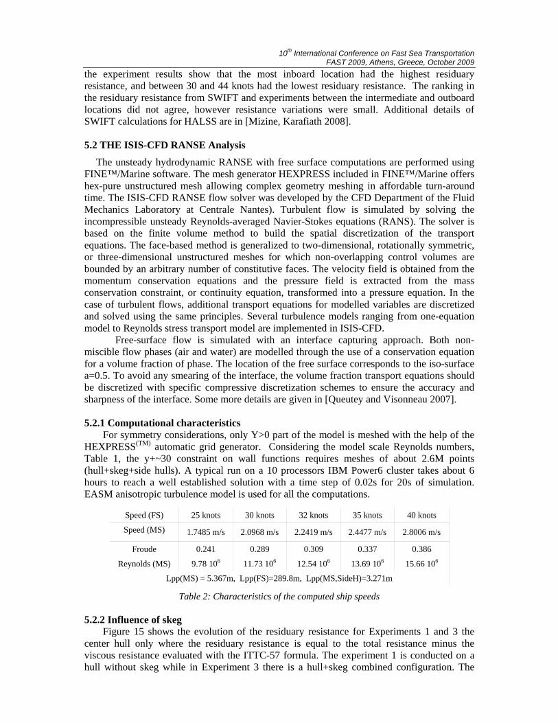
Table 2: Characteristics of the computed ship speeds 5.2.2 Influence of skeg
Figure 15 shows the evolution of the residuary resistance for Experiments 1 and 3 the center hull only where the residuary resistance is equal to the total resistance minus the viscous resistance evaluated with the ITTC-57 formula. The experiment 1 is conducted on a hull without skeg while in Experiment 3 there is a hull+skeg combined configuration. The
10th International Conference on Fast Sea Transportation FAST 2009, Athens, Greece, October 2009
influence of the skeg on the measured residuary resistance is spectacular, especially for speeds ranging from 30 to 40 knots. In order to analyze the physical origins of this influence, detailed computations have been performed with ISIS-CFD on configurations 1 and 3 for various speeds ranging from 25 to 40 knots.
The computed residuary resistance Cr is shown in the same Figure 15 where one can notice a very satisfactory agreement between measurements and computations. It confirms the increase of resistance coming from the addition of a skeg. It confirms the reliability of a computational procedure based on ISIS-CFD.
Figure 15. Evolution of the residuary resistance with ship speed. Experiments - lines with small symbols; Computations (Exp. 1 and 3 only) - Large empty symbols.
5.2.2.1 Forces
Force coefficients are expressed from the wetted surface based on numerical model, 3.24m² and 3.60m², for model scale Experiments 1 and 3, respectively. Speed is indicated for full scale in knots and in m/s for model scale.
Table 3 shows for various speeds the viscous, pressure, total and residuary resistance
coefficients. First of all, one can notice that the viscous resistance is way larger than pressure resistance for both configurations. However, for a speed of 35 knots, for instance, the pressure resistance represents 28% of the total resistance with out skeg and 41% for the hull with skeg. Although the viscous resistance is not strongly affected by the presence of skegs, the pressure resistance may be multiplied by a factor greater than 2 when skegs are included. One can also notice the relatively good agreement between the predicted viscous resistance and the values provide by the ITTC-57 formula. Therefore, the main origin of the increased resistance is the modification of the pressure field and its consequences on the resistance. It is interesting to notice here that an evaluation of the skeg influence with a simple double-body computation would not have revealed the same information.
10th International Conference on Fast Sea Transportation FAST 2009, Athens, Greece, October 2009
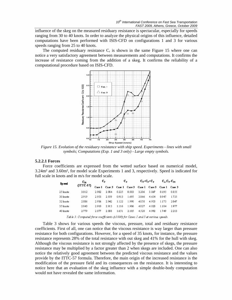
5.2.2.2 Wave elevations
The large difference in terms of resistance between Experiments 1 and 3 is related with a completely different behaviour of the free-surface in the last quarter of the hull as illustrated by Figures 16 and 17 The addition of a skeg and the related strong modification of the pressure field result into a local suction of the free-surface leading to a local breaking wave, which dramatically increases the resistance.
Figure 16: Free-surface elevations for Exp. 1 (top) and Exp. 3 (bottom) at 40 knots.
Difference on free-surface starts early upstream at 0.8Lpp near the hull surface (see
global view in Figure 16) and, after 0.95Lpp, the configuration Experiment 3 with skegs exhibits a strong breaking wave associated with a spectacular reduction of the wetted surface: see Figure 17 where the wave breaking system is clearly detected.
Figure 17: Free-surface elevation close to the stern of the hull for Exp. 1 (top) and Exp. 3
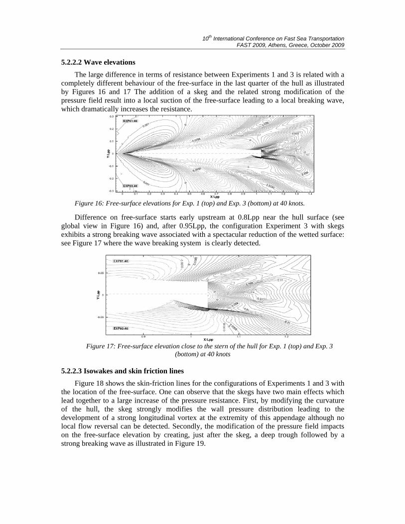
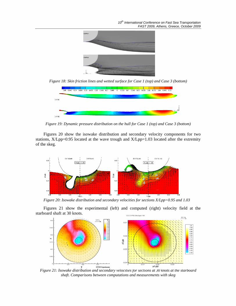
(bottom) at 40 knots 5.2.2.3 Isowakes and skin friction lines
Figure 18 shows the skin-friction lines for the configurations of Experiments 1 and 3 with the location of the free-surface. One can observe that the skegs have two main effects which lead together to a large increase of the pressure resistance. First, by modifying the curvature of the hull, the skeg strongly modifies the wall pressure distribution leading to the development of a strong longitudinal vortex at the extremity of this appendage although no local flow reversal can be detected. Secondly, the modification of the pressure field impacts on the free-surface elevation by creating, just after the skeg, a deep trough followed by a strong breaking wave as illustrated in Figure 19.
10th International Conference on Fast Sea Transportation FAST 2009, Athens, Greece, October 2009
Figure 18: Skin friction lines and wetted surface for Case 1 (top) and Case 3 (bottom)
Figure 19: Dynamic pressure distribution on the hull for Case 1 (top) and Case 3 (bottom)
Figures 20 show the isowake distribution and secondary velocity components for two
stations, X/Lpp=0.95 located at the wave trough and X/Lpp=1.03 located after the extremity of the skeg.
Figure 20: Isowake distribution and secondary velocities for sections X/Lpp=0.95 and 1.03 Figures 21 show the experimental (left) and computed (right) velocity field at the
starboard shaft at 30 knots.
Figure 21: Isowake distribution and secondary velocities for sections at 30 knots at the starboard shaft. Comparisons between computations and measurements with skeg
10th International Conference on Fast Sea Transportation FAST 2009, Athens, Greece, October 2009
Although one can not notice any difference near the vertical symmetry plane, the main effect of the skeg is to increase the horizontal velocity component V (correlated with favourable Y-pressure gradient) so that the free-surface level moves down to maintain the incompressibility constraint. Finally, this results into a generation of a strong longitudinal vortex and a violent breaking wave, both phenomena contributing to a significant increase of the pressure resistance.
One can clearly see on the isowake distribution the wake of the skeg and two contra rotative longitudinal vortices in the computations which are hardly visible in the measurements with the measurement accuracy. However, the good agreement between these local flow field measurements and the viscous simulations is very reassuring. 5.2.3 Influence of transverse location of side hulls
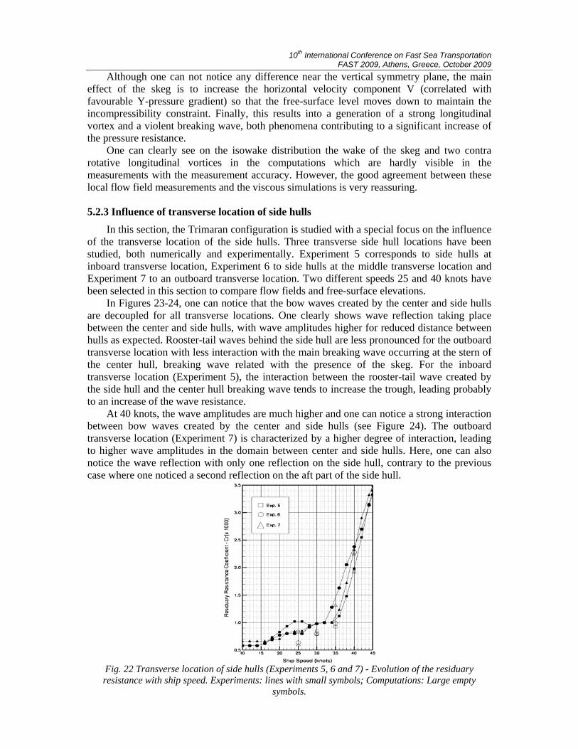
In this section, the Trimaran configuration is studied with a special focus on the influence of the transverse location of the side hulls. Three transverse side hull locations have been studied, both numerically and experimentally. Experiment 5 corresponds to side hulls at inboard transverse location, Experiment 6 to side hulls at the middle transverse location and Experiment 7 to an outboard transverse location. Two different speeds 25 and 40 knots have been selected in this section to compare flow fields and free-surface elevations.
In Figures 23-24, one can notice that the bow waves created by the center and side hulls are decoupled for all transverse locations. One clearly shows wave reflection taking place between the center and side hulls, with wave amplitudes higher for reduced distance between hulls as expected. Rooster-tail waves behind the side hull are less pronounced for the outboard transverse location with less interaction with the main breaking wave occurring at the stern of the center hull, breaking wave related with the presence of the skeg. For the inboard transverse location (Experiment 5), the interaction between the rooster-tail wave created by the side hull and the center hull breaking wave tends to increase the trough, leading probably to an increase of the wave resistance.
At 40 knots, the wave amplitudes are much higher and one can notice a strong interaction between bow waves created by the center and side hulls (see Figure 24). The outboard transverse location (Experiment 7) is characterized by a higher degree of interaction, leading to higher wave amplitudes in the domain between center and side hulls. Here, one can also notice the wave reflection with only one reflection on the side hull, contrary to the previous case where one noticed a second reflection on the aft part of the side hull.
Fig. 22 Transverse location of side hulls (Experiments 5, 6 and 7) - Evolution of the residuary resistance with ship speed. Experiments: lines with small symbols; Computations: Large empty
symbols.
10th International Conference on Fast Sea Transportation FAST 2009, Athens, Greece, October 2009
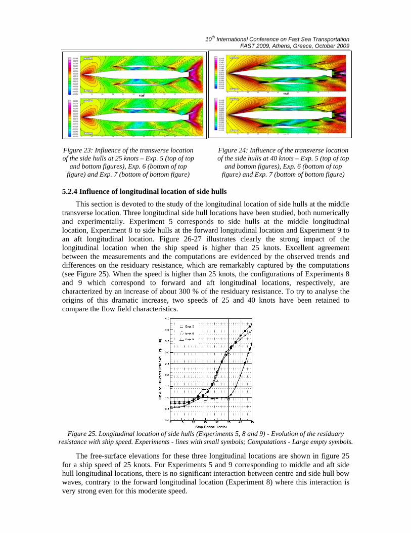
Figure 23: Influence of the transverse location of the side hulls at 25 knots – Exp. 5 (top of top
and bottom figures), Exp. 6 (bottom of top figure) and Exp. 7 (bottom of bottom figure)
Figure 24: Influence of the transverse location of the side hulls at 40 knots – Exp. 5 (top of top
and bottom figures), Exp. 6 (bottom of top figure) and Exp. 7 (bottom of bottom figure)
5.2.4 Influence of longitudinal location of side hulls
This section is devoted to the study of the longitudinal location of side hulls at the middle transverse location. Three longitudinal side hull locations have been studied, both numerically and experimentally. Experiment 5 corresponds to side hulls at the middle longitudinal location, Experiment 8 to side hulls at the forward longitudinal location and Experiment 9 to an aft longitudinal location. Figure 26-27 illustrates clearly the strong impact of the longitudinal location when the ship speed is higher than 25 knots. Excellent agreement between the measurements and the computations are evidenced by the observed trends and differences on the residuary resistance, which are remarkably captured by the computations (see Figure 25). When the speed is higher than 25 knots, the configurations of Experiments 8 and 9 which correspond to forward and aft longitudinal locations, respectively, are characterized by an increase of about 300 % of the residuary resistance. To try to analyse the origins of this dramatic increase, two speeds of 25 and 40 knots have been retained to compare the flow field characteristics.
Figure 25. Longitudinal location of side hulls (Experiments 5, 8 and 9) - Evolution of the residuary resistance with ship speed. Experiments - lines with small symbols; Computations - Large empty symbols.
The free-surface elevations for these three longitudinal locations are shown in figure 25
for a ship speed of 25 knots. For Experiments 5 and 9 corresponding to middle and aft side hull longitudinal locations, there is no significant interaction between centre and side hull bow waves, contrary to the forward longitudinal location (Experiment 8) where this interaction is very strong even for this moderate speed.
10th International Conference on Fast Sea Transportation FAST 2009, Athens, Greece, October 2009
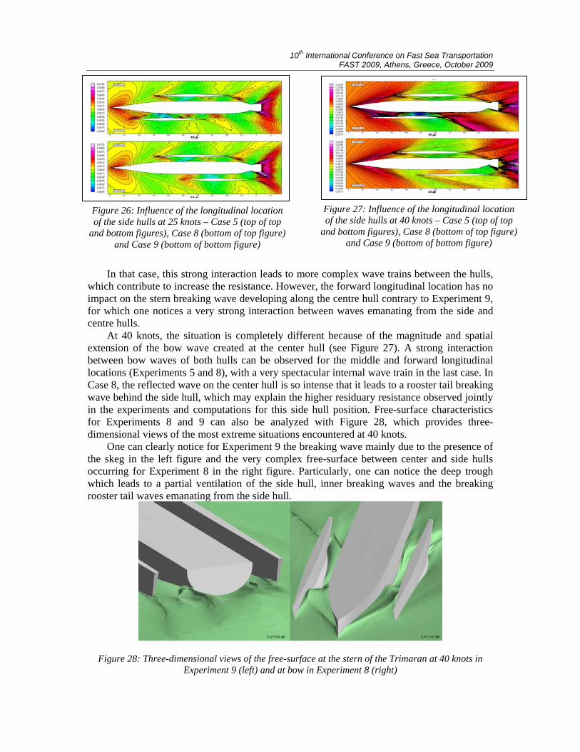
Figure 26: Influence of the longitudinal location of the side hulls at 25 knots – Case 5 (top of top
and bottom figures), Case 8 (bottom of top figure) and Case 9 (bottom of bottom figure)
Figure 27: Influence of the longitudinal location of the side hulls at 40 knots – Case 5 (top of top
and bottom figures), Case 8 (bottom of top figure) and Case 9 (bottom of bottom figure)
In that case, this strong interaction leads to more complex wave trains between the hulls, which contribute to increase the resistance. However, the forward longitudinal location has no impact on the stern breaking wave developing along the centre hull contrary to Experiment 9, for which one notices a very strong interaction between waves emanating from the side and centre hulls.
At 40 knots, the situation is completely different because of the magnitude and spatial extension of the bow wave created at the center hull (see Figure 27). A strong interaction between bow waves of both hulls can be observed for the middle and forward longitudinal locations (Experiments 5 and 8), with a very spectacular internal wave train in the last case. In Case 8, the reflected wave on the center hull is so intense that it leads to a rooster tail breaking wave behind the side hull, which may explain the higher residuary resistance observed jointly in the experiments and computations for this side hull position. Free-surface characteristics for Experiments 8 and 9 can also be analyzed with Figure 28, which provides three-dimensional views of the most extreme situations encountered at 40 knots.
One can clearly notice for Experiment 9 the breaking wave mainly due to the presence of the skeg in the left figure and the very complex free-surface between center and side hulls occurring for Experiment 8 in the right figure. Particularly, one can notice the deep trough which leads to a partial ventilation of the side hull, inner breaking waves and the breaking rooster tail waves emanating from the side hull.
Figure 28: Three-dimensional views of the free-surface at the stern of the Trimaran at 40 knots in Experiment 9 (left) and at bow in Experiment 8 (right)
10th International Conference on Fast Sea Transportation FAST 2009, Athens, Greece, October 2009
5.2.5 Study of wave interference without the skegs
Successful validation of ISIS-CFD RANSE calculations showed significant wave interference first of all depending on longitudinal position of the side hulls. This influence is very favourable (Experiments 5-7), when the side hulls are in the middle position, and very unfavourable, when the side hulls are in the aft (Experiments 9-10) or forward (Experiment 8) positions. The negative effect of center hull skegs was also found and quantatively measured. An important design question is whether wave interference is the product of center hull skegs and the related strong modification of the pressure field leading to a local breaking wave, or is wave interference the fundamental phenomenon in this particular HALSS case for center hull with and without skegs, depending only or mostly on the longitudinal position of the side hulls.
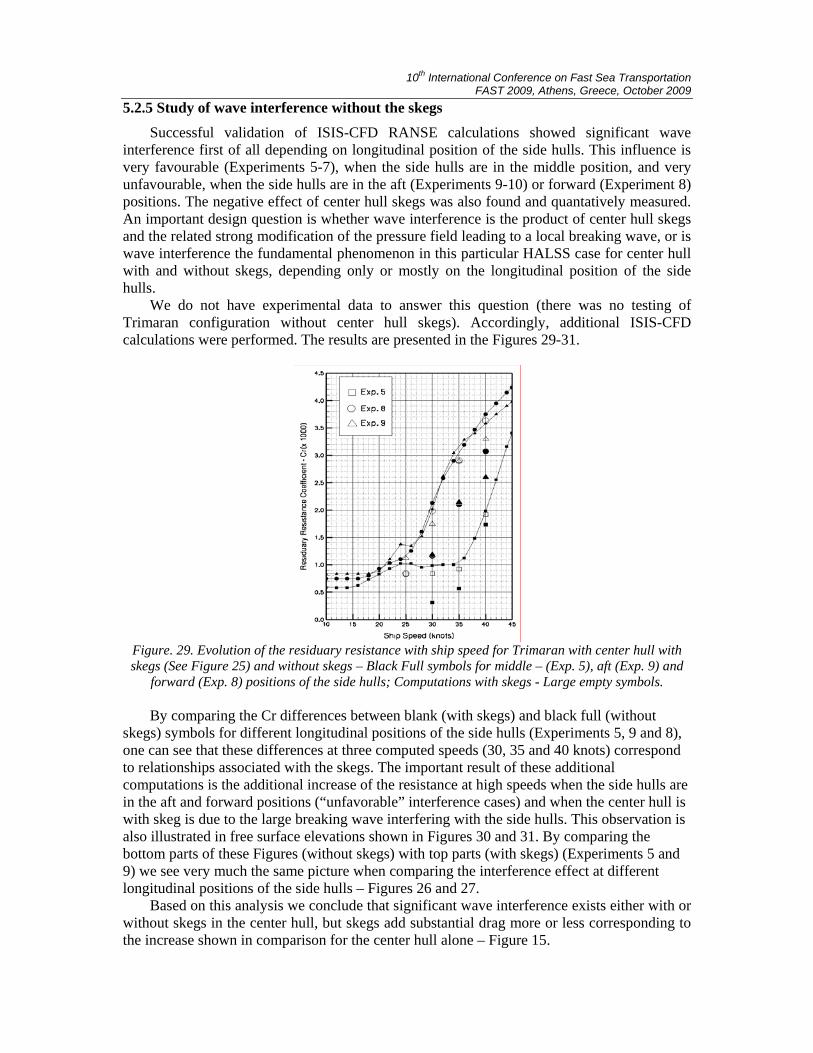
We do not have experimental data to answer this question (there was no testing of Trimaran configuration without center hull skegs). Accordingly, additional ISIS-CFD calculations were performed. The results are presented in the Figures 29-31.
Figure. 29. Evolution of the residuary resistance with ship speed for Trimaran with center hull with skegs (See Figure 25) and without skegs – Black Full symbols for middle – (Exp. 5), aft (Exp. 9) and
forward (Exp. 8) positions of the side hulls; Computations with skegs - Large empty symbols.
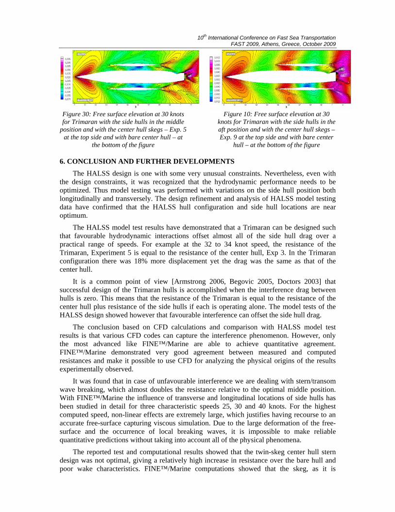
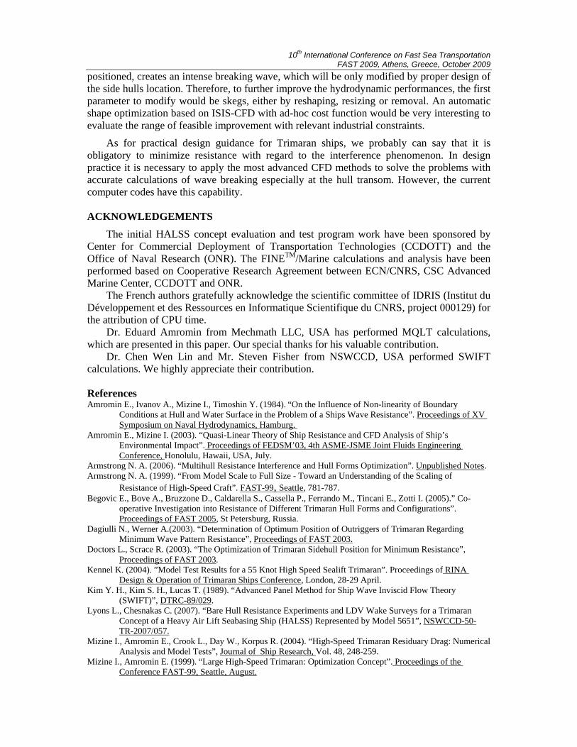
By comparing the Cr differences between blank (with skegs) and black full (without skegs) symbols for different longitudinal positions of the side hulls (Experiments 5, 9 and 8), one can see that these differences at three computed speeds (30, 35 and 40 knots) correspond to relationships associated with the skegs. The important result of these additional computations is the additional increase of the resistance at high speeds when the side hulls are in the aft and forward positions (“unfavorable” interference cases) and when the center hull is with skeg is due to the large breaking wave interfering with the side hulls. This observation is also illustrated in free surface elevations shown in Figures 30 and 31. By comparing the bottom parts of these Figures (without skegs) with top parts (with skegs) (Experiments 5 and 9) we see very much the same picture when comparing the interference effect at different longitudinal positions of the side hulls – Figures 26 and 27.
Based on this analysis we conclude that significant wave interference exists either with or without skegs in the center hull, but skegs add substantial drag more or less corresponding to the increase shown in comparison for the center hull alone – Figure 15.
10th International Conference on Fast Sea Transportation FAST 2009, Athens, Greece, October 2009
Figure 30: Free surface elevation at 30 knots for Trimaran with the side hulls in the middle
position and with the center hull skegs – Exp. 5 at the top side and with bare center hull – at
the bottom of the figure
Figure 10: Free surface elevation at 30
knots for Trimaran with the side hulls in the aft position and with the center hull skegs – Exp. 9 at the top side and with bare center
hull – at the bottom of the figure 6. CONCLUSION AND FURTHER DEVELOPMENTS
The HALSS design is one with some very unusual constraints. Nevertheless, even with the design constraints, it was recognized that the hydrodynamic performance needs to be optimized. Thus model testing was performed with variations on the side hull position both longitudinally and transversely. The design refinement and analysis of HALSS model testing data have confirmed that the HALSS hull configuration and side hull locations are near optimum.
The HALSS model test results have demonstrated that a Trimaran can be designed such that favourable hydrodynamic interactions offset almost all of the side hull drag over a practical range of speeds. For example at the 32 to 34 knot speed, the resistance of the Trimaran, Experiment 5 is equal to the resistance of the center hull, Exp 3. In the Trimaran configuration there was 18% more displacement yet the drag was the same as that of the center hull.
It is a common point of view [Armstrong 2006, Begovic 2005, Doctors 2003] that successful design of the Trimaran hulls is accomplished when the interference drag between hulls is zero. This means that the resistance of the Trimaran is equal to the resistance of the center hull plus resistance of the side hulls if each is operating alone. The model tests of the HALSS design showed however that favourable interference can offset the side hull drag.
The conclusion based on CFD calculations and comparison with HALSS model test results is that various CFD codes can capture the interference phenomenon. However, only the most advanced like FINE™/Marine are able to achieve quantitative agreement. FINE™/Marine demonstrated very good agreement between measured and computed resistances and make it possible to use CFD for analyzing the physical origins of the results experimentally observed.
It was found that in case of unfavourable interference we are dealing with stern/transom wave breaking, which almost doubles the resistance relative to the optimal middle position. With FINE™/Marine the influence of transverse and longitudinal locations of side hulls has been studied in detail for three characteristic speeds 25, 30 and 40 knots. For the highest computed speed, non-linear effects are extremely large, which justifies having recourse to an accurate free-surface capturing viscous simulation. Due to the large deformation of the free-surface and the occurrence of local breaking waves, it is impossible to make reliable quantitative predictions without taking into account all of the physical phenomena.
The reported test and computational results showed that the twin-skeg center hull stern design was not optimal, giving a relatively high increase in resistance over the bare hull and poor wake characteristics. FINE™/Marine computations showed that the skeg, as it is
10th International Conference on Fast Sea Transportation FAST 2009, Athens, Greece, October 2009
positioned, creates an intense breaking wave, which will be only modified by proper design of the side hulls location. Therefore, to further improve the hydrodynamic performances, the first parameter to modify would be skegs, either by reshaping, resizing or removal. An automatic shape optimization based on ISIS-CFD with ad-hoc cost function would be very interesting to evaluate the range of feasible improvement with relevant industrial constraints.
As for practical design guidance for Trimaran ships, we probably can say that it is obligatory to minimize resistance with regard to the interference phenomenon. In design practice it is necessary to apply the most advanced CFD methods to solve the problems with accurate calculations of wave breaking especially at the hull transom. However, the current computer codes have this capability.
ACKNOWLEDGEMENTS
The initial HALSS concept evaluation and test program work have been sponsored by Center for Commercial Deployment of Transportation Technologies (CCDOTT) and the Office of Naval Research (ONR). The FINETM/Marine calculations and analysis have been performed based on Cooperative Research Agreement between ECN/CNRS, CSC Advanced Marine Center, CCDOTT and ONR.
The French authors gratefully acknowledge the scientific committee of IDRIS (Institut du Développement et des Ressources en Informatique Scientifique du CNRS, project 000129) for the attribution of CPU time.
Dr. Eduard Amromin from Mechmath LLC, USA has performed MQLT calculations, which are presented in this paper. Our special thanks for his valuable contribution.
Dr. Chen Wen Lin and Mr. Steven Fisher from NSWCCD, USA performed SWIFT calculations. We highly appreciate their contribution.
References Amromin E., Ivanov A., Mizine I., Timoshin Y. (1984). “On the Influence of Non-linearity of Boundary
Conditions at Hull and Water Surface in the Problem of a Ships Wave Resistance”. Proceedings of XV Symposium on Naval Hydrodynamics, Hamburg.
Amromin E., Mizine I. (2003). “Quasi-Linear Theory of Ship Resistance and CFD Analysis of Ship’s Environmental Impact”. Proceedings of FEDSM’03, 4th ASME-JSME Joint Fluids Engineering Conference, Honolulu, Hawaii, USA, July.
Armstrong N. A. (2006). “Multihull Resistance Interference and Hull Forms Optimization”. Unpublished Notes. Armstrong N. A. (1999). “From Model Scale to Full Size - Toward an Understanding of the Scaling of
Resistance of High-Speed Craft”. FAST-99, Seattle, 781-787. Begovic E., Bove A., Bruzzone D., Caldarella S., Cassella P., Ferrando M., Tincani E., Zotti I. (2005).” Co-
operative Investigation into Resistance of Different Trimaran Hull Forms and Configurations”. Proceedings of FAST 2005, St Petersburg, Russia.
Dagiulli N., Werner A.(2003). “Determination of Optimum Position of Outriggers of Trimaran Regarding Minimum Wave Pattern Resistance”, Proceedings of FAST 2003.
Doctors L., Scrace R. (2003). “The Optimization of Trimaran Sidehull Position for Minimum Resistance”, Proceedings of FAST 2003.
Kennel K. (2004). ”Model Test Results for a 55 Knot High Speed Sealift Trimaran”. Proceedings of RINA Design & Operation of Trimaran Ships Conference, London, 28-29 April.
Kim Y. H., Kim S. H., Lucas T. (1989). “Advanced Panel Method for Ship Wave Inviscid Flow Theory (SWIFT)”, DTRC-89/029.
Lyons L., Chesnakas C. (2007). “Bare Hull Resistance Experiments and LDV Wake Surveys for a Trimaran Concept of a Heavy Air Lift Seabasing Ship (HALSS) Represented by Model 5651”, NSWCCD-50-TR-2007/057.
Mizine I., Amromin E., Crook L., Day W., Korpus R. (2004). “High-Speed Trimaran Residuary Drag: Numerical Analysis and Model Tests”, Journal of Ship Research, Vol. 48, 248-259.
Mizine I., Amromin E. (1999). “Large High-Speed Trimaran: Optimization Concept”. Proceedings of the Conference FAST-99, Seattle, August.
10th International Conference on Fast Sea Transportation FAST 2009, Athens, Greece, October 2009
Mizine I., Karafiath G. (2008). “Wave Interference in Design of Large Trimaran Ship”, International Journal of Marine Engineers, RINA, Vol. 150, Part A4, pp 57-72
Garcia P.M., Wilson R.V., Stern F. (2005). “Free Surface Flows around Ships: Progress toward Simulation of High-Speed Flows and Motions”, MECOM 2005, 151-165
Queutey, P. & Visonneau, M. (2007) ‘An Interface Capturing Method for Free-Surface Hydrodynamic Flows’, Computers & Fluids, 36(9), pp. 1481-1510.
Salgalo D., Mitmek I. (2002). “Calm Water Resistance Tests for a High Speed Trimaran, as Represented by Model 5594”, NSWCCD-50-TR-2002/002.
Yang C., Noblesse F., Lohner R., Hendrix D. (2001). “Practical CFD Application to Design of a Wave Cancellation Multihull Ship”, Proceedings of FAST 2001.
Yang C., Soto O., Lohner R., Noblesse F. (2002). „Hydrodynamic Optimization of a Trimaran“. Schifftechnik Bd. 49, Ship Technology Research, Vol. 49, pp 70-91.