
Interface Manual - LumaSense Technologies A/S
79
BB6032-13 Interface Manual 1314i Photoacoustic Gas Monitor 1412i Photoacoustic Gas Monitor 3434i SF6 Leak Detector
Transcript of Interface Manual - LumaSense Technologies A/S

BB6032-13
Interface Manual 1314i Photoacoustic Gas Monitor 1412i Photoacoustic Gas Monitor 3434i SF6 Leak Detector

Index _________________________________________________________________________________________
_________________________________________________________________________________________ BB6032-13 1314i Photoacoustic Gas Monitor LumaSense Technologies 1412i Photoacoustic Gas Monitor 3434i SF6 Leak Detector Page 2 of 79
Index Index ........................................................................................................ 2
Safety Considerations. ............................................................................ 6 Warnings! ............................................................................................. 7 Applying Power ...................................................................................... 8
Chapter 1 Physical Level of the Interface ..................................................... 9 1.1 The Monitor’s Interface Ports ....................................................... 10 1.2 The USB Interface ...................................................................... 10
1.2.1 Interconnection ..................................................................... 11 1.2.2 Interface Set-up .................................................................... 12
1.3 The Ethernet (TCP/IP) Interface ................................................... 12 1.3.1 Interconnection ..................................................................... 13 1.3.2 Interface Set-up .................................................................... 13 1.3.2 The Homepage of the Gas Monitor ........................................... 14
1.4 The RS–232 Interface ................................................................. 15 1.4.1 Interconnection ..................................................................... 17 1.4.2 Interface Set-up .................................................................... 17 1.4.3 Transmission Interrupt ........................................................... 19
Chapter 2 Interface Messages .................................................................. 20 2.1 List of Interface Messages ........................................................... 21 2.2 Message Format ......................................................................... 22 2.3 The Individual Messages .............................................................. 25
2.3.1 ACCEPT_CALIBRATION ........................................................... 25 2.3.2 ACCEPT_MESSAGE ................................................................. 25 2.3.3 ALARM_START ....................................................................... 25 2.3.4 ALARM_STOP ........................................................................ 26 2.3.5 CONTROL_SRQ ...................................................................... 26 2.3.6 CURRENT_FILTER .................................................................. 27 2.3.7 CURRENT_SETUP ................................................................... 28 2.3.8 DELETE_MEASUREMENT ......................................................... 28 2.3.9 DHCP ................................................................................... 28 2.3.10 DISPLAY_AVERAGE ................................................................ 28 2.3.11 DISPLAY_STATE .................................................................... 28 2.3.12 EXECUTE_STATE? .................................................................. 29 2.3.13 EXTENDED_CONTROL ............................................................. 29 2.3.14 IDENTIFICATION? .................................................................. 30 2.3.15 IDENTIFY? ............................................................................ 30 2.3.16 IDENTIFY? CONFIGURATION ................................................... 31 2.3.17 IP Address ............................................................................ 31 2.3.18 IP Port .................................................................................. 32 2.3.19 KEYBOARD_LOCKOUT ............................................................ 32 2.3.20 MEASURE_AIR_PRESSURE ...................................................... 32 2.3.21 MEASUREMENT_STATE? ......................................................... 33 2.3.22 OUTPUT_CALIBRATION_DATA? ................................................ 33 2.3.23 OUTPUT_MEASUREMENT? ....................................................... 34 2.3.24 OUTPUT_SETUP_DATA? .......................................................... 37 2.3.25 OUTPUT_SPECIAL_COMPILATION? ........................................... 38

Index _________________________________________________________________________________________
_________________________________________________________________________________________ BB6032-13 1314i Photoacoustic Gas Monitor LumaSense Technologies 1412i Photoacoustic Gas Monitor 3434i SF6 Leak Detector Page 3 of 79
2.3.26 PAUSE_MEASUREMENT ........................................................... 40 2.3.27 POP_UP_DISPLAY_BUFFER? .................................................... 40 2.3.28 PROTECTED IP ADDRESS ........................................................ 40 2.3.29 RECALL_MEASUREMENT ......................................................... 40 2.3.30 RELAY .................................................................................. 41 2.3.31 REMOTE_DISPLAY_BUFFER ..................................................... 41 2.3.32 RESET_COMMAND ................................................................. 41 2.3.33 RESET_STATUS_BYTE ............................................................ 42 2.3.34 RESET_SYSTEM ..................................................................... 42 2.3.35 SELF_TEST? .......................................................................... 43 2.3.36 SERVICE_REQUEST_ENABLE ................................................... 43 2.3.37 SETUP .................................................................................. 45 2.3.38 SOFTWARE_IDENTIFICATION? ................................................ 51 2.3.39 START_CALIBRATION ............................................................. 52 2.3.40 START_DELAYED_MEASUREMENT ............................................ 53 2.3.41 START_MEASUREMENT ........................................................... 53 2.3.42 STATUS_BYTE? ...................................................................... 53 2.3.43 STOP_MEASUREMENT ............................................................ 54 2.3.44 STORE_DEFAULT ................................................................... 54 2.3.45 STORE_MEASUREMENT .......................................................... 54 2.3.46 SYNCHRONIZE ...................................................................... 54 2.3.47 SYNCHRONIZED_MODE_CONTINUOUS_PUMP ........................... 55 2.3.48 SYSTEM_DISPLAY_BUFFER? .................................................... 56 2.3.49 TIME_SINCE_RESET? ............................................................. 56 2.3.50 UNPROTECT .......................................................................... 56 2.3.51 ZDLOG ................................................................................. 57
Chapter 3 Interface Character Data .......................................................... 58 3.1 List of Interface Character Data .................................................... 59
Chapter 4 Error Messages ........................................................................ 63 4.1 List of Error Messages. ................................................................ 64
Chapter 5 Code Examples ........................................................................ 68 5.1 Interface Commands to make a Sample Measurement .................... 69
5.1.1 Setup before measurement ..................................................... 69 5.1.2 Measurement sequence .......................................................... 70
Chapter 6 Multipoint Sampler 1409 commands........................................... 72 6.1 Interface to 1409 Multipoint Sampler ............................................ 73
6.1.1 Idendity ................................................................................ 73 6.1.2 Reset the 1409 ...................................................................... 73 6.1.3 Controlling the Sample valves ................................................. 73 6.1.4 Controlling the 3 way valve ..................................................... 73 6.1.5 Warning interface job ............................................................. 74 6.1.6 Error interface job .................................................................. 74
Chapter 7 Service Requests ..................................................................... 76 7.1 Introduction to Service Requests .................................................. 77 7.2 The Status Byte ......................................................................... 78 7.3 The Service Request Enable Register ............................................ 78 7.4 The Event and Event Enable Register ............................................ 78

Safety Considerations _______________________________________________________________________________________
_________________________________________________________________________________________ BB6032-13 1314i Photoacoustic Gas Monitor LumaSense Technologies 1412i Photoacoustic Gas Monitor 3434i SF6 Leak Detector Page 4 of 79
1314i Photoacoustic Gas Monitor, 1412i Photoacoustic Gas Monitor
and 3434i SF6 Leak Detector
From: 1314i Serial number: 702-130 1412i Serial number: 713-500 3434i Serial number: 952-110
April 2017

Safety Considerations _______________________________________________________________________________________
_________________________________________________________________________________________ BB6032-13 1314i Photoacoustic Gas Monitor LumaSense Technologies 1412i Photoacoustic Gas Monitor 3434i SF6 Leak Detector Page 5 of 79
Trademarks WindowsTM and ExcelTM are trademarks of Microsoft Corporation. Windows© and Access® are registered trademarks of Microsoft Corporation. Copyright © 2017, LumaSense Technologies All rights reserved. No part of this publication may be reproduced or distributed in any form, or by any means, without prior consent in writing from LumaSense Technologies, Ballerup, Denmark.
About this Interface Manual This manual describes the programming and operation of the serial and parallel interfaces of the 1314i Photoacoustic Gas Monitor, 1412i Photoacoustic Gas Monitor and 3434i SF6 Leak Detector. Although the physical aspect of cabling is touched on in this manual, it is assumed that users are familiar with the manual operation of the Gas Monitor, as described in the Instruction Manuals.
Safety Considerations _______________________________________________________________________________________
_________________________________________________________________________________________ BB6032-13 1314i Photoacoustic Gas Monitor LumaSense Technologies 1412i Photoacoustic Gas Monitor 3434i SF6 Leak Detector Page 6 of 79
Safety Considerations. The 1314i Photoacoustic Gas Monitor, 1412i Photoacoustic Gas Monitor and 3434i SF6 Leak Detector complies with:
Throughout this manual Monitor is used for above mentioned instruments.
The Monitor complies with: • EN/IEC 61010-1, 3rd Edition: Safety requirements for electrical
equipment for measurement, control and laboratory use. •
• Can/CSA-C22.2 No. 61010-1-04 - Safety Requirements for Electrical Equipment for Measurement, Control, and Laboratory Use.
• UL Std. No. 61010A-1 (3rd Edition) - Safety Requirements for
Electrical Equipment for Measurement, Control, and Laboratory Use.
SAFETY SYMBOL
The apparatus will be marked with this symbol when it is important that the user refer to the associated warning statement given below.
To ensure safe operation and retain the Monitor in safe condition, note the following: Power Cord must be detached before removing the enclosure.

Safety Considerations _______________________________________________________________________________________
_________________________________________________________________________________________ BB6032-13 1314i Photoacoustic Gas Monitor LumaSense Technologies 1412i Photoacoustic Gas Monitor 3434i SF6 Leak Detector Page 7 of 79
EXPLOSION HAZARD!
TO AVOID THE POSSIBILITY OF AN EXPLOSION; MONITORING OF FLAMMABLE GASES IN EXPLOSIVE
CONCENTRATIONS MUST NEVER BE ATTEMPTED. Never operate the Monitor in potentially explosive environments. When monitoring potentially flammable or toxic gases it is essential that: • The instrument itself is placed in a well-ventilated area outside the
potentially hazardous zone. • A sufficiently long tube is connected to the air-outlet on the back
panel so that the sampled gas is carried away to the open air or to an extraction and/or filtration unit.
• Environmental Conditions for transport and storage: Temperature: -25 to +55ºC Relative Humidity: 0 to 80% RH Atmospheric Pressure: 800 to 1060 hPa
Warnings! • Avoid water condensation in the instrument. • Switch off all equipment before connecting or disconnecting their
digital interface. Failure to do so could damage the equipment. • Do not position the equipment in a way preventing the ability to
unplug the cable on the back-panel.
• Whenever it is likely that correct function or operating safety of the apparatus has been impaired, the apparatus must be made inoperative and secured against unintended operation.
• Any adjustment, maintenance and repair of the open apparatus
under voltage must be avoided as far as possible and, if unavoidable, must be carried out only by trained personnel.
Safety Considerations _______________________________________________________________________________________
_________________________________________________________________________________________ BB6032-13 1314i Photoacoustic Gas Monitor LumaSense Technologies 1412i Photoacoustic Gas Monitor 3434i SF6 Leak Detector Page 8 of 79
• If a fault is reported by the monitor that indicates correct function of the instrument may be impaired, consult your local LumaSense Technologies representative. Under no circumstances should repair be attempted by persons not qualified in service of electronic instrumentation.
• Use of the Monitor in a manner not specified by the manufacturer
may impair the protection provided by the equipment
Applying Power
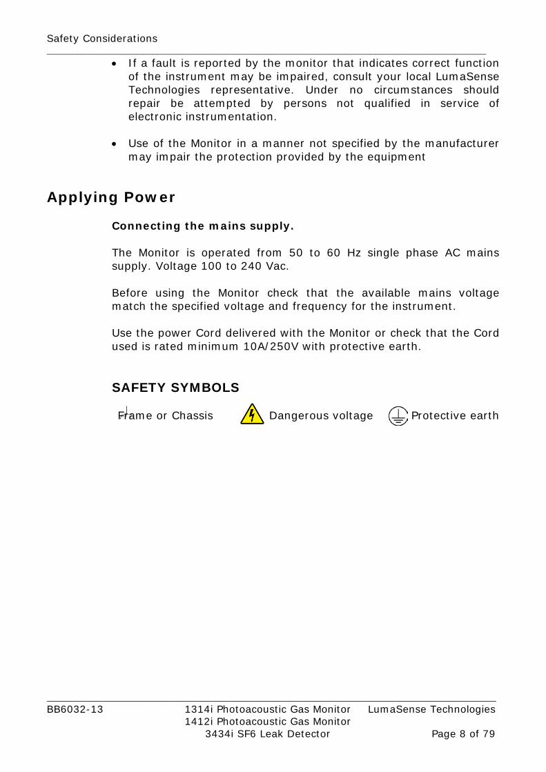
Connecting the mains supply. The Monitor is operated from 50 to 60 Hz single phase AC mains supply. Voltage 100 to 240 Vac. Before using the Monitor check that the available mains voltage match the specified voltage and frequency for the instrument. Use the power Cord delivered with the Monitor or check that the Cord used is rated minimum 10A/250V with protective earth. SAFETY SYMBOLS Frame or Chassis Dangerous voltage Protective earth

Chapter 1 _________________________________________________________________________________________
_________________________________________________________________________________________ BB6032-13 1314i Photoacoustic Gas Monitor LumaSense Technologies 1412i Photoacoustic Gas Monitor 3434i SF6 Leak Detector Page 9 of 79
Chapter 1
Physical Level of the Interface
April 2017

Chapter 1 _________________________________________________________________________________________
_________________________________________________________________________________________ BB6032-13 1314i Photoacoustic Gas Monitor LumaSense Technologies 1412i Photoacoustic Gas Monitor 3434i SF6 Leak Detector Page 10 of 79
1.1 The Monitor’s Interface Ports The interface ports, USB, Ethernet (TCP/IP) and RS-232 are located on the rear panel of the Monitor, see Fig. 1.1.
Fig. 1.1 The interface connections on the rear panel of the Monitor WARNING! Before connecting any cables to the Monitor, ensure that the power to the Monitor is turned off. Cabling to the Monitor is covered in more detail in the Instruction Manual.
1.2 The USB Interface
The USB interface is designed in accordance with the USB specification, revision 2.0 (Full-speed). It supports hot plugging and dynamic configuration of the device, meaning that Gas Monitor device can be connected to a USB cable while power is on. The USB interface of the Monitor acts as a device controller, thus it can be connected to an USB host controller (typically in a PC), through an USB cable.
Interface Connector The interface connector Fig. 1.3 is a Standard Type B USB connector. It is located on the rear panel of the Monitor as shown in Fig. 1.1. Next to interface connector the USB interface symbol is displayed, as shown in Fig. 1.2. Pin definitions are given in Table 1.1.
Chapter 1 _______________________________________________________________________________________
_________________________________________________________________________________________ BB6032-13 1314i Photoacoustic Gas Monitor LumaSense Technologies 1412i Photoacoustic Gas Monitor 3434i SF6 Leak Detector Page 11 of 79
Fig. 1.2 The USB interface symbol
Fig. 1.3 The USB interface connector of the Monitor
Table 1.1 Pin definitions of the USB interface
1.2.1 Interconnection
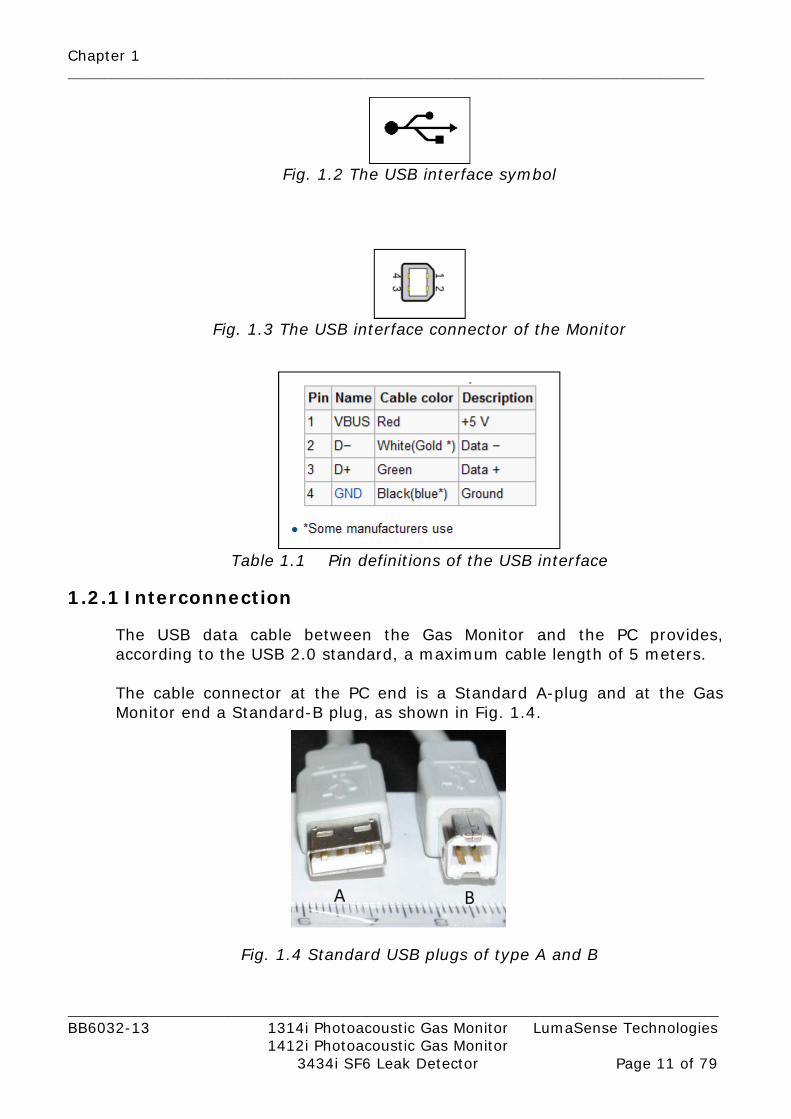
The USB data cable between the Gas Monitor and the PC provides, according to the USB 2.0 standard, a maximum cable length of 5 meters. The cable connector at the PC end is a Standard A-plug and at the Gas Monitor end a Standard-B plug, as shown in Fig. 1.4.
Fig. 1.4 Standard USB plugs of type A and B

Chapter 1 _______________________________________________________________________________________
_________________________________________________________________________________________ BB6032-13 1314i Photoacoustic Gas Monitor LumaSense Technologies 1412i Photoacoustic Gas Monitor 3434i SF6 Leak Detector Page 12 of 79
1.2.2 Interface Set-up
The interface is set-up by installing the “Lumasense 1412i USB driver” on the host PC, which communicates with the Gas Monitor. The “Lumasense 1412i USB driver” is part of the installation of the LumaSoft Gas 7810 Singlepoint and the 7870 Multipoint application software. The “Lumasense 1412i USB driver is based on the WINUSB driver from the Windows Driver Kit (WDK).
1.3 The Ethernet (TCP/IP) Interface
The Ethernet interface features a Fast Ethernet transceiver (transmitter and receiver). It is fully compliant with the IEEE 802.3u specification for Fast Ethernet at 100 Mbit/s. It automatically detects the required cable connection type and configures the connection appropriately, supporting both straight-through and crossover Ethernet (TCP/IP) cables.
Interface Connector The interface connector Fig. 1.6 is a standard RJ45 Ethernet connector. It is located on the rear panel of the Monitor as shown in Fig. 1.1. Next to interface connector, the Ethernet interface symbol is displayed, as shown in Fig. 1.5.
Fig. 1.5 The Ethernet interface symbol The Amber LED indicates that the Gas Monitor is connected to an Ethernet network.
Chapter 1 _______________________________________________________________________________________
_________________________________________________________________________________________ BB6032-13 1314i Photoacoustic Gas Monitor LumaSense Technologies 1412i Photoacoustic Gas Monitor 3434i SF6 Leak Detector Page 13 of 79
The Green Led indicates data activity on the Ethernet connection.
Fig. 1.6 The Ethernet interface connector of the Monitor
1.3.1 Interconnection
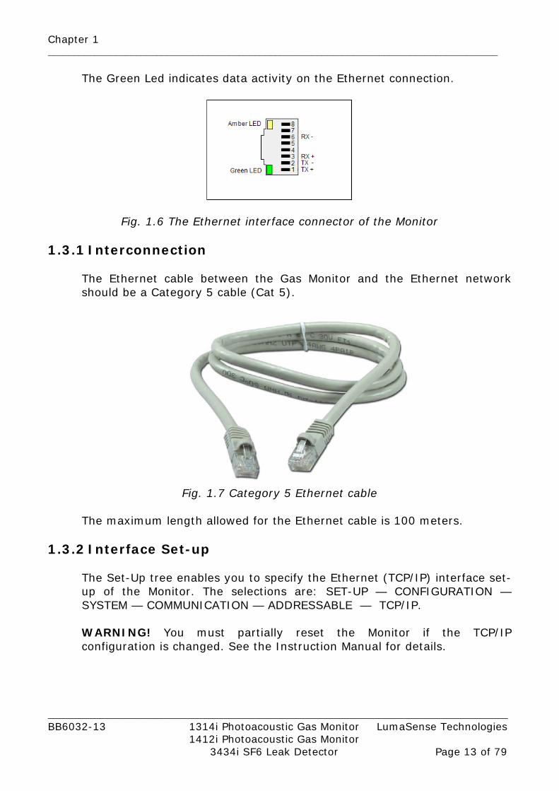
The Ethernet cable between the Gas Monitor and the Ethernet network should be a Category 5 cable (Cat 5).
Fig. 1.7 Category 5 Ethernet cable
The maximum length allowed for the Ethernet cable is 100 meters.
1.3.2 Interface Set-up
The Set-Up tree enables you to specify the Ethernet (TCP/IP) interface set-up of the Monitor. The selections are: SET-UP — CONFIGURATION — SYSTEM — COMMUNICATION — ADDRESSABLE — TCP/IP. WARNING! You must partially reset the Monitor if the TCP/IP configuration is changed. See the Instruction Manual for details.

Chapter 1 _______________________________________________________________________________________
_________________________________________________________________________________________ BB6032-13 1314i Photoacoustic Gas Monitor LumaSense Technologies 1412i Photoacoustic Gas Monitor 3434i SF6 Leak Detector Page 14 of 79
IS 1412i/1314i/3434i’s IP ADDRESS SET BY DHCP? This determines whether the IP address of the Monitor is fixed or if the IP address is set by DHCP. DHCP is a server on the Ethernet network who automatically assigns IP addresses to Ethernet devices on the network.
1412i/1314i/3434i’s IP ADDRESS If the IP address is not set by a DHCP server (as selected in the previous setup) the IP address of the Monitor can be entered manually.
1412i/1314i/3434i’s IP PORT NUMBER: The IP port number where communication between the Monitor and host PC goes through. The default port number is 23.
PROTECTED IP ADDRESS This sets the IP address of the host PC, who is allowed to communicate with the Gas Monitor. If the value is 000.000.000.000 the any host PC is allowed to communicate with the Gas Monitor.
CURRENT IP ADDRESS This is shown if the IP address is set by the DHCP server. It tells which IP address have been assigned to the Gas Monitor by the DHCP server.
1.3.2 The Homepage of the Gas Monitor The homepage of the Monitor can be displayed if the Monitor is connected to a Ethernet (TCP/IP) network. Any web browser can be used to display the homepage of the Gas Monitor. The IP address obtained from the TCP/IP set-up of the Monitor can be entered in the address field of the web browser in order to display the homepage. The last measured gas values are displayed together with information about the Gas Monitor, like the device serial number, if water- and cross-compensation is performed. Error and warning messages will also be displayed on the homepage. The grey "Update Measurements" link can be used to update the homepage with the last measurement results.

Chapter 1 _______________________________________________________________________________________
_________________________________________________________________________________________ BB6032-13 1314i Photoacoustic Gas Monitor LumaSense Technologies 1412i Photoacoustic Gas Monitor 3434i SF6 Leak Detector Page 15 of 79
Fig. 1.8 The 1412i Gas Monitor homepage
1.4 The RS–232 Interface
The interface of the Monitor conforms with the EIA standard RS–232, which is equivalent to the CCITT V.24 recommendation. The interface is coupled as “Data Terminal Equipment” (DTE), and it operates in full duplex mode, which means that the interface is capable of operating in both directions simultaneously.
Interface Connector The interface connector is a 9-pin D-range male connector. It is located on the rear panel of the Monitor as shown in Fig. 1.1. Fig. 1.9 shows the numbering of the pins. Pin definitions are given in Table 1.2.

Chapter 1 _______________________________________________________________________________________
_________________________________________________________________________________________ BB6032-13 1314i Photoacoustic Gas Monitor LumaSense Technologies 1412i Photoacoustic Gas Monitor 3434i SF6 Leak Detector Page 16 of 79
Fig. 1.9 The RS-232 interface connector of the Monitor
Pin No. RS–232 CCITT V.24 Description Mnemonic Direction
Shield AA 101 Protected Ground P GND — 3 BA 103 Transmitted Data TxD From Monitor 2 BB 104 Received Data RxD To Monitor 7 CA 105 Request to send RTS From Monitor 8 CB 106 Clear to send CTS To Monitor 6 CC 107 Data Set ready DSR To Monitor 5 AB 102 Signal Ground S GND — 1 CF 109 Data Carrier Detect DCD To Monitor 4 CD 108.2 Data terminal Ready DTR From Monitor
Table 1.2 Pin definitions of the RS – 232 interface
Data Lines Pins 2 and 3, Transmitted Data and Received Data, are data lines. For data lines, RS–232 specifies that:
• A voltage below –3V signifies a binary 1
• A voltage above +3V signifies a binary 0
• When a data line is passive, it is held in the binary 1 condition.
Data transmission is asynchronous as shown in Fig. 1.10.
Fig. 1.10 Asynchronous transmission of character data

Chapter 1 _______________________________________________________________________________________
_________________________________________________________________________________________ BB6032-13 1314i Photoacoustic Gas Monitor LumaSense Technologies 1412i Photoacoustic Gas Monitor 3434i SF6 Leak Detector Page 17 of 79
The data is transmitted in the form of ASCII codes. All ASCII codes given in the following text are decimal numbers.
Control Lines Pins 4, 5, 6, 8 and 20 are control lines. For control lines, RS–232 specifies that:
• A voltage above +3V signify the “on” state. • A voltage below –3V signifies the “off” state.
The use of the control lines is described in section 1.4.2.
1.4.1 Interconnection
A null-modem cable must be used to interface the Monitor to another DTE-coupled device (computer or printer), so that the DTEs appear to each other to behave like modems. The null-modem cross connections which should be used with the Monitor are given in Fig. 1.11.
Fig. 1.11 Null-modem cable details (9-pin to 9-pin connectors)
1.4.2 Interface Set-up
The Set-Up tree enables you to specify the RS-232 interface set-up of the Monitor. The selections are :SET-UP — CONFIGURATION — SYSTEM — COMMUNICATION — RS–232–C. WARNING! You must partially reset the Monitor if the RS–232 configuration is changed, for example, if the baud rate is changed. See the Instruction Manual for details.

Chapter 1 _______________________________________________________________________________________
_________________________________________________________________________________________ BB6032-13 1314i Photoacoustic Gas Monitor LumaSense Technologies 1412i Photoacoustic Gas Monitor 3434i SF6 Leak Detector Page 18 of 79
Baud Rate The baud rate is the speed of data transmission. Possible baud rates are 300, 600, 1200, 2400, 4800 and 9600 bits/sec.
Parity Checking the parity of a transmitted byte is a way of detecting transmission errors. Possible set-ups are:
• Even • Odd • None
Even (odd) parity means that a transmitted byte must contain an even (odd) number of binary 1’s. To achieve this, one extra bit — the parity bit — is added to each byte transmitted. When “None” is selected, no parity check is performed.
Stop Bit The stop bit is used to terminate a transmitted character (see Fig. 1.10). Together with the start bit, the stop bit frames the data bits and is used to synchronise data transmission. The Monitor can use either one or two stop bits.
Data Bit The number of data bits determines how many bits are transmitted for every byte of data. Possible set-ups are 7 or 8 data bits to a byte.
Handshake Method The handshake method is the method used by the Monitor and the external device to synchronize their transmissions. Three possible set-ups exist:
• X-On/X-Off handshake • Hardwired handshake • None
When X-On/X-Off handshake is used, the Monitor transmits the X-Off character (ASCII 19) when it can handle no more input data. When the Monitor is once again ready to receive data, it transmits the X-On character (ASCII 17) over the interface. Similarly, when the Monitor re-ceives an X-Off character during a transmission, it stops transmitting until it receives the X-On character. If the X-On character does not arrive within 30 seconds, the Monitor regards the transmission as aborted and issues a time-out warning.

Chapter 1 _______________________________________________________________________________________
_________________________________________________________________________________________ BB6032-13 1314i Photoacoustic Gas Monitor LumaSense Technologies 1412i Photoacoustic Gas Monitor 3434i SF6 Leak Detector Page 19 of 79
In Hardwired-handshake mode, the Monitor sets the DTR control line (pin 20) off when it will accept no more data. When it is ready to receive more data, the DTR line is set on. When the external device sets the DSR control line (pin 6) off, the Monitor stops transmitting until DSR goes back on. If the DSR line remains off for more than 30 seconds, the Monitor issues a time-out warning. If “None” is selected, handshaking is disabled. If either “Hardwired” or “None” is selected and the external device attempts to use X-On/X-Off handshaking, the Monitor displays a warning. Similarly, if “X-On/X-Off” or “None” is selected and DSR is set off by the external device, a warning will appear.
Hardwire Mode This parameter determines how the Monitor uses the control lines of the interface. Three set-ups exist:
• 3–Wire mode • Switched–Line mode • Leased–Line mode
In 3–wire mode, only the data lines are used. All control lines are ignored. This means that X-On/X-Off handshake is the only handshake method available. In Switched–Line mode, the CTS and DSR control lines are monitored. If one of the two control lines is set off, data transmission from the Monitor is blocked. It is recommended that the external device uses the DSR line for handshaking. In Leased–Line mode, the CTS, DSR and DCD control lines are monitored. CTS and DSR have the same effect as in Switched-Line mode. If the DCD input control line goes off, the Monitor ignores all incoming data.
1.4.3 Transmission Interrupt
If the Monitor receives a Ctrl-C (ASCII 3) character over the interface during transmission of data, the transmission will be aborted.

Chapter 2 _________________________________________________________________________________________
_________________________________________________________________________________________ BB6032-13 1314i Photoacoustic Gas Monitor LumaSense Technologies 1412i Photoacoustic Gas Monitor 3434i SF6 Leak Detector Page 20 of 79
Chapter 2
Interface Messages
April 2017

Chapter 2 _________________________________________________________________________________________
_________________________________________________________________________________________ BB6032-13 1314i Photoacoustic Gas Monitor LumaSense Technologies 1412i Photoacoustic Gas Monitor 3434i SF6 Leak Detector Page 21 of 79
2.1 List of Interface Messages
For remote control of the Monitor over the USB, Ethernet (TCP/IP) or RS-232 interface bus, various interface messages can be specified, a list of which is given in Table 2.1. For the respective interfaces (USB, Ethernet (TCP/IP) or RS-232) it is specified which interface commands are available. Please note that the commands for the USB and Ethernet (TCP/IP) interface, are available only in the “Minimum code” format.
Alphabetical list of interface messages Minimum
code Input Job
Output Job
USB Ethernet (TCP/IP)
RS-232
ACCEPT_CALIBRATION A_C I R ACCEPT_MESSAGE A_M I O U E R ALARM_START A_STA I R ALARM_STOP A_STO I R CONTROL_SRQ CO_SRQ I O U E R CURRENT_FILTER C_F I O R CURRENT_SETUP CU_SE I O R DELETE_MEASUREMENT D_M I R DHCP DHCP? I O U E R DISPLAY_AVERAGE D_A I O U E R DISPLAY_STATE D_S I O U E R ERROR_STOP ER_S I R EXECUTE_STATE? EX_S? O U E R EXTENDED_CONTROL E_C I U E R IDENTIFICATION? *IDN? O U E R IDENTIFY? ID? O U E R IDENTIFY? CONFIGURATION ID? CON O U E R INTERFACE _ENTER? I_E? O U E R INTERFACE_OUTPUT I_O I U E R IP_ADDRESS IP_ADDR I O U R IP-PORT IP_PORT I O U R KEYBOARD_LOCKOUT K_L I O U E R MEASURED_AIR_PRESSURE M_A_P I O U E R MEASUREMENT_STATE M_S O R OUTPUT_CALIBRATION_DATA? O_C_D? O R OUTPUT_MEASUREMENT? O_M? O U E R OUTPUT_SETUP_DATA? O_SE_D? O R OUTPUT_SPECIAL_COMPILATION?
O_SP_C? O U E R
PAUSE_MEASUREMENT PAUSE_M I O R POP_UP_DISPLAY_BUFFER? P_U_D_B? O U E R PROTECTED IP ADDRESS PROTECT I O U R RECALL_MEASUREMENT R_M I R RELAY R I O R REMOTE_DISPLAY_BUFFER R_D_B I O U E R RESET_COMMAND *RST I U E R

Chapter 2 _________________________________________________________________________________________
_________________________________________________________________________________________ BB6032-13 1314i Photoacoustic Gas Monitor LumaSense Technologies 1412i Photoacoustic Gas Monitor 3434i SF6 Leak Detector Page 22 of 79
RESET_STATUS_BYTE R_S_B I U E R RESET_SYSTEM RESET_SY I U E R SELF_TEST? *TST? O R SERVICE_REQUEST_ENABLE S_R_E I O U E R SETUP SE I O U E R SOFTWARE_IDENTIFICATION? S_I? O U E R START_CALIBRATION STA_C I R START_DELAYED_MEASUREMENT S_D_M I R START_MEASUREMENT STA_M I U E R STATUS_BYTE? *STB? O U E R STOP_MEASUREMENT STOP_M I U E R STORE_DEFAULT STOR_D I R STORE_MEASUREMENT STOR_M I R SYNCHRONIZE SY I O U E R SYNCHRONIZED_MODE_CONTIN UOUS_PUMP
SY_CON I O R
SYSTEM_DISPLAY_BUFFER? SY_D_B? O U E R TIME_SINCE_RESET? T_S_R? O R UNPROTECT UNPROTEC
T I U R
ZDLOG ZDLOG I O U E R Table 2.1 List of interface messages
2.2 Message Format
The same message format is used for programming the USB, Ethernet and RS-232. interfaces. Differences in individual messages are described in the relevant section for that message. Four types of interface messages are possible: Command Messages, Command Messages with one or more parameters, Request Messages and Request Messages with one or more parameters. The syntax for these messages are very similar, each is illustrated below together with an example:

Chapter 2 _________________________________________________________________________________________
_________________________________________________________________________________________ BB6032-13 1314i Photoacoustic Gas Monitor LumaSense Technologies 1412i Photoacoustic Gas Monitor 3434i SF6 Leak Detector Page 23 of 79
Description MESSAGE This is the interface message
HS This is the “Header Separator”. A <SPACE> is always used, and must be inserted between the header the first parameter field.
PARAMETER Some message and request commands require some parameters to be sent with them.
TE
The default terminator for the Monitor is <LF>. Note: when programming the Monitor via the interface, it sends data as a series of one or more text lines. Each of these lines is terminated by a “text line terminator”. This can be changed using the Setup command. There are three possibilities: <LF>, <CR> or <CR><LF>. When the Monitor has finished sending data (all the text lines) the final terminator is sent. This is the same as the “Message Terminator”.
BLOCK DATA
This defines the way in which block data is transferred to the Monitor. The block data fields conform to the general block data format as defined by ANSI/EEE Standard 488.2. It takes the form: #C n..n [n..n data bytes] C gives the number of characters in the following block length, and is an integer between 1 and 9 inclusive. e.g. #4 1200 [1200 data bytes]
NRX
These are numbers according to the IEEE–488 standards, where x can be 1, 2, or 3. NR1 is always an integer. NR2 is real without exponential. NR3 is real with an exponential.
Protected xx
Some messages are protected. This means the message will only be recognised by the Monitor if it is “unlocked”. Unlocking the Monitor is done using the Extended_Control message, see section 2.3.13. Note: you must unlock the message each time it is sent.
Table 2.2 Key to Syntax Messages

Chapter 2 _________________________________________________________________________________________
_________________________________________________________________________________________ BB6032-13 1314i Photoacoustic Gas Monitor LumaSense Technologies 1412i Photoacoustic Gas Monitor 3434i SF6 Leak Detector Page 24 of 79
Command Messages:
Example: A_M
Command Messages with Parameters:
Example: C_L Y Note: if several parameters need to be set, these are separated by a comma.
Request Messages:
Chapter 2 _________________________________________________________________________________________
_________________________________________________________________________________________ BB6032-13 1314i Photoacoustic Gas Monitor LumaSense Technologies 1412i Photoacoustic Gas Monitor 3434i SF6 Leak Detector Page 25 of 79
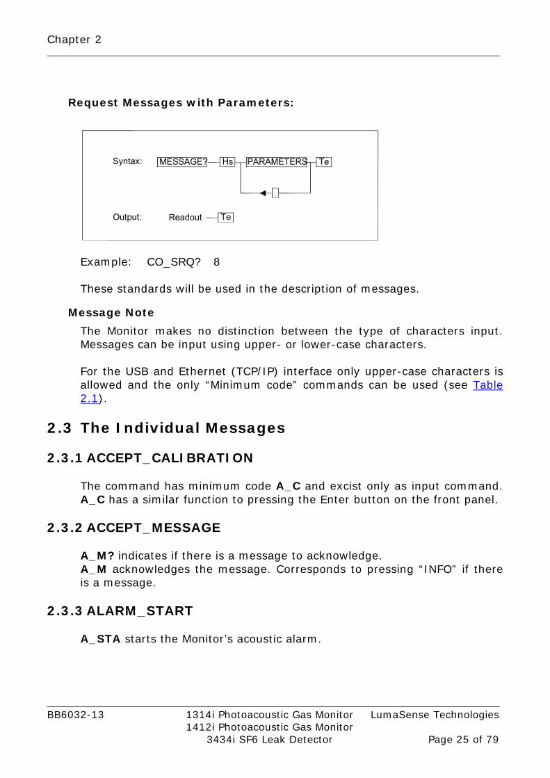
Request Messages with Parameters:
Example: CO_SRQ? 8 These standards will be used in the description of messages.
Message Note The Monitor makes no distinction between the type of characters input. Messages can be input using upper- or lower-case characters. For the USB and Ethernet (TCP/IP) interface only upper-case characters is allowed and the only “Minimum code” commands can be used (see Table 2.1).
2.3 The Individual Messages 2.3.1 ACCEPT_CALIBRATION
The command has minimum code A_C and excist only as input command. A_C has a similar function to pressing the Enter button on the front panel.
2.3.2 ACCEPT_MESSAGE
A_M? indicates if there is a message to acknowledge. A_M acknowledges the message. Corresponds to pressing “INFO” if there is a message.
2.3.3 ALARM_START A_STA starts the Monitor’s acoustic alarm.

Chapter 2 _________________________________________________________________________________________
_________________________________________________________________________________________ BB6032-13 1314i Photoacoustic Gas Monitor LumaSense Technologies 1412i Photoacoustic Gas Monitor 3434i SF6 Leak Detector Page 26 of 79
2.3.4 ALARM_STOP A_STO stops the Monitor’s acoustic alarm.
2.3.5 CONTROL_SRQ CO_SRQ? reads out the event number, NR_1 (0..255), for the events that have been registered in the Event Register specified, NR_1 (1..8). CO_SRQ? can be followed by the character data parameter MEMory. CO_SRQ? NR1 provides a read out acknowledged by the SRQ register, while CO_SRQ? NR1, MEM provides a read out without acknowledging any changes to the register. Examples using CO_SRQ?: If the AVERAGE button has been activated on the Monitor. CO_SRQ? 8 requests the number stored in register 8. Output: 1 This is because the bit number is set as a result of the event “key pressed”. See Table 2.3 to Table 2.7. CO_SRQ sets the specified Event Enable Register. The first number, NR_1 (1..8), is the register number. The second number, NR_1 (0..255), is a bit-mask that tells which occurrence can generate SRQ. For example: CO_SRQ 8,12 The number 12 is written into Register 8 (Special Event Enable Register), setting bits 3 and 4, so that whenever the air pump is started and stopped a Service Request is generated. See Table 2.3 to Table 2.7 for a description of the registers. Note: Register 5, Register 6 and Register 7 are not used.
Register 1 (Data Ready Register) Bit no. Decimal no. Bit name
1 1 Sample Data Ready 2 2 Measurement Task Data Ready 3 4 Calibration Data Ready
4..8 Not used Table 2.3 The contents of Register 1
Register 2 (Reset Activated Register)
Bit no. Decimal no. Bit name 1..8 Not used

Chapter 2 _________________________________________________________________________________________
_________________________________________________________________________________________ BB6032-13 1314i Photoacoustic Gas Monitor LumaSense Technologies 1412i Photoacoustic Gas Monitor 3434i SF6 Leak Detector Page 27 of 79
Table 2.4 The contents of Register 2
Register 3 (Command Completed Register) Bit no. Decimal no. Bit name
1 1 Input/Output Command Finished 2 2 Measurement Task Finished 3 4 Calibration Finished 4 8 Setup Operation Finished 5 16 Memory Operation Finished 6 32 Print Finished
7..8 Not used Table 2.5 The contents of Register 3
Register 4 (Error Register) Bit no. Decimal no. Bit name
1 1 Error in Self-test Detected 2..6 Not used 7 64 HW Error Detected 8 128 SW Error Detected
Table 2.6 The contents of Register 4
Register 8 (Special Event Register)
Bit no. Decimal no. Bit name 1 1 Key Pressed 2 2 Synchronize Required 3 4 Pump Started 4 8 Pump Stopped 5 16 Sample Measurement in Progress 6 32 Bus Control Requested 7 64 SRQ Button Activated 8 128 Self-test Running
Table 2.7 The contents of Register 8 2.3.6 CURRENT_FILTER
C_F? reads out the “filter id”. This indicates which filter (gas) is currently in use. For example: If the Monitor is using the water filter, C_F? will cause
the Monitor to output F_W. C_F determines which filter (gas) is displayed. For example: C_F,F_A causes filter (gas) A to be displayed.

Chapter 2 _________________________________________________________________________________________
_________________________________________________________________________________________ BB6032-13 1314i Photoacoustic Gas Monitor LumaSense Technologies 1412i Photoacoustic Gas Monitor 3434i SF6 Leak Detector Page 28 of 79
2.3.7 CURRENT_SETUP
CU_SE? reads out the number of the active “Measurement Task” on the display. The output from the Monitor will be an integer, NR_1 (1..10). CU_SE defines which “Measurement Task” will be active. For example: CU_SE 5 defines that measurement task 5 is active.
2.3.8 DELETE_MEASUREMENT D_M erases the contents of the defined Memory Location, NR_1 (1..10), from the background memory.
2.3.9 DHCP DHCP? Reads out the Monitors IP address set by the DHCP server i.e. DHCP? Responds: 192.168.000.092
2.3.10 DISPLAY_AVERAGE D_A? indicates the state of the average function. The output from the Monitor can be Yes (average function is active) or No (average function is inactive). D_A followed by a Yes or a No defines the state of the average function.
2.3.11 DISPLAY_STATE D_S? indicates which display buffer is being displayed on the Monitor. The output (display id) from the Monitor is one of the following:
POp_Up Used for error/status/reset messages. REMote The content is chosen via interface. SYstem Default display.
/***** PROTECTED 1 *****/ D_S selects the display buffer to be read out on the display. For example, when: D_S SY is typed, the Monitor will read out “SY” to the controller during normal system, display.

Chapter 2 _________________________________________________________________________________________
_________________________________________________________________________________________ BB6032-13 1314i Photoacoustic Gas Monitor LumaSense Technologies 1412i Photoacoustic Gas Monitor 3434i SF6 Leak Detector Page 29 of 79
2.3.12 EXECUTE_STATE?
EX_S? requests a status of the Monitor. The output from the Monitor can come as one NR_1 or two NR_1s. The first NR_1 gives a general description of the current status of the Monitor. Output no.
(NR_1) Name Description
0 5 6 7 8 9 10 11 12 14 15 16
Display_Run Meas_Clean_Up Meas_Count_Down Meas_Init_Mode Meas_Run Calib_Run Memory_Run Pause_Measurement Print_Menu Print_Run Setup_Run Test_Run
Normal idle state Just after stop measurement Waiting for time to run out Measurement mode selected Measurement running Calibration running Memory mode related Monitor in Pause mode Print selected but not started Print in progress Setup mode selected Test mode
Table 2.8 The meaning of the output from EXecute_State? The second NR_1 is used only if the first NR_1 indicates that the Monitor is calibrating. It describes the calibration procedure. The key to the first integer, NR_1, is shown in Table 2.8. The second integer, given when the Monitor is calibrating, indicates one of the following:
0 No error occurred 1 Warning(s) detected 2 Errors detected
2.3.13 EXTENDED_CONTROL
E_C is used to gain access to a protected message. The Extended_Control message must be send prior to and every time a protected message is sent. For example, the SYNCHRONIZE message is a “protected 59” message. E_C 59 must be send Prior to sending the message. i.e. E_C 59 SY
Chapter 2 _________________________________________________________________________________________
_________________________________________________________________________________________ BB6032-13 1314i Photoacoustic Gas Monitor LumaSense Technologies 1412i Photoacoustic Gas Monitor 3434i SF6 Leak Detector Page 30 of 79
These messages send the synchronization to the Monitor. Note: Protected Messages in this manual are identified with /***** protected 59*****/(see section 2.3.13)
2.3.14 IDENTIFICATION? *IDN? gives the identification of the instrument in the following format:
B&K,1412,ssss,VPxxxx or B&K,1314,ssss,VPxxxx
where:
ssss string of max 10 characters containing the serial number. xxxx software revision number.
If a 1409 Multipoint Sampler is connected to the Gas Monitor, the number of channels will be added to the IDN respond, given the following format for a 1409-12, as an example. B&K,1412,ssss,VPxxxx,12 See appendix ? for further commands to 1409
2.3.15 IDENTIFY? ID? gives the identification of the instrument in this format:
LUMASENSE 1412 or LUMASENSE 1314

Chapter 2 _________________________________________________________________________________________
_________________________________________________________________________________________ BB6032-13 1314i Photoacoustic Gas Monitor LumaSense Technologies 1412i Photoacoustic Gas Monitor 3434i SF6 Leak Detector Page 31 of 79
2.3.16 IDENTIFY? CONFIGURATION
ID? CON gives the identification of the instrument including its configuration. The format is:
LUMASENSE 1314 5 REMOTE ANALOG 12 Where: 1314 is the gas monitor type 5 is the no. of gasses (1, 2 or 5) REMOTE is shown if the front panel is not present ANALOG is shown if the UA1373 Analog interface module is installed 12 is the no. of 1409 channels and is shown if a 1409 is connected A 1314i-1 with an analog output module and a 1409-6 connected will
respond: LUMASENSE 1314 1 ANALOG 6
2.3.17 IP Address
IP_ADDR x,x,x,x set the Monitors IP address (i.e. IP_ADDR 168,168,001,126)
IP_ADDR? Reads out the Monitors IP Address
(i.e. 192.168.001.126)

Chapter 2 _________________________________________________________________________________________
_________________________________________________________________________________________ BB6032-13 1314i Photoacoustic Gas Monitor LumaSense Technologies 1412i Photoacoustic Gas Monitor 3434i SF6 Leak Detector Page 32 of 79
2.3.18 IP Port
IP_PORT x Sets the Monitors IP Port number (i.e. IP_ADDR 23) IP_PORT? Reads out the Monitors IP Port
2.3.19 KEYBOARD_LOCKOUT K_L? indicates whether the front panel push-buttons of the
Monitor are locked. K_L followed by a parameter Y locks or N unlocks the front
panel push-buttons of the Monitor.
2.3.20 MEASURE_AIR_PRESSURE The atmospherical air pressure is measured during reset, measurement, calibration or by the command Measure_Air_Pressure. M_A_P starts an atmospherical air pressure measurement. M_A_P? reads out the atmospherical air pressure.

Chapter 2 _________________________________________________________________________________________
_________________________________________________________________________________________ BB6032-13 1314i Photoacoustic Gas Monitor LumaSense Technologies 1412i Photoacoustic Gas Monitor 3434i SF6 Leak Detector Page 33 of 79
2.3.21 MEASUREMENT_STATE?
M_S? indicates whether the Monitor is measuring. The
Monitor’s output can be Y, it is measuring, or N, it is not measuring.
2.3.22 OUTPUT_CALIBRATION_DATA? O_C_D? provides a readout of calibration data from the Monitor in
ASCII form. When issuing the interface message, the command parameter can be one of the following:
ALl Data for all filters
Filter_A Data for filter A
Filter_B Data for filter B
Filter_C Data for filter C
Filter_D Data for filter D
Filter_E Data for filter E
Filter_W Data for filter W
For example, to get a read out of the calibration data for all the filters, type:
O_C_D? AL

Chapter 2 _________________________________________________________________________________________
_________________________________________________________________________________________ BB6032-13 1314i Photoacoustic Gas Monitor LumaSense Technologies 1412i Photoacoustic Gas Monitor 3434i SF6 Leak Detector Page 34 of 79
2.3.23 OUTPUT_MEASUREMENT?
O_M? provides a readout of measurement data from the Monitor in ASCII form. The O_M? command is followed by none or one of the following character data:
Alphabetical list of interface character data Data fields Minimum
code Output Values
ALARM_LIMIT NUMBER 1 A_L, 1 NR1 ALARM_LIMIT NUMBER 2 A_L, 2 NR1 ALARMLOG AL ”string” ALARMLOG CHANNEL AL,(0-24) ”string” ALARMLOG CHANNEL NUMBER AL,(0-24),n ”string” ALARMLOG FILTER AL,F_(A-W) ”string” ALARMLOG FILTER NUMBER AL,F_(A-W),n ”string” ALARMLOG NUMBERS AL,N NR1 ALARMLOG NUMBERS CHANNEL AL,N,(0-24) NR1 ALARMLOG NUMBERS FILTER AL,N,F_(A-W) NR1 AIR_PRESSURE A_P NR2 BANK1 B NR1 CHAMBER_FLUSH_TIME C_F_T NR1 CHANNEL (0-24) ”string” CONTINUOUS_SAMPLING C_S Y or N CROSS_COMPENSATION C_C Y or N DATE DA “string” EVENT_MARK E_M NR1 FILTER F_(A-W) “string” FIXED_TIME_FLUSH F_T_F Y or N GAS_NAME1 G_N “string” MEMORY MEM NR1 MONITORING_MODE M_M Y or N MONITORING_PERIOD M_P “string” MULTIPLEXER CONTROLLER M_C Y or N NORMALIZATION_TEMPERATURE N_T NR2 SAMPLE_INTERVAL S_I “string” SAMPLE_INTEGRATION_TIME1 S_I_T, NR1 TIME FRAME T_F “string” TUBE_FLUSH_TIME T_F_T NR1 TUBE_LENGTH T_L NR2 USE CHANNEL U_CH Y or N USE_FILTER US_F Y or N USE_MEASURED_AIR_PRESSURE US_M_A_P Y or N WATER_COMPENSATION W_C Y or N
Table 2.9 List of interface character data for use with O_M?

Chapter 2 _________________________________________________________________________________________
_________________________________________________________________________________________ BB6032-13 1314i Photoacoustic Gas Monitor LumaSense Technologies 1412i Photoacoustic Gas Monitor 3434i SF6 Leak Detector Page 35 of 79
When no character data follows, then O_M? reads out measurement data in ASCII form to the screen of the controller.
In some cases, the data character command must be clarified. For example, to obtain the Sample Integration Time for a specific filter (e.g. A) the command must be written as: O_M? S_I_T,F_A returns the sample integration time for filter A. O_M? A_L,F_X,1 returns measurement alarm limit 1 for filter x. O_M? A_L,F_X,2 returns measurement alarm limit 2 for filter x. O_M? US_M_A_P returns measurement printout including air
pressure table. O_M? X,Y,US_M_A_P
returns measurement samples including air pressure from filter number x to y.
O_M? 0,”yyyy-mm-dd”,”hh:mm:ss”,”yyyy-mm-dd”,”hh:mm:ss” Returns the measurements in the display memory
within the specified timeframe. The channel number value at 0 is used when no
multiplexer is connected and the gas monitor is not set the Multiplexer system controller.
The response will be the same as for the O_M? channel job shown below.
The following examples shows the use of O_M? messages when the Gas monitor is set to be the Multiplexer system controller: O_M? M_C Returns Y or N for Multiplexer system controller. O_M? U_CH,1 Returns Y or N for if Channel 1 is used. O_M? U_CH Returns a list of all the channels activation status if
the channel number is not specified. i.e. 1,1,2,1,3,1,4,0,5,0,(etc. up to),24,0
Channel 1, 2 and 3 are in this case activated O_M? T_F,1 Returns the measurement time frame for channel 1 eg. 2016-02-24 08:00:32 2016-04-15 07:47:26

Chapter 2 _________________________________________________________________________________________
_________________________________________________________________________________________ BB6032-13 1314i Photoacoustic Gas Monitor LumaSense Technologies 1412i Photoacoustic Gas Monitor 3434i SF6 Leak Detector Page 36 of 79
O_M? T_F,0 Returns the measurement time frame for all channels.
O_M? 1,”yyyy-mm-dd”,”hh:mm:ss”,”yyyy-mm-dd”,”hh:mm:ss” Returns the measurements from channel 1 in the
display memory within the specified timeframe. The monitor will return all measurements in the
display memory if no timeframe is specified. Eg. 10, 9 2015-12-01,07:46:23,443.15E-03,-,-,-,-,5.9372E+03,0,0,0,0,0,0,0,1,0,0 The format is: Number of samples total,number of samples in each transmission block Date, time, Gas A, Gas B, Gas C, Gas D, Gas E, Gas W,P,O,W,B,F,A,R,V,J,S Gas monitor marks: P Power up flag O Operational error flag W Warning flag Gas marks: B Bad result, Monitor incapable of calculating the Gas Concentration F Filter Alignment error A Alarm limit exceeded Multipoint sampler marks: R Reset done flag V Power failed flag J Job error flag S Software error flag O_M? F_A,”yyyy-mm-dd”,”hh:mm:ss”,”yyyy-mm-dd”,”hh:mm:ss” Returns the measurements from Filter A in the
display memory within the specified timeframe. The monitor will return all measurements in the
display memory if no timeframe is specified. Eg. 18,10
2015-12-01,07:37:06,421.16E-03,-,-,-,-,-,-,-,-,-,-,-,-,-,-,-,-,-,-,-,-,-,-,-,0,0,0,0,0,0,0,0,0,0 2015-12-01,07:37:33,-,417.19E-03,-,-,-,-,-,-,-,-,-,-,-,-,-,-,-,-,-,-,-,-,-,-,0,0,0,0,0,0,0,0,0,0
Chapter 2 _________________________________________________________________________________________
_________________________________________________________________________________________ BB6032-13 1314i Photoacoustic Gas Monitor LumaSense Technologies 1412i Photoacoustic Gas Monitor 3434i SF6 Leak Detector Page 37 of 79
The format is: Number of samples total, number of samples in each transmission block
Date,time,Ch.1,Ch.2,(etc. up to),Ch.24,P,O,W,B,F,A,R,V,J,S The marks are the same as for the O_M? channel job.
O_M? AL,N or O_M? AL,N,0 Returns the total numbers of alarm events for all
channels. O_M? AL,N,1 Returns the total numbers of alarm events for channel 1. O_M? AL,N,F_A Returns the total numbers of alarm events for Filter A. O_M? AL or O_M? AL,0 Returns the total alarm log for all channels. O_M? AL,1 Returns the total alarm log for channel 1. O_M? AL,1,10 Returns the 10 latest alarm events for channel 1. O_M? AL,F_A Returns the total alarm log for Filter A. O_M? AL,F_A,10
Returns the 10 latest alarm events for Filter A.
The format is: date,time,channel,Gas,concentration Eg.
2016-02-26,08:16:23, 9,Gas A,20.305E+03 2016-03-01,14:07:50, 1,Gas A,31.395E+03
2.3.24 OUTPUT_SETUP_DATA?
O_SE_D? reads out setup data from the Monitor in ASCII form. The parameter block, which defines what is readout can be one of the following:
ALl COMmunication CONfiguration
ENvironment
Chapter 2 _________________________________________________________________________________________
_________________________________________________________________________________________ BB6032-13 1314i Photoacoustic Gas Monitor LumaSense Technologies 1412i Photoacoustic Gas Monitor 3434i SF6 Leak Detector Page 38 of 79
FIlters
FOrmat
General
MEAsurement
SYstem
Units
These names refer to the headings in the “setup tree”. All data below these headings will be printed.
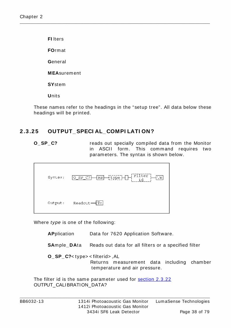
2.3.25 OUTPUT_SPECIAL_COMPILATION?
O_SP_C? reads out specially compiled data from the Monitor
in ASCII form. This command requires two parameters. The syntax is shown below.
Where type is one of the following:
APplication Data for 7620 Application Software.
SAmple_DAta Reads out data for all filters or a specified filter O_SP_C?<type><filterid>,AL
Returns measurement data including chamber temperature and air pressure.
The filter id is the same parameter used for section 2.3.22 OUTPUT_CALIBRATION_DATA?
Chapter 2 _________________________________________________________________________________________
_________________________________________________________________________________________ BB6032-13 1314i Photoacoustic Gas Monitor LumaSense Technologies 1412i Photoacoustic Gas Monitor 3434i SF6 Leak Detector Page 39 of 79
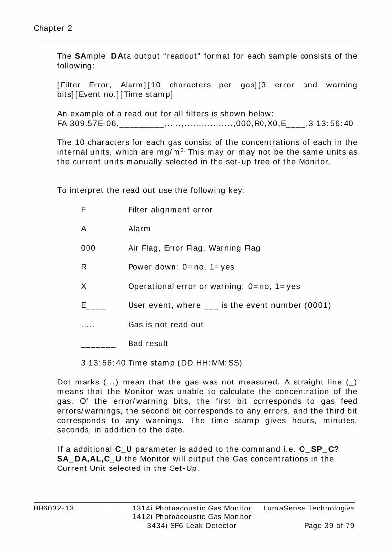
The SAmple_DAta output “readout” format for each sample consists of the following: [Filter Error, Alarm][10 characters per gas][3 error and warning bits][Event no.][Time stamp] An example of a read out for all filters is shown below: FA 309.57E-06,_________,.....,.....,.....,.....,000,R0,X0,E____,3 13:56:40 The 10 characters for each gas consist of the concentrations of each in the internal units, which are mg/m3. This may or may not be the same units as the current units manually selected in the set-up tree of the Monitor.
To interpret the read out use the following key:
F Filter alignment error
A Alarm
000 Air Flag, Error Flag, Warning Flag
R Power down: 0=no, 1=yes
X Operational error or warning: 0=no, 1=yes
E____ User event, where ___ is the event number (0001)
..... Gas is not read out
_______ Bad result
3 13:56:40 Time stamp (DD HH:MM:SS) Dot marks (...) mean that the gas was not measured. A straight line (_) means that the Monitor was unable to calculate the concentration of the gas. Of the error/warning bits, the first bit corresponds to gas feed errors/warnings, the second bit corresponds to any errors, and the third bit corresponds to any warnings. The time stamp gives hours, minutes, seconds, in addition to the date. If a additional C_U parameter is added to the command i.e. O_SP_C? SA_DA,AL,C_U the Monitor will output the Gas concentrations in the Current Unit selected in the Set-Up.

Chapter 2 _________________________________________________________________________________________
_________________________________________________________________________________________ BB6032-13 1314i Photoacoustic Gas Monitor LumaSense Technologies 1412i Photoacoustic Gas Monitor 3434i SF6 Leak Detector Page 40 of 79
If an additional AL parameter is added to the command i.e. O_SP_C? SA_DA,AL,AL, the Monitor will add Chamber temperature and Ambient pressure i.e. 1.0818E+03,.....,.....,.....,....., 7.4709E+03,000,R0,X0,E____,24 15:07:22,305.23,100.89 Where the additional data are: 305.23 Chamber temperature in Kelvin 100.89 Ambient pressure in KPa
2.3.26 PAUSE_MEASUREMENT
PAUSE_M stops measurement or calibration but leaves the chopper running and the IR source heated (Pause mode).
2.3.27 POP_UP_DISPLAY_BUFFER?
P_U_D_B? reads out the contents of the Pop-up display. For example the output string might be: “UNKNOWN HEADER OR CHARACTER DATA”
2.3.28 PROTECTED IP ADDRESS PROTECT x,x,x,x Sets an protected IP address up on the Monitor i.e. PROTECT 192.168.000.046
The Monitor is unprotected if the Address is set to 0.0.0.0
PROTECT? Reads out the protected IP Address
2.3.29 RECALL_MEASUREMENT R_M transfers measurement data from the Memory
Location specified, NR_1 (1..10), in the background memory into the display memory.

Chapter 2 _________________________________________________________________________________________
_________________________________________________________________________________________ BB6032-13 1314i Photoacoustic Gas Monitor LumaSense Technologies 1412i Photoacoustic Gas Monitor 3434i SF6 Leak Detector Page 41 of 79
2.3.30 RELAY
R? indicates the condition of/control over the relays. If
the relay number is included, for example, R? 1, then condition of Relay 1 will be readout. Two outputs are possible:
Yes active No inactive
/***** PROTECTED 59 *****/ (see section 2.3.13 ) The relay(s) condition can be set using R. If the relay number is specified, for example:
R 1,Y Then the relay specified can be set as shown below:
Yes active No passive
If the number is left out:
Yes the relays will be controlled via the interface No the relays will be controlled by the Monitor.
2.3.31 REMOTE_DISPLAY_BUFFER
R_D_B? reads out the contents of Remote display. The
output from the Monitor will be whatever has been written into the buffer via the interface by the user.
R_D_B reads new contents into Remote display buffer. The
data string is 80 characters long and must be enclosed by double quotes(““).
2.3.32 RESET_COMMAND
*RST partially resets the Monitor. For details about resetting the Monitor, see the Instruction Manual.
Chapter 2 _________________________________________________________________________________________
_________________________________________________________________________________________ BB6032-13 1314i Photoacoustic Gas Monitor LumaSense Technologies 1412i Photoacoustic Gas Monitor 3434i SF6 Leak Detector Page 42 of 79
2.3.33 RESET_STATUS_BYTE R_S_B clears the Status byte, i.e. it is set to 00000000
2.3.34 RESET_SYSTEM Warning! during a full reset of the Monitor, all data in the Display Memory and Background Memory will be lost. RESET_SY is followed by a parameter, which should be one of the following:
PARTial The Monitor is partially reset. FULl The Monitor is fully reset.
If the parameter is omitted, the Monitor is partially reset. /***** PROTECTED 71 *****/ Warning! during a factory reset of the Monitor, all data in the Source Memory will be lost.
FActory The Monitor makes a total E2PROM reset. See the Instruction Manual for information on resetting the Monitor.

Chapter 2 _________________________________________________________________________________________
_________________________________________________________________________________________ BB6032-13 1314i Photoacoustic Gas Monitor LumaSense Technologies 1412i Photoacoustic Gas Monitor 3434i SF6 Leak Detector Page 43 of 79
2.3.35 SELF_TEST?
*TST causes the Monitor to carry out a self-test. The self-test can
only be carried out when the Monitor is in idle mode. *TST? Causes the Monitor to output the result of the self-test (NR_1). The output has one of these values:
-4 The self-test is not performed -3 The self-test is in progress –2 The Monitor is not in idle mode (display mode). Therefore the
test can’t be carried out. –1 Operational Error Flags have been set after the test. 0 No flag has been set after the test. 1 Warning Flags have been set after the test.
For more details about self tests and Warning and Error messages, refer to the Instruction Manual.
2.3.36 SERVICE_REQUEST_ENABLE The Service Request Enable Register is a mask for the Status Byte (see 2.3.42) i.e. a bit that is set in the Status Byte will only cause a Service Request if the corresponding bit in the Service Request Enable Register is also set. This register is, therefore, used by the controller to enable and disable Service Requests. S_R_E? will read out the decimal value of the SRQ enable register. The output (NR_1) is in the range 0..255. For example, if the register contained the binary number 0000 1000 and you typed:
S_R_E? The Monitor would read out the decimal number 8, indicating that bit 4 is set and that an error has occurred. S_R_E sets the Service Request Enable Register. The number in the register lies in the range 0..255. For example, if you typed:
S_R_E 8

Chapter 2 _________________________________________________________________________________________
_________________________________________________________________________________________ BB6032-13 1314i Photoacoustic Gas Monitor LumaSense Technologies 1412i Photoacoustic Gas Monitor 3434i SF6 Leak Detector Page 44 of 79
The Monitor would set bit 4 of the register to binary 1, so that whenever bit 4 of the Status Byte is set (the Error bit) an SRQ is generated. The contents of the Service Request Enable Register is given in Table 2.11.
Service Request Enable Register Bit no. Bit value Bit name
1 2 3 4 5 6 7 8
1 2 4 8 16 32 64 128
Data Ready Reset Activated Command Completed Error (Not user definable) Abnormal (Not user definable) Special event
Table 2.11 The contents of the Service Request Enable Register
Chapter 2 _________________________________________________________________________________________
_________________________________________________________________________________________ BB6032-13 1314i Photoacoustic Gas Monitor LumaSense Technologies 1412i Photoacoustic Gas Monitor 3434i SF6 Leak Detector Page 45 of 79
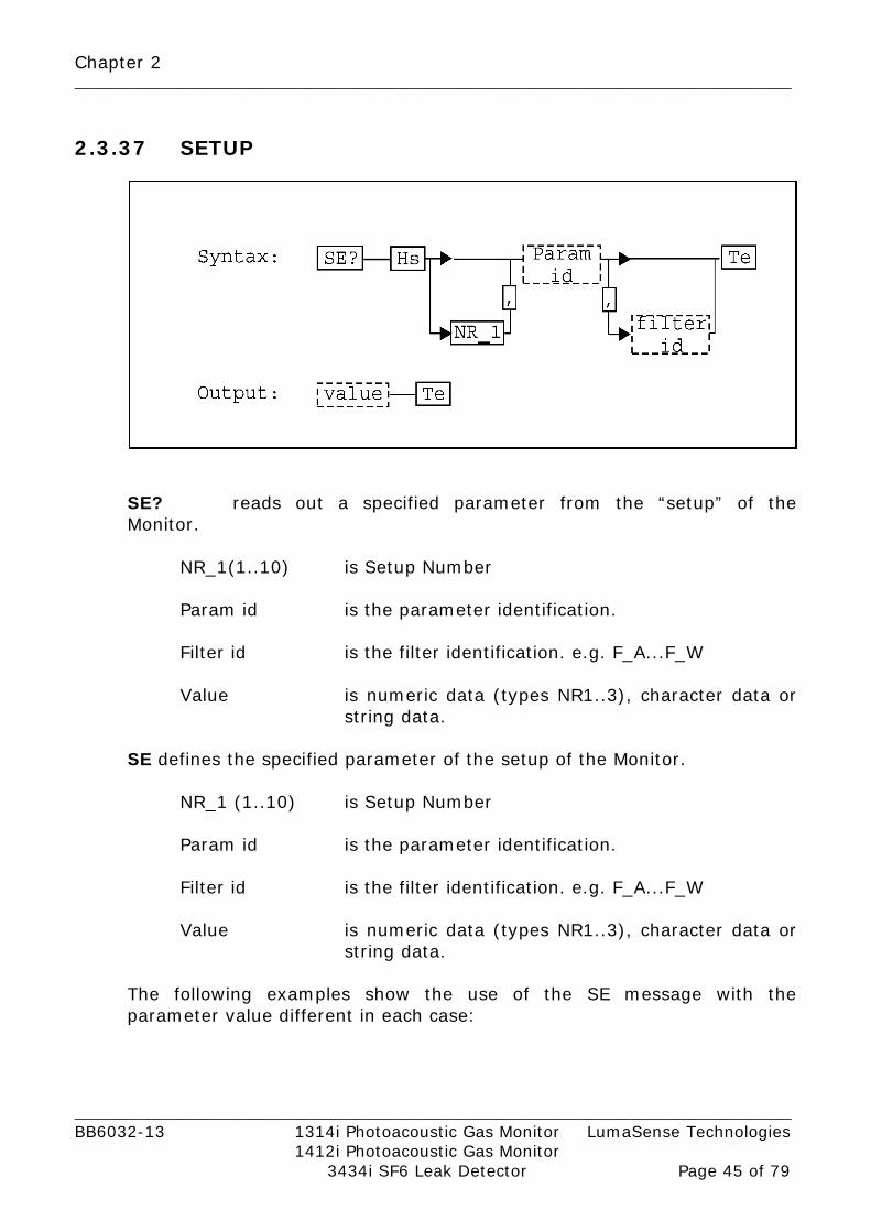
2.3.37 SETUP
SE? reads out a specified parameter from the “setup” of the Monitor.
NR_1(1..10) is Setup Number
Param id is the parameter identification.
Filter id is the filter identification. e.g. F_A...F_W
Value is numeric data (types NR1..3), character data or string data.
SE defines the specified parameter of the setup of the Monitor.
NR_1 (1..10) is Setup Number Param id is the parameter identification. Filter id is the filter identification. e.g. F_A...F_W Value is numeric data (types NR1..3), character data or
string data. The following examples show the use of the SE message with the parameter value different in each case:

Chapter 2 _________________________________________________________________________________________
_________________________________________________________________________________________ BB6032-13 1314i Photoacoustic Gas Monitor LumaSense Technologies 1412i Photoacoustic Gas Monitor 3434i SF6 Leak Detector Page 46 of 79
SE T_L,10.5 in this case value is numeric and the length of the sampling tube is set to 10.5 in the current length units.
SE S_H,X_O in this case value is character data.
SE G_N,F_A,“carbon dioxide”
in this case value is a text string and the gas name for filter A is set to carbon dioxide
SE 2,M_P,“2 12:00”
in this case value is a time string. Monitoring task No. 2 is set up for a period of 2 days and 12 hours.
SE F_T_F,Y in this case, the Fixed Time Flushing is activated.
The times for the chamber and the tube need to be set. Acceptable values for these parameters are given in the Instruction Manual. To set the times to 10s for the chamber and 20s for the tube, send:
SE C_F_T,10 and SE T_F_T,20. SE? C_W_S returns Y og N to Continuous_Warm_System. SE C_W_S,Y (or N) takes character data Y or N as parameter. Y states that the measurement system is heated
in idle mode. Heated means that the infrared source is heated, the chopper is running and the filters are positioned in a cyclic sequence. The heating is started after reset, finished measurement and finished calibration.
N states that the measurement system is only kept warm during measurement and calibration.
Changes in heating mode are updated after reset, finished measurement and finished calibration.
Default after EEPROM reset is N. SE? US_M_A_P returns Y or N to Use_Measured_Air_Pressure. SE US_M_A_P,Y (or N) takes character data Y or N as parameter. Y states that the measured atmospherical
pressure is used for calculations. N states that the entered actual air pressure in
setup is used for calculations.

Chapter 2 _________________________________________________________________________________________
_________________________________________________________________________________________ BB6032-13 1314i Photoacoustic Gas Monitor LumaSense Technologies 1412i Photoacoustic Gas Monitor 3434i SF6 Leak Detector Page 47 of 79
SE? USER_L returns 1,2 or 3 for the User_Level. SE USER_L takes NR1 data 1,2 or 3. The number is the user level associated with the
lock function. Default after EEPROM reset is 3. SE? PASSWORD returns a string of length 0 to 5. SE PASSWORD takes a string of length 0 to 5. The string is the password associated with the lock
function. When comparing the password string with the password entered from the front panel (always 5 characters) the string is considered to be right padded with spaces.
Default after EEPROM reset is “*****”. SE A_L, F_x,y, 1 sets setup alarm limit 1 for filter x to y. SE A_L, F_x,y, 2 sets setup alarm limit 2 for filter x to y. SE? A_L, F_x, 1 returns setup alarm limit 1 for filter x. SE? A_L, F_x, 2 returns setup alarm limit 2 for filter x. SE? MEM returns Y or N. SE MEM takes character data Y or N as parameter. Y states that measurement history is stored, i.e.
all available memory is used for storing measurement results.
N states that only the results of the latest gas sample are stored. This enables a faster start up of the analyser.
Default after EEPROM reset is Y.
SE? PR,A_P returns Y or N. SE PR,A_P takes character data Y or N as parameter. Y states that an air pressure table is printed when
the measured concentrations are printed. N states that no air pressure table is printed when
the measured concentrations are printed. Default after EEPROM reset is N. SE DHCP,Y (or N) Y sets the Monitors IP Address to be set by the
DHCP server. N sets the Monitors IP address to be locally.

Chapter 2 _________________________________________________________________________________________
_________________________________________________________________________________________ BB6032-13 1314i Photoacoustic Gas Monitor LumaSense Technologies 1412i Photoacoustic Gas Monitor 3434i SF6 Leak Detector Page 48 of 79
The following examples show the use of the SE message for multiplexer control:
SE M_C,Y Y sets the Monitors to be multiplexer system controller.
N sets the Monitor not to be system controller. SE U_CH,1,Y Activate Multiplexer channel 1. N Deactivates Multiplexer channel 1.
SE? U_CH,1 returns Y or N for use of the defined channel. SE? U_CH returns a list of activated channels.
i.e. 1,1,2,1,3,1,4,0,5,0,(etc. up to),24,0 Channel 1, 2 and 3 are in this case activated.
The following examples show the use of the SE message for Analog output and Relay output setup: SE A_U,U_4_20MA_PPM Setup the Analog unit to 4-20 mA / ppm SE? A_U Returns the Analog unit SE A_MI_C,F_A,100.0
Setup the Analog minimum concentration for Filter A to the value 100
SE A_MA_C,F_A,1.0E3
Setup the Analog maximum concentration for Filter A to the value 1000
SE A_MA_C,F_A,1E32
Resets the Analog maximum concentration for Filter A
SE A_R_C_M,Y Activates the Analog relay channel mode
SE A_R_N,1,2 Setup Alarm limit exceeded on Multiplexer channel 1 to activate Relay 2 on the Analog & Relay output module.
SE A_R_N,1,__ (or 65535)
Setup Alarm limit exceeded on Multiplexer channel 1 to not activate any Relays on the Analog & Relay output module.

Chapter 2 _________________________________________________________________________________________
_________________________________________________________________________________________ BB6032-13 1314i Photoacoustic Gas Monitor LumaSense Technologies 1412i Photoacoustic Gas Monitor 3434i SF6 Leak Detector Page 49 of 79
SE? A_R_N,1 Returns the Relay linked to Channel 1 SE? A_R_N Return a list of all channels and the linked relays. Ie.
1,2,2,1,3,0,4,2,(etc. up to),24,0 In this example Ch.1 is linked to Relay 2 Ch. 2 is linked to Relay 1 Ch. 3 is not linked to any Relays Ch. 4 is linked to 2 Ch. 24 is not linked to any Relays
SE A_C_A,A1 Setup the alarm level on channel 1 to be high
alarm limit 1. SE? A_C_A,1 Returns the alarm level for channel 1 SE? A_C_A Setup the alarm level on channel 1 to be high
alarm limit. i.e. 1,1,2,1,3,2,4,2,(etc. up to),24,1 In this example
Ch. 1, 2 and 24 are set to alarm limit 1 Ch. 3 and 4 are set to alarm limit 2 All allowable parameter ids and values for Setup are given in Table 2.12 and Table 2.13.
Setup parameter id Minimum code ALARM_LIMIT A_L AIR_PRESSURE A_P ANALOG CHANNEL ALARM A_C_A ANALOG MINIMUM CONCENTRATION A_MI_C ANALOG MAXIMUM CONCENTRATION A_MA_C ANALOG RELAY CHANNEL MODE A_R_C_M ANALOG RELAY NUMBER A_R_N ANALOG UNIT A_U AVERAGE_TIME A_T BANK (Filter) B BAUD_RATE B_R CHAMBER_FLUSH_TIME C_F_T CLOCK CL CROSS_COMPENSATION C_C CONTINUOUS_SAMPLING C_S CONTINUOUS_WARM_SYSTEM C_W_S CONCENTRATION_UNIT C_U DATE DA

Chapter 2 _________________________________________________________________________________________
_________________________________________________________________________________________ BB6032-13 1314i Photoacoustic Gas Monitor LumaSense Technologies 1412i Photoacoustic Gas Monitor 3434i SF6 Leak Detector Page 50 of 79
DATA_BIT D_B DATA_LOG D_L DHCP DHCP ERROR_LOGGING E_L FIXED_TIME_FLUSH F_T_F GAS_NAME G_N GAS_WEIGHT G_W HARD_WIRE H_W HUMIDITY_UNIT H_U LENGTH_UNIT L_U MEMORY MEM MONITORING_MODE (preset period) M_M MONITORING_PERIOD M_P MULTIPLEXER CONTROLLER M_C NORMALIZATION_TEMPERATURE N_T PARITY PARI PASSWORD PASSWORD PRESSURE_UNIT PR_U PRINT,AIR_PRESSURE PR,A_P PRINT_ALL P_P_A PRINT_FILTER P_P_F PRINTER_LINK PR_L POWER_UP_TEST (+ regular self-test) P_U_T SAMPLE_INTERVAL S_I SAMPLE_INTEGRATION_TIME S_I_T SOFT_HANDSHAKE (Handshake mode) S_H SOUND_VOLUME S_V STOP_BIT S_B TEMPERATURE_UNIT T_U TUBE_FLUSH_TIME T_F_T TUBE_LENGTH T_L UA_NUMBER UA_N USE CHANNEL U_CH USE_FILTER US_F USE_MEASURED_AIR_PRESSURE US_M_A_P USER_LEVEL USER_L WATER_COMPENSATION W_C
Table 2.12 The setup parameter ids

Chapter 2 _________________________________________________________________________________________
_________________________________________________________________________________________ BB6032-13 1314i Photoacoustic Gas Monitor LumaSense Technologies 1412i Photoacoustic Gas Monitor 3434i SF6 Leak Detector Page 51 of 79
Setup parameter value Minimum code ALARM LIMIT 1 A1 ALARM LIMIT 2 A2 EVEN EV ETHERNET ETH HARD_WIRE H_W LEASED_LINE L_L NO (none) N ODD O RS_232 RS SWITCHED_LINE S_L THREE_WIRE T_W UNIT_C U_CE UNIT_F U_FA UNIT_ft U_FEET UNIT_K U_KE UNIT_kPa U_KPA UNIT_mbar U_MBAR UNIT_m U_METER UNIT_mg/m3 U_MG_M UNIT_mmHg U_MM_HG UNIT_ppm U_PPM UNIT_Tdew U_TDEW USB USB X-ON/X-OFF X_O YES Y UNIT 0-20 Ma / mg/m3 U_0_20MA_MG_M3 UNIT 4-20 Ma / mg/m3 U_4_20MA_MG_M3 UNIT 0-10 V / mg/m3 U_V_MG_M3 UNIT 0-20 Ma / ppm U_0_20MA_PPM UNIT 4-20 Ma / ppm U_4_20MA_PPM UNIT 0-10 V / ppm U_V_PPM FILTER A F_A FILTER B F_B FILTER C F_C FILTER D F_D FILTER E F_E FILTER W F_W NONE __ or 65535
Table 2.13 Setup parameter values 2.3.38 SOFTWARE_IDENTIFICATION?
S_I? reads out the software identification string, for example the
output might be “SOFTWARE ID VPxxxx 05-10-21 08.10”.

Chapter 2 _________________________________________________________________________________________
_________________________________________________________________________________________ BB6032-13 1314i Photoacoustic Gas Monitor LumaSense Technologies 1412i Photoacoustic Gas Monitor 3434i SF6 Leak Detector Page 52 of 79
2.3.39 START_CALIBRATION The command has minimum code STA_C and exists only as input command.
STA_C, calibration type, calibration parameters starts a calibration of the specified calibration type. The calibration parameters depend on the calibration type.
Calibration type Minimum code Calibration parameters Calibration_Zero C_Z Filter ABCDE, filter W Calibration_Hum C_H Filter ABCDE, filter W Calibration_Zero_Hum C_Z_H Filter ABCDE, filter W Calibration_Gas_Span C_G_S Filter, two point, low conc, high
conc, cross Calibration_Water_Span C_W_S Conc
Calibration Parameter Value
Filter ABCDE YES or NO to all installed filters from A to E Filter W YES or NO to filter W Filter One of FILTER A to FILTER W Two point YES or NO to two point calibration Low conc. Two point low concentration High conc. Two point high concentration or single point
concentration Cross YES or NO to cross calibration Conc. Span concentration
Examples: STArt_Calibration Calibration_Zero,Yes,No Calibration of Filter A to E. Filter W not calibrated. STArt_Calibration Calibration_Zero,Yes,Yes Calibration of Filter A to W. STArt_Calibration Calibration_Zero,No,Yes Calibration of Filter W without calibration of Filter A to E is not valid. STArt_Calibration Calibration_Zero_Hum,Yes,No
Combined zero- and humidity calibration of Filter A-E. Filter W not zero calibrated.
STArt_Calibration Calibration_Zero_Hum,Yes,Yes
Combined zero- and humidity calibration of Filter A-E. Filter W is zero calibrated. (First time calibration of instrument!).

Chapter 2 _________________________________________________________________________________________
_________________________________________________________________________________________ BB6032-13 1314i Photoacoustic Gas Monitor LumaSense Technologies 1412i Photoacoustic Gas Monitor 3434i SF6 Leak Detector Page 53 of 79
STArt_Calibration Calibration_Gas_Span, Filter_A,No,0.0,345.34,Yes
Single Point calibration of filter A with 345.34 ppm gas and with cross calibration.
STArt_Calibration Calibration_Water_Span,18000 Calibration of water filter with 18000mg/m3 water. 2.3.40 START_DELAYED_MEASUREMENT
S_D_M “d hh:mm” or S_D_M “dd hh:mm” starts a Monitoring task at the specified time. D ~ day, h ~ hour, m ~ minute.
2.3.41 START_MEASUREMENT
STA_M starts a monitoring task immediately.
2.3.42 STATUS_BYTE? *STB? reads out the contents of the Status-Byte, see Fig. 7.1.The number (NR_1) is in the range 0..255. For example, if the Status Byte contained the binary number 00000001 and you typed *STB? , the Monitor would return the decimal number 1, indicating that the Data Ready bit was set. The contents of the Status Byte is shown in Table 2.14.
Bit no. Bit name 1 2 3 4 5 6 7 8
Data ready Reset activated Command completed Error Busy Abnormal SRQ_line Special event
Table 2.14 Contents of Status Byte

Chapter 2 _________________________________________________________________________________________
_________________________________________________________________________________________ BB6032-13 1314i Photoacoustic Gas Monitor LumaSense Technologies 1412i Photoacoustic Gas Monitor 3434i SF6 Leak Detector Page 54 of 79
2.3.43 STOP_MEASUREMENT
STOP_M stops the current measurement task.
2.3.44 STORE_DEFAULT
STOR_D stores the current setup in non volatile memory. A full reset will recall the saved setup as the current setup. Exists only as input command.
2.3.45 STORE_MEASUREMENT
STOR_M stores the contents of the display memory in the background memory at a specified (NR_1) (1..10) location.
2.3.46 SYNCHRONIZE
SY? Reads out the pump synchronization condition. This message is for use when an external pump (ex. A pump in the 1409) is connected to the Monitor. There are two possible outputs:
Yes indicates that the Monitor pump will start only when a synchronization command is received from the controller. This is the required condition when an external pump is connected to the Monitor. If the synchronization condition is not set to Yes, and an external pump is connected, then airway errors can occur.
No indicates that the Monitor pump is controlled by the
Monitor. /***** PROTECTED 59 *****/ (see section 2.3.13) SY sets the pump synchronization condition:
Yes the Monitor pump will start only when a synchronization command is received from the controller.
No the pump will be controlled by the Monitor.

Chapter 2 _________________________________________________________________________________________
_________________________________________________________________________________________ BB6032-13 1314i Photoacoustic Gas Monitor LumaSense Technologies 1412i Photoacoustic Gas Monitor 3434i SF6 Leak Detector Page 55 of 79
If a Yes or No parameter is not given, then the Monitor pump starts if the Monitor is waiting for the Synchronize command.
2.3.47 SYNCHRONIZED_MODE_CONTINUOUS_PUMP SY_CON set-up the Monitor in Continuous pump synchronization mode. In Continuous pump synchronization Mode the predefined Tube- and Chamber-flush times are disabled. Tube-flush is performed while Gas-measurements are performed on all optical filters (a complete Gas-Measurement cycle). Chamber-flush start as soon as a complete Gas-Measurement cycle is performed. The Chamber-flush continues until a synchronization message is received, then the Chamber-flush stops and the Gas-measurement cycle is repeated. It the Monitor is set-up to measure the ambient air pressure the pump stops for a few seconds in each Measurement cycle to enable the Monitor to measure the ambient air pressure.
Following commands are used: SY? CON Reads out the continuous pump synchronization
mode. Possible outputs are: Yes The Gas-Monitor is set in continuous pump
synchronization mode. No Indicates that the Monitor pump sequence is
controlled by the monitor. SY? 1 Reads out if synchronization is required. Possible outputs are: Yes The Gas-Monitor waits for synchronization to
continue Gas measurement. Chamber-flush is activated.
No Synchronization is not required. SY 1 Synchronize the Gas-Monitor. /*****PROTECTED 59*****/ (see section 2.3.13)

Chapter 2 _________________________________________________________________________________________
_________________________________________________________________________________________ BB6032-13 1314i Photoacoustic Gas Monitor LumaSense Technologies 1412i Photoacoustic Gas Monitor 3434i SF6 Leak Detector Page 56 of 79
SY CON Sets the continuous pump synchronization mode Yes Activates the continuous pump synchronization
mode No Deactivates the continuous pump synchronization
mode.
2.3.48 SYSTEM_DISPLAY_BUFFER? SY_D_B? reads out the contents of the Monitor default display. For example, the output might be:
SELECT SETUP BRANCH MEASUREMENT FORMAT CONFIGURATION 2.3.49 TIME_SINCE_RESET?
T_S_R? reads out the number of seconds since the last reset/power-up of the Monitor. The output (NR1) is in the range 0..4294967295 (about 136 years).
2.3.50 UNPROTECT UNPROTECT Sets the Monitors protected IP Address to 0.0.0.0
meaning that it is unprotected

Chapter 2 _________________________________________________________________________________________
_________________________________________________________________________________________ BB6032-13 1314i Photoacoustic Gas Monitor LumaSense Technologies 1412i Photoacoustic Gas Monitor 3434i SF6 Leak Detector Page 57 of 79
2.3.51 ZDLOG
The ZDLOG is used to log events in the firmware like i.e. software errors that causes the system to reboot. The type and numbers of events is defined with Mask with the following definitions:
Byte Decimal Event Mask 0 1 EVMASK_INITIALIZE 1 2 EVMASK_MEASURE 2 4 EVMASK_CALIBRATE 3 8 EVMASK_MEASERROR 4 16 EVMASK_MEASWARNING 5 32 EVMASK_MEASCONTROL 6 64 Not used 7 128 EVMASK_ADDDEVICE 8 256 EVMASK_SOFTERROR 9 512 EVMASK_MEMORY 10 1024 EVMASK_CANBUS 11 2048 EVMASK_RS232 12 4096 EVMASK_ETHERNET 13 8192 EVMASK_USB 14 16384 EVMASK_KEYENTRIES
Default Mask is 792 meaning that Memory, Softerrors, Measurement warnings and Measurement errors are logged. ZDLOG? Reads out the Mask /*****PROTECTED 1*****/ (see section 2.3.13) ZDLOG <mask> selects the Mask.
e.g. E_C 1;ZDLOG 792 ZDLOG ERASE erases the log. ZDLOG? <mask>,x reads out the last x numbers of occurrences in the
log with the defined mask. e.g. E_C 1;ZDLOG? 792,10 reads out the last 10 occurrences of mask 792 and could give the following output: 2014-06-10 14:01:59.4965 SOFTERR ZD0810 SOFT ERROR AT uticht.c 1534 Ex_Store_Meas Unknown Mem_Result

Chapter 3 _________________________________________________________________________________________
_________________________________________________________________________________________ BB6032-13 1314i Photoacoustic Gas Monitor LumaSense Technologies 1412i Photoacoustic Gas Monitor 3434i SF6 Leak Detector Page 58 of 79
Chapter 3
Interface Character Data
April 2017

Chapter 3 _________________________________________________________________________________________
_________________________________________________________________________________________ BB6032-13 1314i Photoacoustic Gas Monitor LumaSense Technologies 1412i Photoacoustic Gas Monitor 3434i SF6 Leak Detector Page 59 of 79
3.1 List of Interface Character Data
Alphabetical list of interface character data Data fields Minimum code
ALL AL APPLICATION AP ALARM_LIMIT A_L AVERAGE AV ALARM LIMIT 1 A1 ALARM LIMIT 2 A2 ALARM_LIMIT_NUMBER1 A_L_1 ALARM_LIMIT_NUMBER2 A_L_2 ALARMLOG AL ALARMLOG CHANNEL AL,(0-24) ALARMLOG CHANNEL NUMBER AL,(0-24),n ALARMLOG FILTER AL,F_(A-W) ALARMLOG FILTER NUMBER AL,F_(A-W),n ALARMLOG NUMBERS AL,N ALARMLOG NUMBERS CHANNEL AL,N,(0-24) ALARMLOG NUMBERS FILTER AL,N,F_(A-W) AIR_PRESSURE A_P ANALOG CHANNEL ALARM A_C_A ANALOG MINIMUM CONCENTRATION A_MI_C ANALOG MAXIMUM CONCENTRATION A_MA_C ANALOG RELAY CHANNEL MODE A_R_C_M ANALOG RELAY NUMBER A_R_N ANALOG UNIT A_U AVERAGE_TIME A_T BANK B BAUD_RATE B_R CALIBRATION_DATA C_D CHAMBER_FLUSH_TIME C_F_T CLOCK CL COMMUNICATION COM CONFIGURATION CON CONTINUOUS_SAMPLING C_S CONTINUOUS_WARM_SYSTEM C_W_S CONCENTRATION_UNIT C_U CROSS_COMPENSATION C_C CURRENT_FILTER C_F DATA_BIT D_B DATA_LOG D_L DATE DA DOWN_DIRECTION DO_D ENTER_EXECUTE E_E ENVIRONMENT EN

Chapter 3 _________________________________________________________________________________________
_________________________________________________________________________________________ BB6032-13 1314i Photoacoustic Gas Monitor LumaSense Technologies 1412i Photoacoustic Gas Monitor 3434i SF6 Leak Detector Page 60 of 79
ERROR_LOGGING E_L ERROR_VALUES E_V EVEN EV EVENT_MARK E_M EXCLUSIVE EX FACTORY FA FILTERS FI FILTER_A F_A FILTER_B F_B FILTER_C F_C FILTER_D F_D FILTER_E F_E FILTER_W F_W FIXED_TIME_FLUSH F_T_F FORMAT FO FULL FUL GAS_NAME G_N GAS_VALUES G_V GAS_WEIGHT G_W GENERAL G HARD_WIRE H_W HUMIDITY_UNIT H_U IDENTITY ID? IDENTITY CONFIGURATION ID? CON INCLUSIVE IN INFO STATU LEASED_LINE L_L LEFT_DIRECTION LE_D LENGTH_UNIT L_U LINEAR LIN MEASUREMENT MEA MEASUREMENT_DONE M_D MEMORY MEM MONITORING_MODE M_M MONITORING_PERIOD M_P MULTIPLEXER CONTROLLER M_C NO (NONE) N NORMALIZATION_TEMPERATURE N_T ODD O PASSWORD PASSWORD PARITY PARI PARTIAL PART POP_UP PO_U POWER_UP_TEST P_U_T PRESSURE_UNIT P_U
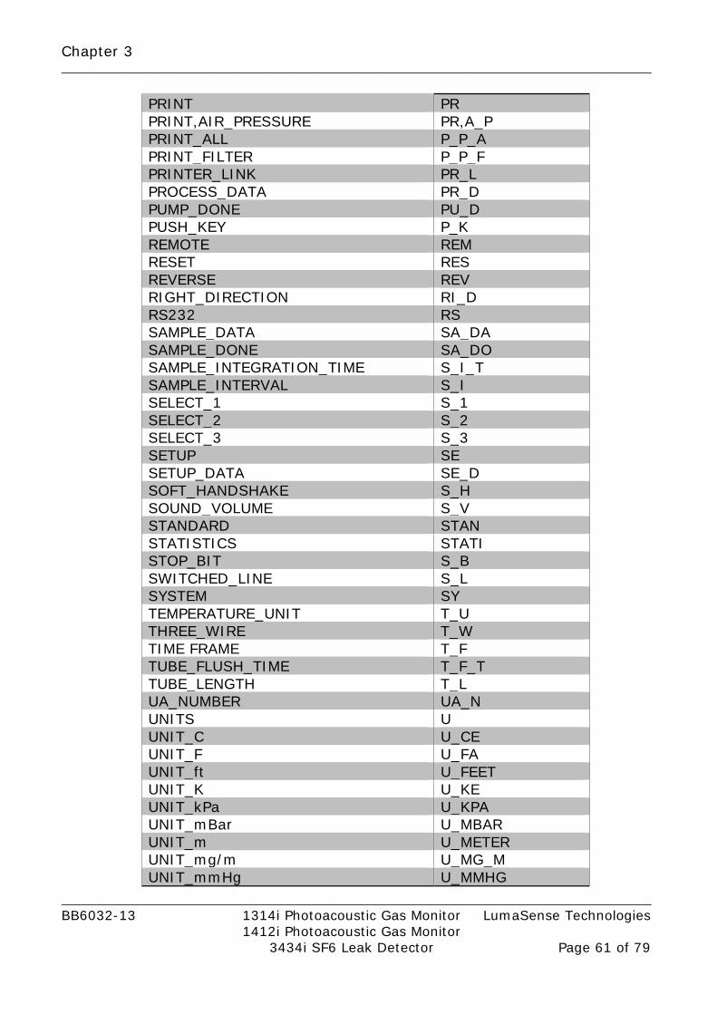
Chapter 3 _________________________________________________________________________________________
_________________________________________________________________________________________ BB6032-13 1314i Photoacoustic Gas Monitor LumaSense Technologies 1412i Photoacoustic Gas Monitor 3434i SF6 Leak Detector Page 61 of 79
PRINT PR PRINT,AIR_PRESSURE PR,A_P PRINT_ALL P_P_A PRINT_FILTER P_P_F PRINTER_LINK PR_L PROCESS_DATA PR_D PUMP_DONE PU_D PUSH_KEY P_K REMOTE REM RESET RES REVERSE REV RIGHT_DIRECTION RI_D RS232 RS SAMPLE_DATA SA_DA SAMPLE_DONE SA_DO SAMPLE_INTEGRATION_TIME S_I_T SAMPLE_INTERVAL S_I SELECT_1 S_1 SELECT_2 S_2 SELECT_3 S_3 SETUP SE SETUP_DATA SE_D SOFT_HANDSHAKE S_H SOUND_VOLUME S_V STANDARD STAN STATISTICS STATI STOP_BIT S_B SWITCHED_LINE S_L SYSTEM SY TEMPERATURE_UNIT T_U THREE_WIRE T_W TIME FRAME T_F TUBE_FLUSH_TIME T_F_T TUBE_LENGTH T_L UA_NUMBER UA_N UNITS U UNIT_C U_CE UNIT_F U_FA UNIT_ft U_FEET UNIT_K U_KE UNIT_kPa U_KPA UNIT_mBar U_MBAR UNIT_m U_METER UNIT_mg/m U_MG_M UNIT_mmHg U_MMHG

Chapter 3 _________________________________________________________________________________________
_________________________________________________________________________________________ BB6032-13 1314i Photoacoustic Gas Monitor LumaSense Technologies 1412i Photoacoustic Gas Monitor 3434i SF6 Leak Detector Page 62 of 79
UNIT_ppm U_PPM UNIT_Tdew U_TDEW UNIT 0-20 mA / mg/m3 U_0_20MA_MG_M3 UNIT 4-20 mA / mg/m3 U_4_20MA_MG_M3 UNIT 0-10 V / mg/m3 U_V_MG_M3 UNIT 0-20 mA / ppm U_0_20MA_PPM UNIT 4-20 mA / ppm U_4_20MA_PPM UNIT 0-10 V / ppm U_V_PPM USE CHANNEL U_CH WARNING_VALUES W_V WATER_COMPENSATION W_C X-ON/X-OFF X_O YES Y
Table 3.1 List of interface character data

Chapter 4 _________________________________________________________________________________________
_________________________________________________________________________________________ BB6032-13 1314i Photoacoustic Gas Monitor LumaSense Technologies 1412i Photoacoustic Gas Monitor 3434i SF6 Leak Detector Page 63 of 79
Chapter 4
Error Messages
April 2017

Chapter 4 _________________________________________________________________________________________
_________________________________________________________________________________________ BB6032-13 1314i Photoacoustic Gas Monitor LumaSense Technologies 1412i Photoacoustic Gas Monitor 3434i SF6 Leak Detector Page 64 of 79
4.1 List of Error Messages.
Error Message Description AD BLOCK SPECIFICATION SYNTAX
Syntax error. Illegal specification of the block data. The correct syntax is #nc...c, where n is the length count and c is the digit. The size of the block may be wrong.
BAD CHARACTER DATA SYNTAX Syntax error. Illegal character found in the character data types.
BAD HEADER DATA SYNTAX Syntax error. Illegal character found in the message header.
BAD STRING DATA SYNTAX Syntax error. The text string is not surrounded by quotes (“)
BAD TERMINATOR Syntax error. Illegal message terminator, (not <LF>).
BAD TIME STRING SYNTAX Syntax error. The text string to indicate date/time is not correct.
BLOCK DATA EXPECTED Syntax error. Illegal data type received. BLOCK DATA NOT COMPLETED Syntax error. Block data ended/interrupted
before the usual termination. BLOCK DATA OVERRUN Syntax error. Block data has not been
ended according to the block specification. BLOCK DATA. PARAMETER OUT OF RANGE
The data in the block is illegal
CHARACTER DATA EXPECTED Syntax error. The wrong data type was received.
HANDSHAKE ERROR Occurs in connection with the RS–232 ILLEGAL CHARACTER Illegal syntax. The error can appear in
many contexts. ILLEGAL CHARACTER DATA The character data is not correct in this
context. ILLEGAL STATE FOR OPERATION
The Monitor is currently in an operating state where the message is illegal.
ILLEGAL STRING DATA The contents of the string is not correct. INTERNAL BUFFER OVERFLOW Syntax error. The header/Character data is
too big. The text string is too long etc. JOB IS CANCELLED The current output-message is interrupted
by a new input-message. JOB NOT ALLOWED FOR INPUT OR OUTPUT
Syntax error. The user has changed an input-only message into an output message b use of a “?”, or an output-only message into an input message.
MISSING CHARACTER E.g. a “+” and <LF> are received. The “+” indicates that a numerical value (NRx) is to follow, but this numerical value does not

Chapter 4 _________________________________________________________________________________________
_________________________________________________________________________________________ BB6032-13 1314i Photoacoustic Gas Monitor LumaSense Technologies 1412i Photoacoustic Gas Monitor 3434i SF6 Leak Detector Page 65 of 79
Error Message Description appear.
OUTPUT DATA CANCELLED The current output-message is interrupted by a new input message.
PARAMETER EXPECTED Syntax error. The parameter for the message is missing.
PARAMETER OUT OF RANGE The numerical parameter is illegal. RECEIVE ERROR A fundamental error in receiving the
message. RELAY CONTROL NOT ENABLED The user is trying to control the Monitor’s
alarm relays, but access to the relays has not been opened.
STRING DATA EXPECTED Syntax error. Illegal data type received. STRING LENGTH OUT OF RANGE
The string is longer than allowed.
TOO MUCH DATA Syntax error. There are more parameters in the message than necessary. Otherwise, the message is correct and will usually be executed.
UNKNOWN HEADER OR CHARACTER DATA
Syntax error. Unknown message header and character data.
WARNING: CTS HANDSHAKE CONFLICT
The Monitor receives a handshake signal on the RS–232 CTS line without being setup for using CTS. There is a handshake conflict between the Monitor and the device connected to the RS–232.
WARNING: DSR HANDSHAKE CONFLICT
The Monitor receives a handshake signal on the RS–232 DSR line without being set up for using DSR. There is a handshake conflict between the Monitor and the device connected to the RS–232.
WARNING: MEMORY FULL WARNING: MEMORY LOCATION ALREADY USED WARNING: MEMORY LOCATION EMPTY
Errors in connection with the use of the Background Memory.
WARNING: NO DATA FOR PRINT
There is insufficient data in the Monitor to make a print.
WARNING: RS232 FRAMING ERROR DATA LOST
The Monitor was receiving corrupted data on the RS–232 RX line.
WARNING: RS232 OVERFLOW. DATA LOST
The Monitor receives data on the RS–232 RX line faster than it can handle. The internal buffer is full.
WARNING: RS232 OVERRUN. DATA LOST
The Monitor receives data on the RS–232 RX line faster than it can handle.
WARNING: RS232 PARTIY The Monitor receives data with illegal

Chapter 4 _________________________________________________________________________________________
_________________________________________________________________________________________ BB6032-13 1314i Photoacoustic Gas Monitor LumaSense Technologies 1412i Photoacoustic Gas Monitor 3434i SF6 Leak Detector Page 66 of 79
Error Message Description ERROR. DATA LOST parity. WARNING: SETUP AND / OR CALIBRATION CONFLICT
The Monitor is about to start a measurement, but the setup of the Monitor and the possibilities of the current calibration are in conflict.
WARNING: TIMEOUT. DEVICE NOT READY
The Monitor wishes to send print/error-/data-log. The transmission starts, but the device stops reception of data for too long. The device may be off-line. The device may be too slow. The device may no longer be properly connected.
WARNING: X-ON/X-OFF HANDSHAKE CONFLICT
The Monitor receives the X-On/X-Off signal via RS–232 without being set up to use X-On/X-Off. There is a hand-shake conflict between the Monitor and the device connected to the RS–232.
WRONG DATA TYPE Table 4.1 List of error messages at RS-232 interface

Chapter 4 _________________________________________________________________________________________
_________________________________________________________________________________________ BB6032-13 1314i Photoacoustic Gas Monitor LumaSense Technologies 1412i Photoacoustic Gas Monitor 3434i SF6 Leak Detector Page 67 of 79
Error Message Description Parameter is misplaced Syntax error. The parameters in the
command are not correctly formatted. Parameter delimiter fault Syntax error. Typically the delimiter
should be a comma-sign. Quote error in parameter string Syntax error. Wrong quote in
parameter string. The Command is non-query Not allowed to send this command as
a non-query. The Command is query only Not allowed to send this command as
a query. The Command is unknown The command does not exist. Parameter is unknown Syntax error. Illegal parameter. There is too many parameters Syntax error. Too many parameters
are specified. Setup is missing Wrong command/parameter(s) Syntax error. Illegal command and/or
parameter. Missing parameters to command Syntax error. The parameter for the
message is missing. Wrong parameter type to command Syntax error. The parameter is not of
the correct type. Parameter value is outside range The specified parameter is out of
range. No response to the job caused timeout No response on internal CAN-bus
within the timeout limit. OUT OF RANGE Internal CAN-bus error. DATA NOT ALLOWED IN CURRENT STATE
Internal CAN-bus error.
Table 4.2 List of error messages at USB and Ethernet interface
Chapter 5 _________________________________________________________________________________________
_________________________________________________________________________________________ BB6032-13 1314i Photoacoustic Gas Monitor LumaSense Technologies 1412i Photoacoustic Gas Monitor 3434i SF6 Leak Detector Page 68 of 79
Chapter 5
Code Examples
April 2017

Chapter 5 _________________________________________________________________________________________
_________________________________________________________________________________________ BB6032-13 1314i Photoacoustic Gas Monitor LumaSense Technologies 1412i Photoacoustic Gas Monitor 3434i SF6 Leak Detector Page 69 of 79
5.1 Interface Commands to make a Sample Measurement This chapter gives an example which interface command to send before and during a measurement. Commands send to Gas Monitor are in RED text colour, responses from Gas Monitor are in BLUE text colour and comments are in GREEN text colour.
5.1.1 Setup before measurement
This describes the interface commands used for setting up the Gas Monitor before a measurement. The example sets up all the five filters for measuring. SE L_U,U_METER set gas monitor display unit for length SE H_U,U_TDEW set gas monitor display unit for humidity SE PR_U,U_MBAR set gas monitor display unit for pressure SE T_U,U_CE set gas monitor display unit for temperature SE C_U,U_PPM set gas monitor display unit for concentration SE C_C,Y enable cross compensation SE W_C,Y enable water compensation SE C_S,Y enable cross compensation SE N_T,20.0 set normalization temperature SE CL,"10:08" set time SE DA,"2012-07-26" set date SE MEM,N set store measurement history SE M_M,N do not use preset period SE F_T_F,N use Fixed Time Flush SE T_L,0.0 tube length is 0.0 SE US_F,F_A,Y use filter A SE B,F_A,1 use bank 1 for filter A SE S_I_T,F_A,5.0 5 SIT for filter A SE US_F,F_B,Y use filter B SE B,F_B,1 use bank 1 for filter B SE S_I_T,F_B,5.0 5 SIT for filter B SE US_F,F_C,Y use filter C SE B,F_C,1 use bank 1 for filter C SE S_I_T,F_C,5.0 5 SIT for filter C SE US_F,F_D,Y use filter D SE B,F_D,1 use bank 1 for filter D SE S_I_T,F_D,5.0 5 SIT for filter D SE US_F,F_E,Y use filter E SE B,F_E,1 use bank 1 for filter E SE S_I_T,F_E,5.0 5 SIT for filter E SE US_F,F_W,Y use filter W SE S_I_T,F_W,5.0 5 SIT for filter W
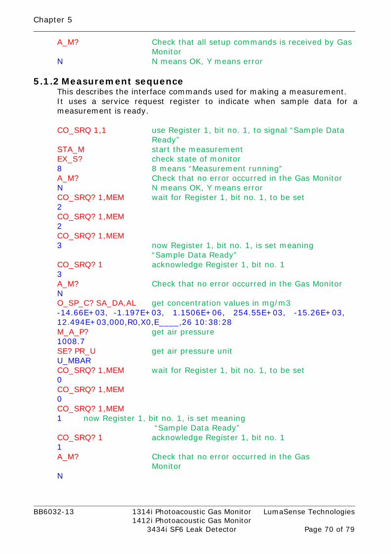
Chapter 5 _________________________________________________________________________________________
_________________________________________________________________________________________ BB6032-13 1314i Photoacoustic Gas Monitor LumaSense Technologies 1412i Photoacoustic Gas Monitor 3434i SF6 Leak Detector Page 70 of 79
A_M? Check that all setup commands is received by Gas Monitor
N N means OK, Y means error
5.1.2 Measurement sequence This describes the interface commands used for making a measurement. It uses a service request register to indicate when sample data for a measurement is ready. CO_SRQ 1,1 use Register 1, bit no. 1, to signal “Sample Data
Ready” STA_M start the measurement EX_S? check state of monitor 8 8 means “Measurement running” A_M? Check that no error occurred in the Gas Monitor N N means OK, Y means error CO_SRQ? 1,MEM wait for Register 1, bit no. 1, to be set 2 CO_SRQ? 1,MEM 2 CO_SRQ? 1,MEM 3 now Register 1, bit no. 1, is set meaning
“Sample Data Ready” CO_SRQ? 1 acknowledge Register 1, bit no. 1 3 A_M? Check that no error occurred in the Gas Monitor N O_SP_C? SA_DA,AL get concentration values in mg/m3 -14.66E+03, -1.197E+03, 1.1506E+06, 254.55E+03, -15.26E+03, 12.494E+03,000,R0,X0,E____,26 10:38:28 M_A_P? get air pressure 1008.7 SE? PR_U get air pressure unit U_MBAR CO_SRQ? 1,MEM wait for Register 1, bit no. 1, to be set 0 CO_SRQ? 1,MEM 0 CO_SRQ? 1,MEM 1 now Register 1, bit no. 1, is set meaning
“Sample Data Ready” CO_SRQ? 1 acknowledge Register 1, bit no. 1 1 A_M? Check that no error occurred in the Gas
Monitor N

Chapter 5 _________________________________________________________________________________________
_________________________________________________________________________________________ BB6032-13 1314i Photoacoustic Gas Monitor LumaSense Technologies 1412i Photoacoustic Gas Monitor 3434i SF6 Leak Detector Page 71 of 79
O_SP_C? SA_DA,AL get concentration values in mg/m3 -14.61E+03, -1.192E+03, 1.1455E+06, 253.54E+03, -15.19E+03, 12.435E+03,000,R0,X0,E____,26 10:39:05 M_A_P? get air pressure 1008.7 SE? PR_U get air pressure unit U_MBAR STOP_M stop measurement EX_S? check state of monitor 8 EX_S? 0 0 means measurement stopped

Chapter 6 _________________________________________________________________________________________
_________________________________________________________________________________________ BB6032-13 1314i Photoacoustic Gas Monitor LumaSense Technologies 1412i Photoacoustic Gas Monitor 3434i SF6 Leak Detector Page 72 of 79
Chapter 6
Multipoint Sampler 1409 commands
April 2017
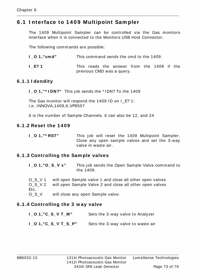
Chapter 6 _________________________________________________________________________________________
_________________________________________________________________________________________ BB6032-13 1314i Photoacoustic Gas Monitor LumaSense Technologies 1412i Photoacoustic Gas Monitor 3434i SF6 Leak Detector Page 73 of 79
6.1 Interface to 1409 Multipoint Sampler
The 1409 Multipoint Sampler can be controlled via the Gas monitors interface when it is connected to the Monitors USB Host Connector. The following commands are possible: I_O 1,”cmd” This command sends the cmd to the 1409. I_E? 1 This reads the answer from the 1409 if the
previous CMD was a query.
6.1.1 Idendity I_O 1,”*IDN?” This job sends the *IDN? To the 1409 The Gas monitor will respond the 1409 ID on I_E? 1: i.e. INNOVA,1409,6,VP9507 6 is the number of Sample Channels. 6 can also be 12, and 24
6.1.2 Reset the 1409
I_O 1,”*RST” This job will reset the 1409 Multipoint Sampler. Close any open sample valves and set the 3-way valve in waste air.
6.1.3 Controlling the Sample valves
I_O 1,”O_S_V x” This job sends the Open Sample Valve command to the 1409.
O_S_V 1 will open Sample valve 1 and close all other open valves O_S_V 2 will open Sample Valve 2 and close all other open valves
Etc. O_S_V will close any open Sample valve. 6.1.4 Controlling the 3 way valve I_O 1,”C_S_V T_M” Sets the 3-way valve to Analyzer I_O 1,”C_S_V T_S_P” Sets the 3-way valve to waste air

Chapter 6 _________________________________________________________________________________________
_________________________________________________________________________________________ BB6032-13 1314i Photoacoustic Gas Monitor LumaSense Technologies 1412i Photoacoustic Gas Monitor 3434i SF6 Leak Detector Page 74 of 79
6.1.5 Warning interface job I_O 1,”W?” This job will check the Warning register in the 1409
I_E? 1 This job will read out the 8 bit warning flag register in decimal values.
Warning flags Bit. no Dec. value Flag description 0 1 Reset done flag 1 2 Na 2 4 Power fail flag 3 - 7 Na
Reset done flag Indicates that the 1409 has completed a reset, following either the Reset system job or by switching on the 1409. This flag is reset when the warning flags are read out from the 1409.
Power fail flag Is set if the internally 12Vdc Power from the 1409’s Power supply is below the specification.The flag reset when the Voltage in back within the specification or by resetting the 1409. If the error is persistent, have the 1409 serviced.
6.1.6 Error interface job I_O 1,”E?” This job will check the Error register in the 1409
I_E? 1 This job will read out the 8 bit Error flag register in decimal values
Error flags
Bit. no Dec. value Flag description 0 1 Na 1 2 Na 2 4 Na 3 8 Na 4 16 Na 5 32 Job specification error 6 64 Software error flag 7 128 Na

Chapter 6 _________________________________________________________________________________________
_________________________________________________________________________________________ BB6032-13 1314i Photoacoustic Gas Monitor LumaSense Technologies 1412i Photoacoustic Gas Monitor 3434i SF6 Leak Detector Page 75 of 79
Job specification error Is set if any interface job sent to the 1409 is not recognized. The flag is reset by reading out the Error flags or by resetting the 1409
Software error flag Is set if the 1409 software develops an error when running. When the flag is set, the 1409 is reset automatically. The flag is reset by reading out the error flags or by resetting the 1409. If the error persist, have the 1409 serviced.

Chapter 7 _________________________________________________________________________________________
_________________________________________________________________________________________ BB6032-13 1314i Photoacoustic Gas Monitor LumaSense Technologies 1412i Photoacoustic Gas Monitor 3434i SF6 Leak Detector Page 76 of 79
Chapter 7
Service Requests
April 2017

Chapter 7 _________________________________________________________________________________________
_________________________________________________________________________________________ BB6032-13 1314i Photoacoustic Gas Monitor LumaSense Technologies 1412i Photoacoustic Gas Monitor 3434i SF6 Leak Detector Page 77 of 79
7.1 Introduction to Service Requests Under certain circumstances, it is necessary for the Monitor to demand attention from the controller or otherwise interrupt the normal sequence of the interface communication. The Monitor does this by raising the Service Request (SRQ) line in the Status Byte. Service requests can, therefore, be used for device synchronization. The SRQ function is commonly used to synchronize the operation of the Monitor with an external computer that has RS–232 controller capabilities. Typically, SRQ indicates that data is ready to be transmitted or an error condition exists. The Monitor generates a Service Request which interrupts the computer. The computer is then free to perform other tasks while waiting for a signal from the Monitor.
Fig. 7.1 Logic diagram of the “Special Event” Event register, Event
Enable Register, Status Byte and Service Request Enable Register.
Fig. 7.1 shows part of the logic diagram for generating Service Requests. The input to 5 of the 8 bits of the Status Byte (bits 1 – 4 and 8) come from the 5 pairs of Event Registers and Event Enable Registers (in this case the “Special Event” Registers) is shown.
• The Event Enable Registers act as masks for the Event Registers.
• The Service Request Enable Register acts as a mask for the Status Byte.

Chapter 7 _________________________________________________________________________________________
_________________________________________________________________________________________ BB6032-13 1314i Photoacoustic Gas Monitor LumaSense Technologies 1412i Photoacoustic Gas Monitor 3434i SF6 Leak Detector Page 78 of 79
7.2 The Status Byte The Status Byte has 8 bits, which are by default set to 0. Seven of the bits (1..6 and 8) are only set when specific conditions occur, bit 7 is used to signal that the Monitor has sent a service request. For example, when a command has been completed, bit 3 in the Status Byte is set. The Status Byte can be read using the message *STB? It can also be read out as a part of a serial poll sequence. There is no interface message enabling you to change the contents of the Status Byte.
7.3 The Service Request Enable Register This register is a mask for the Status Byte. An event that causes a bit to be set in the Status Byte will not alone cause a service request to be sent. If, however, the corresponding bit in the Service Request Enable Register has also been set, then the Status Byte bit will cause a service request to be sent. All bits in the Service Request Enable Register have default value 0. You can read out the contents of the register using the SERVICE_REQUEST_ENABLE? message, and you can define the bit pattern by using the SERVICE_REQUEST_ENABLE message. This determines which conditions cause the Monitor to send a service request.
7.4 The Event and Event Enable Register The input to 5 of the 8 bits of the Status Byte (bits 1–4 and 8) come from 5 pairs of Event Registers and Event Enable Registers. These pairs of registers are linked together in a similar way to the Status Byte and Service Request Enable Register. 20 bits from the 5 Event Registers are used to indicate specific events. Each of these 20 bits has a corresponding bit in an Event Enable Register. As with the Status Byte, a corresponding Event Enable Register bit must be set before an event can generate an output. The contents of the 5 Event Registers are given in Table 2.3 – Table 2.7. Using the CONTROL_SRQ message, you can define the contents of the Event Enable Register specified. Using the CONTROL_SRQ? message, you can read the contents of the Event Enable Register specified. A bit may be set in the Special Event Register, for example, when a key is pressed. In that case, bit 1 is set. If bit 1 is also set in the Special Event Enable Register, then the Special Event bit, which is bit 8, of the Status Byte is set.

LumaSense Technologies A/S Tel.:(+45) 44 20 01 00 Energivej 30 Fax: (+45) 44 20 01 01 DK-2750 Ballerup, Denmark http://www.lumasenseinc.com
1314i 1412i 3434i


![Guidelines for evaluation of radio interface technologies ... · Guidelines for evaluation of radio interface technologies for IMT-2020 “Report ITU-R M.[IMT-2020.EVAL]” Dr. Ying](https://static.fdocuments.in/doc/165x107/5e09d859de52136e136f0e8a/guidelines-for-evaluation-of-radio-interface-technologies-guidelines-for-evaluation.jpg)


