Interface Engineering of Needle‐Like P‐Doped MoS2/CoP ...
10
1 2 3 4 5 6 7 8 9 10 11 12 13 14 15 16 17 18 19 20 21 22 23 24 25 26 27 28 29 30 31 32 33 34 35 36 37 38 39 40 41 42 43 44 45 46 47 48 49 50 51 52 53 54 55 56 57 Interface Engineering of Needle-Like P-Doped MoS 2 /CoP Arrays as Highly Active and Durable Bifunctional Electrocatalyst for Overall Water Splitting Yan Hu, [a] Hongbo Yu, [a] Luoluo Qi, [a] Jiaxin Dong,* [a] Puxuan Yan, [a] Tayirjan Taylor Isimjan,* [b] and Xiulin Yang* [a] Developing a bifunctional water splitting catalyst with high efficiency and low cost are crucial in the electrolysis water industry. Here, we report a rational design and simple preparation method of MoS 2 -based bifunctional electrocatalyst on carbon cloth (CC). The optimized P-doped MoS 2 @CoP/CC catalyst presents low overpotentials for the hydrogen (HER) and oxygen evolution reactions (OER) of 64 and 282 mV in alkaline solution as well as 72 mV HER overpotential in H 2 SO 4 at a current density of 10 mAcm 2 . Furthermore, P-MoS 2 @CoP/CC as a bifunctional catalyst delivered relatively low cell voltages of 1.83 and 1.97 V at high current densities of 500 and mAcm 2 in 30% KOH. The two-electrode system showed a remarkable stability for 30 h, even outperformed the benchmark RuO 2 jj Pt/ C catalyst. The excellent electrochemical performance can be credited to the unique microstructure, high surface area, and the synergy between metal species. This study presents a possible alternative for noble metal-based catalysts to over- come the challenges of industrial applications. Introduction At present, the energy depletion issue has aroused widespread concern and become an obstacle to economic development. [1] Developing a sustainable hydrogen economy has become a hot topic in the scientific world. [2] Electrocatalytic overall water splitting is considered as a sustainable approach of large-scale hydrogen generation hydrogen production from water. The two half reactions in the water splitting are hydrogen evolution reaction (HER) and oxygen evolution reaction (OER). [3] The commercial water splitting systems are currently run at 1.8– 2.4 V cell voltage and 200–400 mAcm 2 current density. [4] Therefore, anything higher than 200 mAcm 2 is considered high current density. Since the OER half-reaction is the rate- determining step, most of the electrolyzers are operated under alkaline conditions, where the HER kinetics is two orders of magnitude slower than in acidic conditions. Therefore, it is critical to develop low-overpotential HER catalysts in alkaline media. In addition, it is especially interesting if the HER catalyst also shows an excellent OER performance because the bifunc- tional catalyst will primarily simplify the production process and decrease the cost. To date, metal-based catalysts such as Pt- based materials and Ru oxides are still recognized as the most effective HER and OER catalysts, respectively. [5] However, their high cost and the inadequate resources of precious metals limit their extensive commercial applications. As a result, consider- able attention has been devoted to developing earth-abundant transition metal-based HER and OER catalysts with performance comparable to these precious metal catalysts. [6] Recently, transition metal-based electrocatalysts and their derivatives, including metal chalcogenides, [7] metal phosphides, [4a,8] and metal carbides [9] were reported as HER/OER bifunctional electrocatalysts. Still, they suffered from slow kinetics and low stability. [10] Among them, Mo-based catalysts revealed great potential. Density function theory (DFT) studies revealed that MoS 2 could exhibit excellent HER performance in acidic media due to the edge sites resulting in optimal hydrogen adsorption free energies ( ~ G � 0.08 eV). [11] However, the HER performance worsens in alkaline solutions because of surface-adsorbed hydroxyl species that hinder the water dissociation steps. [12] To address this problem, Hu et al. [13] proposed a combination of MoS 2 with layered double hydrox- ides (LDHs) materials, including Ni, Co, and Fe that are well- known OER catalysts. As a result, the HER kinetics of MoS 2 -LDH catalysts were accelerated significantly due to the improved binding and dissociation kinetics of hydroxyl species. Besides, a MoO 2 Ni/carbon cloth (CC) heterostructure exhibited high hydrogen evolution performance over the entire pH range. [14] Similarly, an MoS 2 @CoS 2 electrocatalyst with rich structural defects has also shown high hydrogen evolution performance and outstanding durability. [15] The HER performance of Mo- based catalysts can be further improved by phosphorus doping. [16] Moreover, heterostructured MoS 2 /NiS 2 revealed ex- cellent HER and OER performance in alkaline electrolytes because of the synergy between Ni and Mo species and OER nature of the Ni-based catalysts. [17] Many studies have shown [a] Y. Hu, H. Yu, L. Qi, J. Dong, P. Yan, Prof. Dr. X. Yang Guangxi Key Laboratory of Low Carbon Energy Materials School of Chemistry and Pharmaceutical Sciences Guangxi Normal University Guilin 541004 (P. R. China) E-mail: [email protected] [email protected] [b] Dr. T. Taylor Isimjan Saudi Arabia Basic Industries Corporation (SABIC) at King Abdullah University of Science and Technology (KAUST) Thuwal 23955-6900 (Saudi Arabia) E-mail: [email protected] Supporting information for this article is available on the WWW under https://doi.org/10.1002/cssc.202002873 ChemSusChem Full Papers doi.org/10.1002/cssc.202002873 1 ChemSusChem 2021, 14,1–10 © 2021 Wiley-VCH GmbH These are not the final page numbers! ��
Transcript of Interface Engineering of Needle‐Like P‐Doped MoS2/CoP ...

1
2
3
4
5
6
7
8
9
10
11
12
13
14
15
16
17
18
19
20
21
22
23
24
25
26
27
28
29
30
31
32
33
34
35
36
37
38
39
40
41
42
43
44
45
46
47
48
49
50
51
52
53
54
55
56
57
Interface Engineering of Needle-Like P-Doped MoS2/CoPArrays as Highly Active and Durable BifunctionalElectrocatalyst for Overall Water SplittingYan Hu,[a] Hongbo Yu,[a] Luoluo Qi,[a] Jiaxin Dong,*[a] Puxuan Yan,[a] Tayirjan Taylor Isimjan,*[b]
and Xiulin Yang*[a]
Developing a bifunctional water splitting catalyst with highefficiency and low cost are crucial in the electrolysis waterindustry. Here, we report a rational design and simplepreparation method of MoS2-based bifunctional electrocatalyston carbon cloth (CC). The optimized P-doped MoS2@CoP/CCcatalyst presents low overpotentials for the hydrogen (HER) andoxygen evolution reactions (OER) of 64 and 282 mV in alkalinesolution as well as 72 mV HER overpotential in H2SO4 at acurrent density of 10 mAcm� 2. Furthermore, P-MoS2@CoP/CC as
a bifunctional catalyst delivered relatively low cell voltages of1.83 and 1.97 V at high current densities of 500 and mAcm� 2 in30% KOH. The two-electrode system showed a remarkablestability for 30 h, even outperformed the benchmark RuO2 j jPt/C catalyst. The excellent electrochemical performance can becredited to the unique microstructure, high surface area, andthe synergy between metal species. This study presents apossible alternative for noble metal-based catalysts to over-come the challenges of industrial applications.
Introduction
At present, the energy depletion issue has aroused widespreadconcern and become an obstacle to economic development.[1]
Developing a sustainable hydrogen economy has become a hottopic in the scientific world.[2] Electrocatalytic overall watersplitting is considered as a sustainable approach of large-scalehydrogen generation hydrogen production from water. The twohalf reactions in the water splitting are hydrogen evolutionreaction (HER) and oxygen evolution reaction (OER).[3] Thecommercial water splitting systems are currently run at 1.8–2.4 V cell voltage and 200–400 mAcm� 2 current density.[4]
Therefore, anything higher than 200 mAcm� 2 is consideredhigh current density. Since the OER half-reaction is the rate-determining step, most of the electrolyzers are operated underalkaline conditions, where the HER kinetics is two orders ofmagnitude slower than in acidic conditions. Therefore, it iscritical to develop low-overpotential HER catalysts in alkalinemedia. In addition, it is especially interesting if the HER catalystalso shows an excellent OER performance because the bifunc-tional catalyst will primarily simplify the production process anddecrease the cost. To date, metal-based catalysts such as Pt-
based materials and Ru oxides are still recognized as the mosteffective HER and OER catalysts, respectively.[5] However, theirhigh cost and the inadequate resources of precious metals limittheir extensive commercial applications. As a result, consider-able attention has been devoted to developing earth-abundanttransition metal-based HER and OER catalysts with performancecomparable to these precious metal catalysts.[6]
Recently, transition metal-based electrocatalysts and theirderivatives, including metal chalcogenides,[7] metalphosphides,[4a,8] and metal carbides[9] were reported as HER/OERbifunctional electrocatalysts. Still, they suffered from slowkinetics and low stability.[10] Among them, Mo-based catalystsrevealed great potential. Density function theory (DFT) studiesrevealed that MoS2 could exhibit excellent HER performance inacidic media due to the edge sites resulting in optimalhydrogen adsorption free energies (~G�0.08 eV).[11] However,the HER performance worsens in alkaline solutions because ofsurface-adsorbed hydroxyl species that hinder the waterdissociation steps.[12] To address this problem, Hu et al.[13]
proposed a combination of MoS2 with layered double hydrox-ides (LDHs) materials, including Ni, Co, and Fe that are well-known OER catalysts. As a result, the HER kinetics of MoS2-LDHcatalysts were accelerated significantly due to the improvedbinding and dissociation kinetics of hydroxyl species. Besides, aMoO2� Ni/carbon cloth (CC) heterostructure exhibited highhydrogen evolution performance over the entire pH range.[14]
Similarly, an MoS2@CoS2 electrocatalyst with rich structuraldefects has also shown high hydrogen evolution performanceand outstanding durability.[15] The HER performance of Mo-based catalysts can be further improved by phosphorusdoping.[16] Moreover, heterostructured MoS2/NiS2 revealed ex-cellent HER and OER performance in alkaline electrolytesbecause of the synergy between Ni and Mo species and OERnature of the Ni-based catalysts.[17] Many studies have shown
[a] Y. Hu, H. Yu, L. Qi, J. Dong, P. Yan, Prof. Dr. X. YangGuangxi Key Laboratory of Low Carbon Energy MaterialsSchool of Chemistry and Pharmaceutical SciencesGuangxi Normal UniversityGuilin 541004 (P. R. China)E-mail: [email protected]
[email protected][b] Dr. T. Taylor Isimjan
Saudi Arabia Basic Industries Corporation (SABIC) at King AbdullahUniversity of Science and Technology (KAUST)Thuwal 23955-6900 (Saudi Arabia)E-mail: [email protected] information for this article is available on the WWW underhttps://doi.org/10.1002/cssc.202002873
ChemSusChemFull Papersdoi.org/10.1002/cssc.202002873
1ChemSusChem 2021, 14, 1–10 © 2021 Wiley-VCH GmbH
These are not the final page numbers! ��
Wiley VCH Dienstag, 09.02.2021
2199 / 193463 [S. 1/10] 1
1
2
3
4
5
6
7
8
9
10
11
12
13
14
15
16
17
18
19
20
21
22
23
24
25
26
27
28
29
30
31
32
33
34
35
36
37
38
39
40
41
42
43
44
45
46
47
48
49
50
51
52
53
54
55
56
57
that as a promising OER catalyst,[18] introducing cobalt-basedphosphide into HER catalyst can improve its performance.[19] Asa result, MoS2 is coupled with cobalt-based phosphides andphosphorous doping to enhance HER performance in alkalinemedia further. It was envisioned that Mo-based materialsfacilitate HER/OER kinetics in alkaline media by facilitatingbinding and dissociation kinetics of the hydroxyl species. Ascompared to the commonly available methods in theliterature,[20] including high-temperature annealing of metal-organic framework (MOF) precursors, we used a moderatetemperature in situ thermal growth followed by drip-coatingand PH3 chemical vapor deposition approach that results inneedle-like nanoarrays on the CC support. The prepared P-MoS2@CoP/CC materials can be directly used as a self-supported electrode, which is easier to scale up than thetraditional powder system.
Here, we developed a facile and controllable method toconstruct P-doped MoS2@CoP/CC heterostructure catalyst.Three steps of the catalyst preparation are: 1) growing Co(OH)Fnanowire arrays on CC, 2) quantitatively pipetting ammoniumthiomolybdate (3 wt% of (NH4)2MoS4 in DMF), and 3) phospho-orization treatment. The microstructure, crystallinity, and chem-ical state of the resulting P-MoS2@CoP/CC were characterizedand analyzed in detail. Electrochemical studies showed that theoptimized catalyst show low overpotentials of 64 mV (HER,Figure S1 in the Supporting Information) and 282 mV (OER) at10 mAcm� 2 in 1.0m aqueous KOH. Furthermore, the catalystexhibits two-electrode cell voltages of 1.83 and 1.97 V at 500and 1000 mA cm� 2 as well as long-term stability for overallwater splitting in 30% alkaline solution, implying a potentialcommercial application.
Results and Discussion
Synthesis strategy and structural analysis
The synthetic processes of the P-MoS2@CoP/CC are illustrated inFigure 1, and photographs of different samples are shown inFigure S2. The hydrothermal deposition procedure was used toprepare Co(OH)F array in situ grown on CC, and the correspond-ing crystal structure was confirmed as orthorhombic Co(OH)F(JCPDS: 50-0827) by X-ray diffraction (XRD; Figure S3). Then,ammonium thiomolybdate (3 wt% of (NH4)2MoS4 in DMF) was
used to prepare the support‘s surface with different loadings.Finally, a series of hybrid precursors are phosphated to P-dopedMoS2@CoP/CC via PH3 gas produced by NaH2PO2 pyrolysis. Theinductively coupled plasma (ICP) results (Table S1) indicate thatthe maximum MoS2 loading was around 70 wt%. TEM elemen-tal mappings revealed that MoS2 was well dispersed on thesurface of the CoP nanowire arrays. XRD crystal phase analysisshows that the diffraction peaks of the obtained P-MoS2@CoP/CC can be well indexed to the standard diffraction patterns ofCoP (JCPDS: 29-0497) and MoS2 (JCPDS: 37-1492),
[19c,21] respec-tively (Figure 2a). The strong diffraction peak at ~25° belongsto the (002) lattice plane of graphitic carbon.[22] Notably, theXRD patterns of CoP/CC and P-MoS2/CC are very similar to theseof P-MoS2@CoP/CC (Figure S4).
The surface morphologies of the materials were character-ized by scanning electron microscopy (SEM). Figure S5a shows asmooth CC surface before the in situ growth of Co(OH)F species.A thin layer of a needle-like nanoarray structure was formed(Figure S5b) after Co(OH)F deposition. Furthermore, the CoP/CCmorphology remained the same during the phosphorizingtreatment (Figure S5c). After P-doped MoS2 decoration, a thinlayer of P-doped MoS2 was formed on the CoP nanoneedlessurface (Figure 2b, c). As the concentration of the Mo precursorincreases, the surface coverage of the CoP nanoneedlesbecomes denser (Figure S5d,e). Notably, the surface of P-MoS2-modified CC shows severe aggregation without a Co(OH)Fbuffer layer (Figure S5f).
Transmission electron microscopy (TEM) was used to furtherstudy the microstructure features of the P-MoS2@CoP/CC. Fig-ure 2d shows that the thickness of the P-MoS2 species modifiedon the surface of the CoP nanoarray is about 95 nm. The high-resolution (HR)-TEM image shows two types of lattice fringes(Figure 2e) that correspond to the lattice spacing of 0.162 nm(301) and 0.245 nm (102) of the orthorhombic CoP crystalplanes. The other set corresponds to the (105) and (106) crystalplanes of hexagonal MoS2 with lattice spacings of 0.183 and0.164 nm.[23] The formed heterostructure was also confirmed byselected area electron diffraction (SAED; Figure 2f). The TEMimages show the diffraction spots of (200) and (211) corre-sponding to CoP and (106) for MoS2.
[19c,24] Moreover, the high-angle annular dark field (HAADF) TEM elemental mappingssuggest that Co, Mo, P, and S are distributed uniformly in P-MoS2@CoP/CC (Figure 2g).
Figure 1. Schematic illustration of the synthesis of P-MoS2@CoP/CC.
ChemSusChemFull Papersdoi.org/10.1002/cssc.202002873
2ChemSusChem 2021, 14, 1–10 www.chemsuschem.org © 2021 Wiley-VCH GmbH
These are not the final page numbers! ��
Wiley VCH Dienstag, 09.02.2021
2199 / 193463 [S. 2/10] 1

1
2
3
4
5
6
7
8
9
10
11
12
13
14
15
16
17
18
19
20
21
22
23
24
25
26
27
28
29
30
31
32
33
34
35
36
37
38
39
40
41
42
43
44
45
46
47
48
49
50
51
52
53
54
55
56
57
The nitrogen adsorption-desorption isotherms of CoP andP-MoS2@CoP (scraped off the CC) show a typical typeШbehavior (Figure S6). The isotherm data indicate that theBrunauer-Emmett-Teller (BET) surface area of CoP and P-MoS2@CoP are 15 and 13 m2g� 1, accompanying Barrett-Joyner-Halenda (BJH) average pore size distributions are 30 and 12 nm,respectively. This change could be due to the reduced surfacearea resulting from P-MoS2 modification, which shortens thegaps between the needle-like structures.[20b] The high porosityof P-MoS2@CoP is beneficial for mass transfer and access tomore active sites. Moreover, the experimental results indicatean apparent synergistic effect between the two species. Thetwo distinctive features of P-MoS2@CoP jointly improve electro-chemical performance.[25]
XPS analysis
The chemical composition and surface electronic states of P-MoS2@CoP/CC were investigated by X-ray photoelectron spec-troscopy (XPS). XPS survey spectra illustrate that the P-MoS2@CoP/CC’s surface is mainly composed of Co, Mo, P, S, O,C, and N elements (Figure S7a). The C 1s spectrum of P-MoS2@CoP/CC can be deconvoluted into C=C (284.0 eV), C� C(284.8 eV), and C� O (286.0 eV) used as calibration standard(Figure S7b).[26] As for Mo3d in Figure 3a, it can be deconvo-luted into four subpeaks. The peaks at 226.4, 229.1, and230.5 eV are assigned to S2 s, 2H-Mo-S, and 1T-Mo-S,respectively.[27] Compared to P-MoS2/CC, the binding energy of1T-Mo-S of P-MoS2@CoP/CC is slightly shifted to higher bindingenergies (about 0.48 eV). In Figure 3b, Co2p can be fitted tosynthesize six subpeaks and divided into three pairs of CoP(779.4 eV), Co� O (781.8 eV) and one satellite peak
(785.5 eV).[19c,28] Inversely, the binding energy of Co� P of P-MoS2@CoP/CC exhibit a negative shift of 0.5 eV relative to CoP/CC. The S2p1/2 and S2p3/2 peaks of P-MoS2@CoP/CC are locatedat 163.1 and 161.9 eV, respectively, which corresponds to MoS2(Figure 3c).[29] Similarly, as shown in Figure 3d, the P2p XPS ofP-MoS2@CoP/CC with the peaks of P2p1/2 and P2p3/2 located at130.7 and 129.8 eV are ascribed to P� Mo and/or P� Co.[19c,30] Theclear shifts in binding energy illustrate that the chargeredistribution occurs between the two spices due to the stronginteraction between Co and Mo species at the interface of P-MoS2@CoP.
[7b,31] The charge transfer from Mo to Co species onthe interface increases the electrical conductivity of thematerial,[32] thereby helping to improve HER and OER perform-ance.
Electrocatalytic HER analysis
The HER performance of the heterogeneous P-MoS2@CoP/CCcatalyst was measured in 1.0m KOH using a standard three-electrode system. The P-MoS2@CoP-2 catalyst only needs 64and 141 mV to reach the current densities of 10 and100 mAcm� 2 in 1.0m KOH (Figure 4a,b). These results arecomparable with Pt/C (overpotentials: η10=48 mV, η100=
125 mV), and much smaller than those of other control catalysts(Table S2), such as MoS2@Co(OH)F (η10=179 mV, η100=267 mV),CoP (η10=140 mV, η100=222 mV), MoS2 (η10=102 mV, η100=
mV), P-MoS2@CoP-1 (η10=80 mV, η100=161 mV) and P-MoS2@CoP-3 (η10=80 mV, η100=170 mV). More importantly, theoverpotential of P-MoS2@CoP-2 is close to that of Pt/C at acurrent density of 100 mAcm� 2, indicating that this interface-engineered electrode can achieve a similar HER performance asa Pt-based catalyst in alkaline media. Notably, the linear sweep
Figure 2. a) XRD patterns of P-MoS2@CoP/CC. b, c) SEM images of P-MoS2@CoP/CC. d) TEM image, e) HR-TEM image and f) SAED of P-MoS2@CoP/CC.g) HAADF-TEM image and corresponding elemental mappings of P-MoS2@CoP/CC (color online).
ChemSusChemFull Papersdoi.org/10.1002/cssc.202002873
3ChemSusChem 2021, 14, 1–10 www.chemsuschem.org © 2021 Wiley-VCH GmbH
These are not the final page numbers! ��
Wiley VCH Dienstag, 09.02.2021
2199 / 193463 [S. 3/10] 1

1
2
3
4
5
6
7
8
9
10
11
12
13
14
15
16
17
18
19
20
21
22
23
24
25
26
27
28
29
30
31
32
33
34
35
36
37
38
39
40
41
42
43
44
45
46
47
48
49
50
51
52
53
54
55
56
57
voltammetry (LSV) polarization curve fluctuation at highercurrent densities is caused by bubbles forming on the electrodesurface. The gas bubbles minimize the contact surface areabetween the electrode and the electrolyte. The currentincreases again after the gas bubbles leave the surface. Tafelplots were calculated from the polarization curves and are usedto investigate the HER kinetic mechanism and the rate-determining steps. In Figure 4c, the Tafel slope of P-MoS2@CoP-2 (51.2 mVdec� 1) is smaller than other samples, indicating thatthe Volmer–Heyrovsky reaction pathway (H2O+e� ⇄Hads+OH�
and Hads+H2O+e� ⇄H2+OH� ) is the rate-determining step inalkaline media.[14] The exchange current density, as shown inFigure S8a, is obtained by extrapolating the Tafel slope. The
exchange current density of P-MoS2@CoP-2 is 0.50 mAcm� 2 was
higher than most of the control catalysts, indicating fasterelectrode dynamics.[14] In addition, electrochemical impedancespectra (EIS) in Figure S8b showed that P-MoS2@CoP-2 has thelowest charge-transfer resistance (Rct), suggesting an effectiveelectron transfer between catalyst and electrolyte improvingHER performance.[25b,33] The smallest Rct could result from thehigher conductivity of P-doped MoS2 and the strong electronicinteractions between the P-MoS2 and CoP species.
[34]
The double layer capacitance (Cdl) is obtained from a non-faradaic potential region in cyclic voltammetry (CV) graphs ofthe catalyst at different scan rates (Figure S9). Figure 4d showsthat P-MoS2@CoP-2 has the largest Cdl proportional to the
Figure 3. High-resolution XPS spectra of the a) Mo3d and b) Co2p and c) S2p and d) P2p regions of P-MoS2@CoP/CC, P-MoS2/CC, and CoP/CC, respectively.
Figure 4. Electrocatalytic HER performance: a) LSV polarization curves, b) comparison of overpotentials at 10 and 100 mAcm� 2 for P-MoS2@CoP-2 and otherreferences, c) corresponding Tafel slopes, d) Cdl of different catalysts in 1.0m KOH. (e) ECSA-normalized LSV curves (Inset: a bar chart of the ECSA) of CoP, P-MoS2, and P-MoS2@CoP-2. f) Potential-dependent TOF curves of CoP, P-MoS2, P-MoS2@CoP-1, P-MoS2@CoP-2, and P-MoS2@CoP-3, respectively.
ChemSusChemFull Papersdoi.org/10.1002/cssc.202002873
4ChemSusChem 2021, 14, 1–10 www.chemsuschem.org © 2021 Wiley-VCH GmbH
These are not the final page numbers! ��
Wiley VCH Dienstag, 09.02.2021
2199 / 193463 [S. 4/10] 1

1
2
3
4
5
6
7
8
9
10
11
12
13
14
15
16
17
18
19
20
21
22
23
24
25
26
27
28
29
30
31
32
33
34
35
36
37
38
39
40
41
42
43
44
45
46
47
48
49
50
51
52
53
54
55
56
57
electrochemically surface area (ECSA), providing more HER-active sites.[35] As expected, the P-MoS2@CoP-2 catalyst retainsthe maximum ECSA of 2383 cm2 (normalized to per cm2 ofelectrode area), which is much higher than that of CoP(371 cm2) and P-MoS2 (388 cm
2) (inset: Figure 4e). The values ofCdl and ECSA are close to those of some recently reported Co/Mo-based electrocatalysts (Table S3). A similar trend is alsoshown in the HER catalytic activity in ECSA-normalized LSVcurves (Figure 4e).[35] The optimized catalyst has the highestsurface area that exposes more active sites, therefore has ahigher ECSA. To evaluate the intrinsic activity of HER, theturnover frequency (TOF) was used to compare the kinetics ofthe catalysts. The TOF value was calculated using the ICPresults. As shown in Figure 4f, the TOF value of P-MoS2@CoP-2increased more rapidly compared to P-MoS2@CoP-1, P-MoS2@CoP-3, P-MoS2, and CoP when the applied potential wasincreased, suggesting that the introduction of an appropriateamount of Mo species improves the intrinsic activity of theCo� Mo dual active site, thereby enhancing HER catalyticactivity. Furthermore, P-MoS2@CoP-2 can maintain long-termstability under a constant current density of � 100 mAcm� 2 withalmost no degradation in HER catalytic performance (Fig-ure S10). Besides, a CV test was also used to explore thecatalyst‘s stability. The results reveal that the polarization curveremained almost the same after 3000 cycles (Figure S11).However, there are slight changes in catalyst morphology(Figure S12).
Additionally, the needle-like array electrode also revealedexcellent HER performance in acidic media. Similar to the HERactivities in 1.0m KOH, the performance of the catalyst in acidicmedia follows the order Pt/C>P-MoS2@CoP>CoP>P-MoS2(Figure S13a). The overpotential of P-MoS2@CoP/CC is only72 mV at 10 mAcm� 2, higher than that of commercial Pt/C(η10=30 mV) but lower than that of other transition-metal
catalysts (Table S4). Figure S13b shows that the Tafel slope of P-MoS2@CoP/CC is 59.7 mVdec� 1, indicating that the Volmer-Heyrovsky reaction pathway is the rate-determining step inacidic solutions.[19c] Moreover, P-MoS2@CoP/CC shows a smallerRct, indicating that there is a faster electron transfer for HER(Figure S13c). Cdl was calculated from CV curves in the non-faradaic region (Figure S14a–d). Figure S14e shows that the P-MoS2@CoP/CC catalyst has the largest Cdl, demonstrating thatthe P-MoS2@CoP/CC catalyst has more effective active sites atthe interface between P-MoS2 and CoP in P-MoS2@CoP/CC,which synergistically enhances the intrinsic HER activity in acidicmedia.[36] Additionally, the study found that the catalyst couldbe continuously operated at � 100 mAcm� 2 for 80 h in 0.5m
H2SO4 with almost no degradation (Figure S15). The SEM images(Figure S16) before and after the durability test reveal somechanges in the morphology of the catalyst. However, thechanges do not affect the catalytic performance, meaning theinitial morphology is not a critical factor.
We also studied the HER performance in a neutral electro-lyte (pH=7). The LSV polarization curves showed that theoverpotentials of P-MoS2@CoP/CC, as well as the controlcatalysts at � 10 mAcm� 2, were in the range of 138–221 mV.Notably, the overpotential increases rapidly with the increase ofcurrent density (Figure S17), which is still far lower than those inalkaline and acid electrolytes.
Electrocatalytic OER analysis
Another critical reaction of total water splitting is OER, so thecatalyst‘s OER performance has been further explored in analkaline solution. P-MoS2@CoP/CC requires a low overpotentialof 278 mV to reach 10 mAcm� 2 (Figure 5a). When the currentdensity is 70 mAcm� 2, the catalytic performance of P-
Figure 5. Electrocatalytic OER performance in 1.0m KOH. a) LSV polarization curves and b) corresponding Tafel slopes of different catalysts. c) Overpotentialsof recently reported catalysts at 10 mAcm� 2; corresponding Tafel slopes are reported in Table S5. d) Nyquist plots of different catalyst.
ChemSusChemFull Papersdoi.org/10.1002/cssc.202002873
5ChemSusChem 2021, 14, 1–10 www.chemsuschem.org © 2021 Wiley-VCH GmbH
These are not the final page numbers! ��
Wiley VCH Dienstag, 09.02.2021
2199 / 193463 [S. 5/10] 1

1
2
3
4
5
6
7
8
9
10
11
12
13
14
15
16
17
18
19
20
21
22
23
24
25
26
27
28
29
30
31
32
33
34
35
36
37
38
39
40
41
42
43
44
45
46
47
48
49
50
51
52
53
54
55
56
57
MoS2@CoP/CC exceeds that of RuO2. Figure 5b displays thecorresponding Tafel plots, and the Tafel slope value of P-MoS2@CoP/CC is 57.4 mVdec� 1, revealing favorable 4e� oxida-tion kinetics for conversion of water to O2 on the P-MoS2@CoP/CC catalyst.[37] Notably, the P-MoS2@CoP/CC catalyst has afavorable performance comparable to those of recently re-ported non-precious metal-based electrocatalysts (Figure 5c,Table S5).[38] The lower Rct of P-MoS2@CoP/CC is attributed tothe formation of the heterostructure with metallic composite,leading to improved charge transfer at the P-MoS2@CoP inter-face, which eventually accelerates OER reaction (Figure 5d).[39]
These results demonstrate that, to some extent, the interfacialinteractions of P-MoS2@CoP/CC between P-MoS2 and CoP canaccelerate the electron transfer and improve the OER catalyticperformance. However, the OER stability of the P-MoS2@CoP/CCcatalyst over a long period showed a slight decrease in catalyticactivity at a constant current density of 100 mAcm� 2 for 80 h(Figure S18), which could be due to the partial oxidation of Moand Co species under robust oxidative environment. There is nonoticeable change before and after the durability test (Fig-ure S19).
Overall water splitting analysis
The two-electrode water splitting study is a crucial standard toevaluate whether catalysts can be commercialized.[25b] We firsttested the HER and OER performance of the optimized catalystat high current density (Figure S20). We found that the catalystonly requires HER and OER overpotentials of 458 and 570 mV toreach 1000 mAcm� 2, respectively. Subsequently, we used theoptimum P-MoS2@CoP/CC as bifunctional electrocatalyst for
overall water splitting in 1.0m KOH (Figure 6a). The overallwater splitting voltages of the bifunctional P-MoS2@CoP
(+ /� )
catalyst are 1.68, 1.94, and 2.10 V to achieve current densities of100, 500, and 1000 mAcm� 2, respectively (Figure 6b). Notably,the cell voltage of the bifunctional P-MoS2@CoP
(+ /� ) is slightlylower than the state-of-the art RuO2
(+) j jPt/C(� ) when the currentdensity exceeds 1000 mAcm� 2. Besides, the optimized electro-lyzer had a lower cell voltage at 100 mAcm� 2 compared tomost recently reported two-electrode catalytic systems (Fig-ure 6c, Table S6).[2a,40] Figure 6d shows that the bifunctional P-MoS2@CoP
(+ /� ) catalyst could be continuously operated at500 mAcm� 2 for 40 h. We can notice a slight decline after about37 h, which may be related to structural destruction (Fig-ure S21) and surface chemical state changes (Figure S22) of thehybrid material. Notably, the surface content ratio of 1T-MoS2 inP-MoS2@CoP decreased, and CoP almost disappeared after thestability test (Figure S22), indicating that the surface‘s chemicalstates had changed during the catalytic process due to theexcessive oxidation (OER) and reduction (HER) environments.
The excellent water splitting performance can be discussedas follows. Partial substitution of S by the lower electronegativeP will address the low conductivity and high overpotentials ofpristine MoS2. In addition, P doping causes a drop of ΔGH* (H* isadsorbed intermediate) of the neighboring S atoms in the basalplane to 0.43 eV compared to that of pristine MoS2 (2.2 eV).
[16a]
Therefore, H* desorption becomes more accessible, therebyimproving HER performance. In addition, different loadings ofP-MoS2 on the surface of the CoP arrays result in significantlydifferent HER performance and Rct values, indicating that theinterface between CoP and P-MoS2 plays an important role inHER catalysis. The water dissociation is the rate-determiningstep of HER in alkaline media. A DFT study reveals that
Figure 6. a) Schematic description of overall water splitting in a two-electrode system. b) Polarization curves of the bifunctional P-MoS2@CoP(+ /� ) and
RuO2(+) j jPt/C(� ) catalysts for overall water splitting. c) Comparison of the cell voltages between the optimal P-MoS2@CoP
(+ /� ) and other electrocatalystsreported in literature. d) Chronopotentiometry curve of the bifunctional P-MoS2@CoP
(+ /� ) at a current density of 500 mAcm� 2 in 1.0m KOH.
ChemSusChemFull Papersdoi.org/10.1002/cssc.202002873
6ChemSusChem 2021, 14, 1–10 www.chemsuschem.org © 2021 Wiley-VCH GmbH
These are not the final page numbers! ��
Wiley VCH Dienstag, 09.02.2021
2199 / 193463 [S. 6/10] 1

1
2
3
4
5
6
7
8
9
10
11
12
13
14
15
16
17
18
19
20
21
22
23
24
25
26
27
28
29
30
31
32
33
34
35
36
37
38
39
40
41
42
43
44
45
46
47
48
49
50
51
52
53
54
55
56
57
unoccupied 3d and 4d transition metal sites in CoP not only actas oxophilic sites to activate water molecule but also modulatethe electronic structure of CoP to accelerate the kinetics.[41] Thecharge transfer between Mo and Co spaces revealed by XPS inP-MoS2@CoP hybrid structure indicates such synergy thatimproves the water dissociation, thereby causing faster kinetics.Moreover, the OER performance also is enhanced for P-dopedMoS2 due to the improved P intercalation in MoS2 resulting inbetter electron transport.[42] During OER, the surface of CoP ispartially oxidized to Co oxides/oxyhydroxides (CoOx).
[43] Thein situ-formed CoOx and P-MoS2 interfaces can significantlyreduce chemisorption free energy for oxygen-containingintermediates.[31] These results indicate that the interfacesconstructed between CoP and P-MoS2 as well as CoOx and P-MoS2 are critical for water splitting, which are responsible forenhancing electrochemical hydrogen and oxygen evolutions,respectively.[31,43b]
Conclusions
We have successfully constructed a highly active P-MoS2@CoPbifunctional catalyst through a facile and controllable method.The P-MoS2@CoP/carbon cloth (CC) catalyst‘s heterostructuredinterface can enrich the active sites, promote electron transfer,and regulate the binding energy of intermediates. All thosefunctions are beneficial for electrocatalytic reactions. Further,the nanoarray structure in situ grown on the conductive CC canprovide an effective way for charge transport and openchannels for the rapid release of gas bubbles during OER orHER. Various electrochemical test results confirmed a positive P-doping effect. The optimized catalyst revealed HER performancecomparable with Pt/C in both acidic and alkaline solutions athigh current densities. Moreover, the optimized P-MoS2@CoP/CC catalyst outperformed RuO2 on OER. Notably, the cellvoltage of P-MoS2@CoP
(+) j jP-MoS2@CoP(� ) is slightly lower than
the state-of-the-art RuO2(+) j jPt/C(� ) at a current density of
1000 mA cm� 2. This work provides a new strategy to rationallydesign and construct efficient interface engineering catalystsfor overall water splitting.
Experimental Section
Materials
Cobalt nitrate hexahydrate (Co(NO3)2 · 6H2O, 99.0%), ammoniumtetrathiomolybdate ((NH4)2MoS4, 99.95%), urea (CH4N2O, �99.0%),ammonium fluoride (NH4F, �96.0%), and sodium hypophosphitemonohydrate (NaH2PO2, 99.0%) were analytical reagents and usedwithout further purification. Commercial Pt/C (20 wt% Pt) waspurchased from Alfa Aesar. RuO2 powder was synthesized bydirectly calcining RuCl3 in air at 400 °C.
Synthesis of Co(OH)F nanowires arrays on CC (Co(OH)F/CC)
To a 70 mL deionized water were added 4 mmol Co(NO3)2 · 6H2O,4 mmol NH4F, and 10 mmol CH4N2O. The solution was vigorously
stirred for 0.5 h and labeled solution (A). A piece of CC (1 cm×4 cm) was cleaned ultrasonically in 0.5m H2SO4, water, and ethanolfor 15 min to remove impurities, respectively. Then the CC wasplaced in a Teflon-lined stainless-steel autoclave along with 100 mLof solution (A). The autoclave was sealed and maintained at 120 °Cfor 10 h and then cooled down slowly at room temperature. Theresulting pink CC was taken out and rinsed with deionized waterand dried under vacuum at 60 °C. The obtained sample was namedCo(OH)F/CC, and the theoretical loading was 2.0 mgcm� 2.
Synthesis of P-MoS2@CoP Nanoarray on CC
To synthesize P-doped MoS2@CoP, the obtained Co(OH)F/CC wasdrop-coated with an ammonium thiomolybdate solution (3 wt% of(NH4)2MoS4 in DMF), followed by drying under vacuum for 8 h.Then, MoS2@Co(OH)F/CC and NaH2PO2 were put apart in aporcelain boat with 1.0 g NaH2PO2 on the upstream side of thetube furnace. Subsequently, the samples were heated to 350 °C at5 °Cmin� 1 and kept for 2 h at this temperature under a N2
atmosphere, and then naturally cooled to ambient temperature. Inthis hybrid catalyst, the (NH4)2MoS4 loadings were about 3.6, 4.8,and 6.0 mgcm� 2, and the resulting samples are marked as P-MoS2@CoP/CC-1, � 2, and � 3, respectively. Note that if notspecifically stated, P-MoS2@CoP/CC refers to P-MoS2@CoP/CC-2. Asa control, CoP nanoarray-modified CC (CoP/CC) was prepared usinga similar method as mentioned above without (NH4)2MoS4. Inaddition, P-MoS2/CC was synthesized by directly casting ammoniumthiomolybdate solution onto CC (4.8 mgcm� 2), followed by a similarphosphorizing treatment.
Characterization
Morphologies and microstructures of the designed materials werecharacterized by scanning electron microscopy (SEM, Quanta FEG200, Holland) and transmission electron microscopy (TEM, JEOL,JEM-2100F). X-ray powder diffraction (XRD) data was performe by aD/Max 2500 V PC with CuKα radiation. The chemical states of thecatalyst were analyzed by X-ray photoelectron spectroscopy (XPS,model: JPS-9010 TR Photoelectron Spectrometer, Japan). Thecatalyst loadings were determined by inductively coupled plasmaatomic emission spectrometry (ICP-AES, IRIS Intrepid II XSP). Thespecific surface area and pore size distribution were calculatedaccording to the BET and BJH methods, respectively.
Electrochemical measurements
The electrocatalytic activity tests were performed on an BiologicVMP3 electrochemical work station with a standard three-electrodesystem in alkaline and acidic solutions. The catalysts, graphite plate,and standard calomel electrode (SCE) were used as working,counter, and reference electrodes, respectively. A cyclic voltamme-try (CV) test to stabilize the performance of the catalyst wasperformed before testing. Linear sweep voltammetry (LSV) wascarried out at a scan rate of 1 mVs� 1, and electrochemicalimpedance spectroscopy (EIS) measurements were performed nearthe onset potential in the frequency range from 200 kHz to 10 mHz.The potential of ERHE was calibrated by the equation of ERHE=ESCE+0.241 V+0.059·pH V, consistent with the calibration results of thestandard hydrogen electrode (RHE) (Figure S1). All LSV polarizationcurves were corrected against iR compensation. The electrochem-ical double layer capacitance (Cdl) measured by CV at different scanspeeds was used to estimate the electrochemically active surfacearea (ECSA). The overall water splitting test was performed in atwo-electrode system in the potential range of 0–2.0 V with a scanrate of 5 mVs� 1 in 30% KOH solution.
ChemSusChemFull Papersdoi.org/10.1002/cssc.202002873
7ChemSusChem 2021, 14, 1–10 www.chemsuschem.org © 2021 Wiley-VCH GmbH
These are not the final page numbers! ��
Wiley VCH Dienstag, 09.02.2021
2199 / 193463 [S. 7/10] 1

1
2
3
4
5
6
7
8
9
10
11
12
13
14
15
16
17
18
19
20
21
22
23
24
25
26
27
28
29
30
31
32
33
34
35
36
37
38
39
40
41
42
43
44
45
46
47
48
49
50
51
52
53
54
55
56
57
Acknowledgements
This work has been supported by the National Natural ScienceFoundation of China (no. 21965005, 21963003), Natural ScienceFoundation of Guangxi Province (2018GXNSFAA294077,2018GXNSFAA281220), Project of High-Level Talents of Guangxi(F-KA18015, 2018ZD004) and Guangxi Technology Base andTalent Subject (GUIKE AD18126001).
Conflict of Interest
The authors declare no conflict of interest.
Keywords: charge redistribution · electrocatalysis · nanoarrays ·overall water splitting · P doping
[1] a) Y. Li, Z. Wang, J. Hu, S. Li, Y. Du, X. Han, P. Xu, Adv. Funct. Mater. 2020,30, 1910498; b) M. Yang, Y. Jiang, M. Qu, Y. Qin, Y. Wang, W. Shen, R. He,W. Su, M. Li, Appl. Catal. B 2020, 269, 118803.
[2] a) G. Qian, G. Yu, J. Lu, L. Luo, T. Wang, C. Zhang, R. Ku, S. Yin, W. Chen,S. Mu, J. Mater. Chem. A 2020, 8, 14545–14554; b) Y. Li, X. Tan, H. Tan, H.Ren, S. Chen, W. Yang, S. C. Smith, C. Zhao, Energy Environ. Sci. 2020, 13,1799–1807.
[3] a) W. Zhu, W. Chen, H. Yu, Y. Zeng, F. Ming, H. Liang, Z. Wang, Appl.Catal. B 2020, 278, 119326; b) H. Sun, C. Tian, G. Fan, J. Qi, Z. Liu, Z. Yan,F. Cheng, J. Chen, C.-P. Li, M. Du, Adv. Funct. Mater. 2020, 30, 1910596;c) S. Kurungot, R. Illathvalappil, F. Kanheerampockil, P. S. Walko, S. K.Bhat, R. N. Devi, Chem. Eur. J. 2020, 26, 7900–7911.
[4] a) F. Yu, H. Zhou, Y. Huang, J. Sun, F. Qin, J. Bao, W. A. Goddard, S. Chen,Z. Ren, Nat. Commun. 2018, 9, 2551; b) H. Zhou, F. Yu, Q. Zhu, J. Sun, F.Qin, L. Yu, J. Bao, Y. Yu, S. Chen, Z. Ren, Energy Environ. Sci. 2018, 11,2858–2864.
[5] a) Q. Dang, Y. Sun, X. Wang, W. Zhu, Y. Chen, F. Liao, H. Huang, M. Shao,Appl. Catal. B 2019, 257, 117905; b) Y. Lee, J. Suntivich, K. J. May, E. E.Perry, Y. Shao-Horn, J. Phys. Chem. Lett. 2012, 3, 399–404.
[6] a) S. Y. Tee, K. Y. Win, W. S. Teo, L.-D. Koh, S. Liu, C. P. Teng, M.-Y. Han,Adv. Sci. 2017, 4, 1600337; b) Z. Wan, H. Yu, Q. He, Y. Hu, P. Yan, X. Shao,T. T. Isimjan, B. Zhang, X. Yang, Int. J. Hydrogen Energy 2020, 45, 22427–22436.
[7] a) K. N. Dinh, Y. Sun, Z. Pei, Z. Yuan, A. Suwardi, Q. Huang, X. Liao, Z.Wang, Y. Chen, Q. Yan, Small 2020, 16, 1905885; b) B. Wang, H. Huang,T. Sun, P. Yan, T. T. Isimjan, J. Tian, X. Yang, J. Colloid Interface Sci. 2020,567, 339–346.
[8] H. Zhang, A. W. Maijenburg, X. Li, S. L. Schweizer, R. B. Wehrspohn, Adv.Funct. Mater. 2020, 30, 2003261.
[9] a) Y. Yu, J. Zhou, Z. Sun, Adv. Funct. Mater. 2020, 2000570; b) L. He, W.Zhang, Q. Mo, W. Huang, L. Yang, Q. Gao, Angew. Chem. Int. Ed. 2020,59, 3544–3548; Angew. Chem. 2020, 132, 3572–3576.
[10] a) X. F. Lu, Y. Chen, S. Wang, S. Gao, X. W. Lou, Adv. Mater. 2019, 31,1902339; b) X. Tao, H. Xu, S. Luo, Y. Wu, C. Tian, X. Lu, Y. Qing, Appl.Catal. B 2020, 279, 119367.
[11] a) X. Huang, Z. Zeng, H. Zhang, Chem. Soc. Rev. 2013, 42, 1934–1946;b) T. F. Jaramillo, K. P. Jørgensen, J. Bonde, J. H. Nielsen, S. Horch, I.Chorkendorff, Science 2007, 317, 100–102.
[12] M. T. M. Koper, Nat. Chem. 2013, 5, 255–256.[13] J. Hu, C. Zhang, L. Jiang, H. Lin, Y. An, D. Zhou, M. K. H. Leung, S. Yang,
Joule 2017, 1, 383–393.[14] B. Wang, H. Huang, M. Huang, P. Yan, T. T. Isimjan, X. Yang, Sci. China
Chem. 2020, 63, 841–849.[15] J. Hou, B. Zhang, Z. Li, S. Cao, Y. Sun, Y. Wu, Z. Gao, L. Sun, ACS Catal.
2018, 8, 4612–4621.[16] a) K. Guruprasad, T. Maiyalagan, S. Shanmugam, ACS Appl. Energy Mater.
2019, 2, 6184–6194; b) A. Wu, C. Tian, H. Yan, Y. Jiao, Q. Yan, G. Yang, H.Fu, Nanoscale 2016, 8, 11052–11059.
[17] J. Lin, P. Wang, H. Wang, C. Li, X. Si, J. Qi, J. Cao, Z. Zhong, W. Fei, J.Feng, Adv. Sci. 2019, 6, 1900246.
[18] a) Y. Bai, H. Zhang, Y. Feng, L. Fang, Y. Wang, J. Mater. Chem. A 2016, 4,9072–9079; b) K. He, T. Tadesse Tsega, X. Liu, J. Zai, X.-H. Li, X. Liu, W. Li,N. Ali, X. Qian, Angew. Chem. Int. Ed. 2019, 58, 11903–11909; Angew.Chem. 2019, 131, 12029–12035.
[19] a) X. Yang, A.-Y. Lu, Y. Zhu, M. N. Hedhili, S. Min, K.-W. Huang, Y. Han, L.-J. Li, Nano Energy 2015, 15, 634–641; b) G. Huang, W. Liang, Y. Wu, J. Li,Y. Q. Jin, H. Zeng, H. Zhang, F. Xie, J. Chen, N. Wang, Y. Jin, H. Meng, J.Catal. 2020, 390, 23–29; c) X. Huang, X. Xu, X. Luan, D. Cheng, NanoEnergy 2020, 68, 104332.
[20] a) H. Yuan, S. Wei, B. Tang, Z. Ma, J. Li, M. Kundu, X. Wang,ChemSusChem 2020, 13, 3662–3670; b) D. Chen, H. Zhou, J. Xiao, A.Yuan, ChemistrySelect 2020, 5, 8233–8240; c) J. Feng, H. Zhou, J. Wang,T. Bian, J. Shao, A. Yuan, Int. J. Hydrogen Energy 2018, 43, 20538–20545.
[21] M. D. Sharma, C. Mahala, M. Basu, Inorg. Chem. 2020, 59, 4377–4388.[22] T. Tang, Q. Gan, X. Guo, H. Dong, J. Zhang, Y. Zhao, J. Tian, X. Yang,
Sustain. Energ. Fuels 2018, 2, 229–236.[23] a) X. Guan, L. Zhao, P. Zhang, J. Liu, X. Song, L. Gao, Mater. Today Energy
2020, 16, 100379; b) L. Guo, X. Bai, H. Xue, J. Sun, T. Song, S. Zhang, L.Qin, K. Huang, F. He, Q. Wang, Chem. Commun. 2020, 56, 7702–7705.
[24] H. Zhao, Z. Li, X. Dai, M. Cui, F. Nie, X. Zhang, Z. Ren, Z. Yang, Y. Gan, X.Yin, Y. Wang, W. Song, J. Mater. Chem. A 2020, 8, 6732–6739.
[25] a) Y. Liu, Y. Xu, Y. Han, Z. Zhang, J. Xu, Y. Du, J. Bao, X. Zhou, J. PowerSources 2019, 436, 226860; b) P. Yan, M. Huang, B. Wang, Z. Wan, M.Qian, H. Yan, T. T. Isimjan, J. Tian, X. Yang, J. Energy Chem. 2020, 47,299–306.
[26] a) A. Lim, J. Kim, H. J. Lee, H.-J. Kim, S. J. Yoo, J. H. Jang, H. Y. Park, Y.-E.Sung, H. S. Park, Appl. Catal. B 2020, 272, 118955; b) J.-L. Song, Z.-Q.Huang, B. Wang, D.-S. Pan, L.-L. Zhou, Z.-H. Guo, ChemSusChem 2020,13, 2564–2570.
[27] a) H. Yu, Y. Xue, L. Hui, C. Zhang, Y. Zhao, Z. Li, Y. Li, Adv. Funct. Mater.2018, 28, 1707564; b) K. Qi, X. Cui, L. Gu, S. Yu, X. Fan, M. Luo, S. Xu, N.Li, L. Zheng, Q. Zhang, J. Ma, Y. Gong, F. Lv, K. Wang, H. Huang, W.Zhang, S. Guo, W. Zheng, P. Liu, Nat. Commun. 2019, 10, 5231.
[28] J. Wang, H. Cheng, S. Ren, L. Zhang, L.-X. Ding, H. Wang, J. Mater. Chem.A 2020, 8, 16018–16023.
[29] A. Wu, Y. Gu, Y. Xie, C. Tian, H. Yan, D. Wang, X. Zhang, Z. Cai, H. Fu, ACSAppl. Mater. Interfaces 2019, 11, 25986–25995.
[30] Y. Du, H. Qu, Y. Liu, Y. Han, L. Wang, B. Dong, Appl. Surf. Sci. 2019, 465,816–823.
[31] J. Zhang, T. Wang, D. Pohl, B. Rellinghaus, R. Dong, S. Liu, X. Zhuang, X.Feng, Angew. Chem. Int. Ed. 2016, 55, 6702–6707; Angew. Chem. 2016,128, 6814–6819.
[32] X. Xia, Z. Zheng, Y. Zhang, X. Zhao, C. Wang, Int. J. Hydrogen Energy2014, 39, 9638–9650.
[33] Y. Zhao, J. Zhang, X. Guo, H. Fan, W. Wu, H. Liu, G. Wang, J. Mater.Chem. A 2017, 5, 19672–19679.
[34] P. Liu, J. Zhu, J. Zhang, P. Xi, K. Tao, D. Gao, D. Xue, ACS Energy Lett.2017, 2, 745–752.
[35] S. L. Zhang, B. Y. Guan, X. F. Lu, S. Xi, Y. Du, X. W. Lou, Adv. Mater. 2020,32, 2002235.
[36] X. Huang, H. Xu, D. Cao, D. Cheng, Nano Energy 2020, 78, 105253.[37] J. Liu, C. Wang, H. Sun, H. Wang, F. Rong, L. He, Y. Lou, S. Zhang, Z.
Zhang, M. Du, Appl. Catal. B 2020, 279, 119407.[38] a) K. Zhou, Y.-J. Tang, Y. Wang, J. Mater. Chem. A 2020, 8, 7925–7934;
b) W. Zong, D. Rao, H. Guo, Y. Ouyang, Y.-E. Miao, W. Wang, J. Wang, F.Lai, T. Liu, Nanoscale 2020, 12, 10977–10986; c) H. Yuan, S. Wei, B. Tang,Z. Ma, J. Li, M. Kundu, X. Wang, ChemSusChem 2020, 13, 3662–3670;d) X. Zheng, P. Cui, Y. Qian, G. Zhao, X. Zheng, X. Xu, Z. Cheng, Y. Liu,S. X. Dou, W. Sun, Angew. Chem. Int. Ed. 2020, 59, 14533–14540; Angew.Chem. 2020, 132, 14641–14648; e) X. Zheng, X. Han, Y. Cao, Y. Zhang, D.Nordlund, J. Wang, S. Chou, H. Liu, L. Li, C. Zhong, Y. Deng, W. Hu, Adv.Mater. 2020, 32, 2000607; f) P. Thangasamy, S. Oh, S. Nam, H.Randriamahazaka, I.-K. Oh, Small 2020, 16, 2001665; g) C. He, M. Huang,G. Wang, Y. Zhang, X. Li, L. Fan, Y. Li, Nanoscale 2020, 12, 11735–11745;h) Q. Xia, H. Liu, M. Jin, L. Lai, Y. Qiu, H. Zhai, H. Li, X. Liu, Nanoscale2020, 12, 8969–8974; i) Y. R. Hong, K. M. Kim, J. H. Ryu, S. Mhin, J. Kim,G. Ali, K. Y. Chung, S. Kang, H. Han, Adv. Funct. Mater. 2020, 30, 2004330;j) X. Wang, F. Li, W. Li, W. Gao, Y. Tang, R. Li, J. Mater. Chem. A 2017, 5,17982–17989; k) T. Ouyang, X.-T. Wang, X.-Q. Mai, A.-N. Chen, Z.-Y. Tang,Z.-Q. Liu, Angew. Chem. Int. Ed. 2020, 59, 11948–11957; Angew. Chem.2020, 132, 12046–12055; l) H. Shang, W. Sun, R. Sui, J. Pei, L. Zheng, J.Dong, Z. Jiang, D. Zhou, Z. Zhuang, W. Chen, J. Zhang, D. Wang, Y. Li,Nano Lett. 2020, 20, 5443–5450.
[39] M. Kim, M. A. R. Anjum, M. Choi, H. Y. Jeong, S. H. Choi, N. Park, J. S. Lee,Adv. Funct. Mater. 2020, 30, 2002536.
ChemSusChemFull Papersdoi.org/10.1002/cssc.202002873
8ChemSusChem 2021, 14, 1–10 www.chemsuschem.org © 2021 Wiley-VCH GmbH
These are not the final page numbers! ��
Wiley VCH Dienstag, 09.02.2021
2199 / 193463 [S. 8/10] 1
1
2
3
4
5
6
7
8
9
10
11
12
13
14
15
16
17
18
19
20
21
22
23
24
25
26
27
28
29
30
31
32
33
34
35
36
37
38
39
40
41
42
43
44
45
46
47
48
49
50
51
52
53
54
55
56
57
[40] a) A. I. Inamdar, H. S. Chavan, B. Hou, C. H. Lee, S. U. Lee, S. Cha, H. Kim,H. Im, Small 2020, 16, 1905884; b) J. H. Lin, H. H. Wang, J. Cao, F. He,J. C. Feng, J. L. Qi, J. Colloid Interface Sci. 2020, 571, 260-266; c) F.-T. Tsai,Y.-T. Deng, C.-W. Pao, J.-L. Chen, J.-F. Lee, K.-T. Lai, W.-F. Liaw, J. Mater.Chem. A 2020, 8, 9939-9950; d) L. Chen, Y. Song, Y. Liu, L. Xu, J. Qin, Y.Lei, Y. Tang, J. Energy Chem. 2020, 50, 395-401; e) R. Li, J. Zang, W. Li, J.Li, Q. Zou, S. Zhou, J. Su, Y. Wang, ChemSusChem 2020, 13, 3718-3725;f) G. Zhan, J. Zhang, Y. Wang, C. Yu, J. Wu, J. Cui, X. Shu, Y. Qin, H.Zheng, J. Sun, J. Yan, Y. Zhang, C. S. Tiwary, Y. Wu, J. Colloid Interface Sci.2020, 566, 411-418; g) Y. Wang, S. Chen, S. Zhao, Q. Chen, J. Zhang, J.Mater. Chem. A 2020, 8, 15845-15852; h) Y. Chen, J. Yu, J. Jia, F. Liu, Y.Zhang, G. Xiong, R. Zhang, R. Yang, D. Sun, H. Liu, W. Zhou, Appl. Catal.B: Environ. 2020, 272, 118956.
[41] Y. Men, P. Li, J. Zhou, S. Chen, W. Luo, Cell Rep. Phys. Sci. 2020, 1,100136.
[42] L. Ye, S. Chen, W. Li, M. Pi, T. Wu, D. Zhang, J. Phys. Chem. C 2015, 119,9560–9567.
[43] a) J. Wang, F. Ciucci, Appl. Catal. B 2019, 254, 292–299; b) A. Muthurasu,V. Maruthapandian, H. Y. Kim, Appl. Catal. B 2019, 248, 202–210.
Manuscript received: December 15, 2020Revised manuscript received: January 21, 2021Accepted manuscript online: January 23, 2021Version of record online: ■■■, ■■■■
ChemSusChemFull Papersdoi.org/10.1002/cssc.202002873
9ChemSusChem 2021, 14, 1–10 www.chemsuschem.org © 2021 Wiley-VCH GmbH
These are not the final page numbers! ��
Wiley VCH Dienstag, 09.02.2021
2199 / 193463 [S. 9/10] 1
1
2
3
4
5
6
7
8
9
10
11
12
13
14
15
16
17
18
19
20
21
22
23
24
25
26
27
28
29
30
31
32
33
34
35
36
37
38
39
40
41
42
43
44
45
46
47
48
49
50
51
52
53
54
55
56
57
FULL PAPERS
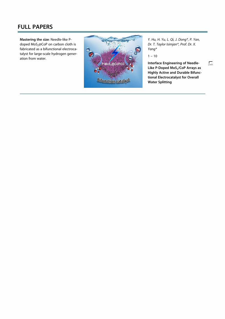
Mastering the size: Needle-like P-doped MoS2@CoP on carbon cloth isfabricated as a bifunctional electroca-talyst for large-scale hydrogen gener-ation from water.
Y. Hu, H. Yu, L. Qi, J. Dong*, P. Yan,Dr. T. Taylor Isimjan*, Prof. Dr. X.Yang*
1 – 10
Interface Engineering of Needle-Like P-Doped MoS2/CoP Arrays asHighly Active and Durable Bifunc-tional Electrocatalyst for OverallWater Splitting
Wiley VCH Dienstag, 09.02.2021
2199 / 193463 [S. 10/10] 1