Interface Control Document Between CubeLab...
15
Document: 8400-NRP-ICD-1 Interface Control Document Between CubeLab Modules and the NanoRacks Platform Classification: Public Domain Date: 2011-1-11 Revision: 1 Page 1 of 15 Interface Control Document Between CubeLab Modules and the NanoRacks Platform Space Systems Laboratory 453 F. Paul Anderson Tower University of Kentucky Lexington, KY, United States 40506 (859) 257-8042 Document No.: 8400-NRP-ICD-1 Issue: Revision-1 Date: 2011-1-1 Classification: Public Domain © 2011 Space Systems Laboratory Prepared: Zach Jacobs Reviewed: Dr. James E. Lumpp Jr. Max Bezold 859-257-3895 [email protected]
Transcript of Interface Control Document Between CubeLab...
Document: 8400-NRP-ICD-1
Interface Control Document Between CubeLab Modules and the NanoRacks
Platform
Classification: Public Domain Date: 2011-1-11 Revision: 1 Page 1 of 15
Interface Control Document Between CubeLab Modules and the NanoRacks Platform
Space Systems Laboratory
453 F. Paul Anderson Tower University of Kentucky
Lexington, KY, United States 40506 (859) 257-8042
Document No.: 8400-NRP-ICD-1 Issue: Revision-1 Date: 2011-1-1 Classification: Public Domain © 2011 Space Systems Laboratory Prepared: Zach Jacobs Reviewed: Dr. James E. Lumpp Jr. Max Bezold 859-257-3895 [email protected]
Document: 8400-NRP-ICD-1
Interface Control Document Between CubeLab Modules and the NanoRacks
Platform
Classification: Public Domain Date: 2011-1-11 Revision: 1 Page 2 of 15 0.0 Revision History
Issue Date Author Details
Draft-A 2010-02-26 Max Bezold Zach Jacobs Document Created. Initial Release.
Revision-1 2011-1-1 Max Bezold Twyman Clements
Changes throughout document to improve clarity, maximum dimensions for CubeLabs updated.
Document: 8400-NRP-ICD-1
Interface Control Document Between CubeLab Modules and the NanoRacks
Platform
Classification: Public Domain Date: 2011-1-11 Revision: 1 Page 3 of 15 1.0 Introduction
The CubeLab Standard was developed to expand the research capabilities in microgravity on the International Space Station (ISS) to a broader and more diverse collection of researchers. The CubeLab standard leverages several well know, well defined, and well supported standards to simplify access to space for those developers; these include the CubeSat standard for the physical form-factor and the USB standard for power and data connection. 1.1 Document Purpose
This document was created to define the interface requirements between the NanoRacks Platform and individual CubeLab Modules. The primary responsibility of CubeLab Module developers is to ensure they conform to the requirements of this document and to incorporate safe engineering practices throughout the design, fabrication, and testing processes. Kentucky Space, acting as the CubeLab Module integrator, will ensure the CubeLab Module’s compliance with the requirements of this document and all applicable testing procedures. Compliance with this document is required for flight and installation of a CubeLab Module to the NanoRacks Platform. CubeLab Module developers shall adhere to the requirements of the latest revision of this document. 1.2 Scope
This document covers CubeLab Module compatibility with the NanoRacks Platforms currently in operation on the ISS.
1.3 Abbreviations and Acronyms ELC EXPRESS Rack Laptop Computer
EMC Electromagnetic Compatibility
EMI Electromagnetic Interference
EXPRESS Expedite the Processing of Experiments to the Space Station
ISS International Space Station
JEM Japanese Experiment Module
JSC Johnson Space Center
KSC Kennedy Space Center
MSFC Marshall Space Flight Center
NASA National Aeronautics and Space Administration
SSL Space Systems Lab (University of Kentucky)
TDRSS Tracking and DATA Relay Satellite System network
USB Universal Serial Bus
Document: 8400-NRP-ICD-1
Interface Control Document Between CubeLab Modules and the NanoRacks
Platform
Classification: Public Domain Date: 2011-1-11 Revision: 1 Page 4 of 15 1.4 Referenced Documents
Many of the requirements spelled out in this document flow down from NASA standards regarding hardware on manned spacecraft. With that, all standards referenced in this document can be found at the following link:
http://ssl.engr.uky.edu/cubelab/documents
2.0 The NanoRacks Platform 2.1 Overview
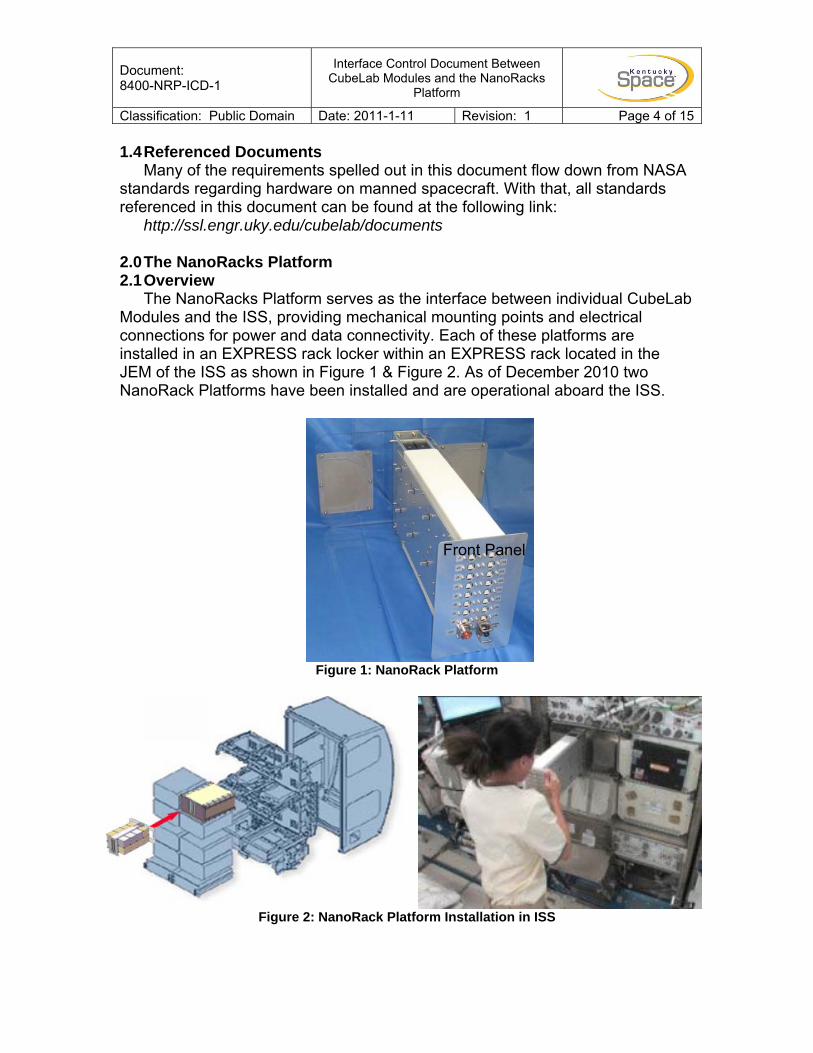
The NanoRacks Platform serves as the interface between individual CubeLab Modules and the ISS, providing mechanical mounting points and electrical connections for power and data connectivity. Each of these platforms are installed in an EXPRESS rack locker within an EXPRESS rack located in the JEM of the ISS as shown in Figure 1 & Figure 2. As of December 2010 two NanoRack Platforms have been installed and are operational aboard the ISS.
Figure 1: NanoRack Platform
Figure 2: NanoRack Platform Installation in ISS
Front Panel

Document: 8400-NRP-ICD-1
Interface Control Document Between CubeLab Modules and the NanoRacks
Platform
Classification: Public Domain Date: 2011-1-11 Revision: 1 Page 5 of 15 2.2 Coordinate System
The coordinate system used on the NanoRacks Platform concerning dimensioning and spacing for individual CubeLab Modules follows the convention shown in Figure 3. CubeLab Module requirements are specified using this convention and developers shall use the same convention in their designs.
Figure 3: NanoRack Platform Coordinate System with and without CubeLab Modules
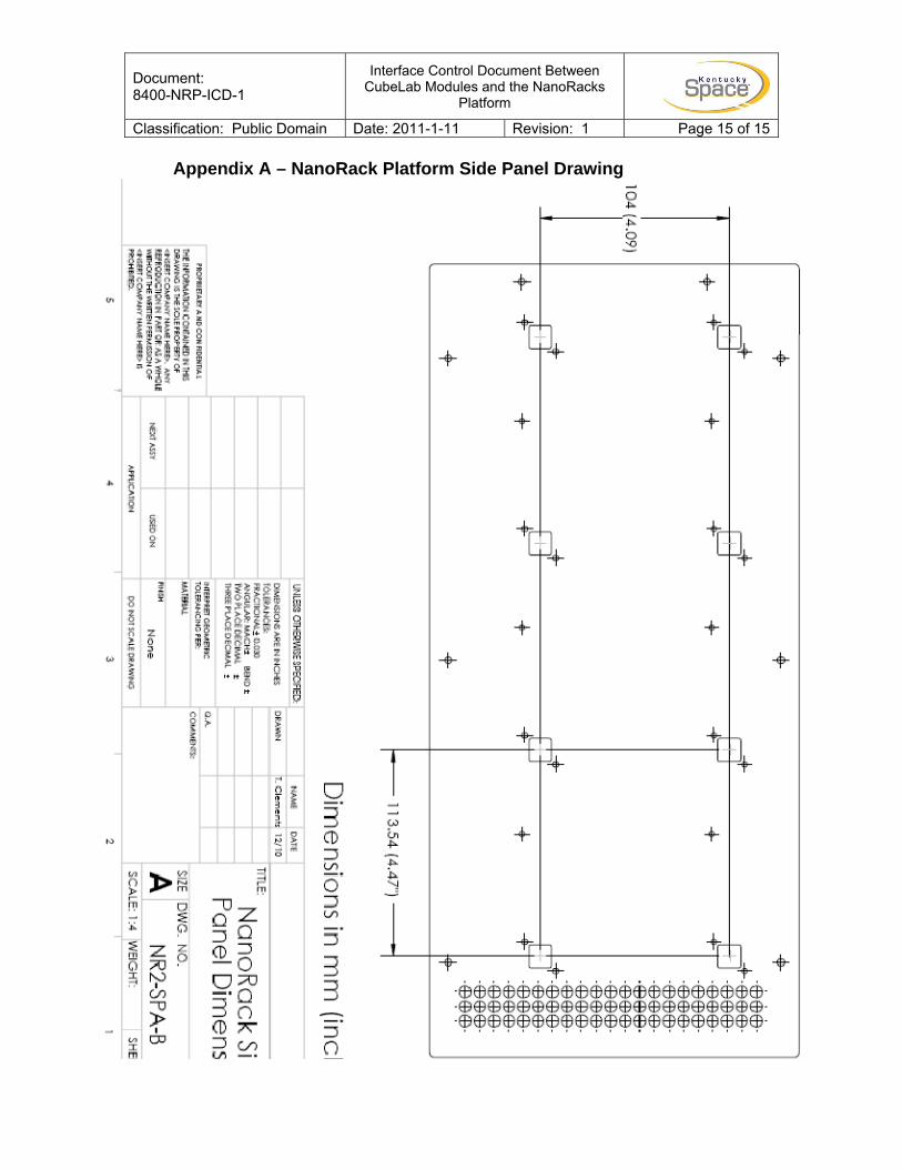
2.3 USB Spacing and Orientation The NanoRack Platform includes 8 USB type B male connectors per side for
a total of 16 attachments for Cubelab Modules. The connections are oriented as shown in Figure 4 with the flat edge of the USB facing towards the front panel of the NanoRack Platform. A Mechanical Drawing of the side panel of a NanoRacks Platform showing the spacing of the connectors is included in Appendix A.
Figure 4: NanoRack Platform USB Orientation
Y
Z
X
X Z
Y
Document: 8400-NRP-ICD-1
Interface Control Document Between CubeLab Modules and the NanoRacks
Platform
Classification: Public Domain Date: 2011-1-11 Revision: 1 Page 6 of 15 3.0 The CubeLab Standard 3.1 Dimensioning from USB Connections
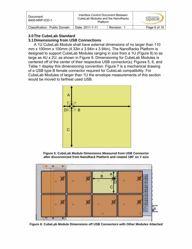
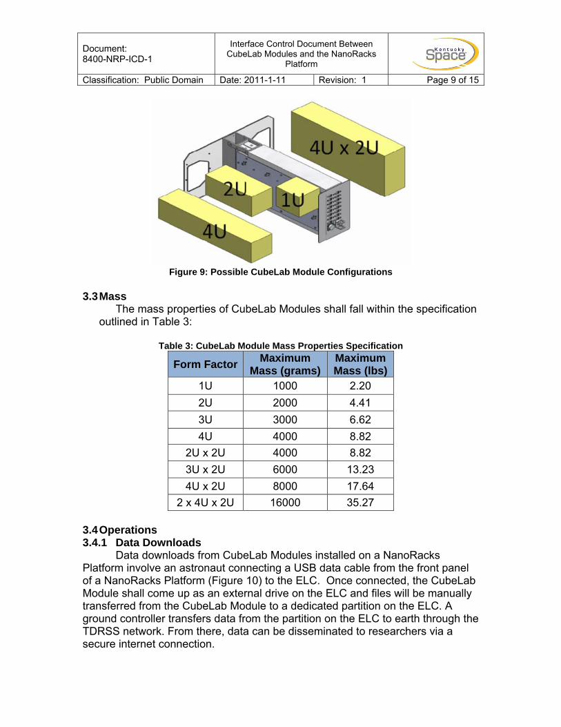
A 1U CubeLab Module shall have external dimensions of no larger than 110 mm x 100mm x 100mm (4.33in x 3.94in x 3.94in). The NanoRacks Platform is designed to support CubeLab Modules ranging in size from a 1U (Figure 8) to as large as 4U x 2U; as shown in Figure 9. Dimensioning for CubeLab Modules is centered off of the center of their respective USB connector(s); Figures 5, 6, and Table 1 display this dimensioning convention. Figure 7 is a mechanical drawing of a USB type B female connector required for CubeLab compatibility. For CubeLab Modules of larger than 1U the envelope measurements of this section would be moved to farthest used USB.
Figure 5: CubeLab Module Dimensions Measured from USB Connector after disconnected from NanoRack Platform and rotated 180 ̊ on Y axis
Figure 6: CubeLab Module Dimensions off USB Connectors with Other Modules Attached
D
A
B
C
A
D C
B
Document: 8400-NRP-ICD-1
Interface Control Document Between CubeLab Modules and the NanoRacks
Platform
Classification: Public Domain Date: 2011-1-11 Revision: 1 Page 7 of 15
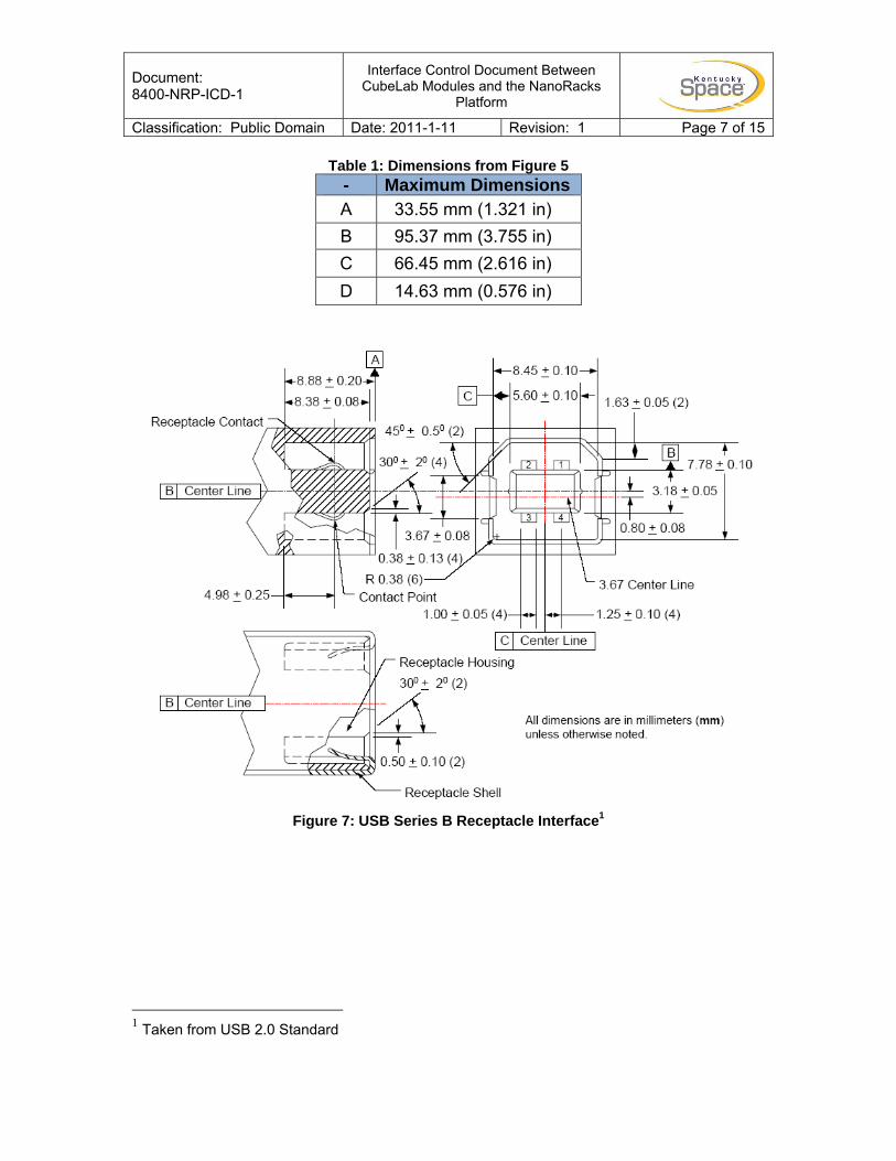
Table 1: Dimensions from Figure 5 - Maximum Dimensions A 33.55 mm (1.321 in) B 95.37 mm (3.755 in) C 66.45 mm (2.616 in) D 14.63 mm (0.576 in)
Figure 7: USB Series B Receptacle Interface1
1 Taken from USB 2.0 Standard
Document: 8400-NRP-ICD-1
Interface Control Document Between CubeLab Modules and the NanoRacks
Platform
Classification: Public Domain Date: 2011-1-11 Revision: 1 Page 8 of 15 3.2 Maximum Volume
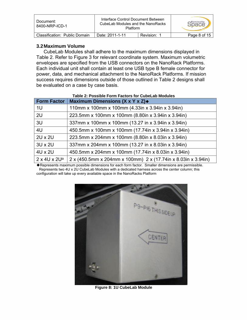
CubeLab Modules shall adhere to the maximum dimensions displayed in Table 2. Refer to Figure 3 for relevant coordinate system. Maximum volumetric envelopes are specified from the USB connectors on the NanoRack Platforms. Each individual unit shall contain at least one USB type B female connector for power, data, and mechanical attachment to the NanoRack Platforms. If mission success requires dimensions outside of those outlined in Table 2 designs shall be evaluated on a case by case basis.
Table 2: Possible Form Factors for CubeLab Modules
Form Factor Maximum Dimensions (X x Y x Z)1U 110mm x 100mm x 100mm (4.33in x 3.94in x 3.94in) 2U 223.5mm x 100mm x 100mm (8.80in x 3.94in x 3.94in) 3U 337mm x 100mm x 100mm (13.27 in x 3.94in x 3.94in) 4U 450.5mm x 100mm x 100mm (17.74in x 3.94in x 3.94in) 2U x 2U 223.5mm x 204mm x 100mm (8.80in x 8.03in x 3.94in) 3U x 2U 337mm x 204mm x 100mm (13.27 in x 8.03in x 3.94in) 4U x 2U 450.5mm x 204mm x 100mm (17.74in x 8.03in x 3.94in) 2 x 4U x 2U 2 x (450.5mm x 204mm x 100mm) 2 x (17.74in x 8.03in x 3.94in)
Represents maximum possible dimensions for each form factor. Smaller dimensions are permissible. �Represents two 4U x 2U CubeLab Modules with a dedicated harness across the center column; this configuration will take up every available space in the NanoRacks Platform
Figure 8: 1U CubeLab Module
Document: 8400-NRP-ICD-1
Interface Control Document Between CubeLab Modules and the NanoRacks
Platform
Classification: Public Domain Date: 2011-1-11 Revision: 1 Page 9 of 15
Figure 9: Possible CubeLab Module Configurations
3.3 Mass
The mass properties of CubeLab Modules shall fall within the specification outlined in Table 3:
Table 3: CubeLab Module Mass Properties Specification
Form Factor Maximum Mass (grams)
Maximum Mass (lbs)
1U 1000 2.20 2U 2000 4.41 3U 3000 6.62 4U 4000 8.82
2U x 2U 4000 8.82 3U x 2U 6000 13.23 4U x 2U 8000 17.64
2 x 4U x 2U 16000 35.27
3.4 Operations 3.4.1 Data Downloads
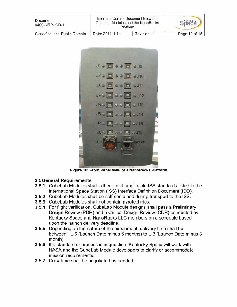
Data downloads from CubeLab Modules installed on a NanoRacks Platform involve an astronaut connecting a USB data cable from the front panel of a NanoRacks Platform (Figure 10) to the ELC. Once connected, the CubeLab Module shall come up as an external drive on the ELC and files will be manually transferred from the CubeLab Module to a dedicated partition on the ELC. A ground controller transfers data from the partition on the ELC to earth through the TDRSS network. From there, data can be disseminated to researchers via a secure internet connection.
Document: 8400-NRP-ICD-1
Interface Control Document Between CubeLab Modules and the NanoRacks
Platform
Classification: Public Domain Date: 2011-1-11 Revision: 1 Page 10 of 15
Figure 10: Front Panel view of a NanoRacks Platform
3.5 General Requirements 3.5.1 CubeLab Modules shall adhere to all applicable ISS standards listed in the
International Space Station (ISS) Interface Definition Document (IDD). 3.5.2 CubeLab Modules shall be self-contained during transport to the ISS. 3.5.3 CubeLab Modules shall not contain pyrotechnics. 3.5.4 For flight verification, CubeLab Module designs shall pass a Preliminary
Design Review (PDR) and a Critical Design Review (CDR) conducted by Kentucky Space and NanoRacks LLC members on a schedule based upon the launch delivery deadline.
3.5.5 Depending on the nature of the experiment, delivery time shall be between: L-6 (Launch Date minus 6 months) to L-3 (Launch Date minus 3 month).
3.5.6 If a standard or process is in question, Kentucky Space will work with NASA and the CubeLab Module developers to clarify or accommodate mission requirements.
3.5.7 Crew time shall be negotiated as needed.
Document: 8400-NRP-ICD-1
Interface Control Document Between CubeLab Modules and the NanoRacks
Platform
Classification: Public Domain Date: 2011-1-11 Revision: 1 Page 11 of 15 3.6 NanoRack Platform Interface 3.6.1 Each CubeLab Module shall be connected to the NanoRack Platform by a
type B female USB connector shown in Figure 7. 3.6.2 USB port location shall be designed to minimize the impact to other
Cubelab Modules. Placement shall be approved during the PDR. 3.6.3 If multiple 1U units are combined (See Table 1), inactive USB ports shall
be “dummy” units, with excess dimensional tolerance to facilitate easy alignment of the CubeLab Module to the NanoRacks Platform.
3.7 Materials 3.7.1 CubeLab Module housing and internals shall be made of materials
approved by NASA for use aboard the ISS. Refer to NASA STD-6016 for detailed requirements. See the CubeLab Module ICD webpage for latest version.
3.7.2 CubeLab Modules shall not contain hazardous materials. If unsure of the classification of a material contact Kentucky Space.
3.7.3 Low offgassing materials shall be used. For a list of offgassing requirements, refer to NASA-STD-(I)-6001A. See the CubeLab Module ICD webpage for the latest version.
3.7.4 CubeLab Modules shall not contain sharp edges that could potentially harm an astronaut on orbit. For testing requirements refer to section 4.4.
3.8 Electrical 3.8.1 Maximum power shall be 2 Watts per USB port at 5VDC. 3.8.2 Data transfer shall be completed through scheduled USB connectivity to
ELC. 3.8.3 CubeLab Modules shall operate nominally during periods of intermittent
power as a result of normal operations aboard the ISS. Should power be cut unexpectedly to the CubeLab Module, a recovery mode shall exist allowing the CubeLab Module to recover and return to normal operations.
3.8.4 USB interface on the CubeLab Module shall be USB type B female receptacle. Refer to Figure 7 for dimensional requirements of the USB type B Female connector. Additional information can be found at the NanoRacks developers website referenced above.
3.9 Operations 3.9.1 Upon being plugged into the NanoRacks Platform, CubeLab Modules will
receive 5V through the USB port. Communication shall only occur when initiated by an astronaut using the data cable to connect the ELC to the corresponding port on the NanoRacks Platform.
3.9.2 CubeLab Modules should be standalone units. Astronaut interaction with a CubeLab Modules should be limited to installation and data collection. More involved crew interaction must be discussed as early as possible with Kentucky Space personnel.
Document: 8400-NRP-ICD-1
Interface Control Document Between CubeLab Modules and the NanoRacks
Platform
Classification: Public Domain Date: 2011-1-11 Revision: 1 Page 12 of 15 3.10 Data Handling 3.10.1 Communication between the CubeLab Module and the ELC shall follow
the USB standard. 3.10.2 CubeLab Modules shall adhere to the Mass Storage Bulk Only subclass
of the Universal Serial Bus Mass Storage Class Specification found here: http://www.usb.org/developers/devclass_docs/usbmassbulk_10.pdf
3.10.3 To verify USB mass storage requirement, tests shall be performed by using the latest Command Verifier utility found here: http://www.usb.org/developers/tools/
3.10.4 Each CubeLab Module shall pass the ‘MSC Test’ suite, part of the Command Verifier utility.
3.10.5 The CubeLab Module/ELC interface shall not require any drivers to be loaded onto the ELC to operate nominally.
3.10.6 The CubeLab Module shall use the USB storage port driver (usbstor.sys) which is included in Microsoft Windows 2000 and later.
3.10.7 The following CubeLab Module activation options can be employed: EXPRESS Rack power application, CubeLab Module manual switch.
3.10.8 Experiment data can be retrieved by: USB file transfer to ELC followed by downlink transmission or downmass return.
3.10.9 Files to be downlinked shall be no larger than 10 Megabytes. 3.10.10 Possible deactivation options: CubeLab Module manual switch
accessible from exterior of CubeLab Module, or removal of CubeLab Module from the USB docking port.
3.10.11 If permitted by mechanical design, it is highly recommended that the internal memory of the CubeLab Module be easily removable through an external interface so the memory can be returned from the ISS.
4.0 Testing Requirements
CubeLab Modules shall meet all requirements listed in this document and shall be verified by the interface designers. Additional testing may be required by NASA on a module by module basis, depending on the nature of the design. All documents mentioned within this section are located at the CubeLab Module ICD webpage under the documents section. http://ssl.engr.uky.edu/cubelab/documents
4.1 Acoustics CubeLab Modules shall adhere to the NASA ISS “HRF Acoustic Noise Control and Analysis Plan”.
4.2 Electromagnetic Interference (EMI)
CubeLab Modules shall adhere to the NASA ISS “HRF Electromagnetic Compatibility Control Plan”.
Document: 8400-NRP-ICD-1
Interface Control Document Between CubeLab Modules and the NanoRacks
Platform
Classification: Public Domain Date: 2011-1-11 Revision: 1 Page 13 of 15 4.3 Offgassing
An offgassing test shall be performed to ensure low offgassing requirements are met, refer to NASA-STD-(I)-6001A.
4.4 Sharp Edge Test
CubeLab Modules shall undergo a cotton glove test to ensure that no protruding or sharp edges exist that could potentially snag the glove as it is passed over all surfaces of the CubeLab Module.
4.5 Depressurization Test
For CubeLab Modules containing volumes of liquid, a pressure vessel, or a biological payload a depressurization/repressurization must be completed. This test stimulates a loss of pressure inside the ISS and demonstrates that the Module maintains fluid containment in this event.
4.6 Additional Requirements
CubeLab Modules shall adhere to all applicable requirements in the Expedite the Processing of Experiments to Space Station (EXPRESS) Rack Payloads Interface Definition Document - SSP 52000-IDD-ERP Revision H. Safety Data Package submissions to NASA will determine which sections are applicable to a module. The follow list is provided for reference to assist developers in the design of a module.
4.6.1 The aforementioned requirements include (but are not limited to) the
following sections: 4.1.1.1/Express Payload Frequency Compatibility 4.7.2/Payload-Generated Acoustic Noise 4.8/DEPRESSURIZATION/REPRESSURIZATION REQUIREMENTS 4.9/GROUND HANDLING ENVIRONMENTS 4.10/MICROGRAVITY DISTURBANCES 5.1.1/EXTERNAL SURFACE TOUCH TEMPERATURE 5.1.2.1/CONDENSATION PREVENTION 5.1.3/LOSS OF COOLING 5.1.4/PRESSURE RELIEF/VENT VALVE SIZING 5.2/ENVIRONMENTAL CONDITIONS 5.3.1/PAYLOAD HEAT DISSIPATION 5.4.9/VACUUM OUTGASSING REQUIREMENTS 7.1/CIRCUIT EMC CLASSIFICATIONS 7.5.1/Electrical Bonding 10.1/PAYLOAD EQUIPMENT SURFACE CLEANLINESS 10.2.1/SPECULARITY 10.3.1/LASERS 10.3.2/NON IONIZING RADIATION 10.3.4/ACCIDENTAL EXPOSURES
Document: 8400-NRP-ICD-1
Interface Control Document Between CubeLab Modules and the NanoRacks
Platform
Classification: Public Domain Date: 2011-1-11 Revision: 1 Page 14 of 15
10.4.1/PAYLOAD CONTAINED OR GENERATED IONIZING RADIATION 10.4.2/SINGLE EVENT EFFECT (SEE) IONIZING RADIATION 10.4.3/RADIATION DOSE REQUIREMENTS 10.5/ATMOSPHERE REQUIREMENTS 10.5.1/OXYGEN CONSUMPTION 10.5.2/HAZARDOUS RELEASES 13.1.1/ACCEPTANCE CRITERIA FOR STRESS CORROSION CRACKING (SCC) 13.1.2/HAZARDOUS MATERIALS AND COMPATIBILITY 13.1.3/TEST AND ACCEPTANCE CRITERIA FOR FLAMMABILITY 13.1.4/TEST AND ACCEPTANCE CRITERIA FOR TOXIC OFFGASSING (TOXICITY) 13.3/FUNGUS RESISTANT MATERIALS 14.1/FIRE EVENT PREVENTION REQUIREMENTS 14.1.1/FLAMMABILITY REQUIREMENTS 14.1.2/OXYGEN 14.1.3/ELECTRICAL SYSTEMS 14.1.4/PAYLOAD USE OF BATTERY BACKUP POWER
Document: 8400-NRP-ICD-1
Interface Control Document Between CubeLab Modules and the NanoRacks
Platform
Classification: Public Domain Date: 2011-1-11 Revision: 1 Page 15 of 15
Appendix A – NanoRack Platform Side Panel Drawing