Interconnection Procedures - pvrea.coop
15
Small Generator Interconnection Procedures and Guidelines www.pvrea.coop 1-800-432-1012 Page 1 of 15 July 2019 Version 2 Procedures The Small Generation Interconnection Procedures and Guidelines shall apply to all small generating facilities connecting with Poudre Valley Rural Electric Association’s (PVREA) system where the total nameplate generating capacity connected at one-meter location is less than ten (10) MW. PVREA’s processes for evaluating interconnection requests are as follows: Level 1 Process – An interconnection request for a Certified inverter-based small generating facility no larger than twenty-five (25) kW or 120% of the twelve-month historical usage at the metering point, whichever is less; Level 2 Process (Fast Track) – An Interconnection request for a Certified small generating facility no larger than two (2) MW; Level 3 Process – An Interconnection request for a small generating facility larger than two (2) MW but no larger than ten (10) MW, a Small generating facility that is not Certified, or a Certified small generating facility that does not pass the Level 1 Process or Level 2 Process. PVREA will following the process described in the Colorado Public Utilities Commission Interconnections Standards and Procedures presently in 4 CCR 723-3-3667 or successors.
Transcript of Interconnection Procedures - pvrea.coop

Small Generator Interconnection Procedures and Guidelines
www.pvrea.coop 1-800-432-1012
Page 1 of 15 July 2019 Version 2
Procedures The Small Generation Interconnection Procedures and Guidelines shall apply to all small generating facilities connecting with Poudre Valley Rural Electric Association’s (PVREA) system where the total nameplate generating capacity connected at one-meter location is less than ten (10) MW.
PVREA’s processes for evaluating interconnection requests are as follows:
Level 1 Process – An interconnection request for a Certified inverter-based small generating facility no larger than twenty-five (25) kW or 120% of the twelve-month historical usage at the metering point, whichever is less;
Level 2 Process (Fast Track) – An Interconnection request for a Certified small generating facility no larger than two (2) MW;
Level 3 Process – An Interconnection request for a small generating facility larger than two (2) MW but no larger than ten (10) MW, a Small generating facility that is not Certified, or a Certified small generating facility that does not pass the Level 1 Process or Level 2 Process.
PVREA will following the process described in the Colorado Public Utilities Commission Interconnections Standards and Procedures presently in 4 CCR 723-3-3667 or successors.
Small Generator Interconnection Procedures and Guidelines
Page 2 of 15
Guidelines Introduction
The purpose of this document is to set forth the requirements of Poudre Valley Rural Electric Association, Inc. (PVREA) regarding interconnection with, purchases from, sales to, and wheeling for qualifying Small Generating Facilities (SGF). A Small Generating Facility is a Qualifying Facility (QF), which is a generating facility which meets the requirements for QF status under the Public Utility Regulatory Policies Act of 1978 (PURPA) and part 292 of the Commission's Regulations (18 C.F.R. Part 292).
PVREA will assist SGF owners with the interconnection of the SGF to PVREA’s power system. SGF owners should initially contact PVREA for basic information regarding interconnection. Detailed interconnection studies and contractual development for SGFs over 25 kW will potentially involve both Tri-State Generation and Transmission Association, PVREA’s wholesale provider, and PVREA.
PVREA will permit interconnection and parallel operation with a SGF in accordance with the terms and conditions set forth in this document and the rules and regulations of the Public Utilities Commission of the State of Colorado (PUC) .
Some of the information contained in this policy statement and attachments is technical in nature. SGF owners should contact PVREA if assistance is needed to understand any such information. Inquiries concerning interconnection of SGF may be directed to:
Contact: Poudre Valley Rural Electric Association, Inc. P.O. Box 272550 7649 REA Parkway Fort Collins, CO 80528 (970) 226-1234
No Warranty
Any inspections, reviews of plans, specifications and/or sites and any approvals, written or oral, are conducted or provided solely for the use and purposes of PVREA; PVREA makes no warranty, direct or indirect, and provides no assurances, direct or indirect, as to the adequacy or safety of any plans, specifications, sites, installations or other characteristics of the SGF. The owners of SGF are solely responsible for determining and ensuring the adequacy and safety of all plans, specifications, sites, installations and other characteristics of the SGF.
Small Generator Interconnection Procedures and Guidelines
Page 3 of 15
Standards for Interconnection and Protection of a Small Generating Facility (SGF)
1.0 Introduction
These standards have been established to assist SGF owners in planning and designing an electrical interconnection with the system of PVREA and Tri-State. The SGF and PVREA personnel may be guided by this document when planning, installing, and operating the SGF. The following requirements are general in nature and may not cover all details of a specific installation. Potential SGF owners should discuss project plans with PVREA before purchasing or installing equipment.
2.0 General Requirements For Interconnection
Certain protective equipment (relays, circuit breakers, etc.) and other apparatus specified by PVREA must be installed at locations where the SGF owner wishes to operate generating facilities in parallel with PVREA’s system. The purpose of this equipment is to ensure safe and reliable power system operation and to allow prompt disconnection of the SGF in the event of short circuit or other malfunction. Other changes, such as revisions to the electrical system configuration and/or modifications to protective equipment at other locations, may also be required in order to accommodate parallel operation. PVREA will assist SGF owners in determining interconnection requirements. This document gives general information about parallel operation; however, PVREA may impose additional restrictions or require additional equipment when the particular installation so warrants. Each SGF must be reviewed individually, since interconnection requirements vary with the type of generation equipment and the proposed location on PVREA’s system. All costs associated with interconnection, necessary system additions, and modifications to accommodate the SGF will be borne by the SGF owner.
PVREA requires that the SGF owner design, construct and operate their equipment in a manner which will not degrade the quality of service to other PVREA consumers. This requires that the SGF equipment be designed, specified and installed in a manner appropriate to its intended service and in accordance with all applicable standards regulating design, construction and operation of such equipment. PVREA reserves the right to specify the quality and determine the adequacy of SGF owner equipment, installation and operation in any respect which affects safety, reliability or quality of service.
PVREA will not assume responsibility for protection of the generator(s) or any other portion of the SGF owners electrical equipment. The SGF is fully responsible for properly protecting its equipment. Equipment which is not properly protected may be damaged as the result of normal system operation or disturbances on PVREA’s system. PVREA will, however, aid the SGF in determining conditions to which its equipment is likely to be subjected as a result of probable system operation, malfunctions or disturbances, insofar as it is possible to determine these conditions in advance.
A permanent, weather proof sign indicating the location of the SGF Generation Disconnect shall be clearly displayed at the point of service connection (generally at the interconnection meter). For SGFs with a capacity greater than 25 kW (Alternating Current) for commercial accounts and 25 kW (direct Current) for residential accounts, a one-line electrical diagram and the names and current telephone numbers of at least two persons that are authorized to provide access to the SGF and who have authority to make decisions regarding the SGF interconnection and operation shall be included with or attached to the sign. This telephone listing shall be updated as needed to maintain its usefulness.
2.1 Codes, Standards and Regulatory Agencies
Small Generator Interconnection Procedures and Guidelines
Page 4 of 15
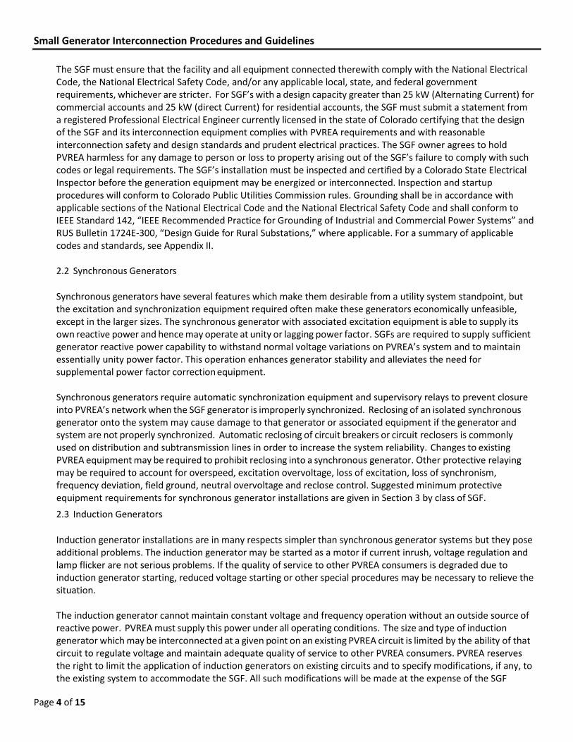
The SGF must ensure that the facility and all equipment connected therewith comply with the National Electrical Code, the National Electrical Safety Code, and/or any applicable local, state, and federal government requirements, whichever are stricter. For SGF’s with a design capacity greater than 25 kW (Alternating Current) for commercial accounts and 25 kW (direct Current) for residential accounts, the SGF must submit a statement from a registered Professional Electrical Engineer currently licensed in the state of Colorado certifying that the design of the SGF and its interconnection equipment complies with PVREA requirements and with reasonable interconnection safety and design standards and prudent electrical practices. The SGF owner agrees to hold PVREA harmless for any damage to person or loss to property arising out of the SGF’s failure to comply with such codes or legal requirements. The SGF’s installation must be inspected and certified by a Colorado State Electrical Inspector before the generation equipment may be energized or interconnected. Inspection and startup procedures will conform to Colorado Public Utilities Commission rules. Grounding shall be in accordance with applicable sections of the National Electrical Code and the National Electrical Safety Code and shall conform to IEEE Standard 142, “IEEE Recommended Practice for Grounding of Industrial and Commercial Power Systems” and RUS Bulletin 1724E-300, “Design Guide for Rural Substations,” where applicable. For a summary of applicable codes and standards, see Appendix II.
2.2 Synchronous Generators
Synchronous generators have several features which make them desirable from a utility system standpoint, but the excitation and synchronization equipment required often make these generators economically unfeasible, except in the larger sizes. The synchronous generator with associated excitation equipment is able to supply its own reactive power and hence may operate at unity or lagging power factor. SGFs are required to supply sufficient generator reactive power capability to withstand normal voltage variations on PVREA’s system and to maintain essentially unity power factor. This operation enhances generator stability and alleviates the need for supplemental power factor correction equipment.
Synchronous generators require automatic synchronization equipment and supervisory relays to prevent closure into PVREA’s network when the SGF generator is improperly synchronized. Reclosing of an isolated synchronous generator onto the system may cause damage to that generator or associated equipment if the generator and system are not properly synchronized. Automatic reclosing of circuit breakers or circuit reclosers is commonly used on distribution and subtransmission lines in order to increase the system reliability. Changes to existing PVREA equipment may be required to prohibit reclosing into a synchronous generator. Other protective relaying may be required to account for overspeed, excitation overvoltage, loss of excitation, loss of synchronism, frequency deviation, field ground, neutral overvoltage and reclose control. Suggested minimum protective equipment requirements for synchronous generator installations are given in Section 3 by class of SGF.
2.3 Induction Generators
Induction generator installations are in many respects simpler than synchronous generator systems but they pose additional problems. The induction generator may be started as a motor if current inrush, voltage regulation and lamp flicker are not serious problems. If the quality of service to other PVREA consumers is degraded due to induction generator starting, reduced voltage starting or other special procedures may be necessary to relieve the situation.
The induction generator cannot maintain constant voltage and frequency operation without an outside source of reactive power. PVREA must supply this power under all operating conditions. The size and type of induction generator which may be interconnected at a given point on an existing PVREA circuit is limited by the ability of that circuit to regulate voltage and maintain adequate quality of service to other PVREA consumers. PVREA reserves the right to limit the application of induction generators on existing circuits and to specify modifications, if any, to the existing system to accommodate the SGF. All such modifications will be made at the expense of the SGF

Small Generator Interconnection Procedures and Guidelines
Page 5 of 15
owner.
Capacitors installed at the generator may be required to limit the adverse effects of excess VAR flow on PVREA’s system. Installation of capacitors at or near an induction generator increases the risk that the machine may become self-excited if it is completely isolated from or isolated with a relatively small portion of PVREA’s system. A self-excited induction generator can produce power of abnormal voltage and frequency. This unregulated power may damage equipment of other consumers who are electrically connected to the isolated generator.
To minimize the risk of self-excited operation, the compensation installed at or near an induction generator should be limited to that value necessary to correct the no-load power factor to 95 percent. Over and under-frequency relays and voltage regulation relays will also be required on all induction generators to protect against self-excited operation. Other protective equipment such as voltage restrained overcurrent relays may be required to reduce the possibility of damage to PVREA equipment or the equipment of other consumers. Where self-excitation problems appear likely, it may be necessary to rearrange the distribution network to avoid isolating the induction generator with a small attached load. Costs of power factor correction equipment, protective equipment and any PVREA system changes must be borne by the SGF owner.
Reclosing of a distribution line after a utility system disturbance may cause damage to the SGF owner’s induction generator if adequate protective equipment is not installed to mitigate the adverse effects.
2.4 Inverter Systems
Inverter systems are used to transform direct current to alternating current. The resulting waveform may be rich in harmonics. These nonstandard waveforms may cause radio and television interference on other consumers equipment, objectionable audible noise, and malfunction of electrical equipment. Excessive harmonic content may also cause overheating in electrical equipment.
The inverter system should be designed and operated in accordance with UL 1741 and IEEE 1547. This standard (“Inverters, Converters, and Controllers for Use in Independent Power Systems”) addresses the electrical interconnection design of various forms of generating equipment. Many manufacturers submit their equipment to a Nationally Recognized Testing Laboratory (NRTL) that verifies compliance with UL 1741. This “listing” is then marked on the equipment and supporting documentation.
All three-phase inverter installations shall be served by a dedicated transformer which is connected delta on the generator side and wye on PVREA’s side. The type of high side grounding, if any, will be determined by PVREA. The cost of this transformer and associated equipment shall be borne by the SGF owner.
Inverter systems require a significant reactive power flow to ensure proper operation. PVREA requires the SGF owner to provide equipment to correct the power factor. However, care must be taken to ensure that an inverter system which is electrically close to capacitors cannot drive an isolated load. Self- commutated inverters as well as line-commutated inverters connected to rotating machines may operate in a self-excited mode. In order to protect PVREA’s equipment and other consumers equipment, the SGF shall install protective relays to prevent isolated operation. For the purpose of preventing service to isolated loads, inverter systems shall conform to standards outlined in IEEE Standard 929.
2.5 Protection Of The Utility System
In order to be assured of continuing safe, reliable service to PVREA consumers, PVREA must be concerned with the manner in which SGF are connected to the existing PVREA system. PVREA’s concerns are fourfold:
1) The SGF must promptly disconnect from PVREA in the event of a utility system disturbance;

Small Generator Interconnection Procedures and Guidelines
Page 6 of 15
2) The SGF must disconnect in the event of a malfunction or disturbance on the SGF equipment; 3) The SGF must not backfeed a de-energized PVREA line; and 4) The SGF must not significantly degrade the quality of service to other PVREA consumers.
2.5.1 Utility System Disturbances
In the event of a utility line fault or other system disturbance, protective equipment will promptly act to de-energize the affected line section. A SGF connected to this portion of line represents an additional source of power to energize the line. Thus, the SGF’s equipment must also automatically act to disconnect the generator(s) to avoid contributing to the severity of the fault, to avoid isolated operation and to protect the SGF equipment.
Isolated operation occurs when a portion of the PVREA load becomes separated from the PVREA source but is still connected to the parallel generation. If the isolated load is sufficiently large with respect to the rated output of the SGF, the voltage will collapse and protective relays will take the machines off line. When the generator rating is greater than or comparable to the size of the isolated load, sustained independent operation becomes possible. This situation is intolerable, since the voltage and frequency on the isolated network are likely to be poorly regulated and damage to PVREA equipment, or that of other consumers, is likely to result. Restoration of normal service to this island is also hampered by the presence of an isolated energy source.
In instances where PVREA’s system arrangement is such that it is possible that the generators will not always be isolated with a sufficiently large load to prevent independent operation, PVREA requires the installation of voltage and frequency relays, even on the smallest SGFs. For installations with rated capacity of greater than 25 kW (Alternating Current) for commercial accounts and 25 kW (Direct Current) for residential accounts, specific devices are required to detect faults on PVREA’s system as well as voltage and frequency relays to detect isolated operation. Equipment may also be required on PVREA’s system to provide additional assurance that islanded operation does not continue. The need for such equipment will be determined on a case-by-case basis.
2.5.2 SGF Disturbances
To prevent loss of service to other PVREA consumers, the SGF must provide protective equipment to promptly disconnect their generators in the event of a fault or other disturbance on the SGF’s installation. The protective equipment must be coordinated with PVREA’s equipment to ensure proper operation in the event of a fault. PVREA will assist the SGF to properly coordinate the protective equipment.
2.5.3 Backfeed To Utility System
The distributed generators provide an additional source of power for PVREA’s network. The SGF must provide protective equipment sufficient to give positive assurance that the generators cannot be connected to an otherwise de-energized PVREA line. This prevents a potential hazard to PVREA personnel who may be in contact with the line for maintenance purposes. In addition to an automatic fail-safe device, PVREA will require an accessible disconnect device that is visibly marked “Generation Disconnect” and has the capability of isolating the energy generated by each SGF. This device must be lockable in the open position and may be operated by either party at any time in order to maintain safe operating conditions. At a minimum, this protection can be provided by an isolation switch which can be locked in the open position by PVREA to visibly indicate isolation of the SGF. Other equipment such as undervoltage, synchronizing, voltage phase sequence or reclosing relays may also be required.
If it is discovered that any equipment connected to the PVREA system is in PVREA’s judgement problematic or

Small Generator Interconnection Procedures and Guidelines
Page 7 of 15
is considered to be unsafe it will be disconnected immediately from the PVREA system.
2.5.4 Power Quality
The SGF will not be allowed to degrade the quality of power delivered to other PVREA consumers. The SGF will be expected to operate within the limits on voltage, frequency and harmonic content as outlined in Appendix II.
The SGF synchronous generation is expected to operate at as nearly unity power factor as is practical to prevent voltage flicker upon switching. The generator and associated equipment are expected to be engineered to allow stable unity power factor operation without exceeding the voltage regulation limits outlined in RUS Bulletin 169-4, “Voltage Levels.” Power factor limits on SGF induction generators are discussed in Section 2.3. Should voltage regulation or lamp flicker become a problem, then operational restrictions may be imposed until the situation can be corrected.
Excess harmonic content or unnecessary service interruptions will not be allowed. If degradation in quality of service to other PVREA consumers or interference with the operation of PVREA equipment occurs, PVREA will disconnect the SGF generators until such time as the problem is resolved.
2.5.5 Protective Equipment
The type and quality of protective equipment required will depend on the size and type of the AF generation equipment as well as the electrical characteristics of PVREA’s interconnection. At a minimum, this equipment will consist of a circuit breaker with associated relaying, a disconnect switch, and voltage and frequency regulation relays. Additional equipment may be necessary for a given installation. The equipment specified above may be part of a vendor-supplied control package, providing the desired level of protection is ensured. Any such protective equipment must be approved by PVREA for each application. PVREA shall be the only judge of adequacy and suitability of protective equipment for SGF installations.
2.6 Protection of SGF Facilities
The SGF is solely responsible for protection of its equipment. To facilitate its design, PVREA herein lists potential hazards to the SGF equipment which might occur as a result of interconnection with PVREA’s system. The probable hazards are of three types: those that occur as a direct result of a faulted transmission or distribution line, synchronism problems, and voltage surges.
Transmission and distribution lines are susceptible to both short circuits and ground faults. Both of these line faults may produce excessive phase currents, single-phased supply and excessive negative sequence currents. Typical equipment to sense and protect against these hazards are listed in Section 3.
The SGF unit can be damaged by interconnection with PVREA’s system if the voltage, phase sequence or phase angle of the machine does not match that of the system. For synchronous generators the SGF owner must provide either automatic synchronizing equipment or a synchronizing relay to supervise manual closure. Unsupervised manual synchronizing is not permitted. Induction starting will be allowed if the inrush current is not excessive. Should voltage dip or lamp flicker problems result from induction starting, other steps must be taken to eliminate these problems. Damage may result to a SGF unit as a result of automatic reclosing unless proper protection is provided. PVREA’s transmission and distribution lines are usually equipped with circuit reclosers which, after a time delay, attempt to restore a circuit which has been tripped due to a fault. If the fault was temporary, the recloser is successful and the circuit is restored to service; if not, the circuit is locked out until manual reclosing is attempted. The recloser may attempt to restore the circuit several times before lockout occurs. If the SGF unit was not taken off-line when PVREA’s circuit was opened, the generator and PVREA’s system may

Small Generator Interconnection Procedures and Guidelines
Page 8 of 15
not reclose in synchronism. Voltage surges and damaging torque may occur upon reclosing. Protective devices should be installed to trip the generator before reclosing is attempted and to prohibit reclosing into PVREA’s system if PVREA’s voltage is of abnormal magnitude or phase sequence. Modifications to PVREA’s recloser or addition of other equipment may be required to protect the SGF unit. The cost of such modifications will be charged to the SGF.
Transient voltage surges may occur on PVREA lines due to switching operations or lightning strikes. The SGF should have protective devices to mitigate the effects of these surges as well as direct lightning strikes. Inverter systems and other solid state components are particularly susceptible to damage by voltage surge.
Details of typical protective equipment to sense and mitigate the potential hazards described above are given in Section 3.
2.7 Inspection And Maintenance
The SGF shall not commence interconnected operation, until:
1) The SGF has supplied PVREA with a completed Application for Interconnection on a form supplied by
PVREA for review and acceptance. 2) The SGF has obtained a certificate of code compliance from a Colorado State Electrical Inspector; 3) PVREA has made any necessary modifications to its system to accommodate the SGF; 4) PVREA has inspected and observed testing of the SGF and certified, in writing, that the SGF has complied
with all requirements for interconnection; and 5) The SGF has submitted proof of adequate insurance.
The completed installation will be subject to a final inspection and test by PVREA for compliance before parallel operation is permitted. PVREA will determine satisfactory performance.
The SGF must notify PVREA prior to any modifications made to the SGF system or to the interconnection between the SGF and PVREA. The SGF must receive approval from PVREA prior to proceeding with such modifications. The SGF must permit PVREA, at any time, to install or modify any equipment, facility, or apparatus to protect the safety of its employees and insure the accuracy of its metering equipment. These costs will be borne by the SGF owner.
The SGF must permit PVREA employees to enter its property at any time for the purpose of inspecting and/or testing the interconnection facilities to ensure their continued safe operation and the accuracy of PVREA’s metering equipment, but such inspection does not relieve the SGF owner of the obligation to maintain the facilities in satisfactory operating condition.
The SGF shall discontinue parallel operations when requested by PVREA:
1) To facilitate maintenance, test or repair of utility facilities; 2) During system emergencies; 3) When the SGF equipment is interfering with other consumers on the system; 4) When an inspection of the SGF reveals a condition likely to be hazardous to PVREA’s system; and 5) When an inspection of the SGF facility reveals that the generating equipment is operating outside
allowable limits on voltage, frequency, power factor or harmonic content. The SGF shall operate and maintain the interconnection equipment at its cost unless previous arrangements have been made with PVREA to maintain the interconnection. In this case, PVREA will operate and maintain the interconnection and bill the SGF for these services.
In all other respects, inspection and maintenance of the SGF shall conform to applicable Colorado Public Utilities

Small Generator Interconnection Procedures and Guidelines
Page 9 of 15
Commission regulations.
2.8 Important Considerations For Interconnection
The SGF owner should allow adequate time in the design and construction schedule for design interface meetings with PVREA and for material procurement by PVREA. This time will vary depending on the SGF’s location, size, design, specific operating and system requirements, and the availability of materials needed to accomplish the interconnection.
If it is discovered that any equipment connected to the PVREA system is in PVREA’s judgement problematic or is considered to be unsafe it will be disconnected from the PVREA system.
SGF’s that generate electrical energy for on-site use only and are interlocked or otherwise prevented from feeding energy into the PVREA system are special cases and may not be required to meet all of the requirements of this document. However, they are required to show by design and by operation that they cannot feed energy into the PVREA system.
3.0 Specific Requirements for Interconnection
PVREA has established guidelines for the protection and interconnection of parallel generators by size classes. These guidelines represent the minimum requirements for interconnection and recommended practice for SGF equipment protection. The SGF owner shall be the sole judge of what equipment is necessary to protect the SGF units and associated electrical equipment. PVREA shall be the sole judge of what equipment is necessary to ensure a safe, reliable interconnection with PVREA’s system.
The size classes for parallel distributed generation are:
1) 25 kW and below; 2) Greater than 25 kW;
3.1 Distributed Generation Less Than Or Equal To 25 kW
SGF with less than or equal to 25 kW in capacity is covered by PVREA Net Metering regulations.
3.2 Distributed Generation Greater Than 25 kW
SGF with greater than 25 kW in capacity will be studied on a case-by-case basis by PVREA and Tri-State to determine specific requirements. Typical protective devices are listed below and typical facilities are shown in DG-W100.
3.3 Typical Protective Device Descriptions
Device Numbers for Protective Equipment
13 – Speed Switch
15 – Tachometer Relay
25 – Synchronizing Relay
27 – Undervoltage Relay

Small Generator Interconnection Procedures and Guidelines
Page 10 of 15
32 – Directional Power Relay
38 – Bearing Temperature
40 – Generator Field Failure Relay
46 – Phase-Balance (Reverse-Phase) Current Relay 47 – Phase-Sequence Voltage Relay
49 – Thermal Relay
49T – Transformer Thermal Relay
49G – Generator Thermal Relay 51 – Time-Overcurrent Relay
51GB - Ground Bank Time-Overcurrent
51T - Transformer Time-Overcurrent
51V - Voltage-Restrained Time-Overcurrent or Voltage-Controlled Time-Overcurrent
52 - Circuit Breaker (52G - Generator Circuit Breaker)
59 - Overvoltage
64G - Ground Detector Relay
67 - Directional Overcurrent
81 - Frequency Relay (over-frequency & under-frequency)
87 - Differential Relay
87G - Generator Differential
87T - Transformer Differential
90 - Field Voltage Regulator S.A./L.A. - Surge Arrestor
3.4 Overview of Technical Requirements of Interconnection and Operation of SGF Resources
The SGF installation must meet all applicable national, state, and local construction and safety codes as well as
all requirements of PVREA and Tri-State.
The SGF installation must be equipped with protective hardware and software designed to prevent the generator from being connected to a de-energized circuit owned by PVREA. The SGF installation shall not energize the point of common coupling when the PVREA system has been de-energized.
The SGF installation must be equipped with protective hardware and software designed to prevent the
connection or parallel operation of the SGF installation with the PVREA system unless the PVREA system service voltage and frequency is of nominal value.
The SGF installation shall not degrade the voltage provided to other PVREA members to service voltages outside
the limits of ANSI C84.1, Range A.
The PVREA distribution system is a four wire multi-grounded neutral system. All grounding must ensure that fault conditions are not worsened by the interconnection of the SGF installation including not overly de-
Small Generator Interconnection Procedures and Guidelines
Page 11 of 15
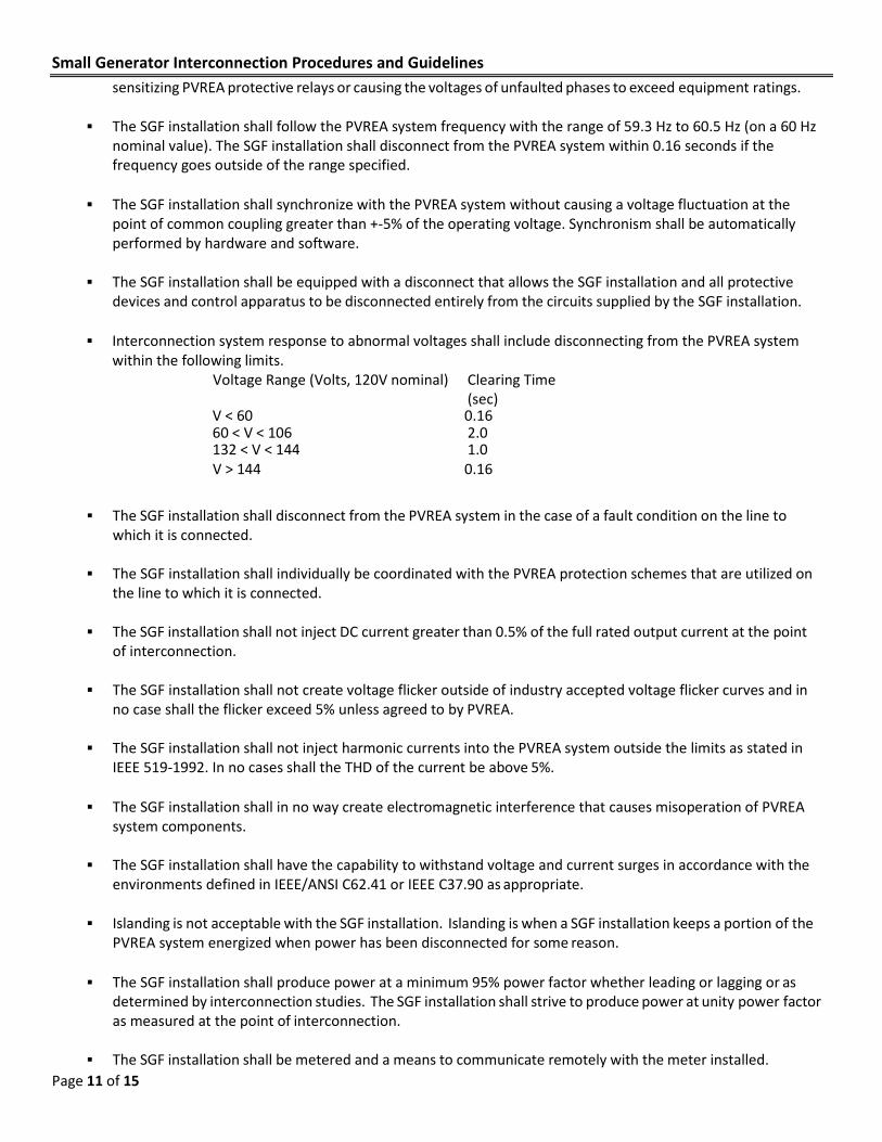
sensitizing PVREA protective relays or causing the voltages of unfaulted phases to exceed equipment ratings.
The SGF installation shall follow the PVREA system frequency with the range of 59.3 Hz to 60.5 Hz (on a 60 Hz nominal value). The SGF installation shall disconnect from the PVREA system within 0.16 seconds if the frequency goes outside of the range specified.
The SGF installation shall synchronize with the PVREA system without causing a voltage fluctuation at the
point of common coupling greater than +-5% of the operating voltage. Synchronism shall be automatically performed by hardware and software.
The SGF installation shall be equipped with a disconnect that allows the SGF installation and all protective
devices and control apparatus to be disconnected entirely from the circuits supplied by the SGF installation.
Interconnection system response to abnormal voltages shall include disconnecting from the PVREA system within the following limits.
Voltage Range (Volts, 120V nominal) Clearing Time (sec)
V < 60 0.16 60 < V < 106 2.0 132 < V < 144 1.0 V > 144 0.16
The SGF installation shall disconnect from the PVREA system in the case of a fault condition on the line to which it is connected.
The SGF installation shall individually be coordinated with the PVREA protection schemes that are utilized on
the line to which it is connected.
The SGF installation shall not inject DC current greater than 0.5% of the full rated output current at the point of interconnection.
The SGF installation shall not create voltage flicker outside of industry accepted voltage flicker curves and in
no case shall the flicker exceed 5% unless agreed to by PVREA.
The SGF installation shall not inject harmonic currents into the PVREA system outside the limits as stated in IEEE 519-1992. In no cases shall the THD of the current be above 5%.
The SGF installation shall in no way create electromagnetic interference that causes misoperation of PVREA
system components.
The SGF installation shall have the capability to withstand voltage and current surges in accordance with the environments defined in IEEE/ANSI C62.41 or IEEE C37.90 as appropriate.
Islanding is not acceptable with the SGF installation. Islanding is when a SGF installation keeps a portion of the
PVREA system energized when power has been disconnected for some reason.
The SGF installation shall produce power at a minimum 95% power factor whether leading or lagging or as determined by interconnection studies. The SGF installation shall strive to produce power at unity power factor as measured at the point of interconnection.
The SGF installation shall be metered and a means to communicate remotely with the meter installed.

Small Generator Interconnection Procedures and Guidelines
Page 12 of 15
Appendix I – Summary of Interconnection Procedure
1) SGF owner with potential SGF Facility contacts PVREA and obtains Application for Interconnection (Application).
2) The SGF submits the Application to PVREA. If SGF’s nameplate capacity is greater than 25 kW, the Qualifying
Facility Design Data Requirements shown in Appendix III are also required.
3) PVREA evaluates the Application for Interconnection for completeness and notifies the SGF owner within ten business days of receipt that the Application is or is not complete and, if not, advises what material is missing.
4) Within 15 business days, PVREA conducts preliminary engineering studies, if warranted, to determine the
effect the SGF might have on existing PVREA consumers and equipment.
5) Provided all the criteria in the Interconnection Standards for Distributed Generation are met, unless PVREA determines and demonstrates that the SGF cannot be interconnected safely and reliably, PVREA approves and executes the Application and returns it to the SGF owner.
6) PVREA designs and constructs the interconnection and modifies the existing PVREA network as necessary to
accept the SGF.
7) The SGF owner provides notice of insurance coverage. The SGF owner should investigate liability insurance coverage early in the planning stage.
8) After installation, the SGF owner returns the Certificate of Completion to PVREA. Prior to parallel operation,
PVREA will inspect the SGF facility for compliance with standards within ten business days of the receipt of the Certificate of Completion. PVREA will inspect the SGF for compliance with standards, and may schedule appropriate metering replacement, if necessary.
9) PVREA notifies the SGF owner in writing or by fax or e-mail that interconnection of the SGF is authorized within
five business days. If the witness test is not satisfactory, PVREA has the right to disconnect the SGF. The SGF owner has no right to operate in parallel until a witness test has been performed.
10) Interconnection and startup.
Small Generator Interconnection Procedures and Guidelines
Page 13 of 15
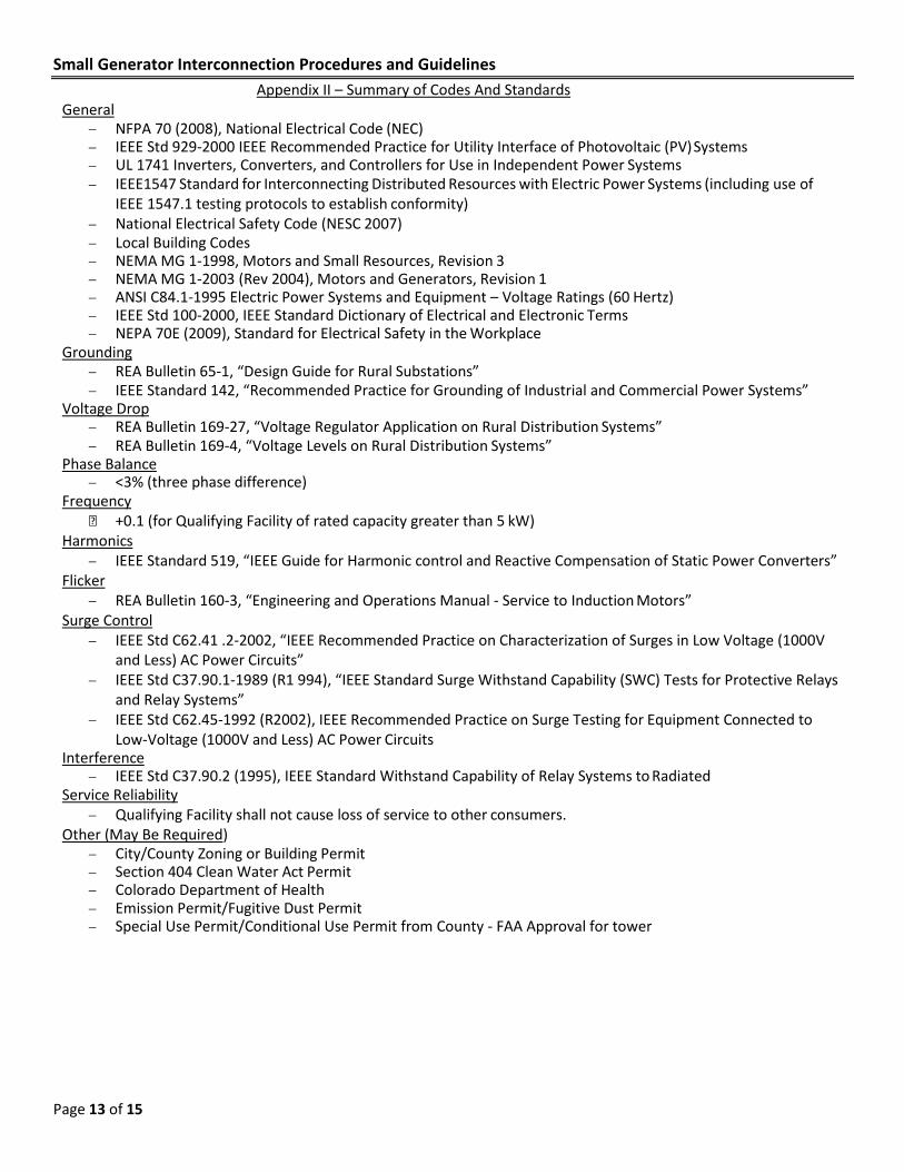
Appendix II – Summary of Codes And Standards General
− NFPA 70 (2008), National Electrical Code (NEC) − IEEE Std 929-2000 IEEE Recommended Practice for Utility Interface of Photovoltaic (PV) Systems − UL 1741 Inverters, Converters, and Controllers for Use in Independent Power Systems − IEEE1547 Standard for Interconnecting Distributed Resources with Electric Power Systems (including use of
IEEE 1547.1 testing protocols to establish conformity) − National Electrical Safety Code (NESC 2007) − Local Building Codes − NEMA MG 1-1998, Motors and Small Resources, Revision 3 − NEMA MG 1-2003 (Rev 2004), Motors and Generators, Revision 1 − ANSI C84.1-1995 Electric Power Systems and Equipment – Voltage Ratings (60 Hertz) − IEEE Std 100-2000, IEEE Standard Dictionary of Electrical and Electronic Terms − NEPA 70E (2009), Standard for Electrical Safety in the Workplace
Grounding − REA Bulletin 65-1, “Design Guide for Rural Substations” − IEEE Standard 142, “Recommended Practice for Grounding of Industrial and Commercial Power Systems”
Voltage Drop − REA Bulletin 169-27, “Voltage Regulator Application on Rural Distribution Systems” − REA Bulletin 169-4, “Voltage Levels on Rural Distribution Systems”
Phase Balance − <3% (three phase difference)
Frequency +0.1 (for Qualifying Facility of rated capacity greater than 5 kW)
Harmonics − IEEE Standard 519, “IEEE Guide for Harmonic control and Reactive Compensation of Static Power Converters”
Flicker − REA Bulletin 160-3, “Engineering and Operations Manual - Service to Induction Motors”
Surge Control − IEEE Std C62.41 .2-2002, “IEEE Recommended Practice on Characterization of Surges in Low Voltage (1000V
and Less) AC Power Circuits” − IEEE Std C37.90.1-1989 (R1 994), “IEEE Standard Surge Withstand Capability (SWC) Tests for Protective Relays
and Relay Systems” − IEEE Std C62.45-1992 (R2002), IEEE Recommended Practice on Surge Testing for Equipment Connected to
Low-Voltage (1000V and Less) AC Power Circuits Interference
− IEEE Std C37.90.2 (1995), IEEE Standard Withstand Capability of Relay Systems to Radiated Service Reliability
− Qualifying Facility shall not cause loss of service to other consumers. Other (May Be Required)
− City/County Zoning or Building Permit − Section 404 Clean Water Act Permit − Colorado Department of Health − Emission Permit/Fugitive Dust Permit − Special Use Permit/Conditional Use Permit from County - FAA Approval for tower

Small Generator Interconnection Procedures and Guidelines
Page 14 of 15
Appendix III – Distributed Generation Design Data Requirements
Poudre Valley Rural Electric Association, Inc. (PVREA) reviews all proposals for interconnection of a SGF facility for compliance with PVREA guidelines and Colorado Public Utilities Commission Rules. PVREA attempts, insofar as is reasonable, to determine whether a design will create problems on PVREA’s system but cannot comment or make assurances on the technical prudence or economic feasibility of a proposed project.
PVREA cannot review your facility design until a complete design package is submitted. Typically, a complete design package would include:
1) A complete site plan, detailing physical locations of all equipment to be installed from PVREA’s supply line to the powerhouse. This plan should show sufficient detail to determine physical clearances between pieces of equipment and between any piece of equipment and an adjacent permanent structure. The site plan should show the location of proposed metering, disconnecting and circuit protective devices. Particular detail should be given to physical location of equipment in the powerhouse, and provisions for grounding of powerhouse equipment.
2) A system one-line diagram which states wire sizes and types, as well as ratings and types of circuit protective devices. This diagram should include all equipment, including transformers which will be installed up to PVREA’s connection.
3) A relay control diagram which clearly indicates relay contact arrangements and which indicates functionally the operation of all relays, protective devices and interlocks.
4) Device types, sizes, model numbers, settings and manufacturer’s data on all circuit protective devices and relays.
5) The location, ratings, impedances, time constants and manufacturer’s data for the generator and all associated control equipment, including but not limited to inverters, lines, exciters, governors, voltage regulators and synchronizers, where applicable.
6) The location, ratings and switching arrangement for power factor correction capacitors, if any. 7) Proposed operating procedures for startup, shutdown and restart functions. The procedures should include
all operational parameters and appropriate limits of operation. 8) Anticipated peak power production and monthly energy production figures.
PVREA recommends not purchasing equipment or beginning construction of facilities until a design review is completed and PVREA gives final written design approval.
[REMAINDER OF PAGE LEFT BLANK INTENTIONALLY]

Small Generator Interconnection Procedures and Guidelines
Page 15 of 15


![pro forma Large Generator Interconnection Procedures[Docket No. RM17-8-000; Order No. 845] Reform of Generator Interconnection Procedures and Agreements (Issued April 19, 2018) AGENCY:](https://static.fdocuments.in/doc/165x107/60b071af9e197848be584075/pro-forma-large-generator-interconnection-procedures-docket-no-rm17-8-000-order.jpg)