
Handbook for Working with Culturally Diverse Geographically Dispersed Teams

Americas HeadquartersCisco Systems, Inc.170 West Tasman DriveSan Jose, CA 95134-1706 USAhttp://www.cisco.comTel: 408 526-4000
800 553-NETS (6387)Fax: 408 527-0883
Interconnecting Geographically Dispersed Data Centers Using VPLSDesign and System Assurance Guide
Text Part Number: OL-20161-01

NOTICE. ALL STATEMENTS, INFORMATION, AND RECOMMENDATIONS IN THIS MANUAL ARE BELIEVED TO BE ACCURATE BUT ARE PRESENTED WITHOUT WARRANTY OF ANY KIND, EXPRESS OR IMPLIED. USERS MUST TAKE FULL RESPONSIBILITY FOR THEIR APPLICATION OF ANY PRODUCTS.
THE SOFTWARE LICENSE AND LIMITED WARRANTY FOR THE ACCOMPANYING PRODUCT ARE SET FORTH IN THE INFORMATION PACKET THAT SHIPPED WITH THE PRODUCT AND ARE INCORPORATED HEREIN BY THIS REFERENCE. IF YOU ARE UNABLE TO LOCATE THE SOFTWARE LICENSE OR LIMITED WARRANTY, CONTACT YOUR CISCO REPRESENTATIVE FOR A COPY.
The Cisco implementation of TCP header compression is an adaptation of a program developed by the University of California, Berkeley (UCB) as part of UCB’s public domain version of the UNIX operating system. All rights reserved. Copyright © 1981, Regents of the University of California.
NOTWITHSTANDING ANY OTHER WARRANTY HEREIN, ALL DOCUMENT FILES AND SOFTWARE OF THESE SUPPLIERS ARE PROVIDED “AS IS” WITH ALL FAULTS. CISCO AND THE ABOVE-NAMED SUPPLIERS DISCLAIM ALL WARRANTIES, EXPRESSED OR IMPLIED, INCLUDING, WITHOUT LIMITATION, THOSE OF MERCHANTABILITY, FITNESS FOR A PARTICULAR PURPOSE AND NONINFRINGEMENT OR ARISING FROM A COURSE OF DEALING, USAGE, OR TRADE PRACTICE.
IN NO EVENT SHALL CISCO OR ITS SUPPLIERS BE LIABLE FOR ANY INDIRECT, SPECIAL, CONSEQUENTIAL, OR INCIDENTAL DAMAGES, INCLUDING, WITHOUT LIMITATION, LOST PROFITS OR LOSS OR DAMAGE TO DATA ARISING OUT OF THE USE OR INABILITY TO USE THIS MANUAL, EVEN IF CISCO OR ITS SUPPLIERS HAVE BEEN ADVISED OF THE POSSIBILITY OF SUCH DAMAGES.
CCDE, CCENT, CCSI, Cisco Eos, Cisco HealthPresence, Cisco IronPort, the Cisco logo, Cisco Lumin, Cisco Nexus, Cisco Nurse Connect, Cisco StackPower, Cisco StadiumVision, Cisco TelePresence, Cisco Unified Computing System, Cisco WebEx, DCE, Flip Channels, Flip for Good, Flip Mino, Flip Video, Flip Video (Design), Flipshare (Design), Flip Ultra, and Welcome to the Human Network are trademarks; Changing the Way We Work, Live, Play, and Learn, Cisco Store, and Flip Gift Card are service marks; and Access Registrar, Aironet, AsyncOS, Bringing the Meeting To You, Catalyst, CCDA, CCDP, CCIE, CCIP, CCNA, CCNP, CCSP, CCVP, Cisco, the Cisco Certified Internetwork Expert logo, Cisco IOS, Cisco Press, Cisco Systems, Cisco Systems Capital, the Cisco Systems logo, Cisco Unity, Collaboration Without Limitation, EtherFast, EtherSwitch, Event Center, Fast Step, Follow Me Browsing, FormShare, GigaDrive, HomeLink, Internet Quotient, IOS, iPhone, iQuick Study, IronPort, the IronPort logo, LightStream, Linksys, MediaTone, MeetingPlace, MeetingPlace Chime Sound, MGX, Networkers, Networking Academy, Network Registrar, PCNow, PIX, PowerPanels, ProConnect, ScriptShare, SenderBase, SMARTnet, Spectrum Expert, StackWise, The Fastest Way to Increase Your Internet Quotient, TransPath, WebEx, and the WebEx logo are registered trademarks of Cisco Systems, Inc. and/or its affiliates in the United States and certain other countries.
All other trademarks mentioned in this document or website are the property of their respective owners. The use of the word partner does not imply a partnership relationship between Cisco and any other company. (0907R)
Interconnecting Geographically Dispersed Data Centers Using VPLS—Design and System Assurance Guide Copyright © 2009 Cisco Systems, Inc. All rights reserved.

Interconnecting GeographicOL-20161-01
C O N T E N T S
Preface 1-v
C H A P T E R 1 Executive Summary 1-1
Cisco Validated Design Program 1-1
Cisco Validated Design 1-1
CVD System Assurance 1-2
C H A P T E R 2 Data Center Interconnect: Legacy Deployment Models and Problems Associated with Extended L2 Networks 2-1
Legacy Deployment Models for Data Center Interconnect 2-1
Problems Associated with Extended Layer 2 Networks 2-2
C H A P T E R 3 VPLS Overview and Solutions Portfolio 3-1
VPLS Overview 3-1
VPLS-Based Solutions 3-2
N-PE Using MST for Access to VPLS 3-2
N-PE using ICCP Emulation for Access to VPLS 3-2
VPLS-Based Solutions Portfolio 3-4
C H A P T E R 4 Data Center Multitier Model and Testbed Topology 4-1
Data Center Multitier Model 4-1
Testbed Details 4-3
Hardware and Software Device Information 4-4
Convergence Tests 4-5
Traffic Flow 4-5
Traffic Rate 4-6
Traffic Profile 4-6
Cluster Server Tests 4-7
C H A P T E R 5 DCI Solution using Cisco 7600 Routers for MST-Based Data Centers (Option 1a) 5-1
Overview 5-1
Configuration Summary 5-3
iiially Dispersed Data Centers Using VPLS—Design and System Assurance Guide

Contents
Convergence Tests 5-14
Cluster Server Tests 5-21
C H A P T E R 6 Scalable H-VPLS DCI Solution using Cisco 7600 Routers (Option 5c) 6-1
Introduction to Semaphores 6-1
Overview 6-2
N-PE Routers: Hardware and Software 6-3
Configuration Summary 6-3
Convergence Tests 6-8
C H A P T E R 7 VPLSoGRE DCI Solution using Cisco Catalyst 6500 (VPLSoGRE Option 4a) 7-1
Overview 7-1
Configuration Summary 7-2
Convergence Tests 7-8
Cluster Server Tests 7-11
ivInterconnecting Geographically Dispersed Data Centers Using VPLS—Design and System Assurance Guide
OL-20161-01

Preface
OverviewThis document provides design guidance, configuration examples and Cisco recommended best practices for interconnecting geographically dispersed data centers and implementing Layer 2 connectivity across Layer 3 network infrastructure using VPLS.
AudienceThis document is intended for customers and system engineers who are designing solutions or looking for design guidance with interconnecting data centers ensuring high availability Layer 2 connectivity and STP isolation. In addition, these solutions apply to large-scale Layer 2 extension.
OrganizationThis manual is organized as follows:
Chapter 1, “Executive Summary” Provides an overview of design considerations and the Cisco Validated Design (CVD) program
Chapter 2, “Data Center Interconnect: Legacy Deployment Models and Problems Associated with Extended L2 Networks”
Provides an overview of legacy models for interconnecting data centers and of the problems that are associated with extending L2 networks
Chapter 3, “VPLS Overview and Solutions Portfolio”
Provides an overview of VPLS and of VPLS-based solutions that have been validated under the CVD program
Chapter 4, “Data Center Multitier Model and Testbed Topology”
Describes the Cisco-recommended data center multitier model and the testbed that was used to validate VPLS-based data center interconnect solutions
Chapter 5, “DCI Solution using Cisco 7600 Routers for MST-Based Data Centers (Option 1a)”
Describes the MST in pseudowire solution for data center interconnect
vInterconnecting Geographically Dispersed Data Centers Using VPLS—Design and System Assurance Guide
OL-20161-01
Preface
Obtaining Documentation, Obtaining Support, and Security Guidelines
For information about obtaining documentation, submitting a service request, and gathering additional information, see the monthly What’s New in Cisco Product Documentation, which also lists all new and revised Cisco technical documentation, at:
http://www.cisco.com/en/US/docs/general/whatsnew/whatsnew.html
Subscribe to the What’s New in Cisco Product Documentation as a Really Simple Syndication (RSS) feed and set content to be delivered directly to your desktop using a reader application. The RSS feeds are a free service and Cisco currently supports RSS version 2.0.
Chapter 6, “Scalable H-VPLS DCI Solution using Cisco 7600 Routers (Option 5c)”
Describes the scalable H-VPLS with MEC and VLAN load balancing solution for data center interconnect
Chapter 7, “VPLSoGRE DCI Solution using Cisco Catalyst 6500 (VPLSoGRE Option 4a)”
Describes the VPLSoGRE using Cisco Catalyst 6500 solution for data center interconnect
viInterconnecting Geographically Dispersed Data Centers Using VPLS—Design and System Assurance Guide
OL-20161-01

Interconnecting Geographically Dispersed Data CentersOL-20161-01
C H A P T E R 1
Executive SummaryVarious data center requirements have resulted in an expansion of Layer 2 domains, thus increasing Spanning Tree domain at the network level. Considering the fact that the Spanning Tree Protocol was developed to handle a small network diameter, the enterprise network needs to meet the required Layer 2 connectivity challenges to ensure high availability between geographically dispersed data centers. Exponential growth in data center resources and security requirements are driving the requirement to connect multiple data centers over larger distances. As a result, customers are facing additional challenges such as maintaining the high availability of applications and dealing with complex multi-site interconnections.
This document covers three VPLS-based solutions that provide a high-speed, low-latency network and Spanning Tree Protocol isolation between data centers. This document encompasses issues related with large Layer 2 bridging domains and provides guidance for extending VLANs over Layer 3 network using VPLS technology.
Extensive manual testing was conducted in a large scale customer representative network. VPLS-based solutions were validated with a wide range of system test types, including system integration, fault and error handling, and redundancy to ensure successful customer deployments. An important part of the testing was end-to-end verification of unicast and multicast, unidirectional traffic. Voice using components of Cisco Unified Communication solution was also implemented and verified.
This document provides information about a subset of options that are covered in the Cisco Press book titled Interconnecting Data Centers Using VPLS (ISBN 9781587059926), which is available from major booksellers or on line from Safari Books Online at http://my.safaribooksonline.com/9781587059988.
Cisco Validated Design ProgramThe Cisco Validated Design (CVD) Program consists of systems and solutions that are designed, tested, and documented to facilitate faster, more reliable and more predictable customer deployments. These designs incorporate a wide range of technologies and products into a broad portfolio of solutions that meet the needs of our customers. There are two levels of designs in the program: Cisco Validated Design and CVD System Assurance.
Cisco Validated DesignCisco Validated Designs are systems or solutions that have been validated through architectural review and proof-of concept testing in a Cisco lab. Cisco Validated Design provides guidance for deploying new technologies or in applying enhancements to existing infrastructure.
1-1 Using VPLS—Design and System Assurance Guide

Chapter 1 Executive SummaryCisco Validated Design Program
CVD System AssuranceCisco Validated Design System Assurance is a program that identifies systems that have undergone architectural and customer relevant testing. Designs at this level have met the requirements of a CVD design as well as being certified to a baseline level of quality that is maintained through ongoing testing and automated regression for a common design and configuration. Certified designs are architectural best practices that have been reviewed and updated with appropriate customer feedback and can be used in pre and post-sales opportunities. Certified designs are supported with forward looking CVD roadmaps and system test programs that provide a mechanism to promote new technology and design adoption. CVD Certified Designs advance Cisco System's competitive edge and maximize our customers' return on investment while ensuring operational impact is minimized.
A CVD certified design is a highly validated and customized solution that meets the following criteria:
• Reviewed and updated for general deployment
• Achieves the highest levels of consistency and coverage within the Cisco Validated Design program
• Solution requirements successfully tested and documented with evidence to function as detailed within a specific design in a scaled, customer representative environment
• Zero observable operation impacting defects within the given test parameters, that is, no defects that have not been resolved either outright or through software change, redesign, or workaround (refer to test plan for specific details)
• A detailed record of the testing conducted is generally available to customers and field teams, which provides:
– Design baseline that provides a foundational list of test coverage to accelerate a customer deployment
– Software baseline recommendations that are supported by successful testing completion and product roadmap alignment
– Detailed record of the associated test activity that includes configurations, traffic profiles, and expected results as compared to actual testing results
For more information about the Cisco CVD program, refer to:
http://cisco.com/en/US/netsol/ns741/networking_solutions_program_home.html
1-2Interconnecting Geographically Dispersed Data Centers Using VPLS—Design and System Assurance Guide
OL-20161-01

Interconnecting Geographically Dispersed Data CentersOL-20161-01
C H A P T E R 2
Data Center Interconnect: Legacy Deployment Models and Problems Associated with Extended L2 NetworksThis chapter provides an overview of legacy models for interconnecting data centers and of the problems that are associated with extending L2 networks. It includes these topics:
• Legacy Deployment Models for Data Center Interconnect, page 2-1
• Problems Associated with Extended Layer 2 Networks, page 2-2
Legacy Deployment Models for Data Center InterconnectSeveral transport technologies are available for interconnecting the data centers, each of which provide various features and allow different distances, depending on factors such as the power budget of the optics, the lambda used for transmission, the type of fiber, and so forth.
Consider the features of the LAN and SAN switches that provide higher availability for the data center interconnect before considering some of the available technologies. The convergence time required for the application also is important and should be evaluated.
The following list describes common transport options:
• Dark Fiber—Dark fiber is a viable method for extending VLANs over data center or campus distances. The maximum attainable distance is a function of the optical characteristics (transmit power and receive sensitivity) of the LED or laser that resides in a Small Form-Factor Pluggable (SFP) or Gigabit Interface Converter (GBIC) transponder, combined with the number of fiber joins, and the attenuation of the fiber.
• Coarse Wavelength Division Multiplexing (CWDM)—CWDM offers a simple solution to carry up to eight channels (1 Gbps or 2 Gbps) on the same fiber. These channels can carry Ethernet or fiber channel. CWDM does not offer protected lambdas, but client protection allows rerouting of the traffic on the functioning links when a failure occurs. CWDM lambdas can be added and dropped, allowing the creation of hub-and-spoke, ring, and meshed topologies. The maximum achievable distance is approximately 100 km with a point-to-point physical topology and approximately 40 km with a physical ring topology.
• Dense Wavelength Division Multiplexing (DWDM)—DWDM enables up to 32 channels (lambdas). Each of these channels can operate at up to 10 Gbps. DWDM networks can be designed either as multiplexing networks that are similar to CWDM or with a variety of protection schemes to guard
2-1 Using VPLS—Design and System Assurance Guide
Chapter 2 Data Center Interconnect: Legacy Deployment Models and Problems Associated with Extended L2 Problems Associated with Extended Layer 2 Networks
against failures in the fiber plant. DWDM also offers more protection mechanisms (splitter protection and Y-cable protection), and the possibility to amplify the channels to reach greater distances.
Note For details about data center transport technologies, refer to the “Data Center Transport Technologies” chapter in Data Center High Availability Clusters Design Guide, which is available at: http://www.cisco.com/en/US/docs/solutions/Enterprise/Data_Center/HA_Clusters/HA_Clusters.html
In nearly all of these deployment models, costs associated with deploying and maintaining a dedicated optical network is one of the biggest concerns. Also, there is no Spanning Tree Protocol isolation. Depending on the nature of the problem, issues in one data center will affect other data centers. Another disadvantage is the lack of load balancing across redundant paths due to blocked links in the core network.
Problems Associated with Extended Layer 2 NetworksIt is common practice to add redundancy to interconnect between two data centers to avoid split-subnet scenarios and interruption of the communication between servers. The split-subnet is not necessarily a problem if the routing metric makes one site preferred over the other. Also, if the servers at each site are part of a cluster and the communication is lost, mechanisms such as the quorum disk avoid a split-brain condition.
Adding redundancy to an extended Ethernet network typically means relying on spanning tree to keep the topology free from loops. STP domains should be reduced as much as possible and limited within the data center. Cisco does not recommend deploying the legacy 802.1d because of its old timer-based mechanisms that make the recovery time too slow for most applications including typical clustering software. The solutions that this document describes provide layer 2 extension in a redundant fashion with STP isolation between data centers.
Problems that are associated with an extended Layer 2 network include:
• Spanning Tree Protocol (STP) operates at Layer 2. Its primary function is to prevent loops that redundant links create in bridge networks.
Aggressive values of STP timers can lead to an unstable topology. In these cases, loss of BPDUs can cause a loop to appear.
For understanding and tuning STP timers and the rules to tune them when absolutely necessary, refer to the following URL:
http://www.cisco.com/en/US/tech/tk389/tk621/technologies_tech_note09186a0080094954.shtml
• Network stability can be compromised as a result of slow response to network failures. Even new STP developments, such as RSTP, are not built to accommodate frequent link flapping conditions, high error rates, unidirectional failures or non report of loss-of-signal. These typical and frequent behaviors of long and medium distance links could lead to STP slow convergence or even instability.
• The number one reason for multi-site data centers is disaster recovery. However, as data centers typically require Layer 2 connectivity, failure in one data center can affect other data centers which could potentially lead to a black-out of all data centers at the same time.
2-2Interconnecting Geographically Dispersed Data Centers Using VPLS—Design and System Assurance Guide
OL-20161-01

Chapter 2 Data Center Interconnect: Legacy Deployment Models and Problems Associated with Extended L2 Problems Associated with Extended Layer 2 Networks
• A broadcast storm propagates to every data center which if uncontrolled may result in network wide outage. Broadcast storms may be directly related to STP. A misconfigured Flexlink at the access layer can generate a broadcast storm and disrupt remote data centers. Therefore, even with STP isolation between the data centers, broadcast storm issues can disrupt the entire Layer2 domain. VPLS does not natively address this risk, so storm control mechanisms must be deployed.
• Unable to load balance traffic across redundant paths due to blocked links in the core network.
2-3Interconnecting Geographically Dispersed Data Centers Using VPLS—Design and System Assurance Guide
OL-20161-01

Chapter 2 Data Center Interconnect: Legacy Deployment Models and Problems Associated with Extended L2 Problems Associated with Extended Layer 2 Networks
2-4Interconnecting Geographically Dispersed Data Centers Using VPLS—Design and System Assurance Guide
OL-20161-01

Interconnecting Geographically Dispersed Data CentersOL-20161-01
C H A P T E R 3
VPLS Overview and Solutions PortfolioThis chapter provides an overview of VPLS and of VPLS-based solutions that have been validated under the CVD program. It includes these topics:
This chapter includes these topics:
• VPLS Overview, page 3-1
• VPLS-Based Solutions, page 3-2
VPLS OverviewVirtual Private LAN Service (VPLS) is an architecture that provides multipoint Ethernet LAN services, often referred to as Transparent LAN Services (TLS) across geographically dispersed locations using MPLS as transport.
VPLS is often used by service providers to provide Ethernet Multipoint Services (EMS) and is also being adopted by Enterprises on a self-managed MPLS-based metropolitan area network (MAN) to provide high-speed any-to-any forwarding at Layer 2 without the need to rely on spanning tree to keep the physical topology loop free. The MPLS core uses a full mesh of pseudowires and split-horizon to avoid loops.
To provide multipoint Ethernet capability, IETF VPLS drafts describe the concept of linking virtual Ethernet bridges using MPLS pseudowires. At a basic level, VPLS can be defined as a group of Virtual Switch Instances (VSIs) that are interconnected using EoMPLS circuits in a full mesh topology to form a single, logical bridge. In concept, a VSI is similar to the bridging function found in IEEE 802.1q bridges in that a frame is switched based upon the destination MAC and membership in a Layer 2 VPN (a virtual LAN or VLAN). VPLS forwards Ethernet frames at Layer 2, dynamically learns source MAC address to port associations, and frames are forwarded based upon the destination MAC address. If the destination address is unknown, or is a broadcast or multicast address, the frame is flooded to all ports associated with the virtual bridge. Therefore in operation, VPLS offers the same connectivity experienced if a device were attached to an Ethernet switch by linking virtual switch instances (VSIs) using MPLS pseudowires to form an “emulated” Ethernet switch.
Compared to traditional LAN switching technologies, VPLS is also more flexible in its geographic scaling, so that Customer Edge (CE) sites may be within the same metropolitan domain, or may be geographically dispersed on a regional or national basis. The increasing availability of Ethernet-based multipoint service architectures from service providers, for both L2 VPN and L3 VPN services, is resulting in a growing number of enterprises transitioning their WANs to these multipoint services and VPLS is playing an increasingly important role in this transition.
3-1 Using VPLS—Design and System Assurance Guide

Chapter 3 VPLS Overview and Solutions PortfolioVPLS-Based Solutions
Note When MPLS as used as the tunneling protocol, the largest frame increases by 8 or more bytes. Other tunneling protocols may have larger headers and may require larger MTU values.
Fragmentation within MPLS network is not allowed. Therefore, it is extremely important to configure MTU appropriately so as to not drop traffic in the core or the service provider network.
VPLS-Based SolutionsThe best way to ensure loop free global topology is to ensure that each data center connects to the VPLS device through only one active link at a time. Depending on the protocol used to ensure this global loop free topology, the following main models have emerged:
• Multi-Instance Spanning-Tree (MST) protocol.
• Active/Standby Inter-Chassis Communication using EEM semaphore in the absence of Inter-Chassis Communication Protocol (ICCP).
The solutions that are described in the following sections were validated with MPLS enabled in the core network using Cisco 7600 routers as VPLS nodes. Options 2 and 4a also were validated with an IP core network that used VPLSoGRE and that used Cisco Catalyst 6500 devices as VPLS nodes.
N-PE Using MST for Access to VPLSIn N-PE using MST for access to VPLS model, both N-PEs participate in spanning tree protocol local to the data center. Two links, one from each N-PE device connect the data center to the MPLS-enabled core network. One of these links is in forwarding mode and is in blocking mode. Which link is in which mode depends on the placement of the MST root bridge.
The MST-based solutions are:
• MST Option 1a—MST in pseudowire. This IOS-integrated feature can be a viable option if all Layer 2 switches within the data center run MST. Cisco 7600 series platforms with Cisco IOS release 12.2(33)SRC or later offer this feature.
In this solution, an EoMPLS pseudowire relays MST BPDUs between the primary and backup N-PEs. Because both N-PEs participate in local STP, one of the N-PE-to-Agg-PE links is in forwarding state and the second link is either in blocking or down state. This solution is also known as MST in N-PE using Layer 2 forward protocol.
• MST Option 1b—Isolated MST in N-PE. Consider this solution even in situations in which all Layer 2 switches within the data center do not run the MST protocol. In this solution, MST provides VPLS access control. The N-PEs may enable RSTP / MST interoperability, and run MST only on an Etherchannel that connects the primary and backup N-PE.
N-PE using ICCP Emulation for Access to VPLSThe N-PE using ICCP emulation for access to VPLS model (also known as N-PE using semaphore concept for active/standby access to VPLS core) relies on local synchronization of the active/standby state on the primary and backup N-PEs to ensure backup and recovery.
3-2Interconnecting Geographically Dispersed Data Centers Using VPLS—Design and System Assurance Guide
OL-20161-01

Chapter 3 VPLS Overview and Solutions PortfolioVPLS-Based Solutions
In this solution, EEM tracks the reachability of the B-semaphore on the primary N-PE and the P-semaphore on the backup N-PE. If the backup N-PE cannot reach the P-semaphore, the backup N-PE enables its PWs by using an EEM script.
The EEM semaphore concept and scripts are identical regardless of the various EEM-based options. However, depending on the data center design, there are several options for performing MAC-address flushing. These options are:
• EEM option 2—VPLS
An N-PE device participates in local STP. EEM manages VPLS pseudowire redundancy and local STP controls the edge links.
• EEM option 3—H-VPLS
An N-PE device participates in the local STP and uses QinQ to scale VPLS. A control-plane link on the N-PE participates in local STP. EEM manages the data-plane links and VPLS pseudowire redundancy.
• EEM option 4a—Multi-domains H-VPLS
An N-PE device does not participate in the local STP and uses H-VPLS. This option requires an EEM script on aggregation switches to adapt to topology changes and flush MAC-addresses. EEM also controls the data-plane links and VPLS pseudowire redundancy.
• EEM option 4b—Multi-domains H-VPLS with dedicated U-PE
An N-PE does not participating in the local STP and uses H-VPLS. A U-PE switch exists between the N-PE and the data center to perform MAC-flushing. Due to the insertion of a U-PE switch, there is no affect to the distribution device. EEM scripts are required on the intermediate U-PE switch instead of the aggregation switches as in option 4a.
• EEM option 5a—Multi-domains H-VPLS with MEC
An N-PE connects to the data center via MEC toward the VSS or a Nexus 7000 vPC system. EEM manages VPLS pseudowire redundancy and Link Aggregation Control Protocol (LACP) controls the MEC at the edge.
• EEM option 5b—Multi-domains H-VPLS with MEC and VLAN load-balancing
N-PE connects to the data center via MEC toward the VSS or a Nexus 7000 vPC system. EEM manages VPLS pseudowire redundancy and load balanced LACP controls the MEC at the edge. Aggregation switches require EEM scripts for MAC-address flushing.
• EEM option 5c—Multi-domains H-VPLS with MEC and VLAN load-balancing
Pseudowires on primary and backup N-PEs are in UP/UP state. This design enables faster convergence time because the backup pseudowire always is up and ready for use.
Note This document covers only options 1a, 5c, and VPLSoGRE 4a. For detailed information about other options, theory of operations, configuration guidelines, additional design considerations, complementary features such MPLS TE and FRR, and an author’s view of the future of data center interconnect, see the Cisco Press book titled Interconnecting Data Centers Using VPLS (ISBN 9781587059926), which is available from major booksellers or on line from Safari Books Online at http://my.safaribooksonline.com/9781587059988.
3-3Interconnecting Geographically Dispersed Data Centers Using VPLS—Design and System Assurance Guide
OL-20161-01
Chapter 3 VPLS Overview and Solutions PortfolioVPLS-Based Solutions
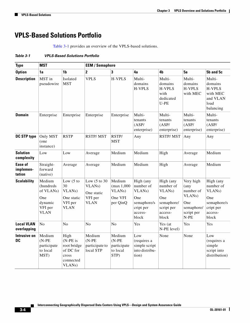
VPLS-Based Solutions PortfolioTable 3-1 provides an overview of the VPLS-based solutions.
Table 3-1 VPLS-Based Solutions Portfolio
Type MST EEM / Semaphore
Option 1a 1b 2 3 4a 4b 5a 5b and 5c
Description MST in pseudowire
Isolated MST
VPLS H-VPLS Multi- domains H-VPLS
Multi- domains H-VPLS with dedicated U-PE
Multi- domains H-VPLS with MEC
Multi- domains H-VPLS with MEC and VLAN load balancing
Domain Enterprise Enterprise Enterprise Enterprise Multi- tenants (ASP/ enterprise)
Multi- tenants (ASP/ enterprise)
Multi- tenants (ASP/ enterprise)
Multi- tenants (ASP/ enterprise)
DC STP type Only MST (one instance)
RSTP RSTP/ MST RSTP/ MST
Any RSTP/ MST Any Any
Solution complexity
Low Low Average Medium Medium High Average Medium
Ease of implemen- tation
Straight- forward (native)
Average Average Medium Medium High Average Medium
Scalability Medium (hundreds of VLANs)
One dynamic VFI per VLAN
Low (5 to 30 VLANs)
One static VFI per VLAN
Low (5 to 30 VLANs)
One static VFI per VLAN
Medium (max 1,000 VLANs)
One VFI per QinQ
High (any number of VLANs)
One semaphore/script per access- block
High (any number of VLANs)
One semaphore/script per access- block
Very high (any number of VLANs)
One semaphore/script per N-PE
High (any number of VLANs)
One semaphore/script per access- block
Local VLAN overlapping
No No No No Yes Yes (at N-PE level)
Yes Yes
Intrusive on DC
Medium (N-PE participate to local MST)
High (N-PE is root bridge of DC for cross connected VLANs)
Medium (N-PE participate to local STP
Medium (N-PE participate to local STP)
Low (requires a simple script into distribu- tion)
None None Low (requires a simple script into distribution)
3-4Interconnecting Geographically Dispersed Data Centers Using VPLS—Design and System Assurance Guide
OL-20161-01

Chapter 3 VPLS Overview and Solutions PortfolioVPLS-Based Solutions
Note VPLSoGRE with IP core—Options 2 and 4a were validated using Cisco Catalyst 6500 devices as VPLS nodes.
IOS native Yes 12.2(33)SRC1 or later IOS release
Partially (requires small additional scripts)
Requires EEM scripts in N-PE
Requires EEM scripts in N-PE
Requires EEM scripts in N-PE and in distribu- tion switches
Requires EEM scripts in N-PE and in U-PE
Requires EEM scripts in N-PE
Requires EEM scripts in N-PE and in distribu- tion switches
N-PE platform
Cisco 7600 Cisco 7600 Cisco 7600
(Cisco Catalyst 6500 for VPLSoGRE)
Cisco 7600 Cisco 7600
(Cisco Catalyst 6500 for VPLSoGRE)
Cisco 7600 Cisco 7600 Cisco 7600
Requires additional control- plane links
No No No Yes (TCN link to distribution and inter N-PE B-link)
Yes (E-link to trigger distribution script)
Yes (only between U-PE and N-PE, not toward distribution)
No Yes (E-link to trigger distribution script)
Table 3-1 VPLS-Based Solutions Portfolio (continued)
Type MST EEM / Semaphore
Option 1a 1b 2 3 4a 4b 5a 5b and 5c
3-5Interconnecting Geographically Dispersed Data Centers Using VPLS—Design and System Assurance Guide
OL-20161-01

Chapter 3 VPLS Overview and Solutions PortfolioVPLS-Based Solutions
3-6Interconnecting Geographically Dispersed Data Centers Using VPLS—Design and System Assurance Guide
OL-20161-01

Interconnecting Geographically Dispersed Data CentersOL-20161-01
C H A P T E R 4
Data Center Multitier Model and Testbed TopologyThis chapter describes the Cisco-recommended data center multitier model the testbed that was used to validate VPLS-based data center interconnect solutions. It includes these topics:
• Data Center Multitier Model, page 4-1
• Testbed Details, page 4-3
Data Center Multitier ModelA data center is home to the computational power, storage, and applications that support an enterprise business. The data center infrastructure is central to the IT architecture, from which all content is sourced or passes through. It is critical to properly plan the data center infrastructure design, and to carefully consider performance, resiliency, and scalability.
Data center design should also address flexibility to enable quickly deploying and supporting new services. Designing a flexible architecture that efficiently supports new applications can provide a significant competitive advantage. Such a design requires solid initial planning and thoughtful consideration of port density, access layer uplink bandwidth, true server capacity, oversubscription, and various other factor
The data center network design is based on a proven layered approach, which has been tested and improved over several years in some of the largest data center implementations. The layered approach provides the basic foundation of a data center design that improves scalability, performance, flexibility, resiliency, and maintenance. Figure 4-1 shows the basic layered design.
4-1 Using VPLS—Design and System Assurance Guide

Chapter 4 Data Center Multitier Model and Testbed TopologyData Center Multitier Model
Figure 4-1 Data Center Multi-Tier Model Topology
The data center includes the following layers:
• Core layer—Provides the high-speed packet switching backplane for all flows that pass in to and out of the data center. The core layer provides connectivity to multiple aggregation modules and provides a resilient Layer 3 routed fabric with no single point of failure. The core layer runs an interior routing protocol, such as OSPF or EIGRP, and load balances traffic between the campus core and aggregation layers by using Cisco Express Forwarding based hashing algorithms.
• Aggregation layer—Provides important functions, such as service module integration, Layer 2 domain definitions, spanning tree processing, and default gateway redundancy. Server-to-server multi-tier traffic flows through the aggregation layer and can use services such as firewall and server load balancing to optimize and secure applications. The smaller icons within the aggregation layer switch in Figure 4-1 represent the integrated service modules. These modules provide services, such as content switching, firewall, SSL offload, intrusion detection, network analysis, and more.
• Access layer—This layer is where the servers physically attach to the network. The server components consist of 1 RU servers, blade servers with integral switches, blade servers with pass-through cabling, clustered servers, and mainframes with OSA adapters. The access layer
Aggregation 4Aggregation 3
1433
11
DCCore
DCAggregation
DCAccess
Blade Chassis withpass thru modules
Mainframewith OSA
Layer 2 Access with clustering and NIC
teaming
Blade Chassiswith integrated
switch
Layer 3 Access withsmall broadcast domains
and isolated servers
Aggregation 2
10 Gigabit EthernetGigabit Ethernet or EtherchannelBackup
Campus Core
4-2Interconnecting Geographically Dispersed Data Centers Using VPLS—Design and System Assurance Guide
OL-20161-01
Chapter 4 Data Center Multitier Model and Testbed TopologyTestbed Details
network infrastructure consists of modular switches, fixed configuration 1 RU or 2 RU switches, and integral blade server switches. Switches provide both Layer 2 and Layer 3 topologies, fulfilling the various servers’ broadcast domain or administrative requirements.
Some access switches, known as Unified Fabric, support DCE/FCoE for unified I/O transport to attach to CNA-based servers and to unified computing systems. These emerging technologies are restricted to server access and cannot currently be extended via VPLS. For an overview of unified computing, refer to the following URL:
http://www.cisco.com/en/US/solutions/collateral/ns340/ns517/ns224/ns944/white_paper_c11-522754.html
For detailed information about each of the three layers of the data center design and their functions, refer to Cisco Data Center Infrastructure 2.5 Design Guide at the following URL:
http://www.cisco.com/application/pdf/en/us/guest/netsol/ns107/c649/ccmigration_09186a008073377d.pdf
Testbed DetailsDesign validation network consists of data centers interconnected via the enterprise core network. Each data center is built based on the data center multi-tier design that is described the “Data Center Multitier Model” section on page 4-1.
Figure 4-2 illustrates interconnected data centers. Dual N-PE routers have been added in addition to core, aggregation, and access layers in each data center.
4-3Interconnecting Geographically Dispersed Data Centers Using VPLS—Design and System Assurance Guide
OL-20161-01

Chapter 4 Data Center Multitier Model and Testbed TopologyTestbed Details
Figure 4-2 Data Center Interconnect Testbed Topology
Microsoft server cluster is implemented via 3 servers located within each data center. Two VLANs were provisioned for connectivity to public and private networks. These VLANs were then extended across data centers via pseudowire schemes as described in the solution section.
End-to-end service validation was performed by using traffic tools to generate IP unicast, multicast, and simulated voice traffic on the network. Health checks were performed before and after each test. These checks included memory and CPU utilization, tracebacks, memory alignment errors, deviations in number of routes and mroutes, interface errors, line card status and syslog messages.
Note Figure 4-2 refers to London, San Jose, and Singapore data centers. These names were selected to reflect remote locations or represent geographically dispersed locations and are not meant to imply the actual distances between these locations. The data centers were collocated in a lab with back-to-back fiber connections.
Hardware and Software Device InformationTable 4-1 provides information about the hardware and software that was used during testing.
4-4Interconnecting Geographically Dispersed Data Centers Using VPLS—Design and System Assurance Guide
OL-20161-01

Chapter 4 Data Center Multitier Model and Testbed TopologyTestbed Details
Convergence TestsThe purpose of these tests is to measure convergence times for voice, unicast, and multicast traffic during various link and node failures. In this test suite, convergence is measured from the data source to the receiver (end-to-end network convergence). During convergence, packet loss is determined for each individual flow. For example, packet rate of 1000 pps corresponds to 1 millisecond (ms) convergence time for each packet dropped.
Traffic Flow
Even though three data centers are used in all the designs documented in this guide, only two data centers, namely London and San Jose were used for convergence tests. Unidirectional traffic flows were provisioned across two data centers.
For each traffic type, i.e. unicast, multicast and voice:
• 58 unidirectional flows from London to San Jose
• 60 unidirectional flows from San Jose to London
Convergence tests were performed with all the three traffic types enabled simultaneously. Thus the total number of unidirectional traffic flows from London to San Jose were 174 and from San Jose to London were 180.
Table 4-1 Hardware and Software Device Information
Hardware Platform Role DRAM Software Version Line Cards / Interfaces
Cisco 7600
RSP720-3CXL-GE
N-PE RP—2GB
SP—2GB
12.2(33)SRC1 WS-X6724-SFP
7600-ES20-GE3C
WS-X6704-10GE
Catalyst 6500
Sup720-3BXL
N-PE1
1. Cisco Catalyst 6500 platforms were used as N-PEs in VPLSoGRE solutions.
RP—1GB
SP—1GB
12.2(33)SXH1 WS-X6724-SFP
WS-X6704-10GE
Catalyst 6500
Sup720-3BXL
DC core RP—1GB
SP—1GB
12.2(33)SXH 1 WS-X6724-SFP
WS-X6704-10GE
Catalyst 6500
Sup720-3BXL
VS-S720-10G
DC aggregation RP—1GB
SP—1GB
12.2(33)SXH 1
12.2(33)SXH2a (for VSS)
WS-X6704-10GE
WS-X6724-SFP
ACE20-MOD-K9
Catalyst 6500
Sup720-3BXL
DC access RP—1GB
SP - 1GB
12.2(33)SXH1 WS-X6724-SFP
Catalyst 4948 DC access 256 MB 12.2(40)SG WS-X4548-GB-RJ45
Catalyst 3750G DC access 256 MB 12.2(37)SE WS-C3750-24P
WS-C3750E-24
4-5Interconnecting Geographically Dispersed Data Centers Using VPLS—Design and System Assurance Guide
OL-20161-01

Chapter 4 Data Center Multitier Model and Testbed TopologyTestbed Details
Traffic Rate
Voice:
• Codec type—G711A
• Packet size—28 bytes
• Forwarding rate—50 pps; 1 packet every 20msec
• London to San Jose—2900 pps or 2.97 mbps
• San Jose to London—3000 pps or 3.07 mbps
Unicast:
• Packet size—128 bytes
• Forwarding rate—1000 pps
• London to San Jose—58000 pps or 59.39 mbps
• San Jose to London—60000 pps or 61.44 mbps
Multicast:
• 120 multicast groups with one source and one receiver per group
• Packet size—128 bytes
• Forwarding rate—100 pps
• London to San Jose—5800 pps or 5.93 mbps
• San Jose to London—6000 pps or 6.14 mbps
The above traffic profile was used in validating all the solutions documented in this design and assurance guide.
Traffic Profile
Table 4-2 lists the traffic flows from the London to San Jose and from the San Jose to London data centers.
Table 4-2 Traffic Flows
Voice Stream No.
Ixia Source Port
Ixia Dest Port
Source Switch Port
Dest Switch Port
Source VLAN
Source IP
Destina-tion VLAN
Destina-tion IP
Traffic Rate
Frame Size
Intra-VLAN 4-61 London -> San Jose
1 3/1 3/3 lon-a1 g4/17
sj-a1 g4/17
4 10.10.4.71
4 x 10.10.4.72
50 pps 128 bytes
… … … … … … … … x … … …
58 3/1 3/3 lon-a1 g4/17
sj-a1 g4/17
61 10.10.61.71
61 x 10.10.61.72
50 pps 128 bytes
1 3/1 3/3 lon-a1 g4/17
sj-a1 g4/17
4 10.10.4.61
4 239.254.4.4
10.10.4.62
100 pps 128 bytes
… … … … … … … … … … … …
58 3/1 3/3 lon-a1 g4/17
sj-a1 g4/17
61 10.10.61.61
61 239.254.4.61
10.10.61.62
100 pps 128 bytes
4-6Interconnecting Geographically Dispersed Data Centers Using VPLS—Design and System Assurance Guide
OL-20161-01

Chapter 4 Data Center Multitier Model and Testbed TopologyTestbed Details
Cluster Server TestsThe purpose of these tests is to measure cluster server convergence times between data centers for various link and node failures.
1 3/1 3/3 lon-a1 g4/17
sj-a1 g4/17
4 10.10.4.51
4 x 10.10.4.52
1000pps 128 bytes
… … … … … … … … x … … …
58 3/1 3/3 lon-a1 g4/17
sj-a1 g4/17
61 10.10.4.51
61 x 10.10.61.52
1000 pps
128 bytes
Intra-VLAN 201-260 San Jose--> London
1 3/4 3/2 sj-a2 g2/17
lon-a2 g2/17
201 10.30.1.72
201 x 10.30.1.71
50pps 128 bytes
… … … … … … … … x … … …
60 3/4 3/2 sj-a2 g2/17
lon-a2 g2/17
260 10.30.60.72
260 x 10.30.60.71
50pps 128 bytes
1 3/4 3/2 sj-a2 g2/17
lon-a2 g2/17
201 10.30.1.62
201 239.254.4.62
10.30.1.61
100pps 128 bytes
… … … … … … … … … … … …
60 3/4 3/2 sj-a2 g2/17
lon-a2 g2/17
260 10.30.60.62
260 239.254.4.121
10.30.60.61
100pps 128 bytes
Table 4-2 Traffic Flows (continued)
Voice Stream No.
Ixia Source Port
Ixia Dest Port
Source Switch Port
Dest Switch Port
Source VLAN
Source IP
Destina-tion VLAN
Destina-tion IP
Traffic Rate
Frame Size
4-7Interconnecting Geographically Dispersed Data Centers Using VPLS—Design and System Assurance Guide
OL-20161-01

Chapter 4 Data Center Multitier Model and Testbed TopologyTestbed Details
4-8Interconnecting Geographically Dispersed Data Centers Using VPLS—Design and System Assurance Guide
OL-20161-01

Interconnecting Geographically Dispersed Data CentersOL-20161-01
C H A P T E R 5
DCI Solution using Cisco 7600 Routers for MST-Based Data Centers (Option 1a)MST in N-PE, also known as MST in pseudowire using Layer 2 forwarding protocol, is available on Cisco 7600 platforms running Cisco IOS Software Release 12.2(33)SRC or later. The key aspect of this feature is the capability to create a pseudowire tunnel to carry only the MST Bridge Protocol Data Units (BPDUs) between the primary and backup N-PE within the data center through the Multiprotocol Label Switching (MPLS) cloud. This special pseudowire is not blocked by STP nor used to forward any data packets. However, this feature requires that the access network be designed so that one of the N-PEs is always the root of MST.
This solution that this chapter describes is MST in pseudowire, MST option 1a. This chapter includes these topics:
• Overview, page 5-1
• Configuration Summary, page 5-3
• Convergence Tests, page 5-14
• Cluster Server Tests, page 5-21
OverviewIn this solution, each data center is a separate MST region and STP between data centers is isolated via the VPLS core. MST instance 1 and 2 are created and all odd VLANs are assigned to MST instance 1 and all even VLANs to MST instance 2. In addition, MST instance priority on both N-PEs in the data center is configured so that N-PE1 becomes the root bridge for MST instance 1 and N-PE2 becomes the root bridge for MST instance 2.
Note In MST, only one BPDU is sent for all MST instances configured on the switch. This single BPDU carries all mappings between MST instances and the member VLANs.
You must configure multiple MST instances because, in MST, the STP cost can be applied only on a per MST instance basis and not on a per VLAN basis as with Rapid Per VLAN STP (RPVSTP). Configuration of the appropriate STP cost per MST instance ensures that certain VLANs are blocked on the dot1q trunk between the N-PE and the aggregation switch and the inter-aggregation dot1q trunk is always forwarding all VLANs, thus avoiding a loop in the topology and providing a mechanism to load balance VLANs between the two N-PE/Aggregation trunk links.
5-1 Using VPLS—Design and System Assurance Guide
Chapter 5 DCI Solution using Cisco 7600 Routers for MST-Based Data Centers (Option 1a)Overview
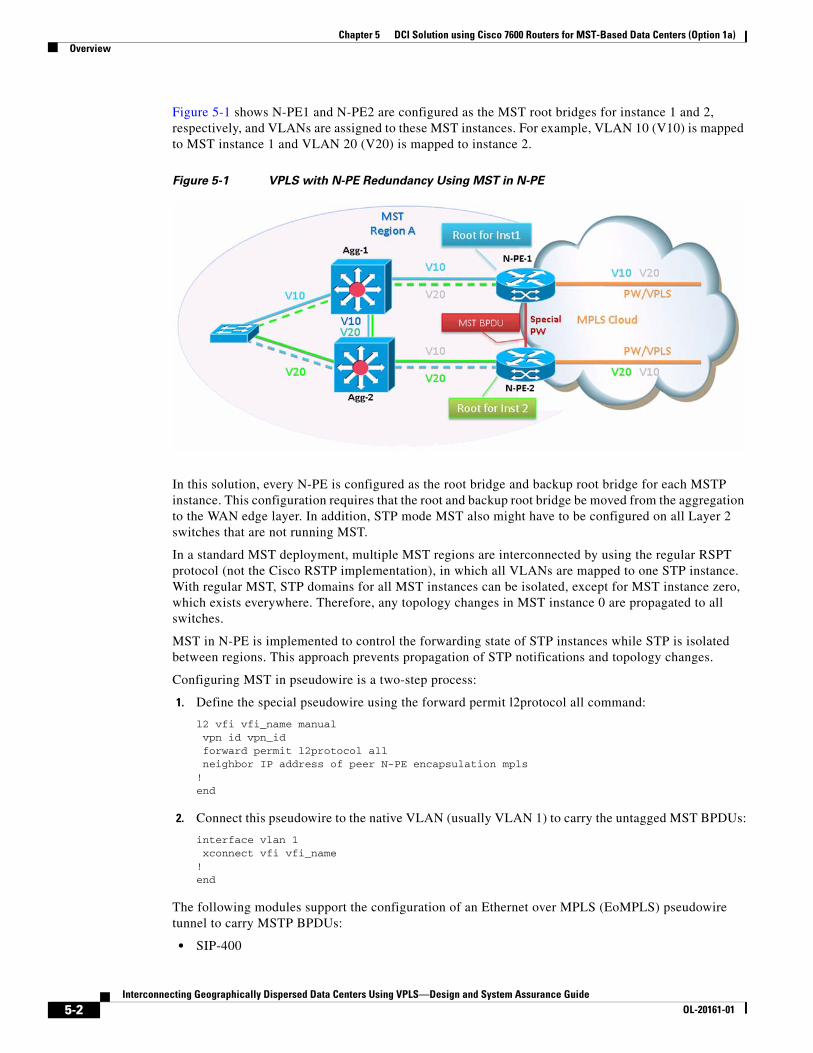
Figure 5-1 shows N-PE1 and N-PE2 are configured as the MST root bridges for instance 1 and 2, respectively, and VLANs are assigned to these MST instances. For example, VLAN 10 (V10) is mapped to MST instance 1 and VLAN 20 (V20) is mapped to instance 2.
Figure 5-1 VPLS with N-PE Redundancy Using MST in N-PE
In this solution, every N-PE is configured as the root bridge and backup root bridge for each MSTP instance. This configuration requires that the root and backup root bridge be moved from the aggregation to the WAN edge layer. In addition, STP mode MST also might have to be configured on all Layer 2 switches that are not running MST.
In a standard MST deployment, multiple MST regions are interconnected by using the regular RSPT protocol (not the Cisco RSTP implementation), in which all VLANs are mapped to one STP instance. With regular MST, STP domains for all MST instances can be isolated, except for MST instance zero, which exists everywhere. Therefore, any topology changes in MST instance 0 are propagated to all switches.
MST in N-PE is implemented to control the forwarding state of STP instances while STP is isolated between regions. This approach prevents propagation of STP notifications and topology changes.
Configuring MST in pseudowire is a two-step process:
1. Define the special pseudowire using the forward permit l2protocol all command:
l2 vfi vfi_name manual vpn id vpn_id forward permit l2protocol all neighbor IP address of peer N-PE encapsulation mpls!end
2. Connect this pseudowire to the native VLAN (usually VLAN 1) to carry the untagged MST BPDUs:
interface vlan 1 xconnect vfi vfi_name!end
The following modules support the configuration of an Ethernet over MPLS (EoMPLS) pseudowire tunnel to carry MSTP BPDUs:
• SIP-400
5-2Interconnecting Geographically Dispersed Data Centers Using VPLS—Design and System Assurance Guide
OL-20161-01

Chapter 5 DCI Solution using Cisco 7600 Routers for MST-Based Data Centers (Option 1a)Configuration Summary
• SIP-600
• ES-20
Configuration SummaryIn this solution, all pseudowires on N-PE1 and N-PE2 routers are active. Blocking of VLANs (loop avoidance) is performed on the links between the N-PEs and aggregation switches via STP cost associated with multiple MST instances.
The following provides snippets of configuration from N-PE and aggregation devices and output from various show commands.
1. Determine the existing STP root bridge priority for all VLANs that are required to be extended across data centers.
lon-n-pe1#sh spanning-tree vlan 7
MST0 Spanning tree enabled protocol mstp Root ID Priority 8192 Address 001d.7198.8fc0 Cost 0 Port 3329 (Port-channel1) Hello Time 2 sec Max Age 20 sec Forward Delay 15 sec
Bridge ID Priority 16384 (priority 16384 sys-id-ext 0) Address 001d.7198.9500 Hello Time 2 sec Max Age 20 sec Forward Delay 15 sec
Interface Role Sts Cost Prio.Nbr Type------------------- ---- --- --------- -------- --------------------------------Gi2/1 Desg FWD 20000 128.257 P2p Bound(PVST)
lon-n-pe1#
2. Configure STP mode MST on N-PE1. Configure N-PE1 as the root bridge for MST instance 0 and 1 by reducing the bridge priority to a value lower than the value found in step 1. Similarly, configure N-PE2 as the root bridge for MST instance 2. Assign all odd VLANs to MST instance 1 and all even VLANs to MST instance 2. Lower the priority for MST instances 0-2 such that N-PE1 becomes the backup root bridge for all the even VLANs and N-PE2, the backup root bridge for all odd VLANs:
N-PE1 Configuration N-PE2 Configuration
spanning-tree mode mst!spanning-tree mst configurationname lon-datacenterrevision 10instance 1 vlan 1, 3, 5, 7, 9, 11, 13, 15, 17, 19, 21, 23, 25, 27, 29 ...instance 2 vlan 2, 4, 6, 8, 10, 12, 14, 16, 18, 20, 22, 24, 26, 28, 30 ...!spanning-tree mst 0-1 priority 8192 spanning-tree mst 2 priority 16384!vlan 2-61,201-260
spanning-tree mode mst!spanning-tree mst configurationname lon-datacenterrevision 10instance 1 vlan 1, 3, 5, 7, 9, 11, 13, 15, 17, 19, 21, 23, 25, 27, 29 ...instance 2 vlan 2, 4, 6, 8, 10, 12, 14, 16, 18, 20, 22, 24, 26, 28, 30 ...!spanning-tree mst 0-1 priority 16384spanning-tree mst 2 priority 8192!vlan 2-61,201-260
5-3Interconnecting Geographically Dispersed Data Centers Using VPLS—Design and System Assurance Guide
OL-20161-01

Chapter 5 DCI Solution using Cisco 7600 Routers for MST-Based Data Centers (Option 1a)Configuration Summary
3. Verify MST configuration on the both the N-PEs.
N-PE1 ConfigurationN-PE2 Configurationspanning-tree mode mst!spanning-tree mst configurationname lon-datacenterrevision 10instance 1 vlan 1, 3, 5, 7, 9, 11, 13, 15, 17, 19, 21, 23, 25, 27, 29 ...instance 2 vlan 2, 4, 6, 8, 10, 12, 14, 16, 18, 20, 22, 24, 26, 28, 30 ...!spanning-tree mst 0-1 priority 8192 spanning-tree mst 2 priority 16384!vlan 2-61,201-260spanning-tree mode mst!spanning-tree mst configurationname lon-datacenterrevision 10instance 1 vlan 1, 3, 5, 7, 9, 11, 13, 15, 17, 19, 21, 23, 25, 27, 29 ...instance 2 vlan 2, 4, 6, 8, 10, 12, 14, 16, 18, 20, 22, 24, 26, 28, 30 ...!spanning-tree mst 0-1 priority 16384spanning-tree mst 2 priority 8192!vlan 2-61,201-260Step 3.Verify MST configuration on the both the N-PEs.! On N-PE1:lon-n-pe1#show spanning-tree mst detail
##### MST0 vlans mapped: 62-200,261-300,302,304-4094Bridge address 001d.7198.9500 priority 8192 (8192 sysid 0)Root this switch for the CISTOperational hello time 2 , forward delay 15, max age 20, txholdcount 6 Configured hello time 2 , forward delay 15, max age 20, max hops 20
GigabitEthernet2/1 of MST0 is designated forwardingPort info port id 128.257 priority 128 cost 20000Designated root address 001d.7198.9500 priority 8192 cost 0Design. regional root address 001d.7198.9500 priority 8192 cost 0Designated bridge address 001d.7198.9500 priority 8192 port id 128.257Timers: message expires in 0 sec, forward delay 0, forward transitions 1Bpdus sent 11083, received 4
BRIDGE4/132 of MST0 is designated forwardingPort info port id 128.900 priority 128 cost 200Designated root address 001d.7198.9500 priority 8192 cost 0Design. regional root address 001d.7198.9500 priority 8192 cost 0Designated bridge address 001d.7198.9500 priority 8192 port id 128.900Timers: message expires in 0 sec, forward delay 0, forward transitions 23Bpdus sent 30369, received 18330
BRIDGE4/196 of MST0 is designated forwardingPort info port id 128.964 priority 128 cost 200Designated root address 001d.7198.9500 priority 8192 cost 0Design. regional root address 001d.7198.9500 priority 8192 cost 0Designated bridge address 001d.7198.9500 priority 8192 port id 128.964Timers: message expires in 0 sec, forward delay 0, forward transitions 24Bpdus sent 30416, received 11409
##### MST1 vlans mapped: 1,3,5,7,9,11,13,15,17,19,21,23,25,27,29 31,33,35,37,39,41,43,45,47,49,51,53,55,57 59,61,201,203,205,207,209,211,213,215,217
5-4Interconnecting Geographically Dispersed Data Centers Using VPLS—Design and System Assurance Guide
OL-20161-01

Chapter 5 DCI Solution using Cisco 7600 Routers for MST-Based Data Centers (Option 1a)Configuration Summary
219,221,223,225,227,229,231,233,235,237 239,241,243,245,247,249,251,253,255,257 259,301,303Bridge address 001d.7198.9500 priority 8193 (8192 sysid 1)Root this switch for MST1
GigabitEthernet2/1 of MST1 is designated forwardingPort info port id 128.257 priority 128 cost 20000Designated root address 001d.7198.9500 priority 8193 cost 0Designated bridge address 001d.7198.9500 priority 8193 port id 128.257Timers: message expires in 0 sec, forward delay 0, forward transitions 1Bpdus (MRecords) sent 11083, received 4
BRIDGE4/132 of MST1 is designated forwardingPort info port id 128.900 priority 128 cost 200Designated root address 001d.7198.9500 priority 8193 cost 0Designated bridge address 001d.7198.9500 priority 8193 port id 128.900Timers: message expires in 0 sec, forward delay 0, forward transitions 23Bpdus (MRecords) sent 30369, received 18329
BRIDGE4/196 of MST1 is designated forwardingPort info port id 128.964 priority 128 cost 200Designated root address 001d.7198.9500 priority 8193 cost 0Designated bridge address 001d.7198.9500 priority 8193 port id 128.964Timers: message expires in 0 sec, forward delay 0, forward transitions 24Bpdus (MRecords) sent 30416, received 11408
##### MST2 vlans mapped: 2,4,6,8,10,12,14,16,18,20,22,24,26,28,30 32,34,36,38,40,42,44,46,48,50,52,54,56,58 60,202,204,206,208,210,212,214,216,218,220 222,224,226,228,230,232,234,236,238,240 242,244,246,248,250,252,254,256,258,260Bridge address 001d.7198.9500 priority 16386 (16384 sysid 2)Root address 001d.7198.8fc0 priority 8194 (8192 sysid 2) port BR4/132 cost 200 rem hops 19
GigabitEthernet2/1 of MST2 is designated forwardingPort info port id 128.257 priority 128 cost 20000Designated root address 001d.7198.8fc0 priority 8194 cost 200Designated bridge address 001d.7198.9500 priority 16386 port id 128.257Timers: message expires in 0 sec, forward delay 0, forward transitions 1Bpdus (MRecords) sent 11083, received 4
BRIDGE4/132 of MST2 is root forwardingPort info port id 128.900 priority 128 cost 200Designated root address 001d.7198.8fc0 priority 8194 cost 0Designated bridge address 001d.7198.8fc0 priority 8194 port id 128.900Timers: message expires in 4 sec, forward delay 0, forward transitions 22Bpdus (MRecords) sent 30369, received 18329
BRIDGE4/196 of MST2 is designated forwardingPort info port id 128.964 priority 128 cost 200Designated root address 001d.7198.8fc0 priority 8194 cost 200Designated bridge address 001d.7198.9500 priority 16386 port id 128.964Timers: message expires in 0 sec, forward delay 0, forward transitions 24Bpdus (MRecords) sent 30416, received 11408
lon-n-pe1#lon-n-pe1#show running-config interface gig 2/1Building configuration...
Current configuration : 384 bytes!interface GigabitEthernet2/1
5-5Interconnecting Geographically Dispersed Data Centers Using VPLS—Design and System Assurance Guide
OL-20161-01
Chapter 5 DCI Solution using Cisco 7600 Routers for MST-Based Data Centers (Option 1a)Configuration Summary
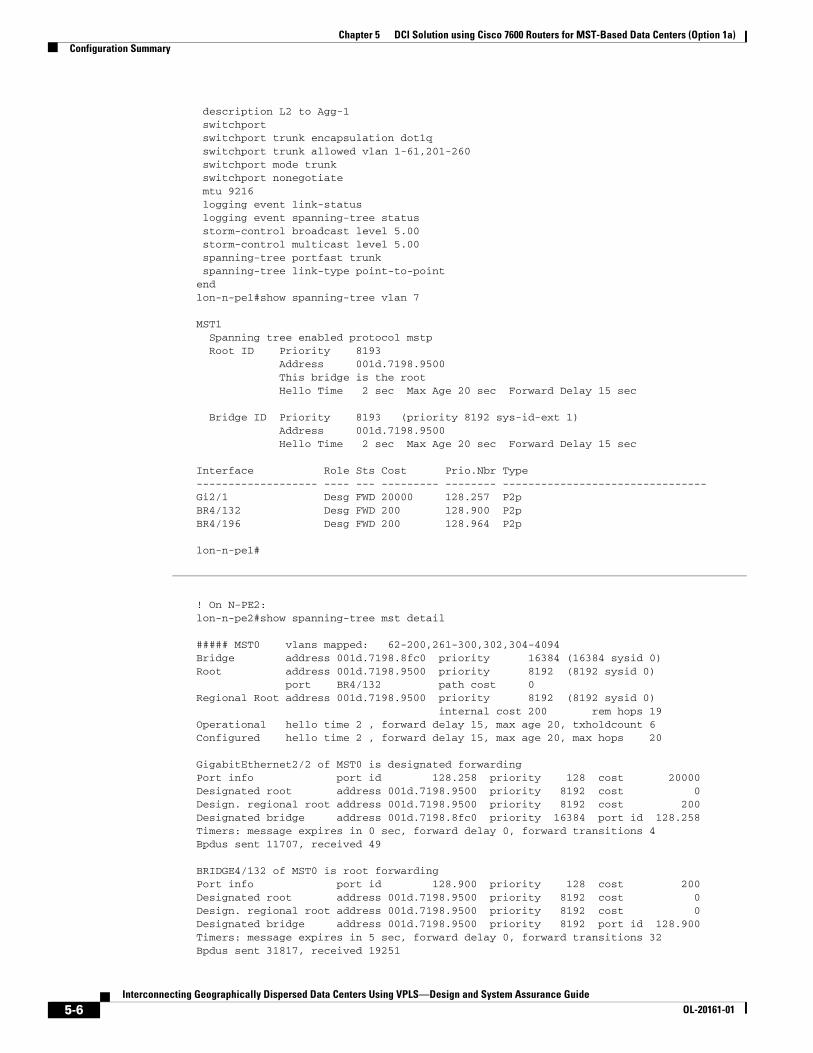
description L2 to Agg-1 switchport switchport trunk encapsulation dot1q switchport trunk allowed vlan 1-61,201-260 switchport mode trunk switchport nonegotiate mtu 9216 logging event link-status logging event spanning-tree status storm-control broadcast level 5.00 storm-control multicast level 5.00 spanning-tree portfast trunk spanning-tree link-type point-to-pointendlon-n-pe1#show spanning-tree vlan 7
MST1 Spanning tree enabled protocol mstp Root ID Priority 8193 Address 001d.7198.9500 This bridge is the root Hello Time 2 sec Max Age 20 sec Forward Delay 15 sec
Bridge ID Priority 8193 (priority 8192 sys-id-ext 1) Address 001d.7198.9500 Hello Time 2 sec Max Age 20 sec Forward Delay 15 sec
Interface Role Sts Cost Prio.Nbr Type------------------- ---- --- --------- -------- --------------------------------Gi2/1 Desg FWD 20000 128.257 P2p BR4/132 Desg FWD 200 128.900 P2p BR4/196 Desg FWD 200 128.964 P2p
lon-n-pe1#
! On N-PE2:lon-n-pe2#show spanning-tree mst detail
##### MST0 vlans mapped: 62-200,261-300,302,304-4094Bridge address 001d.7198.8fc0 priority 16384 (16384 sysid 0)Root address 001d.7198.9500 priority 8192 (8192 sysid 0) port BR4/132 path cost 0 Regional Root address 001d.7198.9500 priority 8192 (8192 sysid 0) internal cost 200 rem hops 19Operational hello time 2 , forward delay 15, max age 20, txholdcount 6 Configured hello time 2 , forward delay 15, max age 20, max hops 20
GigabitEthernet2/2 of MST0 is designated forwardingPort info port id 128.258 priority 128 cost 20000Designated root address 001d.7198.9500 priority 8192 cost 0Design. regional root address 001d.7198.9500 priority 8192 cost 200Designated bridge address 001d.7198.8fc0 priority 16384 port id 128.258Timers: message expires in 0 sec, forward delay 0, forward transitions 4Bpdus sent 11707, received 49
BRIDGE4/132 of MST0 is root forwardingPort info port id 128.900 priority 128 cost 200Designated root address 001d.7198.9500 priority 8192 cost 0Design. regional root address 001d.7198.9500 priority 8192 cost 0Designated bridge address 001d.7198.9500 priority 8192 port id 128.900Timers: message expires in 5 sec, forward delay 0, forward transitions 32Bpdus sent 31817, received 19251
5-6Interconnecting Geographically Dispersed Data Centers Using VPLS—Design and System Assurance Guide
OL-20161-01

Chapter 5 DCI Solution using Cisco 7600 Routers for MST-Based Data Centers (Option 1a)Configuration Summary
BRIDGE4/196 of MST0 is designated forwardingPort info port id 128.964 priority 128 cost 200Designated root address 001d.7198.9500 priority 8192 cost 0Design. regional root address 001d.7198.9500 priority 8192 cost 200Designated bridge address 001d.7198.8fc0 priority 16384 port id 128.964Timers: message expires in 0 sec, forward delay 0, forward transitions 45Bpdus sent 31868, received 11415
##### MST1 vlans mapped: 1,3,5,7,9,11,13,15,17,19,21,23,25,27,29 31,33,35,37,39,41,43,45,47,49,51,53,55,57 59,61,201,203,205,207,209,211,213,215,217 219,221,223,225,227,229,231,233,235,237 239,241,243,245,247,249,251,253,255,257 259,301,303Bridge address 001d.7198.8fc0 priority 16385 (16384 sysid 1)Root address 001d.7198.9500 priority 8193 (8192 sysid 1) port BR4/132 cost 200 rem hops 19
GigabitEthernet2/2 of MST1 is designated forwardingPort info port id 128.258 priority 128 cost 20000Designated root address 001d.7198.9500 priority 8193 cost 200Designated bridge address 001d.7198.8fc0 priority 16385 port id 128.258Timers: message expires in 0 sec, forward delay 0, forward transitions 4Bpdus (MRecords) sent 11707, received 45
BRIDGE4/132 of MST1 is root forwardingPort info port id 128.900 priority 128 cost 200Designated root address 001d.7198.9500 priority 8193 cost 0Designated bridge address 001d.7198.9500 priority 8193 port id 128.900Timers: message expires in 5 sec, forward delay 0, forward transitions 23Bpdus (MRecords) sent 31817, received 19251
BRIDGE4/196 of MST1 is designated forwardingPort info port id 128.964 priority 128 cost 200Designated root address 001d.7198.9500 priority 8193 cost 200Designated bridge address 001d.7198.8fc0 priority 16385 port id 128.964Timers: message expires in 0 sec, forward delay 0, forward transitions 35Bpdus (MRecords) sent 31868, received 11415
##### MST2 vlans mapped: 2,4,6,8,10,12,14,16,18,20,22,24,26,28,30 32,34,36,38,40,42,44,46,48,50,52,54,56,58 60,202,204,206,208,210,212,214,216,218,220 222,224,226,228,230,232,234,236,238,240 242,244,246,248,250,252,254,256,258,260Bridge address 001d.7198.8fc0 priority 8194 (8192 sysid 2)Root this switch for MST2
GigabitEthernet2/2 of MST2 is designated forwardingPort info port id 128.258 priority 128 cost 20000Designated root address 001d.7198.8fc0 priority 8194 cost 0Designated bridge address 001d.7198.8fc0 priority 8194 port id 128.258Timers: message expires in 0 sec, forward delay 0, forward transitions 4Bpdus (MRecords) sent 11707, received 45
BRIDGE4/132 of MST2 is designated forwardingPort info port id 128.900 priority 128 cost 200Designated root address 001d.7198.8fc0 priority 8194 cost 0Designated bridge address 001d.7198.8fc0 priority 8194 port id 128.900Timers: message expires in 0 sec, forward delay 0, forward transitions 32Bpdus (MRecords) sent 31817, received 19251
BRIDGE4/196 of MST2 is designated forwardingPort info port id 128.964 priority 128 cost 200
5-7Interconnecting Geographically Dispersed Data Centers Using VPLS—Design and System Assurance Guide
OL-20161-01

Chapter 5 DCI Solution using Cisco 7600 Routers for MST-Based Data Centers (Option 1a)Configuration Summary
Designated root address 001d.7198.8fc0 priority 8194 cost 0Designated bridge address 001d.7198.8fc0 priority 8194 port id 128.964Timers: message expires in 0 sec, forward delay 0, forward transitions 44Bpdus (MRecords) sent 31868, received 11415
lon-n-pe2#lon-n-pe2#show running-config interface gig 2/2Building configuration...
Current configuration : 374 bytes!interface GigabitEthernet2/2 description L2 to Agg-2 switchport switchport trunk encapsulation dot1q switchport trunk allowed vlan 1-61,201-260 switchport mode trunk switchport nonegotiate mtu 9216 load-interval 30 storm-control broadcast level 5.00 storm-control multicast level 5.00 spanning-tree portfast trunk spanning-tree link-type point-to-pointendlon-n-pe2#show spanning-tree vlan 7
MST1 Spanning tree enabled protocol mstp Root ID Priority 8193 Address 001d.7198.9500 Cost 200 Port 900 (BRIDGE4/132) Hello Time 2 sec Max Age 20 sec Forward Delay 15 sec
Bridge ID Priority 16385 (priority 16384 sys-id-ext 1) Address 001d.7198.8fc0 Hello Time 2 sec Max Age 20 sec Forward Delay 15 sec
Interface Role Sts Cost Prio.Nbr Type------------------- ---- --- --------- -------- --------------------------------Gi2/2 Desg FWD 20000 128.258 P2p BR4/132 Root FWD 200 128.900 P2p BR4/196 Desg FWD 200 128.964 P2p
lon-n-pe2#
4. Ensure that all Layer 2 switches in the local data center are running MST. If they are not, configure spanning tree mode MST and allocate all odd VLANs to MST instance 1 and all even VLANs to MST instance 2 on all the Agg PEs and access switches:
! On Agg-1 , Agg-2, Access-1, and Access-2:spanning-tree mode mst!spanning-tree mst configurationname lon-datacenterrevision 10instance 1 vlan 1, 3, 5, 7, 9, 11, 13, 15, 17, 19, 21, 23, 25, 27, 29 ..instance 2 vlan 2, 4, 6, 8, 10, 12, 14, 16, 18, 20, 22, 24, 26, 28, 30 ..!vlan 2-61,201-260
5. On the link between both N-PEs and aggregation switches, configure the following:
5-8Interconnecting Geographically Dispersed Data Centers Using VPLS—Design and System Assurance Guide
OL-20161-01
Chapter 5 DCI Solution using Cisco 7600 Routers for MST-Based Data Centers (Option 1a)Configuration Summary
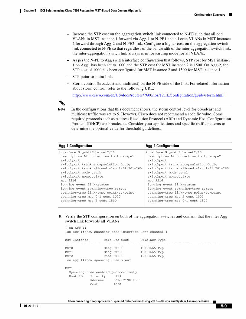
– Increase the STP cost on the aggregation switch link connected to N-PE such that all odd VLANs in MST instance 1 forward via Agg-1 to N-PE1 and all even VLANs in MST instance 2 forward through Agg-2 and N-PE2 link. Configure a higher cost on the aggregation switch link connected to N-PE so that regardless of the bandwidth of the inter-aggregation switch link, the inter-aggregation switch link always is in forwarding mode for all VLANs.
– As per the N-PE to Agg switch interface configuration that follows, STP cost for MST instance 1 on Agg1 has been set to 1000 and the STP cost for MST instance 2 is 1500. On Agg-2, the STP cost of 1000 has been configured for MST instance 2 and 1500 for MST instance 1.
– STP point-to-point link.
– Storm control (broadcast and multicast) on the N-PE side of the link. For related information about storm control, refer to the following URL:
http://www.cisco.com/en/US/docs/routers/7600/ios/12.1E/configuration/guide/storm.html
Note In the configurations that this document shows, the storm control level for broadcast and multicast traffic was set to 5. However, Cisco does not recommend a specific value. Some required protocols such as Address Resolution Protocol (ARP) and Dynamic Host Configuration Protocol (DHCP) use broadcasts. Consider your applications and specific traffic patterns to determine the optimal value for threshold guidelines.
6. Verify the STP configuration on both of the aggregation switches and confirm that the inter Agg switch link forwards all VLANs:
! On Agg-1:lon-agg-1#show spanning-tree interface Port-channel 1
Mst Instance Role Sts Cost Prio.Nbr Type------------------- ---- --- --------- -------- --------------------------------MST0 Desg FWD 1 128.1665 P2p MST1 Desg FWD 1 128.1665 P2p MST2 Root FWD 1 128.1665 P2p lon-agg-1#show spanning-tree vlan7
MST1 Spanning tree enabled protocol mstp Root ID Priority 8193 Address 001d.7198.9500 Cost 1000
Agg-1 Configuration Agg-2 Configuration
interface GigabitEthernet2/19 description L2 connection to lon-n-pe1 switchport switchport trunk encapsulation dot1q switchport trunk allowed vlan 1-61,201-260 switchport mode trunk switchport nonegotiate mtu 9216 logging event link-status logging event spanning-tree status spanning-tree link-type point-to-point spanning-tree mst 0-1 cost 1000 spanning-tree mst 2 cost 1500
interface GigabitEthernet2/18 description L2 connection to lon-n-pe2 switchport switchport trunk encapsulation dot1q switchport trunk allowed vlan 1-61,201-260 switchport mode trunk switchport nonegotiate mtu 9216 logging event link-status logging event spanning-tree status spanning-tree link-type point-to-point spanning-tree mst 2 cost 1000 spanning-tree mst 0-1 cost 1500
5-9Interconnecting Geographically Dispersed Data Centers Using VPLS—Design and System Assurance Guide
OL-20161-01

Chapter 5 DCI Solution using Cisco 7600 Routers for MST-Based Data Centers (Option 1a)Configuration Summary
Port 147 (GigabitEthernet2/19) Hello Time 2 sec Max Age 20 sec Forward Delay 15 sec
Bridge ID Priority 32769 (priority 32768 sys-id-ext 1) Address 001c.b126.d000 Hello Time 2 sec Max Age 20 sec Forward Delay 15 sec
Interface Role Sts Cost Prio.Nbr Type------------------- ---- --- --------- -------- --------------------------------Gi2/19 Root FWD 1000 128.147 P2pGi2/22 Desg FWD 20000 128.150 P2p Po1 Desg FWD 1 128.1665 P2p
! On Agg-2:lon-agg-2#show spanning-tree interface Port-channel 1
Mst Instance Role Sts Cost Prio.Nbr Type------------------- ---- --- --------- -------- -------------------------------MST0 Root FWD 1 128.1665 P2p MST1 Root FWD 1 128.1665 P2p MST2 Desg FWD 1 128.1665 P2p
lon-agg-2#show spanning-tree vlan 7
MST1 Spanning tree enabled protocol mstp Root ID Priority 8193 Address 001d.7198.9500 Cost 1001 Port 1665 (Port-channel1) Hello Time 2 sec Max Age 20 sec Forward Delay 15 sec
Bridge ID Priority 32769 (priority 32768 sys-id-ext 1) Address 001c.b144.4c00 Hello Time 2 sec Max Age 20 sec Forward Delay 15 sec
Interface Role Sts Cost Prio.Nbr Type------------------- ---- --- --------- -------- --------------------------------Gi2/18 Altn BLK 1500 128.146 P2pGi2/21 Desg FWD 20000 128.149 P2p Po1 Root FWD 1 128.1665 P2p
From the output of show spanning-tree vlan 7, you can see that spanning tree blocks odd VLANs on the link between N-PE2 and Agg-2. Also, all VLANs are in forwarding state on the inter-aggregation switch link. This configuration provides per-MST instance VLAN load balancing and avoids Layer 2 loop.
7. Configure OSPF on the N-PE routers:
router ospf 1 router-id 11.11.11.11 log-adjacency-changes auto-cost reference-bandwidth 10000 area 0 authentication message-digest timers throttle spf 100 100 5000 timers throttle lsa 100 100 5000 timers lsa arrival 80 ... distribute-list 1 in GigabitEthernet2/6 bfd all-interfaces mpls ldp sync!
5-10Interconnecting Geographically Dispersed Data Centers Using VPLS—Design and System Assurance Guide
OL-20161-01

Chapter 5 DCI Solution using Cisco 7600 Routers for MST-Based Data Centers (Option 1a)Configuration Summary
lon-n-pe1#show ip ospf 1 Routing Process "ospf 1" with ID 11.11.11.11 Start time: 00:00:50.580, Time elapsed: 06:14:40.996 Supports only single TOS(TOS0) routes Supports opaque LSA Supports Link-local Signaling (LLS) Supports area transit capability Event-log enabled, Maximum number of events: 1000, Mode: cyclic Router is not originating router-LSAs with maximum metric Initial SPF schedule delay 100 msecs Minimum hold time between two consecutive SPFs 100 msecs Maximum wait time between two consecutive SPFs 5000 msecs Incremental-SPF disabled Initial LSA throttle delay 100 msecs Minimum hold time for LSA throttle 100 msecs Maximum wait time for LSA throttle 5000 msecs Minimum LSA arrival 80 msecs LSA group pacing timer 240 secs Interface flood pacing timer 33 msecs Retransmission pacing timer 66 msecs Number of external LSA 1. Checksum Sum 0x00D71C Number of opaque AS LSA 0. Checksum Sum 0x000000 Number of DCbitless external and opaque AS LSA 0 Number of DoNotAge external and opaque AS LSA 0 Number of areas in this router is 1. 1 normal 0 stub 0 nssa Number of areas transit capable is 0 External flood list length 0 IETF NSF helper support enabled Cisco NSF helper support enabled BFD is enabled Reference bandwidth unit is 10000 mbps Area BACKBONE(0) Number of interfaces in this area is 6 (2 loopback) Area has message digest authentication SPF algorithm last executed 00:55:35.412 ago SPF algorithm executed 68 times Area ranges are Number of LSA 22. Checksum Sum 0x099D4E Number of opaque link LSA 0. Checksum Sum 0x000000 Number of DCbitless LSA 0 Number of indication LSA 0 Number of DoNotAge LSA 0 Flood list length 0
lon-n-pe1#show ip ospf neighbor
Neighbor ID Pri State Dead Time Address Interface116.5.200.77 0 FULL/ - 00:00:39 192.168.11.7 GigabitEthernet4/0/1912.12.12.12 0 FULL/ - 00:00:37 192.168.13.6 GigabitEthernet4/0/013.13.13.13 0 FULL/ - 00:00:35 10.11.21.3 GigabitEthernet2/6
lon-n-pe1#show cdp neighbors
Capability Codes: R - Router, T - Trans Bridge, B - Source Route Bridge S - Switch, H - Host, I - IGMP, r - Repeater, P - Phone
Device ID Local Intrfce Holdtme Capability Platform Port IDlon-n-pe2 Gig 4/0/0 150 R S I CISCO7604 Gig 4/0/0lon-agg-1 Gig 2/1 144 R S I WS-C6509- Gig 2/19lon-core1 Gig 2/6 151 R S I WS-C6506 Gig 3/21mpls-p1 Gig 4/0/19 149 R S I WS-C6506 Gig 2/22
5-11Interconnecting Geographically Dispersed Data Centers Using VPLS—Design and System Assurance Guide
OL-20161-01

Chapter 5 DCI Solution using Cisco 7600 Routers for MST-Based Data Centers (Option 1a)Configuration Summary
8. Configure MPLS, VFI and SVI with l2transport show commands on N-PEs is shown below. MST in pseudowire is implemented with a separate VFI-bpdu-pw. Redundancy in the VPLS domain relies on an MPLS mechanism. Each N-PE will have an alternate MPLS path, or an EEM policy can be used at each N-PE to shut down its link to the local Agg switch when the VPLS link is down.
! On N-PE1:lon-n-pe1#!...mpls ldp neighbor 10.76.70.12 targeted ldpmpls ldp neighbor 10.76.70.21 targeted ldpmpls ldp neighbor 10.76.70.22 targeted ldpmpls ldp neighbor 10.76.70.31 targeted ldpmpls ldp neighbor 10.76.70.32 targeted ldpmpls ldp tcp pak-prioritympls ldp session protectionno mpls ldp advertise-labelsmpls ldp advertise-labels for 76mpls label protocol ldp!xconnect logging pseudowire status!access-list 76 permit 10.76.0.0 0.0.255.255! VFI for MST in PW l2 vfi bpdu-pw manual vpn id 1 forward permit l2protocol all neighbor 10.76.100.12 encapsulation mpls! VFI for VLAN 7 l2 vfi lon-pe1-7 manual vpn id 7 neighbor 10.76.100.32 encapsulation mpls neighbor 10.76.100.31 encapsulation mpls neighbor 10.76.100.22 encapsulation mpls neighbor 10.76.100.21 encapsulation mpls!!interface Vlan7 mtu 9216 no ip address xconnect vfi lon-pe1-7!lon-n-pe1#show mpls l2transport vc
Local intf Local circuit Dest address VC ID Status ------------- -------------------------- --------------- ---------- ----------VFI bpdu-pw VFI 10.76.100.11 1 UPVFI lon-pe2-7 VFI 10.76.100.21 7 UP VFI lon-pe2-7 VFI 10.76.100.22 7 UP VFI lon-pe2-7 VFI 10.76.100.31 7 UP VFI lon-pe2-7 VFI 10.76.100.32 7 UP
Lon-n-pe1#lon-n-pe1#show running-config interface gig 4/0/19!interface GigabitEthernet4/0/19 description L3 connection to MPLS P router dampening mtu 9216 ip address 192.168.11.5 255.255.255.0 ip ospf message-digest-key 1 md5 lab ip ospf network point-to-point
5-12Interconnecting Geographically Dispersed Data Centers Using VPLS—Design and System Assurance Guide
OL-20161-01

Chapter 5 DCI Solution using Cisco 7600 Routers for MST-Based Data Centers (Option 1a)Configuration Summary
load-interval 30 carrier-delay msec 0 mls qos trust dscp mpls ip bfd interval 100 min_rx 100 multiplier 3end
! On N-PE2:lon-n-pe2#! VFI for MST in PWl2 vfi bpdu-pw manual vpn id 1 forward permit l2protocol all neighbor 10.76.100.11 encapsulation mpls << lon-n-pe1!l2 vfi lon-pe2-7 manual vpn id 7 neighbor 10.76.100.32 encapsulation mpls << sj-n-pe2 neighbor 10.76.100.31 encapsulation mpls << sj-n-pe1 neighbor 10.76.100.22 encapsulation mpls << sin-n-pe2 neighbor 10.76.100.21 encapsulation mpls << sin-n-pe1!!interface Vlan7 mtu 9216 no ip address xconnect vfi lon-pe2-7!lon-n-pe2#show mpls l2transport vc
Local intf Local circuit Dest address VC ID Status ------------- -------------------------- --------------- ---------- ----------VFI bpdu-pw VFI 10.76.100.11 1 UPVFI lon-pe2-7 VFI 10.76.100.21 7 UP VFI lon-pe2-7 VFI 10.76.100.22 7 UP VFI lon-pe2-7 VFI 10.76.100.31 7 UP VFI lon-pe2-7 VFI 10.76.100.32 7 UPLon-n-pe2#
9. EEM configuration and show commands.
lon-n-pe1#!process-max-time 50!track 20 interface GigabitEthernet4/0/0 line-protocol!track 21 interface GigabitEthernet4/0/19 line-protocol!track 25 list boolean or object 20 object 21 delay up 90
lon-n-pe1#show running-config | begin event managerevent manager applet DOWN_Gig2/1 event track 25 state down action 1.0 cli command "enable" action 2.0 cli command "config t" action 3.0 cli command "int Gig 2/1 " action 4.0 cli command "shut" action 5.0 syslog msg "EEM has shut Gig 2/1 "
5-13Interconnecting Geographically Dispersed Data Centers Using VPLS—Design and System Assurance Guide
OL-20161-01

Chapter 5 DCI Solution using Cisco 7600 Routers for MST-Based Data Centers (Option 1a)Convergence Tests
event manager applet UP_Gig2/1 event track 25 state up action 1.0 cli command "enable" action 2.0 cli command "config t" action 3.0 cli command "int Gig2/1" action 4.0 cli command "no shut" action 5.0 syslog msg "EEM has unshut Gig2/1"event manager applet DOWN_GIG2/1-boot event timer cron name "_EEMinternalname6" cron-entry "@reboot" action 1.0 cli command "enable" action 2.0 cli command "config t" action 3.0 cli command "interface Gig 2/1 " action 4.0 cli command "shutdown" action 5.0 syslog msg "EEM has shut Gig 2/1 "!end
Pertaining to the bolded line of output: When an N-PE router reloads, power to the LAN modules is enabled before the WAN modules power on. In this situation, LAN interfaces are enabled before interfaces on the WAN modules become active. After the LAN interfaces become active, spanning tree converges and puts the interface between N-PE and aggregation switch in forwarding mode. Therefore, traffic is black-holed because the WAN interfaces might still be in down state or the path to the core network might not be available via the N-PE that was reloaded. An EEM reboot applet ensures that the LAN interfaces are in shut state until the WAN interfaces configured in track command become active after the router initializes completely.
Convergence TestsThe traffic profile that is outlined in the “Traffic Profile” section on page 4-6 was used to determine end-to-end convergence for unidirectional voice, unicast, and multicast traffic. Links and nodes were failed to simulate network failures.
Table 5-1 shows results of various nodes and links failures. Convergence numbers (Max and Min) are in seconds.
5-14Interconnecting Geographically Dispersed Data Centers Using VPLS—Design and System Assurance Guide
OL-20161-01

Chapter 5 DCI Solution using Cisco 7600 Routers for MST-Based Data Centers (Option 1a)Convergence Tests
Table 5-1 Convergence Numbers for DCI Solution using Cisco 7600 Routers for MST-Based Data
Centers (MST Option 1a)
Traffic Direction
LON -> SJ SJ -> LON
Failure Type Action VLAN Traffic Type Max Min Max Min
Node Failure
Reload N-PE1 Reload Odd VLAN1 Voice 3.92 3.84 3.78 3.76
Unicast 3.91 3.87 3.77 3.75
Multicast 6.37 4.06 6.61 3.93
Even VLAN Voice 0.14 0.12 0.00 0.00
Unicast 0.14 0.14 0.00 0.00
Multicast 0.15 0.13 0.00 0.00
Restore Odd VLAN Voice 0.44 0.02 0.73 0.73
Unicast 0.43 0.16 0.71 0.18
Multicast 8.43 0.92 5.47 2.45
Even VLAN Voice 0.00 0.73 0.02 0.02
Unicast 0.00 0.00 0.00 0.00
Multicast 0.00 0.00 0.00 0.00
Reload N-PE2 Reload Odd VLAN Voice 0.02 0.02 0.02 0.02
Unicast 0.00 0.00 0.00 0.00
Multicast 0.01 0.00 0.02 0.02
Even VLAN1 Voice 3.76 3.66 3.76 3.74
Unicast 3.73 3.68 3.74 3.72
Multicast 6.30 4.18 6.00 3.84
Restore Odd VLAN Voice 0.02 0.02 0.02 0.02
Unicast 0.00 0.00 0.00 0.00
Multicast 0.10 0.00 0.03 0.02
Even VLAN Voice 1.18 0.62 1.34 1.28
Unicast 1.15 0.62 1.32 0.72
Multicast 4.68 0.97 6.04 0.96
5-15Interconnecting Geographically Dispersed Data Centers Using VPLS—Design and System Assurance Guide
OL-20161-01

Chapter 5 DCI Solution using Cisco 7600 Routers for MST-Based Data Centers (Option 1a)Convergence Tests
Reload Agg-1 Reload Odd VLAN Voice 0.50 0.02 0.50 0.50
Unicast 0.47 0.47 0.48 0.48
Multicast 4.59 2.49 1.21 0.67
Even VLAN Voice 0.02 0.02 0.02 0.02
Unicast 0.00 0.00 0.00 0.00
Multicast 0.03 0.01 0.03 0.01
Restore Odd VLAN Voice 0.06 0.02 0.04 0.04
Unicast 0.03 0.02 0.00 0.00
Multicast 2.89 0.76 2.00 0.02
Even VLAN Voice 0.02 0.02 0.04 0.04
Unicast 0.00 0.00 0.00 0.00
Multicast 0.01 0.00 0.02 0.02
Reload Agg-2 Reload Odd VLAN Voice 0.46 0.00 0.00 0.00
Unicast 0.00 0.00 0.00 0.00
Multicast 0.00 0.00 0.00 0.00
Even VLAN Voice 0.48 0.46 0.46 0.46
Unicast 0.47 0.46 0.46 0.46
Multicast 4.53 1.76 7.06 0.79
Restore Odd VLAN Voice 0.02 0.00 0.02 0.02
Unicast 0.00 0.00 0.00 0.00
Multicast 0.00 0.00 0.01 0.01
Even VLAN Voice 0.06 0.02 0.02 0.02
Unicast 0.04 0.04 0.01 0.01
Multicast 1.74 0.28 1.07 0.02
Table 5-1 Convergence Numbers for DCI Solution using Cisco 7600 Routers for MST-Based Data
Centers (MST Option 1a) (continued)
Traffic Direction
LON -> SJ SJ -> LON
Failure Type Action VLAN Traffic Type Max Min Max Min
5-16Interconnecting Geographically Dispersed Data Centers Using VPLS—Design and System Assurance Guide
OL-20161-01

Chapter 5 DCI Solution using Cisco 7600 Routers for MST-Based Data Centers (Option 1a)Convergence Tests
Link Failure
Fail L2 link between N-PE1 and Agg-1
Shut Odd VLAN Voice 0.90 0.87 0.30 0.24
Unicast 0.89 0.89 0.30 0.23
Multicast 5.55 0.97 2.60 0.56
Even VLAN Voice 0.00 0.24 0.00 0.00
Unicast 0.00 0.00 0.00 0.00
Multicast 0.01 0.00 0.02 0.01
No shut Odd VLAN Voice 0.28 0.02 0.36 0.26
Unicast 0.29 0.20 0.33 0.18
Multicast 4.29 0.46 3.32 0.28
Even VLAN Voice 0.02 0.02 0.02 0.02
Unicast 0.00 0.00 0.00 0.00
Multicast 0.01 0.00 0.00 0.00
Fail L2 link between N-PE2 and Agg-2
Shut Odd VLAN Voice 0.58 0.00 0.02 0.02
Unicast 0.00 0.00 0.00 0.00
Multicast 0.02 0.00 0.01 0.01
Even VLAN Voice 0.62 0.58 0.60 0.58
Unicast 0.59 0.57 0.58 0.56
Multicast 5.75 2.26 5.94 2.25
No shut Odd VLAN Voice 0.02 0.02 0.00 0.00
Unicast 0.00 0.00 0.00 0.00
Multicast 0.01 0.00 0.01 0.01
Even VLAN Voice 0.64 0.40 0.72 0.72
Unicast 0.63 0.41 0.71 0.63
Multicast 6.86 1.52 2.74 1.03
Table 5-1 Convergence Numbers for DCI Solution using Cisco 7600 Routers for MST-Based Data
Centers (MST Option 1a) (continued)
Traffic Direction
LON -> SJ SJ -> LON
Failure Type Action VLAN Traffic Type Max Min Max Min
5-17Interconnecting Geographically Dispersed Data Centers Using VPLS—Design and System Assurance Guide
OL-20161-01

Chapter 5 DCI Solution using Cisco 7600 Routers for MST-Based Data Centers (Option 1a)Convergence Tests
Fail L2 link between Agg-1 and Agg-2
Shut Odd VLAN Voice 0.00 0.00 0.00 0.00
Unicast 0.00 0.00 0.00 0.00
Multicast 0.01 0.00 0.00 0.00
Even VLAN Voice 0.00 0.00 0.00 0.00
Unicast 0.00 0.00 0.00 0.00
Multicast 0.01 0.00 0.01 0.01
No shut Odd VLAN Voice 0.00 0.00 0.00 0.00
Unicast 0.00 0.00 0.00 0.00
Multicast 0.01 0.00 0.00 0.00
Even VLAN Voice 0.00 0.00 0.00 0.00
Unicast 0.00 0.00 0.00 0.00
Multicast 0.01 0.00 0.01 0.01
Fail Wan link facing core on N-PE1
Shut Odd VLAN Voice 0.56 0.04 0.54 0.46
Unicast 0.53 0.51 0.51 0.43
Multicast 2.48 1.37 0.52 0.44
Even VLAN Voice 0.02 0.02 0.04 0.04
Unicast 0.00 0.00 0.00 0.00
Multicast 0.01 0.00 0.01 0.01
No shut Odd VLAN Voice 0.02 0.02 0.02 0.02
Unicast 0.00 0.00 0.00 0.00
Multicast 3.60 0.17 0.02 0.02
Even VLAN Voice 0.02 0.02 0.02 0.02
Unicast 0.00 0.00 0.00 0.00
Multicast 0.01 0.00 0.02 0.02
Table 5-1 Convergence Numbers for DCI Solution using Cisco 7600 Routers for MST-Based Data
Centers (MST Option 1a) (continued)
Traffic Direction
LON -> SJ SJ -> LON
Failure Type Action VLAN Traffic Type Max Min Max Min
5-18Interconnecting Geographically Dispersed Data Centers Using VPLS—Design and System Assurance Guide
OL-20161-01

Chapter 5 DCI Solution using Cisco 7600 Routers for MST-Based Data Centers (Option 1a)Convergence Tests
Fail Wan link facing core on N-PE2
Shut Odd VLAN Voice 0.06 0.02 0.02 0.02
Unicast 0.01 0.01 0.01 0.00
Multicast 0.02 0.00 0.01 0.01
Even VLAN Voice 0.62 0.56 0.54 0.50
Unicast 0.61 0.56 0.54 0.27
Multicast 3.44 0.61 0.54 0.27
No shut Odd VLAN Voice 0.02 0.02 0.04 0.04
Unicast 0.01 0.00 0.00 0.00
Multicast 0.02 0.00 0.01 0.01
Even VLAN Voice 0.02 0.02 0.12 0.10
Unicast 0.00 0.00 0.06 0.06
Multicast 3.12 0.14 0.07 0.07
Fail both WAN links on N-PE1
Shut Odd VLAN1 Voice 3.88 0.04 3.98 3.98
Unicast 3.86 3.85 3.99 3.99
Multicast 6.54 4.81 7.42 4.28
Even VLAN Voice 0.02 0.02 0.04 0.04
Unicast 0.02 0.02 0.01 0.01
Multicast 0.01 0.00 0.02 0.02
No shut Odd VLAN Voice 0.26 0.06 0.54 0.54
Unicast 0.26 0.06 0.54 0.26
Multicast 4.25 0.35 4.51 0.58
Even VLAN Voice 0.54 0.00 0.00 0.00
Unicast 0.00 0.00 0.00 0.00
Multicast 0.01 0.00 0.00 0.00
Table 5-1 Convergence Numbers for DCI Solution using Cisco 7600 Routers for MST-Based Data
Centers (MST Option 1a) (continued)
Traffic Direction
LON -> SJ SJ -> LON
Failure Type Action VLAN Traffic Type Max Min Max Min
5-19Interconnecting Geographically Dispersed Data Centers Using VPLS—Design and System Assurance Guide
OL-20161-01

Chapter 5 DCI Solution using Cisco 7600 Routers for MST-Based Data Centers (Option 1a)Convergence Tests
Fail both WAN links on N-PE2
Shut Odd VLAN Voice 0.02 0.02 0.04 0.02
Unicast 0.00 0.00 0.00 0.00
Multicast 0.01 0.00 0.00 0.00
Even VLAN1 Voice 2.86 2.82 2.86 2.86
Unicast 2.84 2.84 2.84 2.84
Multicast 2.85 2.84 4.76 4.56
No shut Odd VLAN Voice 0.06 0.02 0.02 0.02
Unicast 0.01 0.00 0.00 0.00
Multicast 0.02 0.01 0.00 0.00
Even VLAN Voice 0.43 0.08 0.50 0.46
Unicast 0.44 0.10 0.48 0.12
Multicast 5.28 0.86 2.62 0.85
Clear entire routing table on both N-PEs
Clear Odd VLAN Voice 0.02 0.02 0.00 0.00
Unicast 0.00 0.00 0.00 0.00
Multicast 0.00 0.00 0.01 0.01
Even VLAN Voice 0.00 0.00 0.00 0.00
Unicast 0.00 0.00 0.00 0.00
Multicast 0.01 0.00 0.01 0.01
Clear entire dynamic MAC address table on both N-PEs
Clear Odd VLAN Voice 0.00 0.00 0.00 0.00
Unicast 0.00 0.00 0.00 0.00
Multicast 0.01 0.00 0.00 0.00
Even VLAN Voice 0.00 0.00 0.00 0.00
Unicast 0.00 0.00 0.00 0.00
Multicast 0.01 0.00 0.01 0.01
Table 5-1 Convergence Numbers for DCI Solution using Cisco 7600 Routers for MST-Based Data
Centers (MST Option 1a) (continued)
Traffic Direction
LON -> SJ SJ -> LON
Failure Type Action VLAN Traffic Type Max Min Max Min
5-20Interconnecting Geographically Dispersed Data Centers Using VPLS—Design and System Assurance Guide
OL-20161-01

Chapter 5 DCI Solution using Cisco 7600 Routers for MST-Based Data Centers (Option 1a)Cluster Server Tests
Cluster Server TestsEvent logs are captured from event viewer of Microsoft cluster server. The logs are in the reverse order showing the last event, first. It is best to view the timestamps when analyzing these logs.
Table 5-2 shows the event logs from the event viewer of Microsoft cluster server.
Fail L3 links between N-PEs
Shut Odd VLAN Voice 0.00 0.00 0.00 0.00
Unicast 0.00 0.00 0.00 0.00
Multicast 0.01 0.00 0.00 0.00
Even VLAN Voice 0.00 0.00 0.00 0.00
Unicast 0.00 0.00 0.00 0.00
Multicast 0.01 0.00 0.01 0.01
No shut Odd VLAN Voice 0.00 0.00 0.00 0.00
Unicast 0.00 0.00 0.00 0.00
Multicast 0.01 0.00 0.01 0.00
Even VLAN Voice 0.00 0.00 0.00 0.00
Unicast 0.00 0.00 0.00 0.00
Multicast 0.01 0.00 0.01 0.01
1. If the EoMPLS pseudowire carrying MST BPDUs between the N-PEs fails, MST convergence within the local data center takes longer due to the delay in propagation of topology change notification. Cisco defect number CSCsk85658 documents this issue.
Table 5-1 Convergence Numbers for DCI Solution using Cisco 7600 Routers for MST-Based Data
Centers (MST Option 1a) (continued)
Traffic Direction
LON -> SJ SJ -> LON
Failure Type Action VLAN Traffic Type Max Min Max Min
5-21Interconnecting Geographically Dispersed Data Centers Using VPLS—Design and System Assurance Guide
OL-20161-01
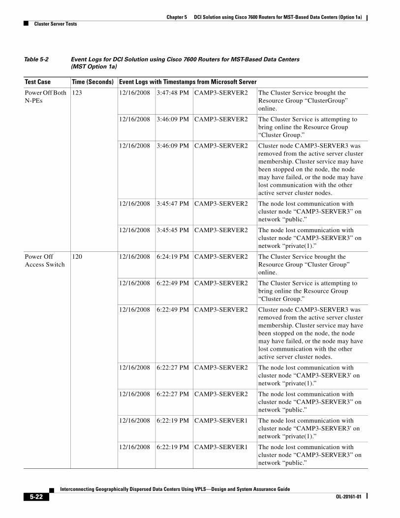
Chapter 5 DCI Solution using Cisco 7600 Routers for MST-Based Data Centers (Option 1a)Cluster Server Tests
Table 5-2 Event Logs for DCI Solution using Cisco 7600 Routers for MST-Based Data Centers (MST Option 1a)
Test Case Time (Seconds) Event Logs with Timestamps from Microsoft Server
Power Off Both N-PEs
123 12/16/2008 3:47:48 PM CAMP3-SERVER2 The Cluster Service brought the Resource Group “ClusterGroup” online.
12/16/2008 3:46:09 PM CAMP3-SERVER2 The Cluster Service is attempting to bring online the Resource Group “Cluster Group.”
12/16/2008 3:46:09 PM CAMP3-SERVER2 Cluster node CAMP3-SERVER3 was removed from the active server cluster membership. Cluster service may have been stopped on the node, the node may have failed, or the node may have lost communication with the other active server cluster nodes.
12/16/2008 3:45:47 PM CAMP3-SERVER2 The node lost communication with cluster node “CAMP3-SERVER3” on network “public.”
12/16/2008 3:45:45 PM CAMP3-SERVER2 The node lost communication with cluster node “CAMP3-SERVER3” on network “private(1).”
Power Off Access Switch
120 12/16/2008 6:24:19 PM CAMP3-SERVER2 The Cluster Service brought the Resource Group “Cluster Group” online.
12/16/2008 6:22:49 PM CAMP3-SERVER2 The Cluster Service is attempting to bring online the Resource Group “Cluster Group.”
12/16/2008 6:22:49 PM CAMP3-SERVER2 Cluster node CAMP3-SERVER3 was removed from the active server cluster membership. Cluster service may have been stopped on the node, the node may have failed, or the node may have lost communication with the other active server cluster nodes.
12/16/2008 6:22:27 PM CAMP3-SERVER2 The node lost communication with cluster node “CAMP3-SERVER3' on network “private(1).”
12/16/2008 6:22:27 PM CAMP3-SERVER2 The node lost communication with cluster node “CAMP3-SERVER3” on network “public.”
12/16/2008 6:22:19 PM CAMP3-SERVER1 The node lost communication with cluster node “CAMP3-SERVER3' on network “private(1).”
12/16/2008 6:22:19 PM CAMP3-SERVER1 The node lost communication with cluster node “CAMP3-SERVER3” on network “public.”
5-22Interconnecting Geographically Dispersed Data Centers Using VPLS—Design and System Assurance Guide
OL-20161-01

Chapter 5 DCI Solution using Cisco 7600 Routers for MST-Based Data Centers (Option 1a)Cluster Server Tests
Power Off Active Node
125 12/16/2008 5:54:19 PM CAMP3-SERVER2 The Cluster Service brought the Resource Group “Cluster Group” online.
12/16/2008 5:52:44 PM CAMP3-SERVER2 The Cluster Service is attempting to bring online the Resource Group “ClusterGroup.”
12/16/2008 5:52:44 PM CAMP3-SERVER2 Cluster node CAMP3-SERVER3 was removed from the active server cluster membership. Cluster service may have been stopped on the node, the node may have failed, or the node may have lost communication with the other active server cluster nodes.
12/16/2008 5:52:22 PM CAMP3-SERVER2 The node lost communication with cluster node “CAMP3-SERVER3” on network “private(1).”
12/16/2008 5:52:22 PM CAMP3-SERVER2 The node lost communication with cluster node “CAMP3-SERVER3” on network “public.”
12/16/2008 5:52:14 PM CAMP3-SERVER1 The node lost communication with cluster node “CAMP3-SERVER3” on network “private(1).”
12/16/2008 5:52:14 PM CAMP3-SERVER1 The node lost communication with cluster node “CAMP3-SERVER3” on network “public.”
Private VLAN NPE reload
6 12/16/2008 5:35:23 PM CAMP3-SERVER2 Cluster network “private(1)” is operational (up). All available server cluster nodes attached to the network can communicate using it.
12/16/2008 5:35:20 PM CAMP3-SERVER3 The node (re)established communication with cluster node “CAMP3-SERVER2” on network “private(1).”
12/16/2008 5:35:20 PM CAMP3-SERVER3 The node (re)established communication with cluster node “CAMP3-SERVER1” on network “private(1).”
12/16/2008 5:35:14 PM CAMP3-SERVER3 The node lost communication with cluster node “CAMP3-SERVER2” on network “private(1).”
12/16/2008 5:35:14 PM CAMP3-SERVER3 The node lost communication with cluster node “CAMP3-SERVER1” on network “private(1).”
Table 5-2 Event Logs for DCI Solution using Cisco 7600 Routers for MST-Based Data Centers (MST Option 1a) (continued)
Test Case Time (Seconds) Event Logs with Timestamps from Microsoft Server
5-23Interconnecting Geographically Dispersed Data Centers Using VPLS—Design and System Assurance Guide
OL-20161-01

Chapter 5 DCI Solution using Cisco 7600 Routers for MST-Based Data Centers (Option 1a)Cluster Server Tests
Unplug Active Server
125 12/16/2008 5:54:19 PM CAMP3-SERVER2 The Cluster Service brought the Resource Group “Cluster Group” online.
12/16/2008 5:52:44 PM CAMP3-SERVER2 The Cluster Service is attempting to bring online the Resource Group “Cluster Group.”
12/16/2008 5:52:44 PM CAMP3-SERVER2 Cluster node CAMP3-SERVER3 was removed from the active server cluster membership. Cluster service might have been stopped on the node, the node might have failed, or the node might have lost communication with the other active server cluster nodes.
12/16/2008 5:52:22 PM CAMP3-SERVER2 The node lost communication with cluster node “CAMP3-SERVER3” on network “public.”
12/16/2008 5:52:14 PM CAMP3-SERVER1 The node lost communication with cluster node “CAMP3-SERVER3” on network “public.”
Establish L2 Connectivity
No Convergence
12/16/2008 6:36:03 PM CAMP3-SERVER2 The Cluster Service service entered the running state.
12/16/2008 6:36:02 PM CAMP3-SERVER2 Cluster service successfully joined the server cluster CLUSTER-MNS.
12/16/2008 6:35:44 PM CAMP3-SERVER2 The node (re)established communication with cluster node “CAMP3-SERVER3” on network “public.”
12/16/2008 6:35:44 PM CAMP3-SERVER2 The node (re)established communication with cluster node “CAMP3-SERVER3” on network “private(1).”
12/16/2008 6:35:43 PM CAMP3-SERVER2 The node (re)established communication with cluster node “CAMP3-SERVER1” on network “public.”
12/16/2008 6:35:43 PM CAMP3-SERVER2 The node (re)established communication with cluster node “CAMP3-SERVER1” on network “private(1).”
12/16/2008 6:35:35 PM CAMP3-SERVER2 The Cluster Service service was successfully sent a start control.
Table 5-2 Event Logs for DCI Solution using Cisco 7600 Routers for MST-Based Data Centers (MST Option 1a) (continued)
Test Case Time (Seconds) Event Logs with Timestamps from Microsoft Server
5-24Interconnecting Geographically Dispersed Data Centers Using VPLS—Design and System Assurance Guide
OL-20161-01

Interconnecting Geographically Dispersed Data CentersOL-20161-01
C H A P T E R 6
Scalable H-VPLS DCI Solution using Cisco 7600 Routers (Option 5c)The MST solution that Chapter 5, “DCI Solution using Cisco 7600 Routers for MST-Based Data Centers (Option 1a)” describes, spanning tree provides redundant access to VPLS nodes to manage the states of links that connect aggregation switches to VPLS nodes (N-PEs). The solution that this chapter describes is scalable H-VPLS with MEC and VLAN load balancing, EEM option 5c, which provides high availability for link and node failures by using MEC technology to connect data center aggregation. It also provides scalability based on 802.1q in 802.1q (QinQ) technology and supports multiple edge domain with overlapping VLANs.
This solution does not require modification of the local data center STP design. The pseudowires on the backup N-PE are always in UP state, which accelerates the activation of a backup path if a primary path fails. This solution requires the aggregation device to support MEC via VSS on Cisco Catalyst 6500 platforms or vPC on Cisco Nexus 7000 platforms.
In the absence of Inter Chassis Communication Protocol (ICCP), VPLS node state synchronization is achieved by a set of validated scripts that are executed in IOS by the Embedded Event Manager (EEM). EEM scripts provide synchronization of VPLS nodes by using a semaphore concept.
As discussed in Chapter 3, “VPLS Overview and Solutions Portfolio,” there are several EEM semaphore based solutions that provide N-PE redundancy. These solutions can easily be adapted for data centers with a wide variety of data center formats and various types of connectivity to aggregations switches.
This chapter includes these topics:
• Introduction to Semaphores, page 6-1
• Overview, page 6-2
• N-PE Routers: Hardware and Software, page 6-3
• Convergence Tests, page 6-8
Introduction to SemaphoresSemaphores are event indicators that actively monitor the states of the primary and backup VPLS nodes. Primary semaphore (P-semaphore) and backup semaphore (B-semaphore) are dedicated loopback interfaces on an N-PE. EEM tracks the reachability of the B-semaphore on the primary N-PE and the reachability of the P-semaphore on the backup N-PE. Primary and backup N-PE states are synchronized via the advertisement of IP addresses of these loopback interfaces by the core IGP.
6-1 Using VPLS—Design and System Assurance Guide

Chapter 6 Scalable H-VPLS DCI Solution using Cisco 7600 Routers (Option 5c)Overview
In each of the EEM based designs, semaphores play a major role in synchronizing the states between primary and backup N-PE to achieve redundancy at the chassis level. They facilitate a dual handshake mechanism between both N-PEs in the data center and ensure that the backup path activates only if the primary path fails, thus preventing an active-active state that would lead to a bridging loop. As long as the P-semaphore is active and is reachable by the backup node, the backup or the standby PW is in shut state. Therefore, there is only one PW active at any given time, which prevents layer 2 loops in the global topology.
OverviewIn this scalable H-VPLS DCI solution, MEC (VSS or Nexus vPC) in the aggregation layer is connected by using one EtherChannel toward each N-PE. This EEM based solution allows PWs on backup N-PEs also to be in UP state. This solution accelerates the activation of the backup path if the primary path fails. The backup PW is in UP state, but does not forward traffic. An EEM script ensures that one service instance within an EtherChannel is cross-connected toward only one multipoint VFI at any time, thus avoiding a loop in the topology.
As with all the EEM based deployment models, the PW topology is based on the split-horizon concept. All primary N-PE routers are fully meshed with the remote primary and backup N-PE routers. The backup N-PE routers have only pseudowires toward the remote primary N-PEs; there are no pseudowires configured between the backup N-PE routers.
Figure 6-1 illustrates H-VPLS with MEC using VSS/vPC in aggregation.
Figure 6-1 H-VPLS with VSS/vPC and MEC
The pseudowires on the primary and backup N-PEs are always in UP state and service instance is ATTACHED/DETACHED from the bridge-domain on the backup N-PE. The concept is to forward edge traffic to a null QinQ VLAN until the backup path needs to be activated, thus avoiding a Layer 2 loop in the global topology. If the primary path fails, EEM maps the edge traffic to a QinQ VLAN that is connected to VFI. A dummy edge-VLAN, for example 998, is configured solely to keep the VFI in UP state and to prevent the autostate function from automatically shutting down the VFI. In normal mode, which is under no failure condition, VLANs are associated with a null bridge-domain on the QinQ link that connects the backup N-PE to the aggregation switch.
6-2Interconnecting Geographically Dispersed Data Centers Using VPLS—Design and System Assurance Guide
OL-20161-01

Chapter 6 Scalable H-VPLS DCI Solution using Cisco 7600 Routers (Option 5c)N-PE Routers: Hardware and Software
Selective QinQ is configured on the N-PE side of the link connection to aggregation. This configuration allows the creation of several service instances to groom edge-VLAN. Each service instance is associated with a bridge-domain that is cross-connected to a VFI . The VFI uses a pseudowire to connect over the core toward the remote nodes. See the “Configuration Summary” section on page 6-3 for detailed information.
N-PE Routers: Hardware and Software Table 6-2 shows the hardware and software required for N-PE nodes. Cisco 7600 routers were used as N-PEs for all the MST and EEM-based solutions that this document describes. In this solution, selective QinQ with two EVCs were configured using ES-20 modules facing the aggregation. Also, the aggregation switches must support EEM script which can be triggered on a specific syslog message or on the link state.
In addition, Enhanced Object Tracking is required to perform route watch of peer node semaphore.
Aggregation devices must support Multi-chassis EtherChannel (MEC) that allows EtherChannel to span two physical devices. This approach takes advantage of of VSS (Virtual Switching System) technology on Cisco Catalyst 6500 devices and Virtual Port Channel (vPC ) on Cisco Nexus 7000 devices.
Configuration SummaryThe following configuration from N-PE1 and N-PE2 routers highlight the framework of the UP/UP pseudowire solution.
On N-PE1:
vlan 2-61,201-260,998-999 !vlan 3001 name H-VPLS_Primary_core_VLAN!vlan 3004 name H-VPLS_Backup_core_VLAN!l2 vfi VFI-Even manual vpn id 3002 neighbor 10.76.90.22 encapsulation mpls neighbor 10.76.90.32 encapsulation mpls!l2 vfi VFI-Odd manual vpn id 3001
Table 6-1 Hardware and Software for N-PE Nodes
Hardware/Software Cisco 7600 Router
Facing core Interfaces on SIP or ES modules are required for connectivity toward VPLS core
Facing edge ES module due to selective QinQ requirement in this solution
E-link Interface on any WS-X67xx LAN or ES module; does not carry any traffic
Software Cisco IOS version 12.2(33)SRC1
6-3Interconnecting Geographically Dispersed Data Centers Using VPLS—Design and System Assurance Guide
OL-20161-01

Chapter 6 Scalable H-VPLS DCI Solution using Cisco 7600 Routers (Option 5c)N-PE Routers: Hardware and Software
neighbor 10.76.91.32 encapsulation mpls neighbor 10.76.91.31 encapsulation mpls neighbor 10.76.91.21 encapsulation mpls neighbor 10.76.91.22 encapsulation mpls!interface Vlan3001 description Primary Core QinQ VLAN - used to transport Odd edge VLAN mtu 9216 no ip address xconnect vfi VFI-Odd! interface Vlan3004 description Backup Core QinQ VLAN - used to transport Even edge VLAN mtu 9216 no ip address xconnect vfi VFI-Even
interface Port-channel31 description used for QinQ ES20 card facing Aggregation (Multi-Etherchannel toward VSS) mtu 9216 ip arp inspection limit none no ip address logging event bundle-status load-interval 30 mls qos trust dscp spanning-tree portfast trunk service instance 998 ethernet description Dummy to hold Vlan 3004 up encapsulation dot1q 998 bridge-domain 3004 ! service instance 999 ethernet description Dummy to hold Vlan 3001 up encapsulation dot1q 999 bridge-domain 3001 ! service instance 3001 ethernet encapsulation dot1q 1,3,5,7,9,11,13,15,17,19,21,23,25,27,29,31,33,35,37,39,41,43,45,47,49,51,53,55,57,59,61,201,203,205,207,209,211,213,215,217,219,221,223,225,227,229,231,233,235,237,239,241,243,245,247,249,251,253,255,257,259 bridge-domain 3001 ! service instance 3004 ethernet encapsulation dot1q 2,4,6,8,10,12,14,16,18,20,22,24,26,28,30,32,34,36,38,40,42,44,46,48,50,52,54,56,58,60,202,204,206,208,210,212,214,216,218,220,222,224,226,228,230,232,234,236,238,240,242,244,246,248,250,252,254,256,258,260 bridge-domain 998
lon-n-pe1#sh cdp neighCapability Codes: R - Router, T - Trans Bridge, B - Source Route Bridge S - Switch, H - Host, I - IGMP, r - Repeater, P - Phone
Device ID Local Intrfce Holdtme Capability Platform Port IDcampus3-223sw8 Gig 1/2 156 S I WS-C2950T Fas 0/2lon-n-pe2 Ten 4/0/0 127 R S I CISCO7604 Ten 4/0/0lon-agg-1 Ten 2/0/1 135 R S I WS-C6509- Ten 2/7/12lon-agg-1 Ten 3/1 179 R S I WS-C6509- Ten 1/7/6lon-agg-1 Ten 2/0/0 138 R S I WS-C6509- Ten 1/7/11CRS1-mpls-p1 Ten 4/0/1 147 R CRS-1 TenGigE0/0/0/0lon-core1 Ten 3/2 161 R S I WS-C6506 Ten 1/2lon-n-pe1#
6-4Interconnecting Geographically Dispersed Data Centers Using VPLS—Design and System Assurance Guide
OL-20161-01

Chapter 6 Scalable H-VPLS DCI Solution using Cisco 7600 Routers (Option 5c)N-PE Routers: Hardware and Software
lon-n-pe1#sh mpls l2transport vc
Local intf Local circuit Dest address VC ID Status ------------- -------------------------- --------------- ---------- ----------VFI VFI-Odd VFI 10.76.70.21 3001 UP VFI VFI-Odd VFI 10.76.70.22 3001 UP VFI VFI-Even VFI 10.76.70.22 3002 UP VFI VFI-Odd VFI 10.76.70.31 3001 UP VFI VFI-Odd VFI 10.76.70.32 3001 UP VFI VFI-Even VFI 10.76.70.32 3002 UP lon-n-pe1#
On N-PE2:
vlan 2-61,201-260,998-999 !vlan 3002 name H-VPLS_Primary_core_VLAN!vlan 3003 name H-VPLS_Backup_core_VLAN!l2 vfi VFI-Even manual vpn id 3002 neighbor 10.76.90.21 encapsulation mpls neighbor 10.76.90.22 encapsulation mpls neighbor 10.76.90.31 encapsulation mpls neighbor 10.76.90.32 encapsulation mpls!l2 vfi VFI-Odd manual vpn id 3001 neighbor 10.76.91.21 encapsulation mpls neighbor 10.76.91.31 encapsulation mpls!interface Vlan3002 description Primary Core QinQ VLAN - used to transport Even edge VLAN mtu 9216 no ip address xconnect vfi VFI-Even!interface Vlan3003 description Backup Core QinQ VLAN - used to transport Odd edge VLAN mtu 9216 no ip address xconnect vfi VFI-Odd
interface Port-channel32 description used for QinQ ES20 card facing Aggregation (Multi-Etherchannel toward VSS) mtu 9216 ip arp inspection limit none no ip address logging event link-status load-interval 30 mls qos trust dscp spanning-tree portfast trunk service instance 998 ethernet description Dummy to hold Vlan 3002 up encapsulation dot1q 998 bridge-domain 3002 ! service instance 999 ethernet description Dummy to hold Vlan 3003 up encapsulation dot1q 999 bridge-domain 3003
6-5Interconnecting Geographically Dispersed Data Centers Using VPLS—Design and System Assurance Guide
OL-20161-01

Chapter 6 Scalable H-VPLS DCI Solution using Cisco 7600 Routers (Option 5c)N-PE Routers: Hardware and Software
! service instance 3002 ethernet encapsulation dot1q 2,4,6,8,10,12,14,16,18,20,22,24,26,28,30,32,34,36,38,40,42,44,46,48,50,52,54,56,58,60,202,204,206,208,210,212,214,216,218,220,222,224,226,228,230,232,234,236,238,240,242,244,246,248,250,252,254,256,258,260 bridge-domain 3002 ! service instance 3003 ethernet encapsulation dot1q 1,3,5,7,9,11,13,15,17,19,21,23,25,27,29,31,33,35,37,39,41,43,45,47,49,51,53,55,57,59,61,201,203,205,207,209,211,213,215,217,219,221,223,225,227,229,231,233,235,237,239,241,243,245,247,249,251,253,255,257,259 bridge-domain 999
EEM scripts on the N-PE router alternatively position the even VLANs in non-forwarding bridge-domain 998 and the forwarding bridge-domain 3004:
! On N-PE1:process-max-time 50!track timer ip route 1!track 10 ip route 10.76.80.12 255.255.255.255 reachability delay up 100!track 11 ip route 10.76.81.12 255.255.255.255 reachability!track 20 interface Port-channel31 line-protocol!track 25 list boolean or object 110 object 112 delay up 40!track 40 ip route 10.76.81.32 255.255.255.255 reachability!track 110 interface TenGigabitEthernet4/0/1 line-protocol delay down 5 up 60!track 112 interface TenGigabitEthernet4/0/0 line-protocol!event manager applet VPLS_EVEN-VLAN_P_semaphore-is-down event track 10 state down action 1.0 cli command "enable" action 2.0 cli command "conf t" action 3.0 cli command "interface port-channel 31" action 3.1 cli command "service instance 3004 ethernet" action 3.2 cli command "bridge-domain 3004" action 4.0 cli command "int lo80" action 4.1 cli command "no shut" action 9.0 syslog msg "Backup PW is active"event manager applet VPLS_EVEN-VLAN_P_semaphore-is-up event track 10 state up action 1.0 cli command "enable" action 2.0 cli command "conf t" action 3.0 cli command "interface port-channel 31" action 3.1 cli command "service instance 3004 ethernet" action 3.2 cli command "bridge-domain 998" action 4.0 cli command "int lo80" action 4.1 cli command "shutdown" action 5.0 cli command "int Te3/1" action 5.1 cli command "shut" action 5.2 cli command "no shut"
6-6Interconnecting Geographically Dispersed Data Centers Using VPLS—Design and System Assurance Guide
OL-20161-01

Chapter 6 Scalable H-VPLS DCI Solution using Cisco 7600 Routers (Option 5c)N-PE Routers: Hardware and Software
action 9.0 syslog msg "Backup PW is shutdown"event manager applet VPLS_ODD-VLAN_B_semaphore-is-up event track 11 state up action 1.0 cli command "enable" action 2.0 cli command "conf t" action 4.0 cli command "interface port-channel 31" action 4.1 cli command "service instance 3001 ethernet" action 4.2 cli command "bridge-domain 999" action 9.0 syslog msg "Backup N-PE is Active, Force Primary in Standby"event manager applet VPLS_ODD-VLAN_B_semaphore-is-down event track 11 state down action 1.0 cli command "enable" action 2.0 cli command "conf t" action 4.0 cli command "interface port-channel 31" action 4.1 cli command "service instance 3001 ethernet" action 4.2 cli command "bridge-domain 3001" action 9.0 syslog msg "Backup N-PE has become Standby, Primary runs Active"event manager applet Track_Aggregation_link_failure event track 20 state down action 1.0 cli command "enable" action 2.0 cli command "conf t" action 3.0 cli command "int lo81" action 3.1 cli command "shutdown" action 4.0 cli command "interface port-channel 31" action 4.1 cli command "service instance 3001 ethernet" action 4.2 cli command "bridge-domain 999" action 9.0 syslog msg "Aggregation link is failing, Force Primary in Standby"event manager applet Track_Aggregation_link_recovery event track 20 state up action 1.0 cli command "enable" action 2.0 cli command "conf t" action 4.0 cli command "int lo81" action 4.1 cli command "no shutdown" action 9.0 syslog msg "Aggregation link as recover, Primary requests to become active"event manager applet Backup-node_ready event track 110 state up action 1.0 cli command "enable" action 2.0 cli command "conf t" action 3.0 cli command "track 10 ip route 10.76.80.12 255.255.255.255 reachability" action 3.1 cli command "delay up 100" action 9.0 syslog msg "Backup node is operational"event manager applet Backup-node_not_ready event track 110 state down action 1.0 cli command "enable" action 4.0 cli command "configure t" action 5.0 cli command "no track 10" action 5.1 cli command "interface port-channel 31" action 5.2 cli command "service instance 3004 ethernet" action 5.3 cli command "bridge-domain 998" action 5.4 cli command "int lo80" action 5.5 cli command "shutdown" action 9.0 syslog msg "Backup node not operational"event manager applet MPLS_Interfaces_Down event track 25 state down action 1.0 cli command "enable" action 2.0 cli command "config t" action 4.0 cli command "interface port-channel 31" action 4.1 cli command "shut" action 9.0 syslog msg "Both MPLS Interfaces are down. Shutting down ES20 link"event manager applet MPLS_Either_Interface_up event track 25 state up action 1.0 cli command "enable" action 2.0 cli command "config t" action 3.0 cli command "interface port-channel 31"
6-7Interconnecting Geographically Dispersed Data Centers Using VPLS—Design and System Assurance Guide
OL-20161-01

Chapter 6 Scalable H-VPLS DCI Solution using Cisco 7600 Routers (Option 5c)Convergence Tests
action 4.0 cli command "no shut" action 9.0 syslog msg "One MPLS Int is up. Unshutting ES20 link"event manager applet SJ-Odd-VLAN_B-Semaphor-up event track 40 state up action 1.0 cli command "enable" action 2.0 cli command "clear mac-address-table dynamic"event manager applet SJ-Odd-VLAN_B-Semaphor-down event track 40 state down action 1.0 cli command "enable" action 2.0 cli command "clear mac-address-table dynamic"!
Convergence TestsThe traffic profile outlined in the “Traffic Profile” section on page 4-6 was used to determine end-to-end convergence for unidirectional voice, unicast, and multicast traffic. Links and nodes were failed to simulate network failures.
Table 6-2 shows results of various node and link failures. Convergence numbers (max and min) are in seconds.
Table 6-2 Convergence Numbers for Link and Node Failures for Scalable H-VPLS DCI Solution
using Cisco 7600 Routers (EEM Option 5c)
Failure Type Action VLAN Traffic Type
Traffic Direction
LON -> SJ SJ -> LON
Max Min Max MinNode Failure
Reload Agg-1 Reload Odd VLAN Voice 0.04 0.02 0.02 0.02
Unicast 0.01 0.00 0.00 0.00
Multicast 0.44 0.01 0.01 0.01
Even VLAN Voice 0.02 0.02 0.02 0.02
Unicast 0.00 0.00 0.00 0.00
Multicast 0.43 0.42 0.01 0.01
Restore Odd VLAN Voice 0.26 0.24 0.00 0.00
Unicast 0.24 0.24 0.00 0.00
Multicast 0.25 0.00 0.64 0.00
Even VLAN Voice 0.24 0.24 0.00 0.00
Unicast 0.24 0.24 0.00 0.00
Multicast 0.25 0.00 0.14 0.00
6-8Interconnecting Geographically Dispersed Data Centers Using VPLS—Design and System Assurance Guide
OL-20161-01

Chapter 6 Scalable H-VPLS DCI Solution using Cisco 7600 Routers (Option 5c)Convergence Tests
Reload Agg-2 Reload Odd VLAN Voice 0.02 0.02 0.02 0.02
Unicast 0.00 0.00 0.02 0.02
Multicast 0.21 0.02 0.08 0.03
Even VLAN Voice 0.00 0.02 0.00 0.00
Unicast 0.00 0.00 0.02 0.02
Multicast 0.22 0.01 0.07 0.02
Restore Odd VLAN Voice 0.06 0.02 0.02 0.02
Unicast 0.03 0.03 0.02 0.02
Multicast 0.22 0.02 0.07 0.02
Even VLAN Voice 0.04 0.02 0.00 0.00
Unicast 0.01 0.01 0.02 0.02
Multicast 0.22 0.01 0.06 0.01
Agg Forced Switchover
Reload Odd VLAN Voice 0.02 0.02 0.02 0.02
Unicast 0.00 0.00 0.02 0.02
Multicast 0.48 0.38 0.13 0.02
Even VLAN Voice 0.02 0.02 0.04 0.04
Unicast 0.00 0.00 0.03 0.03
Multicast 0.40 0.01 0.15 0.04
Restore Odd VLAN Voice 0.12 0.02 0.02 0.02
Unicast 0.09 0.09 0.00 0.00
Multicast 0.10 0.00 0.00 0.00
Even VLAN Voice 0.14 0.08 0.02 0.02
Unicast 0.09 0.09 0.00 0.00
Multicast 0.54 0.00 0.00 0.00
Table 6-2 Convergence Numbers for Link and Node Failures for Scalable H-VPLS DCI Solution
using Cisco 7600 Routers (EEM Option 5c) (continued)
Failure Type Action VLAN Traffic Type
Traffic Direction
LON -> SJ SJ -> LON
Max Min Max Min
6-9Interconnecting Geographically Dispersed Data Centers Using VPLS—Design and System Assurance Guide
OL-20161-01

Chapter 6 Scalable H-VPLS DCI Solution using Cisco 7600 Routers (Option 5c)Convergence Tests
Reload N-PE1 Reload Odd VLAN Voice 0.98 0.02 1.00 1.00
Unicast 0.97 0.96 0.99 0.99
Multicast 0.98 0.96 0.99 0.99
Even VLAN Voice 0.02 0.02 0.02 0.02
Unicast 0.00 0.00 0.00 0.00
Multicast 0.00 0.00 0.01 0.01
Restore Odd VLAN Voice 1.25 1.20 1.20 1.20
Unicast 1.22 1.21 1.21 1.21
Multicast 2.44 1.26 1.22 1.22
Even VLAN Voice 0.02 0.02 0.00 0.00
Unicast 0.00 0.00 0.00 0.00
Multicast 0.02 0.00 0.01 0.01
Reload N-PE2 Reload Odd VLAN Voice 0.04 0.02 0.00 0.00
Unicast 0.02 0.01 0.00 0.00
Multicast 0.04 0.00 0.00 0.00
Even VLAN Voice 0.52 0.48 0.52 0.52
Unicast 0.50 0.50 0.52 0.52
Multicast 2.59 0.53 0.52 0.52
Restore Odd VLAN Voice 0.14 0.02 0.02 0.02
Unicast 0.08 0.05 0.00 0.00
Multicast 0.12 0.02 0.00 0.00
Even VLAN Voice 0.42 0.38 0.42 0.42
Unicast 0.40 0.39 0.40 0.40
Multicast 2.17 0.46 0.39 0.39
Table 6-2 Convergence Numbers for Link and Node Failures for Scalable H-VPLS DCI Solution
using Cisco 7600 Routers (EEM Option 5c) (continued)
Failure Type Action VLAN Traffic Type
Traffic Direction
LON -> SJ SJ -> LON
Max Min Max Min
6-10Interconnecting Geographically Dispersed Data Centers Using VPLS—Design and System Assurance Guide
OL-20161-01

Chapter 6 Scalable H-VPLS DCI Solution using Cisco 7600 Routers (Option 5c)Convergence Tests
Link Failure
Fail VSL Control Link
Shut Odd VLAN Voice 0.04 0.02 0.02 0.02
Unicast 0.01 0.01 0.00 0.00
Multicast 0.03 0.00 0.00 0.00
Even VLAN Voice 0.00 0.02 0.02 0.02
Unicast 0.00 0.00 0.00 0.00
Multicast 0.00 0.00 0.00 0.00
No shut Odd VLAN Voice 0.02 0.00 0.00 0.00
Unicast 0.00 0.00 0.00 0.00
Multicast 0.01 0.00 0.00 0.00
Even VLAN Voice 0.02 0.00 0.00 0.00
Unicast 0.00 0.00 0.00 0.00
Multicast 0.02 0.00 0.00 0.00
Fail VSL Shut Odd VLAN Voice 0.04 0.02 0.02 0.02
Unicast 0.01 0.01 0.00 0.00
Multicast 0.03 0.00 0.00 0.00
Even VLAN Voice 0.00 0.02 0.02 0.02
Unicast 0.00 0.00 0.00 0.00
Multicast 0.00 0.00 0.00 0.00
No shut Odd VLAN Voice 0.02 0.00 0.00 0.00
Unicast 0.00 0.00 0.00 0.00
Multicast 0.01 0.00 0.00 0.00
Even VLAN Voice 0.02 0.00 0.00 0.00
Unicast 0.00 0.00 0.00 0.00
Multicast 0.02 0.00 0.00 0.00
Table 6-2 Convergence Numbers for Link and Node Failures for Scalable H-VPLS DCI Solution
using Cisco 7600 Routers (EEM Option 5c) (continued)
Failure Type Action VLAN Traffic Type
Traffic Direction
LON -> SJ SJ -> LON
Max Min Max Min
6-11Interconnecting Geographically Dispersed Data Centers Using VPLS—Design and System Assurance Guide
OL-20161-01

Chapter 6 Scalable H-VPLS DCI Solution using Cisco 7600 Routers (Option 5c)Convergence Tests
Fail Link between N-PE1 and Agg-1
Shut Odd VLAN Voice 0.44 0.26 0.00 0.00
Unicast 0.37 0.27 0.00 0.00
Multicast 0.41 0.01 0.00 0.00
Even VLAN Voice 0.02 0.00 0.00 0.00
Unicast 0.00 0.00 0.00 0.00
Multicast 0.00 0.00 0.00 0.00
No shut Odd VLAN Voice 0.24 0.06 0.00 0.00
Unicast 0.17 0.07 0.00 0.00
Multicast 0.26 0.01 0.01 0.01
Even VLAN Voice 0.02 0.00 0.00 0.00
Unicast 0.00 0.00 0.00 0.00
Multicast 0.00 0.00 0.01 0.01
Fail Link between N-PE1 and Agg-2
Shut Odd VLAN Voice 0.02 0.02 0.10 0.10
Unicast 0.01 0.00 0.09 0.09
Multicast 0.37 0.00 0.09 0.09
Even VLAN Voice 0.02 0.02 0.02 0.02
Unicast 0.00 0.00 0.00 0.00
Multicast 0.01 0.00 0.02 0.00
No shut Odd VLAN Voice 0.04 0.00 0.02 0.02
Unicast 0.01 0.01 0.00 0.00
Multicast 0.03 0.01 0.01 0.01
Even VLAN Voice 0.00 0.02 0.00 0.00
Unicast 0.00 0.00 0.00 0.00
Multicast 0.01 0.00 0.00 0.00
Table 6-2 Convergence Numbers for Link and Node Failures for Scalable H-VPLS DCI Solution
using Cisco 7600 Routers (EEM Option 5c) (continued)
Failure Type Action VLAN Traffic Type
Traffic Direction
LON -> SJ SJ -> LON
Max Min Max Min
6-12Interconnecting Geographically Dispersed Data Centers Using VPLS—Design and System Assurance Guide
OL-20161-01

Chapter 6 Scalable H-VPLS DCI Solution using Cisco 7600 Routers (Option 5c)Convergence Tests
Fail Link between N-PE2 and Agg-1
Shut Odd VLAN Voice 0.04 0.02 0.02 0.02
Unicast 0.01 0.01 0.00 0.00
Multicast 0.02 0.00 0.01 0.01
Even VLAN Voice 0.44 0.26 0.02 0.02
Unicast 0.38 0.28 0.00 0.00
Multicast 0.38 0.00 0.01 0.01
No shut Odd VLAN Voice 0.02 0.02 0.00 0.00
Unicast 0.01 0.00 0.00 0.00
Multicast 0.02 0.01 0.01 0.01
Even VLAN Voice 0.38 0.06 0.00 0.00
Unicast 0.28 0.06 0.00 0.00
Multicast 0.36 0.00 0.01 0.01
Fail Link between Access1 and Agg-1
Shut Odd VLAN Voice 0.02 0.02 0.00 0.00
Unicast 0.01 0.00 0.00 0.00
Multicast 0.01 0.00 0.01 0.01
Even VLAN Voice 0.02 0.00 0.10 0.10
Unicast 0.00 0.00 0.09 0.09
Multicast 0.59 0.50 0.10 0.10
No shut Odd VLAN Voice 0.02 0.02 0.00 0.00
Unicast 0.00 0.00 0.00 0.00
Multicast 0.02 0.01 0.01 0.01
Even VLAN Voice 0.02 0.00 0.00 0.00
Unicast 0.00 0.00 0.00 0.00
Multicast 0.02 0.01 0.01 0.01
Table 6-2 Convergence Numbers for Link and Node Failures for Scalable H-VPLS DCI Solution
using Cisco 7600 Routers (EEM Option 5c) (continued)
Failure Type Action VLAN Traffic Type
Traffic Direction
LON -> SJ SJ -> LON
Max Min Max Min
6-13Interconnecting Geographically Dispersed Data Centers Using VPLS—Design and System Assurance Guide
OL-20161-01

Chapter 6 Scalable H-VPLS DCI Solution using Cisco 7600 Routers (Option 5c)Convergence Tests
Fail Link between Access1 and Agg-2
Shut Odd VLAN Voice 0.04 0.02 0.02 0.02
Unicast 0.01 0.00 0.00 0.00
Multicast 0.02 0.00 0.01 0.01
Even VLAN Voice 0.02 0.02 0.02 0.02
Unicast 0.01 0.00 0.00 0.00
Multicast 0.02 0.00 0.01 0.01
No shut Odd VLAN Voice 0.04 0.02 0.02 0.02
Unicast 0.02 0.02 0.00 0.00
Multicast 0.03 0.01 0.01 0.01
Even VLAN Voice 0.04 0.02 0.02 0.02
Unicast 0.02 0.02 0.00 0.00
Multicast 0.02 0.00 0.01 0.01
Fail Link between Access2 and Agg-1
Shut Odd VLAN Voice 0.10 0.02 0.00 0.00
Unicast 0.03 0.01 0.00 0.00
Multicast 0.06 0.00 0.01 0.00
Even VLAN Voice 0.02 0.00 0.00 0.00
Unicast 0.00 0.00 0.00 0.00
Multicast 0.03 0.01 0.01 0.00
No shut Odd VLAN Voice 0.04 0.02 0.02 0.02
Unicast 0.01 0.01 0.00 0.00
Multicast 0.02 0.00 0.01 0.01
Even VLAN Voice 0.02 0.02 0.02 0.02
Unicast 0.01 0.01 0.00 0.00
Multicast 0.01 0.00 0.01 0.01
Table 6-2 Convergence Numbers for Link and Node Failures for Scalable H-VPLS DCI Solution
using Cisco 7600 Routers (EEM Option 5c) (continued)
Failure Type Action VLAN Traffic Type
Traffic Direction
LON -> SJ SJ -> LON
Max Min Max Min
6-14Interconnecting Geographically Dispersed Data Centers Using VPLS—Design and System Assurance Guide
OL-20161-01
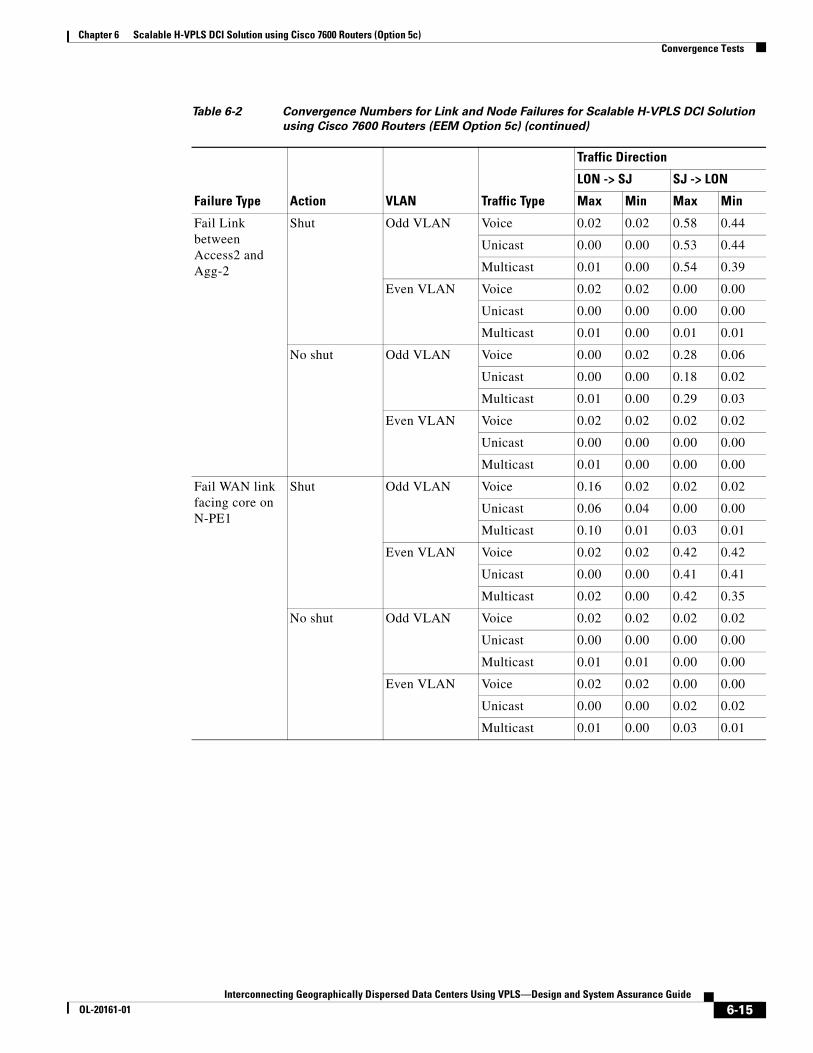
Chapter 6 Scalable H-VPLS DCI Solution using Cisco 7600 Routers (Option 5c)Convergence Tests
Fail Link between Access2 and Agg-2
Shut Odd VLAN Voice 0.02 0.02 0.58 0.44
Unicast 0.00 0.00 0.53 0.44
Multicast 0.01 0.00 0.54 0.39
Even VLAN Voice 0.02 0.02 0.00 0.00
Unicast 0.00 0.00 0.00 0.00
Multicast 0.01 0.00 0.01 0.01
No shut Odd VLAN Voice 0.00 0.02 0.28 0.06
Unicast 0.00 0.00 0.18 0.02
Multicast 0.01 0.00 0.29 0.03
Even VLAN Voice 0.02 0.02 0.02 0.02
Unicast 0.00 0.00 0.00 0.00
Multicast 0.01 0.00 0.00 0.00
Fail WAN link facing core on N-PE1
Shut Odd VLAN Voice 0.16 0.02 0.02 0.02
Unicast 0.06 0.04 0.00 0.00
Multicast 0.10 0.01 0.03 0.01
Even VLAN Voice 0.02 0.02 0.42 0.42
Unicast 0.00 0.00 0.41 0.41
Multicast 0.02 0.00 0.42 0.35
No shut Odd VLAN Voice 0.02 0.02 0.02 0.02
Unicast 0.00 0.00 0.00 0.00
Multicast 0.01 0.01 0.00 0.00
Even VLAN Voice 0.02 0.02 0.00 0.00
Unicast 0.00 0.00 0.02 0.02
Multicast 0.01 0.00 0.03 0.01
Table 6-2 Convergence Numbers for Link and Node Failures for Scalable H-VPLS DCI Solution
using Cisco 7600 Routers (EEM Option 5c) (continued)
Failure Type Action VLAN Traffic Type
Traffic Direction
LON -> SJ SJ -> LON
Max Min Max Min
6-15Interconnecting Geographically Dispersed Data Centers Using VPLS—Design and System Assurance Guide
OL-20161-01

Chapter 6 Scalable H-VPLS DCI Solution using Cisco 7600 Routers (Option 5c)Convergence Tests
Fail WAN link facing core on N-PE2
Shut Odd VLAN Voice 0.24 0.20 0.06 0.06
Unicast 0.21 0.21 0.06 0.05
Multicast 0.23 0.20 0.06 0.06
Even VLAN Voice 0.02 0.02 0.00 0.00
Unicast 0.00 0.00 0.00 0.00
Multicast 0.00 0.00 0.00 0.00
No shut Odd VLAN Voice 0.04 0.02 0.02 0.02
Unicast 0.03 0.03 0.00 0.00
Multicast 0.04 0.02 0.01 0.01
Even VLAN Voice 0.02 0.02 0.02 0.02
Unicast 0.00 0.00 0.00 0.00
Multicast 0.01 0.00 0.01 0.01
Fail both WAN links on N-PE1
Shut Odd VLAN Voice 0.02 0.02 0.00 0.00
Unicast 0.00 0.00 0.00 0.00
Multicast 0.01 0.00 0.01 0.01
Even VLAN Voice 0.26 0.24 0.02 0.02
Unicast 0.25 0.25 0.02 0.02
Multicast 0.26 0.25 0.03 0.03
No shut Odd VLAN Voice 0.02 0.02 0.02 0.02
Unicast 0.00 0.00 0.00 0.00
Multicast 0.01 0.00 0.00 0.00
Even VLAN Voice 0.02 0.02 0.02 0.02
Unicast 0.01 0.01 0.00 0.00
Multicast 0.01 0.00 0.00 0.00
Table 6-2 Convergence Numbers for Link and Node Failures for Scalable H-VPLS DCI Solution
using Cisco 7600 Routers (EEM Option 5c) (continued)
Failure Type Action VLAN Traffic Type
Traffic Direction
LON -> SJ SJ -> LON
Max Min Max Min
6-16Interconnecting Geographically Dispersed Data Centers Using VPLS—Design and System Assurance Guide
OL-20161-01

Chapter 6 Scalable H-VPLS DCI Solution using Cisco 7600 Routers (Option 5c)Convergence Tests
Fail both WAN links on N-PE2
Shut Odd VLAN Voice 0.54 0.02 0.46 0.46
Unicast 0.51 0.51 0.44 0.44
Multicast 2.23 0.66 0.45 0.45
Even VLAN Voice 0.02 0.02 0.02 0.02
Unicast 0.00 0.00 0.00 0.00
Multicast 0.01 0.00 0.01 0.01
No shut Odd VLAN Voice 1.36 1.31 1.32 1.32
Unicast 1.33 1.32 1.32 1.32
Multicast 2.44 1.92 1.33 1.33
Even VLAN Voice 0.02 0.02 0.00 0.00
Unicast 0.00 0.00 0.00 0.00
Multicast 0.01 0.00 0.01 0.01
Clear dynamic MAC address table on aggregation switches
Clear Odd VLAN Voice 0.06 0.02 0.02 0.02
Unicast 0.01 0.01 0.00 0.00
Multicast 0.04 0.00 0.00 0.00
Even VLAN Voice 0.71 0.67 0.54 0.54
Unicast 0.69 0.69 0.53 0.53
Multicast 2.50 1.09 0.54 0.52
Clear IP routing table on both N-PEs
Clear Odd VLAN Voice 0.04 0.02 0.00 0.00
Unicast 0.02 0.01 0.00 0.00
Multicast 0.05 0.01 0.00 0.00
Even VLAN Voice 0.74 0.70 0.72 0.72
Unicast 0.71 0.71 0.71 0.71
Multicast 2.05 0.81 0.71 0.71
Clear dynamic MAC address table on both N-PEs
Clear Odd VLAN Voice 0.02 0.00 0.00 0.00
Unicast 0.00 0.00 0.00 0.00
Multicast 0.01 0.00 0.00 0.00
Even VLAN Voice 0.02 0.00 0.00 0.00
Unicast 0.00 0.00 0.00 0.00
Multicast 0.02 0.00 0.00 0.00
Table 6-2 Convergence Numbers for Link and Node Failures for Scalable H-VPLS DCI Solution
using Cisco 7600 Routers (EEM Option 5c) (continued)
Failure Type Action VLAN Traffic Type
Traffic Direction
LON -> SJ SJ -> LON
Max Min Max Min
6-17Interconnecting Geographically Dispersed Data Centers Using VPLS—Design and System Assurance Guide
OL-20161-01

Chapter 6 Scalable H-VPLS DCI Solution using Cisco 7600 Routers (Option 5c)Convergence Tests
6-18Interconnecting Geographically Dispersed Data Centers Using VPLS—Design and System Assurance Guide
OL-20161-01

Interconnecting Geographically Dispersed Data CentersOL-20161-01
C H A P T E R 7
VPLSoGRE DCI Solution using Cisco Catalyst 6500 (VPLSoGRE Option 4a)Typically, EoMPLS and VPLS technologies have required MPLS switching core for Layer 2 extension over long distances. When the core network is not dedicated for L2VPN extension, migrating an existing IP core to MPLS can be complex. Also, MPLS and its related technologies require expertise for deployment and maintenance. To ease the adoption of Layer 2 extension, Cisco Systems offers solutions to encapsulate EoMPLS or VPLS traffic over GRE tunnels. These solutions allow transporting all Layer 2 traffic across data centers over the existing IP core. EoMPLS / VPLS over GRE also is known as Any Transport over MPLS over GRE (AToMoGRE) or Layer 2 Virtual Private Network over Generic Routing Encapsulation (L2VPNoGRE).
GRE-based deployment models focus on using L2VPN over an IP core network, which eliminates MPLS switching in the core. These deployment models provide Layer 2 extension over a WAN and take advantage of Layer 3 fast convergence and EEM to interconnect geographically dispersed data centers.
Cisco Catalyst 6500 series switches with a SIP-400 module running Cisco IOS Software Release 12.2(33)SXI or later support multipoint bridging using VPLSoGRE over an IP network with STP isolation.
This chapter includes these topics:
• Overview, page 7-1
• Configuration Summary, page 7-2
• Convergence Tests, page 7-8
• Cluster Server Tests, page 7-11
OverviewIn VPLSoGRE, IP GRE tunnels are established between the core routers within each data center. MPLS LDP sessions are established through these GRE tunnels, which provide MPLS connectivity. MPLS connectivity over GRE tunnels is known as MPLSoGRE. VPLS virtual circuits are then established over MPLSoGRE tunnels, which provide multipoint connectivity over an IP network.
Figure 7-1 shows VPLS connectivity across an IP network.
7-1 Using VPLS—Design and System Assurance Guide

Chapter 7 VPLSoGRE DCI Solution using Cisco Catalyst 6500 (VPLSoGRE Option 4a)Configuration Summary
Figure 7-1 VPLSoGRE using Cisco Catalyst 6500
Configuration SummaryThis section describes the key configuration differences between VPLSoGRE and EEM option 5c.
• Create GRE tunnels between N-PEs and enable MPLS on these GRE tunnels. Ensure that the tunnel destination is reachable via a Gigabit Ethernet interface on the SIP-400 module. The following shows the configuration for N-PE1:
lon-n-pe1-cat6500#!interface Loopback1 description tunnel source for VPLSoGRE ip address 99.1.1.11 255.255.255.255!interface Loopback2 description tunnel source for VPLSoGRE ip address 99.1.1.13 255.255.255.255!interface Loopback3 description tunnel source for VPLSoGRE ip address 99.1.1.15 255.255.255.255!interface Loopback4 description tunnel source for VPLSoGRE ip address 99.1.1.17 255.255.255.255!interface Tunnel1121 description to sin-n-pe1 Tunnel2111 ip address 200.1.1.1 255.255.255.252 ip ospf network point-to-point
7-2Interconnecting Geographically Dispersed Data Centers Using VPLS—Design and System Assurance Guide
OL-20161-01

Chapter 7 VPLSoGRE DCI Solution using Cisco Catalyst 6500 (VPLSoGRE Option 4a)Configuration Summary
mpls ip tunnel source 99.1.1.15 tunnel destination 99.1.1.21!interface Tunnel1122 description to sin-n-pe2 tunn2211 ip address 200.1.2.1 255.255.255.252 ip ospf network point-to-point mpls ip tunnel source 99.1.1.17 tunnel destination 99.1.1.22!interface Tunnel1131 description to sj-n-pe1 Tunnel3111 ip address 200.1.3.1 255.255.255.252 ip ospf network point-to-point mpls ip tunnel source 99.1.1.11 tunnel destination 99.1.1.31!interface Tunnel1132 description to sj-n-pe2 Tunnel3211 ip address 200.1.4.1 255.255.255.252 ip ospf network point-to-point mpls ip tunnel source 99.1.1.13 tunnel destination 99.1.1.32
• MPLS LDP neighbors should be reachable via GRE tunnels. Configure static routes to reach the LDP neighbors via the tunnels configured in step 1. The following shows the configuration for N-PE1:
lon-n-pe1-cat6500#!! Tunnels for LDP peering with N-PEs in remote data centersip route 10.76.70.21 255.255.255.255 Tunnel1121ip route 10.76.70.22 255.255.255.255 Tunnel1122ip route 10.76.70.31 255.255.255.255 Tunnel1131ip route 10.76.70.32 255.255.255.255 Tunnel1132!! Tunnels to enable backup PWs for even VLANs to N-PE2's in remote data centersip route 10.76.90.22 255.255.255.255 Tunnel1122ip route 10.76.90.32 255.255.255.255 Tunnel1132!! Tunnels to enable primary PWs for odd VLANs on N-PE1's in remote data centersip route 10.76.91.21 255.255.255.255 Tunnel1121ip route 10.76.91.31 255.255.255.255 Tunnel1131!! Tunnels to enable backup PWs for odd VLANs on N-PE2's in remote data centersip route 10.76.91.22 255.255.255.255 Tunnel1122ip route 10.76.91.32 255.255.255.255 Tunnel1132
• Verify that OSPF neighbors and LDP peers are established via these GRE tunnels:
lon-n-pe1-cat6500#sh ip route 99.1.1.31
Routing entry for 99.1.1.31/32 Known via "ospf 1", distance 110, metric 14, type intra area Last update from 192.168.41.12 on GigabitEthernet3/0/0, 00:05:18 ago Routing Descriptor Blocks: * 192.168.41.12, from 31.31.31.31, 00:05:18 ago, via GigabitEthernet3/0/0 Route metric is 14, traffic share count is 1 lon-n-pe1-cat6500#show ip route 10.76.70.31
7-3Interconnecting Geographically Dispersed Data Centers Using VPLS—Design and System Assurance Guide
OL-20161-01

Chapter 7 VPLSoGRE DCI Solution using Cisco Catalyst 6500 (VPLSoGRE Option 4a)Configuration Summary
Routing entry for 10.76.70.31/32 Known via "static", distance 1, metric 0 (connected) Routing Descriptor Blocks: * directly connected, via Tunnel1131 Route metric is 0, traffic share count is 1
lon-n-pe1-cat6500#show ip ospf neighbor
Neighbor ID Pri State Dead Time Address Interface99.1.1.38 0 FULL/ - 00:00:33 200.1.4.2 Tunnel113299.1.1.37 0 FULL/ - 00:00:33 200.1.3.2 Tunnel113199.1.1.28 0 FULL/ - 00:00:32 200.1.2.2 Tunnel112299.1.1.27 0 FULL/ - 00:00:33 200.1.1.2 Tunnel1121116.5.200.77 0 FULL/ - 00:00:37 192.168.41.12 GigabitEthernet3/0/012.12.12.12 0 FULL/ - 00:00:39 192.168.13.2 GigabitEthernet3/0/113.13.13.13 0 FULL/ - 00:00:33 10.11.11.2 GigabitEthernet2/8
lon-n-pe1-cat6500#show cdp neighborsCapability Codes: R - Router, T - Trans Bridge, B - Source Route Bridge S - Switch, H - Host, I - IGMP, r - Repeater, P - Phone
Device ID Local Intrfce Holdtme Capability Platform Port IDlon-agg-1 Gig 2/7 179 R S I WS-C6509- Gig 2/3lon-core1 Gig 2/8 159 R S I WS-C6506 Gig 3/8mpls-p1 Gig 3/0/0 140 R S I WS-C6506 Gig 5/1lon-n-pe2-cat6500 Gig 3/0/1 155 R S I WS-C6506- Gig 3/0/1lon-n-pe2-cat6500 Gig 2/2 146 R S I WS-C6506- Gig 2/2lon-n-pe2-cat6500 Gig 2/1 133 R S I WS-C6506- Gig 2/1
lon-n-pe1-cat6500#
• For one VFI per group of VLANs to be transported across data centers, create QinQ VLANs on both N-PEs. Configure QinQ using dot1q-tunnel on the Q-links between N-PEs and aggregation switches.
Note The Cisco Catalyst 6500 does not support selective QinQ. Two physical links were provisioned between N-PEs and aggregation switches to load-balance traffic between odd and even VLANs.
7-4Interconnecting Geographically Dispersed Data Centers Using VPLS—Design and System Assurance Guide
OL-20161-01

Chapter 7 VPLSoGRE DCI Solution using Cisco Catalyst 6500 (VPLSoGRE Option 4a)Configuration Summary
Create one VFI per QinQ VLAN to be connected to other data centers and create one switched virtual interface (SVI) per QinQ VLAN as shown here for N-PE1 and N-PE2:
On N-PE1vlan 4001name H-VPLS_Primary_core_VLAN_for_odd_vlansvlan 4004name H-VPLS_Backup_core_VLAN_for_even_vlans!interface GigabitEthernet2/5 description QinQ link for Odd Vlans - connected to LON-Agg-1 switchport switchport access vlan 4001 switchport trunk allowed vlan 1,3,5,7,9,11 .. switchport mode dot1q-tunnel mtu 9216 spanning-tree bpdufilter enable!interface GigabitEthernet2/6 description QonQ link for Even Vlans -connected to LON-Agg-1 switchport switchport access vlan 4004 switchport trunk allowed vlan 2,4,6,8,10,12 .. switchport mode dot1q-tunnel mtu 9216 spanning-tree bpdufilter enable!end
On N-PE2vlan 4004name H-VPLS_Primary_core_VLAN_for_even_vlansvlan 4001name H-VPLS_Backup_core_VLAN_for_odd_vlans!interface GigabitEthernet2/5 description QinQ link for Even Vlans connected to LON-Agg-2 switchport switchport access vlan 4004 switchport trunk allowed vlan 2,4,6,8,10 .. switchport mode dot1q-tunnel mtu 9216 spanning-tree bpdufilter enable!interface GigabitEthernet2/6 description QinQ link for Odd Vlans connected to LON-Agg-2. switchport switchport access vlan 4001 switchport trunk allowed vlan 1,3,5,7,9,11 .. switchport mode dot1q-tunnel mtu 9216 spanning-tree bpdufilter enable!end
On Agg-1interface GigabitEthernet2/2 description Odd-Vlans QinQ Link to lon-n-pe1-cat6500 g2/5 switchport switchport trunk encapsulation dot1q switchport trunk allowed vlan 1,3,5,7,9,11 .. switchport mode trunk mtu 9216 spanning-tree portfast trunk spanning-tree bpdufilter enable!interface GigabitEthernet2/4 description Even Vlans QinQ link to lon-n-pe1-cat6500 g2/6 switchport switchport trunk encapsulation dot1q switchport trunk allowed vlan 2,4,6,8,10,12 .. switchport mode trunk mtu 9216 spanning-tree portfast trunk spanning-tree bpdufilter enableend
On Agg-2interface GigabitEthernet2/2 description Even-Vlans QinQ Link to lon-n-pe2-cat6500 gi2/5 switchport switchport trunk encapsulation dot1q switchport trunk allowed vlan 2,4,6,8,10,12 .. switchport mode trunk mtu 9216 spanning-tree portfast trunk spanning-tree bpdufilter enable!interface GigabitEthernet2/4 description Odd-Vlans QiQ Link to lon-n-pe2-cat6500 g2/6 switchport switchport trunk encapsulation dot1q switchport trunk allowed vlan 1,3,5,7,9,11 .. switchport mode trunk mtu 9216 spanning-tree portfast trunk spanning-tree bpdufilter enableend
7-5Interconnecting Geographically Dispersed Data Centers Using VPLS—Design and System Assurance Guide
OL-20161-01

Chapter 7 VPLSoGRE DCI Solution using Cisco Catalyst 6500 (VPLSoGRE Option 4a)Configuration Summary
On N-PE1lon-n-pe1-cat6500#!l2 vfi VFI-4001 manual vpn id 4001 neighbor 10.76.91.31 encapsulation mpls neighbor 10.76.91.22 encapsulation mpls neighbor 10.76.91.21 encapsulation mpls neighbor 10.76.91.32 encapsulation mpls!l2 vfi VFI-4004 manual vpn id 4004 neighbor 10.76.90.22 encapsulation mpls neighbor 10.76.90.32 encapsulation mpls
lon-n-pe1-cat6500#...!mpls ldp neighbor 10.76.70.12 targeted ldpmpls ldp neighbor 10.76.70.21 targeted ldpmpls ldp neighbor 10.76.70.22 targeted ldpmpls ldp neighbor 10.76.70.31 targeted ldpmpls ldp neighbor 10.76.70.32 targeted ldpmpls ldp tcp pak-prioritympls ldp session protectionno mpls ldp advertise-labelsmpls ldp advertise-labels for 76mpls label protocol ldpxconnect logging pseudowire status!access-list 76 permit 10.76.0.0 0.0.255.255!lon-n-pe1-cat6500#
lon-n-pe1-cat6500#!interface Vlan4001 description Primary Core QinQ VLAN - used to transport Odd edge VLAN mtu 9216 no ip address xconnect vfi VFI-4001!interface Vlan4004 description Backup Core QinQ VLAN - used to transport Even edge VLAN mtu 9216 no ip address xconnect vfi VFI-4004
lon-n-pe1-cat6500#show mpls l2 vc
Local intf Local circuit Dest address VC ID Status ------------- -------------------------- --------------- ---------- ----------VFI VFI-4004 VFI 10.76.90.22 4004 DOWN VFI VFI-4004 VFI 10.76.90.32 4004 DOWN VFI VFI-4001 VFI 10.76.91.21 4001 UP VFI VFI-4001 VFI 10.76.91.22 4001 DOWN VFI VFI-4001 VFI 10.76.91.31 4001 UP VFI VFI-4001 VFI 10.76.91.32 4001 DOWN
lon-n-pe1-cat6500#
7-6Interconnecting Geographically Dispersed Data Centers Using VPLS—Design and System Assurance Guide
OL-20161-01

Chapter 7 VPLSoGRE DCI Solution using Cisco Catalyst 6500 (VPLSoGRE Option 4a)Configuration Summary
On N-PE2lon-n-pe2-cat6500#!l2 vfi VFI-4001 manual vpn id 4001 neighbor 10.76.91.31 encapsulation mpls neighbor 10.76.91.21 encapsulation mpls!l2 vfi VFI-4004 manual vpn id 4004 neighbor 10.76.90.22 encapsulation mpls neighbor 10.76.90.21 encapsulation mpls neighbor 10.76.90.32 encapsulation mpls neighbor 10.76.90.31 encapsulation mpls
lon-n-pe2-cat6500#...!mpls ldp neighbor 10.76.70.11 targeted ldpmpls ldp neighbor 10.76.70.21 targeted ldpmpls ldp neighbor 10.76.70.22 targeted ldpmpls ldp neighbor 10.76.70.31 targeted ldpmpls ldp neighbor 10.76.70.32 targeted ldpmpls ldp tcp pak-prioritympls ldp session protectionno mpls ldp advertise-labelsmpls ldp advertise-labels for 76mpls label protocol ldpxconnect logging pseudowire status!access-list 76 permit 10.76.0.0 0.0.255.255!lon-n-pe2-cat6500#
lon-n-pe2-cat6500#!interface Vlan4004 description Primary Core QinQ VLAN - used to transport Even edge VLAN mtu 9216 no ip address xconnect vfi VFI-4004!interface Vlan4001description Backup Core QinQ VLAN - used to transport odd edge VLANmtu 9216 no ip address xconnect vfi VFI-4001
lon-n-pe2-cat6500#show mpls l2 vc
Local intf Local circuit Dest address VC ID Status ------------- -------------------------- --------------- ---------- ----------VFI VFI-4004 VFI 10.76.90.21 4004 DOWN VFI VFI-4004 VFI 10.76.90.22 4004 UP VFI VFI-4004 VFI 10.76.90.31 4004 DOWN VFI VFI-4004 VFI 10.76.90.32 4004 UP VFI VFI-4001 VFI 10.76.91.21 4001 DOWN VFI VFI-4001 VFI 10.76.91.31 4001 DOWN
lon-n-pe2-cat6500#
7-7Interconnecting Geographically Dispersed Data Centers Using VPLS—Design and System Assurance Guide
OL-20161-01

Chapter 7 VPLSoGRE DCI Solution using Cisco Catalyst 6500 (VPLSoGRE Option 4a)Convergence Tests
Convergence TestsThe traffic profile outlined in the “Traffic Profile” section on page 4-6 was used to determine end-to-end convergence for unidirectional voice, unicast, and multicast traffic. Links and nodes were failed to simulate network failures.
Table 7-1 shows results of various node and link failures for the VPLSoGRE with N-PE redundancy using EEM semaphore solution. Convergence numbers (max and min) are in seconds
Table 7-1 Convergence Numbers for VPLSoGRE DCI Solution using Cisco Catalyst 6500
Traffic Direction
LON -> SJ SJ -> LON
Failure Type Action VLAN Traffic Type Max Min Max Min
Reload N-PE1 Reload Odd VLAN Voice 2.46 0.02 2.62 2.62
Unicast 2.43 2.43 2.62 2.62
Even VLAN Voice 0.02 0.02 0.02 0.02
Unicast 0.00 0.00 0.00 0.00
Restore Odd VLAN Voice 0.90 0.88 0.88 0.88
Unicast 0.89 0.89 0.87 0.87
Even VLAN Voice 0.00 0.00 0.00 0.00
Unicast 0.00 0.00 0.00 0.00
Reload N-PE2 Reload Odd VLAN Voice 0.02 0.00 0.02 0.02
Unicast 0.00 0.00 0.00 0.00
Even VLAN Voice 1.40 1.38 1.36 1.36
Unicast 1.38 1.38 1.36 1.36
Restore Odd VLAN Voice 0.02 0.02 0.02 0.02
Unicast 0.00 0.00 0.00 0.00
Even VLAN Voice 0.58 0.56 0.55 0.55
Unicast 0.57 0.57 0.55 0.55
Reload Agg-1 Reload Odd VLAN Voice 5.56 5.54 3.58 3.58
Unicast 5.55 5.55 3.58 3.58
Even VLAN Voice 0.02 0.02 0.00 0.00
Unicast 0.06 0.00 0.05 0.01
Restore Odd VLAN Voice 0.62 0.02 0.86 0.64
Unicast 0.61 0.61 0.86 0.64
Even VLAN Voice 0.00 0.00 0.00 0.00
Unicast 0.00 0.00 0.00 0.00
7-8Interconnecting Geographically Dispersed Data Centers Using VPLS—Design and System Assurance Guide
OL-20161-01

Chapter 7 VPLSoGRE DCI Solution using Cisco Catalyst 6500 (VPLSoGRE Option 4a)Convergence Tests
Reload Agg-2 Reload Odd VLAN Voice 0.02 0.02 0.00 0.00
Unicast 0.00 0.00 0.00 0.00
Even VLAN Voice 2.14 2.12 2.12 2.12
Unicast 2.13 2.13 2.13 2.13
Restore Odd VLAN Voice 0.00 0.00 0.00 0.00
Unicast 0.00 0.00 0.00 0.00
Even VLAN Voice 1.18 1.10 1.50 1.50
Unicast 1.17 1.12 1.50 1.12
Fail L2 link between N-PE1 and Agg-1
Shut Odd VLAN Voice 2.68 2.65 2.64 2.62
Unicast 2.68 2.68 2.64 2.61
Even VLAN Voice 0.02 0.02 0.00 0.00
Unicast 0.00 0.00 0.00 0.00
No shut Odd VLAN Voice 1.44 1.44 1.44 1.44
Unicast 1.44 1.44 1.42 1.42
Even VLAN Voice 0.02 0.02 0.02 0.02
Unicast 0.00 0.00 0.00 0.00
Fail L2 link between N-PE2 and Agg-2
Shut Odd VLAN Voice 0.00 0.00 0.02 0.02
Unicast 0.00 0.00 0.00 0.00
Even VLAN Voice 2.26 2.24 2.30 2.30
Unicast 2.26 2.26 2.28 2.27
No shut Odd VLAN Voice 0.02 0.02 0.02 0.02
Unicast 0.00 0.00 0.00 0.00
Even VLAN Voice 1.10 1.08 1.10 1.10
Unicast 1.09 1.09 1.07 1.07
Fail L2 link between Agg-1 and Agg-2
Shut Odd VLAN Voice 0.02 0.02 0.02 0.02
Unicast 0.00 0.00 0.00 0.00
Even VLAN Voice 0.02 0.02 0.02 0.02
Unicast 0.00 0.00 0.00 0.00
No shut Odd VLAN Voice 0.02 0.02 0.00 0.00
Unicast 0.00 0.00 0.00 0.00
Even VLAN Voice 0.02 0.00 0.00 0.00
Unicast 0.00 0.00 0.00 0.00
Table 7-1 Convergence Numbers for VPLSoGRE DCI Solution using Cisco Catalyst 6500 (continued)
Traffic Direction
LON -> SJ SJ -> LON
Failure Type Action VLAN Traffic Type Max Min Max Min
7-9Interconnecting Geographically Dispersed Data Centers Using VPLS—Design and System Assurance Guide
OL-20161-01

Chapter 7 VPLSoGRE DCI Solution using Cisco Catalyst 6500 (VPLSoGRE Option 4a)Convergence Tests
Fail WAN link facing core on N-PE1
Shut Odd VLAN Voice 1.18 1.14 0.00 0.00
Unicast 1.16 1.16 0.00 0.00
Even VLAN Voice 0.00 0.00 0.00 0.00
Unicast 0.00 0.00 0.00 0.00
No shut Odd VLAN Voice 0.00 0.00 0.00 0.00
Unicast 0.00 0.00 0.00 0.00
Even VLAN Voice 0.02 0.00 0.00 0.00
Unicast 0.00 0.00 0.00 0.00
Fail WAN link facing core on N-PE2
Shut Odd VLAN Voice 0.00 0.00 0.00 0.00
Unicast 0.03 0.00 0.00 0.00
Even VLAN Voice 1.02 1.00 0.00 0.00
Unicast 1.00 1.00 0.00 0.00
No shut Odd VLAN Voice 0.00 0.00 0.02 0.02
Unicast 0.00 0.00 0.00 0.00
Even VLAN Voice 0.02 0.02 0.02 0.02
Unicast 0.00 0.00 0.00 0.00
Fail both WAN links on N-PE1
Shut Odd VLAN Voice 1.76 1.74 1.84 1.84
Unicast 1.74 1.74 1.80 1.80
Even VLAN Voice 0.02 0.02 0.04 0.04
Unicast 0.00 0.00 0.00 0.00
No shut Odd VLAN Voice 0.50 0.48 0.52 0.52
Unicast 0.48 0.47 0.48 0.47
Even VLAN Voice 0.02 0.02 0.04 0.04
Unicast 0.00 0.00 0.00 0.00
Fail both WAN links on N-PE2
Shut Odd VLAN Voice 0.02 0.02 0.04 0.04
Unicast 0.00 0.00 0.00 0.00
Even VLAN Voice 1.39 1.36 1.64 1.64
Unicast 1.37 1.37 1.60 1.60
No shut Odd VLAN Voice 0.02 0.02 0.02 0.02
Unicast 0.00 0.00 0.00 0.00
Even VLAN Voice 0.40 0.36 0.42 0.42
Unicast 0.38 0.38 0.41 0.41
Table 7-1 Convergence Numbers for VPLSoGRE DCI Solution using Cisco Catalyst 6500 (continued)
Traffic Direction
LON -> SJ SJ -> LON
Failure Type Action VLAN Traffic Type Max Min Max Min
7-10Interconnecting Geographically Dispersed Data Centers Using VPLS—Design and System Assurance Guide
OL-20161-01

Chapter 7 VPLSoGRE DCI Solution using Cisco Catalyst 6500 (VPLSoGRE Option 4a)Cluster Server Tests
Cluster Server TestsTable 7-2 shows event logs from the event viewer of Microsoft cluster server. Event logs were captured from the event viewer of Microsoft cluster server. The logs are in the reverse order, showing the last event, first. It is best to view the timestamps while analyzing these logs.
Table 10-2Event Logs for the VPLSoGRE with N-PE Redundancy Using EEM Semaphore Solution
Clear entire routing table on both N-PEs
Clear Odd VLAN Voice 5.02 4.98 4.98 4.98
Unicast 4.99 4.98 4.96 4.96
Even VLAN Voice 0.02 0.02 0.02 0.02
Unicast 0.00 0.00 0.00 0.00
Clear dynamic MAC address table on both N-PEs
Clear Odd VLAN Voice 0.02 0.02 0.00 0.00
Unicast 0.00 0.00 0.00 0.00
Even VLAN Voice 0.00 0.00 0.00 0.00
Unicast 0.00 0.00 0.00 0.00
Table 7-1 Convergence Numbers for VPLSoGRE DCI Solution using Cisco Catalyst 6500 (continued)
Traffic Direction
LON -> SJ SJ -> LON
Failure Type Action VLAN Traffic Type Max Min Max Min
7-11Interconnecting Geographically Dispersed Data Centers Using VPLS—Design and System Assurance Guide
OL-20161-01
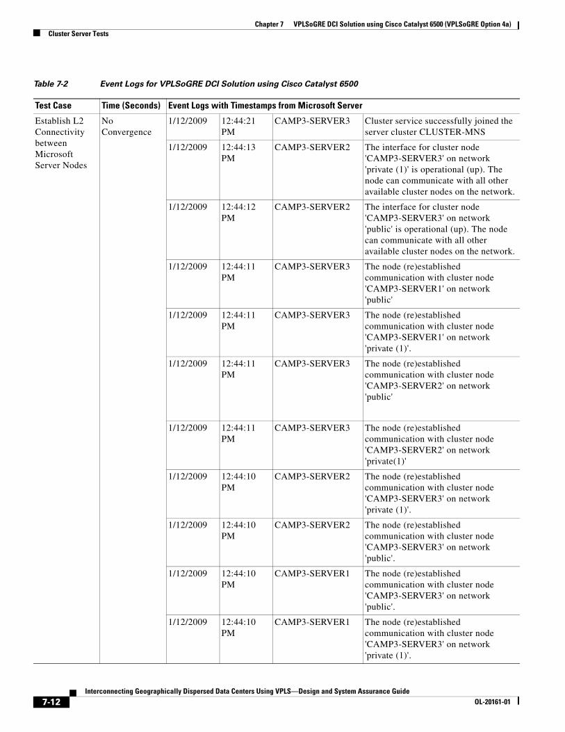
Chapter 7 VPLSoGRE DCI Solution using Cisco Catalyst 6500 (VPLSoGRE Option 4a)Cluster Server Tests
Table 7-2 Event Logs for VPLSoGRE DCI Solution using Cisco Catalyst 6500
Test Case Time (Seconds) Event Logs with Timestamps from Microsoft Server
Establish L2 Connectivity between Microsoft Server Nodes
No Convergence
1/12/2009 12:44:21 PM
CAMP3-SERVER3 Cluster service successfully joined the server cluster CLUSTER-MNS
1/12/2009 12:44:13 PM
CAMP3-SERVER2 The interface for cluster node 'CAMP3-SERVER3' on network 'private (1)' is operational (up). The node can communicate with all other available cluster nodes on the network.
1/12/2009 12:44:12 PM
CAMP3-SERVER2 The interface for cluster node 'CAMP3-SERVER3' on network 'public' is operational (up). The node can communicate with all other available cluster nodes on the network.
1/12/2009 12:44:11 PM
CAMP3-SERVER3 The node (re)established communication with cluster node 'CAMP3-SERVER1' on network 'public'
1/12/2009 12:44:11 PM
CAMP3-SERVER3 The node (re)established communication with cluster node 'CAMP3-SERVER1' on network 'private (1)'.
1/12/2009 12:44:11 PM
CAMP3-SERVER3 The node (re)established communication with cluster node 'CAMP3-SERVER2' on network 'public'
1/12/2009 12:44:11 PM
CAMP3-SERVER3 The node (re)established communication with cluster node 'CAMP3-SERVER2' on network 'private(1)'
1/12/2009 12:44:10 PM
CAMP3-SERVER2 The node (re)established communication with cluster node 'CAMP3-SERVER3' on network 'private (1)'.
1/12/2009 12:44:10 PM
CAMP3-SERVER2 The node (re)established communication with cluster node 'CAMP3-SERVER3' on network 'public'.
1/12/2009 12:44:10 PM
CAMP3-SERVER1 The node (re)established communication with cluster node 'CAMP3-SERVER3' on network 'public'.
1/12/2009 12:44:10 PM
CAMP3-SERVER1 The node (re)established communication with cluster node 'CAMP3-SERVER3' on network 'private (1)'.
7-12Interconnecting Geographically Dispersed Data Centers Using VPLS—Design and System Assurance Guide
OL-20161-01
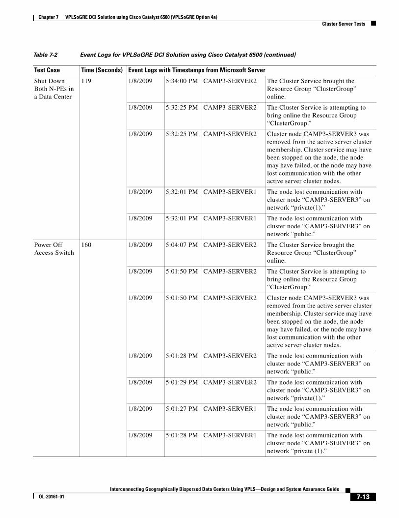
Chapter 7 VPLSoGRE DCI Solution using Cisco Catalyst 6500 (VPLSoGRE Option 4a)Cluster Server Tests
Shut Down Both N-PEs in a Data Center
119 1/8/2009 5:34:00 PM CAMP3-SERVER2 The Cluster Service brought the Resource Group “ClusterGroup” online.
1/8/2009 5:32:25 PM CAMP3-SERVER2 The Cluster Service is attempting to bring online the Resource Group “ClusterGroup.”
1/8/2009 5:32:25 PM CAMP3-SERVER2 Cluster node CAMP3-SERVER3 was removed from the active server cluster membership. Cluster service may have been stopped on the node, the node may have failed, or the node may have lost communication with the other active server cluster nodes.
1/8/2009 5:32:01 PM CAMP3-SERVER1 The node lost communication with cluster node “CAMP3-SERVER3” on network “private(1).”
1/8/2009 5:32:01 PM CAMP3-SERVER1 The node lost communication with cluster node “CAMP3-SERVER3” on network “public.”
Power Off Access Switch
160 1/8/2009 5:04:07 PM CAMP3-SERVER2 The Cluster Service brought the Resource Group “ClusterGroup” online.
1/8/2009 5:01:50 PM CAMP3-SERVER2 The Cluster Service is attempting to bring online the Resource Group “ClusterGroup.”
1/8/2009 5:01:50 PM CAMP3-SERVER2 Cluster node CAMP3-SERVER3 was removed from the active server cluster membership. Cluster service may have been stopped on the node, the node may have failed, or the node may have lost communication with the other active server cluster nodes.
1/8/2009 5:01:28 PM CAMP3-SERVER2 The node lost communication with cluster node “CAMP3-SERVER3” on network “public.”
1/8/2009 5:01:29 PM CAMP3-SERVER2 The node lost communication with cluster node “CAMP3-SERVER3” on network “private(1).”
1/8/2009 5:01:27 PM CAMP3-SERVER1 The node lost communication with cluster node “CAMP3-SERVER3” on network “public.”
1/8/2009 5:01:28 PM CAMP3-SERVER1 The node lost communication with cluster node “CAMP3-SERVER3” on network “private (1).”
Table 7-2 Event Logs for VPLSoGRE DCI Solution using Cisco Catalyst 6500 (continued)
Test Case Time (Seconds) Event Logs with Timestamps from Microsoft Server
7-13Interconnecting Geographically Dispersed Data Centers Using VPLS—Design and System Assurance Guide
OL-20161-01

Chapter 7 VPLSoGRE DCI Solution using Cisco Catalyst 6500 (VPLSoGRE Option 4a)Cluster Server Tests
Shut Down Active Node
103 1/8/2009 6:25:40 PM CAMP3-SERVER2 The Cluster Service brought the Resource Group “ClusterGroup” online.
1/8/2009 6:24:36 PM CAMP3-SERVER3 Cluster service is attempting to failover the Cluster Resource Group “ClusterGroup” from node CAMP3-SERVER3 to node CAMP3-SERVER2.
1/8/2009 6:24:17 PM CAMP3-SERVER2 The Cluster Service is attempting to bring online the Resource Group “ClusterGroup.”
1/8/2009 6:23:56 PM CAMP3-SERVER2 The node lost communication with cluster node “CAMP3-SERVER3” on network “public.”
1/8/2009 6:23:57 PM CAMP3-SERVER1 The node lost communication with cluster node “CAMP3-SERVER3” on network “public.”
Private VLAN NPE Reload
4 1/8/2009 5:51:27 PM CAMP3-SERVER3 The node (re)established communication with cluster node “CAMP3-SERVER1” on network “private(1).”
1/8/2009 5:51:27 PM CAMP3-SERVER1 The node (re)established communication with cluster node “CAMP3-SERVER3” on network “private(1).”
1/8/2009 5:51:27 PM CAMP3-SERVER2 The node (re)established communication with cluster node “CAMP3-SERVER3” on network “private(1).”
1/8/2009 5:51:26 PM CAMP3-SERVER3 The node (re)established communication with cluster node “CAMP3-SERVER2” on network “private(1).”
1/8/2009 5:51:24 PM CAMP3-SERVER3 The node lost communication with cluster node “CAMP3-SERVER1” on network “private(1).”
1/8/2009 5:51:24 PM CAMP3-SERVER3 The node lost communication with cluster node “CAMP3-SERVER2” on network “private(1).”
1/8/2009 5:51:24 PM CAMP3-SERVER1 The node lost communication with cluster node “CAMP3-SERVER3” on network “private(1).”
1/8/2009 5:51:23 PM CAMP3-SERVER2 The node lost communication with cluster node “CAMP3-SERVER3” on network '“private(1).”
Table 7-2 Event Logs for VPLSoGRE DCI Solution using Cisco Catalyst 6500 (continued)
Test Case Time (Seconds) Event Logs with Timestamps from Microsoft Server
7-14Interconnecting Geographically Dispersed Data Centers Using VPLS—Design and System Assurance Guide
OL-20161-01

Chapter 7 VPLSoGRE DCI Solution using Cisco Catalyst 6500 (VPLSoGRE Option 4a)Cluster Server Tests
Unplug Active Server
104 1/8/2009 6:25:40 PM CAMP3-SERVER2 The Cluster Service brought the Resource Group “ClusterGroup” online.
1/8/2009 6:24:36 PM CAMP3-SERVER2 Cluster service is attempting to failover the Cluster Resource Group “ClusterGroup” from node CAMP3-SERVER3 to node CAMP3-SERVER2.
1/8/2009 6:24:17 PM CAMP3-SERVER2 The Cluster Service is attempting to bring online the Resource Group “ClusterGroup.”
1/8/2009 6:24:05 PM CAMP3-SERVER2 The interface for cluster node “CAMP3-SERVER3” on network “public” failed. If the condition persists, check the cable connecting the node to the network. Next, check for hardware or software errors in node's network adapter. Finally, check for failures in any network components to which the node is connected such as hubs, switches, or bridges.
1/8/2009 6:23:56 PM CAMP3-SERVER2 The node lost communication with cluster node “CAMP3-SERVER3” on network “public.”
Table 7-2 Event Logs for VPLSoGRE DCI Solution using Cisco Catalyst 6500 (continued)
Test Case Time (Seconds) Event Logs with Timestamps from Microsoft Server
7-15Interconnecting Geographically Dispersed Data Centers Using VPLS—Design and System Assurance Guide
OL-20161-01

Chapter 7 VPLSoGRE DCI Solution using Cisco Catalyst 6500 (VPLSoGRE Option 4a)Cluster Server Tests
7-16Interconnecting Geographically Dispersed Data Centers Using VPLS—Design and System Assurance Guide
OL-20161-01


![Northumbria Research Linknrl.northumbria.ac.uk/7758/1/HansenHopeMoehler2012GlobaleVirtualTeams.pdf · [Type text] Managing Geographically Dispersed Teams: From Temporary to Permanent](https://static.fdocuments.in/doc/165x107/5e35fbd002c3902aed724b64/northumbria-research-type-text-managing-geographically-dispersed-teams-from-temporary.jpg)


![Managing Geographically Dispersed Teams: From Temporary to ... › download › pdf › 5901701.pdf · [Type text] Managing Geographically Dispersed Teams: From Temporary to Permanent](https://static.fdocuments.in/doc/165x107/5f04352b7e708231d40cd855/managing-geographically-dispersed-teams-from-temporary-to-a-download-a.jpg)