Interconnect Bus Extensions for Energy-Efficient Platforms
30
Interconnect Bus Extensions for Energy-Efficient Platforms EBLS001 Sonesh Balchandani, Product Marketing Manager, Intel Corporation Jaya Jeyaseelan, Client Platform Architect, Intel Corporation
Transcript of Interconnect Bus Extensions for Energy-Efficient Platforms

Interconnect Bus Extensions for Energy-Efficient Platforms
EBLS001
Sonesh Balchandani, Product Marketing Manager, Intel Corporation
Jaya Jeyaseelan, Client Platform Architect, Intel Corporation

Agenda
• Platform energy-efficiency - Overview• Introduction to the interconnect bus
extensions • Implementation guidelines for devices
using these bus extensions– PCI Express*(PCIe) Devices– USB2 Devices– USB3 Devices– SATA Devices
• Summary and next steps
2

Agenda
• Platform energy-efficiency - Overview• Introduction to the interconnect bus
extensions • Implementation guidelines for devices
using these bus extensions– PCI Express*(PCIe) Devices– USB2 Devices– USB3 Devices– SATA Devices
• Summary and next steps
3

Platform Energy-Efficiency Overview
• Intel is planning a new framework to dramatically reduce platform power
– Focus on reducing idle power
• Dynamic idle power reductions benefit most common user workloads
– Entertainment, social networking, media, web, email, etc.
• Maximum platform energy efficiency depends on well behaved devices and applications
• Intel has extensive collateral to help increase energy efficiency
4
Increased energy efficiency by reducing platform idle power; enabled ecosystem makes significant contribution

Device Expectations for Improving Platform Energy-Efficiency
5
• Beyond individual device power reductions, optimize device behavior for reducing platform power
• Intel has worked with industrygroups to extend bus standards for energy-efficiency– Dynamically indicate service requirements
to platform as a function of workload
– Align device traffic to platform activity whenever possible
• Devices supporting bus extensions and following Intel guidelines improve overall platform energy-efficiency
– Enhances platform battery life
– Enables smaller, thinner, compact designs
Opportunity for devices to improve platform energy-efficiency!
13%
15%
22%
42%
40%
45%
60%
66%
Make it Smaller
Better Appearance/Looks
Larger Screen/Display
Make it Lighter
Better Range of Wireless Internet Connectivity
More Storage/Bigger Hard Drive
Better Performance/Improve Speed of Computer
Consume Less Energy/Better Battery
Source : Internal Worldwide MarketResearch, 2010

Agenda
• Platform energy-efficiency - Overview• Introduction to the interconnect bus
extensions • Implementation guidelines for devices
using these bus extensions– PCI Express*(PCIe) Devices– USB2 Devices– USB3 Devices– SATA Devices
• Summary and next steps
6

7
CPU CX à
Power vs. Response Latency (Mobile)
Variable service latency indication from devices required for aggressive, yet robust power management
Platform Power Consumption ---> Decreasing
Pla
tfo
rm L
ate
ncy
---
> in
creasi
ng
8-10W 600mW
~1
00
use
cSystem Active State (S0) System Inactive State (Sx)
S4
S3
50
0m
sec
~1
0se
c
Workload IdleMax
Response Latency Penalty increases with lower power
states
400mWMax power
Low Service Latencyrequirements during
active workloads gives reliable performance
Devices and Applications haveFixed Service
Latency expectations from a platform in S0
High Service Latencyrequirements during idle workloads gives more PM opportunity
CPU C0

8
Dynamic Latency Based Infrastructure
New interconnect extensions and link states dynamically convey device latency requirements to platform
Platform Power
Management Policy Engine
Device
Device
Device
Device
Software
Device
DevicePCIe
PCIe USB3
USB3
SA
TA
US
B2
Latency
Latency
Latency
Latency
Lin
k
Sta
te
Lin
k
Sta
te
Late
ncy
• Allows for aggressive PM without sacrificing performance or reliability
• Provides opportunity to reduce average power when workload is mostly idle
Explicit Latency Messages• Refers to DMA access latency
tolerance for reads and writesØ PCI Express* Gen2/Gen3 Latency
Tolerance Reporting (LTR)
Ø USB3 Latency Tolerance Messaging (LTM)
Implicit Link States
• Host controller will translate link states to latency requirementsØ USB2 LPM L1 and Selective Suspend
Ø SATA Partial and Slumber link states
Advantages

9
Impact of Device Latency Tolerance Value on Platform Idle Power
Crucial that all devices indicate latency tolerance for maximum platform power savings
0%
20%
40%
60%
80%
100%
120%
140%
160%
20us 30us 60us 300us 500us 1000us
% in
crease
in
Pla
tform
Id
le
Pow
er
Latency Values
Near-term Platform
Future Platforms
9
Data from power model for Client NotebookSource: Intel Corporation
When a device doesn’t support LTR, platform latency will be set to ~20usec
+ This data is for illustration purposes only & actual data will be available as platforms become available+ All products, dates, and figures specified are preliminary based on current expectations, and are subject to change without notice
Lower Idle Power and Increased Battery Life
Power impact is higher since future platforms will have lower idle floor

10
Power Impact of Device Activity
Opportunity to reduce platform power by aligning device activity Platform power savings of ~>200mW
Time (mS)
0
2
4
6
8
10
12
14
1 3 5 7 9 11 13 15 170
5
10
15
20
25
30
Com
pon
en
t P
ow
er
(W)
Pla
tform
Pow
er
(W)
CPUGMCHICHMemoryWLANPlatform Total
Device Interrupt
OS Timer Tick
Device Bus Master Activity
• Frequent and random device activity bringing platform components out of low power states can have significant power impactØ E.g. 100 bus master transactions per second = ~200mW
PCIe* WLAN device activity on Intel® Core™2 Duo platformSource: Intel Corporation

Agenda
• Platform energy-efficiency - Overview• Introduction to the interconnect bus
extensions • Implementation guidelines for devices
using these bus extensions– PCI Express*(PCIe) Devices– USB2 Devices– USB3 Devices– SATA Devices
• Summary and next steps
11

LTR Recommendation for Client Devices
12
Request values <60usec only when necessary–for short durations
Devices LTR_Active LTR_Act_Idle LTR_Idle Comments
WLAN 60usec 300usec(minimum)
LTR_No_Req (unassociated)
LTR_MaxPlatLat (associated and radio off)
Device Initiated
Ethernet LAN(1Gb or lower)
60usec 300usec(minimum)
LTR_No_Req (Link Disconnected)
LTR_MaxPlatLat (LPI mode)
Device Initiated
LPI – Low Power Idle mode in IEEE 802.3az standard
Graphics 60usec Optional LTR_MaxPlatLat Can be SW guided
Client Storage (e.g. memory card reader)
60usec Optional LTR_MaxPlatLat Can be SW guided
• LTR message (TLP) sent by device dynamically as a function of workloadØ Smaller values during active workloads, larger value when idle
Latency Tolerance Reporting (LTR) Mechanism
+ BIOS programs LTR Extended Capability Structure field with LTR_MaxPlatLat (1msec)+ These numbers are preliminary. Monitor the following link for updates:
http://developer.intel.com/technology/pciexpress/devnet/index.htm

13
Example: WLAN Device
Use of device PM states to give Latency guidance
Client Dozing (Radio OFF)
Client Awake (Radio ON)
Beacon with TIM Data PS-Poll ACK
LTR_Active LTR_Idle LTR_Active
LTR_Active_Idle
Latency information with Wi-Fi Power Save

Optimized Buffer Flush/Fill (OBFF)
14
• Indicates optimal windows for bus mastering and interrupt activityØ Intel chipsets will drive
WAKE# at the root complex for OBFF
OBFF Mechanism
• Active Window – Platform fully active. Optimal for bus mastering and interrupts
• OBFF Window – Platform memory path available for memory reads and writes
• Idle Window – Platform is in low power state
Optimal Windows
Platform
PCIe
*
PCIe
*
PCIe
*
Device A Interrupt DMA
Device B Interrupt DMA
Device C Interrupt DMA
BA C Traffic Pattern with no OBFF
Traffic Pattern with OBFF
WAKE# Signaling
OS Tick Timer Interrupt
Idle Win
Active Win
Idle Win
Active Win
Active Win
Idle Win
OBFF Win
Power Management Opportunity

Agenda
• Platform energy-efficiency - Overview• Introduction to the interconnect bus
extensions • Implementation guidelines for devices
using these bus extensions– PCI Express*(PCIe) Devices– USB2 Devices– USB3 Devices– SATA Devices
• Summary and next steps
15
16
Device not ready to go to L1
USB2.0 Link Power Management (LPM L1)
• Host Controller will initiate an LPM L1 transaction after some period of inactivity– Device can ACK or NYET the L1 entry request based on knowledge of its activity– Device can also reject L1 Entry request if the value of HIRD (Host Initiated Resume
Duration) is high and device requires lower exit latenciesØ Larger HIRD values implies that the platform can go to deeper idle states
Bulk IN
DATA
Device ready to go to L1
Bulk IN
DATA
Bulk INN
AKB
ulk INN
AK
Bulk INN
AKLPM
L1N
YETB
ulk INN
AKB
ulk IND
ATAB
ulk IND
ATAB
ulk IND
ATA
Bulk INN
AK
Bulk INN
AKLPM
L1AC
K
LPM L1
NYET
LPM L1
L1
ACK
Wake
Bulk IN
DATA
Bulk IN
DATA
Bulk INN
AKB
ulk INN
AKB
ulk IN
Device rejects L1 due to High HIRD value
Device accepts L1 request with a lower HIRD value
Device Initiated L1 Exit
Device Initiated L1 Exit
LPM L1
L1
ACK
Wake
Bulk IN
DATA
Bulk IN
DATA
NAK
Bulk INN
AK
Bulk INN
AKL1
L1 Exit
USB2 LPM L1 implicitly provides latency requirements
• New low-latency L1 low power state intended for dynamic use– Power savings at link and building-block for the energy efficiency latency infrastructure

Latency Tolerance Recommendation for USB2 Devices
17
Devices Active Active_Idle Idle Comments
Bluetooth L0125usec
LPM L1HIRD =300usec
(minimum)
LPM L1, HIRD=1025usec (when connected and idle)
Selective suspend (When not connected)
Support Remote-wake
3G/WLAN/ Wimax
L0125usec
LPM L1HIRD = 300usec
(minimum)
LPM L1, HIRD=1025usec (when connected and idle)
Selective suspend (When not connected)
Support Remote-wake
Mouse L0 LPM L1 between polls (moving data)
LPM L1, HIRD=1025usec
Selective suspend optional
Support Remote-wake
Storage devices (e.g. memory card reader)
L0125usec
Optional Selective suspend
• USB 3.0 xHCI-based Peripheral Development Kit (PDK) available from USB eStore− http://www.usb.org/developers/ssusb/ssusbtools/xhcipdk− Supports USB2 LPM L1

Agenda
• Platform Energy-Efficiency - Overview• Introduction to the Energy-Efficiency Bus
extensions • Implementation guidelines for devices
using these bus extensions– PCI Express*(PCIe) Devices– USB2 Devices– USB3 Devices– SATA Devices
• Summary and Next Steps
18

19
USB3.0 Link Power Management (LPM) and Latency Tolerance Messaging (LTM)
• USB3.0 eliminates polling and supports multiple hardware driven link power states−U0: Operational
−U1: link idle with fast exit (PLL remains on)
−U2: link idle with slow exit (PLL may be off)
−U3: Suspend (Software driven)
• USB3.0 defines a Device Notification Transaction Packet for the LTM scheme− The Best Effort Latency Tolerance (BELT) value defines how much
latency a device can tolerate from the platform
Support USB3.0 LPM and LTM for maximum power savings

20
Latency Tolerance Messaging (LTM)
NR
DY
BELT=125usec
Bu
lk IN
DA
TA
Bu
lk IN
DA
TA
Bu
lk IN
NR
DY
ER
DY
Bu
lk IN
DA
TA
Bu
lk IN
BELT=1msec
ER
DY
Bu
lk IN
DA
TA
Bu
lk IN
DA
TA
<125usec <1msec
BELT=125usec
Idle
Asynchronous Endpoints
• The BELT value is represented by the time between ERDY, and the host responding with an IN/OUT transaction associated with that ERDY
• Indicate smaller BELT value when active and larger value when idle

Agenda
• Platform energy-efficiency - Overview• Introduction to the interconnect bus
extensions • Implementation guidelines for devices
using these bus extensions– PCI Express*(PCIe) Devices– USB2 Devices– USB3 Devices– SATA Devices
• Summary and next steps
21

SATA Link Power Management
• Host is best at initiating LPM transitions between commands– Transitions link to partial as soon as command completes, no timeout
• Device is best at initiating LPM transitions within commands– Knows how long the device is going to take to respond (e.g. head seek)
• Link when in Active or Partial state will inject tighter latency requirements into platform
– Hold link in partial when commands are pending. Addresses any performance issues (e.g. SSD)
22
Host-Initiated Device-Initiated
Slumber Timeout
Between Commands 10msec 10msec
Within Commands None Optional
Partial Timeout
Between Commands <1usec (Immediate) 5usec (allows host to transition first)
Within Commands NoneEntry decision made by device assuming 100usec system resume latency
Host Controller will translate link state to latency requirements
Agenda
• Platform energy-efficiency - Overview• Introduction to the interconnect bus
extensions • Implementation guidelines for devices
using these bus extensions– PCI Express*(PCIe) Devices– USB2 Devices– USB3 Devices– SATA Devices
• Summary and next steps
23
24
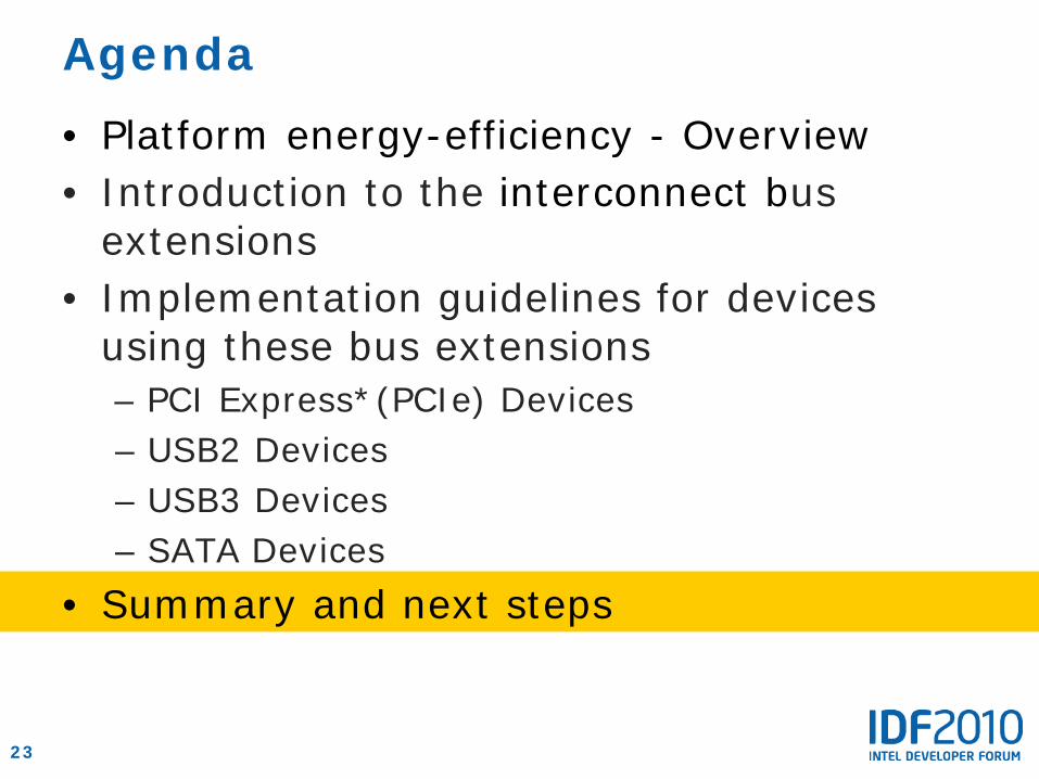
Summary and Next Steps
• Summary– Well-behaved devices optimize platform idle power§ Improves battery life for all client usage models
– Every device in the ecosystem must support the bus extensions and Intel guidelines for maximum power benefit
• Next Steps for IHVs– Start architecting devices with a view towards using the
new energy-efficient bus extensions– Work with Intel and your OEMs to understand requirements
and timeline
Early implementation provides first mover advantage and opportunity to be showcased at launch

25
Additional sources of information on this topic:• Other Sessions:
– EBLS002: Impact of “Idle” Software on Battery Life– EBLS003: Mobile Platform Idle Power Optimization –
Methodologies and Tools– PCIS002: Device guidelines for PCI Express* technology
extensions
• More web based info: – http://www.intel.com/technology/mobility/notebooks.htm§ Whitepapers under the Energy efficiency section
• Energy-efficient platform devices• Designing power friendly devices• Designing energy efficient SATA devices
− http://www.pci-sig.org− http://www.usb.org

Legal Disclaimer• INFORMATION IN THIS DOCUMENT IS PROVIDED IN CONNECTION WITH INTEL® PRODUCTS.
NO LICENSE, EXPRESS OR IMPLIED, BY ESTOPPEL OR OTHERWISE, TO ANY INTELLECTUAL PROPETY RIGHTS IS GRANTED BY THIS DOCUMENT. EXCEPT AS PROVIDED IN INTEL’S TERMS AND CONDITIONS OF SALE FOR SUCH PRODUCTS, INTEL ASSUMES NO LIABILITY WHATSOEVER, AND INTEL DISCLAIMS ANY EXPRESS OR IMPLIED WARRANTY, RELATING TO SALE AND/OR USE OF INTEL® PRODUCTS INCLUDING LIABILITY OR WARRANTIES RELATING TO FITNESS FOR A PARTICULAR PURPOSE, MERCHANTABILITY, OR INFRINGEMENT OF ANY PATENT, COPYRIGHT OR OTHER INTELLECTUAL PROPERTY RIGHT.
• Intel may make changes to specifications and product descriptions at any time, without notice.• All products, dates, and figures specified are preliminary based on current expectations, and are
subject to change without notice.• Intel, processors, chipsets, and desktop boards may contain design defects or errors known as
errata, which may cause the product to deviate from published specifications. Current characterized errata are available on request.
• Performance tests and ratings are measured using specific computer systems and/or components and reflect the approximate performance of Intel products as measured by those tests. Any difference in system hardware or software design or configuration may affect actual performance.
• Intel, Intel Sponsors of Tomorrow. and Intel Sponsors of Tomorrow. logo and the Intel logo are trademarks of Intel Corporation in the United States and other countries.
• *Other names and brands may be claimed as the property of others.• Copyright ©2010 Intel Corporation.
26

Risk Factors
27
The above statements and any others in this document that refer to plans and expectations for the second quarter, the year and the future are forward-looking statements that involve a number of risks and uncertainties. Many factors could affect Intel’s actualresults, and variances from Intel’s current expectations regarding such factors could cause actual results to differ materially from those expressed in these forward-looking statements. Intel presently considers the following to be the important factors that could cause actual results to differ materially from the corporation’s expectations. Demand could be different from Intel's expectations due to factors including changes in business and economic conditions; customer acceptance of Intel’s and competitors’ products; changes in customer order patterns including order cancellations; and changes in the level of inventory at customers. Intel operates in intensely competitive industries that are characterized by a high percentage of costs that are fixed or difficult to reduce in the short term and product demand that is highly variable and difficult to forecast. Additionally, Intel is in the process of transitioning to its next generation of products on 32nm process technology, and there could be execution issues associated with these changes, including product defects and errata along with lower than anticipated manufacturing yields. Revenue and the gross margin percentage are affected by the timing of new Intel product introductions and the demand for and market acceptance of Intel's products; actions taken by Intel's competitors, including product offerings and introductions, marketing programs and pricingpressures and Intel’s response to such actions; defects or disruptions in the supply of materials or resources; and Intel’s ability to respond quickly to technological developments and to incorporate new features into its products. The gross margin percentage could vary significantly from expectations based on changes in revenue levels; product mix and pricing; start-up costs, including costs associated with the new 32nm process technology; variations in inventory valuation, including variations related to the timing of qualifying products for sale; excess or obsolete inventory; manufacturing yields; changes in unit costs; impairments of long-lived assets, including manufacturing, assembly/test and intangible assets; the timing and execution of the manufacturing ramp and associated costs; and capacity utilization. Expenses, particularly certain marketing and compensation expenses, as well as restructuring and asset impairment charges, vary depending on the level of demand for Intel's products and the level of revenue and profits. The majority of our non-marketable equity investment portfolio balance is concentrated in the flash memory market segment, and declines in this market segment or changes in management’s plans with respect to our investment in this market segment couldresult in significant impairment charges, impacting restructuring charges as well as gains/losses on equity investments and interest and other. Intel's results could be impacted by adverse economic, social, political and physical/infrastructure conditions in countries where Intel, its customers or its suppliers operate, including military conflict and other security risks, natural disasters, infrastructure disruptions, health concerns and fluctuations in currency exchange rates. Intel’s results could be affected by the timing of closing of acquisitions and divestitures. Intel's results could be affected by adverse effects associated with product defects and errata (deviations from published specifications), and by litigation or regulatory matters involving intellectual property, stockholder, consumer, antitrust and other issues, such as the litigation and regulatory matters described in Intel's SEC reports. An unfavorable ruling could include monetary damages or an injunction prohibiting us from manufacturing or selling one or more products, precluding particular business practices, impacting our ability to design our products, or requiring other remedies such as compulsory licensing of intellectual property. A detailed discussion of these and other factors that could affect Intel’s results is included in Intel’s SEC filings, including the report on Form 10-Q for the quarter ended March 27, 2010.
Rev. 5/7/10

28
Backup Slides

29
Platform Activity Alignment
Creates PM opportunities for semi-active workloadsPlatform power savings of ~>200mW
Platforms with Activity alignment
OS tick interrupt
Device interrupts (critical)
Device traffic (deferrable)
Device traffic (critical)
Power Management Opportunity
Current Platforms
Device interrupts (deferrable)
• Not time critical
• Status Notifications
• User Command Completions
• Debug, Statistics
• Time Critical
• Buffer replenish
• Performance/ Throughput
• Buffer overflow
• Throughput/ Performance
• No Buffering constraints
• Debug dumps

30
Example: Active Ethernet NIC
500us
60us
60us 60us 60us
Low Power
Network Data
Device Buffer
Bus Transactions
Platform Components
LTR=400us
High Power
Idle
LTR
LTR=60us
Very Low Power High
Power
Timeout
LTR Threshold
Low Power
Low Power
Very Low Power
Timeout
Idle
Latency 400usec
A new LTR value is in effect no later than the value sent in the previous LTR
Latency 400usec
400us
High Power
Latency guidance based on buffer size and utilization
Low Power
LTR _Active = 60us LTR_Active_Idle = 400usec
LTR