Interactive 3D Stereoscopic Dome with Automatic Calibration€¦ · Interactive 3D Stereoscopic...
8
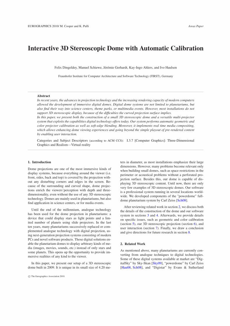
EUROGRAPHICS 2010/ M. Cooper and K. Pulli Areas Paper Interactive 3D Stereoscopic Dome with Automatic Calibration Felix Dingeldey, Manuel Schiewe, Jérémie Gerhardt, Kay-Ingo Ahlers, and Ivo Haulsen Fraunhofer Institute for Computer Architecture and Software Technology (FIRST), Germany Abstract In recent years, the advances in projection technology and the increasing rendering capacity of modern computers allowed the development of immersive digital domes. Digital dome systems are not limited to planetariums, but also find their way into science centers, theme parks, or multimedia events. However, most installations do not support 3D stereoscopic display, because of the difficulties the curved projection surface implies. In this paper, we present both the construction of a small 3D stereoscopic dome and a versatile multi-projector system that exploits the capabilities digital technology offers today. Our system performs automatic geometric and color projector calibration as well as soft-edge blending. Moreover, it implements real time media compositing, which allows enhancing dome viewing experiences and going beyond the simple playout of pre-rendered content by enabling user interaction. Categories and Subject Descriptors (according to ACM CCS): I.3.7 [Computer Graphics]: Three-Dimensional Graphics and Realism—Virtual reality 1. Introduction Dome projections are one of the most immersive kinds of display systems, because everything around the viewer (i.e. front, sides, back and top) is covered by the projection with- out any disturbing corners and edges in the screen. Be- cause of the surrounding and curved shape, dome projec- tions enrich the viewers’perception with depth and three- dimensionality, even without the use of any 3D stereoscopic technology. Domes are mainly used in planetariums, but also find application in science centers, or for media events. Until the end of the millennium, analogue technology has been used for the dome projection in planetariums: a device that could display stars as light points and a lim- ited number of planets using slide projectors. In the last ten years, many planetariums successively replaced or com- plemented analogue technology with digital projection, us- ing next-generation projection systems consisting of modern PCs and novel software products. Those digital solutions en- able the planetarium domes to display arbitrary kinds of me- dia (images, movies, sounds, etc.) instead of only stars and some planets. This opens up the opportunity to provide im- mersive realities of any kind to the viewer. In this paper, we present our setup of a 3D stereoscopic dome built in 2009. It is unique in its small size of 4.20 me- ters in diameter, as most installations emphasize their large dimensions. However, many problems become relevant only when building small domes, such as space restrictions in the perimeter or acoustical problems without a perforated pro- jection surface. Besides this, our dome is capable of dis- playing 3D stereoscopic content. Until now, there are only very few examples of 3D stereoscopic domes. Our software is a professional system running in several locations world- wide. We developed components of the "powerdome" full- dome planetarium system by Carl Zeiss [Sch08]. After reviewing related work in section 2, we discuss both the details of the construction of the dome and our software system in sections 3 and 4. Afterwards, we provide details on specific issues, such as geometric and color calibration (section 5), our 3D stereoscopic projection (section 6), and user interaction (section 7). Finally, we draw a conclusion and give directions for future research in section 8. 2. Related Work As mentioned above, many planetariums are currently con- verting from analogue techniques to digital technologies. Some of these digital systems available at market are “Dig- italSky” by Sky-Skan [Sky09], “powerdome” by Carl Zeiss [Hau08, Sch08], and “Digistar” by Evans & Sutherland c The Eurographics Association 2010.
Transcript of Interactive 3D Stereoscopic Dome with Automatic Calibration€¦ · Interactive 3D Stereoscopic...
EUROGRAPHICS 2010/ M. Cooper and K. Pulli Areas Paper
Interactive 3D Stereoscopic Dome with Automatic Calibration
Felix Dingeldey, Manuel Schiewe, Jérémie Gerhardt, Kay-Ingo Ahlers, and Ivo Haulsen
Fraunhofer Institute for Computer Architecture and Software Technology (FIRST), Germany
Abstract
In recent years, the advances in projection technology and the increasing rendering capacity of modern computers
allowed the development of immersive digital domes. Digital dome systems are not limited to planetariums, but
also find their way into science centers, theme parks, or multimedia events. However, most installations do not
support 3D stereoscopic display, because of the difficulties the curved projection surface implies.
In this paper, we present both the construction of a small 3D stereoscopic dome and a versatile multi-projector
system that exploits the capabilities digital technology offers today. Our system performs automatic geometric and
color projector calibration as well as soft-edge blending. Moreover, it implements real time media compositing,
which allows enhancing dome viewing experiences and going beyond the simple playout of pre-rendered content
by enabling user interaction.
Categories and Subject Descriptors (according to ACM CCS): I.3.7 [Computer Graphics]: Three-Dimensional
Graphics and Realism—Virtual reality
1. Introduction
Dome projections are one of the most immersive kinds of
display systems, because everything around the viewer (i.e.
front, sides, back and top) is covered by the projection with-
out any disturbing corners and edges in the screen. Be-
cause of the surrounding and curved shape, dome projec-
tions enrich the viewers’perception with depth and three-
dimensionality, even without the use of any 3D stereoscopic
technology. Domes are mainly used in planetariums, but also
find application in science centers, or for media events.
Until the end of the millennium, analogue technology
has been used for the dome projection in planetariums: a
device that could display stars as light points and a lim-
ited number of planets using slide projectors. In the last
ten years, many planetariums successively replaced or com-
plemented analogue technology with digital projection, us-
ing next-generation projection systems consisting of modern
PCs and novel software products. Those digital solutions en-
able the planetarium domes to display arbitrary kinds of me-
dia (images, movies, sounds, etc.) instead of only stars and
some planets. This opens up the opportunity to provide im-
mersive realities of any kind to the viewer.
In this paper, we present our setup of a 3D stereoscopic
dome built in 2009. It is unique in its small size of 4.20 me-
ters in diameter, as most installations emphasize their large
dimensions. However, many problems become relevant only
when building small domes, such as space restrictions in the
perimeter or acoustical problems without a perforated pro-
jection surface. Besides this, our dome is capable of dis-
playing 3D stereoscopic content. Until now, there are only
very few examples of 3D stereoscopic domes. Our software
is a professional system running in several locations world-
wide. We developed components of the "powerdome" full-
dome planetarium system by Carl Zeiss [Sch08].
After reviewing related work in section 2, we discuss both
the details of the construction of the dome and our software
system in sections 3 and 4. Afterwards, we provide details
on specific issues, such as geometric and color calibration
(section 5), our 3D stereoscopic projection (section 6), and
user interaction (section 7). Finally, we draw a conclusion
and give directions for future research in section 8.
2. Related Work
As mentioned above, many planetariums are currently con-
verting from analogue techniques to digital technologies.
Some of these digital systems available at market are “Dig-
italSky” by Sky-Skan [Sky09], “powerdome” by Carl Zeiss
[Hau08, Sch08], and “Digistar” by Evans & Sutherland
c© The Eurographics Association 2010.
F. Dingeldey, M. Schiewe, J. Gerhardt, K.-I. Ahlers, and I. Haulsen / Interactive 3D Stereoscopic Dome with Automatic Calibration
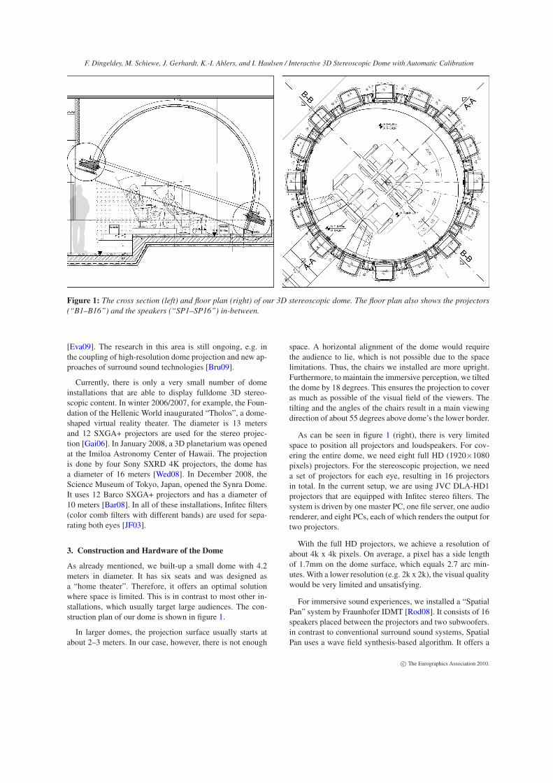
Figure 1: The cross section (left) and floor plan (right) of our 3D stereoscopic dome. The floor plan also shows the projectors
(“B1–B16”) and the speakers (“SP1–SP16”) in-between.
[Eva09]. The research in this area is still ongoing, e.g. in
the coupling of high-resolution dome projection and new ap-
proaches of surround sound technologies [Bru09].
Currently, there is only a very small number of dome
installations that are able to display fulldome 3D stereo-
scopic content. In winter 2006/2007, for example, the Foun-
dation of the Hellenic World inaugurated “Tholos”, a dome-
shaped virtual reality theater. The diameter is 13 meters
and 12 SXGA+ projectors are used for the stereo projec-
tion [Gai06]. In January 2008, a 3D planetarium was opened
at the Imiloa Astronomy Center of Hawaii. The projection
is done by four Sony SXRD 4K projectors, the dome has
a diameter of 16 meters [Wed08]. In December 2008, the
Science Museum of Tokyo, Japan, opened the Synra Dome.
It uses 12 Barco SXGA+ projectors and has a diameter of
10 meters [Bar08]. In all of these installations, Infitec filters
(color comb filters with different bands) are used for sepa-
rating both eyes [JF03].
3. Construction and Hardware of the Dome
As already mentioned, we built-up a small dome with 4.2
meters in diameter. It has six seats and was designed as
a “home theater”. Therefore, it offers an optimal solution
where space is limited. This is in contrast to most other in-
stallations, which usually target large audiences. The con-
struction plan of our dome is shown in figure 1.
In larger domes, the projection surface usually starts at
about 2–3 meters. In our case, however, there is not enough
space. A horizontal alignment of the dome would require
the audience to lie, which is not possible due to the space
limitations. Thus, the chairs we installed are more upright.
Furthermore, to maintain the immersive perception, we tilted
the dome by 18 degrees. This ensures the projection to cover
as much as possible of the visual field of the viewers. The
tilting and the angles of the chairs result in a main viewing
direction of about 55 degrees above dome’s the lower border.
As can be seen in figure 1 (right), there is very limited
space to position all projectors and loudspeakers. For cov-
ering the entire dome, we need eight full HD (1920×1080
pixels) projectors. For the stereoscopic projection, we need
a set of projectors for each eye, resulting in 16 projectors
in total. In the current setup, we are using JVC DLA-HD1
projectors that are equipped with Infitec stereo filters. The
system is driven by one master PC, one file server, one audio
renderer, and eight PCs, each of which renders the output for
two projectors.
With the full HD projectors, we achieve a resolution of
about 4k x 4k pixels. On average, a pixel has a side length
of 1.7mm on the dome surface, which equals 2.7 arc min-
utes. With a lower resolution (e.g. 2k x 2k), the visual quality
would be very limited and unsatisfying.
For immersive sound experiences, we installed a “Spatial
Pan” system by Fraunhofer IDMT [Rod08]. It consists of 16
speakers placed between the projectors and two subwoofers.
in contrast to conventional surround sound systems, Spatial
Pan uses a wave field synthesis-based algorithm. It offers a
c© The Eurographics Association 2010.

F. Dingeldey, M. Schiewe, J. Gerhardt, K.-I. Ahlers, and I. Haulsen / Interactive 3D Stereoscopic Dome with Automatic Calibration
Figure 2: Overview of major components of our software
system and their relations.
much larger sweet spot and allows positioning sound sources
very accurately in 3D space.
Because of the proximity of the audience, we cannot use a
perforated dome surface as it is often done in large domes. In
order to reduce acoustical reflections, we decided to install
a special acoustic floor and sonic absorbers at the sides that
reduce the reverberation caused by inter-reflection. Besides
this, the construction of the dome ensures sonic insulation in
order to reduce external noises coming from the projectors
or the air conditioning.
4. The Software System
Our software system consists of three major components that
seamlessly play together: The "Configurator" for planning
projection systems and computing blending and calibration
data, the "ShowManager" for authoring media shows, and
the "Player" for doing the actual play-out during a presenta-
tion. The relationship between the three components is illus-
trated in figure 2. In the following subsections, we provide
details about each component.
Figure 3: Overview of distribution of commands in the clus-
ter coming from different sources.
Figure 4: Example of a partially decoded video for one pro-
jector channel. Left: fully decoded frame; right: partially de-
coded frame.
4.1. The Player
The central component of our system is the Player. It dis-
plays shows in a rendering cluster. It is implemented in Vi-
sual C++ and uses Microsoft DirectShow for video and au-
dio processing, and Microsoft Direct3D for rendering.
The cluster is organized as a master and several slaves. In
our dome, each slave renders two channels (projector out-
puts). The master controls the whole rendering process. It
receives all commands from the ShowManager or any other
application via UDP and forwards them to the clients (see
figure 3). The resources (images, videos, audio files, etc.)
are centrally stored on a file server, from which the clients
load all required resources during initialization.
During the play-out, it is crucial to maintain synchroniza-
tion among all nodes in the cluster. Otherwise, mismatches
between projector channels in the dome would be visible.
We realize synchronization by implementing a distributed
clock shared within the cluster. For this, the clocks of the
slave computers are adjusted to match the clock of the mas-
ter. This adjustment is done via Ethernet. All messages the
master sends to the slaves are tagged with a time stamp,
which ensures the simultaneous execution of commands.
With our distributed clock method, we achieve deviations
of at most 100ns, which is enough for a frame synchroniza-
tion without genlock. However, using a genlock is indispens-
able in the case of hard-edge blending (for example, if the
Sony SXRD 4k projector is used). Otherwise, mismatches
are still visible.
Our rendering is based on media compositing that allows
to combine the different media (videos, images, text, etc.)
in real time. For the arrangement of media, we utilize layers
that define a z-ordering, as often seen in photo editing soft-
ware. For each layer, it is possible to define a modulation
color, the opacity and the blending mode. These parameters
allow to fine-tune the compositing very well. In addition, the
user can associate pixel shaders to each visual media object,
which allows to define custom rendering effects.
c© The Eurographics Association 2010.

F. Dingeldey, M. Schiewe, J. Gerhardt, K.-I. Ahlers, and I. Haulsen / Interactive 3D Stereoscopic Dome with Automatic Calibration
Figure 5: Screenshot of the ShowManager showing its main
window.
Currently, the Player is capable of playing back 4k x 4k
fulldome video content at 30 frames per second. It is not nec-
essary to slice the video material in a pre-process. Instead,
we use a specialized video codec capable of decoding only
the part of the video that is actually rendered by the current
PC. An example of this decoding is shown in figure 4.
Our system also supports the integration of external de-
vices, such as lamps, spots, fog machines, or gobos. Cur-
rently, we implemented DMX, Midi and serial interfaces. In
the show, a device is represented as regular object and can
be edited and animated like any other media object.
4.2. The ShowManager
As illustrated in figure 2, our player reads shows from XML-
files. These “shows” define the resources to be used, their
spatial and temporal placement, animations, and the com-
positing. The ShowManager as a separate application lets
users author shows very efficiently, but also allows to con-
trol the rendering cluster.
Figure 5 shows a screenshot of the main window of the
ShowManager, which is split into two halves. On top it
presents the resources of the show, a preview window, and al-
lows the user to edit parameters of objects. Below, a timeline
displays the media elements in the show. It allows the user to
place new items by simply dragging resources onto the time-
line. Additionally, existing items can be moved using drag-
drop and changed in their duration by grasping the sides with
the mouse. A “snap-to” mechanism aligns dragged objects
with other objects in the show.
An advanced animation editor allows to edit keyframe-
based animations. Different types of interpolation (linear,
spline, etc.) can be selected. A graphical editor for the ani-
mation curves facilitates the direct manipulation of keys both
in value and time.
Figure 6: Screenshot of the Configurator showing our dome
setup.
Besides allowing to author shows, the ShowManager sim-
plifies the management of the rendering cluster. It can be
started, stopped, and monitored directly from within the
ShowManager. Additionally, shows can be uploaded and
played-back, even in parallel to the authoring.
4.3. The Configurator
The Configurator is a tool for planing the physical setups
of projection systems (see figure 6). It is used to define
the shape of the screen (our system support arbitrary screen
shapes), the number and types of projectors, and their po-
sitions and orientations. It has a 3D view that visualizes all
these components including the light frustums of the projec-
tors and the screen areas covered by their projections. With
the Configurator, the user plans how the whole build-up will
look like and can check everything, even before any hard-
ware components are bought.
The soft-edge blending is calculated automatically using
the whole overlapping areas between the projectors. All im-
portant information about the installation (including pixel
sizes, the projection’s total brightness and resolution) are
generated and written into a data sheet.
The Configurator contains multiple calibration methods
for fast and easy projector fine-adjustment and color adap-
tion: manual, semi-manual and camera-based automatic ge-
ometry and color calibration (see sections 5.1 and 5.3 for
details).
The Configurator writes out the following data files that
are needed by the Player to execute the real time corrections:
blend mask images to do the soft-edge blending, distortion
meshes that define the warping for the geometric correc-
tion (including region-of-interest optimization data needed
for efficient video-decoding of movie files with a resolution
of 4k x 4k and beyond), and look-up tables for the color cal-
ibration.
c© The Eurographics Association 2010.

F. Dingeldey, M. Schiewe, J. Gerhardt, K.-I. Ahlers, and I. Haulsen / Interactive 3D Stereoscopic Dome with Automatic Calibration
5. Calibration
5.1. Geometric Calibration
The geometric calibration is done using the Configurator and
is driven by a model-based approach. The user feeds param-
eters into the system, such as the dome diameter, the number
of projectors and their positions. This input data is used to
calculate a first geometric calibration — i.e. the needed dis-
tortion of the flat and rectangular (partial) projector images
so that they are correctly adapted to the curved dome sur-
face and produce one big projection. It is not important that
these input parameters are chosen in perfect accuracy. No
matter how much effort the user puts into exact measuring
of these parameters, there will be (more or less) visible mis-
alignments in the projected images at this step of the set-up.
A flawless image will be assured later, after executing the
calibration refinement processes we describe in the follow-
ing.
The Configurator supports three kinds of geometric pro-
jector fine-adjustment: marker-based calibration, manual
calibration, and camera-based automatic calibration.
As a first step, the user can choose to execute the marker-
based calibration, starting with defining some marker posi-
tions on the screen. These are usually some points, corners
or edges at the screen itself or some LEDs, laser beams or
color markers that are only visible in UV light. The user
then moves a cursor in the projected images to the marker
positions on the screen. Using this information, the software
calculates the intrinsic (field-of view, aspect ratio, off-axis
angle, lens distortion) and extrinsic (position, orientation)
parameters of the real projectors much more precisely than
the user could measure them by hand. After this process, the
projected partial images will match significant better than
before.
Nevertheless, there still may be some visible geometric er-
rors in some areas. To eliminate these, the user can select the
manual projector calibration or the camera-based automatic
projector calibration.
During the manual projector calibration, the user moves
a cursor in the projector’s image, selects areas in this image
that seem to be misaligned and distorts them (e.g. move them
upwards, to the right, etc.). The position, size and shape of
the influenced area can be adjusted by parameters. The user
executes such manipulations on different parts of the projec-
tor’s image until all visible mismatches in the overlapping
areas have disappeared.
During the camera-based automatic projector calibration,
one or more cameras take a number of pictures while the
projectors are displaying images with special stripe patterns
generated with color-encoded structured light. The images
are filtered and analyzed which lets the software recognize
the errors in the projections because it has enough informa-
tion about where the projectors’ pixels are located on the
screen and where they should intersect the screen geometry.
The warping parameters for each projector are adapted so
that the alignment errors are reversed and, thus, eliminated.
The cameras are calibrated using the above mentioned mark-
ers once before the first automatic projector calibration is
executed.
5.2. Blending and Brightness Correction
Multi-projector systems have to deal with the edges between
the projector images when connecting the partial images of
the single projectors in order to create the resulting total im-
age. This is done using soft-edge blending. The brightness
of each image area being part of the overlapping region in-
between two projectors is reduced in a way that the result-
ing overlapping region is as bright as the rest of the global
projection to achieve a homogenous and uniform projected
image. This is done by cross-fading the light intensity in-
between the projection fields. Multi-projector systems are
usually using a linear blending function. In the Configurator,
we use sinus-based function smoothing to avoid the sharp
kinks at the start and the end of the blending areas. Finally,
the blending function must be inverse-gamma corrected be-
cause of the non-linear brightness slope of common projec-
tors.
The definition of the location and size of the blend-
ing region can be done manually, although this is a time-
consuming task if good results are to be achieved. For this
reason, the Configurator automatically calculates the opti-
mal blending regions without any further user input, simi-
lar to the approach described in [BR05]. For each point in
the overlapping region, the algorithm investigates how many
projectors are covering this point. The influence in this point
is weighted between the projectors: pixels near to a projec-
tor’s edge get a smaller weight, while pixels near to an area
where this projector is the only one that is projecting to get
a higher weight. This results in blend images that smoothly
fade out towards their edges, and in the sum the projection
brightness is uniform.
Even without the usage of any measurement devices, the
Configurator is doing a second kind of brightness correc-
tion in addition to the soft-edge blending. All pixels of each
projector are corrected with resepect to their brightness that
they have on the screen. Pixels that cover a relatively small
area on the screen (and thus look brighter than other pix-
els) are darkened by the system relative to their size so that
the whole screen gets a homogeneous brightness, even if the
projectors have strongly different distances and angles to the
screen or have different lenses and lamp powers. This cor-
rection is based only on the parameters the user has fed into
the system. That means it cannot handle projector brightness
irregularities like vignetting. This task is left to the color cal-
ibration algorithms described in the subsequent section.
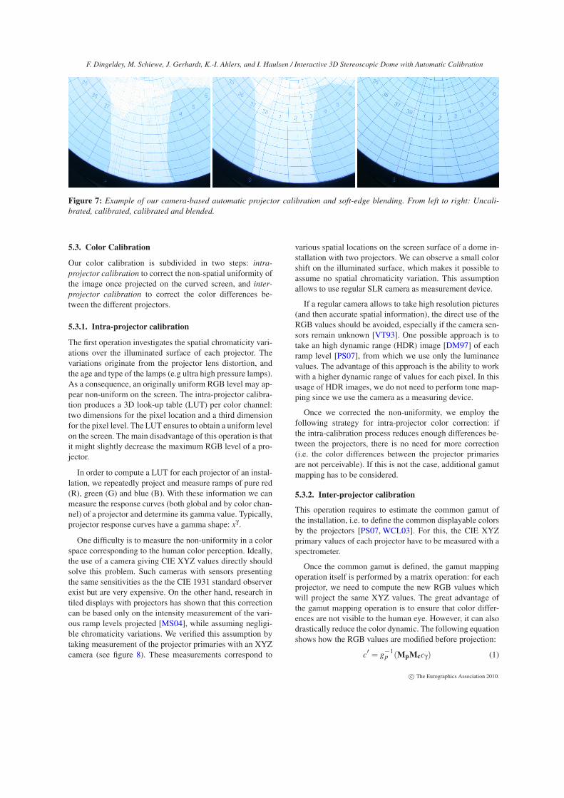
An example of our geometric calibration and blending is
shown in figure 7.
c© The Eurographics Association 2010.
F. Dingeldey, M. Schiewe, J. Gerhardt, K.-I. Ahlers, and I. Haulsen / Interactive 3D Stereoscopic Dome with Automatic Calibration
Figure 7: Example of our camera-based automatic projector calibration and soft-edge blending. From left to right: Uncali-
brated, calibrated, calibrated and blended.
5.3. Color Calibration
Our color calibration is subdivided in two steps: intra-
projector calibration to correct the non-spatial uniformity of
the image once projected on the curved screen, and inter-
projector calibration to correct the color differences be-
tween the different projectors.
5.3.1. Intra-projector calibration
The first operation investigates the spatial chromaticity vari-
ations over the illuminated surface of each projector. The
variations originate from the projector lens distortion, and
the age and type of the lamps (e.g ultra high pressure lamps).
As a consequence, an originally uniform RGB level may ap-
pear non-uniform on the screen. The intra-projector calibra-
tion produces a 3D look-up table (LUT) per color channel:
two dimensions for the pixel location and a third dimension
for the pixel level. The LUT ensures to obtain a uniform level
on the screen. The main disadvantage of this operation is that
it might slightly decrease the maximum RGB level of a pro-
jector.
In order to compute a LUT for each projector of an instal-
lation, we repeatedly project and measure ramps of pure red
(R), green (G) and blue (B). With these information we can
measure the response curves (both global and by color chan-
nel) of a projector and determine its gamma value. Typically,
projector response curves have a gamma shape: xγ.
One difficulty is to measure the non-uniformity in a color
space corresponding to the human color perception. Ideally,
the use of a camera giving CIE XYZ values directly should
solve this problem. Such cameras with sensors presenting
the same sensitivities as the the CIE 1931 standard observer
exist but are very expensive. On the other hand, research in
tiled displays with projectors has shown that this correction
can be based only on the intensity measurement of the vari-
ous ramp levels projected [MS04], while assuming negligi-
ble chromaticity variations. We verified this assumption by
taking measurement of the projector primaries with an XYZ
camera (see figure 8). These measurements correspond to
various spatial locations on the screen surface of a dome in-
stallation with two projectors. We can observe a small color
shift on the illuminated surface, which makes it possible to
assume no spatial chromaticity variation. This assumption
allows to use regular SLR camera as measurement device.
If a regular camera allows to take high resolution pictures
(and then accurate spatial information), the direct use of the
RGB values should be avoided, especially if the camera sen-
sors remain unknown [VT93]. One possible approach is to
take an high dynamic range (HDR) image [DM97] of each
ramp level [PS07], from which we use only the luminance
values. The advantage of this approach is the ability to work
with a higher dynamic range of values for each pixel. In this
usage of HDR images, we do not need to perform tone map-
ping since we use the camera as a measuring device.
Once we corrected the non-uniformity, we employ the
following strategy for intra-projector color correction: if
the intra-calibration process reduces enough differences be-
tween the projectors, there is no need for more correction
(i.e. the color differences between the projector primaries
are not perceivable). If this is not the case, additional gamut
mapping has to be considered.
5.3.2. Inter-projector calibration
This operation requires to estimate the common gamut of
the installation, i.e. to define the common displayable colors
by the projectors [PS07, WCL03]. For this, the CIE XYZ
primary values of each projector have to be measured with a
spectrometer.
Once the common gamut is defined, the gamut mapping
operation itself is performed by a matrix operation: for each
projector, we need to compute the new RGB values which
will project the same XYZ values. The great advantage of
the gamut mapping operation is to ensure that color differ-
ences are not visible to the human eye. However, it can also
drastically reduce the color dynamic. The following equation
shows how the RGB values are modified before projection:
c′ = g
−1p (MpMccγ) (1)
c© The Eurographics Association 2010.

F. Dingeldey, M. Schiewe, J. Gerhardt, K.-I. Ahlers, and I. Haulsen / Interactive 3D Stereoscopic Dome with Automatic Calibration
0 0.1 0.2 0.3 0.4 0.5 0.6 0.7 0.8 0.90
0.1
0.2
0.3
0.4
0.5
0.6
0.7
0.8
0.9
chromaticity x
ch
rom
ati
cit
y y
Chromaticities of two projectors primaries
Figure 8: Illustration of chromaticity variation between two
projectors. The measurements were taken with a camera giv-
ing directly CIE XYZ values and describe various spatial lo-
cations over the dome projection surface.
where Mp is the matrix of the projector primaries, Mc the
matrix characterizing the common gamut, cγ the correspond-
ing RGB values for the installation response curve (which is
defined by the user) and g−1p (c) the inverse response curve
function of projector p.
In an optimal case the transformation in equation 1 in-
volves the same matrix Mc for all projectors. In order to
avoid loosing a too much color dynamic, however, we can
compute a new Mc per projector by optimization. By doing
so, a tolerance of color inaccuracy can be introduced without
introducing perceivable color differences.
6. 3D Stereoscopic Dome Projection
On flat surfaces, the visualization of stereoscopic content has
been readily available for many years. Different technologies
have been developed, such as shutter glasses, or polarization
filters. However, on dome surfaces, the realization of stereo-
scopic playout is much more challenging.
In planar and cylindrical displays we can assume that the
viewers usually have a horizontal eye orientation to the pro-
jection surface and are looking straight to the screen. This
makes it easy to create one view for the left eye and one for
the right eye. In domes, it is different because particularly
close to the zenith, the orientation of the left and right eye
relative to the screen differs significantly among viewers at
different positions and angles. For example, observers stand-
ing in the dome center and looking up to the zenith have a
reversed eye orientation if they turn around 180 degrees, still
looking upwards. This means that if the observers are free to
choose their position and orientation there cannot be a reli-
able stereoscopic perception.
There are several options for stereoscopic display. First,
the polarization filter stereo technology is a relative easy and
low-price solution to execute the image separation for the
stereoscopic effect. However, on a curved screen like a dome
it is not possible to use this method because it needs a special
paint (silver screen) that keeps the polarization of the pro-
jected light that is reflected from the screen surface. The high
specular reflection characteristics of silver screens makes it
impossible to achieve a homogeneous brightness distribution
of the projection for all viewing angles. Second, the shutter
glasses stereo technology needs expensive hardware. Projec-
tors that run at least at 120 Hz and genlocked graphics cards
are required for a smooth and comfortable viewing experi-
ence. Finally, the Infitec stereo technology uses comb filters
(see also section 2) and does not have the disadvantages of
the other methods. Thus, we decided to use Infitec filters for
our 3D stereoscopic setup.
In general, the drawback of using 3D glasses is that they
usually limit the human visual field significantly, which peo-
ple may find uncomfortable. Currently, however, there are no
stereo technologies available that work without glasses and
that are suitable for large-scale curved screens.
The most challenging aspect of stereoscopic projection in
a dome is content generation for the different viewing direc-
tions. We use two different modes:
• In the "global stereo mode", the view calculations for the
two eyes are done from the static position in the dome
center. The viewing direction of both eyes is optimized for
the main direction of the dome. Hence, this method can be
best used if the audience is seated at fixed positions. The
disadvantage is that the optimal stereoscopic perception
is only given in the main direction. In other directions,
disparity and, thus, the the stereoscopic impression van-
ish. Full dome stereo movies are often created using this
method.
• In the "local stereo mode", the view calculations depend
on the displayed graphic objects. We can stereoscopically
present images, movies or 3D objects on all position in
the dome. However, this method is only feasible for ob-
jects with a size smaller than 90 degrees. Furthermore,
it does not work properly for objects in the zenith. For
these objects the rendering algorithms could be adapted
so that the eye disparity is slowly decreased as the objects
approach towards the zenith. Generally, the local stereo
mode is particularly suitable if people move around freely
in the dome and do not have a common viewing direction.
In our dome projection system, it is possible to use both
modes. In fact, the two methods can even be displayed si-
multaneously if assigned to different layers in the show.
7. User Interaction
In the past, digital dome presentations have usually been
non-interactive. The shows have been created and pre-
c© The Eurographics Association 2010.
F. Dingeldey, M. Schiewe, J. Gerhardt, K.-I. Ahlers, and I. Haulsen / Interactive 3D Stereoscopic Dome with Automatic Calibration
rendered beforehand and were simply played-back, which
does not allow any interaction with the audience. However,
to enable more exciting experiences, support for user inter-
action is highly desirable.
Our dome projection system is a real time compositing
system that renders the media on-the-fly during playout. This
allows us to introduce different interaction schemes. We can
manipulate any media in the show interactively and in real
time utilizing our animation capabilities. All parameters that
are animatable — such as opacity, position, size, etc. — can
be modified within their ranges.
Our system also allows to process live video content,
which is particularly interesting for telepresence or broad-
casting scenarios. The live video can either cover the entire
dome surface as a fulldome video. Alternatively, it is possi-
ble to map the the live stream onto a billboard and place it
at different positions in the dome. Naturally, the animation
parameters of the live video can also be manipulated inter-
actively.
We implemented two different methods for integrating
live video content. First, we can capture the video stream on
each rendering client. The advantage is a very short delay.
Second, we can setup a server that captures the video stream
and distributes it to the clients via an UDP channel. Since
the video server can usually be installed on one of the exist-
ing computers in the cluster, this method does not need any
additional hardware for distributing the stream in the cluster.
Furthermore, we can define pixel shaders per object for
advanced rendering effects. Employing a mechanism similar
to the manipulation of show objects, the parameters of the
pixel shaders can also be manipulated in real time.
8. Conclusion and Future Work
In this paper, we described the construction of our 3D stereo-
scopic dome and the software system for multi-projector
playouts. As discussed, the small size of the dome implies
several problems not present in larger installations that have
to be handled. Furthermore, we presented several special
features of our system, such as automatic geometric and
color projector calibration, automatic soft-edge blending,
real time media compositing, different stereoscopic render-
ing techniques, and user interaction.
In the future, we will increase the maximal resolution
in the dome in order to further enhance the visual quality.
Concerning the global stereoscopic rendering, we will re-
search how to improve the stereoscopic impression outside
the main viewing direction. Additionally, we want to inves-
tigate methods for directly editing and manipulate objects of
a show. For this, we plan to evaluate different intuitive user
interfaces, such as multitouch devices or gesture recognition.
As already mentioned, our live video streaming allows
to use domes for telepresence and video conferencing sys-
tems. However, this requires wide-area network streaming
with very high data rates. Another interesting application
that could benefit of our interaction capabilities is multi-user
gaming. Here, we want to develop novel schemes for group
interaction in a dome. Finally, domes could also be used for
evaluating simulation results and doing design reviews, for
example in the automobile industry.
References
[Bar08] BARCO:. http://www.barco.com/en/
Entertainment/reference/3726, 2008. as visited on2009-12-01. 2
[BR05] BIMBER O., RASKAR R.: Spatial augmented reality:Merging real and virtual worlds, 2005. 5
[Bru09] BRUHNKE J.: Unter der haube (immersive dome). Dig-
ital Production, magazine for postproduction and visualization
(November-December 2009), 27. 2
[DM97] DEBEVEC P. E., MALIK J.: Recovering high dynamicrange radiance maps from photographs. In SIGGRAPH ’97: Pro-
ceedings of the 24th annual conference on Computer graphics
and interactive techniques (New York, NY, USA, 1997), ACMPress/Addison-Wesley Publishing Co., pp. 369–378. 6
[Eva09] EVANS & SUTHERLAND:. http://www.es.com/
products/digital_theater/Digistar4/resources/pdf/
D4_Brochure_web.pdf, 2009. as visited on 2009-11-11. 2
[Gai06] GAITATZES A. E. A.: Media productions for a dome dis-play system. VRST’06: Proceedings of the ACM symposium on
Virtual reality software and technology (2006), 261. 2
[Hau08] HAULSEN I.: Projektion auf beliebige Flächen. Produc-
tion Partner (February 2008). 1
[JF03] JORKE H., FRITZ M.: Infitec — a new stereoscopic visu-alization tool by wavelength multiplexing imaging. 2
[MS04] MAJUMDER A., STEVENS R.: Color nonuniformity inprojection-based displays: analysis and solutions. Visualization
and Computer Graphics, IEEE Transactions on 10, 2 (March-April 2004), 177–188. 6
[PS07] PAGANI A., STRICKER D.: Spatially uniform colors forprojectors and tiled displays. Journal of the Society for Informa-
tion Display 15, 9 (September 2007), 679–689. 6
[Rod08] RODIGAST R.: A new method for sound production andreinforcement in planetariums. In Proceedings of the 2008 IPS
conference (2008). 2
[Sch08] SCHORCHT V.: powerdome: Three steps to projection.Innovation Special Planetariums 7 (2008), 8. 1
[Sky09] SKY-SKAN INC.:. http://www.skyskan.com/
Products/DigitalSky/cont.html, 2009. as visited on2009-11-11. 1
[VT93] VORA P. L., TRUSSELL H. J.: Measure of goodness ofa set of color-scanning filters. Journal of the Optical Society of
America. A, Optics and image science 10, 7 (September 1993),1499–1508. 6
[WCL03] WALLACE G., CHEN H., LI K.: Color gamut matchingfor tiled display walls. In EGVE ’03: Proceedings of the work-
shop on Virtual environments 2003 (New York, NY, USA, 2003),ACM, pp. 293–302. 6
[Wed08] WEDDLE M.: World’s first 3d stereo planetariumopens in hawai’i. http://www.pr.com/press-release/
67806, 2008. as visited on 2009-12-01. 2
c© The Eurographics Association 2010.