Interaction of positive streamers in air with bubbles...
14
Interaction of positive streamers in air with bubbles floating on liquid surfaces: conductive and dielectric bubbles Natalia Yu Babaeva 1,3 , George V Naidis 1 and Mark J Kushner 2 1 Joint Institute for High Temperatures, Russian Academy of Sciences, Moscow 125412, Russia 2 Department of Electrical Engineering and Computer Science, University of Michigan, 1301 Beal Ave, Ann Arbor, MI 48109-2122 United States of America E-mail: [email protected] Received 3 October 2017, revised 14 December 2017 Accepted for publication 8 January 2018 Published 25 January 2018 Abstract The interaction of plasmas sustained in humid air with liquids produces reactive species in both the gas phase and liquid for applications ranging from medicine to agriculture. In several experiments, enhanced liquid reactivity has been produced when the liquid is a foam or a bubble coated liquid. To investigate the phenomena of streamers interacting with bubbles a two- dimensional computational investigation has been performed of streamer initiation and propagation on and inside hemispherical bubble-shells floating on a liquid surface. Following prior experiments, water and oil bubble-shells with an electrode located outside and inside the bubble were investigated. We found that positive air streamers interact differently with conductive water and dielectric oil bubbles. The streamer propagates along the external surface of a water bubble while not penetrating through the bubble due to screening of the electric field by the conducting shell. If the electrode is inserted inside the bubble, the path of the streamer depends on how deeply the electrode penetrates. For shallow penetration, the streamer propagates along the inner surface of the bubble. Due to the low conductivity of oil bubble- shells, the electric field from an external electrode penetrates into the interior of the bubble. The streamer can then be re-initiated inside the bubble. Keywords: conductive and dielectric bubbles, water and oil bubble-shells, streamers interacting with bubbles 1. Introduction Plasma interacting with liquids comes in at least three vari- eties [1–3]. The first is a plasma sustained in the gas above the liquid, with or without contact of the active plasma with the liquid. Activation of the liquid largely occurs by solvation of gas phase radicals and ions through the liquid interface, though photolysis and direct charge exchange with the liquid also occur. The second method is production of a gas phase plasma inside submerged bubbles within the liquid. The liquid activation process is largely the same as the external plasma. The third is direct production of an electric discharge in the liquid. Although there are instances where these in- liquid discharges are produced in the absence of bubbles [4], the majority of discharges in liquids are likely accelerated by bubbles, pre-existing or self-generated. As such, the majority of applications of plasmas in liquids are based on plasma production inside gas bubbles [5–10]. To selectively activate the liquid, plasmas are often sustained in bubbles filled with different gases and artificially injected into liquids [11–13]. The efficiency of transfer of gas phase plasma produced reactivity into liquids by liquid-hugging plasmas or plasmas in bubbles has motivated research into several configurations of plasma-liquid systems [14–18]. Several roadmaps and reviews have recently assessed key research challenges in these areas [19–22]. From a classical perspective, foams are gas dispersions in liquids. They are comprised of a myriad of small bubbles of Plasma Sources Science and Technology Plasma Sources Sci. Technol. 27 (2018) 015016 (14pp) https://doi.org/10.1088/1361-6595/aaa5da 3 Author to whom any correspondence should be addressed. 0963-0252/18/015016+14$33.00 © 2018 IOP Publishing Ltd 1
Transcript of Interaction of positive streamers in air with bubbles...

Interaction of positive streamers in air withbubbles floating on liquid surfaces:conductive and dielectric bubbles
Natalia Yu Babaeva1,3 , George V Naidis1 and Mark J Kushner2
1 Joint Institute for High Temperatures, Russian Academy of Sciences, Moscow 125412, Russia2Department of Electrical Engineering and Computer Science, University of Michigan, 1301 Beal Ave,Ann Arbor, MI 48109-2122 United States of America
E-mail: [email protected]
Received 3 October 2017, revised 14 December 2017Accepted for publication 8 January 2018Published 25 January 2018
AbstractThe interaction of plasmas sustained in humid air with liquids produces reactive species in boththe gas phase and liquid for applications ranging from medicine to agriculture. In severalexperiments, enhanced liquid reactivity has been produced when the liquid is a foam or a bubblecoated liquid. To investigate the phenomena of streamers interacting with bubbles a two-dimensional computational investigation has been performed of streamer initiation andpropagation on and inside hemispherical bubble-shells floating on a liquid surface. Followingprior experiments, water and oil bubble-shells with an electrode located outside and inside thebubble were investigated. We found that positive air streamers interact differently withconductive water and dielectric oil bubbles. The streamer propagates along the external surfaceof a water bubble while not penetrating through the bubble due to screening of the electric fieldby the conducting shell. If the electrode is inserted inside the bubble, the path of the streamerdepends on how deeply the electrode penetrates. For shallow penetration, the streamerpropagates along the inner surface of the bubble. Due to the low conductivity of oil bubble-shells, the electric field from an external electrode penetrates into the interior of the bubble. Thestreamer can then be re-initiated inside the bubble.
Keywords: conductive and dielectric bubbles, water and oil bubble-shells, streamers interactingwith bubbles
1. Introduction
Plasma interacting with liquids comes in at least three vari-eties [1–3]. The first is a plasma sustained in the gas above theliquid, with or without contact of the active plasma with theliquid. Activation of the liquid largely occurs by solvation ofgas phase radicals and ions through the liquid interface,though photolysis and direct charge exchange with the liquidalso occur. The second method is production of a gas phaseplasma inside submerged bubbles within the liquid. Theliquid activation process is largely the same as the externalplasma. The third is direct production of an electric dischargein the liquid. Although there are instances where these in-
liquid discharges are produced in the absence of bubbles [4],the majority of discharges in liquids are likely accelerated bybubbles, pre-existing or self-generated. As such, the majorityof applications of plasmas in liquids are based on plasmaproduction inside gas bubbles [5–10]. To selectively activatethe liquid, plasmas are often sustained in bubbles filled withdifferent gases and artificially injected into liquids [11–13].The efficiency of transfer of gas phase plasma producedreactivity into liquids by liquid-hugging plasmas or plasmasin bubbles has motivated research into several configurationsof plasma-liquid systems [14–18]. Several roadmaps andreviews have recently assessed key research challenges inthese areas [19–22].
From a classical perspective, foams are gas dispersions inliquids. They are comprised of a myriad of small bubbles of
Plasma Sources Science and Technology
Plasma Sources Sci. Technol. 27 (2018) 015016 (14pp) https://doi.org/10.1088/1361-6595/aaa5da
3 Author to whom any correspondence should be addressed.
0963-0252/18/015016+14$33.00 © 2018 IOP Publishing Ltd1

mechanical or chemical origin. The bubbles are separated bythin films of a liquid [23]. Gas typically constitutes the largestvolume fraction of a foam. Plasmas interacting with foamsand bubble-covered liquids have attracted interest as means torapidly activate liquids. Activation of liquid using gas phaseplasmas is ultimately transport limited. The large surface-to-volume ratio of the liquid shells of bubbles provides a meansto accelerate activation of the liquid, in some cases havingplasma on both sides of the shell. For example, recentexperiments [24] showed that the plasma-foam system is oneof the most efficient methods for hydrogen peroxide pro-duction in a liquid phase.
In many applications, foams are not desired, and soprocesses are used to disperse or break the foam [25]. Themost commonly used methods for foam destruction arethe addition of chemical antifoam reagents which mayhave significant unwanted side effects [25], and mechanicalfoam breaking based on subjecting the foams to shear stresswith an abrupt pressure drop which results in bursting thebubble [26, 27]. Physical methods for foam control includeelectrical foam breakers based on interacting an electricdischarge with the foamy region to break up the foamleading to a decrease in the volume of the foam. Largebubbles can create numerous small bubbles when theyrupture, rather than vanishing [28]. A preliminary study onthe control of water foam by pulsed high voltage dischargesachieved favorable results using foams with thickness of10 μm [29]. This process involved passing bubbles throughthe gap between the two horizontally fixed stainless steelmesh electrodes above the water surface [30]. The air in thebubbles was released thus decreasing the growth speed ofthe foam. The bursting of the bubble was attributed to thestreamers of the discharge penetrating through the surface ofthe bubbles.
In plasma-foam systems the electric current of the dis-charge simultaneously interacts with a large number of bub-bles, often having different sizes, a condition whichcomplicates understanding the fundamental physics of theprocess. One promising approach to investigate the funda-mentals of plasma-foam interactions was introduced byAkishev et al [31] who simplified the problem to experi-mentally investigating a single streamer in air interacting witha single large bubble floating on liquid. The single-filamentstreamer discharge originated from a fixed point electrodelocated above or inside the bubble. The experiments showedthat in many cases streamers striking a bubble resulted in itsdestruction and that large bubbles (with a base diameter>5 mm) were more susceptible to streamer initiated destruc-tion than small bubbles (<2–3 mm). The experimentsaddressed both water bubble-shells floating on tap water andoil bubble-shells floating on oil. The streamers interacteddifferently with the conductive water bubble compared to thedielectric oil bubble. For example, a positive streamer inhumid air initiated outside a water bubble-shell propagatesalong the external surface of the bubble as a surface ionizationwave (SIW). A streamer striking an oil bubble gives theappearances of penetrating through the bubble into the
interior, likely a result of the streamer being reinitiated insidethe bubble.
In this paper, results from a computational investigationof streamers sustained in humid air intersecting with bubble-shells are presented, aligning with experiments performed byAkishev et al [31]. The goal of this study is to provideinsights into the mechanisms whereby streamers interact withliquid bubble-shells, as the first step towards understandinghow such plasmas interacting with foams potentially providea more efficient method to activate the liquid. All computa-tions were performed for positive streamers propagating inhumid air intersecting bubble-shells also filled with humid air.In agreement with the experiments, we found that for con-ductive bubble-shells akin to tap water, a streamer launchedfrom an electrode outside the bubble, when striking thebubble, will propagate over the outside surface of the bubbleas a SIW. If the electrode is placed inside the water bubblewith the tip near the inner surface, the streamer propagatesover the inner surface of the bubble. If the electrode tip isplaced deeply inside the bubble, the streamer will propagatedirectly towards ground. For otherwise the same conditionsbut for a non-conductive bubble-shell, the electric fieldpenetrates inside the bubble to a greater degree than the moreconductive water shell. As such, the streamer can be reini-tiated inside the bubble-shell if there is finite preionization.We also show that the charge accumulated on both sides ofthe bubbles as a result of the SIW depends on the bubbleconductivity. For a non-conductive oil bubble, these chargesmay produce forces large enough to rupture the bubble on alonger time scale.
The model, geometry and reaction mechanism are dis-cussed in section 2. Evolution of a streamer interacting with awater bubble-shell with the powered electrode outside andinside the bubble is discussed in section 3. In section 4, wediscuss the consequences of the streamer interaction and re-initiation with oil bubble-shell. Concluding remarks are insection 5.
2. Description of the model
The model used in this investigation, nonPDPSIM, is amodular, two-dimensional fluid hydrodynamics simulation.The modules in this model are sequentially executed whilesimultaneously solving Poisson’s equation for the electricpotential and transport equations for charged and neutralspecies. Poisson’s equation is solved throughout the compu-tational domain, including the gas phase, and liquid and solidmaterials. The electron temperature, Te, is obtained by solvingan electron energy conservation equation with transport andrate coefficients provided by solutions of Boltzmann’sequation. Photoionization is also included which accounts forthe production of precursor electrons ahead of the streamerfront. A detailed description of the nonPDPSIM modelingplatform can be found in [32, 33].
The gas mixture is atmospheric pressure humid airN2/O2/H2O=79.5/19.5/1 at 300 K. There are 24 speciesincluded in the model and 175 reactions between them. The
2
Plasma Sources Sci. Technol. 27 (2018) 015016 N Y Babaeva et al

species included in the model are: N2, N2(v), N2*, N2
**, N ,2+
N, N*, N+, N ,4+ O2, O2
*, O , O ,2 2+ - O−, O, O*, O+, O3,
H2O, H2O+, H2, H, OH and electrons. The reaction mech-
anism is identical to that used in [34]. Since the timescale ofinterest is that of the streamer propagation and interaction withthe bubble, less than tens of ns, cluster ions and higher orderspecies (such as nitrogen oxides) have not been included in thereaction mechanism for computational expediency as thesespecies typically form on longer timescales. We acknowledgethat for repetitive pulsing, these species may have been formedon prior pulses and so may be present during the streamerpropagation. Based on past experience, the dynamics of theionization waves are weak functions of small concentrationsof these species. Neutral transport was represented only bydiffusion (no advective motion) and gas heating was not con-sidered. By examining only the first tens of ns of streamerpropagation in stagnant ambient gas, there would not be timefor pressure gradients to initiate advective motion.
The total computational domain is shown in figure 1.This geometry is intended to represent the conditions anddimensions of the experiments performed by Akishev et al[31]. A liquid layer 3 mm thick is on the planar electrode. Thebottom surface of the computational domain under the liquidrepresenting the planar electrode is electrically grounded. Theapplied voltage is the potential boundary condition used forthe pin electrode and on the top boundary. The derivative ofthe electric potential is set to zero on the left-and-rightboundaries. Such boundary conditions provide stability to thenumerical solution, while at the same not significantlyaffecting the dynamics of the plasma in the regions of highelectric field that produce ionization.
Bubbles filled with ambient humid air are composed of awater or oil shell 35–50 μm thick on top of the liquid of thesame composition. In the water case, both the shell and theunderlying liquid are water. In the oil case, both the shell andthe underlying liquid are oil. The diameter of the base of thebubble is 15 mm. The gap between the electrode and theliquid surface is 9 mm. The distance between the pin electrode
and the top of a bubble along the central axis is 4 mm. Thedistance L between the electrode and the top of a bubble wasvaried from 1 to 10 mm. In order to investigate asymmetricgeometries with the electrode displaced from the central axis,the calculations were done in planar, Cartesian coordinates.
An unstructured numerical mesh was used having trian-gular elements with different refinement regions to resolve thebubble-shell, bubble interior and the region near the highvoltage electrode. The mesh consists of approximately 15 200nodes, of which more than 9500 are in the plasma region toresolve the plasma filaments. The mesh spacing spanned from4 μm in the path of the streamer (both in the gas phase andalong the surface) to as large as 500 μm in the periphery ofthe mesh. The electrical potential is specified on the groundplane beneath the liquid and on the powered electrode. Onnon-metal points on the right and left boundaries of thecomputational mesh, von Neumann conditions are imposed,where the gradient of the electric potential, the electric field,is zero.
The water shell and water layer are treated as lossydielectrics, and have relative permittivity ε/ε0=80 andconductivity σ=7.5×10⁻⁴Ω−1 cm−1, akin to tap water.The oil shell and oil layer have a relative permittivity ofε/ε0=2 and a conductivity σ=1.5×10⁻⁷Ω−1 cm−1.These values of conductivity are chosen to represent theexperimental conditions [31]. The applied voltage (25 kV) ishigher than in the experiment (15.2 kV) because we use asmooth rounded electrode to avoid numerical instability (nearthe powered electrode) as opposed to a sharpened tip elec-trode as used in experiment [31]. The voltage rise time is0.1 ns, intended to represent a step-function in voltage. Inmost cases, to initiate the discharge, a small cloud of elec-trically neutral seed-charges (electrons and N2
+) with a radiusof 100 μm and a peak density of 1×108 cm−3 was placednear the tip of the powered electrode. The same cloud of seed-charges was placed inside the bubbles on the bubble axis tostudy the possible re-initiation of a streamer beneath thebubble-shell. To assess the sensitivity of predictions of themodel to the position of the initial small cloud of plasma,clouds were placed at different locations shown by the reddots in figure 1. The initial plasma density was also uniformlyset to 5×103 cm−3 inside the bubble. In general, theresulting behavior of the discharge was qualitatively the sameto the base case except for a change in the time for devel-opment of the discharge. This latter observation is a result ofthe well-known formative lag time in breakdown where dis-charges take longer to develop as the initial electron densitydecreases [35].
The authors acknowledge that this problem is intrinsi-cally three-dimensional in nature whereas the computationaltool is two-dimensional. When the pin electrode is alignedwith the central axis, a 2D simulation using cylindricalcoordinates would be more rigorous. However, using Carte-sian coordinates in 2D for all cases enables side-by-sidecomparisons of cases that may not have this symmetry, forexample, when the pin-electrode is displaced from the axis.One direct consequence of using the 2D Cartesian coordinatesystem is that geometrical electric field enhancement (e.g. at
Figure 1. The total computational domain representing the experi-ments of Akishev et al [31]. Bubbles in humid air and filled withambient air composed of water or oil 35–50 μm thick float on a3 mm layer of water or oil. The diameter of the bubble base is15 mm. The gap between the electrode and the liquid surface is9 mm, applied voltage is 25 kV. The pin electrode is displaced adistance L (1–10 mm) from the axis. The red dots show the differentlocations of the initial seed charges that were investigated.
3
Plasma Sources Sci. Technol. 27 (2018) 015016 N Y Babaeva et al

Figure 2. Time evolution of (a) plasma potential and electric field, and (b) electron density and positive space charge for a streamerinteracting with a water bubble-shell with L=1 mm. Potential lines are drawn every 2 kV. There is an enhancement of the electric field atthe water shell-air boundary. The streamer approaches the surface of the bubble and spreads over it but does not penetrate into the bubble.The maximum value or range of values is shown for each frame.
4
Plasma Sources Sci. Technol. 27 (2018) 015016 N Y Babaeva et al

the tip of the electrode) is smaller than when fully resolved in3D. It is for this reason that we use a higher value of potentialthan in the experiment.
3. Streamer interaction with a water bubble-shell
As the base case, we consider a positive streamer interactingwith a water bubble-shell with the powered electrode having a1 mm offset from the axis of the bubble (L=1 mm). Thetime evolution of the electric potential and electric field as thestreamer propagates from the pin electrode towards ground isshown in figure 2(a). (The potential lines are drawn every2 kV.) The electron density and positive space charge areshown in figure 2(b), and the electron impact ionizationsource and electron temperature are shown in figure 3. Thecombined conductivity and dielectric constant of tap-waterproduces a capacitive material with resistive losses—that is, alossy dielectric. The water has a dielectric relaxation time ofτ=ε/σ=9.4 ns. The streamer propagates across the gapbetween the electrode and the surface of the bubble in about10–13 ns, and its interaction with the bubble extends to about27 ns. The shell of the bubble will both support some amountof charging while also shielding some of the applied potential
from the interior of the bubble due to the dielectric relaxationtime being commensurate with the total interaction time.
The electron density is 3×1013 cm−3 in the volume ofthe streamer, increasing to 1014 cm−3 when streamer touchesthe water shell. The trajectory of the streamer is not strictlyvertical. As the streamer approaches the bubble it reorients tobeing nearly parallel to the surface normal of the bubble inrecognition of the conductive properties of the bubble. (Theelectric field at the surface of a conductor is normal to thesurface.) As the streamer approaches the bubble, the potentiallines do penetrate through the shell and into the bubble, aconsequence of the dielectric properties and thin dimension ofthe shell. This penetration of the electric field into the shellenables enhancement in the electric field at the surface of thebubble resulting from the refraction of potential lines at thebubble-shell boundary.
After striking the bubble, the volume streamer transformsinto a surface streamer or SIW which then propagates over thebubble surface towards ground in both directions. There isalmost no visible motion of the streamer from 14 to 20 ns,which results from the charging of the high capacitance of thewater bubble-shell. (The local capacitance is ≈0.15 pF cm−2.)The dielectric properties of the shell enable there to bepositive charging to 3×1013 cm−3 at the surface whichproduces parallel components of the electric field which
Figure 3. Time evolution of the electron impact ionization source and electron temperature for a water bubble-shell with L=1 mm. There isnon-zero electron temperature inside the bubble due to the present of a small amount of electrons. The insets show enlargements of thesurface ionization wave. The maximum value or range of values is shown for each frame.
5
Plasma Sources Sci. Technol. 27 (2018) 015016 N Y Babaeva et al
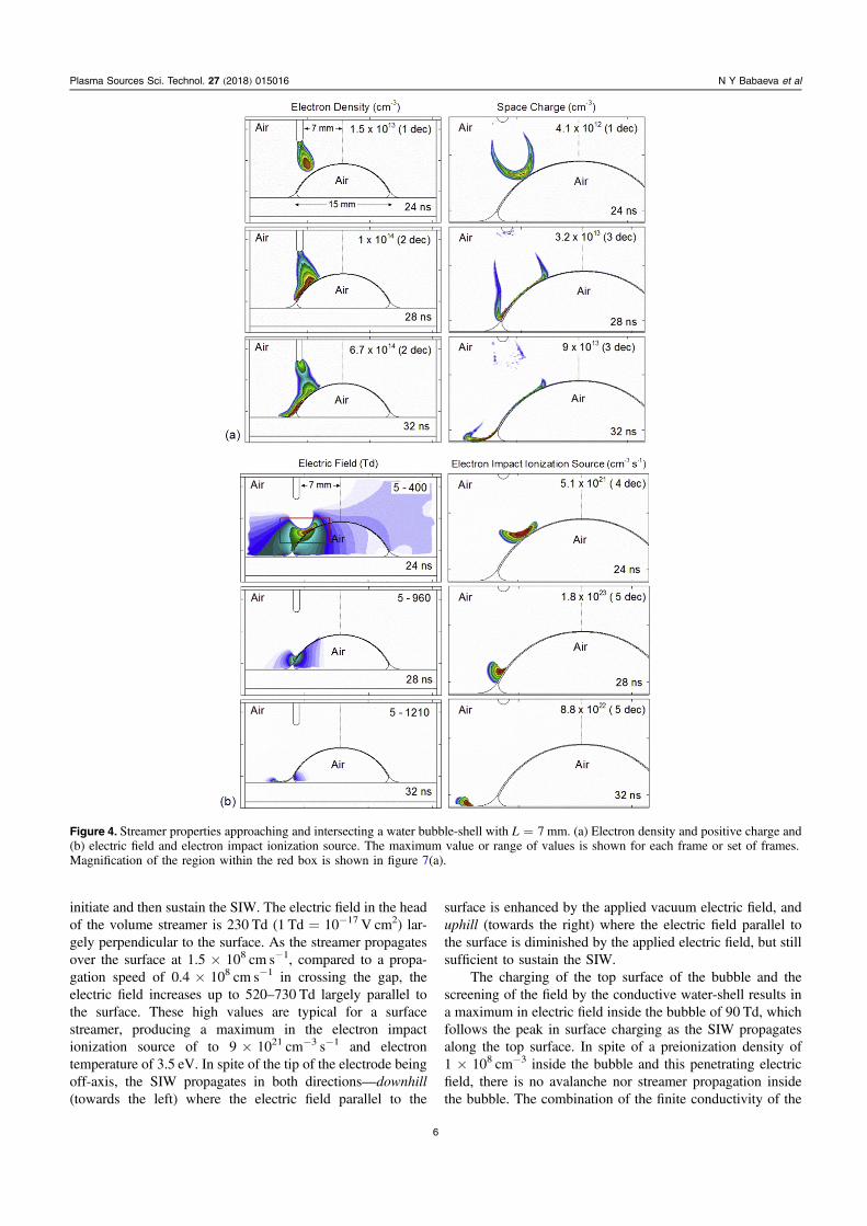
initiate and then sustain the SIW. The electric field in the headof the volume streamer is 230 Td (1 Td=10−17 V cm2) lar-gely perpendicular to the surface. As the streamer propagatesover the surface at 1.5×108 cm s−1, compared to a propa-gation speed of 0.4×108 cm s−1 in crossing the gap, theelectric field increases up to 520–730 Td largely parallel tothe surface. These high values are typical for a surfacestreamer, producing a maximum in the electron impactionization source of to 9×1021 cm−3 s−1 and electrontemperature of 3.5 eV. In spite of the tip of the electrode beingoff-axis, the SIW propagates in both directions—downhill(towards the left) where the electric field parallel to the
surface is enhanced by the applied vacuum electric field, anduphill (towards the right) where the electric field parallel tothe surface is diminished by the applied electric field, but stillsufficient to sustain the SIW.
The charging of the top surface of the bubble and thescreening of the field by the conductive water-shell results ina maximum in electric field inside the bubble of 90 Td, whichfollows the peak in surface charging as the SIW propagatesalong the top surface. In spite of a preionization density of1×108 cm−3 inside the bubble and this penetrating electricfield, there is no avalanche nor streamer propagation insidethe bubble. The combination of the finite conductivity of the
Figure 4. Streamer properties approaching and intersecting a water bubble-shell with L=7 mm. (a) Electron density and positive charge and(b) electric field and electron impact ionization source. The maximum value or range of values is shown for each frame or set of frames.Magnification of the region within the red box is shown in figure 7(a).
6
Plasma Sources Sci. Technol. 27 (2018) 015016 N Y Babaeva et al

water shell and the charging of the surface, produce sufficientshielding to prevent avalanche inside the bubble.
Exhaustive studies have not been performed on the sizeof the computational domain and the location of boundarieson the streamer properties. However, we have confirmed thatthe width of the domain used in this investigation does notsignificantly affect the value of the electric field where ava-lanches occur—beginning at the tip of the electrode and at thehead of the volume and SIW (see, for example, figure 2(a)).
Streamer properties (electron density, space charge,electric field and electron impact ionization source) with the
point electrode offset from the axis are shown in figure 4 forL=7 and figure 5 for L=10 mm. The general trends aresimilar as those for L=1 mm. However, since the effectivegas-gap length is larger as L increases, the effective electricfield is smaller for L=7 and 10 mm compared to L=1 mm.The progressively increasing curvature of the surface underthe electrode tip as L increases then increasingly aligns theapplied electric field with being parallel to the surface. As Lincreases, the vacuum electric fields begin to resemble thoseof the traditional point-to-plane geometry, with the electricfield progressively directed towards the ground plane.
Figure 5. Streamer properties approaching and intersecting a water bubble-shell with L=10 mm. (a) Electron density and positive charge;and (b) electric field and electron impact ionization source. The maximum value or range of values is shown for each frame or set of frames.Magnification of the region within the red box is shown in figure 7(b).
7
Plasma Sources Sci. Technol. 27 (2018) 015016 N Y Babaeva et al

However, with there being a finite conductivity of the shell,there is some tendency for the electric field to reorient tobeing perpendicular to the surface of the shell close to thesurface. The lower vacuum electric field with increasing Lproduces slower avalanche speeds (0.4×108 cm s−1 forL=7 mm and 0.25×108 cm s−1 for L=10 mm), andlonger delays for the streamer to strike the bubble (25 ns forL=7 mm and 40 ns for L=10 mm).
As in the L=1 mm case, after the volume streamertouches the shell, a SIW is launched. Due to the progressivelylarger component of the applied electric field pointing
downward parallel to the surface, the SIW propagates onlydownhill for both L=7 and 10 mm. The electron density andelectron impact ionization source are shown in figure 6 for aselection of electrode offset values, L=1–7 mm. The trans-ition point at which propagation of the SIW is only downhillis L=6–7 mm. For the smaller offset, the SIW propagatesboth uphill and downhill with gradually decreasing right(uphill) wing with increasing L.
The SIW extends the conductive plasma channel towardsthe edge of the bubble and, finally, to the grounded waterlayer. When the SIW reaches the flat water layer, a restrike
Figure 6. Electron density and electron impact ionization source for electrode offset L=1, 2, 3, 4, 5 and 7 mm. The insets showenlargements of the surface ionization wave. The maximum value or range of values is shown for each frame.
8
Plasma Sources Sci. Technol. 27 (2018) 015016 N Y Babaeva et al

occurs back towards the powered electrode. The restrike takesthe form of a negative ionization wave that propagatesupwards through the surface hugging plasma on the shell, andthrough the plasma channel in the gas (see the last row offrames in figures 5(a) and (b)). The restrike occurs in part dueto attachment and recombination in the plasma column duringthe 45 ns required for the SIW to reach the water layer. Thisreduction in electron density reduces the conductivity of theplasma column and enables a critically large electric field tobe sustained to launch the restrike. Note that restrikes occur inmost cases where the gap is large enough for attachment tooccur and the electron density in the channel decays, aphenomenon that is also observed in plasma jets [36, 37].
Upon intersection of a streamer with the bubble-shell, aconductive streamer channel extends from the poweredelectrode to the surface of the shell, translating the appliedpotential to the bubble. Since the conductivity of the watershell is finite, there is only moderate electric field penetrationthrough the shell to the interior of the bubble, as shown infigure 7. For example, for the offset L=7 mm the electricfield at the tip of the streamer exceeds 440 Td while thatinside the bubble is not larger than 190 Td. For an offset ofL=10 mm the electric field outside the bubble is ≈400 Tdwhereas inside the bubble, the electric field is not larger than160 Td. We found that the most sensitive parameter indetermining the electric field inside the bubble was the
Figure 7. Electric field in vicinity of the streamer tip approaching thebubble surface for electrode offsets of (a) L=7 mm and (b) L=10 mm. Electric field enhancement occurs near the shell. At the sametime, there is screening of the electric field from the interior of theshell by the conductive water-shell.
Figure 8. Plasma properties when the powered electrode tip is placedinside the water bubble-shell. (left) Electron density and (right)electron impact ionization source. (a) Electrode tip 5 mm above thewater surface, V=15 kV. The streamer propagates along theinterior surface of the bubble, until reaching the water surface, atwhich time it propagates inwards. (b) Tip is 3 mm above the water,V=15 kV. (c) Tip is 3.8 mm above the water surface, V=25 kV.Both surface and volume streamers occur. The maximum value orrange of values is shown for each frame.
9
Plasma Sources Sci. Technol. 27 (2018) 015016 N Y Babaeva et al
conductivity of the shell and (to a lesser extent) the dielectricconstant of the shell.
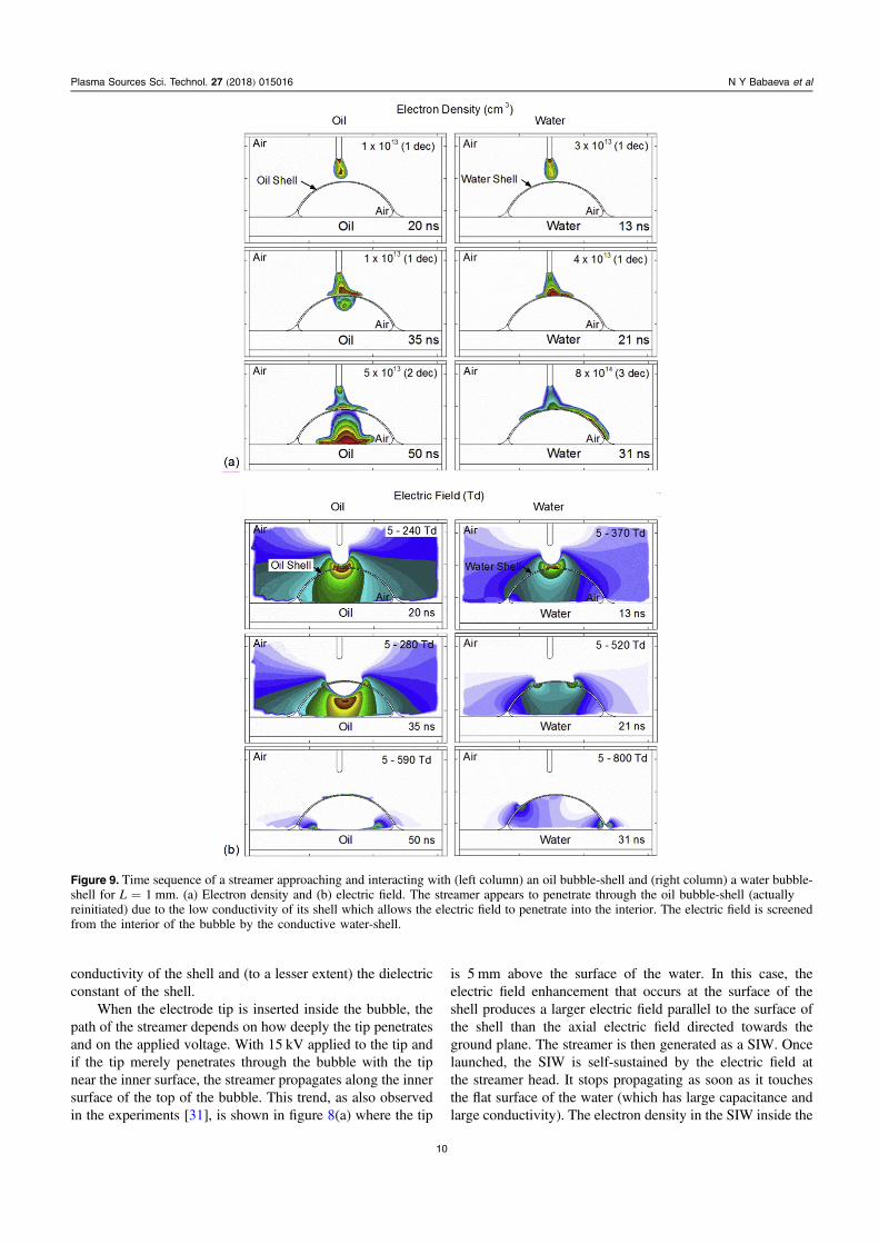
When the electrode tip is inserted inside the bubble, thepath of the streamer depends on how deeply the tip penetratesand on the applied voltage. With 15 kV applied to the tip andif the tip merely penetrates through the bubble with the tipnear the inner surface, the streamer propagates along the innersurface of the top of the bubble. This trend, as also observedin the experiments [31], is shown in figure 8(a) where the tip
is 5 mm above the surface of the water. In this case, theelectric field enhancement that occurs at the surface of theshell produces a larger electric field parallel to the surface ofthe shell than the axial electric field directed towards theground plane. The streamer is then generated as a SIW. Oncelaunched, the SIW is self-sustained by the electric field atthe streamer head. It stops propagating as soon as it touchesthe flat surface of the water (which has large capacitance andlarge conductivity). The electron density in the SIW inside the
Figure 9. Time sequence of a streamer approaching and interacting with (left column) an oil bubble-shell and (right column) a water bubble-shell for L=1 mm. (a) Electron density and (b) electric field. The streamer appears to penetrate through the oil bubble-shell (actuallyreinitiated) due to the low conductivity of its shell which allows the electric field to penetrate into the interior. The electric field is screenedfrom the interior of the bubble by the conductive water-shell.
10
Plasma Sources Sci. Technol. 27 (2018) 015016 N Y Babaeva et al

bubble is 3×1015 cm−3, which is one-two decades largerthan that for the SIW outside the bubble.
If the tip of the electrode penetrates deeply into thebubble two streamers can occur—a SIW and a weak volumestreamer. These trends are shown in figure 8(b) for an appliedpotential of 15 kV and for the tip 3 mm above the surface ofthe water. The volume streamer decays before reaching thesurface of the water, in part due to shielding of electric fieldby the evolving SIWs. With higher applied voltage (25 kV),the SIW and volume streamers can simultaneously propagate,shown in figure 8(c) for a tip height of 3.8 mm. The SIWsdecay when they reach the flat water surface. Followingtouching the flat liquid, the volume streamer propagates as acounter-propagating SIW a short distance over the surfacebefore decaying.
4. Streamer interaction with an oil bubble-shell
The behavior of positive streamers interacting with waterbubble-shells is dominated in large part by the inability of thestreamer to penetrate into the interior of the bubble due to thefinite conductivity of the shell. Streamers behave quite dif-ferently when approaching a bubble-shell composed of non-conducting oil having a lower dielectric constant. With boththe shell and underlying liquid being oil, the vacuum Lapla-cian electric field differs from that of the water shell. Com-parisons of the electron density and electric field for streamersapproaching oil and water bubble-shells are in figure 9 forL=1 mm. Due to the lower conductivity and lower dielectricconstant of the oil shell, the electric field lines experiencelittle refraction and little electric field enhancement at the
Figure 10. Plasma properties as a function of time for an oil-shell bubble with the electrode offset by L=5 mm. (left) Electron density and(right) electron impact ionization source. The insets show enlargements of the surface ionization wave. The maximum value or range ofvalues is shown for each frame.
11
Plasma Sources Sci. Technol. 27 (2018) 015016 N Y Babaeva et al

surface of the shell. The approaching streamer rapidly chargesthe capacitance of the shell, producing an electric field ofcomparable magnitude inside the bubble as on the top of thebubble. With preionization in the bubble, this electric field issufficient to reinitiate the streamer inside the bubble. With therelative absence of electric field enhancement at the insidesurface of the bubble, a SIW is not launched, and the streamerpropagates downward towards the ground plane.
This ability of streamers to be relaunched on the oppositeside of dielectric layers has been previously investigated bysimulations [38, 39] and experiments [40–42]. They foundthat re-ignition is ultimately due to penetration of electric fieldthrough the dielectric, with the re-ignition being sensitive tothe dielectric constant, thickness, transparency (for ionizingradiation) and placement of the dielectric.
The re-initiation of a streamer inside an oil-shell bubbleproceeds in a more complicated manner when the electrodetip is shifted from the bubble axis. As shown in figure 10 withL=5 mm, following the initial volume streamer striking theshell, two SIWs are simultaneously initiated which propagateover the inner and outer surfaces of the shell. The componentof the applied electric field parallel to the surface, both aboveand below the low conductivity shell, is large enough tosupport propagation of both SIW. After reaching the watersurface, the SIW on the outer surface decays, while the SIWon the inner surface reverses direction and propagates across
the surface of the liquid. There is sufficient surface charging(both inside and outside the bubble) that generates horizontalcomponents of the electric field that the SIW can propagatealong the surface of the water in the opposite direction fromthe vacuum field. As the SIW on the liquid passes under thetip, the propagation speed increases as now the vacuumelectric field points in the direction of propagation. At aboutthe time that the SIW reaches the bottom of the shell, a weakvolume streamer inside the bubble is launched from thelocation at which the initial streamer strikes the outside of thebubble. This volume streamer crosses the shell and intersectsthe SIW on the liquid. The launching of this volume streameris aided by vertical electric field components produced bycharging of the bubble at the site of the initial streamerstriking the bubble.
Due to the higher conductivity of water, the charge thataccumulates on the outer and inner surfaces of the shell isdissipated during the finite dielectric relaxation time. Atapproximately the same time during the evolution of thedischarge, the positive surface charge on the oil shell with adielectric relaxation time of 1.2×10⁻⁶ s (1.3×1013 cm−3)is nearly three times larger than that on the water shell(5×1012 cm−3), as shown in figure 11. The re-initiation ofthe streamer inside the bubble produces charge on the interiorsurface of the shell as well [38, 39] showing positive chargeaccumulated on the outer shell and negative charges on theinner shell of the water and oil bubbles. The negative chargeson the inner surface on the oil shell (1.1×1013 cm−3) arenearly one order of magnitude larger in density than those onthe water shell (1.3×1010 cm−3).
5. Concluding remarks
The interaction of atmospheric pressure plasmas with foamshas proven to be promising for producing high levels ofactivation in the liquid. Results from a two-dimensionalcomputational investigation of a single streamer in air inter-secting an isolated water or oil bubble-shell filled with humidair and floating on a liquid surface have produced insights tothese processes. The conditions resemble those of recentexperiments [31]. We found that, as in the experiments, astreamer striking a water bubble-shell pauses to charge thecapacitance of the shell, and then propagates along the outsidethe shell as a SIW. The SIW will propagate both uphill(against the applied electric field) and downhill (with theapplied electric field) depending on the location of the pow-ered electrode. The conductivity of the tap-water shell is highenough to partly shield the applied field from the interior.Two consequences are that the incident streamer will alignwith the normal to the outer surface of the shell, and theelectric field that penetrates into the bubble is too weak toreinitiate the streamer. Due to the low conductivity of the oilbubble-shell, the electric field significantly penetrates into theinterior of the bubble. The streamer can then be re-initiatedinside the bubble beneath the streamer. Note that the characterof streamer interaction with a deionized (distilled) waterbubble-shell, with a liquid conductivity one-two orders lower
Figure 11. Comparison of the positive and negative space chargesaccumulated on oil and water bubble-shell. The amount of charge onthe surface of the water bubble is three times lower than for the oilbubble.
12
Plasma Sources Sci. Technol. 27 (2018) 015016 N Y Babaeva et al

than that of tap water, can be expected to be similar to that ofan oil bubble-shell.
Although the results discussed here are in qualitativeagreement with experiments [31], the experiments wereconducted on longer time scales (μs and ms) than the simu-lations. One phenomenon that is not captured in the simula-tions is perforation of the oil bubble-shell. This perforationtakes place on millisecond time scales, and may be due to themechanical stresses applied to the shell by differential char-ging on the top and bottom of the shell [28]. Analogous to theexperiment, we also observed a streamer penetration into theoil bubble-shell. However, in the model, the penetrationresults from re-initiation of the streamer under the bubble-shell whereas in the experiment there is evidence that per-foration of the shell enables the streamer to continue into theinterior.
Acknowledgments
The work of NB and GN was supported by the RussianScience Foundation (Grant 14-12-01295-П). The work ofMJK was supported by US Department of Energy Office ofFusion Energy Science (DE-SC000319 and DE-SC0014132),and the US National Science Foundation (PHY-1519117).The authors are grateful to Professor Yu Akishev for helpfuldiscussions.
ORCID iDs
Natalia Yu Babaeva https://orcid.org/0000-0002-3762-8542George V Naidis https://orcid.org/0000-0003-2184-802XMark J Kushner https://orcid.org/0000-0001-7437-8573
References
[1] Kolb J F, Joshi R P, Xiao S and Schoenbach K H 2008Streamers in water and other dielectric liquids J. Phys. D:Appl. Phys. 41 234007
[2] Levko D, Sharma A and Raja L L 2016 Microwave plasmasgenerated in bubbles immersed in liquids for hydrocarbonsreforming J. Phys. D: Appl. Phys. 49 22LT01
[3] Levko D, Sharma A and Raja L L 2017 Non-thermal plasmaethanol reforming in bubbles immersed in liquids J. Phys. D:Appl. Phys. 50 085202
[4] Starikovskiy A, Yang Y, Cho Y I and Fridman A 2011Nonequilibrium plasma in liquid water: dynamics ofgeneration and quenching Plasma Sources Sci. Technol. 20024003
[5] Aoki H, Kitano K and Hamaguchi S 2008 Plasma generationinside externally supplied Ar bubbles in water PlasmaSources Sci. Technol. 17 025006
[6] Gershman S, Mozgina O, Belkind A, Becker K andKunhardt E 2007 Pulsed electrical discharge in bubbledwater Contrib. Plasma Phys. 47 19
[7] Bruggeman P, Leys C and Vierendeels J 2007 Experimentalinvestigation of dc electrical breakdown of long vapourbubbles in capillaries J. Phys. D: Appl. Phys. 40 1937
[8] Foster J E, Weatherford B R, Gillman E and Yee B 2010Underwater operation of a DBD plasma jet Plasma SourcesSci. Technol. 19 25001
[9] Vanraes P, Nikiforov A and Leys C 2012 Electrical andspectroscopic characterization of underwater plasmadischarge inside rising gas bubbles J. Phys. D: Appl. Phys.45 245206
[10] Hamdan A and Cha M S 2015 Ignition modes of nanoseconddischarge with bubbles in distilled water J. Phys. D: Appl.Phys. 48 405206
[11] Tachibana K, Takekata Y, Mizumoto Y, Motomura H andJinno M 2011 Analysis of a pulsed discharge within singlebubbles in water under synchronized conditions PlasmaSources Sci. Technol. 20 034005
[12] Sommers B S, Foster J E, Babaeva N Y and Kushner M J 2011Observations of electric discharge streamer propagation andcapillary oscillations on the surface of air bubbles in waterJ. Phys. D: Appl. Phys. 44 082001
[13] Akishev Y S, Grushin M E, Karalnik V B, Petryakov A V andTrushkin N I 2012 Atmospheric pressure pulsed-periodicalspark generator forming fast moving non-equilibriumplasma clouds IEEE Trans. Plasma Sci. 40 2806–11
[14] Schmidt-Bleker A, Winter J, Iseni S, Dunnbier M,Weltmann K and Reuter S 2014 Reactive species output of aplasma jet with a shielding gas device—combination ofFTIR absorption spectroscopy and gas phase modellingJ. Phys. D: Appl. Phys. 47 145201
[15] Van Gans W and Bogaerts A 2014 Reaction pathways ofbiomedically active species in an Ar plasma jet PlasmaSources Sci. Technol. 23 035015
[16] Naidis G V 2014 Production of active species in cold helium–
air plasma jets Plasma Sources Sci. Technol. 23 065014[17] Graves D B 2012 The emerging role of reactive oxygen and
nitrogen species in redox biology and some implications forplasma applications to medicine and biology J. Phys. D:Appl. Phys. 45 263001
[18] Kanazawa S, Kawano H, Watanabe S, Furuki T, Akamine S,Ichiki R, Ohkubo T, Kocik M and Mizeraczyk J 2011Observation of OH radicals produced by pulsed dischargeson the surface of a liquid Plasma Sources Sci. Technol. 20034010
[19] Bruggeman P and Leys C 2009 Non-thermal plasmas in and incontact with liquids J. Phys. D: Appl. Phys. 42 053001
[20] Bruggeman P J et al 2016 Plasma–liquid interactions: a reviewand roadmap Plasma Sources Sci. Technol. 25 053002
[21] Adamovich I et al 2017 The 2017 plasma roadmap: lowtemperature plasma science and technology J. Phys. D:Appl. Phys. 50 323001
[22] Foster J E 2017 Plasma-based water purification: challengesand prospects for the future Phys. Plasmas 24 055501
[23] Vardar-Sukan F 1998 Foaming: consequences, prevention anddestruction Biotechnol. Adv. 16 913–48
[24] Rafati A M and Ashrafizadeh S N 2010 The importance offoams and antifoaming in bioprocesses Pak. J. Biotechnol. 719–39
[25] Schugerl K 2000 Recovery of proteins and microorganismsfrom cultivation media by foam flotation Advances inBiochemical Engineering/Biotechnology ed T Scheper vol68 (Berlin: Springer)
[26] Carr E L, Eales K, Soddell J and Seviour R J 2005 Improvedpermeabilization protocols for fluorescence in situhybridization (FISH) of mycolic-acid containing bacteriafound in foams J. Microbiol. Methods 61 47–54
[27] Chisti Y 1993 Animal cell culture in stirred bioreactors:observations on scale-up Process Biochem. 28 511–7
13
Plasma Sources Sci. Technol. 27 (2018) 015016 N Y Babaeva et al

[28] Bird J C, de Ruiter R, Courbin L and Stone H A 2010 Daughterbubble cascades produced by folding of ruptured thin filmsNature 465 759
[29] Izmailov M M, Kazenin D A, Kutepov A M and Tsablinova I A1990 Methods and equipment for foam damping usingelectric and magnetic effects Chem. Petrol. Eng. 26 463
[30] Shidong Y, Fengguo C and Jun M 2008 Preliminary study oncontrol of water treatment foam by pulsed high voltagedischarge 2nd Int. Conf. on Bioinformatics and BiomedicalEngineering, ICBBE
[31] Akishev Y, Arefi-Khonsari F, Demir A, Grushin M,Karalnik V, Petryakov A and Trushkin N 2015 Theinteraction of positive streamers with bubbles floating on aliquid surface Plasma Sources Sci. Technol. 24 065021
[32] Norberg S A, Johnsen E and Kushner M J 2015 Formation ofreactive oxygen and nitrogen species by repetitive negativelypulsed helium atmospheric pressure plasma jets propagatinginto humid air Plasma Sources Sci. Technol. 24 035026
[33] Babaeva N Y, Tereshonok D V and Naidis G V 2016 Fluid andhybrid modelling of nanosecond surface discharges: effectof polarity and secondary electrons emission PlasmaSources Sci. Technol. 25 044008
[34] Babaeva N Y and Kushner M J 2013 Reactive fluxes deliveredby dielectric barrier discharge filaments to slightly woundedskin J. Phys. D: Appl. Phys. 46 025401
[35] Loeb L B 1959 Significance of formative time lags in gaseousbreakdown Phys. Rev. 113 7
[36] Sigmond R S 1984 The residual streamer channel: return strokeand secondary streamer J. Appl. Phys. 56 1355
[37] Darny T, Pouvesle J-M, Peuch V, Douat C, Dozias S andRobert E 2017 Analysis of conductive target influence inplasma jet experiments through helium metastable andelectric field measurements Plasma Source Sci. Technol. 26045008
[38] Pechereau F, Jansky J and Bourdon A 2012 Simulation of thereignition of a discharge behind a dielectric layer in air atatmospheric pressure Plasma Sources Sci. Technol. 21055011
[39] Pechereau F and Bourdon A 2014 Influence of the polarity ofthe applied voltage on the reignition of a discharge below adielectric layer in air at atmospheric pressure J. Phys. D:Appl. Phys. 47 445206
[40] Algwari Q T and O’Connell D 2011 Plasma jet interactionwith a dielectric surface IEEE Trans. Plasma Sci. 392368–9
[41] Lu X et al 2009 Propagation of an atmospheric pressure plasmaplume J. Appl. Phys. 105 043304
[42] Wu S, Wang Z, Huang Q, Xiong Q and Lu X 2011 Plasmaplume ignited by plasma plume at atmospheric pressureIEEE Trans. Plasma Sci. 39 2292–3
14
Plasma Sources Sci. Technol. 27 (2018) 015016 N Y Babaeva et al