Interaction of Photons with matter -...
23
Interaction of Photons with matter K. K. Abdullah “Studies on X-ray interactions near K-edge using 241 Am source and Proton Induced X-ray Emission (PIXE) ” Thesis. Department of Physics, University of Calicut, 2007
Transcript of Interaction of Photons with matter -...
Interaction of Photons with matter
K. K. Abdullah “Studies on X-ray interactions near K-edge using 241Am source and Proton Induced X-ray Emission (PIXE) ” Thesis. Department of Physics, University of Calicut, 2007
Chapter 1
Interaction of Photons with
matter
Electromagnetic radiation can be described in terms of a stream of photons,
which are massless particles each traveling in a wave-like pattern and moving at
the speed of light. Each photon contains a certain amount (or bundle) of energy,
and all electromagnetic radiation consists of these photons. The only difference
between the various types of electromagnetic radiation is the amount of energy
found in the photons. Radio waves have photons with low energies, microwaves
have a little more energy than radio waves, infrared has still more, then visible,
ultraviolet, X-rays, and the most energetic of all, γ-rays.
The study of interaction of X-rays and γ-rays has drawn wide attention by
virtue of its diverse applications in various fields of science and technology. X
and γ interaction cross sections are essential in a variety of applications in medi-
cine, biology, agriculture, industry, X-ray surveillance as well as in radiation
calculations, industrial radiography, radiometric gauging etc. These high fre-
quency radiations are classified according to their mode of origin, not by their
energy. Thus γ-rays are the electromagnetic radiations accompanying nuclear
transitions. Characteristics X-rays are emitted in atomic transitions of bound
electrons between the K, L, M... shells in atoms. Interactions of these photons
with matter are thought to be independent of the mode of origin of the pho-
ton and dependent only up on their quantum energy, hν. A number of possible
1
interaction mechanisms are known for interaction of radiation with matter. A
catalogue of the possible processes by which the electromagnetic field of the γ
and X-radiations may interact with matter has been put in the following form
by Fano [1]
Kinds of interaction Effects of Interaction
1. Interaction with atomic electrons (a) Complete absorption
2. Interaction with nucleons (b) Elastic scattering(coherent)
3. Interaction with the electric field (c) Inelastic scattering(incoherent)
surrounding nuclei or electrons
4. Interaction with the meson field
surrounding nucleons
There are 12 ways of combining columns 1 and 2; thus in theory there are
12 different processes of interaction which are generally classified into Scattering
and Absorption. These processes lead to the partial or complete transfer of the
photon energy. They result in sudden and abrupt changes in the photon history,
in that the photon either disappears entirely or is scattered through a large
average angle.
1.1 Scattering
Generally, scattering is a physical process whereby a beam of radiation is forced
to deviate from a straight trajectory by one or more localized non-uniformities
in the medium through which it passes. In physical descriptions of scattering,
physicists commonly distinguish between two broad types, elastic and inelastic.
1.1.1 Elastic scattering
In elastic scattering, the gamma ray energy is unchanged, except for a negligible
amount which is lost due to the recoil of the scattering nucleus, acquired by
it for momentum conservation. The direction of propagation of the photon is
changed by the potential of the target. In Inelastic scattering, there is a loss of
Administrator
Administrator
Administrator
2
energy of the gamma ray; the scattering atom being excited by an amount equal
to the energy lost by the gamma ray. Thomson scattering refers to the elastic
scattering from the free electron or nucleus. If the scattering takes place from
bound electron, then it is called the Rayleigh scattering. The contribution of
nuclear scattering consists also of Nuclear resonance scattering. The interaction
between the incident photons and the strong Coulomb field of the nucleus results
in what is known as Delbruck scattering.
Thomson scattering
In Thomson scattering from a free electron, the oscillating electromagnetic field
of the incident photon sets the electron into oscillations in the direction of its
electric vector. The frequency of these oscillations is the same as those of the
incident wave. The interaction results in the emission of electromagnetic waves
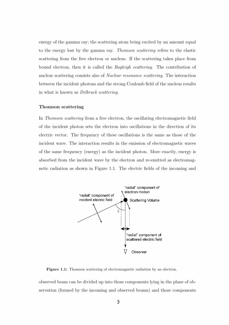
of the same frequency (energy) as the incident photon. More exactly, energy is
absorbed from the incident wave by the electron and re-emitted as electromag-
netic radiation as shown in Figure 1.1. The electric fields of the incoming and
Figure 1.1: Thomson scattering of electromagnetic radiation by an electron.
observed beam can be divided up into those components lying in the plane of ob-
servation (formed by the incoming and observed beams) and those components
Administrator
3

perpendicular to that plane. Those components lying in the plane are referred
to as ”radial” and those perpendicular to the plane are ”tangential”, since this
is how they appear to the observer. The diagram shows the radial component
of the incident electric field causing a component of motion of the charged par-
ticles at the scattering point which also lies in the plane of observation. The
amplitude of the wave observed will be proportional to the cosine of χ, the angle
between the incident and observed beams. The intensity, which is the square of
the amplitude, will then be diminished by a factor of cos2χ. It can be seen that
the tangential components (perpendicular to the plane of the diagram) will not
be affected in this way. If the charged particle in question is an electron, the well
known Thomson scattering cross section is given by
σThomson =8π
3(e2/4πε0mec
2) = 6.65× 10⁻²⁹m2. (1.1)
The quantity (e2/4πε0mec2) = 2.8×10⁻¹⁵m is called the classical electron radius
(it is the radius of spherical shell of total charge whose electrostatic energy equals
the rest mass energy of the electron). Electron, thus acts as a scatterer, rather
like a solid sphere whose radius is of order the classical electron radius. Since
this radius is extremely small, it is clear that scattering of radiation by a single
electron (or any other charged particle) is a very weak process.
Rayleigh Scattering
Rayleigh scattering is essentially Thomson scattering on electrons bound in an
atomic potential, including the effects of resonances and phase coherence between
multiple electrons [2]. Here, the photons are scattered by the bound electrons in
a process where the atom is eventually neither excited nor ionized. The atom is
therefore left in its ground state itself after the scattering process. The scattering
from different parts of the atomic cloud of electrons combine in phase to give
coherent scattering. This process mainly occurs at low energies and for large
Z values where the electron binding energies influence the Compton effect. In
this scattering process, the energy (and therefore the wavelength) of the incident
Administrator
Administrator
4
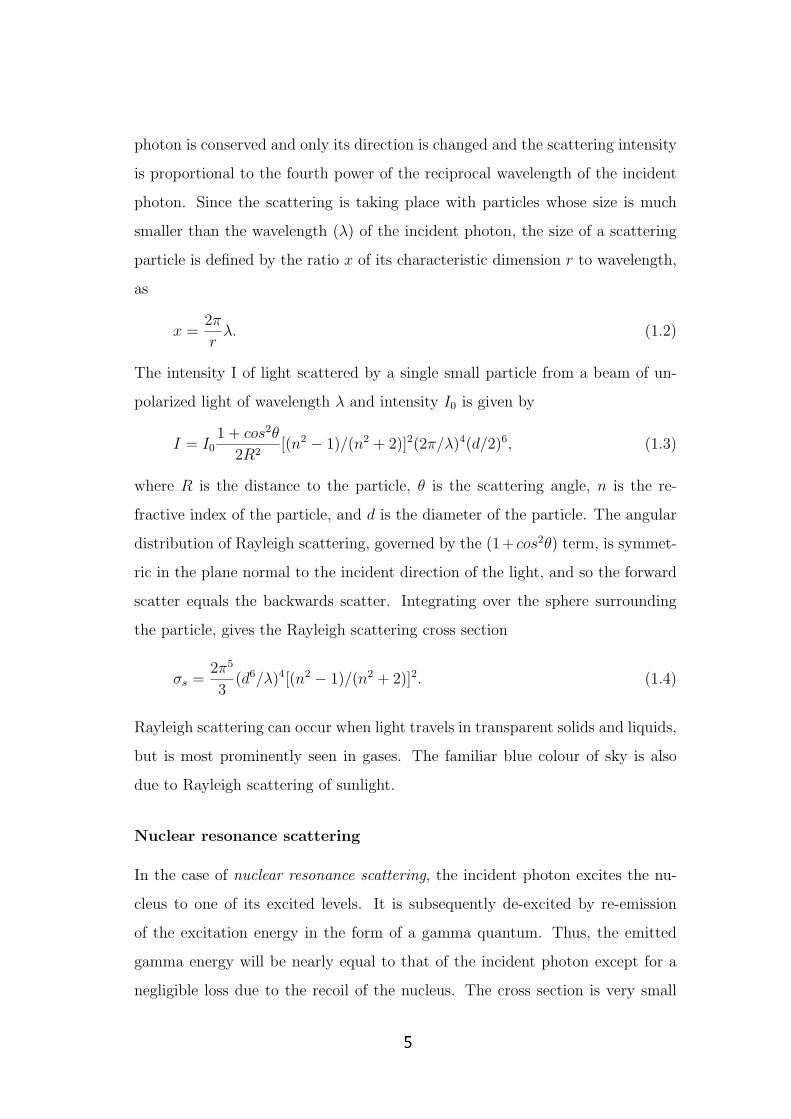
photon is conserved and only its direction is changed and the scattering intensity
is proportional to the fourth power of the reciprocal wavelength of the incident
photon. Since the scattering is taking place with particles whose size is much
smaller than the wavelength (λ) of the incident photon, the size of a scattering
particle is defined by the ratio x of its characteristic dimension r to wavelength,
as
x =2π
rλ. (1.2)
The intensity I of light scattered by a single small particle from a beam of un-
polarized light of wavelength λ and intensity I0 is given by
I = I01 + cos2θ
2R2[(n2 − 1)/(n2 + 2)]2(2π/λ)4(d/2)6, (1.3)
where R is the distance to the particle, θ is the scattering angle, n is the re-
fractive index of the particle, and d is the diameter of the particle. The angular
distribution of Rayleigh scattering, governed by the (1+ cos2θ) term, is symmet-
ric in the plane normal to the incident direction of the light, and so the forward
scatter equals the backwards scatter. Integrating over the sphere surrounding
the particle, gives the Rayleigh scattering cross section
σs =2π5
3(d6/λ)4[(n2 − 1)/(n2 + 2)]2. (1.4)
Rayleigh scattering can occur when light travels in transparent solids and liquids,
but is most prominently seen in gases. The familiar blue colour of sky is also
due to Rayleigh scattering of sunlight.
Nuclear resonance scattering
In the case of nuclear resonance scattering, the incident photon excites the nu-
cleus to one of its excited levels. It is subsequently de-excited by re-emission
of the excitation energy in the form of a gamma quantum. Thus, the emitted
gamma energy will be nearly equal to that of the incident photon except for a
negligible loss due to the recoil of the nucleus. The cross section is very small
Administrator
5

unless the gamma energy happens to be close to one of the energy levels of the
nucleus. It has a clear resonance behaviour with full width at half maximum
(FWHM) characterized by the energy width of the nuclear level with energy E0
involved in the process. The cross section in this case has an energy dependence
as follows:
σNR = λ2ΓΓγ/4π[(E0 − Eγ)2 + (Γ/2)2]. (1.5)
Here, λ is the incident photon wavelength, Γ is the total width of the nuclear level,
Γγ is the partial width for gamma decay of the excited state of energy and Eγ
is the photon energy. Due to the comparatively narrow widths of nuclear levels
at low excitations, the chance of overlap of the incident gamma energy with the
excitation energy of the target nucleus is very rare indeed. Therefore, unless there
is an accidental overlap of Eγ with E0, the contribution from nuclear resonance
scattering process to the observed elastic scattering of the incident photons is
negligible. Apart from the above mentioned nuclear resonance scattering process,
there is yet another resonance process of nuclear scattering which the incident
photon can undergo. A strong photon absorption is observed for many nuclei
near gamma energies given by
E0 = εA−1/3 (1.6)
where ε varies between 70 to 80 MeV and A is the atomic number of the ele-
ment. The scattering then corresponds to the Giant Dipole Resonance scattering
(GDR). The process is appreciable only at energies above 10 MeV or so. How-
ever, the resonance being very broad, the low energy tail of the resonance peak
can contribute to the elastic scattering at lower energies also.
Delbruck scattering
Delbruck scattering, also known as the elastic nuclear potential scattering is due
to virtual electron pair formation in the nuclear Coulomb field. The actual
mechanism of the process involves the absorption of the incident photon by an
Administrator
6

electron in the negative energy state, followed by the creation of a electron-
positron pair and subsequent annihilation of the pair to give a scattered photon
of exactly the same energy as the incident photon. The cross section is very
small at low gamma energies below 1 MeV, but increases at higher energies. It
has a dependence on the atomic number of the scatterer. The real part of the
scattering amplitude is related to virtual pair production in the intermediate
state. The imaginary part of the scattering amplitude corresponds to real pair
production in the intermediate state. Of course, real pair production is possible
only if the incident photon energy is above the pair production threshold of 1.022
MeV.
1.1.2 Inelastic scattering
In particle physics and chemistry, inelastic scattering is a fundamental scattering
process in which the kinetic energy of an incident particle is not conserved. In
this scattering process, the energy of the incident particle is lost or gained. When
a photon is the incident particle, the inelastic scattering process is called Raman
scattering wherein the incident photon interacts with matter (gas, liquid, and
solid) and the frequency of the photon is shifted to blue or red. The blue shift
can be observed when the internal energy of matter is transferred to the photon;
this process is called anti-Stokes Raman scattering. The red shift can be observed
when a part of the energy of the photon is changed to the internal energy of the
interacting matter; this process is called Stokes Raman scattering.
Inelastic scattering also occurs in the interaction between an electron and a
photon. When a high energy photon collides with a free electron and transfers
energy, the process is called Compton scattering. Furthermore, when an electron
with relativistic energy collides with an infrared or visible photon, the electron
gives energy to the photon; this process is called inverse-Compton scattering.
Administrator
7
Compton scattering
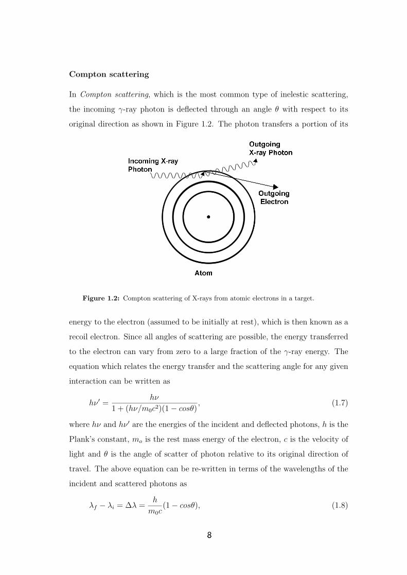
In Compton scattering, which is the most common type of inelestic scattering,
the incoming γ-ray photon is deflected through an angle θ with respect to its
original direction as shown in Figure 1.2. The photon transfers a portion of its
Figure 1.2: Compton scattering of X-rays from atomic electrons in a target.
energy to the electron (assumed to be initially at rest), which is then known as a
recoil electron. Since all angles of scattering are possible, the energy transferred
to the electron can vary from zero to a large fraction of the γ-ray energy. The
equation which relates the energy transfer and the scattering angle for any given
interaction can be written as
hν ′ =hν
1 + (hν/m0c2)(1− cosθ), (1.7)
where hν and hν ′ are the energies of the incident and deflected photons, h is the
Plank’s constant, mo is the rest mass energy of the electron, c is the velocity of
light and θ is the angle of scatter of photon relative to its original direction of
travel. The above equation can be re-written in terms of the wavelengths of the
incident and scattered photons as
λf − λi = ∆λ =h
m0c(1− cosθ), (1.8)
Administrator
8
where h is the Planck’s constant. This shift in wavelength is called the Compton
shift and is seen to be independent of the wavelength of the incident radiation.
The cross section for the Compton scattering from a free electron has been de-
rived by Klein and Nishina [3] based on Dirac’s relativistic theory of the electron.
Their result is embodied in the famous Klein-Nishina formula,
dσ
dΩ= r2
0[1
1 + α(1− cosθ)]3[
1 + cos2θ
2][1+
α2(1− cosθ)2
(1 + cos2θ)[1 + α(1− cosθ)]],(1.9)
where α ≡ hν/m0c2 and r0 is the classical electron radius.
1.2 Absorption
If the radiation is substantially or completely extinguished by the interaction
(losing a significant proportion of its energy), the process is known as absorption.
In some contexts, absorption is considered to be merely an extreme form of
inelastic scattering. Generally speaking, in classical physics, absorption and
scattering tend to be treated as different phenomena, while in quantum physics
absorption is treated as a form of scattering via the S-matrix. To be precise,
absorption cannot occur without some degree of scattering, and scattering is
rarely completely elastic in a microscopic scale.
1.2.1 Photoelectric effect
In the photoelectric absorption process, an incoming gamma photon interacts
with and transfers its energy to an atomic electron, ejecting that electron from
the atom as shown in Figure 1.3. The kinetic energy (Ee) of the resulting photo-
electron is equal to the energy of the incident gamma photon minus the binding
energy (Ee) of the electron and is given by
Ee = hν − Eb. (1.10)
The photoelectric interaction is with the atom as a whole and cannot take place
with free electrons. For γ-rays of sufficient energy, the most probable origin of
Administrator
9

Figure 1.3: One of the atom’s electrons absorbs the X-ray photon and is tossedcompletely out of the atom.
the photoelectron is the most tightly bound shell (K-shell) of the atom. The
probability of photoelectric absorption per atom over all ranges of Eγ and Z s
given by
τ = Const.× Zn
E3γ
, (1.11)
where the exponent n varies between 4 and 5 over the γ-ray energy region of in-
terest. Because of the strong dependence of photoelectric absorption probability
on the atomic number Z, high Z materials are preferred for gamma ray detectors.
The strong inverse dependence of τ on the γ-ray energy makes the photoelectric
effect the predominant mode of interaction for the low energy γ-rays and X-rays.
Absorption edges
In the plot of mass attenuation coefficient, with incident γ-ray energy, disconti-
nuities in the curve or ”absorption edges” appear at energies which correspond
to the binding energies of the electrons in the various shells of the absorber atom.
The edge lying highest in energy therefore corresponds to the binding energy of
K shell electron. For γ-ray energies slightly above the edge, the photon energy is
just sufficient to undergo a photoelectric interaction in which K-electron is ejected
from the atom. For gamma ray energies slightly below the edge, this process is
Administrator
10

Figure 1.4: Energy dependence of the various gamma ray interaction processes inFe.
no longer possible and therefore the interaction probability drops abruptly as
illustrated in Figure 1.4. Similar absorption edges occur at lower energies for the
L, M,..... electron shells of the atom also.
1.2.2 Pair production
In pair production, the entire gamma energy is completely absorbed in the ma-
terial and used up in the creation of an electron-positron pair. The process can
be represented as follows.
γ −→ e− + e+. (1.12)
The energy balance equation can be written as
Eγ = 2m0c2 + T−
e + T+e , (1.13)
where m0 is the rest mass of the electron, T−e and T+
e are the kinetic energies of
the electron and positron respectively. It is thus seen that pair production has a
threshold energy given by 2m0c2 = 1.022 MeV. Thus the process is possible only
for gamma energies above 1.022 MeV. Above this threshold, the cross section for
Administrator
11

the process increases and at higher energies, pair production is the predominant
interaction.
The relative importance of the three processes namely photoelectric absorp-
tion, Compton scattering and pair production for different absorber materials
and gamma ray energies is conveniently illustrated in Figure 1.5. The line at
the left represents the energy at which photoelectric absorption and Compton
scattering are equally probable as a function of the atomic number [4]. The line
Figure 1.5: The energy dependence of the three major types of gamma ray interac-tions. The lines show the values of Z and hν for which the two neighbouring effectsare just equal.
at the right represents the energy at which Compton scattering and pair produc-
tion are equally probable. Three areas are thus defined on the plot within which
photoelectric absorption, Compton scattering and pair production dominate.
1.3 Attenuation
1.3.1 Beer-Lambert Formula
Attenuation is the reduction in intensity of the primary X-ray beam as it tra-
verses matter by either absorption or scattering. When gamma rays pass through
Administrator
12

matter, their intensity is attenuated according to the familiar exponential law.
This means that a beam of radiation of a definite energy Eγ having intensity
I0, passing through an absorber of thickness x will have a transmitted intensity
given by
I(x) = I0e−µx, (1.14)
where µ is a constant characterizing the medium for that gamma energy. It
is called the linear attenuation coefficient. It represents sum of the probability
per unit path length that the γ ray photon is removed from the beam due to
photoelectric Compton scattering and pair production interactions. i.e.,
µ = τ(photoelectric) + σ(Compton) + κ(pair). (1.15)
If x is in cm, µ will be expressed in units of cm−1. The mass attenuation coef-
ficient is expressed as (µ/ρ), where ρ is the density of the medium. It is more
common to express the thickness of the absorber as t = xρ, and the mass at-
tenuation coefficient in units of cm2/g. The absorption law can be rewritten
as
I(t) = I0e(−µ/ρ)t, (1.16)
which is known as Beer-Lambert formula. The exponential decrease of the
gamma ray intensity arises from the fundamental nature of the interactions of the
gamma rays with matter. When a gamma ray photon undergoes an interaction,
it is either absorbed completely or scattered away from the incident direction.
The probability for the interaction essentially depends on the number of interac-
tion centers in the path of the gamma rays as well as on the probability for the
interaction. If the incident gamma ray beam, having I photons traverses through
a certain thickness x of the medium, let dI photons undergo interactions with
the medium thereby getting removed from the direct beam. Then
dI
I=
N0ρσdx
A, (1.17)
where σ is the total cross section for all interactions and A is the mass number
of the element of the medium (considering that the medium contains only one
Administrator
13

element). N0 is the Avogadro number. Letting µ = (N0ρσ)/A and integrating
the above equation, we get back to eq.(1.16).
When a beam of gamma rays passes through an absorber, the gamma ray
photons interact with the atoms individually and are either absorbed (via pho-
toelectric effect and pair production) or scattered away from the beam. The
intensity of the transmitted beam is consequently attenuated. The total cross
section for attenuation of the incident beam of gamma rays is the sum of the
cross sections per atom for all the three processes. Therefore, the total cross
section is given by
σ = στ + σC + σPP . (1.18)
If N is the number of atoms per unit volume of the absorber, the linear absorption
coefficient can be written as
µ = Nσ. (1.19)
1.3.2 Mixture rule
The linear absorption coefficient depends on the gamma ray energy Eγ, the
atomic number Z and the density of the absorber medium. On the other hand,
the mass attenuation co-efficient is independent of the absorber density. It de-
pends only on the number of interacting centers in the path of the photon beam.
Thus, for a mixture or a compound of different elements, the mixture rule [5]
can be applied. The mass attenuation coefficient of a compound or mixture,
according to the rule is
(µ/ρ) =∑
i
wi(µ/ρ)i, (1.20)
where wi is the proportion by weight of the element with mass absorption coef-
ficient (µ/ρ)i.
Administrator
14
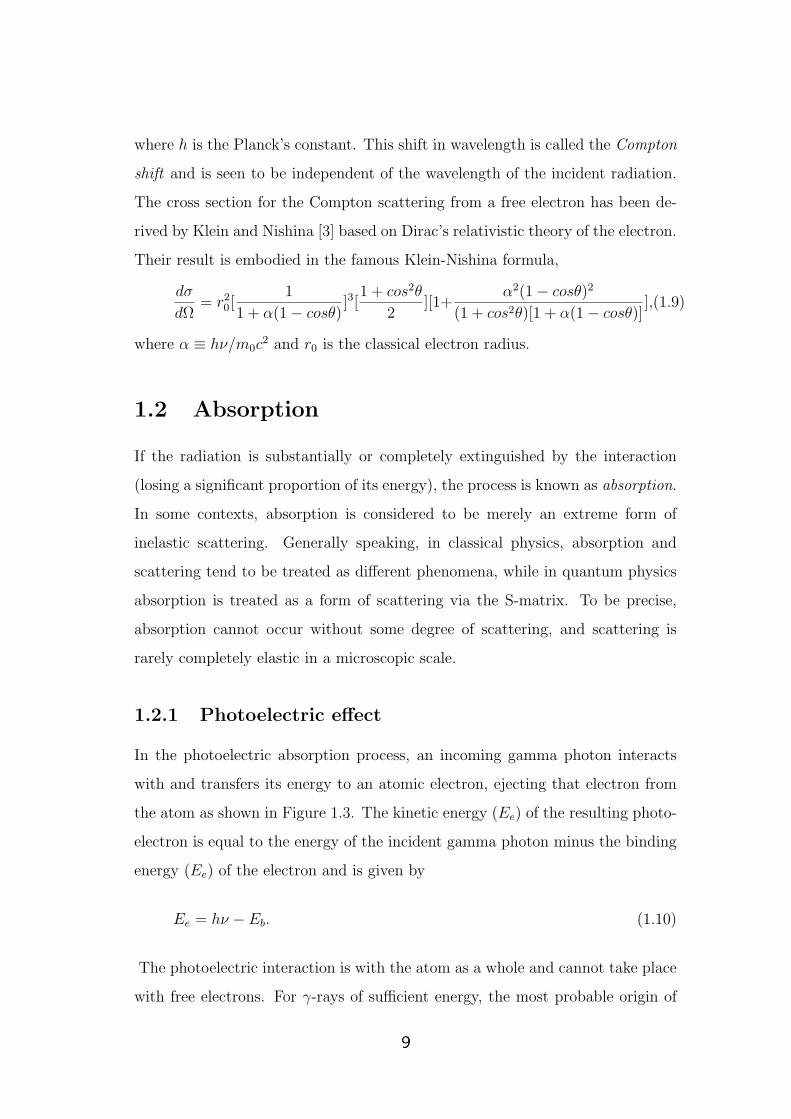
1.3.3 Narrow beam and broad beam geometries
In order to find the value of µ, we have to know the initial intensity of the incident
gamma ray photon, I0. The absorption of gamma rays depends strongly upon its
energy and the atomic number of the absorber. The exponential absorption law
(eq.1.16) is difficult to observe experimentally, because of the detection of the
gamma rays scattered from the absorber and other surrounding materials along
with the transmitted beam. The X-rays emitted from the absorber also affect the
measurements. In order to reduce the above mentioned problem we have to use a
special geometry called narrow beam geometry set up. This arrangement reduces
the solid angle subtended by the detector at the center of the target by use of
suitable shielding and collimation. It prevents the coherently and incoherently
scattered photons from reaching the detector. Hence only the radiation coming
out from the target without any interaction will reach the detector. The Figure
1.6(a) below illustrates the narrow beam geometry compared to broad beam
geometry.
Figure 1.6: (a)-Narrow beam geometry (b)-Broad beam geometry; S-source, C-Collimator, A-Absorber, D-Detector.
Whenever a significant fraction of the scattered photons and the secondary
photons can reach the detector, the arrangement is called broad beam or poor
geometry, as shown in Figure 1.6(b). Here, there is no shielding for either
Administrator
15

the source or the detector. The absorber to detector distance is comparatively
smaller. Scattered radiation from the absorber can reach the detector within
a reasonably large angle (the so called in-scattering angle). Thus, we will be
detecting not only the purely transmitted photons but also those which have
undergone scattering interactions. As a result the value of the measured at-
tenuation coefficient will be smaller than the true value. Of course, one can
still extract the true value of the attenuation coefficient provided a correction is
applied for the in-scattering.
On the other hand, in the narrow beam geometry set up depicted in Figure
1.6(a), both the source and the detector are well shielded and the incident and
transmitted beams are well collimated. The distances involved are also larger
as compared to the broad beam geometry. The in-scattering angle is thereby
minimized and the contribution of the scattered radiation will be negligible.
Hence we get a value for the attenuation coefficient very near to the true value.
1.3.4 Buildup factor
In the broad beam geometry, the transmitted intensity of the gamma rays will
not follow the normal exponential attenuation as given by eq.(1.16). Instead, we
get the following equation
I(t) = B(t, Eγ)I0e(−µ/ρ)t. (1.21)
Here, B(t, Eγ) is a factor which accounts for the in-scattering. It depends on the
in-scattering angle as well as on the absorber thickness and is called the buildup
factor. The exponential term is retained to describe the major variation in the
γ-ray counting rate with absorber thickness and the buildup factor is introduced
as a multiplicative correction. The magnitude of the build up factor depends on
the type of γ-ray detector used, because this will affect the relative weightage of
the direct and scattered γ-rays. (With detector that responds only to the direct
γ-rays, the build up factor is unity.) The build up also depends on the specific
geometry of the experiment. As a rule of thumb, the build up factor of thick slab
Administrator
16

absorbers tends to be about equal to the thickness of the absorber measured in
units of mean free path of the incident γ-rays, provided the detector responds to
broad range of γ-ray energies.
1.4 Proton Induced X-ray Emission(PIXE)
Proton induced X-ray emission (PIXE) technique [6, 7]relies on the analysis of
the energy spectra of characteristic X-rays emitted from a sample bombarded
with 1-3 MeV protons. The technique is widely used in different areas due to
its possibilities in performing fast multi-elemental and nondestructive analysis
of different kinds of samples. However, to convert the X-ray yields of different
constituents of a thick sample to their concentrations, the X-ray mass attenuation
coefficients are needed [8]. Knowledge of mass attenuation coefficients is also
necessary in PIXE practice [9] to calculate the transmission of X-ray filters and
also for an accurate Si(Li) detector efficiency determination [10], especially for
low-energy X-rays (below 5 keV).
PIXE analysis consists of two parts. The first is to identify the atomic species
in the target from the energies of the characteristic peaks in the X-ray emission
spectrum and the second part is to determine the amount of a particular ele-
ment present in the target from the intensity of its characteristic X-ray emission
spectrum. This normally requires knowledge of the ionization cross-sections,
fluorescence yields and absorption coefficients. In carrying out attenuation mea-
surements in the X-ray region using PIXE facility, the samples are kept in a
vacuum chamber are irradiated with 1− 3 MeV proton beam and the character-
istic X-ray spectra are registered with a Si(Li) semiconductor detector coupled
to standard electronics and a PC based multichannel analyzer. The spectra
are analyzed by noting the component peaks of the X-ray spectrum for each
absorber.
The major advantage of the PIXE technique is a low background yielding
high sensitivity for trace element determination. The elements which are present
Administrator
17

in the level of µg/g (ppm) or less generally considered as trace elements. Investi-
gations for the determination of trace elements in biological specimen [11, 12] and
also in environmental samples [13] using PIXE has been the subject of numerous
research works for over 25 years.
1.5 Anomalous scattering factors
The effects of anomalous scattering which manifest themselves most when the
incident X-ray energy approaches the absorption edge energies of an atom are de-
scribed mathematically by two correction terms which are applied to the normal
atomic form factor or Thompson scattering factor f0. The modified scattering
factor is given by
f = f0 + f′+ if ” (1.22)
where the first term f0 is Thomson scattering factor, f′
and f ” are real and
imaginary parts of anomalous scattering factors also known as the dispersion
corrections to f0. They give the deviation of the forward Raleigh scattering
amplitude from the form factor. The optical theorem [14] demonstrates that the
imaginary term f ” is directly related to the atomic cross section as
f ” =E
2hcr0
σtot. (1.23)
where r0 = e2
4πε0mc2is the classical electron radius, also known as the Compton
radius or the Thomson scattering length which is based on a classical relativis-
tic model of the electron. As in other resonance phenomena such as dielectric
susceptibility, the real part of the dispersive term is related to the imaginary
part by a Kramers-Kronig (K-K) transformation [15, 16]. In the case of X-ray
scattering, the K-K transform takes the following form
f′(Eo) =
2
π
∫ ∞
0
Ef ”(E)
E20 − E2
dE (1.24)
In the energy region of current interest, if we neglect the spin flip processes, the
f′and f ” are connected by the modified Kramers-Kronig transform [17, 18, 19]
Administrator
18
as given by
f′(Eo) = f ′(∞)− 2
πP
∫ ∞
0
Ef ”(E)
E20 − E2
dE (1.25)
where f ′(∞) is the high-energy limit and P is the Cauchy principal value of the
dispersion integral, E0 is the energy of interest. Thus, it is possible to determine
the dispersion corrections f′
and f ” from a set of photoeffect cross sections
using equations 1.24 and 1.25. The anomalous scattering factors are very much
in need when performing Multiple wavelength Anomalous Diffraction (MAD)
experiments.
1.6 XCOM
Berger and Hubbell [20, 21] developed a computer program, called XCOM, and
a database which can be used to calculate cross sections and attenuation coef-
ficients for any element, compound or mixture, at energies from 1 to 100 GeV.
This, much used program has since undergone a number of updates, and is
now also available in a Web version [22]. XCOM can generate cross sections
and attenuation coefficients on a standard energy grid, spaced approximately
logarithmically, or on a grid selected by the user, or for a mix of both grids.
The program provides total cross sections and attenuation coefficients as well as
partial cross sections for incoherent scattering, coherent scattering, photoelec-
tric absorption, and pair production. For compounds, the quantities tabulated
are partial and total mass interaction coefficients. Total attenuation coefficients
without the contribution from coherent scattering are also given, because they
are often used in gamma-ray transport calculations. Written in 1987, XCOM
was intended to be compiled and linked on a main-frame computer, or run on
a personal computer using the DOS operating system. The attenuation mea-
surements in the present work on rare earth elements and thin foils obtained
by using 241Am source and Proton induced x-ray emission are compared with
XCOM values and are plotted in the forthcoming chapters.
Administrator
19

1.7 The present work
The broad aim of the present work is threefold :
I. Study X-ray attenuation of few rare earth elements with 62 ≤ Z ≤ 68, by
Compton scattering method.
We have carried out photon attenuation measurements at several energies in the
range from 49.38 keV to 57.96 keV around the K-absorption edges of the rare
earth elements Sm, Eu, Gd, Tb, Dy and Er using 59.54 keV γ-rays from 241Am
(300mCi) source after Compton scattering from an aluminium target. Pellets
of oxides of the rare earth elements were chosen as mixture absorbers in these
investigations. Under the narrow beam good geometry set up, the transmitted
γ-rays were detected by an HPGe detector.
II. Study X-ray attenuation of few elements with 40 ≤ Z ≤ 46 by using:
(a) Radioactive source and
(b) Proton Induced X-ray Emission.
Mass attenuation coefficients (µ/ρ) for elements Zr, Nb, Mo and Pd around
their K-edges were measured at 14 energies in the range 15.744 − 28.564 keV
using secondary γ-ray excitation from thin Zr, Nb, Mo, Rh, Pd, Cd and Sn foils.
These measurements were carried out at the Kα and Kβ energy values of the
target elements by two different techniques.
In the PIXE method, 2 MeV proton excited X-rays were used and detected by a
Si(Li) detector of resolution 175 eV at 5.9 keV. In the second case, X-rays excited
from the targets by 59.54 keV photons were detected by an HPGe detector.
III. Obtain anomalous scattering factors (dispersion corrections) to the for-
ward Raleigh scattering amplitude for the elements with 40 ≤ Z ≤ 46. Atomic
photoeffect being an important process contributing to the total attenuation of
the incident photon beam in the low energy region, our experimental data is
used to find the anomalous scattering factors to the forward Raleigh scattering
amplitude to the elements Zr, Nb, Mo and Pd.
Administrator
20
References
[1] U. Fano, Nucleonics, 11(8):8(1953); 11(9):55(1953). [Chap.23, Introd.; Chap.
25, Secs. 1,3]
[2] L. Kissel, Radiat. Phys. Chem. 59, 185 (2000).
[3] O. Klein and Y. Nishina, Z. Physik, 52, 853 (1929).
[4] G. F. Knoll, Radiation Detection and Measurement John Wiley and Sons,
New York, (1970).
[5] R. D. Evans, The Atomic nucleus, Mcgraw-Hill, New York, (1955).
[6] S. A. E. Johansson and J. L. Campbell, PIXE, A Novel Technique for Ele-
mental Analysis, Wiley, Chichester UK, (1988).
[7] V. Havranek, V. Hnatowicz, J. Kvitek and I. Obrusnik, Nucl. Instr. and
Methods. B85, 637 (1994).
[8] J. L. Campbell and J. A. Cookson, Nucl. Instr. and Methods B3, 185 (1984).
[9] K. M. Varier and M. P. Unnikrishinan, Phys.Rev.A 33, 2382 (1986).
[10] M. Pajek, A. P. Kobzev, R. Sandrik, R. I. khamov and S. Khusumurodov,
Nucl. Instr. and Methods B 42, 346 (1989).
[11] K. K. Abdullah, K. M. Varier, R. E. Manikandan, Ananth N. Rao, P. Magu-
dapathy and K. G. M. Nair, Annual Conference on Medical Physics and Ra-
diation Safety, 23-24 Sept 2006 VIT, Vellore, Tamil Nadu.
21

[12] K. K. Abdullah, K. M. Varier , R. E. Manikandan, Lulu Mathews, P. Magu-
dapathy and K. G. M. Nair, Annual Conference on Medical Physics and Ra-
diation Safety, 23-24 Sept 2006 VIT, Vellore, Tamil Nadu.
[13] K. K. Abdullah, R. E. Manikandan, P. Magudapathy, K. G. M. Nair and
K. M. Varier, Indian Particle Accelerator Conference, InPAC-2006 Nov 1-4,
2006 BARC-TIFR, Mumbai.
[14] R. W. James, The Optical Principles of the Diffraction of X-rays, G. Bell
and sons Ltd, London, (1969).
[15] H. A. Kramers, Cong. Intern. Fisica, (Transactions of Volta Centenary
Congress) Como, 2, 545 (1927).
[16] R. de L. Kronig, J. Opt. Soc. Am. 12, 547(1926).
[17] B. Zhou, L. Kissel and R. H. Pratt, Nucl. Instrum. Methods B 66, 307
(1992).
[18] B. L. Henke, P. Lee, T. J. Tanaka, R. L. Shimambukuro and B. K. Fujikawa,
At. Data Nucl. Data Tables 27, 1 (1982);
[19] B. L. Henke, E. M. Gullikson and J. C. Davis, At. Data Nucl.Data Tables
54, 181(1993).
[20] J. H. Hubbell, Natl. Stand. Ref. Data Ser. 29 (1969).
[21] M. J. Berger and J. H. Hubbell, National Bureau of Standards (former name
of NIST), Gaithersburg, MD, ”XCOM: Photon Cross Sections on a Personal
Computer,” NBSIR 87-3597.
[22] M. J. Berger and J. H. Hubbell, NIST Standard Reference Database 8, Ver-
sion 1.1.2, National Institute of Standards and Technology, Gaithersburg, MD
(1999).
Administrator
22