
Intentionally Blank - Sisteme de incalzire|Filtre si ... · 4 VAL PRODUCTS, INC. WARRANTIES...
51
PolAIR® High Pressure Fog System U:\MANUALS \990000\990049 JDS 11-30-2011
Transcript of Intentionally Blank - Sisteme de incalzire|Filtre si ... · 4 VAL PRODUCTS, INC. WARRANTIES...

1
PolAIR® High Pressure Fog System
U:\MANUALS \990000\990049JDS 11-30-2011

2
Intentionally Blank

3
Table of Contents
Table of Contents.......................................................................................................................................................................3Warranty........................................................................................................................................................................4-5Symbols............................................................................................................................................................................6Features and Benefits.......................................................................................................................................................7Product Introduction........................................................................................................................................................8System Components.........................................................................................................................................................9Commonly used Compression Fittings.......................................................................................................................10-11Typical Compression Union Assembly.............................................................................................................................12Assembly and Installation ..............................................................................................................................................13Intentionally Blank..........................................................................................................................................................14Assembly Guidelines.......................................................................................................................................................15Suspension Cable System Installation........................................................................................................................16-17Atomization Nozzle Line (ANL) and Mainline Tubing......................................................................................................17First Time Start-Up, Seasonal Start-Up and Winterizing Procedures .........................................................................18-22Preventative Maintenance - General..............................................................................................................................23Maintenance for the BR5 and BR10 Regulators...............................................................................................................24PolAIR® Nozzle / Check Valve Assembly CARE and Cleaning.....................................................................................25-27PMDVADJ Automatic Drain Valve....................................................................................................................................28Drain Valve Line Assembly...............................................................................................................................................29Intentionally Blank..........................................................................................................................................................30Appendix 1 - PMDVADJ Automatic Drain Valve Exploded Drawing and Parts List.........................................................31Appendix 2 - Filter Kits Parts List...................................................................................................................................32Appendix 3 - 10-30 GPM Filter Kit Exploded Drawing and Parts List.............................................................................33Appendix 4 - Nozzle Exploded Drawing.........................................................................................................................34Appendix 5 - Nozzle Assemblies and Spare Parts List....................................................................................................35Appendix 6 - Accessory Parts List...................................................................................................................................36Appendix 7 - Control 400HC ..........................................................................................................................................37Appendix 8 - PolAIR® EA-010-001 Control Exploded Drawing.......................................................................................38
Appendix 9 - VE-010-001 PolAIR® 400 HC Control Parts List.........................................................................................39Appendix 10 - Layout Option Examples.......................................................................................................................40-48Appendix 11-PolAIR® High Pressure Fog System Poultry - Design Request Sheet.....................................................49-50Appendix 12 - Customer Service.......................................................................................................................................51

4
VAL PRODUCTS, INC. WARRANTIES
Val-co®MANUFACTURED PRODUCTS OTHER THAN EXTENDED WARRANTY PRODUCTSVal Products, Inc. (Val Products) warrants to the original purchaser that Val Products’ manufactured prod-ucts (other than the products subject to an extended warranty set forth below) will be free of defects in material and workmanship for a period of one (1) year from and after the date of original purchase and when used in a usual and customary fashion. If Val Products is notified that such a defect exists within one year of the original purchase date and, upon inspection, agrees that the product is defective, Val Products will, at its option, (a) repair or replace (FOB Val Products’ plant) the defective product, or (b) refund to the original purchaser the original purchase price paid for the defective product less any installation, shipping, or other charges associated with the original purchase. All defective products must be returned to a Val Products designated location for evaluation. Val Products’ determination as to whether the product is defective is final. See the General Conditions and Limitations set forth below.
NIPPLE DRINKERS EXTENDED WARRANTYVal Products, Inc. (Val Products) agrees to the following extended warranty with respect to VR Series and VL Series Nipple Drinkers manufactured by Val Products: VR Series and VL Series Nipple Drinkers that prove to be defective in workmanship or material and become unusable within a period of five (5) years from and after the date of original purchase will be repaired or replaced, at Val Products’ option, at no charge (excluding labor of removal and installation), FOB Val Products’ plant. VR Series and VL Series Nipple Drink-ers which prove to be defective in workmanship or material and become unusable after five (5) years but within ten (10) years of the date of original purchase will be repaired or replaced, at Val Products’ option, at a pro rated cost basis (excluding labor of removal and installation) to the original purchaser, FOB Val Products’ plant, on the following basis: Year six (6), customer pays 50% of the current price, year seven (7), customer pays 60% of the current price, year eight (8), customer pays 70% of the current price, year nine (9), customer pays 80% of the current price, and year ten (10), customer pays 90% of the current price. All defective Nipple Drinkers must be returned to a Val Products’ designated location for evaluation. Val Pro-ducts’ determination as to whether the product is defective and unusable is final. See the General Condi-tions and Limitations set forth below.
FIBERGLASS FAN HOUSINGS EXTENDED WARRANTYVal Products, Inc. (Val Products) agrees to the following extended warranty with respect to the fiberglass fan housings manufactured by Val Products on Val-co® PMC Power Miser 12”, 16”, 21”, 24”, 36”, 48”, and 50” Fiberglass Fans that prove to be defective in workmanship or material and become unusable over the life of the structure where the Val-co®Fiberglass Fan was originally installed after original purchase, provid-ed that the fan has remained undisturbed in its original installation location, will be repaired or replaced, at Val Products’ option, at no charge (excluding labor of removal and installation and shipping), FOB Val Products’ plant. All defective fan housings must be returned to a Val Products’ designated location for evaluation. Val Products’ determination as to whether the product is defective and unusable is final. See the General Conditions and Limitations set forth below.
FIBERGLASS FAN MOTORS EXTENDED WARRANTYVal Products, Inc. (Val Products) agrees to the following extended warranty with respect to the fiberglass fan motors included as original equipment on Val-co® PMC Power Miser 12”, 16”, 21”, and 24” Fiberglass Fans manufactured by Val Products that prove to be defective in workmanship or material and become
Warranty

5
un-usable within a period of two (2) years from and after the date of original purchase will be repaired or replaced, at Val Products’ option, at no charge (excluding labor of removal and installation and shipping), FOB Val Products’ plant. All defective fan motors must be returned to a Val Products’ designated location for evaluation. Val Products’ determination as to whether the product is defective and unusable is final. See the General Conditions and Limitations set forth below.
General Conditions and Limitations Applicable to All Val Products, Inc. (Val Products) Warranties, Includ-ing Extended Warranties
1. The Product must be installed and operated in accordance with instructions published by Val Pro ducts or the warranty will be void.2. Warranty will be void if all components of the product or system are not original equipment supplied by the manufacturer.3. Products not manufactured by Val Products and supplied by outside manufacturers (such as, but not limited to, certain electrical motors, certain controls, gas valves, etc.) are warranted separately by the respective manufacturer and only to the extent of the manufacturer’s warranty.4. Warranty applies only to products used in applications as originally intended by Val Products – other applications in industry or commerce are not covered by the Warranty. Val Products’ pro- ducts are expressly not designed or authorized for use in any applications where intended to Sus tain or support human life or any other application where the failure of the product could result in personal injury or death.5. Malfunctions resulting from misuse, abuse, mismanagement, negligence, alteration, accident, lack of proper maintenance, lightening strikes, electrical power surges, or electrical power interruption shall not be considered defects under the Warranty. Corrosion, material deterioration and/or equip ment malfunction caused by or consistent with the excessive additions of chemicals, minerals, sedi ments or other foreign elements with the product shall not be considered defects under the War ranty.
6. VAL PRODUCTS WILL NOT, UNDER ANY CIRCUMSTANCES, BE LIABLE FOR ANY KIND OF SPECIAL, INCIDENTAL, CONSEQUENTIAL, OR CONTINGENT DAMAGES INCLUDING, BUT NOT LIMITED TO, LOST OR DAMAGED PRODUCT, GOODS OR LIVESTOCK, COSTS OF TRANSPORTATION, LOST SALES, LOST ORDERS, LOST INCOME, INCREASED OVERHEAD, LABOR AND INCIDENTAL COSTS AND OPERATIONAL INEFFICIENCIES. IN NO EVENT SHALL THE WARRANTY LIABILITY EXCEED THE INVOICED PRICE OF THE PRODUCT TO THE ORIGINAL PURCHASER.
7. THE WARRANTIES SET FORTH ABOVE CONSTITUTE VAL PRODUCTS’ ENTIRE AND SOLE WARRANTY. VAL PRODUCTS EXPRESSLY DISCLAIMS ANY AND ALL OTHER WARRANTIES INCLUDING, BUT NOT LIMITED TO, ANY AND ALL OTHER EXPRESS OR IMPLIED WARRANTIES AS TO THE MERCHANTABILITY, FITNESS FOR A PARTICULAR PURPOSE OR USE, DESCRIPTION OF QUALITY OF THE PRODUCT FUR NISHED, AND ANY OTHER WARRANTY ARISING BY OPERATION OF LAW, CUSTOM OR USAGE. 8. Val Products denies any authorization of any distributor, dealer, agent, or employee to modify, ex- tend, or otherwise alter the conditions of any warranty in addition to, or in lieu of, those conditions and authorized in writing by an officer of Val Products. Val Products reserves the right to change or delete models, or change specifications at any time without notice or obligation to improve previous products.
Warranty - continued

6
Symbols
= WARNING - The safety alert symbol is always used on warning signs that involve your safety. Anytime you see this symbol heed the warning it identifies. This symbol may be used alone or in conjunction with other symbols.
= NOTE - take notice this may help you!
= CHECK - the details of all requirements, processes or procedures of instructions listed.
= IMPORTANT INFORMATION - be sure to read!
Applications- Livestock (hogs, horses and others not shown)
DairyLayers
Breeders
Broiler
Hatcheries
Below are symbols used throughout the manual to draw your attention to either important information or notes on assembly instructions to aide you in the assembly process or to warn you of safety precautions. The safety warn-ings are a guide to help and encourage the safe operation of your equipment. However; it is your responsibility to evaluate the hazards of each operation and implement the safest method of protecting yourself as owner and/or operator.
= WEB-SITE HYPERLINK - When using the manual via the Val-Co® web-site, http://www.val-co.com, double click on these icons for informational resource.

7
Additional Applications
PolAIR® High Pressure Fog Systems are used worldwide in many types of application. (Below are just a few)
Features and Benefits
FEATURES BENEFITS
Provides even cooling
Reduces mortality caused by heat stress in all livestock
Increases egg mass and quantity during the summer
Increases weight gain and shortens finishing for livestock
Increases warm weather stocking levels
Minimizes temperature difference between front and back of tunnel barns
Maintains humidity levels
Maintains desired humidity in hatcheries and egg rooms.
Maintains ideal humidity range during brooding
Provides excellent dust control
Vehicle for chemical concentrates
Can disperse disinfectant following wash down
Reduce chick mortality through air treatments
Neutralize odors
Livestock ApplicationsThe PolAIR® High Pressure Fog System is used in layer, broiler, breeder, hatcheries, turkey houses, hog and dairy barns, milk parlors, sheep sheds and equestrian facilities to provide temperature and humidity control during critical phases of production.
• Greenhouses - Cool and humidify, plus deliver chemicals • Concrete curing rooms – control humidity levels• Outdoor public areas & Special effects – cool open air restaurants, hotels, patios, train stations, Fun Parks• Factories/Manufacturing – cool buildings and suppress airborne borne particles and exhaust stacks• Co-generation – gas turbine inlet cooling • Warehousing and Cold Storage rooms – (all types) for cooling and humidity control • Waste Management facilities and Holding Ponds - delivery of odor control chemicals/reduces airborne par-
ticles. • Food processing plants - delivery of disinfectants and sterilization agents to control or eliminate bacteria and
harmful pathogens, such as Salmonella
This manual concentrates on livestock applications

8
Product Introduction The PolAIR® High Pressure Fog System is the most efficient cooling system that Val-Co® provides. With operational pressures up to 1000 to 1500 PSI, depending on the model, it atomizes water into billions of micron-sized droplets which flash evaporate upon contact with the air, allowing great temperature reductions. PolAIR® High Pressure Fog Systems are custom designed and installed with little or no structural modifications. Val-co® sales and applica-tion engineers gather the required project information and, with using a software program developed by Val-co®, perform psychrometric calculations to ensure that the proper amount of water is evaporated to achieve maximum results.
Heart of the SystemThe PolAIR® Stainless Steel Fog Nozzle features a unique patent-pending removable atomization pin and all metal seals. These nozzles are designed for a lifetime of use, and can be fully disassembled for cleaning (In other High Pressure Fog Systems, the internal atomization pin cannot be removed for cleaning). The nozzle also incorporates Val-co®’s unique check valve, which prevents dripping during system pressurization and depressurization. The check valve also helps keep the nozzle free and clear of interior mineral build up.The PolAIR®’s all-metal seals provide years of trouble-free service. Designed for maximum sealing, the PolAIR® metal seal does not crack, chip or flatten out and is not effected by UV light as is the case with plastic seals used in other high pressure fog cooling systems.
Each atomization nozzle location is custom machined into Stainless Steel Tube using a unique manufacturing drilling process developed by Val-co® which allows the nozzle to be torqued directly into the thin wall stainless-steel tube. All nozzle line sections are joined together with instru-ment grade compression fittings for a quick, easy installa-tion.
Required Project Information:
Building Type/Use/LocationBuilding setup: nests, cages, etc.Building Ventilation: Natural/Mechanical (TOTAL combined CFM)Building LengthBuilding WidthCeiling Height (highest and lowest point)
Location of Water SupplyLocation of electrical supplyElectrical requirement - VoltageElectrical requirement - Phase Electrical requirement - Frequency
Detailed Forms are included in Appendix 11, pages 49-50
Refer to Appendix 9 on pages 42-45 for Examples of Layout Options.
HIGH PRESSURE FOG NOZZLE W/CHECK VALVE

9
The PolAIR® High Pressure Fog System consists of the following components, which have been matched together for years of trouble-free service.
Atomization Nozzle LinesPolAIR® high pressure stainless steel atomization nozzle lines come complete with the atomization nozzles and check valves. Each atomization nozzle line is inspected and pre-tested to ensure proper flow from the nozzles.
PolAIR® stainless steel mainline PolAIR® stainless steel mainline is made with 316-grade stainless steel tubing.
Compression Fittings Instrument grade compression fittings are used for weld-free, flare-free installation, shown on next two (2) pages.
PolAIR® high pressure pump and filtration systemEach custom-built, PRE-TESTED system includes the pump, motor, and optional water treatment/filtration cartridges to remove contaminants which may foul the nozzles.
PolAIR® 400 HC pump controllerThe PolAIR® 400 HC pump controller can operate as a stand-alone controller or as an interface for host computer operation. The PolAIR® 400 HC Controller has the following features:• Programmable setup and operation• Solid state circuitry• Control by temperature, humidity and time, or any combination of the three• Programmable stress index monitoring (See note on last page)• Humidity over-ride capability• Multiple sensor inputs• Digital readouts in Fahrenheit or Celsius• Pre-wired to the Pump Unit and pre-tested prior to shipment
System Components

10
DESCRIPTION BRASS STAINLESS STEEL1/2” Compression PMCF20 PMSS8U3163/4” Compression PM12UBR PMSS12U316
1/2” Compression x 3/4” Compression PM12RU8
1/2” Compression PMCF21 PMSS8LU3163/4” Compression PM12LUBR PMSS12LU316
1/2” Compression PMCF22 PMSS8TTT3163/4” Compression PM12TTTBR PMSS12TTT316
1/2” Compression x 1/2” FNPT PMCF23 PMSS8CF83161/2” Compression x 3/4” FNPT PMCF8CF12BR PMSS8CF123163/4” Compression x 3/4” FNPT PMCF12CF12BR3/4” Compression x 1/2” FNPT PM12CF8BR
Union: U/Reducing Union: RU
Union Tee: TTT
Female Connector: CF
Commonly used Compression Fittings
Union Elbow: LU

11
DESCRIPTION BRASS STAINLESS STEEL1/2” Compression x 3/8” MNPT PMCF10 PMSS8CM63161/2” Compression x 1/2” MNPT PMCF24 PMSS8CM83161/2” Compression x 3/4” MNPT3/4” Compression x 3/4” MNPT PM12CM12BR PMSS12CM123163/4” Compression x 1/2” MNPT PM12CM8BR
1/2” Compression x 1/4” MNPT PMSS8TTM43161/2” Compression x 3/8” MNPT PM8TTM6BR PMSS8TTM63161/2” Compression x 1/2” MNPT PMCF25 PMSS8TTM83163/4” Compression x 3/8” MNPT PMSS12TTM63163/4” Compression x 1/2” MNPT PM12TTM8BR
1/2” Compression x 1/4” MNPT PMSS8LM43161/2” Compression x 3/8” MNPT PMCF27 PMSS8LM63161/2” Compression x 1/2” MNPT PMCF26 PMSS8LM83163/4” Compression x 1/2” MNPT PM12LM8BR PMSS12LM8316
1/2” Compression PMCF8CPBR PMSS8CP3163/4” Compression PM12CP
Male Connector: CM
Male Branch Tee: TTM
Male Elbow: LM
Cap: CP
Commonly used Compression Fittings - continued

12
Typical Compression Union Assembly
1. Stainless Steel Tubing
2. Compression Union Body
3. Front Ferrule
4. Rear Ferrule
5. Compression Union Nut
When assembled, the two (2) Ferrules will come in contact with each other.
1 15 4 3 2 5

13
It is important to read this manual before starting your installation. It will be helpful to familiarize yourself with the Compression Fittings shown on pages 10-11.
When cutting the Stainless Steel Atomization Nozzle Line and or Mainline Tubing, use a TUBE CUTTER DESIGNED TO CUT STAINLESS STEEL TUBING. DO NOT use a Hacksaw or Friction Saw to cut the Stain-less Steel Tubing.
Never over tighten Compression Fittings. (more detail on Assembly guidelines are on the next page.)
Have a certified electrician connect power to the PolAIR® Controller. (Refer to the PolAIR® 400HC / PolAIR® Sequence Panel on page 34 of this manual for wiring information.)
The entire system must be flushed before being pressurized.
When pressurizing the system for the first time, the Pressure Regulator MUST be adjusted to set the systems maximum operational pressure. PCM Pump Units MUST NOT to exceed 1000-PSI. PCS Pump Units NOT to exceed 1500-PSI.
The Filter Cartridges used MUST NOT be washed and re-used. DO NOT use string wound or pleated-type Filter Cartridges.
Use ONLY the recommended make, grade and quantity of NON Detergent Oil.
The Pumps Crankcase Oil MUST be changed after the first 50 hours of operation, then every 300 hours or 3 months thereafter.
The Inlet Water Supply Filter Cartridges should be inspected regularly (changed when required) to prevent loss of inlet water supply pressure and flow. The PolAIR® System has a water safety circuit, which detects low water pres-sure or volume and will stop the pump system from operating, until proper flow and pressure are restored.
Assembly and Installation

14
Intentionally Blank

15
The following guidelines should be used and closely followed when installing the High Pressure Compression Fittings shipped with your system.
All Atomization Nozzle Line and Main Line Tubing ends MUST be clean and undamaged to be inserted into the Com-pression Fittings.
1. DO NOT remove the Compression Fitting Nuts from the body of Compression Fitting to insert the tubing.
2. Loosen the Compression Fitting Nut a ¼ turn.
3. Firmly insert the tubing into the Compression Fitting assembly. Proper insertion requires that the tubing be fully bottomed out in the Compression Fitting body.
4. Hand tighten the Compression Fitting Nut.
5. With the tubing and Compression Fitting held in place, use a permanent marking pen to place a mark at and on the following locations:
A. On the tubing at the end of the Compression Nut. This mark is placed on the tubing so that you can be assured that the tubing has remained fully inserted during the assembly process. B. On the Compression Nut.C. On the Body of the Compression Fitting adjacent to the mark placed on the Compression Nut.
6. Using properly sized Open End Wrenches, further tighten the Compression Fitting Nut 1-1/4 turns using the marks placed on the Compression Fitting Nut and Body as reference. DO NOT over tighten Compression Fitting Nuts
7. Compression Fittings use tapered NPT (National Pipe Thread) and BSP/ISO (International Standards Organization) screw threads. Teflon Tape is ONLY required on NPT threads.
A list of Compression Fittings is included in this manual on pages 10-11.
Assembly Guidelines

16
Horizontal Support Cable:Where possible (for proper drainage), a Suspension Cable System should be installed so that the Nozzle Line and Mainline Tubing is sloped (1.5” /100FT) towards the end of the Nozzle Line/s and/or Pump Unit. Be sure to take into account any built-in or natural slope of the building.
Vertical Support Cable:The same 1/16” Stainless Steel Cable used as the Horizontal support cable is used as the Vertical support cable. When using a Horizontal support cable, the Vertical support cable is used to support the Horizontal support cable, not the Nozzle Line or Main Line Tubing.
Support Cable Installation Tools:
1. If the Atomization Nozzle Line (ANL) and or Main Line Tubing are to be secured directly to cross or vertical trusses and those trusses are 8FT (2.4 M) or less apart, then no Horizontal and or Vertical Cable Support System are required.
2. When a Horizontal Support Cable is required, the Horizontal Cable needs to be installed tight. One Cable Turn buckle (PMTIGHT) per 100FT (30.5 M) is used in order to pull the cable tight. A Horizontal Cable is attached to the Cable Turnbuckle using (2) PMSLEEVE Cable Clamps at each end of the Horizontal Cable, as shown in the draw ing on the next page. Vertical Support Cables require only (1) PMSLEEVE Cable Clamps on each end of the Verti cal Horizontal Cable, as shown in the drawing on the next page.
3. If an Atomization Nozzle Line is to be installed or suspended under a flat surface, a minimum distance of 18” (45cm) must be maintained between the two, in order to prevent condensation from forming.
Cable Cutter: VC300 Swage Tool: PMSWAGETOOL
Suspension Cable System Installation
A Suspension Cable System is required to support the Nozzle Line and or Main Line Tubing if the Tubing cannot be secured to a rigid surface with a Tube Strap spaced no more than every 8FT (2.4 M) apart.

17
During the installation, place the Tubing in a dry / clean environment.
1. Identify the difference between the ANL and Mainline Tubing.
2. Separate the ANL from the Mainline Tubing.
3. Be sure to leave all red caps on the ANL.
4. Depending upon your installation, you could have ANL that is drilled in an Alternating pattern (nozzles on both sides of the tubing) and/or drilled in an In-Line pattern (nozzles only on one side of the tubing). In both orientations, it is important to note the spacing and to be sure to match the ends of the ANL to each other that willcarry on the pattern and spacing of the nozzles as you progress down the line.
Suspension Cable System - continued
Atomization Nozzle Line (ANL) and Mainline Tubing
Prior to being shipped, red plastic caps have been placed on the ends of the ANL to prevent any dirt or debris from entering the ANL and potentially fouling the nozzles. Leave the red caps on the ends of the tubing until the sections of ANL are installed. Failure to do so can cause severe nozzle blockage.
VERTICAL CABLE DROPS AND HORIZONTAL CABLE RUNS

18
First Time Start-Up, Seasonal Start-Up and Winterizing Procedures
FIRST TIME START-UP PROCEDURE:
In accordance with National and Local Electrical Codes, have a Certified Electrician verify and run the individual power supplies for both the motor and control voltage to the controller used on the PolAIR® Pump Unit.
Motor Voltage:
L1: _______ L2:_______ L3:_______ Wire size:_______ Control Voltage: Primary:_______Wire size:_______
Secondary:_______
Before the System can be pressurized, the network of tubing must first be flushed out in order to remove any debris that may have entered the tubing during the installation.
1. DO NOT install (at this stage) any of the Automatic Drain Valve Assemblies or Flush Valve Kits on the ends of the Atomization Nozzle Lines or Mainline Tubing.
2. With the exception of ONLY one, close all the Isolation Ball Valves installed at the beginning of each of the Atomi- zation Nozzle Lines.
3. Isolate the Motor voltage at the Circuit Breaker/Service Disconnect.
4. Activate the Control Circuit voltage at the Circuit Breaker/Service Disconnect.
5. Verify that ALL of the Filter Cartridges have been installed in the Systems Filtration Assembly.
6. Verify that the High Pressure Hose at the discharge of the Pump Unit is connected to the Main Line Tubing.
7. If the system is utilizing a 10TS Water Treatment Injection System, verify that the system is assembled and ready to be primed.
8. SLOWLY and ONLY PARTIALLY OPEN the Isolation Valve for the Incoming water supply allowing water to slowly enter the PolAIR® Filter Housing Assembly.
Use a separate Circuit Breaker/Service Disconnect for each of the two voltages (regardless if they are the same voltage).
1. This procedure will ONLY use the Incoming water supply pressure.
2. The Incoming water supply pressure MUST be greater than 25-PSI and MUST NOT exceed 65-PSI.
3. DO NOT run the Pump and Motor during the Flushing procedure.

19
First Time Start-Up, Seasonal Start-Up and Winterizing Procedures - continued
9. The Incoming Water Supply Isolation Valve can be fully opened when the 0-100 PSI Gauges located on the PolAIR® Filter Assembly indicates that full pressure has been achieved. 10. The next step is to place the Pump Units PolAIR® Sequence Panel or 400HC in the ON/Manual position.
11. Without the Motor voltage supply being activated, only the Pump Units Inlet Solenoid will open allowing the Incoming Water Supply to pass through the Pump Unit and into the net work of tubing exiting out of the Nozzle Line which has its Isolation Ball Valve open.
12. As a guide line, allow the water to exit the ends of the Nozzle Lines for one minute for every 100ft of Nozzle Line.
13. If your system utilizes multiple Nozzle Lines, open the Ball Valve at the start of the next Nozzle Line and close the previous one. Repeat this procedure until ALL Nozzle Lines have been flushed out.
14. At the completion of the flushing procedure, place the Pump Units PolAIR® Sequence Panel or 400HC in the OFF position.
15. The Automatic Drain Valve(s) and if used Flush Valve Kit(s) can be installed.
16. OPEN all of the Isolation Ball Valves at the start of Nozzle Lines.
17. Activate the Motor Voltage at the Circuit Breaker and or Service Disconnect.
18. The next procedure is to pressurize the system to verify that all of the compression fittings are secure.
19. Place Pump Units PolAIR® Sequence Panel or 400HC in the ON/Manual position.
20. The Pump Units Inlet Solenoid will open and there will be a short delay before the Pump Units Motor will start.
21. Maximum system pressure will be achieved when ALL Automatic Drain Valve are closed
22. PolAIR® High Pressure Fog Systems are designed to operate at a specific pressure. Pump Units with models starting with PCM are not to exceed 1000-PSI. Pump Units with models starting with PCS are not to exceed 1500-PSI.
23. Required adjustments to the system pressure can be made by adjusting the brass nut on the Pump Units Pres- sure Regulator. 24. Before the Pump Unit is placed into Auto mode, it is important to have an Electrician verify the rotation of the Motor.
Opening the Isolation Valve MUST be done SLOWLY in order to prevent an air pocket from forming within the Filter Housing Assembly.
It is essential that as the system is pressurizing you closely observe the 0-2000 PSI gauge, located at or near the discharge of the High Pressure Pump, as the system is being pressurized. The system pres-sure MUST NOT exceed the rating of the Pump Unit.
The first oil change will come after the first 50 hours of operation.

20
First Time Start-Up, Seasonal Start-Up and Winterizing Procedures - continued
SEASONAL START-UP PROCEDURE:
1. Before the System can be pressurized, the net work of tubing must first be flushed out in order to remove any debris/algae which may have collected in the tubing during the off season.
2. Remove all Automatic Drain Valve Assemblies or Flush Valve Kits on the ends of the Atomization Nozzle Lines or Mainline Tubing.
3. With the exception of ONLY one, close all the Isolation Ball Valves installed at the beginning of each of the Atomi- zation Nozzle Lines.
* Isolate the Motor voltage at the Breaker Panel and or Service Disconnect.
* Isolate the Control Circuit voltage at the Breaker Panel and or Service Disconnect.
* Remove and clean the Housings of the Systems Filtration Assembly.
* Inspect the Filter Housing O-Ring. Replace when necessary.
* Install ALL new Filter Cartridges in the Systems Filtration Assembly.
* Change the oil in the High Pressure Pump.
* Oil the Pressure Regulator.
* If applicable, verify the tension of the V-Belts.
4. Verify that the High Pressure Hose at the discharge of the Pump Unit is connected to the Main Line Tubing.
5. If the system is utilizing a 10TS Water Treatment Injection System, verify that the system clean, full and ready to be primed.
6. SLOWLY AND ONLY PARTIALLY OPEN the Isolation Valve for the Incoming water supply allowing water to slowly enter the PolAIR® Filter Housing Assembly.
7. The Incoming Water Supply Isolation Valve can be fully opened when the 0-100 PSI Gauges located on the PolAIR® Filter Assembly indicates that full pressure has been achieved.
8. Activate the Control Circuit voltage at the Breaker Panel and/or Service Disconnect.
1. This procedure will ONLY use the Incoming water supply pressure.
2. DO NOT run the Pump and Motor during the Flushing procedure.
Opening the Isolation Valve MUST be done SLOWLY in order to prevent an air pocket from forming within the Filter Housing Assembly.

21
9. The next step is to place the Pump Units PolAIR® Sequence Panel or 400HC in the ON/Manual position.
10. Without the Motor voltage supply being activated, only the Pump Units Inlet Solenoid will open allowing the Incoming Water Supply to pass through the Pump Unit and into the net work of tubing exiting out of the Nozzle Line which has its Isolation Ball Valve open. 11. As a guide line, allow the water to exit the ends of the Nozzle Lines for one minute for every 100ft of Nozzle Line.
12. If your system utilizes multiple Nozzle Lines, open the Ball Valve at the start of the next Nozzle Line and close the previous one. Repeat this procedure until ALL Nozzle Lines have been flushed out.
13. At the completion of the flushing procedure, place the Pump Units PolAIR® Sequence Panel or 400HC in the OFF position.
14. Install the Automatic Drain Valve(s) and if used Flush Valve Kit(s).
15. OPEN all of the Isolation Ball Valves at the start of Nozzle Lines. 16. Activate the Motor Voltage at the Circuit Breaker and or Service Disconnect. 17. The next procedure is to pressurize the system to verify that all of the compression fittings are secure.
18. Place Pump Units PolAIR® Sequence Panel or 400HC in the ON/Manual position.
19. The Pump Units Inlet Solenoid will open and there will be a short delay before the Pump Units Motor will start.
20. Maximum system pressure will be achieved when ALL Automatic Drain Valve are closed.
First Time Start-Up, Seasonal Start-Up and Winterizing Procedures - continued
It is essential that as the system is pressurizing, you closely observe the 0-2000 PSI gauge located at or near the discharge of the High Pressure Pump as the system is being pressurized. The system pres-sure MUST NOT exceed the rating of the Pump Unit.
21. PolAIR® High Pressure Fog Systems are designed to operate at a specific pressure.
1. Pump Units with models starting with PCM are not to exceed 1000-PSI. 2. Pump Units with models starting with PCS are not to exceed 1500-PSI.
22. Required adjustments to the system pressure can be made by adjusting the brass nut on the Pump Units Pres sure Regulator.
23. Verify the rotation of the Motor.
24. Inspect all Atomization Nozzles, Automatic Drain Valves and Gauges for proper operation.
25. Verify that all related environmental Controller Sensors are clean.
The next oil change will come after 300 hours or three months of operation.

22
First Time Start-Up, Seasonal Start-Up and Winterizing Procedures - continued
WINTERIZING PROCEDURE:
1. Place the Sequence Panel or 400HC in its OFF position.
2. Remove and store all Automatic Drain Valves and or Flush Valve Kits (cleaned and protected from debris).
3. Disconnect the High Pressure Hose at the discharge of the Pump Unit from the Stainless Steel Main Line Tubing.
4. Turn OFF the Isolation Valve for the Incoming water supply.
5. Remove the Filter Cartridge Housings.
6. Discard the Filter Cartridges.
7. Half fill the first Filter Housing with Anti-Freeze.
8. Re-install the Filter Cartridge Housings (NO Cartridges).
9. Slowly open the Isolation Valve for the Incoming water supply.
10. Turn OFF the Motor Voltage at the Breaker Panel and or Service Disconnect.
11. Place Pump Units PolAIR® Sequence Panel or 400HC in the ON/Manual position.
12. Water and Anti-Freeze will pass through the Pump Unit.
13. Turn OFF the Pump Unit when Anti-Freeze exits the High Pressure Hose.
14. Turn OFF the Isolation Valve for the Incoming water supply.
15. Remove the Filter Cartridge Housings and discard their content.
16. Re-install the Filter Cartridge Housings (NO Cartridges).
17. Turn OFF the Control Circuit Voltage at the Breaker Panel and or Service Disconnect.
18. Re-connect the High Pressure Hose at the discharge of the Pump Unit from the Stainless Steel Main Line Tubing.
19. In those locations where the network of tubing is exposed to severe winter weather conditions, all measures MUST be taken to remove all free standing water from the tubing.
Plastic Caps (part number PMVC-312-8) are available to cover the Atomization Nozzles. These will pre-vent dust and debris from forming over the Nozzles orifice. Contact VAL-CO® or your distributor.

23
ATOMIZATION NOZZLES:
Proper Nozzle performance is critical in order to obtain maximum cooling/humidification. A monthly observation of the nozzle operation and performance is recommended. Clean any debris build-up from around the exterior of the nozzles orifice, by using a PolAIR® Nozzle Cleaning Brush (P/N PMNOZ8BRUSH). Brushing of the Nozzles should be performed while the system is in operation.
Proper Nozzle torque is essential. Any leak must not go unattended as this can cause wear to the Nozzle/Check Valve assembly, Seals or Nozzle Line Tubing. The Nozzle/Check Valve assembly is to be torque at 30 inch pounds.
AUTOMATIC DRAIN VALVE/S:
Observe the operation of the Automatic Drain Valve/s monthly. The Automatic Drain Valve/s should seal complete-ly when the system is fully pressurized. If the valve/s fails to completely close, remove the valve/s and inspect for debris caught around the spring and or under the plunger.
V-BELTS: (If Applicable)
Loose belts will cause excess belt wear and result in a system pressure loss. Correctly tightened V-Belts should flex no more than a half inch. Over tightening can and will cause belt wear and failure of the Pump and or Motor Bear-ings.
FILTERS:
Filter Cartridges should be inspected every (2) weeks. Should the 0-100 PSI supply gauges show a 10-PSI differential between them, this indicates that, at a minimum, the primary filter cartridge requires changing. Dirty filter car-tridges MUST be discarded, NOT washed and re-used. Dirty filters cartridges left unattended, can lead to plugged nozzles and cause pump cavitation, which can result in expensive pump repairs.
GAUGES:
The 0-100 PSI supply gauges and the 0-2000 PSI system gauge should be inspected monthly. These gauges are often your first indication that a problem may be occurring. For this reason, a faulty gauge should be replaced immedi-ately.
PRESSURE REGULATOR:
The BR5 and the BR10 series Pressure Regulators are to be oiled once a month with any light weight oil.The BR5 Pressure Regulator requires (2) drops of oil in the small hole in the side of the regulator.The BR10 Pressure Regulator requires (4) drops of oil in the small hole in the side of the regulator.
PUMP OIL:
A new pump MUST have its crankcase oil changed at or within the first 50 hours of operation. After its initial oil change, the pumps crankcase oil MUST be changed every 300 hours or three months, whichever comes first.
All of the High Pressure Pumps used by Val-co® in the PolAIR® High Pressure Fog Systems use NON DETERGENT oil. The actual amount and grade of NON DETERGENT oil is based on the pumps make and model.Please contact Val-co® or your Val-co® Distributor for more extensive pump crankcase oil information.
Preventative Maintenance - General
Warning!Be sure all power to Pump Unit is OFF before inspecting the V-Belts. Inspect the V-Belts once a month to ensure that there is no worn, cracked or loose belts.

24
Maintenance for the BR5 and BR10 Regulators
REGULATOR DESCRIPTION REPLACEMENT REPAIR KITBR5-1 100 - 1000 PSI PMBR5-1 PMBR5-2REBBR5-2 750 - 2000 PSI PMBR5-2 PMBR5-2REBBR10-1 100 - 1000 PSI PMBR10-1 PMBR10-2REBBR10-2 750 - 2000 PSI PMBR10-2 PMBR10-2REB
INSTALLATION
The BR series regulator is installed directly after the discharge of the pump. It must be installed vertically.
MAINTENANCEOil the regulator before being used and once a month there after. Insert the oil in the small weep hole located on the side of the regu-lator.
Use a light weight oil, (2) drops in the BR5 and (4) drops in the BR10 regulator.
DISASSEMBLE1. Turn system OFF.2 Isolate the incoming water supply.3. Remove the by-pass hose from the Outlet Elbow.4. Remove the Outlet Elbow from the Stem.5. Turn the Pressure Adjusting Screw counter clockwise until there is no resistance. If possible it is best to do this when the system is on so that the Piston and Seat are protected from damage.6. Remove the regulator from its installed position.7. Remove the Bottom Cap from the Spring Housing.8. Remove the internal parts by pushing the exposed Stem towards the opening in the bottom of the valve. Take note of the spring assembly so that it can be reassembled in the same manner.9. Remove the Piston from the Stem to expose the Small O-Ring.10. Replace the O-Ring’s and Backup Ring provided in the Repair Kit. 11. The condition of the Spring Housing where the Piston O-Ring slides is critical. If this area is scored, then the regulator will need to be replaced.
Included in Repair Kit
(1) Large O-Ring(1) Piston O-Ring(1) Teflon Backup Ring(1) Small O-Ring
If water is noticed coming from the small weep hole in the side of the regulator, this is an indication that one or more of the O-Rings needs to be replaced. Use the appropriate Repair Kit for your model regulator.
12. If all of the parts appear to be in good condition, lightly lubricate the O-Ring’s and the Spring Assembly. Note the position of the Teflon Backup Ring.13. Reverse the assembly process to reassemble. The regulator is now ready to install.14. Start the system and adjust the Pressure Adjusting Screw clockwise to the systems operating pressure.

25
PolAIR® Nozzle / Check Valve Assembly CARE and CLEANING
Care of the systems PolAIR® Nozzle/Check Valve assemblies begins with the quality and maintenance preformed on the PolAIR® Pump Unit Filtration Assembly. For continued uninterrupted system operation and performance, it is essential that condition the 5 and the 1 Micron Filter Cartridges be inspected regularly.
The 0-100 PSI oil filled pressure gauges installed on the Systems Filter Housing Assembly measure the Housing As-semblies inlet and discharge pressure. When there is a 10-PSI differential between the 0-100 PSI Gauges, then this is an indication that at a minimum, the primary 5 Micron Filter Cartridge needs to be changed. If a 10-PSI differential remains after changing the 5 Micron Filter Cartridge, replace the 1 Micron Filter Cartridge.
The Solid Bonded type Filter Cartridges supplied with the PolAIR® Fog System Filtration Assembly MUST NOT be washed and or re-used. We recommend using ONLY the same type and size Filter Cartridges which were supplied with the Val-Co® Filter Housing assembly.
Never use fabric spun woven type or pleated Filter Cartridges.
If your system utilizes a PM3P775 Water Treatment Filter Cartridge, it should be inspected monthly.
On average, the crystals housed within this cartridge will last about three months. When the crystals have totally dissolved, then the Cartridge should be discarded and replaced.
If your system utilizes a 10TS Water Treatment Injection System, the liquid level and the operation of the Injection Pump should be inspected weekly.
The crystals used in the PM3P775 Filter Cartridge and the chemical used in the 10TS Injection System stop the for-mation of elements that may lead to clogged Nozzles.
There are growers that do not use their PolAIR® Fog Cooling/Humidification System during the cooler months of the year. When the system is shut down, you should remove and dispose of ALL of the Filter Cartridges from the Filter Housing Assembly. The Automatic Drain Valve(s) should also be removed to allow as much water as possible to drain from the system. During those periods of the year when the PolAIR® Fog Cooling/Humidification System is shut down, dust and debris can collect and settle on the Nozzles. This collection of dust and debris can create a hard-ened cap over the face/orifice of the Nozzles. At the time that the system is shut down, we encourage you to install our PMVC-312-8 Nozzle Protection Cap. This small inexpensive re-usable plastic Protection Cap is easily installed and removed. Come time to re-activate the system, remove (if used) the PMVC-312-8 Nozzle Protection Caps, install a new set of Filter Cartridges, flush the system and install the Automatic Drain Valve assemblies.

26
CLEANING BRUSH
Should you encounter a Nozzle that is not omitting water, or has an improper spray pattern, use the PMNOZ8BRUSH Nozzle Cleaning Brush to brush across the face of the Nozzle.
The fine stainless steel bristles on the PMNOZ8BRUSH Nozzle Cleaning Brush will not damage and or distort the Nozzle orifice. Brushing across the face of a Nozzle should be carried out while the system is running. We do this so that as the Nozzle orifice is exposed and water begins to be omitted, debris will be carried away and kept from entering the Nozzle orifice.
If after thoroughly cleaning the face of the Nozzle with the PMNOZ8BRUSH Nozzle Cleaning Brush you find that Nozzle orifice is still partially or totally plugged, turn the system off and replace the Nozzle Body and Nozzle/Check Valve assembly.
PolAIR® Nozzle/ Check Valve Assembly CARE & CLEANING - continued
PMN0Z8 PMNS PMNS-F PMNSPMNCVPMNPINPMCVSPRINGPMCKVBALL
Complete Nozzle / Check Valve Assembly Copper Seal (FLAT) Nozzle to Check Valve Copper SEAL (FLANGED), check valve to tube.Nozzle (Body only)Check Valve (Body only) Nozzle Atomization Pin Check Valve Spring Check Valve Ball

27
CHEMICAL / CLEANING SOLUTION
Those Nozzles that do not work after brushing can be cleaned by immersing them in a chemical/cleaning solution.
The ONLY portion of the Nozzle/Check Valve assembly that needs to be immersed in a chemical/clean-ing solution is the Nozzle Body and the Nozzle Atomization Pin.
There are many products that can be used as a cleaning agent. Listed below are the recommended methods.
1. Warm Water and Vinegar is one of the most common and readily available cleaning solutions. Mix a half mixture of water and vinegar. Place the items to be cleaned into the solution and place it over a low heat and allow it to simmer for 30-45 minutes.
2. Ultra Sonic cleaning is another method being used. Remove the items and thoroughly rinse them with warm water. Follow the cleaning directions supplied with the Ultra Sonic Cleaner. These Cleaners range in size, options and price. Most are found in various industrial product catalogs and offer their own Clean- ing Solutions based on the products being cleaned.
Remove the items after cleaning is performed by any of the above methods and thoroughly rinse with warm water. Repeat cleaning methods as required.
WARNING!
Caution MUST be taken when using cleaning agents.Take ALL necessary measures to prevent inhalation, eye or skin contact.
PolAIR® Nozzle/ Check Valve Assembly CARE & CLEANING - continued
If using a copper Flat Seal, (PMNS-F-1), it MUST be removed from the PMN8 Nozzle Body before it is immersed in any chemical/cleaning solution

28
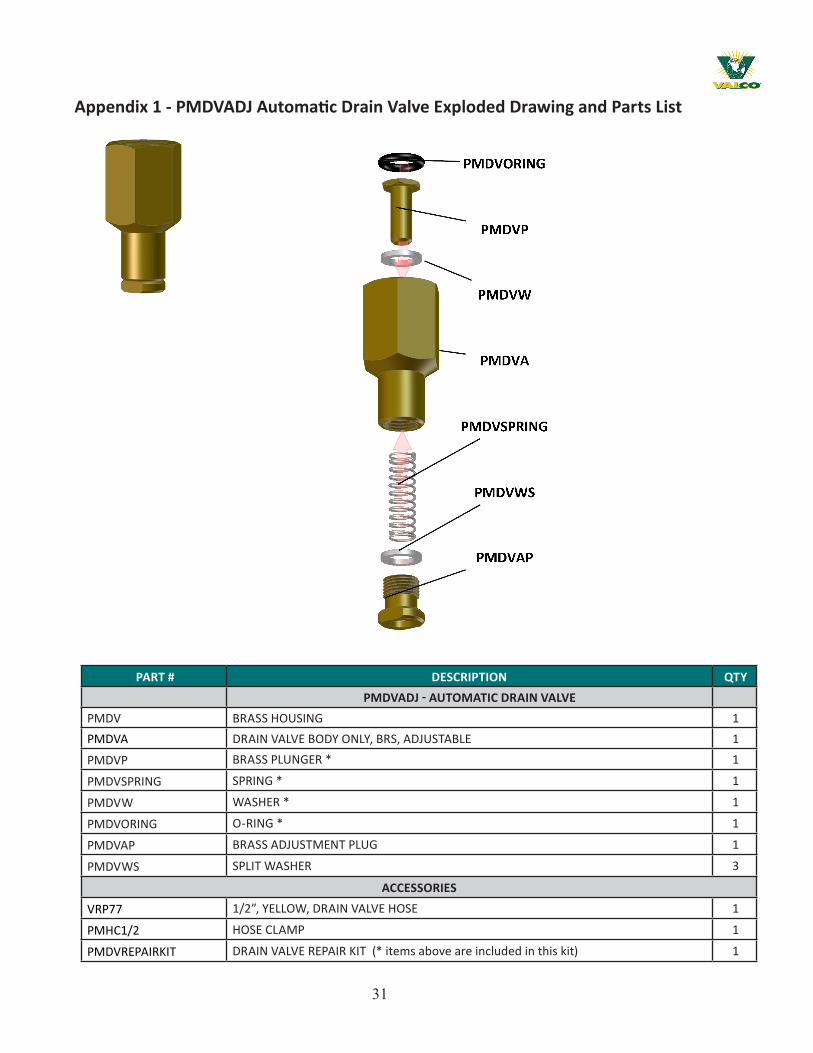
The PMDVADJ Automatic Drain Valve comes with three (3) optional PMDVWS Split Washers. The func-tion of the Split Washer (when added) is to reduce the travel distance of the PMDVP Plunger. This increases the time it takes for the Valve to close. If the Valve does not close while the system is being pressurized, up to THREE (3) OF THE split washers can be installed.
Note: Use only the number of Split Washers required for the Valve to close. Test after you add each Split Washer.
PMDVADJ Automatic Drain Valve

29
Drain Valve Line Assembly
NOZZLE LINE
8LM6-BR (1/2” COMP X 3/8” T THREAD)
PMDV (DRAIN VALVE ASSEMBLY)
HOSE CLAMP
1/2” RUBBER HOSE

30Intentionally Blank
31
Appendix 1 - PMDVADJ Automatic Drain Valve Exploded Drawing and Parts List
PART # DESCRIPTION QTYPMDVADJ - AUTOMATIC DRAIN VALVE
PMDV BRASS HOUSING 1PMDVA DRAIN VALVE BODY ONLY, BRS, ADJUSTABLE 1
PMDVP BRASS PLUNGER * 1
PMDVSPRING SPRING * 1
PMDVW WASHER * 1
PMDVORING O-RING * 1
PMDVAP BRASS ADJUSTMENT PLUG 1
PMDVWS SPLIT WASHER 3
ACCESSORIES
VRP77 1/2”, YELLOW, DRAIN VALVE HOSE 1
PMHC1/2 HOSE CLAMP 1
PMDVREPAIRKIT DRAIN VALVE REPAIR KIT (* items above are included in this kit) 1

32
Appendix 2 - Filter Kit Parts List
PART # DESCRIPTION QTY
FILTER CARTRIDGESPMCLR-5-10 5 MICRON FILTER CARTRIDGE, 10” 2-1/2” DIA 1PMCLR1-10 1 MICRON FILTER CARTRIDGE, 10” 2-1/2” DIA 1PM3P775 SCALE INHIBITOR FILTER CARTRIDGE, 10” 2-1/2” DIA 1
PMFILT5MBIGBLUE 5 MICRON BIG BLUE FILTER CARTRIDGE, 20” 4-1/2” DIA 1PMFILT1MBIGBLUE 1 MICRON BIG BLUE FILTER CARTRIDGE, 20” 4-1/2” DIA 1PMCLR-1-20 1 MICRON FILTER CARTRIDGE, 20” 2-1/2” DIA 1PMCLR-5-20 5 MICRON FILTER CARTRIDGE, 20” 2-1/2” DIA 1
VAL-CO® 10” YELLOW FILTER HOUSING:VF129 VAL FILTER HOUSING LID, 1” FNPT PORTS 1VF123 VAL FILTER HOUSING BOTTOM 1VF126 VAL FILTER HOUSING O-RING 1PMBIGBLUEWRENCH FILTER HOUSING WRENCH 1VF128 FILTER HOUSING MOUNTING BRACKET 1VRP05 HEX HD LAG SCREWS (used to attach Mounting Bracket to Filter Housing Lid) 1
PMSCH80850002 HEX HEAD PVC PLUG, 1/4” MNPT (used on Filter Housing Lid) 1PMSCH80850007 HEX HEAD PVC PLUG, 3/4” MNPT (used on Filter Housing Bottom) 1
STANDARD - 10” BLUE FILTER HOUSING:PM10FILTERHOUSE STANDARD FILTER HOUSING, 10”, 3/4” FNPT Ports 1PMFILTORING4 STANDARD FILTER HOUSING O-RING 1PMFILTERWRENCH STANDARD FILTER HOUSING WRENCH 1VF128-PM20 STANDARD FILTER HOUSING MOUNTING BRACKET 1VRP05 HEX HD SCREWS (used to attach Mounting Bracket to Filter Housing Lid) 1
STANDARD - 20” BLUE FILTER HOUSING: PM20FILTERHOUSE STANDARD FILTER HOUSING, 20”, 3/4” FNPT Ports 1PMFILTORING4 STANDARD FILTER HOUSING O-RING 1PMFILTERWRENCH STANDARD FILTER HOUSING WRENCH 1VF128-PM20 FILTER HOUSING MOUNTING BRACKET 1
VRP05 HEX HD SCREWS (used to attach Mounting Bracket to Filter Housing Lid) 1BIG BLUE 20” FILTER HOUSING:
PMFILT50GPM BIG BLUE FILTER HOUSING ASSEMBLY, 20”, 1”FNPT Ports 1
PMFILTORING6 BIG BLUE FILTER HOUSING O-RING 1
PMBIGBLUEWRENCH BIG BLUE FILTER HOUSING WRENCH 1
VF128 FILTER HOUSING MOUNTING BRACKET 1
PM5/16x1Lag HEX HD LAG SCREWS (used to attach Mounting Bracket to Filter Housing Lid) 1

33
Appendix 3 - 10-30 GPM Filter Kit Exploded drawing and Parts List
KEY PART NUMBER DESCRIPTION QTY10-30 GPM FILTER KIT
1 PM200PSIHOSE1 HOSE, 1” ID, BLUE, PVC 200 PSI W/VAL LAYLINE ON HOSE 20
2 PM5-16X1LAG 5/16” X 1” LAG SCREW 8
3 PMBIGBLUEWRENCH WRENCH FOR BIG BLUE HOUSING USE WITH # PMFILT50GPM 1
4 PMCKVALVE 3/4” PVC VALVE 1
5 PMFILT1MBIGBLUE 1 MICRON FILTER CARTRIDGE 4.5” O.D. X 20” LONG X 1” I.D. 1
6 PMFILT50GPM FILTER - 50 GPM 2
7 PMFILT5MBIGBLUE 5 MICRON FILTER CART 20”X4 1/2 FOR 40/50 GPM FILTER HOUSING 1
8 PMHC1-2 TRIDON HOSE CLAMP 3/8”- 7/8” 2
9 PMHC3-4 TRIDON HOSE CLAMP 3/4” 4
10 PMLPHOSE300PSI 1/2” ID HOSE 300PSI AT 70 DEG F BYPASS HOSE-KURI TEC YELL- 500’ 10
11 PMSCH803-4REDBUSHING 3/4” MNPT X 1/4” FNPT RED BUSHING SCH 80 2
12 PMSCH80350410 1” HOSE BARB X MNPT SCHEDULE 80 2
13 PMSCH80805010 1” FNPT X 1” FNPT X 1” FNPT TEE 3
14 PMSCH80839101 3/4” MNPT X 1/2” FNPT RED BUSHING 1
15 PMSCH80839131 1” MNPT X 3/4” FNPT REDUCING BUSHING 3
16 PMSCH80861104 3/4” X CLOSE NIPPLE, SCH 80 1
17 PMSCH80861134 1” x 2” CLOSE NIPPLE 4
18 VF128 FILTER BRACKET (ALUMINUM) 2
19 VG100 OIL FILLED PRESSURE GUAGE (0-100 PSI/BAR), 2 1/2” SS CASE 2
20 VRP71 1/2” THREADED MALE HOSE CONNECTOR (1/2” BARB) 1

34
Appendix 4 - Nozzle Exploded DrawingPMNOZ8 PM303NOZ8303SS

35
PART # DESCRIPTION QTY
NOZZLE LINE
PMNOZ8 NOZZLE / CHECK VALVE ASSEMBLY, 303 S/S (This assembly uses Copper Seals) 1
PMNOZ8FCFC NOZZLE ASSY W/CHECK VALVE 1
PM303NOZ8303SS NOZZLE ASSEMBLY, 303SS W/CHECK VALVE W/303SS SEALS 1
PM316NOZ8CG316SS NOZZLE ASSY, 316SS GROOVED W/CHECK VALVE AND 316SS SEALS 1
PMPLUG NOZZLE PLUG, 303 S/S (uses (1) PMNS-F Copper Seal) 1
PMPLUGX NOZZLE PLUG, 303 S/S (NO Seal included) 1
PMN8 NOZZLE BODY ONLY. 303 S/S 1
PMNCV CHECK VALVE BODY ONLY, 303 S/S 1
PMNS SEAL, FLAT - COPPER 1
PMNS303 SEAL, FLAT – 303 STAINLESS STEEL 1
PMNS-F SEAL, FLANGED - COPPER 1
PMNS-F303 SEAL, FLANGED – 303 STAINLESS STEEL 1
PMNPIN NOZZLE ATOMIZATION PIN, 303 S/S 1
PMCVSPRING CHECK VALVE SPRING, 316 S/S 1
PMCKVBALL CHECK VALVE BALL, 1/8” Dia, 70 DURO BUNA-NITRILE 1
PMNOZ8BRUSH NOZZLE CLEANING BRUSH 1PMVC-312-8 PM8 NOZZLE / CHECK VALVE PROTECTION CAP 1
Appendix 5 - Nozzle Assemblies and Spare Parts List

36
Appendix 6 - Accessory Parts List
PART # DESCRIPTION QTY
TUBING (* Sold by piece)
PMST1010 1” OD 316 GRADE SS Tube 10 ft length *
PMST1210 1/2” OD 316 GRADE SS TUBE 10 ft length *
PMST3410 3/4” OD 316 GRADE SS TUBE, .035” WALL 10 ft length *
PMST3420 3/4” OD 316 SS TUBE, .035” WALL, 20’ ft length *
PMST3810 3/8” OD 316 GRADE SS TUBE, .028” WALL, 10 ft length *
PMST3810M 3/8” OD 316 GRADE SS TUBE, .028” WALL, 4 METER PCS ONLY
PMST3820 3/8” OD 316 GRADE SS TUBE, .028” WALL, 20 Ft sections *
CABLE
PMCABL1000SS 1/16” STAINLESS STEEL CABLE, 1000 FT. ROLL 1
PMCABL500SS 1/16” STAINLESS STEEL CABLE, 500 FT ROLL 1
PMTIGHT 9” CABLE TIGHTNERS FOR STAINLESS STEEL CABLE 1
PMSLEEVE ALUMINUM CABLE SLEEVE FOR STAINLESS STEEL CABLE 1
TOOLS
VC300 CABLE CUTTER 3/16” MAX 1
PMPIPCUTTER SS PIPE CUTTER FOR HIGH PRESSURE MIST SYSTEM 1
PMSWAGETOOL 1/16” HAND SWAGE TOOL 1
1” TUBING3/8” TUBING 1/2” TUBING 3/4” TUBING

37
Appendix 7 - PolAIR® Control 400HC
Channel 1 - Inlet SolenoidChannel 2 - A1 Contactor Coil Channel 3 - Stage / Zone OneChannel 4 - Stage / Zone TwoChannel 5 - Drain Solenoid (State / Zone one)Channel 6 - Drain Solenoid (Stage / Zone Two)

38
Appendix 8 - PolAIR® EA-010-001 Control Drawing

39
PART # DESCRIPTION QTYVE-010-001 - POLAIR® 400HC CONTROL
EA-010-001 ENCL SUB ASSY CNTRL 4/6 HC 1CA-031-406 CABLE RBN ASSY 14P SKT-SKT 6.0 1EN-043-100 ENCL MACH POLAIR 1FS-017-022 FUSE FAST 6.3A 5X20MM 1
FS-15 FUSE SLO-BLO 1A 5MM X 20MM 1HW-100-008 #8 INTERNAL TOOTH WASHER 13HW-107-002 MTG PLATE MACH POLAIR R3 1HW-142-001 5/16-18X1 MACHINE PHD SS SCREW 1HW-143-001 5/16-18 NYLON NUT 1
HW-22 HEX NUT/#6-32 12HW-23 #6 INTERNAL TOOTH WASHER 12HW-38 5/8” STUD BROACH 6-32 UNF 8HW-46 #6 NYLON FLAT WASHER 12HW-53 SPACERS/#8-32X1/2” HEX 6HW-54 #8-32X.312 BROACHING STUD 6HW-55 #8-32x1/4” PH HD 6
PA-081-101 PCB ASSY CNTRL 4/6 HC 1PA-082-101 PCB ASSY RELAY 4/6 HC 1SW-026-002 SW TGL BOOT GY SILICONE 4
HW-22 HEX NUT/#6-32 2HW-23 #6 INTERNAL TOOTH WASHER 2
LD-117-001 DECAL POLAIR 400HC 1LD-117-003 DECAL MENU SET POLAIR 400HC 1
PM-063-003 MANUAL 1RY-010-004 CONTACTOR 3 POLE 23A 50/60 HZ 1RY-011-204 RELAY MTR OVERLOAD 5.4-27A 3 1
SW-026-002 SW TGL BOOT GY SILICONE 4WS-038-018 WIRE STRD UL1015 PVC 18AWG BLK 2.77
Appendix 9 - VE-010-001 POLAIR® 400 HC CONTROL PARTS LIST

40
PM
PV
& P
MP
HO
SE
AS
SE
MB
LY
PM
DV
AU
TO
MAT
IC D
RA
IN V
ALV
E
1/2
" P
MS
T1
21
0 M
AIN
LIN
E
10
00
-SE
RIE
S A
TO
MIZ
AT
ION
LIN
E
PR
ES
SU
RIZ
AT
ION
/FIL
TR
AT
ION
/CO
NT
RO
L M
OD
UL
E
LE
GE
ND
ELE
VAT
ION
10
00
-SE
RIE
S A
TO
MIZ
AT
ION
NO
ZZ
LE
LIN
E
PLA
N V
IEW
NO
VA
L C
ON
TR
OL
S
10
TS
WA
TE
R T
RE
AT
ME
NT S
YS
TE
M
FA
NS
AT
EA
CH
EN
D
(2)
PU
MP
SY
ST
EM
S(1
) 1
0T
S
J.
PA
RS
ON
S
1/1
0/9
9
NT
SC
ON
TA
CT:
LA
YE
R W
IN
T.
AT
OM
IZIN
G,
CO
OL
ING
, H
UM
IDIF
YIN
G S
YS
TE
MS
VA
L P
RO
DU
CT
S,
INC
.
P.O
. B
OX
95
8
LA
NC
AS
TE
R,
PA 1
76
03
TM
CU
ST
OM
ER
:
DW
G.
BY
:
DA
TE
:
SC
AL
E:
AP
VD
.:
DR
AW
ING
NO
.
SAMPLEDRAWINGFORREFERENCEONLY
Appendix 10 - Layout Option ExamplesSI
NG
LE S
TAG
E CO
OLI
NG
SYS
TEM
LAYE
R HO
USE
INTE
RNAL
NO
ZZLE
LIN
E

41
SIN
GLE
STA
GE
COO
LIN
G S
YSTE
MBR
OIL
ER H
OU
SE C
ROSS
FLO
W V
ENTI
LATI
ON
Appendix 10 - Layout Option Examples - continued
PM
PV
& P
MP
HO
SE
AS
SE
MB
LY
PM
DV
AU
TO
MAT
IC D
RA
IN V
ALV
E
PL
AN
VIE
W
PR
ES
SU
RIZ
AT
ION
/FIL
TR
AT
ION
/CO
NT
RO
L M
OD
ULE
LE
GE
ND 1/2
" P
MS
T1210 M
AIN
LIN
E
EX
HA
US
T F
AN
EL
EV
AT
ION
1000 S
ER
IES
AT
OM
IZA
TIO
N L
INE
1000 S
ER
IES
AT
OM
IZAT
ION
LIN
E
TE
MP
ER
AT
UR
E S
EN
SO
R
HU
MID
ITY
SE
NS
OR
J. P
AR
SO
NS
1/7
/00
NT
SC
ON
TA
CT:
AT
OM
IZIN
G, C
OO
LIN
G, H
UM
IDIF
YIN
G S
YS
TE
MS
VA
L P
RO
DU
CT
S, IN
C.
P.O
. B
OX
958 LA
NC
AS
TE
R, P
A 1
7603
TM
CU
ST
OM
ER
:
DW
G. B
Y:
DA
TE
:
SC
ALE
:
AP
VD
.:
DR
AW
ING
NO
.
T°
HT
°
T°
H
SAMPLEDRAWINGFORREFERENCEONLY

42
SIN
GLE
STA
GE
COO
LIN
G S
YSTE
MTU
NN
EL H
OU
SE
TM
CU
ST
OM
ER
:
DW
G. B
Y:
DA
TE
:
SC
ALE
:
AP
VD
.:
DR
AW
ING
NO
.
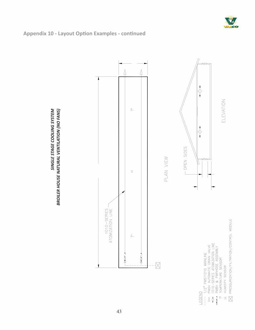
Appendix 10 - Layout Option Examples - continued
43
SIN
GLE
STA
GE
COO
LIN
G S
YSTE
MBR
OIL
ER H
OU
SE N
ATU
RAL
VEN
TILA
TIO
N (N
O F
ANS)
Appendix 10 - Layout Option Examples - continued
TM
CU
ST
OM
ER
:
DW
G.
BY
:
DA
TE
:
SC
AL
E:
AP
VD
.:
DR
AW
ING
NO
.

44
TM
CU
ST
OM
ER
:
DW
G. B
Y:
DA
TE
:
SC
ALE
:
AP
VD
.:
DR
AW
ING
NO
.
SIN
GLE
STA
GE
RAIN
BOW
CO
OLI
NG
(40
’ X 3
00’)
NAT
URA
L VE
NTI
LATI
ON
W/C
IRCU
LATI
ON
FAN
S
Appendix 10 - Layout Option Examples - continued

45
Appendix 10 - Layout Option Examples - continued
TM
CU
ST
OM
ER
:
DW
G.
BY
:
DA
TE
:
SC
AL
E:
AP
VD
.:
DR
AW
ING
NO
.
SIN
GLE
STA
GE
RAIN
BOW
CO
OLI
NG
(40
’ X 3
50’)
NAT
URA
L VE
NTI
LATI
ON
W/C
IRCU
LATI
ON
FAN
S

46
Appendix 10 - Layout Option Examples - continued
TM
CU
ST
OM
ER
:
DW
G. B
Y:
DA
TE
:
SC
ALE
:
AP
VD
.:
DR
AW
ING
NO
.
SIN
GLE
STA
GE
RAIN
BOW
CO
OLI
NG
(40
’ X 4
00’)
NAT
URA
L VE
NTI
LATI
ON
W/C
IRCU
LATI
ON
FAN
S

47
Appendix 10 - Layout Option Examples - continued
SIN
GLE
STA
GE
RAIN
BOW
CO
OLI
NG
(40
’ X 5
00’)
NAT
URA
L VE
NTI
LATI
ON
W/C
IRCU
LATI
ON
FAN
S
TM
CU
ST
OM
ER
:
DW
G.
BY
:
DA
TE
:
SC
AL
E:
AP
VD
.:
DR
AW
ING
NO
.

48
PM
DV
AU
TO
MAT
IC D
RA
IN V
ALV
E
PR
ES
SU
RIZ
AT
ION
/FIL
TR
AT
ION
/CO
NT
RO
L M
OD
ULE
1000-S
ER
IES
AT
OM
IZAT
ION
LIN
E
PM
PV
& P
MP
HO
SE
AS
SE
MB
LY
EL
EV
AT
ION
10T
S W
AT
ER
TR
EA
TM
EN
T S
YS
TE
M
EX
HA
US
T F
AN
1/2
" P
MS
T1210 M
AIN
LIN
E
LE
GE
ND
PL
AN
VIE
W
NO
SE
NS
OR
S,
SY
ST
EM
WIL
L O
PE
RAT
E F
RO
M C
US
TO
ME
R C
OM
PU
TE
R
10
00
-SE
RIE
S A
TO
MIZ
AT
ION
NO
ZZ
LE
LIN
E
SAMPLEDRAWINGFORREFERENCEONLY
ST
AG
E O
NE
ST
AG
E O
NE
ST
AG
E T
WO
ST
AG
E T
WO
J.
PA
RS
ON
S
1/1
0/9
9
NT
S
CO
NT
AC
T:
AT
OM
IZIN
G,
CO
OL
ING
, H
UM
IDIF
YIN
G S
YS
TE
MS
VA
L P
RO
DU
CT
S,
INC
.
P.O
. B
OX
95
8
LA
NC
AS
TE
R,
PA 1
76
03
TM
CU
ST
OM
ER
:
DW
G.
BY
:
DA
TE
:
SC
AL
E:
AP
VD
.:
TWO
STA
GE
COO
LIN
G S
YSTE
MLA
YER
HOU
SE W
/CO
OLI
NG
CO
RRID
OR
Appendix 10 - Layout Option Examples - continued

49
Appendix 11 - Fog System Design Request Sheet
POLAIR HIGH PRESSURE FOG SYSTEM POULTRY - DESIGN REQUEST SHEETVAL-CO Salesman NameVAL-CO Distributor Company
ContactPhoneFaxE-Mail
End User CompanyContactPhoneFaxE-Mail
Structure Location CityStateCountry
BASIC STRUCTURE INFORMATIONLengthWidthSide Wall HeightPeak Height
Closed CeilingCeiling Height from floor
Open CeilingInsulated CeilingDistance between Cross TrussesCross Truss height from floor
UTILITIES INFORMATIONElectric Water SupplyHertz 50 City
60 WellAvailable Three (3) Phase Power Available Single (1) Phase Power Pond
200 415 100 200 Brackish208 440 110 208 RO220 460 115 220 Other230 480 120 230240 575 127 240 Water Pressure380 600 Other PSI400 Other kPa
Three (3) Phase NOT Available Bar
50
Appendix 11 - Fog System Design Request Sheet - continued
VENTILATION INFORMATIONNatural Ventilation Mechanical Ventilation
Ridge Vent Total Number of Exhaust FansSide Wall Curtain TOTAL Combined CFM of Exhaust Fans
HeightLength Tunnel VentilatedRaises to open Side Wall ConstructionLowers to open Solid
CurtainStir Fans Air Inlets Quantity
Size Height of eachQuantity Length of each
TOTAL Combined CFMCross Ventilated
Air Inlets QuantityHeight of eachLength of each
High Rise Lay HouseExterior Cooling Corridor/Chamber
HeightWidthLengthQuantity
TYPE OF PRODUCTIONLAYER BROILER TURKEY Pullets
Breeders
Caged Number of BirdsCage Free
Number of Birds
White or Brown White or BrownCage Length Nest Length# of Cage Rows # of Rows# of Cage Tiers ConventionalCage Type A - Frame Community Side Belt
Stacked Community Center Belt
* Distance between the TOP of the Cage and the Ceiling or Cross Truss Use additional page (if needed) to best show in detail with measurements: * An over view of the structure.* A cross section of the structure.* The desired location of the PolAir Fog System Pump Unit/s.* Air inlets locations.

51
Appendix 12 - Customer Service
My dealer’s name:
_____________________________________________________
How to contact my dealer:
Customer Service210 E. Main Street P. O. Box 117 Coldwater, OH 45828800.998.2526
Street / PO Box ______________________________
City ______________________________
State / Province ______________________________
Zip / Postal ______________________________
Phone ______________________________
Fax ______________________________
E-mail ______________________________
Web site ______________________________
North America: Phone: 800.99VALCO (800.998.2526)Fax: 419.678.2200Email: [email protected]
International:Phone: (+1) 419.678-88731Fax: 419.678.2200Email: [email protected]


![RocksDB and MongoRocks - Percona · PDF filefile format (data block) aaaaaaa : val aaaaaab : val aaaaaac : val aabaaaa : val aabaaax : val aaaaaaa : val [6]b : val [6]c : val [2]baaaa](https://static.fdocuments.in/doc/165x107/5a78a2407f8b9a87198e3d9a/rocksdb-and-mongorocks-percona-format-data-block-aaaaaaa-val-aaaaaab-val.jpg)