Intention Driven Modeling for Flexible Workflow...
14
Intention Driven Modeling for Flexible Workflow Applications Selmin Nurcan 1 , 2 , Marc-Henri Edme 1 1 Université Paris 1 - Panthéon - Sorbonne Centre de Recherche en Informatique 90, rue de Tolbiac 75634 Paris cedex 13 France 2 IAE de Paris (Graduate Business School of Sorbonne) Université Paris 1 - Panthéon - Sorbonne 21, rue Broca 75005 Paris France [email protected], [email protected] Abstract. Traditional information system development approaches led to the construction of application islands. During the early 90’s, workflow technologies were the only ones to offer a transversal integration capacity to the enterprise applications. However, the formalisms developed for workflow specifications were almost systematically activity oriented. Consequently, the resulting process definitions have the advantage to be easily transformable in executable code but the disadvantage of being prescriptive and rigid. Recent works underline the needs in term of flexible and adaptive workflows, whose execution can evolve according to situations that cannot always be prescribed. This paper proposes a conceptual framework for an intention driven modeling of flexible workflow applications. The purpose of the underlying modeling formalism is to define an integration/orchestration for islands of business process chunks. The modeling framework offers the ability to represent in the same business process definition the well-structured process chunks as well as the ill-structured or ad hoc ones. 1. Introduction In evolving environments, the capacity of quick reaction of organizations is mainly due to the ability of handling the support systems in favor of the business evolution requirements. In all management challenges, information systems (IS) should be continuously adapted to changing business practices and needs. This can be achieved by developing process-centric solutions. In fact, the paradigm of Business Process Management stresses the importance of integrating entire processes rather than simply integrating data or applications [8], [39]. Workflow Management Systems (WFMS) have often been positioned as an appropriate technological solution for integrating process islands at a high level so that they can collaboratively provide business solutions that each individual application is unable to provide. However commercial WFMS offer only limited evolution facilities. Enterprise modeling refers to a collection of conceptual modeling techniques for describing multiple facets of an enterprise including operational (information systems), organizational (business processes, actors, roles, flow of information etc), and teleological (purposes) considerations [5], [30], [33], [37]. Our experience on Business Process Modeling, Business Process Reengineering and IS engineering led us to the following findings: 1. The amount of detail to be handled in analyzing and improving business processes makes it difficult to master. Approaches and models offering the ability to describe, initially, the invariants of the organization in terms of objectives and strategies before specifying the manner of making them operational, facilitate to mastering these difficulties. 2. Using models to represent the enterprise permits (i) to provide a more coherent and complete description of the business than a textual description, (ii) to reason on alternative solutions and diverging points of view, and (iii) to reach an agreement. 3. A clear representation of the business objectives simplifies the comprehension of the organizational change and the evolution of the business model. 4. The importance of establishing and preserving the ‘best fit’ between organization needs (whys) and system functionalities (how), i.e. between process models and IS specifications is commonly accepted. In this paper, we propose to use the Map Model, for modeling flexible workflow applications. The Map approach provides a representation system based on intentions and strategies. Intentions abstract from organizational tasks and the different ways in which tasks are performed are intention achievement strategies. The purpose to measure the capacity of the Map Model, and more generally of the objective oriented formalisms, to represent business processes of various natures and to support their evolution. 1
Transcript of Intention Driven Modeling for Flexible Workflow...
Intention Driven Modeling for Flexible Workflow Applications
Selmin Nurcan1, 2, Marc-Henri Edme 1
1 Université Paris 1 - Panthéon - Sorbonne
Centre de Recherche en Informatique 90, rue de Tolbiac 75634 Paris cedex 13 France
2 IAE de Paris (Graduate Business School of Sorbonne) Université Paris 1 - Panthéon - Sorbonne
21, rue Broca 75005 Paris France
[email protected], [email protected]
Abstract. Traditional information system development approaches led to the construction of application islands. During the early 90’s, workflow technologies were the only ones to offer a transversal integration capacity to the enterprise applications. However, the formalisms developed for workflow specifications were almost systematically activity oriented. Consequently, the resulting process definitions have the advantage to be easily transformable in executable code but the disadvantage of being prescriptive and rigid. Recent works underline the needs in term of flexible and adaptive workflows, whose execution can evolve according to situations that cannot always be prescribed. This paper proposes a conceptual framework for an intention driven modeling of flexible workflow applications. The purpose of the underlying modeling formalism is to define an integration/orchestration for islands of business process chunks. The modeling framework offers the ability to represent in the same business process definition the well-structured process chunks as well as the ill-structured or ad hoc ones.
1. Introduction
In evolving environments, the capacity of quick reaction of organizations is mainly due to the ability of handling the support systems in favor of the business evolution requirements. In all management challenges, information systems (IS) should be continuously adapted to changing business practices and needs. This can be achieved by developing process-centric solutions. In fact, the paradigm of Business Process Management stresses the importance of integrating entire processes rather than simply integrating data or applications [8], [39]. Workflow Management Systems (WFMS) have often been positioned as an appropriate technological solution for integrating process islands at a high level so that they can collaboratively provide business solutions that each individual application is unable to provide. However commercial WFMS offer only limited evolution facilities.
Enterprise modeling refers to a collection of conceptual modeling techniques for describing multiple facets of an enterprise including operational (information systems), organizational (business processes, actors, roles, flow of information etc), and teleological (purposes) considerations [5], [30], [33], [37].
Our experience on Business Process Modeling, Business Process Reengineering and IS engineering led us to the following findings: 1. The amount of detail to be handled in analyzing and improving business processes makes it difficult to
master. Approaches and models offering the ability to describe, initially, the invariants of the organization in terms of objectives and strategies before specifying the manner of making them operational, facilitate to mastering these difficulties.
2. Using models to represent the enterprise permits (i) to provide a more coherent and complete description of the business than a textual description, (ii) to reason on alternative solutions and diverging points of view, and (iii) to reach an agreement.
3. A clear representation of the business objectives simplifies the comprehension of the organizational change and the evolution of the business model.
4. The importance of establishing and preserving the ‘best fit’ between organization needs (whys) and system functionalities (how), i.e. between process models and IS specifications is commonly accepted.
In this paper, we propose to use the Map Model, for modeling flexible workflow applications. The Map approach provides a representation system based on intentions and strategies. Intentions abstract from organizational tasks and the different ways in which tasks are performed are intention achievement strategies. The purpose to measure the capacity of the Map Model, and more generally of the objective oriented formalisms, to represent business processes of various natures and to support their evolution.
1

The paper is organized as follows: Section 2 presents a survey on business processes (BPs) modeling solutions and discusses some limits of the current WFMS. Section 3 proposes an intention driven modeling framework for the representation of flexible business processes. Section 4 presents the software support developed for the execution of those business process models. Section 5 discusses the related work.
2. A survey on business process modeling formalisms and on workflow technologies as support systems
BPs can be roughly classified into two categories: (i) well-defined and -often- repetitive processes having important coordination and automation needs; (ii) ill-defined processes requiring information and knowledge sharing between the involved actors.
2.1. Business process modelling formalisms
BP modeling usually combines three views: (i) the functional view is expressed using Data Flow Diagrams [22]; (ii) the behavioral view focuses on when and under which conditions activities are performed; this view is described using state diagrams or interaction diagrams [16]; and (iii) the structural view focuses on static aspects capturing the objects that are manipulated in BPs [34].
Existing process modeling formalisms can be classified into three categories: activity-oriented, product-oriented and decision-oriented ones.
Activity-oriented formalisms allow us to prescribe a process as a set of activities to be performed and their relationships regarding control and data flows which are pre-defined [16], [14], [22]. This kind of models is useful for representing the functional view of BPs. Nevertheless, the linear view of activity decomposition is inadequate for modeling, and consequently for guiding, ill-defined BPs, particularly if the latter suffer frequent changes and/or alternative choices are based on human decisions instead of calculable arguments.
Product-oriented formalisms do not put forward the activities of a process but rather the result of these activities. A positive aspect is that they model the evolution of the product and couple the product state to the activities that generate this state [34]. State diagrams are used to design complex event-driven processes which continuously interact on environment stimuli [16]. These are used for representing the structural and behavioral views introduced below. These models are more appropriate than activity-oriented ones for representing ill-defined BPs. However as far as guidance is concerned, and considering the highly non-deterministic nature of ill-defined processes, it seems difficult to write down a realistic state-transition diagram that adequately describes what has to happen.
The most recent type of process models [17], [32], [31] is based on the decision-oriented paradigm according to which the successive transformations of the product are looked upon as consequences of decisions. Users are considered being ‘knowledgeable’ on BPs which can not be entirely pre-defined using control flows among activities [11], [13]. Such models are semantically more powerful than the two others because they explain not only how the process proceeds but also why. Their enactment guide the decision making process that shapes the business, help reasoning about the rationale. They are particularly appropriate for representing BPs requiring flexibility [27].
More recent BP modeling languages provide concepts for activity-oriented and product-oriented representations of BPs. None of them support the decision oriented paradigm. The Unified Modeling Language (UML) allows modeling not only application structures, behaviors and architectures, but also BPs [38]. Event-Driven Process Chains (EPC) have been introduced by Keller, Nüttgens and Scheer as a modeling concept to represent temporal and logical dependencies between functions, events or connectors which are linked via control flows. An interchange format for EPCs, EPC Markup Language (EPML), has been proposed in [23]. The Business Process Management Initiative (BPMI) developed open specifications to enable the standards-based management of cross-enterprise processes based on BPM Systems [6]. The Business Process Modeling Language (BPML) defines a formal model for expressing abstract and executable processes that address all aspects of BPs, including activities of varying complexity, transactions and their compensation, data management, concurrency and exception handling. The Business Process Modeling Notation (BPMN) [7] defines a BP model as a network of activities and the flow controls that define their order of performance. Its essential goal is to provide a notation that is understandable by all business users, from the business analysts to the developers, and finally to the business actors.
2

2.2. Workflow technologies for defining and enacting business processes
According to [41], a process definition consists of a network of activities and their relationships, criteria to indicate the start and termination of the process, and information about the individual activities such as participants, associated IT applications supporting them and data, etc. This definition corresponds to a prescriptive process model in the sense that "how things must/should/could be done" should be pre-defined before the enactment of the process definition. Remind that, in opposite, a descriptive process model aims at recording and providing a trace of what happens during the BP [15].
The commonly used classification for workflow applications divides them into four classes [2]: (i) Production workflows involve repetitive and predictable BPs. They implement the core processes of the
enterprise and incorporate access to various ISs. Production workflows are the closest category to the existing commercial WFMS solutions and to the generic workflow product structure adopted by WfMC [41];
(ii) Administrative workflows involve repetitive, predictable BPs with simple task coordination rules and do not concern the core processes of the enterprise;
(iii) Ad hoc workflows have no predefined structure. They tend to be created to deal with exceptions or where there is no set pattern for moving information among people. The coordination of the activities is controlled by human participants;
(iv) Collaborative workflows include iterative tasks over the same step until some form of agreement has been made. It seems very difficult to model those using classical WFMSs and the underlying activity-oriented (prescriptive) models since it is impossible to predefine the steps to follow. Most of the co-ordination is done by human participants.
In terms of automated support for executing BP models, most of the existing commercial WFMS and the underlying control flow models are useful for well-defined and repetitive BPs (production and administrative). They cannot be used for ill-defined BPs (ad hoc and collaborative) neither to deal with the dynamic modification of well-defined ones. In evolving environments, business actors need flexible models to define their BPs and for adaptive WFMS to control their execution. Few WFMSs (InConcert, Ensemble and TeamWARE flow) allow creating and modifying process definitions during their execution. For instance, Inconcert supports the definition of workflow models by discovering, i.e. by induction from process instances [40].
The state of the art allows us to distinguish principally two kind of flexibility depending if the capacity of dealing with change might be incorporated in the process definitions during build-time or run-time.
Flexibility a posteriori or by adaptation allows to adapt the process definition or some of its instances during their execution. This is the most usual case found in the literature [9], [10], [18], [24], [36], [42]. Approaches which offer only this kind of flexibility are based on prescriptive modeling formalisms. It could be considered that the resulting process definitions are not really flexible but rather adaptive or evolutionary. In fact, these approaches can not anticipate the capacity to change during the build-time. Prescriptive modeling formalisms are well adapted to specify BPs which require high degree of control and prediction and for which the need for change remains an exception, i.e. production workflows [20].
Flexibility a priori or by selection is based on modeling formalisms which can offer the capacity to deal with the environmental change without any evolution of process definitions. This means that this capacity should be incorporated in process definitions during build-time. The process definition should be specified in a sufficiently flexible way so that it will yield under the influence of the environment without breaking. Accordingly, the workflow enactment service should be able to execute ‘incomplete’ specifications of process definitions. Therefore the enactment service depends on user decisions for selecting a process component (dynamic construction of the process instance) [21]; executing a path among several possible; selecting a behavior to associate to a process component (actor, activity, resource,...) or selecting a way-of-doing to perform an activity [13].
These two techniques are not mutually exclusive [1], [11], [13], [32]. It is recommended to offer the possibility of adapting a process instance when a not anticipated event happens and the system can not deal with it using its ‘a priori’ flexibility capacities.
The purpose of the work presented in the following section is to provide a solution to integrate the flexibility in the process definitions during the built-time. It concerns the flexibility by selection, even if the proposed representation system allows also supporting the flexibility by adaptation.
3
3. An intention driven modeling framework for flexible representation of business processes
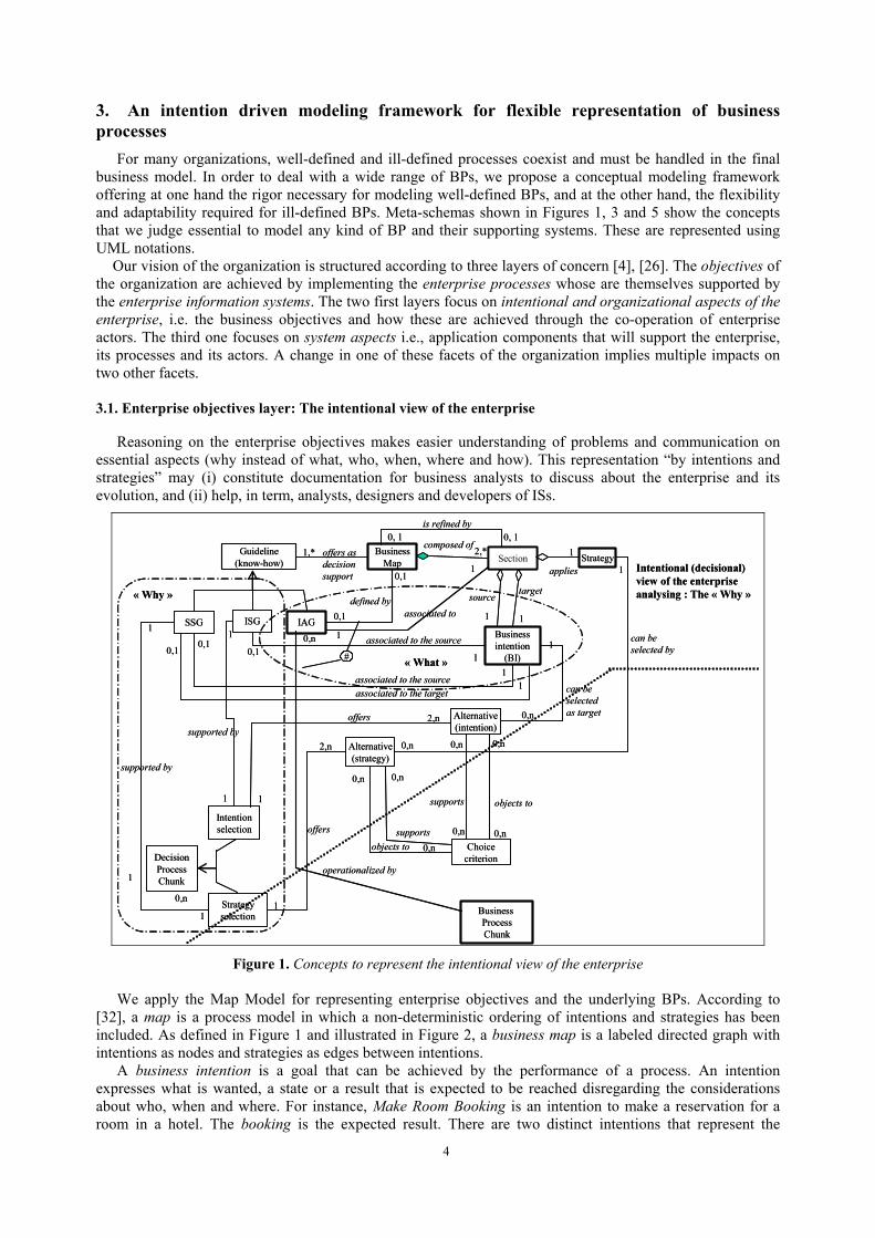
For many organizations, well-defined and ill-defined processes coexist and must be handled in the final business model. In order to deal with a wide range of BPs, we propose a conceptual modeling framework offering at one hand the rigor necessary for modeling well-defined BPs, and at the other hand, the flexibility and adaptability required for ill-defined BPs. Meta-schemas shown in Figures 1, 3 and 5 show the concepts that we judge essential to model any kind of BP and their supporting systems. These are represented using UML notations.
Our vision of the organization is structured according to three layers of concern [4], [26]. The objectives of the organization are achieved by implementing the enterprise processes whose are themselves supported by the enterprise information systems. The two first layers focus on intentional and organizational aspects of the enterprise, i.e. the business objectives and how these are achieved through the co-operation of enterprise actors. The third one focuses on system aspects i.e., application components that will support the enterprise, its processes and its actors. A change in one of these facets of the organization implies multiple impacts on two other facets.
3.1. Enterprise objectives layer: The intentional view of the enterprise
Reasoning on the enterprise objectives makes easier understanding of problems and communication on essential aspects (why instead of what, who, when, where and how). This representation “by intentions and strategies” may (i) constitute documentation for business analysts to discuss about the enterprise and its evolution, and (ii) help, in term, analysts, designers and developers of ISs.
BusinessMap Section
composed of2,*
Business intention
(BI)
sourcetarget
1 1
Strategy1
applies
Guideline (know-how)
offers as decisionsupport
1,*
SSG ISG IAG
associated to the source
10,1
Intentionselection
1
1
supported byoffers 2,n Alternative
(intention)
1
0,n
1
Choicecriterion
supports objects to
0,n
0,n
0,n
0,n
Strategyselection
supported by
1
Alternative(strategy)
offers
2,n
1
can beselectedas target
0,n
1
can beselected by
0,n 0,n
0,nsupports
objects to
associated to the source1
associated to the target1
0,10,1
Business ProcessChunk
0,n
operationalized by
0,n
Intentional (decisional)view of the enterpriseanalysing : The « Why »
1
1
0,1defined by
0,1
#
associated to
1
1
DecisionProcessChunk
« Why »
« What »
is refined by0, 10, 1
Figure 1. Concepts to represent the intentional view of the enterprise
We apply the Map Model for representing enterprise objectives and the underlying BPs. According to [32], a map is a process model in which a non-deterministic ordering of intentions and strategies has been included. As defined in Figure 1 and illustrated in Figure 2, a business map is a labeled directed graph with intentions as nodes and strategies as edges between intentions.
A business intention is a goal that can be achieved by the performance of a process. An intention expresses what is wanted, a state or a result that is expected to be reached disregarding the considerations about who, when and where. For instance, Make Room Booking is an intention to make a reservation for a room in a hotel. The booking is the expected result. There are two distinct intentions that represent the
4
intentions to start navigating in the map and to stop doing so. A strategy is an approach, a manner to achieve an intention. Let us suppose that bookings can be made on
the Internet. This is a way of achieving the room booking intention, i.e. a strategy. By visiting a travel agency is another strategy to achieve the same intention. A business map consists of a number of sections each of which is a triplet < source intention Ii, target intention Ij, strategy Sij>. The strategy characterizes the flow from Ii to Ij and the way Ij can be achieved. The business map contains a finite number of paths from Start to Stop, each of them prescribing a way to develop the product (for instance a service to be delivered for a customer), i.e. each of them is a Business Process Model. Thus the map is a multi-model. The approach suggests a dynamic construction of the actual path by navigating in the map.
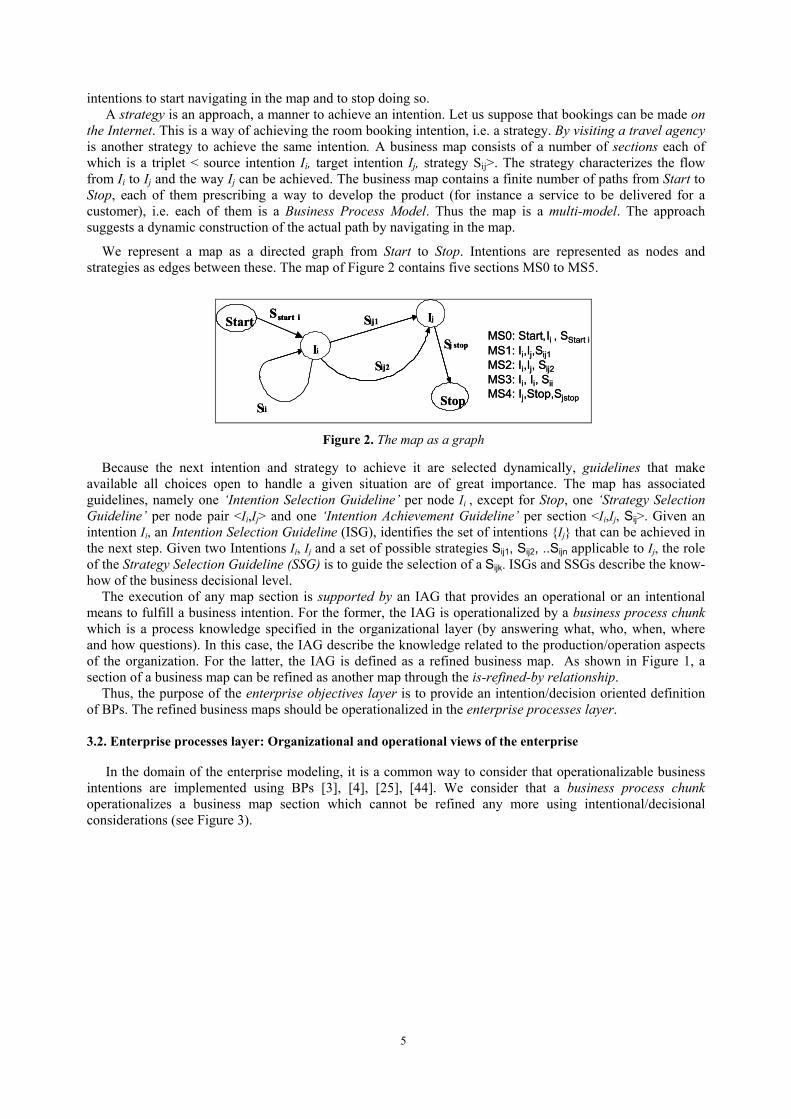
We represent a map as a directed graph from Start to Stop. Intentions are represented as nodes and strategies as edges between these. The map of Figure 2 contains five sections MS0 to MS5.
Sii
Sij1
Sij2
MS0: Start Ii , SStart i,MS1: Ii,Ij,Sij1MS2: Ii,Ij, Sij2MS3: Ii, Ii, SiiMS4: Ij,Stop,Sjstop
Ij
Ii
Start
Stop
Sstart i
Sj stop
Sii
Sij1
Sij2
MS0: Start Ii , SStart i,MS1: Ii,Ij,Sij1MS2: Ii,Ij, Sij2MS3: Ii, Ii, SiiMS4: Ij,Stop,Sjstop
Ij
Ii
Start
Stop
Sstart iSstart i
Sj stop
Figure 2. The map as a graph
Because the next intention and strategy to achieve it are selected dynamically, guidelines that make available all choices open to handle a given situation are of great importance. The map has associated guidelines, namely one ‘Intention Selection Guideline’ per node Ii , except for Stop, one ‘Strategy Selection Guideline’ per node pair <Ii,Ij> and one ‘Intention Achievement Guideline’ per section <Ii,Ij, Sij>. Given an intention Ii, an Intention Selection Guideline (ISG), identifies the set of intentions {Ij} that can be achieved in the next step. Given two Intentions Ii, Ij and a set of possible strategies Sij1, Sij2, ..Sijn applicable to Ij, the role of the Strategy Selection Guideline (SSG) is to guide the selection of a Sijk. ISGs and SSGs describe the know-how of the business decisional level.
The execution of any map section is supported by an IAG that provides an operational or an intentional means to fulfill a business intention. For the former, the IAG is operationalized by a business process chunk which is a process knowledge specified in the organizational layer (by answering what, who, when, where and how questions). In this case, the IAG describe the knowledge related to the production/operation aspects of the organization. For the latter, the IAG is defined as a refined business map. As shown in Figure 1, a section of a business map can be refined as another map through the is-refined-by relationship.
Thus, the purpose of the enterprise objectives layer is to provide an intention/decision oriented definition of BPs. The refined business maps should be operationalized in the enterprise processes layer.
3.2. Enterprise processes layer: Organizational and operational views of the enterprise
In the domain of the enterprise modeling, it is a common way to consider that operationalizable business intentions are implemented using BPs [3], [4], [25], [44]. We consider that a business process chunk operationalizes a business map section which cannot be refined any more using intentional/decisional considerations (see Figure 3).
5
IAG
Choicecriterion based on the state of
0,n 1,n
Business ProcessChunk
CompoundBPC Activity
Ill-structuredBPC
Groupe Activity
(unstructured)
Individualactivity
Precedencelink
precedencegraph
2,n
1
from
to0,n0,n 0,1
0,1
bag of
0,n
allowed if
0,n
0,n
Role
1
supports thedecision of
0,n
IndividualGroup
performed by 0,n
1
1
0,nincludes2,n0,n
Businessobjects
1,*
usesproduces
0,n0,n
0,n 0,n
Event
generates1,n 1,n
2,n
1,1triggered by
Actorheld by1,n 1,n
0,n
operationalized by
0,1
performed by
handles1,n
1,n
1
DecisionProcessChunk
1,n
0,n
performed by
Organisational & operationalview of the enterpriseanalysing : The « what, who, when, where & how »
1,1
1,n
Action
defined as
1,n
1,1
0,n 1,n
0,n
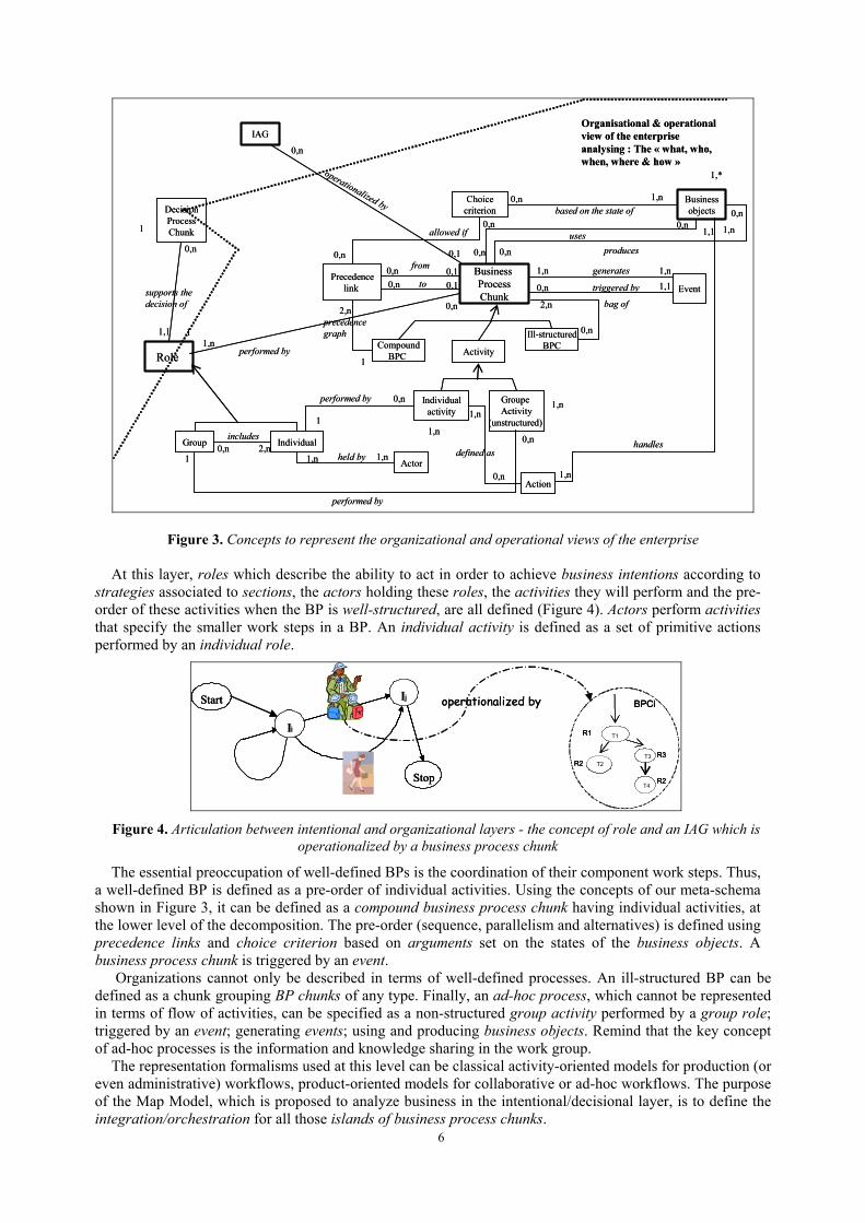
Figure 3. Concepts to represent the organizational and operational views of the enterprise
At this layer, roles which describe the ability to act in order to achieve business intentions according to strategies associated to sections, the actors holding these roles, the activities they will perform and the pre-order of these activities when the BP is well-structured, are all defined (Figure 4). Actors perform activities that specify the smaller work steps in a BP. An individual activity is defined as a set of primitive actions performed by an individual role.
Ij
Ii
Start
Stop
R1
BPCi
T1
T2R2 R3
R2
T3
T4
operationalized byIj
Ii
Start
Stop
Ij
Ii
Start
Stop
R1
BPCi
T1
T2R2 R3
R2
T3
T4
R1
BPCi
T1
T2R2 R3
R2
T3
T4
operationalized by
Figure 4. Articulation between intentional and organizational layers - the concept of role and an IAG which is
operationalized by a business process chunk
The essential preoccupation of well-defined BPs is the coordination of their component work steps. Thus, a well-defined BP is defined as a pre-order of individual activities. Using the concepts of our meta-schema shown in Figure 3, it can be defined as a compound business process chunk having individual activities, at the lower level of the decomposition. The pre-order (sequence, parallelism and alternatives) is defined using precedence links and choice criterion based on arguments set on the states of the business objects. A business process chunk is triggered by an event.
Organizations cannot only be described in terms of well-defined processes. An ill-structured BP can be defined as a chunk grouping BP chunks of any type. Finally, an ad-hoc process, which cannot be represented in terms of flow of activities, can be specified as a non-structured group activity performed by a group role; triggered by an event; generating events; using and producing business objects. Remind that the key concept of ad-hoc processes is the information and knowledge sharing in the work group.
The representation formalisms used at this level can be classical activity-oriented models for production (or even administrative) workflows, product-oriented models for collaborative or ad-hoc workflows. The purpose of the Map Model, which is proposed to analyze business in the intentional/decisional layer, is to define the integration/orchestration for all those islands of business process chunks.
6

3.3. Information systems layer: IT support view of the enterprise
The focus of the bottom level of the conceptual framework is the IT system that has to support the enterprise processes in order to achieve the enterprise objectives. An individual software component supports an individual activity and a group component supports a group activity, if these activities can be computerized.
Individual software components are specified thanks to the actions that compose the activity. Each action handles a given business object. This corresponds to traditional transactional activities, which perform well-identified operations on databases. For all other kind of individual activities, the relationship defined as does not apply.
Business ProcessChunk
Activity
Groupe Activity
(unstructured)
Individualactivity
Role
1
supports thedecision of
0,n
0,n
0,n
Businessobjects
Event
generates1,n 1,n1,1triggered by0,n
IT component
Individualcomponent
Groupcomponent
0,1
0,1guided by
IT support viewof the enterprise: The « how »
authorized to use 0,n
1,n
supported by
supported by
0,1
1,n
1,n
1
DecisionProcessChunk Organisational & operational
view of the enterprise
1,1
Repository
implem
ents
1,n
0,nAction
defined as
1,n
1,1
1,n
0,n 1,n
Figure 5. Concepts to represent the IT support view
3.4. Example
We wish to model the loan handling process in a bank. When a customer applies for a loan, the clerk in charge of his account sets up a file with the data corresponding to the request (loan amount, rate, account situation...). When the request is registered, it could be evaluated, either by the loan service clerk himself, or by the financial department and then the loan manager, in order to accept or to refuse the loan request. In the second case, a group of experts in the financial department performs a financial evaluation, and the loan manager in the light of their suggestions examines the request. In the first case, the loan manager should validate the evaluation performed by the loan service clerk. He has the possibility either to accept the loan offer, to ask the loan service clerk to review it, or to ask a complete re-evaluation to the financial department. When the decision is favorable, the clerk’s assistant sends a proposal of loan stipulating the amount, the duration and the refunding modalities of the loan to the customer; when the decision is unfavorable, he sends a refusal letter. The customer has to sign the contract in the authorized time, otherwise the offer is cancelled.
The global business map, shown in Figure 6 includes two high-level business intentions and nine strategies.
7
Global Business Map
Refined Business Maps
material
Start
Agent contactstrategy
Handlethe loan
C3
Handle theloan request
Direct bankstrategy C2
fixed rate strategy
revisable rate strategy
flexible coverings withfixed term strategy
C4 C5
contractrenegotiation strategy
Stopby normal cloture of the loan
C6C7
C8
by dispute
by notification ofcloture of the offerC9
The business map: Manage loans
C1
C1.1
material
partial
Without
Stop
Monitorstock
Start
loanrequest
By
filteringfiltering
Stop
Financial evalutionstrategy
I2: Make theloan offer
Delegationstrategy
Riskstrategy
Offer limitedin timestrategy
Requirement on theof the customer strategy
C1.2
C1.3
C1.4C1.5
C1.6 C1.7
The refined map: C1: <Start, Handle the loan request, Agent contact strategy>
ISG1
SSG1
I1: Register
material
Start
Agent contactstrategy
Handlethe loan
C3
Handle theloan request
Direct bankstrategy C2
fixed rate strategy
revisable rate strategy
flexible coverings withfixed term strategy
C4 C5
contractrenegotiation strategy
Stopby normal cloture of the loan
C6C7
C8
by dispute
by notification ofcloture of the offerC9
The business map: Manage loans
C1
C1.1
material
partial
Without
Stop
Monitorstock
Start
loanrequest
By
filteringfiltering
Stop
Financial evalutionstrategy
I2: Make theloan offer
Delegationstrategy
Riskstrategy
Offer limitedin timestrategy
Requirement on theof the customer
C1.2
C1.3
C1.4C1.5
C1.6 C1.7
: C1: <Start, the >
ISG1
SSG1
I1: Register
material
Start
Agent contactstrategy
Handlethe loan
C3
Handle theloan request
Direct bankstrategy C2
fixed rate strategy
revisable rate strategy
flexible coverings withfixed term strategy
C4 C5
contractrenegotiation strategy
Stopby normal cloture of the loan
C6C7
C8
by dispute
by notification ofcloture of the offerC9
The business map: Manage loans
C1
C1.1
material
partial
Without
Stop
Monitorstock
Start
loanrequest
By
filteringfiltering
Stop
Financial evalutionstrategy
I2: Make theloan offer
Delegationstrategy
Riskstrategy
Offer limitedin time strategy
Requirement on theof the customer
C1.2
C1.3
C1.4C1.5
C1.6 C1.7
: C1: <Start, >
ISG1
SSG1
I1: Register
Handle
confirmation
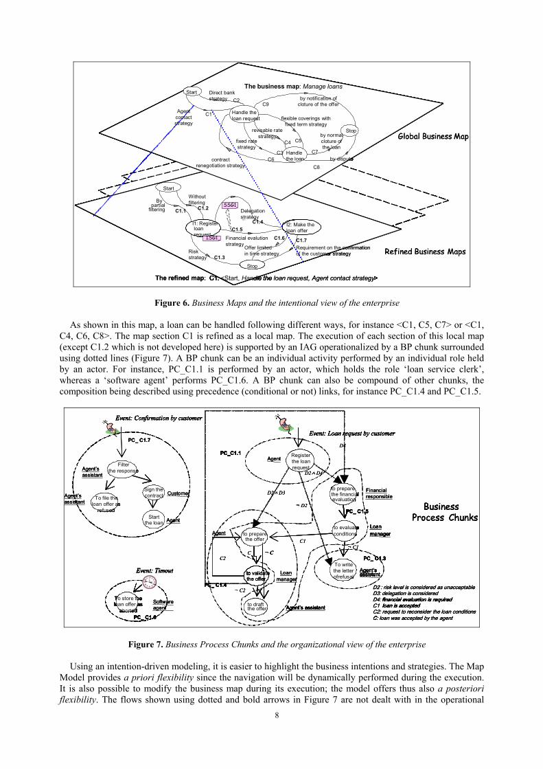
Figure 6. Business Maps and the intentional view of the enterprise As shown in this map, a loan can be handled following different ways, for instance <C1, C5, C7> or <C1,
C4, C6, C8>. The map section C1 is refined as a local map. The execution of each section of this local map (except C1.2 which is not developed here) is supported by an IAG operationalized by a BP chunk surrounded using dotted lines (Figure 7). A BP chunk can be an individual activity performed by an individual role held by an actor. For instance, PC_C1.1 is performed by an actor, which holds the role ‘loan service clerk’, whereas a ‘software agent’ performs PC_C1.6. A BP chunk can also be compound of other chunks, the composition being described using precedence (conditional or not) links, for instance PC_C1.4 and PC_C1.5.
To file theloan offer as
refused
Sign thecontract
Startthe loan
Filterthe responseAgent’s
assistant
Agent’s assistant
Agent
Customer
PC_ C1.7
Event: Confirmation by customer
D2 : risk level is considered as unacceptableD3: delegation is consideredD4: financial evaluation is required: loan is acceptedC2: request to reconsider the loan conditions C: loan was accepted by the agent
Business Process Chunks
Financialresponsible
Loan
Agent’s assistant
Agent’s assistant
¬ C1
C2C
to evaluateconditions
to preparethe financialevaluation
to validatethe offer
to preparethe offer
Agent
Loanmanager
Event: Confirmation by customer
: : : financial evaluation is requiredC1 loan is accepted
C:
Agent’s assistant
Agent’s assistant
¬
to evaluateconditions
to preparethe financialevaluation
to
to preparethe offer
Loanmanager
Registerthe loanrequest
To writethe letterofrefusal
to draftthe offer
¬ D2
D2 ∧ D3
D2 ∧ D4
D4
C1
¬ C
PC_C1.1
PC_ C1.3
PC_ C1.4
PC_ C1.5
Event: Loan request by customer
Agent’s assistant
¬
to evaluateconditions
to preparethe financialevaluation
to preparethe offer
Agent
Registerthe loanrequest
To writethe letterofrefusal
to draftthe offer
¬
∧
∧
¬ C
PC_C1.1
PC_ C1.3
PC_ C1.4
PC_ C1.5
Event: Loan request by customer
To store theloan offer as
abortedSoftware
PC_ C1.6
Event: Timout
To store theloan offer as
aborted agent
PC_ C1.6
Event: Timout
¬ C2
manager
Figure 7. Business Process Chunks and the organizational view of the enterprise Using an intention-driven modeling, it is easier to highlight the business intentions and strategies. The Map
Model provides a priori flexibility since the navigation will be dynamically performed during the execution. It is also possible to modify the business map during its execution; the model offers thus also a posteriori flexibility. The flows shown using dotted and bold arrows in Figure 7 are not dealt with in the operational
8

layer but in the decisional one. We assume in this example that those flow conditions are based on manager decisions which are not (yet) transformed into automated rules based on the status of business objects.
4. The software tool supporting the execution of those models
We developed a software tool for the enactment of BP models defined according to the framework presented above. Our aim is to show the technical feasibility of dealing with intentional and operational process specifications in an interlaced way.
4.1. Software architecture
We designed separate software components to handle (i) intentional representations of BPs provided by business maps and (ii) more rigid parts of those processes specified using activity flows. Four elements are involved:
- The product to be handled, which is a loan offer in the studied case, - Business processes which are intentionally modeled with maps, - The underlying well-structured and more rigid parts of these BPs represented using activity oriented models, - Users (actors) which interact with the tool.
Figure 8 shows the general architecture of the software tool. Components which are shown using gray rectangles will be described in the following sub-sections.
GUI
Individualactivity Individual
activity
Activity flow BusinessProcessChunk
Process Models
Business Map Activity orientedmodels
Map Engine
Activity Manager
Execution components
ProductManager
Product
Interpreted by Interpreted by
Update
Invokes
Manipulates
Integrate
Invokes
ProcessTrace
Reads/updates
shows
IntentionSelection
StrategySelection
Guidance Module
DecisionProcessChunk
Update
Guidelines
Use
Returndata
Uses/Return data
Uses
Uses/Return data
Invokes
Return data
shows
Uses/Return data
Uses/ Return dataGUI
Individualactivity Individual
activity
Activity flow BusinessProcessChunk
Process Models
Business Map Activity orientedmodels
Map Engine
Activity Manager
Execution components
ProductManager
Product
Interpreted by Interpreted by
Update
Invokes
Manipulates
Integrate
Invokes
ProcessTrace
Reads/updates
shows
IntentionSelection
StrategySelection
Guidance Module
DecisionProcessChunk
Update
Guidelines
Use
Returndata
Uses/Return data
Uses
Uses/Return data
Invokes
Return data
shows
Uses/Return data
Uses/ Return data Figure 8. Software architecture
4.1.1. Handling the product under construction: Product Manager
The product is handled by the Product Manager. This component includes a set of functions, each of them being responsible of the execution of a given individual activity. During the execution of each activity, a product will be handled (see the relationship between actions defining an individual activity and business objects in Figure 3). At this stage, the Product Manager is a simulator which does not handle the product resulting from the enactment of a BP but presents, in the terms of the Map Engine, the successive states of the product which is supposed to be handled.
9

When the execution of an activity is terminated, references identifying the handled products are turned over to the software component which invoked the Product Manager. There are two execution components: the Map Engine and the Activity Manager.
4.1.2. Managing intention driven BP representations: Map Engine and Guidance Module
A business map is executed by the Map Engine [12]. The Map Engine takes into account (i) a business map, and (ii) the trace of the executed part of this map. At each stage of map execution, and with respect to the process trace and to the product state, the Map Engine calculates what can be carried out at the next stage of the process enactment. The result is proposed to the user who makes a choice among the options available to him/her. This can be a navigation option (ISG or SSG) or an activity performing option (IAG).
The Map Engine does not impose what should be done, but proposes what could be done. It thus offers a flexible guidance to users. In fact, the dynamic construction of a BP instance is performed by the Map Engine, according to the choices made by the user. This corresponds to the implementation of decision process chunks (see Figure 1) in the Guidance Module. A choice corresponds to a decision to be made and is proposed only to actors which can assume this responsibility.
Afterwards, the execution of the individual activity to be performed is realized by the Product Manager. The latter is invoked by the Map Engine or the Activity Manager according to the nature of the business process chunk (respectively, individual activity or activity flow). Moreover, tasks to be performed have various natures: an IAG can be operationalized by a business process chunk being simple or compound or can be defined at the intentional layer using a refined business map (see Figures 6 and 7). In the last case, the Map Engine calls itself.
4.1.3. Managing well-structured and rigid parts of business processes: Activity Manager
Activity flows are handled by the Activity Manager. Those activities are not just possible choices. Each actor should perform the activity that the Activity Manager posted in his/her activity list. The execution order is defined by activity flow descriptions as shown in dotted circles in Figure 7.
When an activity flow is completely performed, the Activity Manager transmits to the Map Engine the references identifying products resulting from this flow.
4.1.4. Managing the user interface
The Graphical User Interface is the software component which integrates data coming from Map Engine, Activity Manager, Guidance Module and Product Manager. This module makes possible to the user to perceive a common behavior from the entire system.
The GUI displays screens to the user in order he/she can determine the next decision to be taken or the next task to be carried out. The former corresponds to the execution of a decision process chunk (ISG or SSG). The latter corresponds to the execution of a map section (and the corresponding IAG). When a navigation choice was done, the GUI transmits it to the Guidance Module and when values for the product under construction are entered, it transmits them to the Product Manager.
4.2. The vision of the user
Let us now present a partial example of BP execution for the map and the underlying activity flows shown in Figures 6 and 7. The trace of the process execution presented here concerns the ‘handling of a loan request’ using ‘agent contact strategy’ (Figure 6). Several actors are involved. We assume that the ‘Agent’ who is performing the activity ‘Register loan request’ is M. Dubois. Information is required from the borrower M. Ulrich (the client of the BP). The map section which is executed is C1.1 corresponding to the business process chunk PC_C1.1 at the operational level.
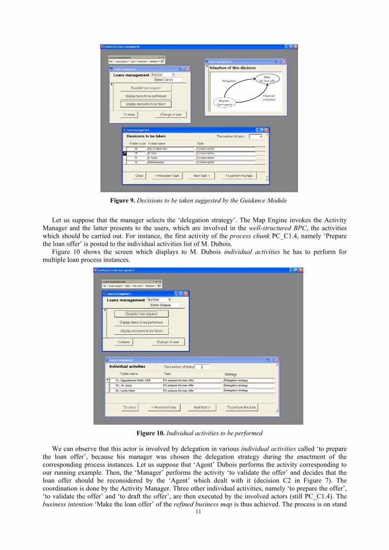
The loan request can be automatically rejected if the admissibility condition is not satisfied (ISG1). Then the ‘Loan manager’ (or a software agent if the decision can be automated) has to take the decision on the manner using which the ‘loan offer can be prepared’ for M. Ulrich (SSG1). Figure 9, proposes to the manager, M. Le Gall, some navigation choices among which he has to choose. For each navigation decision he has to take, this screen shows also the situation of the process enactment. For our running example, the Guidance Module proposes assistance to the manager for the selection of the appropriate strategy, namely delegation or financial evaluation. By clicking on those sections, the manager can visualize the arguments to help him.
10
Registerloan request
Makethe loan offerDelegation
Financialevaluation
Figure 9. Decisions to be taken suggested by the Guidance Module
Let us suppose that the manager selects the ‘delegation strategy’. The Map Engine invokes the Activity
Manager and the latter presents to the users, which are involved in the well-structured BPC, the activities which should be carried out. For instance, the first activity of the process chunk PC_C1.4, namely ‘Prepare the loan offer’ is posted to the individual activities list of M. Dubois.
Figure 10 shows the screen which displays to M. Dubois individual activities he has to perform for multiple loan process instances.
7979
7373
5656
M. UlrichM. Ulrich
LortieLortie HotelHotel
Appartement SARL CRE Appartement SARL CRE
To To prepareprepare thethe loanloan offeroffer
To To prepareprepare thethe loanloan offeroffer
To To prepareprepare thethe loanloan offeroffer DelegationDelegation strategystrategy
DelegationDelegation strategystrategy
DelegationDelegation strategystrategy
33
00
DuboisDubois
Figure 10. Individual activities to be performed
11
We can observe that this actor is involved by delegation in various individual activities called ‘to prepare the loan offer’, because his manager was chosen the delegation strategy during the enactment of the corresponding process instances. Let us suppose that ‘Agent’ Dubois performs the activity corresponding to our running example. Then, the ‘Manager’ performs the activity ‘to validate the offer’ and decides that the loan offer should be reconsidered by the ‘Agent’ which dealt with it (decision C2 in Figure 7). The coordination is done by the Activity Manager. Three other individual activities, namely ‘to prepare the offer’, ‘to validate the offer’ and ‘to draft the offer’, are then executed by the involved actors (still PC_C1.4). The business intention ‘Make the loan offer’ of the refined business map is thus achieved. The process is on stand
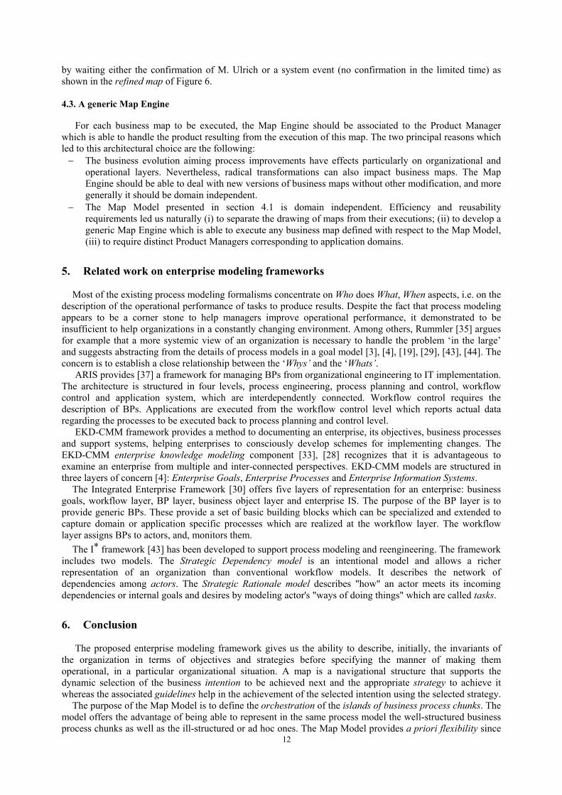
by waiting either the confirmation of M. Ulrich or a system event (no confirmation in the limited time) as shown in the refined map of Figure 6.
4.3. A generic Map Engine
For each business map to be executed, the Map Engine should be associated to the Product Manager which is able to handle the product resulting from the execution of this map. The two principal reasons which led to this architectural choice are the following:
The business evolution aiming process improvements have effects particularly on organizational and operational layers. Nevertheless, radical transformations can also impact business maps. The Map Engine should be able to deal with new versions of business maps without other modification, and more generally it should be domain independent.
−
− The Map Model presented in section 4.1 is domain independent. Efficiency and reusability requirements led us naturally (i) to separate the drawing of maps from their executions; (ii) to develop a generic Map Engine which is able to execute any business map defined with respect to the Map Model, (iii) to require distinct Product Managers corresponding to application domains.
5. Related work on enterprise modeling frameworks
Most of the existing process modeling formalisms concentrate on Who does What, When aspects, i.e. on the description of the operational performance of tasks to produce results. Despite the fact that process modeling appears to be a corner stone to help managers improve operational performance, it demonstrated to be insufficient to help organizations in a constantly changing environment. Among others, Rummler [35] argues for example that a more systemic view of an organization is necessary to handle the problem ‘in the large’ and suggests abstracting from the details of process models in a goal model [3], [4], [19], [29], [43], [44]. The concern is to establish a close relationship between the ‘Whys’ and the ‘Whats’.
ARIS provides [37] a framework for managing BPs from organizational engineering to IT implementation. The architecture is structured in four levels, process engineering, process planning and control, workflow control and application system, which are interdependently connected. Workflow control requires the description of BPs. Applications are executed from the workflow control level which reports actual data regarding the processes to be executed back to process planning and control level.
EKD-CMM framework provides a method to documenting an enterprise, its objectives, business processes and support systems, helping enterprises to consciously develop schemes for implementing changes. The EKD-CMM enterprise knowledge modeling component [33], [28] recognizes that it is advantageous to examine an enterprise from multiple and inter-connected perspectives. EKD-CMM models are structured in three layers of concern [4]: Enterprise Goals, Enterprise Processes and Enterprise Information Systems.
The Integrated Enterprise Framework [30] offers five layers of representation for an enterprise: business goals, workflow layer, BP layer, business object layer and enterprise IS. The purpose of the BP layer is to provide generic BPs. These provide a set of basic building blocks which can be specialized and extended to capture domain or application specific processes which are realized at the workflow layer. The workflow layer assigns BPs to actors, and, monitors them.
The I* framework [43] has been developed to support process modeling and reengineering. The framework includes two models. The Strategic Dependency model is an intentional model and allows a richer representation of an organization than conventional workflow models. It describes the network of dependencies among actors. The Strategic Rationale model describes "how" an actor meets its incoming dependencies or internal goals and desires by modeling actor's "ways of doing things" which are called tasks.
6. Conclusion
The proposed enterprise modeling framework gives us the ability to describe, initially, the invariants of the organization in terms of objectives and strategies before specifying the manner of making them operational, in a particular organizational situation. A map is a navigational structure that supports the dynamic selection of the business intention to be achieved next and the appropriate strategy to achieve it whereas the associated guidelines help in the achievement of the selected intention using the selected strategy.
12
The purpose of the Map Model is to define the orchestration of the islands of business process chunks. The model offers the advantage of being able to represent in the same process model the well-structured business process chunks as well as the ill-structured or ad hoc ones. The Map Model provides a priori flexibility since
the navigation will be dynamically performed during the execution based on user decisions which can not be completely automated, but only guided. The model also offers a posteriori flexibility because it is possible to modify a business map during its execution. The evolution can concern intentions, strategies or the order of the execution of the intentions.
The Map Engine we developed is domain independent and is able to enact any business map. Thanks to the Map Engine and to the product handling simulator, it is now possible to observe the richness of the guidance and dynamic navigation offered by the Map Model during the execution of a business map.
The purpose of the work presented in this paper is to provide a solution to integrate the a priori flexibility in the workflow definitions during the built-time. Nevertheless, the Map Model and the Map Engine allow the modification of business maps during their enactment.
References
1. Agostini, A., De Michelis, G. (2000) A Light Workflow Management System Using Simple Process Models, Computer Supported Cooperative Work: The Journal of Collaborative Computing, Kluwer Academic Publishers, Vol.9.
2. Alonso, G., Agrawal, D., El Abbadi, A., Mohan, C. (1997) Functionality and Limitations of Current Workflow Management Systems, IEEE Expert, 12:5.
3. Antón, A. I., McCracken, W. M., Potts, C. (1994) Goal Decomposition and Scenario Analysis in Business Process Reengineering, CAiSE'94, Utrecht, The Netherlands.
4. Barrios, J., Nurcan, S. (2004) Model Driven Architectures for Enterprise Information Systems, CAISE'04, Letonia, Springer Verlag (pub).
5. Bubenko, J. (1994) Enterprise Modeling. Ingénierie des Systems d' Information, Vol. 2, N° 6.
6. BPML, November 13, 2002, http://www.bpmi.org
7. BPMN Version 1.0, May 3, 2004, http://www.bpmi.org
8. Burlton, R. T. (2001) Business Process Management- Profiting from process, SAMS Publishing.
9. Casati, F., Ceri, S., Pernici, B., Pozzi, G. (1996) Workflow Evolution. ER’96, Cottbus, Germany, Springer Verlag Lecture Notes in Computer Science.
10. Dadam, P., Reichert M., Rinderle S. (2003) Evaluation of Correctness Criteria For Dynamic Workflow Changes, BPM'03, Eindhoven, The Netherlands.
11. Dellen, B., Maurer, F., Pews, G. (1997) Knowledge Based Techniques to Increase the Flexibility of Workflow Management, Data and Knowledge Engineering, North Holland.
12. Edme, M.-H. (2004) Proposition pour la modélisation et le guidage des systèmes d'information multi-facettes MAJECSTIC'04, Octobre, Calais, France.
13. Faustmann, G. (1998) Enforcement vs. Freedom of Action-An Integrated Approach to Flexible Workflow Enactment, Workshop on Adaptive Workflow Systems. CSCW’98, Seattle, USA.
14. Finkelstein, A., Kramer, J., Nuseibeh, B. (eds) (1994) Software Process Modeling and Technology, John Wiley Pub.
15. Gotel, O., Finkelstein, A. USA (1996) An Analysis of the Requirements Traceability Problem. ICRE'94, Colorado Springs.
16. Harel, D. (1990) STATEMATE: A working environment for the development of complex reactive systems. IEEE Transactions on Software Engineering, 16:4.
17. Jarke, M., Mylopoulos, J., Schmidt, J.W., Vassiliou, Y. (1992) DAIDA - An environment for evolving information systems, ACM Transactions on Information Systems, 10:1.
18. Klein, M., Dellarocas, C. (2000) A Knowledge-Based Approach to Handling Exceptions in Workflow Systems. Journal of Computer-Supported Collaborative Work. Special Issue on Adaptive Workflow System, 9(3/4).
19. Lee, J. (1991), “Extending the Potts and Bruns Model for Recording Design Rationale”, ICSE’93, Austin, Texas.
20. Leymann, F., Roller, D. (1999) Production Workflow: Concepts and Techniques, Prentice Hall.
21. Mangan, P., Sadiq, S. (2003) A constraint Specification Approach to Building flexible workflows. Journal of Resarch and Practice in Information Technology, 35:1.
22. Marca, D.A., McGowan, C.L. (1993) IDEF0/SADT: Business Process and Enterprise Modeling. San Diego: Eclectic Solutions, Inc.
23. Mendling J, Nüttgens M (2003) EPC Syntax Validation with XML Schema Languages. In Nüttgens M, Rump FJ, eds., Proceedings of the 2nd GI-Workshop on Business Process Management with Event-Driven Process Chains (EPK 2003), Bamberg, Germany.
24. Meng, J., Su, S.Y.W., Lam, H., Helal, A. (2002) Achieving Dynamic Inter-organizational Workflow Management by
13

14
Integrating Business Processes, Events, and Rules, 35th HICSS, Hawaï.
25. Nilsson, A.G., Tolis, C., Nellborn, C. eds. (1999). Perspectives on Business Modeling. Understanding and Changing Organizations. Springer, Heidelberg.
26. Nurcan, S. (2004) Business Process Modeling for developing Process Oriented IT Systems, The "Business Process Management Tools and Technologies" track, IRMA’04, New Orleans, USA.
27. Nurcan, S., Etien, A., Kaabi, R. Zoukar, I., Rolland, C. (2005) A Strategy Driven Business Process Modeling Approach. Business Process Management Journal, Special issue on "Goal-oriented business process modeling", Emerald. To appear.
28. Nurcan, S., Rolland, C. (2003) A multi-method for defining the organizational change, Information and Software Technology, Elsevier. 45:2.
29. Ould, M. (1995), Business Processes: Modeling and Analysis for Re-engineering and Improvement, John Wiley & Sons, New-York.
30. Papazoglou, M.P., van den Heuvel W.-J. (2000) Configurable business objects for building evolving enterprise models and applications, Business Process Management, Van de Aast W, Desel J., Oberweis A. (eds), Springer.
31. Robinson, W.N. (1996) Goal-Oriented Workflow Analysis and Infrastructure, NSF Workshop on Workflow & Process Automation, Athens, 1996.
32. Rolland, C., Prakash, N., Benjamen A. (1999) A Multi-Model View of Process Modeling, Requirements Engineering Journal, 4:4.
33. Rolland, C., Loucopoulos, P., Grosz, G., Nurcan, S. (1998) A framework for generic patterns dedicated to the management of change in the electricity supply industry, DEXA’98, Workshop on Database and Expert Systems Applications.
34. Rumbaugh, J., Blaha, M., Premerlani, W., Eddy, F., Lorensen, W. (1991) Object Oriented Modeling and Design, Prentice-Hall.
35. Rummler, G.A., Brache, A. P. (1995), Improving Performance, Jossey-Bass Publishers, Indianapolis.
36. Sadiq, S. (2000) On Capturing Exceptions in Workflow Process Models, 4th International Conference on Business Information Systems., Poland. Springer-Verlag.
37. Scheer, A.-W., Nüttgens, M. (2000) ARIS architecture and reference models for business process management, Business Process Management, Van de Aast W, Desel J., Oberweis A. (eds), Springer.
38. UML Resource page, http://www.uml.org/
39. Van der Aalst, W., Desel, J., Oberweis, A. (eds) (2000) Business Process Management – Models, techniques and empirical studies, Springer-Verlag.
40. Van der Aalst, W.M.P., Stoffele, M., Wamelink, J.W.F. (2003), Case Handling in Construction, Automation in Construction, 12:3.
41. WfMC-TC-1011 v3 (1999) Terminology & Glossary, February.
42. Weske, M. (2001) Formal Foundation and Conceptual Design of Dynamic Adaptations in a Workflow Management System. 34th HICSS, Hawaï.
43. Yu, E.S.K., Mylopoulos, J. (1994) From E-R to "A-R" - Modeling Strategic Actor Relationships for Business Process Reengineering, ER’94, Manchester.
44. Yu, E.S.K., Mylopoulos, J. (1996) Using Goals, Rules and Methods to Support Reasoning in Business Process Reengineering, Intelligent Systems in Accounting, Finance and Management, Vol. 5.