INTENT-BASED APPROACH TO VIRTUALIZED …amslaurea.unibo.it/13106/1/thesis.pdf · INTENT-BASED...
104
ALMA MATER STUDIORUM – UNIVERSIT ` A DI BOLOGNA SCHOOL OF ENGINEERING AND ARCHITECTURE MASTER’S DEGREE IN TELECOMMUNICATIONS ENGINEERING INTENT-BASED APPROACH TO VIRTUALIZED INFRASTRUCTURE MANAGEMENT IN SDN/NFV DEPLOYMENTS Master Thesis in Telecommunication Networks Laboratory T Supervisor Prof. WALTER CERRONI Co-supervisor Dr. CHIARA CONTOLI Candidate GIANLUCA DAVOLI SESSION III ACADEMIC YEAR 2015/2016
-
Upload
truongnguyet -
Category
Documents
-
view
227 -
download
2
Transcript of INTENT-BASED APPROACH TO VIRTUALIZED …amslaurea.unibo.it/13106/1/thesis.pdf · INTENT-BASED...

ALMA MATER STUDIORUM – UNIVERSITA DI BOLOGNA
SCHOOL OF ENGINEERING AND ARCHITECTURE
MASTER’S DEGREEIN
TELECOMMUNICATIONS ENGINEERING
INTENT-BASED APPROACH TOVIRTUALIZED INFRASTRUCTURE
MANAGEMENT IN SDN/NFVDEPLOYMENTS
Master Thesisin
Telecommunication Networks Laboratory T
SupervisorProf. WALTER CERRONI
Co-supervisorDr. CHIARA CONTOLI
CandidateGIANLUCA DAVOLI
SESSION IIIACADEMIC YEAR 2015/2016


To those who have always supported me,
in every possible way.


Contents
Sommario vii
Abstract ix
1 Introduction 1
2 Emerging Software-oriented Network Paradigms 5
2.1 Software Defined Networking . . . . . . . . . . . . . . . . . . . . 5
2.1.1 The SDN controller . . . . . . . . . . . . . . . . . . . . . 6
2.1.2 OpenFlow . . . . . . . . . . . . . . . . . . . . . . . . . . 8
2.2 Cloud Computing . . . . . . . . . . . . . . . . . . . . . . . . . . 10
2.3 Network Function Virtualization . . . . . . . . . . . . . . . . . . 11
2.3.1 The NVF-MANO framework . . . . . . . . . . . . . . . . 14
2.4 Software tools . . . . . . . . . . . . . . . . . . . . . . . . . . . . 14
2.4.1 ONOS . . . . . . . . . . . . . . . . . . . . . . . . . . . . 15
2.4.2 Mininet . . . . . . . . . . . . . . . . . . . . . . . . . . . 17
2.4.3 OpenStack . . . . . . . . . . . . . . . . . . . . . . . . . . 18
3 Reference Architecture and Interface Definition 21
3.1 VIM Northbound Interface . . . . . . . . . . . . . . . . . . . . . 23
4 Specific Deployments 27
4.1 SFC in the IoT/Cloud deployment . . . . . . . . . . . . . . . . 27
4.1.1 IoT SDN Domain . . . . . . . . . . . . . . . . . . . . . . 28
4.1.2 OpenFlow and Cloud Domains . . . . . . . . . . . . . . 31
4.2 Dynamic multi-domain SFC . . . . . . . . . . . . . . . . . . . . 35
v

vi CONTENTS
5 OpenFlow/Cloud domain implementation 375.1 Setup of the preliminary local environment . . . . . . . . . . . . 39
5.1.1 Creation of the Virtual Machines . . . . . . . . . . . . . 395.1.2 ONOS Setup . . . . . . . . . . . . . . . . . . . . . . . . 425.1.3 Setup of the IDE . . . . . . . . . . . . . . . . . . . . . . 475.1.4 How to deploy ONOS again . . . . . . . . . . . . . . . . 48
5.2 Setup of the host server . . . . . . . . . . . . . . . . . . . . . . 495.2.1 Configuration of the ONOS VMs . . . . . . . . . . . . . 515.2.2 Setup of the Mininet network . . . . . . . . . . . . . . . 525.2.3 Configuration of the Web server VM . . . . . . . . . . . 535.2.4 POST message handler and server homepage . . . . . . . 555.2.5 Additional configurations on deisnet213 . . . . . . . . . 56
5.3 Modifications on the ONOS application . . . . . . . . . . . . . . 575.3.1 JSON cluster descriptors and requests . . . . . . . . . . 575.3.2 Waypoint Constraint . . . . . . . . . . . . . . . . . . . . 585.3.3 QoS requirements management . . . . . . . . . . . . . . 58
6 Performance evaluation 676.1 Measurements of data plane latency . . . . . . . . . . . . . . . . 676.2 Measurements of control plane delay . . . . . . . . . . . . . . . 70
7 Conclusions 75
A Additional notes, and code 77A.1 SSH on Windows . . . . . . . . . . . . . . . . . . . . . . . . . . 77A.2 Python script that builds the Mininet cluster . . . . . . . . . . . 78A.3 PHP script implementing the POST handler . . . . . . . . . . . 87
Acknowledgements 93

Sommario
Le reti di telecomunicazioni vengono progettate per essere efficienti, traspar-enti, e accessibili all’insieme di utenti piu vasto possibile. Tuttavia, esse riman-gono sistemi complessi, nei quali cooperano un grande numero di componenti,mettendo alla prova la desiderata efficienza, trasparenza e facilita di accesso.
Alcuni paradigmi emergenti, tra cui Software Defined Networking (SDN),Network Function Virtualization (NFV), e Cloud Computing spianano la stradaad un nuovo ventaglio di possibili applicazioni per l’infrastruttura, o a nuovesoluzioni per implementare servizi tradizionali, al prezzo, tuttavia, di aggiun-gere nuovi ambienti necessitanti di coordinazione.
Una delle sfide principali nel fornire concatenazioni end-to-end di servizidistribuiti su multipli domini SDN, NFV e Cloud sta nell’ottenere funzionidi gestione ed orchestrazione unificate. Un aspetto di importanza particolar-mente critica e la definizione di una northbound interface (NBI) ad accessoaperto, non brandizzata, ed interoperabile, che astragga il piu possibile dalletecnologie di piano dati e di piano di controllo specifiche al dominio, facilitandol’accesso all’infrastruttura sottostante, senza pero rinunciare ad un certo gradodi flessibilita e liberta nella programmazione della rete.
In questo documento, viene descritta un’architettura di riferimento, ed es-pansa una NBI basata su intent per l’orchestrazione di servizi end-to-end at-traverso domini tecnologici multipli. Nello specifico, viene considerato comecaso d’uso un deployment di dispositivi per l’Internet of Things (IoT) e i cor-rispondenti servizi di raccolta, elaborazione e pubblicazione dei dati basati suCloud, in grado di distinguere multiple classi di Qualita di Servizio (QoS).Infine, viene descritta e riportata una validazione sperimentale su un test-bedSDN eterogeneo e multi-dominio dell’architettura proposta.
vii

viii SOMMARIO

Abstract
Telecommunication networks are meant to be efficient, transparent, and ac-cessible to the broadest possible set of users. However, they are very complexsystems, in which a large number of components cooperates, posing a challengeto the desired efficiency, transparency and ease of access.
Emerging technological paradigms such as Software Defined Networking(SDN), Network Function Virtualization (NFV) and Cloud Computing openup to a whole new set of possible applications for the infrastructure, or betterways to implement traditional services, but also introduce new environmentsto be controlled.
One of the main challenges in delivering end-to-end service chains acrossmultiple SDN, NFV and Cloud domains is to achieve unified management andorchestration functions. A very critical aspect is the definition of an open,vendor-agnostic, and interoperable northbound interface (NBI) that should beas abstracted as possible from domain-specific data and control plane tech-nologies, making the underlying infrastructure easier to be accessed, while stillallowing a fair amount of flexibility and freedom in programmability of thenetwork.
In this document we describe a reference architecture and expand an intent-based NBI for end-to-end service orchestration across multiple technologicaldomains. More specifically, we consider the use case of an Internet of Things(IoT) infrastructure deployment and the corresponding Cloud-based data col-lection, processing, and publishing services, differentiating multiple Quality ofService (QoS) classes.
Finally we report the experimental validation of the proposed architectureover a heterogeneous, multi-domain SDN test bed.
ix

x ABSTRACT

Chapter 1
Introduction
In the last few years, telecommunications have become as pervasive as they hadnever been before. Connectivity is required everywhere, as an ever-increasingnumber of devices needs to access the Internet to share or retrieve data. How-ever, physical connectivity is just the tip of the iceberg, in the much broaderscenario of end-to-end communication of data. In fact, a larger number ofconnected devices implies a much higher demand for communication resources.Moreover, each application and service running on those devices generates itsown flow of data, which need to be handled and delivered by the underly-ing network infrastructure. This heterogeneity has caused current networksto become very complex to be built and managed, let alone provided withnew features. The deployment of such new features is also obstructed by thephenomenon known as vendor lock-in, caused by the large-scale deploymentof proprietary solutions, which in the long term has led to the ossification ofthe network [1]. It is clear that, in order to face the ever-increasing needsof the users in an efficient way, the network must evolve to a more flexible,customizable, and cost-efficient system.
Software Defined Networking (SDN) plays a major role in the afore-mentioned network evolution. SDN decouples the data plane from the con-trol plane, resulting in a more flexible programmability of communication re-sources. This is achieved by moving the control logic out of the network de-vices, and into an external entity, referred to as SDN Controller, which hostsa running instance of a Network Operating System. This way, infrastructureswhich traditionally suffered from vendor lock-in are turned into communica-tion platforms that are fully programmable via a standardized, open interface
1

2 CHAPTER 1. INTRODUCTION
[2].
Network Function Virtualization (NFV) is often complementary toSDN in tackling the same issues. NFV allows network functionalities to bedispatched as software-based building blocks, which can then be used to buildcomplex Service Function Chains (SFC) in a completely flexible way. Thisalso greatly simplifies the process of maintaining and upgrading the network’sfunctionality, as it is sufficient to act on the original code of the virtualizednetwork function to have it modified on all of its running instances in thenetwork.
A third and important new paradigm in the current network’s evolution isCloud Computing. The paradigm allows service providers to offer networkservices, computing resources and storage space to users, fitting in the sameutility model adopted by electric power or gas suppliers. To this aim, it takesadvantage of both hardware and software resources, which are distributed andvirtualized in the network. [3]
The joint adoption of SDN and NFV provides enhanced flexibility to ser-vice deployment: the SFC, i.e., the sequence of network functions to be appliedto data flows exchanged by a given customer (or set of customers), can be dy-namically controlled and modified over a relatively small time scale, and withsignificantly reduced management burden compared to traditional network in-frastructures [5]. Moreover, the integration with Cloud solutions, as shown inFigure 1.1, contributes to complete virtualization and scalability with resourcesharing and pooling.
The integration of those three paradigms provides unprecedented controland management power over network resources, thus leading to the need ofan efficient solution for the orchestration of the whole multi-paradigm sys-tem. Moreover, due to the pervasiveness of telecommunication services that wementioned at the beginning of this Chapter, heterogeneous and multi-domaindeployments must be taken into account as typical use cases. It is clear thatorchestrating such implementations demands for the development of innova-tive solutions, based on abstractions allowing, on the one hand, the decouplingfrom technological details, and, on the other hand, the preservation of expres-siveness and efficacy in the way the system is programmed, as well as in thecontrol of the network infrastructures. This approach is known as the intent-based approach [6], and it is one of the current top-trending research topics inthe field of networking.
The activities of this thesis focus on the description of the development of

3
an interface for intent-based unified management and orchestration of end-to-end services across heterogeneous, multi-domain deployments.
In Chapter 2 we are going to go deeper in the description of SDN, NFVand Cloud, as well as introducing the main software tools we used for ouractivities.
Chapter 3 is where we present our reference architecture, and we define theNBI we are going to focus on in the rest of the work.
In Chapter 4 we are going to describe the specific deployments we workedon, while in Chapter 5 we cover the implementation details of a part of suchdeployments.
Chapter 6 contains the description and results of the measurements con-ducted for performance evaluation in our test bed.
Finally, in Chapter 7 we state our conclusions on the achieved results andsuggest some possible future developments.

4 CHAPTER 1. INTRODUCTION
Figure 1.1: The interdependency of SDN, NFV and Cloud [4]

Chapter 2
Emerging Software-orientedNetwork Paradigms
As summarized in Chapter 1, Software Defined Networking, Network FunctionVirtualization and Cloud Computing are pushing the world of telecommuni-cation networks to a scenario with an unprecedented central role of softwareaspects. It is worth examining those models a little further before describingthe use we made of them in our activities.
2.1 Software Defined Networking
The SDN paradigm is aimed at supporting the dynamic and scalable comput-ing and storage needs of modern telecommunication environments, by decou-pling the control plane (i.e., the part of the system that makes decisions onhow to forward packets) from the data plane (i.e., the part of the system thatphysically receives, stores and forwards the packets) [7].
In most SDN implementations, the communication between the two planesis carried out by means of the OpenFlow protocol, which allows remote ad-ministration of packet forwarding tables in network devices, by adding, modi-fying and removing packet matching rules and associated actions. More detailson OpenFlow will follow in Section 2.1.2.
In the SDN architecture:
• network control is directly programmable, as it is decoupled from for-warding functionalities, and this abstraction allows administrators to
5

6 CHAPTER 2. EMERGING SOFTWARE-OR. NETWORK PARAD.
dynamically adjust network-wide traffic so as to meet the evolving needof the different flows in the network;
• network intelligence is (logically) centralized in software-based SDN con-trollers that maintain a global view of the network, which appears toapplications and policy engines as a single, logical entity;
• network managers can configure, manage, secure and optimize networkresources very quickly via dynamic, automated SDN programs, whichcan be written by the managers themselves, thanks to the open-sourcenature of the software used;
• network design and operation are simplified because forwarding instruc-tions are provided by SDN controllers instead of multiple, vendor-specificdevices and protocols.
SDN was first standardized in 2011 by the Open Networking Foundation(ONF), which is self-defined as “a user-driven organization dedicated to thepromotion and adoption of SDN, and implementing SDN through open stan-dards, necessary to move the networking industry forward.” [8]
ONF is the entity behind the standardization of the OpenFlow protocol,which also inherently standardizes the interface between now-decoupled controland data planes, enabling SDN deployment.
2.1.1 The SDN controller
As previously stated, the SDN controller is a logically centralized, software-based entity that is in charge of controlling network devices operating in thedata plane; it takes advantage of the global view it has over the network forrunning applications aimed at management, security and optimization of theresources it controls.
As it is shown in Figure 2.1, the SDN controller can be logically placed in aControl Plane located between the Data Plane, where network devices operatethe actual packet forwarding, and the Application Plane, where SDN applica-tions request specific services to the underlying infrastructure, based on thenetwork state or on specific events. However, in order to communicate withthe controller, proper interfaces must be defined. The interface between Ap-plication and Control planes is usually referred to as the Northbound Interface

2.1. SOFTWARE DEFINED NETWORKING 7
Figure 2.1: The role of the SDN controller in the SDN architecture [9]
(NBI), while the one between Control and Data planes, called SDN Control-Data-Plane Interface in Figure 2.1, can also be referred to as the SouthboundInterface (SBI). Both interfaces can be specified and designed to use any com-patible communication protocol. In practice, the most widely-used protocol forController-Device communication through the SBI is the OpenFlow protocol,on which more details will follow in Section 2.1.2.
The activities of our work are focused on the definition of a proper NBIthrough which high-level orchestration and management entities are allowedto control the underlying NFV and SDN platforms and implement dynamicSFC features [10].

8 CHAPTER 2. EMERGING SOFTWARE-OR. NETWORK PARAD.
2.1.2 OpenFlow
In the creators’ own words, OpenFlow is a communications protocol that pro-vides an abstraction of the forwarding plane of a switch or router in the network[11].
Focusing on its main features, OpenFlow:
• brings network control functions out of switches and routers, while al-lowing to directly access and manipulate the forwarding plane of thosedevices;
• specifies basic primitives that can be used by an external software appli-cation to actually program the forwarding plane of network devices, justlike the instruction set of a CPU would program a computer system;
• works on a per-flow basis to identify network traffic;
• forwards flows according to pre-defined match rules statically or dynam-ically programmed by the SDN control software.
OpenFlow can be used both in a reactive and in a proactive way. In theformer case, whenever an OpenFlow-enabled device receives a data packet itdoes not know how to handle, it wraps the data packet into an OpenFlow Pack-etIn message, to be sent to the relevant network controller. Upon reception ofthis message, the controller can analyze the packet and reply to the device itcame from with an OpenFlow FlowMod message, containing, along with theoriginal data packet that generated the PacketIn event, a set of matching rulesand actions to be performed upon reception of data packets with similar char-acteristics. A scheme of the control message received by the device is shownin Figure 2.2. The device then installs the new flow rule into its flow table,so that, if it receives a data packet that matches one of the entries of its flowtable, it applies the corresponding sequence of actions, without the need ofquerying the controller again. If the device has to handle a sequence of similarpackets, as in a ping sequence, the first packet will take a longer time to beforwarded than the following packets in the sequence will. An example of thistypical behavior is shown in Listing 2.1, where we have the output of a ping
session through an OpenFlow/SDN domain.

2.1. SOFTWARE DEFINED NETWORKING 9
Figure 2.2: The OpenFlow table [12]
PING 10.0.0.8 (10.0.0.8) 56(84) bytes of data.
64 bytes from 10.0.0.8: icmp_seq =1 ttl =64 time =29.1 ms
64 bytes from 10.0.0.8: icmp_seq =2 ttl =64 time =0.647 ms
64 bytes from 10.0.0.8: icmp_seq =3 ttl =64 time =0.055 ms
64 bytes from 10.0.0.8: icmp_seq =4 ttl =64 time =0.052 ms
Listing 2.1: Start of a ping session in a SDN domain with reactive forwarding
We can observe that the first packet of the ping sequence has a RoundTrip Time (RTT) that is close to 30 ms, while the following packets’ RTTis smaller than 1 ms. This is due to the fact that, when the first packet ofthe sequence traverses each switch, those devices must contact the controllerto be instructed on what to do with it, then receive and install new flowrules in their flow table, and finally proceed to forward the packet. When thefollowing packets in the sequence traverse the switches, the devices will notneed to contact the controller, as they will act based on the new flow rules,resulting in a much faster forwarding decision phase.
On the other hand, while using OpenFlow in a proactive way, flow rules are

10 CHAPTER 2. EMERGING SOFTWARE-OR. NETWORK PARAD.
installed before actual traffic reaches the network devices. This approach willobviously enhance data plane latency, as no communication to the controller isneeded for the traffic which complies with the filters of the installed flow rules,but this is paid in terms of reduced flexibility. In fact, it is often impossible toinstall very selective (i.e., precise) and correct flow rules by acting proactively,as in most scenarios many details on the incoming traffic (e.g., client-sideTCP port number) are not known a priori. For this reason, when acting ina proactive way, flows are defined with a larger granularity (i.e., a smallerprecision) than they would have with a reactive approach.
More details on the OpenFlow protocol and its versions are available onthe documents and standards produced by ONF [13].
2.2 Cloud Computing
Cloud Computing, often referred to simply as Cloud, is a paradigm that aimsat enabling ubiquitous, on-demand access to a shared pool of configurablecomputing and infrastructure resources [14].
As already mentioned in the Chapter 1, the paradigm allows network ser-vice providers to offer their services in the same way as utility services, suchas electric power and gas are distributed: the end users pay for what theyget. In order to do so, Cloud Computing takes advantage of both hardwareand software resources, which are distributed and virtualized in the network[3], and is supported in doing so by the high data rates made available bywide-band connection.
End users expect the resources offered by the Cloud to be instantiatedand used in a transparent, seamless way. Those resources, however, may begeographically distributed all over the world, imposing high demands on theinterconnecting network, in terms of configuration delay, let alone latency andreliability in the data plane. This is where SDN comes into play, allowingthe resources to quickly configure or re-configure in order to match the user’srequests. Moreover, thanks to the centralized management approach that theSDN paradigm offers, data flows can be dynamically steered to the best pathfrom the user to the server hosting the resources.

2.3. NETWORK FUNCTION VIRTUALIZATION 11
2.3 Network Function Virtualization
NFV is a network architecture paradigm that uses virtualization technologiesin order to obtain a new way of designing, deploying and managing networkservices. [15]
A given service can be decomposed in a set of Virtual Network Functions(VNFs) that can be implemented in software and run on general purpose phys-ical servers, without the need of specialized hardware. For example, a singleVNF can be implemented as a set of software entities (i.e., different modulesof the function), running on one or more Virtual Machines (VMs), hosted byone or more physical servers. The VNFs can be relocated (i.e., migrated) tonew network locations, without the need to purchase new hardware.
It is also possible for VNFs to be run on physical machines without vir-tualization of resources. However, two of the strongest advantages of NFVare flexibility and resource efficiency, which are inherently achievable throughresource virtualization.
In general, NFV brings the benefits of the Cloud Computing approach toenvironment of telecommunication networks. In fact, the advantages intro-duced by NFV in comparison to the traditional scenario are:
• independence of software from hardware, which allows for separate de-velopment and maintenance of the two components;
• flexibility of the services offered by the network, as VNFs can be rear-ranged and upgraded very rapidly, while maintaining the same hardwareplatform;
• dynamic and more accurate scaling of the capabilities of the whole ser-vice, according to the actual load carried by the network in a givenmoment.
The NFV architecture has been described by ETSI in [16], and a schemeof the NFV reference architectural framework is shown in Figure 2.4. Theidentified functional blocks are the following ones:
– Virtualized Network Functions (VNF), which are virtualized versions ofnetwork functions in a legacy non-virtualized network, and may includeelements of the core network (e.g., the Mobile Management Entity in the3GPP Evolved Packet Core) as well as elements in a home network (e.g.,firewalls);

12 CHAPTER 2. EMERGING SOFTWARE-OR. NETWORK PARAD.
Figure 2.3: Comparison between the traditional approach and the NFV ap-proach, simplified
– Element Management System (EMS), which performs the managementfunctionality for one or multiple VNFs;
– NFV infrastructure, which is the set of all hardware and software com-ponents on top of which VNFs are deployed, managed and executed,including:
– hardware resources, assumed to be Commercial Off-The-Shelf phys-ical equipment, providing processing, storage and connectivity toVNFs through the Virtualization Layer;
– Virtualization Layer, such as an hypervisor, which abstracts thephysical resources, so as to enable the software that implement theVNFs to use the underlying infrastructure, and provide the virtu-alized resources to the VNF;
– Virtualized Infrastructure Manager(s) (VIM), which comprises the func-tionalities that are used to control and manage the interaction of a VNFwith computing, storage and network resources under its authority, as

2.3. NETWORK FUNCTION VIRTUALIZATION 13
well as their virtualization;– Orchestrator, which is in charge of the orchestration and management of
NFV infrastructure and software resources;– VNF Manager(s), which are responsible for VNF lifecycle management
(e.g. instantiation, update, query, scaling, termination;– Service, VNF and Infrastructure Description, which is a data set that
provides information regarding the VNF deployment template, VNF For-warding Graph, service-related information, and NFV infrastructure in-formation models;
– Operation and Business Support Systems (OSS/BSS), which are used byan Operator to support a range of telecommunication services.
Figure 2.4: NFV reference architectural framework [16]
In Figure 2.4, the main reference points (i.e., the logical interconnections)that are in the scope of NFV are shown by solid lines. In our work, we are

14 CHAPTER 2. EMERGING SOFTWARE-OR. NETWORK PARAD.
going to focus mostly on the reference points labeled as Or-Vi and Nf-Vi inthe figure. The former interconnection is used for carrying resource reservationand/or allocation requests by the Orchestrator, virtualized hardware resourceconfiguration, and state information exchange (e.g., events). The latter oneis used for specific assignment of virtualized resources in response to resourceallocation requests, forwarding of virtualized resources state information, andhardware resource configuration and state information exchange (e.g., events).
2.3.1 The NVF-MANO framework
Due to the decoupling of the Network Functions software from the NFV In-frastructure (NFVI), coordination between resources requested by the VNFsis needed. The Network Functions Virtualization Management and Orchestra-tion (NFV-MANO) architectural framework, described by ETSI in [17], hasthe role of managing the NFVI while orchestrating the allocation of resourcesneeded by the VNFs. A functional-level representation of the MANO frame-work is shown in Figure 2.5.
The main functional blocks it encompasses have already been describedin the previous section. The importance of this framework is in the evenmore general view it yields over the considered SDN/NFV deployment. Ahierarchical scheme of the architecture is shown in Figure 2.6, which highlightsthe role of SDN Controllers in a multi-domain scenario. In that scheme, wecan see all the functional blocks and reference point we are going to focus onin the activities presented in the following Chapters. For instance, the genericdeployment we present as our reference architecture in Figure 3.1 is actuallya slightly differently characterized version of the one presented in Figure 2.6.
2.4 Software tools
In this section we are going to have an overview on the main software toolsthat have been used in our activities. We will have a brief look at ONOS,the network controller, Mininet, the network emulator, and OpenStack, theCloud operating system.

2.4. SOFTWARE TOOLS 15
Figure 2.5: The NFV-MANO architectural framework with ref. points [17]
2.4.1 ONOS
ONOS, short for Open Network Operating System, is, as the name suggests,an open-source Network OS (NetOS), developed and maintained as part of theONOS project, whose mission is “to produce the Open Source Network Oper-ating System that will enable service providers to build real Software DefinedNetworks” [18].
ONOS is able to provide the control plane for a software-defined network,managing network components, such as switches and links, and running soft-ware programs or modules to provide communication services to end hosts andneighboring networks [19].
As a NetOS, ONOS aims at:
• providing APIs and abstractions, resource allocation, and permissions,as well as user-facing software such as a CLI, a GUI, and system appli-cations;

16 CHAPTER 2. EMERGING SOFTWARE-OR. NETWORK PARAD.
Figure 2.6: Hierarchical view in SDN multi-domain scenario [17]
• managing the entire network rather than a single device, which can dra-matically simplify management, configuration, and deployment of newsoftware, hardware, and services;
• acting as an extensible, modular, distributed SDN controller.
ONOS can run as a distributed system across multiple servers, allowingit to use their combined CPU and memory resources while providing faulttolerance in the case of server failure, and potentially supporting live upgradesof hardware and software without interrupting network traffic.
A scheme of the ONOS internal architecture, along with some examples ofexternal agents both towards the Application plane and the Data plane areshown in Figure 2.7.
The ONOS kernel and core services, as well as ONOS applications, arewritten in Java as bundles that are loaded into the Karaf OSGi container.

2.4. SOFTWARE TOOLS 17
Figure 2.7: Our contribution in the ONOS subsystem
OSGi is a component system for Java that allows modules to be installed andrun dynamically in a single Java VM (JVM). Since ONOS runs in the JVM,it can run on several underlying OS platforms.
Our contribution to the ONOS project, the ONOS application implement-ing the intent-based REST NBI, is circled in Figure 2.7.
2.4.2 Mininet
Mininet is a network emulator which is able to emulate a linked set of virtualhosts, switches, controllers. Mininet hosts run standard Linux network soft-ware, and its switches support OpenFlow for highly flexible custom routingand SDN [20].
Mininet supports research, development, learning, prototyping, testing, de-bugging, and any other tasks that could benefit from having a complete ex-perimental network on a laptop or other PC.
In order to achieve that, Mininet:
• provides a simple and inexpensive network testbed for developing Open-Flow applications;
• enables multiple concurrent developers to work independently on thesame topology;
• supports system-level regression tests, which are repeatable and easilypackaged;
18 CHAPTER 2. EMERGING SOFTWARE-OR. NETWORK PARAD.
• enables complex topology testing, without the need to wire up a physicalnetwork;
• includes a CLI that is topology-aware and OpenFlow-aware, for debug-ging or running network-wide tests;
• supports arbitrary custom topologies, and includes a basic set of param-etrized topologies which is usable out-of-the-box without programming;
• provides a straightforward and extensible Python API for network cre-ation and experimentation.
In a nutshell, Mininet provides an easy way to get correct system behaviorand performance (to the extent supported by the underlying hardware), andto experiment with topologies. Some examples of Mininet’s built-in topologiesare shown in Figure 2.8.
Mininet networks run “real code”, including standard Unix/Linux networkapplications, as well as the real Linux kernel and network stack. Thanks tothis, the code developed and tested on Mininet (for an OpenFlow controller,modified switch, or host) can move to a real system with minimal changes,for real-world testing, performance evaluation, and deployment. Most im-portantly, this means that a design that works in Mininet can usually movedirectly to hardware switches for line-rate packet forwarding.
2.4.3 OpenStack
OpenStack [21] is a Cloud operating system that allows for the managementof a Cloud platform. Such a platform is a cluster of physical machines whichhost instances of compute and storage nodes, offered to the user as a service.
OpenStack provides a convenient GUI in the form of a dashboard, that canbe used to simplify the process creation and management of the instances, aswell as a CLI, which allows for greater precision in the specifications on theresources to be allocated.
A single user, who represents a tenant, can create a new network in thecluster, and define one or more subnets over it. Then, the user can create anew instance of a VM, placing it on the desired network or subnetwork. Fromthat moment on, the VM will be accessible as a regular machine, through thenetwork it is connected to.

2.4. SOFTWARE TOOLS 19
OpenStack also supports multi-tenancy, that is the co-existence of multipleusers in the same cluster, which are mutually isolated through the use ofseparate VLANs and namespaces [3].

20 CHAPTER 2. EMERGING SOFTWARE-OR. NETWORK PARAD.
(a) Single ( --topo single,3 )
(b) Linear ( --topo linear,3 )
(c) 2-level tree ( --topo tree,2 )
(d) 3-level tree ( --topo tree,3 )
Figure 2.8: Examples of network topologies emulated in Mininet

Chapter 3
Reference Architecture andInterface Definition
In this chapter we will describe the reference architecture of our scenario, thenthe proposed NBI, and finally the domains relevant to the activities of thisthesis.
Figure 3.1: Reference multi-domain SDN/NFV architecture, in general
Our reference architecture is shown in Figure 3.1, and it is inspired by the
21

22 CHAPTER 3. REF. ARCHITECTURE AND INTERFACE DEF.
ETSI NFV specifications, with particular reference to the Management andOrchestration (MANO) framework [17], which has been presented in Section2.3.1.
This way, the proposed architecture is compliant with the most relevantNFV standard initiative to date, and it can be easily extended to include anyfurther SDN/NFV domain and technology as part of the underlying virtualizedinfrastructure.
Each of the SDN/NFV domains shown in Figure 4.1 consists of a technology-specific infrastructure, including:
• data plane components, such as IoT nodes and gateways, SDN switches,virtual machines running in Cloud computing nodes, physical and virtualinterconnecting links; these components provide the network, compute,and storage resources to be orchestrated;
• control plane components, such as SDN and Cloud controllers with re-lated data stores and interfaces; these components are responsible forproper VNF deployment and traffic steering across VNFs and domains;
• management plane components, such as Virtualized Infrastructure Man-agers (VIMs) specialized for managing resources in the IoT-based SDNinfrastructure, the wired SDN infrastructure, and the Cloud infrastruc-ture; based on the available implementations, some of these componentscould be in charge of multiple domains, as in the case of the SDN/CloudVIM in Figure 4.1.
The overarching VNF Manager (VNFM) and NFV Orchestrator (NFVO)components are responsible for programming the underlying VIMs and infras-tructure controllers in order to implement and maintain the required servicechains in a consistent and effective way, for both intra- and inter-domain sce-narios. While technology- and domain-specific northbound (NBI) and south-bound interfaces (SBI) are used inside each domain to efficiently control andmanage the relevant components, the design of the overarching VNFM andNFVO should be as technology-agnostic as possible, so that a service chainto be deployed can be specified by a customer using a high-level, intent-baseddescription of the service itself. This would also allow the proposed archi-tecture to be more general and capable of being extended to different SDNtechnologies and domains.
3.1. VIM NORTHBOUND INTERFACE 23
As it is argued in [2], in order to achieve such generality in the high-level management and orchestration components, the act of decoupling serviceabstractions from the underlying technology-specific resources should be per-formed mainly by the VIMs. Therefore, the concept of interactions based onintents is extended to the NBI offered by the VIMs, which should be defined asan open and abstracted interface, independent of the specific technology usedin the underlying domains.
It is important to outline that this reference architecture considers also thepossibility that SDN domains are interconnected through non-SDN domains.This assumption stems from the fact that it appears reasonable that a networkoperator will deploy SDN technologies mainly within data center infrastruc-tures where the VNF resources will be located e.g., in the operators points ofpresence or central offices rather than in backbone networks. In this case, traf-fic flows that must traverse a number of SDN domains can be properly routedby adopting some form of tunneling or overlay network technology across thenon-SDN domains, such as the emerging Network Service Header (NSH) [22].
NSH describes a dataplane header used to carry information along a servicepath, thus creating a transport-independent service plane. More specifically, itdecouples the service topology from the actual network topology, making eachservice function an identifiable resource available for consumption from anylocation in the network. Some more details on NSH is reported in Section 4.2
3.1 VIM Northbound Interface
An intent-based NBI must allow the user to specify policies (i.e., “what todo”) rather than mechanism (i.e., “how to do it”).
When a given service specification is received, the platform managementand orchestration functions must convert that request into a suitable servicegraph and pass it to the relevant VIMs in charge of the underlying infrastruc-tures and domains involved in the service composition. Then each VIM mustcoordinate the respective Cloud and network controllers in order to:
• verify availability and location in the Cloud infrastructure of the VNFsrequired to compose the specified service, instantiating new ones if needed;
• program traffic steering rules in the network infrastructure to deploy asuitable network forwarding path.

24 CHAPTER 3. REF. ARCHITECTURE AND INTERFACE DEF.
EdgeRouter
User
DPI/IDS
TrafficShaper
WANAccel.
WANAccel.
EdgeRouter
EdgeRouter
User
DPI/IDS
WANAccel.
WANAccel.
EdgeRouter
Content/Service
Content/Service
Figure 3.2: Example of a Service Function Chain
In order to provide an abstracted yet flexible definition of the specifiedservice graph, without knowledge of the technology-specific details (such asdevices, ports, addresses, etc.), the NBI exposed by the test bed should allowto specify not only the sequence but also the nature of the different VNFs to betraversed, which is strictly related to the service component they implement,as well as other peculiar characteristics of the service itself, such as quality ofservice (QoS) metrics and thresholds.
As a first attempt to define the NBI, the following abstractions can beconsidered:
• a QoS feature can be defined in terms of a QoS metric that is relevant tothe service specified; in the example discussed above the relevant metricis guaranteed bit rate;
• a QoS threshold can be specified for the QoS metric of interest; in theexample, a minimum bit rate value to be guaranteed can be specified;
• a VNF can be terminating or forwarding a given traffic flow; in theexample of Figure 3.2, the Deep Packet Inspector/Intrusion DetectionSystem (DPI/IDS) is terminating the flow, whereas the traffic shaperand the WAN accelerator are forwarding it;
• a forwarding VNF can be port symmetric or port asymmetric, dependingon whether or not it can be traversed by a given traffic flow regardless

3.1. VIM NORTHBOUND INTERFACE 25
of which port is used as input or output; in the example, the WANaccelerator is port asymmetric, because it compresses or decompressesdata based on the input port used, whereas the traffic shaper can beconsidered port symmetric, if we assume that the shaping function isapplied to any output of the VNF;
• a VNF can be path symmetric or path asymmetric, depending on whetheror not it must be traversed by a given flow in both upstream and down-stream directions; in the example, according to the service requirements,the WAN accelerator and the DPI/IDS are path symmetric, whereas thetraffic shaper is path asymmetric.
In order to implement the aforementioned abstractions, we define a sort ofETSI MANO deployment template adopting the well-known JSON format. Aservice chain is therefore defined in the following way:
{
"src": "node_value",
"dst": "node_value",
"qos": "qos_type",
"qos-thr": "qos_value",
"vnfList": [vnf],
"dupList": [dup]
}
where:
• src and dst represent the endpoint nodes of the service chain, eitherglobal or limited to a given VIM domain;
• node_value is a text string that contains a high-level unique identifierof a node known to both orchestrator and VIM;
• qos represents the QoS feature to be provided with the service chain,and its value, qos_type, is a text string that contains a high-level uniqueidentifier of a QoS metric known to both orchestrator and VIM
• qos-thr represents the QoS threshold to be applied to the specified met-ric, and its value, qos_value, is the actual value assigned to the thresh-old;
26 CHAPTER 3. REF. ARCHITECTURE AND INTERFACE DEF.
• vnfList is the ordered list of VNFs to be traversed according to thespecified service;
• dupList is the list of VNFs towards which the traffic flow must be du-plicated.
Each VNF is described in terms of its topological abstractions with thefollowing template:
vnf ::= {
"name": "node_value",
"terminal ": "bool_value",
"port_sym ": "bool_value",
"path_sym ": "bool_value"
} | ε
where bool_value is a text string representing either a Boolean or a nullvalue, and the symbol ε indicates the possibility that vnf is an empty element.Considering that some network functions (e.g., DPI) require traffic flows tobe mirrored, the (possibly empty) list of VNFs towards which the traffic flowmust be duplicated is specified with the following template:
dup ::= {"name": "node_value "} | ε
The NBI offered by VIMs can be implemented through the mechanisms ofa REST API, and should provide the following methods:
• a method to define a new service chain;
• a method to update an existing service chain;
• a method to delete an existing service chain.
These actions are basically in line with the operations foreseen by the ETSIMANO specifications, with reference to the interface between NFVO and VIM.It is worth highlighting that the NBI description given above is indeed basedon the concept of intent. QoS metric, VNFs and service chains are specified ina high-level, policy-oriented format without any knowledge of the technology-specific details. A non-intent-based description of a service chain, e.g. usingthe OpenFlow expressiveness to steer traffic flows and compose the network for-warding path, would require the customer to specify multiple flow rules in eachforwarding device for each traffic direction, involving technology-dependent de-tails such as IP and MAC addresses, device identifiers and port numbers.

Chapter 4
Specific Deployments
The NBI defined in Chapter 3 is used in this Chapter to specify an IoT datagathering service crossing two different SDN domains and an NFV chain, asper the architecture in Figure 4.1.
For the use case considered here, the high-level QoS features offered by theSDN/NFV platform include minimum latency and high reliability classes,with the possibility to specify a threshold for the relevant metric.
Although the above intent-based NBI definition is common to all VIMsconsidered in our use case, the orchestrator must specify different contentfor each VIM depending on the specific resources to be programmed and thespecific segment of the service chain to be deployed in each domain.
4.1 Service Function Chaining
in the IoT/Cloud deployment
Our aim is to obtain an intent-based, technology-independent, north-boundinterface (NBI) for end-to-end service management and orchestration acrossmultiple technological domains, possibly including both SDN and non-SDNdomains.
In comparison to Figure 3.1, in Figure 4.1 we present a specialized versionof the reference architecture, specific to the use case of IoT data collection andrelated Cloud-based consumption.
By going further into detail, we obtain the scheme of the actual test bedwe developed to demonstrate multi-domain SDN/NFV management and or-chestration, shown in Figure 4.2
27

28 CHAPTER 4. SPECIFIC DEPLOYMENTS
IoT SDN Controller
SDN Controller
VNF
VNF
VNF Manager (VNFM) and NFV Orchestrator (NFVO)
IoT VIMSDN/Cloud VIM
CloudControllerDB
GW1
IoT Coord1
GWN
IoT CoordN
IoT Network 1
IoT Network N
…
IoT SDN Domain
SDN Domain Cloud Domain
VIM Intent-based NBI(Vnfm-Vi, Or-Vi)
Network/Cloud Controller NBI(Nf-Vi)
Technology-specific SBI
Figure 4.1: Reference multi-domain SDN/NFV architecture, specialized forthe presented use case
4.1.1 IoT SDN Domain
The IoT SDN domain included in the architecture of Figure 4.2 is composedof:
• a VIM able to manage components and resources in the IoT domain;
• an IoT SDN controller (IoTC), implementing the software-defined controlplane of the IoT domain;
• a set of IoT networks, where different devices send the measured data viamulti-hop paths to a coordinator node that forwards them to the finalconsumer.
Since the different IoT networks will possibly use different technologies(e.g., Zigbee, LoraWAN, 6LowPAN, etc.), each IoT coordinator will be con-nected to a specific gateway (GW) in charge of forwarding data outside theIoT domain.
When a service request is received from the high-level management andorchestration functions, the IoT VIM gets access to the IoTC. As it is shown in

4.1. SFC IN THE IOT/CLOUD DEPLOYMENT 29
Controller
Database
AdaptationIoT/IP GW
IoT Network
VNF Manager (VNFM) and NFV Orchestrator (NFVO)
ONOS VIM
IoT VIM
HTTP
HTTP
HTTP REST
HTTP REST
HTTP
Control/Management Plane
Data Plane
OpenFlow
Cloud (emulated)
OpenFlowNetwork
Figure 4.2: the NFV/SDN test bed setup developed
Figure 4.2, one of the components of the controller is a database, which storesinformation about devices of the different networks, such as how to reachthem (i.e., the IP address of the corresponding GW), the service provided,and the related QoS feature that could be guaranteed. The VIM tries to mapthe incoming request with the resource knowledge available in the database, inorder to select the proper IoT device(s) to forward the request to. According tothe decision taken, the IoTC will program the selected IoT network(s) to makesure that the requested QoS would be guaranteed, and forward the request tothe identified GW(s).
The IoT VIM and database
The VIM is capable of handling requests containing either the particular IoTdevice to be queried, or a high-level description of the service requested bythe customer, together with some other possible specification related to theQoS (in terms of reliability or maximum latency). Let us consider the case ofa customer that wishes to periodically collect temperature values in a givenroom and monitor them by means of a processing/publishing service called

30 CHAPTER 4. SPECIFIC DEPLOYMENTS
ServP running as a VNF in the Cloud domain. Assume that the customer isinterested in having a complete record of the measured temperature request,thus requiring a high-reliable service. Then the intent-based request sent tothe IoT VIM, expressed according to the JSON format specified in Section 3.1,could be as shown in Listing 4.1.
{
"src": "ServP",
"dst": "Temperature Room X",
"qos": "SR",
"qos -thr": "90%",
"vnfList ": "null",
"dupList ": "null"
}
Listing 4.1: Example of request sent to the IoT VIM
In the IoT domain, following the typical IoT device query approach,src represents the source of the query, that is the final consumer of the data tobe collected. In our example, this is the processing/publishing service in theCloud. On the other hand, dst represents the final endpoint of the query, thatcould be one or multiple IoT devices. This text string may contain a uniqueidentifier of a specific IoT device, or a high-level intent-based description ofthe requested service. The second option is used in our example above. Thefield qos represents the requested QoS feature either in terms of latency, ex-pressed as data plane RTT, or reliability, that is the probability of successfullyreceiving the data from that device. In our IoT VIM implementation, qos
may assume the values of real time (RT), non real time (NRT), strictly reliable(SR), or loosely reliable (LR). If needed, the user may also provide qos-thr,representing either the maximum tolerable latency or the minimum requestedthroughput/reliability. In the example above, SR with a 90% threshold isrequested. Finally, vnfList and dupList are not specified in the examplebecause we assume that the orchestrator opted for VNFs located in the Clouddomain.
At this point the VIM checks in the database if the destination the user islooking for is present, and if the requested QoS (if any) could be satisfied.
When the IoTC receives a new measurement from a device, the data isstored in the database, along with the instant in which it was received. Oncea new request for the same device arrives the VIM checks the timestamp anddecides whether the data needs to be updated or not (if not, the value isimmediately returned).

4.1. SFC IN THE IOT/CLOUD DEPLOYMENT 31
With reference to the QoS, it is important to underline that in case thesame device could reach the IoT coordinator via different paths (e.g., havingdifferent number of hops), the corresponding QoS values are stored in thedatabase.
The IoT controller and network
The IoT controller is responsible for gathering information from sensor devices,maintaining a representation of the network, and establishing routing paths.
In order to achieve the decoupling of the control plane from the data plane,it is fundamental for each device to be able to discover a path towards thecoordinator. This is done during the network initialization phase. Requestscoming from the VIM are forwarded by the IoTC to the proper IoT coordinator,along with the information about the selected path connecting the coordinatorand the intended device to be setup to guarantee the requested QoS. Thedetails on how this works are covered in [23].
4.1.2 OpenFlow and Cloud Domains
In this section we consider both the wired SDN domain and the Cloud Com-puting domain depicted in Figure 4.1, assuming that they are managed by asingle SDN/Cloud VIM. The data plane topology assumed for the considereduse case is shown in Figure 4.3. An OpenFlow-based SDN infrastructure isassumed to be in charge of the connectivity within the Cloud domain as well,thus providing programmable traffic steering functionality to VNF chains. Allthe switches included in the topology (s1, s2, . . . , s7) are OpenFlow-enableddevices and are governed by an SDN controller (e.g., ONOS), whereas the com-puting infrastructure is managed through a Cloud platform (e.g., OpenStack).
Switch s6 is an edge device connecting the IoT gateways in the IoT SDNdomain to the Cloud network. Router vrl is the (virtual) edge router of the(virtual) tenant network responsible for the connectivity within the Cloud do-main of the requested IoT data collection service. Switches s1 to s5 are eitherphysical or virtual switches used by the tenant network for VNF connectivity.Two VNFs are deployed in the Cloud: chk performs integrity checks on thecollected data for improved reliability, whereas bck is used to store backupcopies of the collected data. Router vrr is the (virtual) edge router of the(possibly different) tenant responsible for the IoT data collection, processing,

32 CHAPTER 4. SPECIFIC DEPLOYMENTS
Cloud Infrastructure
Figure 4.3: data plane topology of the OpenFlow and Cloud domains consid-ered for the use case
and publishing services. Switch s7 is a (virtual) switch in the latter tenant’snetwork, providing layer-2 connectivity to the server ServP where collecteddata are processed and published.
According to the QoS features of the use case considered here, the connec-tivity service offers two different paths in the OpenFlow domain. One path ischaracterized by minimum latency, where switches are configured with smallbuffers being continuously monitored by the SDN controller for possible con-gestion, and such that no VNF processing is performed, which could introduceadditional delays. The other path is dedicated to highly reliable traffic flows,where switches have large buffers to reduce losses, and data are processed bychk and duplicated at switch s2 in order to be stored in bck.
Therefore, depending on the QoS feature requested by the customer, thehigh level management and orchestration functions can specify two differentservice chains. Assuming that, based on the interaction between the orches-trator and the IoT VIM, incoming data will be collected from IoT network kand then forwarded to ServP, according to the JSON format specified in Sec-tion 3.1 the intent-based request to the SDN/Cloud VIM NBI could be the oneshown in Listing 4.2 for the minimum latency QoS feature, or the one shownin Listing 4.3 for the high reliability QoS feature. The SDN controller must

4.1. SFC IN THE IOT/CLOUD DEPLOYMENT 33
implement a data plane monitoring service to make sure that, in the formercase, the minimum latency path guarantees the requested maximum delay of10 ms, whereas in the latter case the VNFs inserted in the service chain andthe high reliability path ensure the required 99% accuracy.
For the sake of completeness, we remark that the data paths depicted inFigure 4.2 are those for the case in which the QoS class is set to high reliability.
{
"src": "IoT -GW[k]",
"dst": "ServP",
"qos": "Max delay",
"qos -thr": "10 ms",
"vnfList ": "null",
"dupList ": "null"
}
Listing 4.2: Request for minimum latency path
{
"src": "IoT -GW[k]",
"dst": "ServP",
"qos": "Reliability",
"qos -thr": "99%",
"vnfList ": [chk , bck]
"dupList ": [bck]
}
chk ::= {
"name": "chk",
"terminal ": "false",
"port_sym ": "true",
"path_sym ": "false"
}
bck ::= {
"name": "bck",
"terminal ": "true",
"port_sym ": "null",
"path_sym ": "false"
}
Listing 4.3: Request for high reliability path
We developed the VIM for the SDN/Cloud domains as an application run-ning on top of the ONOS platform. It is worth noting that ONOS alreadyprovides a built-in, intent-based NBI that can be used to program the SDNdomain and deploy the required network forwarding paths. However, in or-der to specify the ONOS intents, some knowledge is required of the specific

34 CHAPTER 4. SPECIFIC DEPLOYMENTS
data-plane technical details, while in our approach we prefer to expose onlyhigh-level abstractions to the orchestrator. Therefore, one of the main func-tions of our VIM is to implement new, more general and abstracted intentsthat can be expressed according to the NBI specification given above. Thenthe VIM takes advantage of the network topology features offered by ONOSto discover VNF location in the Cloud and relevant connectivity details, andeventually it is able to compose native ONOS intents and build more complexnetwork forwarding paths.
The VIM can be instantiated as an ONOS service called ChainService,which provides the capability of dynamically handling the VNF chains throughthe abstracted NBI defined in Section 3.1. To achieve extensibility and mod-ularity, the implementation of ChainService is delegated to a module calledChainManager, which is in charge of executing all the required steps to trans-late the high-level service specifications into ONOS-native intents. The inputto ChainManager can be given through either the ONOS command line inter-face (CLI) or a REST API. The latter is preferable because it allows remoteapplications to use standard protocols (e.g., HTTP) to access resources andconfigure services. In our implementation, the REST API provides the follow-ing service endpoints:
POST /chaining/{action}/{direction}
DELETE /chaining/flush
In the former endpoint, the action variable indicates the operation thatthe orchestrator means to perform on a specified service chain (add, update, ordelete), whereas in case of an update the direction variable (forth, back,or both) defines whether the modified chain specification refers to the existingforwarding path from src to dst, the opposite way, or both directions. Thebasic operations of this endpoint are described in the following list.
• If the add action is given, a new service chain is defined, based on theJSON specification included in the message body. This means that aforwarding path will be created for traffic flowing from src to dst andanother one in the opposite direction. Note that the two paths are notnecessarily symmetric, based on the topological abstractions defined bythe NBI.
• If the update action is given, then the direction is taken into accountand the forward path, backward path, or both paths of the specified

4.2. DYNAMIC MULTI-DOMAIN SFC 35
existing service chain are changed. In fact, a user may be interested inchanging only a segment of the forwarding path and only in one direction,to reduce the control plane latency and limiting the impact that a pathchange can have on the existing traffic flows;
• If the delete action is given, then both forwarding paths of the specifiedexisting service chain are removed.
ChainService provides also the flush operation through another endpoint,thus offering the possibility of deleting in a single step the forwarding paths ofall the service chains previously created.
4.2 Dynamic multi-domain
Service Function Chaining
As previously stated, our goal is to be able to handle seamless communicationof data between multiple heterogeneous domains. In order to do that, we canconsider using other emerging technologies which implement the concept ofSFC. Starting from the reference architecture represented in Figure 3.1, wealso developed a second test bed, in which two OpenFlow/SDN domains areinterconnected through a non-SDN domain, controlled by a barebone versionof a WAN Infrastructure Manager. We wanted the interconnection domain tobe SFC-oriented, so we decided to adopt Network Service Header (NSH) [22]as Service Function Chaining resource in that domain.
In a few words, a Network Service Header is metadata added to a packetor frame that is used to create a service plane. The packets and the NSHare then encapsulated in an outer header for transport. The service headeris added by a service classification function (i.e., a device or application) thatdetermines which packets require servicing, and correspondingly which servicepath to follow to apply the appropriate service.
Although many experimental sessions have been run on this test bed, wehave not come to a point where we can illustrate the experimental validationof this part of the work in a complete and satisfying way. Therefore we leavethe description of its implementation, along with the description of the testswe managed to run on it so far, out of this document, for the benefit of afollowing work, where this test bed and all related aspects will be thoroughlydiscussed.

36 CHAPTER 4. SPECIFIC DEPLOYMENTS

Chapter 5
OpenFlow/Cloud domainimplementation
Before proceeding, it is worthy to remark the sequence of actions that oursystem is designed to handle.
1. The customer requests the service to the high-level management andorchestration functions, specifying the desired QoS feature.
2. The orchestrator forwards the request to the VIM REST NBIs of the rele-vant domains using the JSON format described in Chapter [ch:spec-delp].
3. Each VIM performs the operations required in the respective domain andprograms the underlying controllers according to the requested serviceand QoS feature.
4. Data generated by the IoT devices are sent by the relevant gatewayvia HTTP POST to the collecting/processing/publishing server in theCloud, where the customer can retrieve it.
In this chapter, we will cover the implementation details of theOpenFlow/Cloud domain described in Section 4.1.2. First, we will describethe software tools we used, then we will go into details of the setup of apreliminary local environment (i.e., running on a PC, not on the dedicatedserver we are going to setup later on), and then we will go through the setupof the environment we actually used in the tests carried out for [2].
37

38 CHAPTER 5. OPENFLOW/CLOUD DOMAIN IMPLEMENT.
More specifically, the activities of this thesis are focused on installing andoperating the ONOS controller and the OpenFlow/Cloud domains of the testbed shown in Figure 4.3. To this aim, our environment must include fourVirtual Machines (VMs), in particular:
• a VM on which to develop ONOS applications;
• a VM on which to deploy the ONOS instance;
• a VM on which to run the Mininet network;
• a VM on which to host the Web server.
These VMs are going to be hosted by a single physical server, located in ourlab. A complete scheme of the interconnection of the VMs within the physicalserver is shown in Figure 5.1.
Figure 5.1: Scheme of the physical host server
Before setting up the actual test bed on a server, we simulated part of itlocally, so as to then be able to use the virtual hard drives of the trial VMs asstarting points for the VMs of the actual development.
Personal note: please take into account that the description of the per-formed steps is aimed at future students, who might never have used a Linux

5.1. SETUP OF THE PRELIMINARY LOCAL ENVIRONMENT 39
system before, as it was for me when I started these activities. For this reason,some of the descriptions included in the rest of the chapter may appear tobe over-simplified or over-detailed, to the eye of an experienced user. For thesame reason, most of the descriptions of the perfrmed actions is reported in theform of a sort of guide. It was my personal choice to include in the first stepsexplained every single command to be used to repeat those steps, includingthe commands needed to change the working directory, so that, if anybodyshould repeat my activities, they are not required to have any knowledge ofa Linux/UNIX system, but hopefully they can start learning something evenfrom here.
5.1 Setup of the preliminary local environment
Before deploying the VMs we are actually going to use for the experimentalvalidation on the server, we created and deployed two of them (those for ONOSdevelopment and deployment) on a PC, so as to be able to get familiar withthe process of creating and deploying a functional ONOS instance. Therefore,in this section we will go through the steps that are necessary for setting up abasic ONOS cluster on two VMs hosted by a PC.
We will be working on a Santech PC equipped with an Intel i7-4710MQ,2.50 GHz processor (4 cores, virtualized to 8 logical processors), and 16 GB ofRAM, running Windows 10 Pro 64 bits.
5.1.1 Creation of the Virtual Machines
We are mainly going to follow instructions found on ONOS Wiki [19], howeverhighlighting the steps which required some troubleshooting.
To begin with, we download and install Oracle VM VirtualBox [24].
We are going to create a new VM, which will be running Ubuntu Server14.04 LTS 64-bit. The reason for this choice is that, at the time of writingof this document, the aforementioned OS is the one on which the ONOS teamhas been developing and testing the version of ONOS we are going to use.
Proceed to download the *.iso file of Ubuntu Server 14.04 LTS 64-bit [25].
Next, we must create the new VM. In the following sequence of steps,the choice of names for the VMs, username, passwords and IP addresses iscompletely arbitrary. Moreover, if the host machine is less powerful than the

40 CHAPTER 5. OPENFLOW/CLOUD DOMAIN IMPLEMENT.
one used for the setup described here, only allocate a quantity of resourcesthat is sustainable for the used host machine.
In VirtualBox (VB), create a new VM called ONOS dev. In the setupwizard, allocate to this VM 4 GB of RAM and 16 GB of hard disk, withfixed-size.
Confirm and wait for allocation to finish, then right click on the newly-created VM, and click on Settings, then:
– in the System section, under the Processor tab, allocate 2 processors tothis VM;
– in the Storage section, load the *.iso image of the Ubuntu Server instal-lation disc in the virtual disc reader of the VM;
– in the Network section, under the tab Adapter 1, check the checkbox toenable this adapter, and attach it to NAT, then, under the tab Adapter2, check the checkbox to enable the second adapter, and attach it toHost-only Adapter.
Confirm the settings, then start the VM. It should boot from the virtualdisc of Ubuntu Server.
Proceed in the installation by using:
– Spacebar to toggle checkboxes,
– Tab −−→−−→ to highlight Continue or a different bottom option,
– Enter ←↩ to confirm.
Then:
– select the desired language, then select Install Ubuntu Server ;– select the appropriate language, time zone and keyboard layout;– select eth0 as primary network interface;– insert the hostname for this VM. Here we used onos-dev;– insert the username of the first user of the VM. Here we used developer;– insert a password for the new user. Here we used sonoonos;– do not encrypt your home directory;– confirm or select the correct time-zone;– install the system to the entire (virtual) disk without setting up LVM,
and confirm;– do not select any proxy;– select to install security updates automatically;– choose to install the OpenSSH server by checking the corresponding
checkbox;

5.1. SETUP OF THE PRELIMINARY LOCAL ENVIRONMENT 41
– choose to install grub to the Master Boot Record;– confirm the reboot after the end of the installation with Continue.
The VM should then reboot to the login screen of Ubuntu Server. If itlaunches the installation again, stop the VM and manually unmount the *.isofile from its virtual disk reader, then start it again.
Log in to the VM from the terminal in its window, and install all theavailable upgrades, and also install the package git, with:$ sudo apt -get update && sudo apt -get -y upgrade
$ sudo apt -get -y install git
We need to make sure that the network interface on the host-only networkwill come up at every boot of the VM, and additionally, for ease of use, weneed to assign a static IP address to it. In order to choose the IP address,we need to check the network used by the VirtualBox Host-Only Networkadapter, by inspecting the network configurations of the host machine. Bydefault, the VirtualBox Host-Only Network adapter should have the IP address192.168.56.1, which belongs to the network 192.168.56.0/24. If this is the case,we can use for the VM any other IP address of the same network. Here wechose 192.168.56.2. In order to statically configure the VM’s eth1 interface,we need to edit the file /etc/network/interfaces. We can do this with thetext editor vim:$ sudo vim /etc/network/interfaces
The text editor vim starts in Command Mode. In order to insert text, it isnecessary to press the key I while in Command Mode. Then, after editing,go back to command mode by pressing key Esc . From Command Mode,type :w to save and remain in the editor, :x to save and exit, or :q! to exitwithout saving.
Add at the bottom of the mentioned file the following lines:auto eth1
iface eth1 inet static
address 192.168.56.2
netmask 255.255.255.0
Then reboot the VM with:$ sudo reboot
If the configuration was correct, from now on we will be able to access theVM from a SSH client running on the host machine (native in UNIX systems,or easily obtainable in Windows), as we know its IP address on the internalvirtual network. Try to access to the VM from a SSH client by using the IPaddress we just chose. If we succeed in logging in, we can shut the VM down.

42 CHAPTER 5. OPENFLOW/CLOUD DOMAIN IMPLEMENT.
At this point, clone the VM, in order to obtain another VM with a cleanand upgraded installation of Ubuntu Server 14.04 LTS 64-bit, which we willuse as deployment machine in the following. To obtain the clone, just rightclick on the VM and select Clone. We can call the cloned VM ONOS depl.
Wait until cloning is done, then run the VM ONOS dev again, but thistime in headless mode, with right click on it, then select Start, then Headlessstart.
Log in to the VM ONOS dev through a SSH client. Detail on how to useSSH from a Windows system, are reported in Section A.1.
In the user’s home folder, which in this case is /home/developer/, createtwo folders, named Downloads and Applications, with:$ mkdir Downloads Applications
Then move into the Downloads folder with:$ cd Downloads
Download the binaries of Karaf and Maven with:$ wget http :// archive.apache.org/dist/karaf /3.0.5/ apache -karaf -3.0.5. tar.gz
$ wget http :// archive.apache.org/dist/maven/maven -3/3.3.9/ binaries/apache -
maven -3.3.9 - bin.tar.gz
Uncompress them in the Applications folder with:$ tar -zxvf apache -karaf -3.0.5. tar.gz -C ~/Applications/$ tar -zxvf apache -maven -3.3.9 - bin.tar.gz -C ~/Applications/
Next, we need to install Java. First off, we need to install its repository,with:$ sudo apt -get -y install software -properties -common -y
$ sudo add -apt -repository ppa:webupd8team/java -y
If this step prompts for the installation of python-software-properties, agreeto install it.
Then, install the actual Java packages, with:$ sudo apt -get update; sudo apt -get install oracle -java8 -installer oracle -
java8 -set -default -y
Acknowledge the license when prompted.
5.1.2 ONOS Setup
Clone the ONOS repository from git in the home directory, with:$ cd; git clone https :// gerrit.onosproject.org/onos
The preamble of the command (cd;) simply makes sure that we are workingin the home directory.

5.1. SETUP OF THE PRELIMINARY LOCAL ENVIRONMENT 43
We need to add the setting of some environmental variables to the shellprofile. To do so, edit the file ~/.bashrc with:$ sudo vim ~/. bashrc
and add at the bottom of the file the following lines:export ONOS_ROOT ="/ home/developer/onos"
source $ONOS_ROOT/tools/dev/bash_profile
Then save and exit. This way the paths required by Java, Karaf, Maven andONOS will be automatically set at each boot.
Execute the script ~/.bashrc with:$ source ~/. bashrc
Now we can type:$ mvn --version
and we should get some information on Maven and Java. In particular, theinformation on Java should be the same as those given by:$ java -version
We will now build ONOS using Maven. Move into the ONOS folder with:$ cd ~/onos
and launch the build with:$ mvn clean install
or simply:$ mci
This operation may take some time. On the VM used in this setup, it tookapproximately 20 minutes.
During this process, Maven is going to download all the dependenciesneeded in order to build and install ONOS. For this reason, it is importantthat the Internet connection of the VM is never interrupted, or Maven will failthe build process.
Once the build has completed, we can use the onos-package shell tool toproduce an installable compressed *.tar.gz file, which contains ONOS artifactsas well as ONOS-branded distribution of Apache Karaf. Obtain this file withthe command:$ onos -package
or simply:$ op
The *.tar.gz file will be created in the folder /tmp/. This folder is clearedevery time the machine is turned off. We can create a copy of the .*tar.gzfile in order to be able to reuse it, if needed, on successive sessions, without

44 CHAPTER 5. OPENFLOW/CLOUD DOMAIN IMPLEMENT.
needing to create it again (refer to Section 5.1.4 for details on re-deploymentsof ONOS). To this purpose, when the creation of the file is finished, copy thefile from the folder /tmp/ to another folder under the user’s home directory.In our setup, we used the folder ~/onos, and made the copy with:$ cp /tmp/onos -1.8.0. developer.tar.gz ~/onos
Then we need to configure on the depolyment VM, ONOS depl.First of all, as we obtained this VM as a clone of the other one, we need
to change the IP address, to avoid a duplicate address. Edit the relevant filewith:$ sudo vim /etc/network/interfaces
and modify the address 192.168.56.2 to a different one, in this case 192.168.56.3.Now create the same two folders in the home directory as in the other VM,
then move into the Downloads folder, with:$ cd; mkdir Downloads Applications; cd Downloads
and download the binaries for Maven with:$ wget http :// archive.apache.org/dist/maven/maven -3/3.3.9/ binaries/apache -
maven -3.3.9 - bin.tar.gz
then uncompress them in the Applications folder with$ tar -zxvf apache -maven -3.3.9 - bin.tar.gz -C ~/Applications/
Next, we install Java, following the same sequence of steps as we did forthe other VM:$ sudo apt -get install software -properties -common -y
$ sudo add -apt -repository ppa:webupd8team/java -y
$ sudo apt -get update
$ sudo apt -get install oracle -java8 -installer oracle -java8 -set -default -y
We will not install ONOS on this VM, so we cannot rely on its script toinitialize the needed environmental variables, therefore we must do it manually.Edit the script ~/.bashrc with:$ cd; sudo vim .bashrc
and add the following lines at its bottom:export JAVA_HOME ="/usr/lib/jvm/java -8-oracle"
export MAVEN=${MAVEN:-~/Applications/apache -maven -3.3.9}
On this VM we also need to install Mininet. To do so, just clone itsrepository with:$ git clone git:// github.com/mininet/mininet
Next, choose the version to be installed with:$ cd mininet
$ git tag # list available versions
$ git checkout -b 2.2.1 2.2.1

5.1. SETUP OF THE PRELIMINARY LOCAL ENVIRONMENT 45
Then, compile and install the chosen version with:$ util/install.sh -a
With the -a option we are installing every component included in theMininet repository.
After the installation is finished, we can check its correctness by running asimple test with:$ sudo mn --test pingall
This sets up a virtual network composed by two hosts connected to the sameswitch, and sends a ping from each host to the other.
Next, we need to create a new user named sdn with:$ sudo adduser sdn
Leave all fields to their default values, except for the password, which needsto be rocks. Then validate with y.
We need the new user to be able to act as superuser without having toinsert a password. To enable this, edit the sudoers file with:$ sudo visudo
and add at the bottom of the file:sdn ALL=(ALL) NOPASSWD:ALL
Next, we want the user developer on the VM ONOS dev to be able tolog in as the user developer on the VM ONOS depl, through SSH, withoutrequiring the password at every login. To this purpose, we set up key autho-rization. From the command line of the VM ONOS depl, generate a RSA keypair with:$ ssh -keygen -t rsa
Leave all fields to their default values. Then, use an utility of ONOS tofinalize the authorization mechanism in the other VM, with:$ onos -push -keys 192.168.56.3
Confirm by typing yes and the password for user sdn, that is rocks.We are going to use various ONOS utilities for the act of deployment, and
they expect the IP addresses and other parameters to be present in certainenvironmental variables. We can initialize those variables through the cell
environment offered by ONOS. We are basically going to create a text file con-taining a list of environmental variables to be exported, then, with the com-mand cell, we can load them all at the same time. In order for the cell toolto find the file, we need to create it in the folder ~/onos/tools/test/cells.So, create the file mycell in the mentioned folder and edit it with:$ vim onos/tools/test/cells/mycell

46 CHAPTER 5. OPENFLOW/CLOUD DOMAIN IMPLEMENT.
Insert the following text in the file:# Controller VM instance OC1 and target Mininet instance OCN
export OC1 ="192.168.56.3" # Target
export OCN ="192.168.56.3" # Mininet VM
# for node clustering
export ONOS_NIC= 1 9 2 .168.56.*
# ONOS features to load
export ONOS_FEATURES =" webconsole ,onos -api ,onos -core -trivial ,onos -cli"
Save and exit. Then load the values with:$ cell mycell
and it should display:ONOS_CELL=mycell
OCI =192.168.56.3
OC1 =192.168.56.3
OCN =192.168.56.3
ONOS_FEATURES=webconsole ,onos -api ,onos -core -trivial ,onos -cli
ONOS_GROUP=sdn
ONOS_NIC= 1 9 2 .168.56.*
ONOS_SCENARIOS =/home/developer/onos/tools/test/scenarios
ONOS_TOPO=default
ONOS_USER=sdn
ONOS_WEB_USER=onos
ONOS_WEB_PASS=rocks
Now, from the VM ONOS dev, deploy ONOS on the other VM with:$ stc setup
The operation may take some time (a couple of minutes, in the case ofthe PC we used). Moreover, it is acceptable if the last two steps fail. Thisis because the penultimate step is just a remote check of some installationparameter, and the last step is successful only if all the previous ones aresuccessful. If the process concludes with 8 succesful steps and 2 failed ones,the deployment should work anyway.
From now on we can access the ONOS Graphical User Interface (GUI) athttp://192.168.56.3:8181/onos/ui.The username is onos and the password is rocks.
We are now going to use Mininet on the deployment VM. We want toset up the default topology (2 hosts inter-connected through a switch) andassign the control of the switch to a remote controller, which in this casewill be the ONOS instance running on the same VM. The default topology isbrought up by the use of the command mn, which must be run with superuserprivileges. The assignment of a remote controller is made with the option--controller remote. It is also possible to specify the IP address and listen-ing port of the controller, but, if not specified, the two parameter will defaultto 127.0.0.1 (localhost) on port 6633, which is actually where our instance

5.1. SETUP OF THE PRELIMINARY LOCAL ENVIRONMENT 47
on ONOS is running. So type:$ sudo mn --controller remote
Start a ping sequence between the two hosts with:mininet > h1 ping h2
For the moment it should yield Destination Unreachable. This is be-cause the controller does not know how to handle any packets, much less ARPand ICMP packets. We need to activate the proper ONOS application to carryout this task.
Open the ONOS Command Line Interface (CLI) with:$ /opt/onos/bin/onos
and run:onos > app activate org.onosproject.fwd
Now, in the Mininet window, the ping should start to be successful. If so,we can stop the ping sequence.
We now have everything we need to start creating and developing ONOSapps. ONOS comes with a set of bundled apps, such as the one for simplepacket forwarding (org.onosproject.fwd) used to test the setup. Those area good starting point for the development of new applications.
5.1.3 Setup of the IDE
The ONOS project does not enforce the use of a specific Integrated Devel-opment Environment (IDE), but rather, a set of guidelines that can be con-figured in any IDE. However, the examples and documentation focus on In-telliJ IDEA [26]. Therefore, we are going to install the mentioned IDE onONOS dev.
Move into the Downloads folder with:$ cd ~/Downloads/
Then download the compressed installable file of the IDE with:$ wget https :// download.jetbrains.com/idea/ideaIC -2016.2.4. tar.gz
Next, uncompress the file to the Application folder with:$ tar -zxvf ideaIC -2016.2.4. tar.gz -C ~/Applications/
Now, to run the IDE, just run the script idea.sh located in the folder~/Applications/idea-IC-162.2032.8/bin with:$ ~/Applications/idea -IC -162.2032.8/ bin/idea.sh
The script will try to open the GUI of the IDE, and forward it to the

48 CHAPTER 5. OPENFLOW/CLOUD DOMAIN IMPLEMENT.
SSH client. In order for this to work, the VM needs to have the required X11libraries, and the SSH client must be running a X11 server. The easiest wayof making sure that the VM has all the required X11 libraries is to install thepackage xorg, which will proceed to install a X-server on the developmentVM, plus all the libraries needed for it. We can install it with:$ sudo apt -get -y install xorg
It is worthy to notice that the development VM will act as the client in theX11 session, while the machine at the other end, in this case the PC hostingthe VM, will act as the X11 server. However, installing the X11 server onthe VM automatically installs all the needed libraries for it to act as clientas well. Regarding the X11 server, if the machine acting as the SSH client isrunning Windows, as it is in our case, we need to install and run a X11 serverapplication on it, as this feature is not natively present in Windows. A goodchoice can be Xming [27].
5.1.4 How to deploy ONOS again
It might occur that ONOS needs to be deployed again even on the same de-ployment machine, due to wrong configurations of the previous deployment, orseemingly unexplicable errors that would require more time for troubleshootingthan for a complete re-deployment.
To do that, load the correct cell file used for the first deployment, in thiscase mycell, with:$ cell mycell
Then, copy the file *.tar.gz generated with onos-package from the folderwhere we created a backup copy of it, in this case ~/onos, back to the folder/tmp/, where the utility stc is going to look for it. Superuser privileges arerequired to modify the content of the /tmp/ folder, so use:$ sudo cp ~/onos/onos -1.8.0. developer.tar.gz /tmp/
Lastly, run:$ stc setup
If the setup succedes, the ONOS instance on the deployment machineshould be identical to the one deployed the first time.

5.2. SETUP OF THE HOST SERVER 49
5.2 Setup of the host server
In this section, we will cover the configuration details of the physical machinethat will host all the VMs needed for our test bed.
The machine is provided with a total of 24 virtualized cores, 32 GB ofRAM, and 1 TB of storage space.
We performed a clean installation of CentOS 7 on the machine, and we as-sign to this machine the hostname deisnet213 and IP address 192.168.10.213.Moreover we also create users, giving to at least one of them superuser privi-leges.
We will use virt-manager [28], that is a desktop user interface for man-aging the virtual machines through libvirt.
Install the program from a terminal window with:$ sudo yum install virt -manager
Then run it with:$ sudo virt -manager
We then need to create a new virtual network for the VMs to connect to.This virtual network is going to be used for management purposes, i.e., toaccess the VMs on an interface reserved for management. Each VM will alsobe provided with data interfaces.
In virt-manager, double click on the name of the hypervisor (QEMU/KVM),and then, from the Virtual Networks tab, create a new virtual network callediot-net, having as base network address 192.168.200.0/24. Disable DHCPand do not activate IPv6 addressing on this network. Connect this network tothe physical interface em2 through NAT, and confirm. Then, again from theVirtual Networks tab, stop the newly created network. Then open a terminalon the host machine, and run:$ sudo virsh net -edit iot -net
On the first instance of this command, the system will ask which texteditor to use for editing the configuration files. Choose vim. Edit the fieldbridge-name so that it contains the name virbr-iot. Save the file and exitthe editor (using vim commands), then, in virt-manager, start the virtualnetwork again, and it will be associated to the renamed virtual bridge.
Also, create networks iot-net-left (base address: 172.16.1.0/24) andiot-net-right (base address: 172.16.2.0/24), which will be used for the com-munication between the the host server and the Mininet network hosted inVM iot-mininet, and the communication between the Mininet network and

50 CHAPTER 5. OPENFLOW/CLOUD DOMAIN IMPLEMENT.
the Web server hosted in VM iot-server, respectively. By following theprocedure for renaming the virtual bridges described in the previous para-graph, associate the former network with interface virbr-iot-left (and as-signing to it the IP address 172.16.1.253) and the latter one with interfacevirbr-iot-right (and assigning to it the IP address 172.16.2.253).
Using virt-manager’s wizards, create the four VMs that we need, namely:
• onos-dev (2 cores, 2048 MB of RAM): this will be the VM on whichONOS and ONOS apps are developed and built;
– 1 network interface on iot-net;
– username: developer, password: sonoonos.
• iot-depl (2 cores, 2048 MB of RAM): this will be the VM on whichONOS will be deployed, therefore it will host the running instance of thecontroller;
– 1 network interface on iot-net;
– username: developer, password: sonoonos.
• iot-mininet (1 core, 1024 MB of RAM): this VM will host the (virtual)network, obtained with Mininet, whose switches are controlled by ONOS;
– 3 network interfaces: one connected to iot-net, one bridged to virbr-iot-left, one bridged to virbr-iot-right;
– username: mininet, password: mininet.
• iot-server (1 core, 1024 MB of RAM): this virtual machine will host aweb server, that will serve as end-point of the communication betweenthe IoT network and our system;
– 2 network interfaces: one connected to iot-net, one bridged to virbr-iot-right;
– username: sdn, password: rocks.
The VMs onos-dev, iot-depl and iot-mininet are initialized from pre-existing virtual hard disks. In particular, onos-dev uses the virtual harddisk of the VM ONOS dev created locally in the previous section, and so foriot-depl, which uses the virtual hard disk of ONOS depl, while iot-mininet
uses the virtual hard disk of a VM previously used in [10].
The VM iot-server needs to be created from scratch. The configurationof this VM is covered in Section 5.2.3.

5.2. SETUP OF THE HOST SERVER 51
5.2.1 Configuration of the ONOS VMs
As stated in the previous Section, VMs onos-dev and iot-depl are initializedfrom the virtual hard disk we created for the preliminary local deployment.Therefore, they need some adjustment in order to let them work in the newdeployment they are placed in.
First of all, we need to change the static IP address assigned to the net-work interfaces of both the VMs. By following the same procedure describedin Section 5.1.1, we assigned to interface eth0 of onos-dev the IP address192.168.200.101, and to interface eth0 of iot-depl the IP address192.168.200.102.
Moreover, in order to allow correct ONOS deployment from the develop-ment machine, we need to set the correct environmental variables on onos-dev,through the cell utility. We created the file/onos/tools/test/cells/mycellserver, and inserted the following lines init:# Controller VM instance OC1 and target Mininet instance OCN
export OC1 ="192.168.200.102" # Target
export OCN ="192.168.200.103" # Mininet VM
# for node clustering
export ONOS_NIC= 1 9 2 .168.200.*
# ONOS features to load
export ONOS_FEATURES =" webconsole ,onos -api ,onos -core -trivial ,onos -cli"
Save and exit. Then, after loading the values with cell mycellserver,we have:ONOS_CELL=iot -depl
OCI =192.168.200.102
OC1 =192.168.200.102
OCN =192.168.200.103
ONOS_FEATURES=webconsole ,onos -api ,onos -core -trivial ,onos -cli
ONOS_GROUP=sdn
ONOS_NIC=
ONOS_SCENARIOS =/home/developer/onos/tools/test/scenarios
ONOS_TOPO=default
ONOS_USER=sdn
ONOS_USE_SSH=true
ONOS_WEB_PASS=rocks
ONOS_WEB_USER=onos

52 CHAPTER 5. OPENFLOW/CLOUD DOMAIN IMPLEMENT.
5.2.2 Setup of the Mininet network
As introduced in Section 2.4.2, with Mininet we can emulate all the componentsof a SDN network, but, in order to do that, we need to properly configure andactivate each component.
The data plane topology in Figure 4.3 was built with a customized Mininetscript specifying the required OpenFlow switches, as well as routers and VNFsas separated network namespaces. The script has been written in the Pythonlanguage, by taking advantage of the language’s integration with the underly-ing OS, and Mininet’s Python APIs [29].
What the script does is, in short, to:
– create all the needed switches, while also disabling the Spanning TreeProtocol (STP) on switches s1, s2, s3 and s4, so as to prevent broadcaststorms due to the ARP requests being flooded in the portion of thenetwork containing a loop;
– create the hosts which will act as virtual routers and virtualized networkfunctions;
– create links between switches and hosts, this way inherently declaringthe interfaces of each of them;
– assign MAC addresses to the interfaces of the hosts;
– add (i.e., “connect”) each port of the emulated switches to the corre-spondent Open vSwitch;
– activate the network components;
– delete the default IP addresses and IP forwarding rules from each of thehosts;
– bridge the two interfaces of host chk and uses the tool tc to configurethe introduction of a random delay in the traffic traversing the host;
– assign to each of the virtual routers and host bck the proper IP addresseswhile also setting the required IP forwarding rules;
– set ARP storm avoidance rules on switch s2, which is the one havingtwo ports connected to the same host, by installing a proper flow rule inits table;
– bridge switches s6 and s7 to the network interface eth1 and eth2 of theVM hosting the Mininet network;

5.2. SETUP OF THE HOST SERVER 53
– set the parameters for the connection to the remote controller, ONOS,in each switch, and waits for the controller to connect to each of theswitches;
– start the CLI of the emulated network;
– stop the emulated network when the user terminates the CLI, and cleanthe system from any residual Mininet configuration.
The whole Python script, with comments, is shown in Section A.2.
5.2.3 Configuration of the Web server VM
In the design phase, it has been agreed that the data traffic for the two differentQoS classes should be sent on a TCP connection on different TCP ports,namely port 8091 for the Minimum Latency class, and port 8094 for theHigh Reliability class. Moreover, the gathered data should be accessible to theuser through a convenient Web interface.
Therefore, we want to obtain a Web server that is able to listen on multipleTCP ports, specifically:
– port 80, where the server exposes its homepage, displaying tables con-taining relevant data extracted from the packets received with POSTrequests,
– port 8091, where the server will receive POST requests of the MinimumLatency class;
– port 8094, where the server will receive POST requests of the High Re-liability class.
We will use Ubuntu 16.04 Server as the OS of this VM. After down-loading its image from [30], we load it in the virtual optical drive and boot theVM, then follow the wizard for the setup of the OS. In virt-manager, connectthe primary network interface of this VM to the virtual network iot-net, andthe second one to the virtual bridge virbr-iot-right.
Once the installation of the OS is done, boot the VM for the first time,and install the packages needed to setup an Apache Web server, with:$ sudo apt -get update
$ sudo apt -get install apache2 php libapache2 -mod -php
Now, we need to modify some configuration files which belong to the userwww-data, which is the user who owns the Apache service, therefore we needsuperuser privileges to modify the files and folders of that user. Instead of

54 CHAPTER 5. OPENFLOW/CLOUD DOMAIN IMPLEMENT.
specifying sudo in all of the following commands, we can just start acting asthe user root, with:$ sudo su
We can now move into the parent folder of the default home folder of theWeb server, which is /var/www/, and create the subfolders which will serve asthe home directories of the three Web locations we are configuring:# cd /var/www/
# mkdir domain -80 domain -8091 domain -8094
# mv html/index.html domain -80/
Then, we need to make the server listen on the correct ports. In order to dothis, we need to modify the file /etc/apache2/ports.conf so that it containsthe following lines:Listen 80
Listen 8091
Listen 8094
Moreover, we need to define virtual hosts in the file/etc/apache2/sites-enabled/000-default.conf, in the following way:<VirtualHost *:80>
ServerAdmin webmaster@localhost
DocumentRoot /var/www/domain -80
ErrorLog ${APACHE_LOG_DIR }/ error80.logCustomLog ${APACHE_LOG_DIR }/ access80.log combined
</VirtualHost >
<VirtualHost *:8091 >
ServerAdmin webmaster@localhost
DocumentRoot /var/www/domain -8091
ErrorLog ${APACHE_LOG_DIR }/ error8091.logCustomLog ${APACHE_LOG_DIR }/ access8091.log combined
</VirtualHost >
<VirtualHost *:8094 >
ServerAdmin webmaster@localhost
DocumentRoot /var/www/domain -8094
ErrorLog ${APACHE_LOG_DIR }/ error8094.logCustomLog ${APACHE_LOG_DIR }/ access8094.log combined
</VirtualHost >
Remark: the symbol “ * ” before each of the listening port means thatthe server will listen on that TCP port on any of its IP addresses. This way,we can access to the Web services both from the “management” interface (i.e.,the one connected to the virtual network iot-net) and the “data” interface(i.e., the one bridged with virbr-iot-right).
For the purpose of our activities, we also need to avoid that the TCPconnection gets closed by the server after 5 seconds of inactivity, as it wouldhappen by default. The reason for this need is that we don’t know the inter-arrival time of two consequent POST requests from the IoT network, and we

5.2. SETUP OF THE HOST SERVER 55
want to generate as little overhead as possible, thus we are interested in keepingthe connections open for a longer time, and also not to limit the number oftimes the connection is kept open upon a keep-alive request from the client.Therefore, in file /etc/apache2/apache2.conf we modified the values to:KeepAliveTimeout 60
MaxKeepAliveRequests 0
At this point, this VM is listening on TCP ports 80, 8091 and 8094. Weneed to develop and setup an appropriate user interface which will be exposedas the server’s homepage, and two suitable POST message handlers.
5.2.4 POST message handler and server homepage
A simple way of obtaining a HTTP POST message handler is by using a PHPscript. The script will receive the message and extract the JSON carried by thePOST request, then store its content in a database. For the sake of simplicity,we decided to simply store the JSON object as a string in a text file, calleddatabase.json.
We created a PHP script called postserver.php for each of the two portson which the server will listen for POST requests. The two scripts are actuallyidentical, and, according to the configuration described in Section 5.2.3, theymust be placed in directories /var/www/domain-8091 and/var/www/domain-8094. The content of the scripts, with comments, is shownin Section A.3.
Without the necessary permissions, the PHP script would not be allowedto write to a file in its folder. That is because the folder does not belong tothe user which runs the PHP script, that is the same user that runs the Webserver process. By default in this installation, that is the user www-data. Asimple way to solve the writing permission problem is to change the ownershipof the folder /var/www/html, and give it to www-data, with:$ sudo chown www -data:www -data /var/www/html/
This way, any PHP script run by the Web server will be allowed to write inthat folder.
We also developed a suitable web interface, reachable on TCP port 80, thatis the default port for HTTP connections. This page shows the data receivedwith the POST requests, organized in two tables, one for each class of traffic.The content of the page, as it looks when opened from a Web browser, is shownin Figure 5.2.

56 CHAPTER 5. OPENFLOW/CLOUD DOMAIN IMPLEMENT.
5.2.5 Additional configurations on deisnet213
For testing purposes (i.e., in order to be able to send forged data packetsfrom the host machine to the Web server through the Mininet/SDN net-work), it is important to set an IP forwarding rule in the routing table ofdeisnet213. Specifically, all the traffic toward the Web server’s data inter-face (i.e., the one with address 172.16.2.100) must be forwarded to virtualrouter vrl in the Mininet/SDN network. As it is mentioned in Section 5.2.2,the virtual router’s external interface is in the same broadcast domain as thehost’s interface virbr-iot-left, therefore we need to steer all the traffic com-ing from deisnet213 and directed to the Web server through the mentionedinterface. If we don’t set this rule, then packets coming from deisnet213
and directed to the Web server would be delivered directly through interfacevirbr-iot-right.
So, first we need to remove the default rule for reaching network 172.16.2.0/24,then we can add the new rule, with:$ route del -net 172.16.2.0/24
$ route add -net 172.16.2.0 netmask 255.255.255.0 gw 172.16.1.254 dev virbr -
iot -left
The host machine deisnet213 will also serve as intermediate IP node be-tween the IoT Gateway and the Mininet/SDN network. For this reason, IPforwarding must be enabled on it. To do that, edit the file /etc/sysctl.conf
with superuser privileges, and add at its bottom the following line:net.ipv4.ip_forward = 1
Then apply the new settings with:$ sudo sysctl -p
Lastly, we added an alias em2:iot to interface em2 of deisnet213, with:$ sudo ifconfig em2:iot 192.168.10.6
$ sudo ifconfig em2:iot up
This way, we can assign the address of the alias as next hop towards theWeb server to the IoT Gateway, thus avoiding to use as next hop the sameaddress used to access the server deisnet213 for management purposes (i.e.,that of interface em2).

5.3. MODIFICATIONS ON THE ONOS APPLICATION 57
5.3 Modifications on the ONOS application
The ONOS application that provided Service Function Chaining across multi-ple Mininet clusters had been developed for [10]. That application, hereaftermentioned as CeNA, made for a perfect starting point for the activities of thisthesis. The version of the application we started from already implementedthe chaining based on POST requests received on the REST NBI. Then weneeded to provide the application with the support for multiple QoS classes,and allow it to operate on our specific set of Mininet clusters.
For the latter aspect, we needed to adapt the JSON files that describedthe environment which the application was previously designed to work on, aswell as the JSON files which contained the description of an example chainto be deployed (details on the JSON files are covered in Section 5.3.1), thenwe modified the code of the ONOS application, CeNA, in such a way that itcould cope with the new working requirements (as covered in Sections 5.3.2and 5.3.3).
5.3.1 JSON cluster descriptors and requests
CeNA expects to be given the description of the cluster(s) it has to control asJSON files, one for each level-2 broadcast domain. As our Mininet networkincludes two level-3 devices (i.e., virtual routers vrl and vrr), it is composedof 3 level-2 broadcast domains. In particular:
– Listing 5.1 shows the description of the part of the network which is usedto interface the emulated Cloud domain to the IoT GW; it must containthe reference to that GW, in the form of a host, so that CeNA will thenbe able to handle traffic coming from it, along with the reference to thenetwork equipment used to interact with it;
– Listing 5.2 contains the description of the main part of the emulatedCloud domain, the one where the actual SFC happens; in fact, it includesthe reference to the hosts used to perform the required Virtual NetworkFunctions;
– Listing 5.3 shows the description of the part of the network which is usedto interface the emulated Cloud domain to the Web server; it includesthe reference to the VM hosting the Web server.
On the other hand, Listings 5.4 and 5.5 show the actual implementationof chain requests that are included in the POST messages sent to the REST

58 CHAPTER 5. OPENFLOW/CLOUD DOMAIN IMPLEMENT.
NBI of the ONOS application, one for each QoS class, i.e., minimum latencyand high reliability, respectively.
5.3.2 Waypoint Constraint
We modified the function buildChain so as to choose deterministically theswitch to be traversed in the minimum latency path. Previously, the ServiceFunction Chain (SFC) was installed without specifying any contraints relatedto the path to be followed between two endpoints of an intent. This way,however, the application tends to always choose to go from vrl to vrr travers-ing switches s1, s2 and s4. This way, switch s3 is never traversed, when itcould share the traffic going through switch s2 instead. Moreover, we have apotential overload of switch s2.
For these reasons, we added a Waypoint Constraint to the intents goingfrom vrl to vrr and viceversa, forcing the flow rules to be installed in sucha way that the traffic which do not need to reach chk (i.e., the traffic of theminimum latency QoS class) will not traverse switch s2 in going from switchs1 to switch s3, but it will traverse switch s4, thus distributing the traffic loadto both the intermediate switches.
In the portion of code shown in Listing 5.6, we build the lists ofConnectPoints and Constraint which the intent will be required to use inorder to install a path, by means of flow rules, from vrl to vrr in the case ofminimum latency traffic. As the path is symmetric, but the direction of theConnectPoints is not, we need to differentiate the case of the two possibledirections of traffic, i.e., from vrl to vrr or the other way round.
5.3.3 QoS requirements management
We modified the function addChainIntent to obtain the two functionsaddChainIntentForth and addChainIntentBack, which can be used to in-stall the SFC in both directions, while also including QoS requirements. Forthe moment, the only specification that is taken into account is the one onthe QoS class, that can either be minlat or highrel, while the specific QoSrequirement (e.g., a specific maximum tolerated delay) is ignored. Based onthe QoS specification, the intent is given the relevant traffic filter, in the formof a TrafficSelector, that filters traffic based on the TCP port, accordingto the adopted convention of port 8091 for minlat traffic and port 8094 for

5.3. MODIFICATIONS ON THE ONOS APPLICATION 59
highrel traffic. The portion of code implementing this is shown in Listing 5.7.For the sake of completeness, it is also worthy to mention that, in order
to carry out the performance evaluation of the VIM NBI, as it is presentedin Chapter 6, we had to apply a slightly different approach to the creationof the TrafficSelector. In fact, as a part of the performance evaluation isfocused on measuring the NBI’s response time in the event of a sequence ofSFC requests for the same class of traffic, and since the requests would all comefrom the same source (i.e., the host server) and would be directed to the samedestination (i.e., the Web server), the VIM would try to install a sequence ofintents (one for each request) having the same source IP, destination IP, andTCP port number. However, this would result in an error in the OpenFlowdomain, due to the fact that, on each switch, only a single flow rule can beinstalled for a given set of filters, and further attempts to install a flow rulethat is already in the flow table are refused. For those reasons, we decidedto allocate a pool of TCP ports to both traffic classes, and assign a different,progressive TCP port number to each subsequent SFC request. This way weallow the VIM to go through the whole process without errors that wouldinvalidate the performance evaluation.

60 CHAPTER 5. OPENFLOW/CLOUD DOMAIN IMPLEMENT.
Figure 5.2: Homepage of the IoT Server

5.3. MODIFICATIONS ON THE ONOS APPLICATION 61
{
"bcastDomain ": [
{
"id": 1,
"vnfs": [
],
"hosts": [
{
"deviceId ": "of :0000000000000005" ,
"hostId ": "52:54:00: dc:f5:fc/-1",
"name": "iotgw",
"location ": [
"of :0000000000000005/2"
]
}
],
"devices ": [
{
"name": "s6",
"deviceId ": "of :0000000000000005"
}
],
"gateways ": [
{
"deviceId ": "of :0000000000000005" ,
"hostId ": "00:00:00:00:00:0A/-1",
"type": "E",
"name": "vrl",
"location ": [
"of :0000000000000005/1"
]
}
]
}
]
}
Listing 5.1: JSON descriptor of the emulated Cloud domain - east

62 CHAPTER 5. OPENFLOW/CLOUD DOMAIN IMPLEMENT.
{
"bcastDomain ": [
{
"id": 2,
"vnfs": [
{
"name": "vnf",
"location ": [
"of :0000000000000002/2" ,
"of :0000000000000002/3"
]
},
{
"name": "bck",
"location ": [
"of :0000000000000007/2"
]
}
],
"hosts": [
],
"devices ": [
{
"name": "s1",
"deviceId ": "of :0000000000000001"
},
{
"name": "s2",
"deviceId ": "of :0000000000000002"
},
{
"name": "s3",
"deviceId ": "of :0000000000000003"
},
{
"name": "s4",
"deviceId ": "of :0000000000000004"
},
{
"name": "s5",
"deviceId ": "of :0000000000000007"
}
],
"gateways ": [
{
"deviceId ": "of :0000000000000001" ,
"hostId ": "00:00:00:00:00:0B/-1",
"type": "I",
"name": "vrl",
"location ": [
"of :0000000000000001/1"
]
},
{
"deviceId ": "of :0000000000000004" ,
"hostId ": "00:00:00:00:00:0F/-1",
"type": "E",
"name": "vrl",
"location ": [
"of :0000000000000004/3"
]
}
]
}
]
}
Listing 5.2: JSON descriptor of the emulated Cloud domain - center

5.3. MODIFICATIONS ON THE ONOS APPLICATION 63
{
"bcastDomain ": [
{
"id": 3,
"vnfs": [
],
"hosts": [
{
"deviceId ": "of :0000000000000006" ,
"hostId ": "52:54:00: fb:6c:c1/-1",
"name": "iotsv",
"location ": [
"of :0000000000000006/2"
]
}
],
"devices ": [
{
"name": "s7",
"deviceId ": "of :0000000000000006"
}
],
"gateways ": [
{
"deviceId ": "of :0000000000000006" ,
"hostId ": "00:00:00:00:00:0E/-1",
"type": "I",
"name": "vrr",
"location ": [
"of :0000000000000006/1"
]
}
]
}
]
}
Listing 5.3: JSON descriptor of the emulated Cloud domain - west
{
"src": "iotgw",
"dst": "iotsv",
"qos": "minlat",
"qos -thr": "10 ms",
"vnfList ": "null",
"dupList ": "null"
}
Listing 5.4: JSON for request of min lat chain

64 CHAPTER 5. OPENFLOW/CLOUD DOMAIN IMPLEMENT.
{
"src": "iotgw",
"dst": "iotsv",
"qos": "highrel",
"qos -thr": "99\%" ,
"vnf":
[{
"name": "vnf",
"port_sym ": "true",
"terminal ": "false",
"path_sym ": "true"
}, {
"name": "bck",
"port_sym ": "true",
"terminal ": "false",
"path_sym ": "false"
}],
"dup": [{
"name": "bck"
}]
}
Listing 5.5: JSON for request of high rel chain

5.3. MODIFICATIONS ON THE ONOS APPLICATION 65
1 List<Constra int> c on s t r a i n tL i s t = new ArrayList<>() ;2 i f ( f o r t h ) {3 // Rese t t ing e lements to bu i ld t h i s ext ra part4 cur In tent = new MyIntent ( ) ;5 tempCpList = new ArrayList<>() ;6 tempCpList . add (new ConnectPoint ( DeviceId . dev i c e Id ( ” o f
:0000000000000001 ” ) ,PortNumber . portNumber (1 ) ) ) ;7 tempCpList . add (new ConnectPoint ( DeviceId . dev i c e Id ( ” o f
:0000000000000004 ” ) ,PortNumber . portNumber (3 ) ) ) ;8 c o n s t r a i n tL i s t . add (new WaypointConstraint ( DeviceId . dev i c e Id ( ”
o f :0000000000000003 ” ) ) ) ;9 cur In tent . s e tTo i (1 ) ; // This i s a P2P in t en t
10 cur In tent . setConnectPoints ( tempCpList ) ;11 cur In tent . s e tCon s t r a i n tL i s t ( c o n s t r a i n tL i s t ) ;12 i n t e n t s L i s t . add ( cur In tent ) ;13 l og . i n f o ( ” [DEBUG−NSE−4] ( gd3 ) Added i n t en t s to make the f low
f o r c i b l y go through s3 , f o r t h way” ) ;14 } e l s e {15 // Rese t t ing e lements to bu i ld t h i s ext ra part16 cur In tent = new MyIntent ( ) ;17 tempCpList = new ArrayList<>() ;18 tempCpList . add (new ConnectPoint ( DeviceId . dev i c e Id ( ” o f
:0000000000000004 ” ) ,PortNumber . portNumber (3 ) ) ) ;19 tempCpList . add (new ConnectPoint ( DeviceId . dev i c e Id ( ” o f
:0000000000000001 ” ) ,PortNumber . portNumber (1 ) ) ) ;20 c o n s t r a i n tL i s t . add (new WaypointConstraint ( DeviceId . dev i c e Id ( ”
o f :0000000000000003 ” ) ) ) ;21 cur In tent . s e tTo i (1 ) ; // This i s a P2P in t en t22 cur In tent . setConnectPoints ( tempCpList ) ;23 cur In tent . s e tCon s t r a i n tL i s t ( c o n s t r a i n tL i s t ) ;24 i n t e n t s L i s t . add ( cur In tent ) ;25 l og . i n f o ( ” [DEBUG−NSE−4] ( gd3 ) Added i n t en t s to make the f low
f o r c i b l y go through s3 , back way” ) ;26 }
Listing 5.6: Implementation of a Waypoint path constraint

66 CHAPTER 5. OPENFLOW/CLOUD DOMAIN IMPLEMENT.
1 Tr a f f i c S e l e c t o r s e l e c t o r = nu l l ;2 switch ( strQos . get (0 ) ) {3 case ”minlat ” :4 s e l e c t o r = De f a u l tT r a f f i c S e l e c t o r . bu i l d e r ( )5 . matchEthType ( Ethernet .TYPE IPV4)6 . matchIPProtocol ( ( byte ) 6 ) // TCP7 . matchIPSrc ( ipSrc )8 . matchIPDst ( ipDst )9 . matchTcpSrc (TpPort . tpPort (8091) )
10 . bu i ld ( ) ;11 break ;12 case ” h i gh r e l ” :13 s e l e c t o r = De f a u l tT r a f f i c S e l e c t o r . bu i l d e r ( )14 . matchEthType ( Ethernet .TYPE IPV4)15 . matchIPProtocol ( ( byte ) 6 ) // TCP16 . matchIPSrc ( ipSrc )17 . matchIPDst ( ipDst )18 . matchTcpSrc (TpPort . tpPort (8094) )19 . bu i ld ( ) ;20 break ;21 de f au l t :22 s e l e c t o r = De f a u l tT r a f f i c S e l e c t o r . bu i l d e r ( ) . bu i ld ( ) ;23 l og . e r r o r ( ” [ERROR] QoS c l a s s ” + strQos . get (0 ) + ” not
r ecogn i z ed . ” ) ;24 }
Listing 5.7: TrafficSelector for different QoS specifications

Chapter 6
Performance evaluation
6.1 Measurements of data plane latency
We measured the performance within the emulated cloud network when thecustomer requested the service specifying two traffic classes, according to theQoS features offered by the OpenFlow SDN domain: minimum latency andhigh reliability. In this case, one-way latency in the emulated cloud networkwas measured by comparing timestamps of each packet captured at switches s6and s7. The capture was performed in the server hosting the Mininet virtualmachine (i.e., the server deisnet213), so that the same reference clock wasused for both timestamps.
More specifically, for this performance evaluation:
• the packet sniffer tcpdump is set running on the interfaces of deisnet213at the two ends of the Mininet network;
• a large number (in this case, 10 000) of POST requests are sent from theIoT Gateway towards the Web server through the Mininet network;
• the captured packets are then post-processed to compute the averagedata plane latency.
In particular, this captures yield two *.pcap files, which we post-processedin the following way:
• we generated a *.csv file for each *.pcap file by using the tool tshark,with a line for each HTTP request packet captured, each line containing
67

68 CHAPTER 6. PERFORMANCE EVALUATION
3 fields: the timestamp of the packet as time since Epoch in milliseconds,the TCP Port number as a 16-bit integer number, and the absolute TCPsequence number as a 32-bit integer number;
• we sorted the *.csv files by TCP Sequence number, then compared theobtained files line-to-line: as no packet loss was expected to happen inthe Mininet network, we have direct correspondence between the packetcaptured at the host server’s interface and the one captured at the Webserver interface;
• by computing the difference between the timestamps of each pair of pack-ets, we obtained the data plane latency undergone by each of them, andwe wrote the value to another *.csv file, having on each line the indicationof TCP Port, TCP Sequence number, and the value of latency;
• we separated the results of two classes of traffic by discriminating onTCP Port number, and we created another *.csv file for each class oftraffic;
• for each class of traffic, we use the set of measurements to compute thestatistical mean, standard deviation.
Results are reported in Table 6.1, in terms of average of the data plane one-way latency. They show the correct behavior of the OpenFlow domain withrespect to the requested QoS feature: very limited delays (i.e., less than 1 ms)were measured in the minimum latency case, and in the high reliability case theexpected delay was measured (i.e., averaging at 30 ms), and bck successfullystored a copy of the entire data set transmitted by the IoT Gateway.
QoS feature Average lat. St. Dev.
Min Latency 0.3 ms 0.28 ms
High Reliability 31.7 ms 2.41 ms
Table 6.1: Data plane latency results
We also wanted to test how the emulated network would behave when asequence of POST requests is sent through it, with a certain average timebetween consecutive requests. So we sent sequences of 1 000 POST requestsfrom deisnet213 to the Web server, by making up the data contained in the

6.1. MEASUREMENTS OF DATA PLANE LATENCY 69
Figure 6.1: Data plane latency
JSON, and sending requests with a certain average inter-arrival time, whosevalue is sampled every time from a negative exponential distribution, so as toemulate Poisson arrivals. We performed a run for a range of average inter-arrival times, from 1000 ms to 1 ms, then we computed the mean value foreach run. The results are shown in Figure 6.1.
As it was expected, the performances remain the same, regardless of thetime between two consecutive POST requests. The emulated Cloud networkdoes not show any sign of stress even for average arrival rates of 1 000 requestsper second.

70 CHAPTER 6. PERFORMANCE EVALUATION
6.2 Measurements of control plane delay
We also measured the NBI response time at the VIM implemented in ONOS,i.e., the interval between the instant when a JSON service chain specificationis received by the VIM and the successful setup by ONOS of the forwardingrules in the OpenFlow domain. To assess the scalability of the NBI:
• the ONOS instance is cleared of all the installed intents;
• a sequence of POST messages containing JSON service chain specifica-tion is sent to the REST interface of the VIM through its NBI;
• the time needed for the installation of the intents is measured as dif-ference between the instant in time on which the request is sent andthe instant on which the issuer of the request receives the HTTP OKresponse;
• the same steps are repeated for an increasing number of requests (from5 to 200), and each measured response time was obtained as an averageover 20 runs with the same number of requests.
Figure 6.2 shows the average NBI response time with 95% confidence in-tervals. The numbers show that the VIM is very responsive, in the order oftens of milliseconds. The setup of high-reliable service chains takes slightlylonger than the minimum latency ones because of the relatively more complexforwarding paths that must be programmed in the switches (traversing chk,mirroring to bck, as in Figure 4.3).
The measurements reported in Figure 6.2, however, can be broken downinto three components:
– the time between the instantiation of the curl command generating thePOST request and the instant when the POST message is received bythe VIM;
– the actual processing time, needed by the VIM to instantiate all the newintents;
– the time between the instantiation of the HTTP OK response by theVIM and the instant when the response is received by the entity whohad previously launched the curl.
We are mainly interested in the central component of the previously mea-sured time, as the other two depend on the data plane latency in the net-work. In order to more properly assess scalability of the actual time needed

6.2. MEASUREMENTS OF CONTROL PLANE DELAY 71
Figure 6.2: Average NBI response time and 95% confidence interval at theSDN/Cloud VIM, with increasing number of SFC requests
to the VIM for instantiating the requested sequence of intents, we proceededby launching another set of sequences of SFC requests, but this time we savedthe content of the ONOS Log after each sequence, in order to then be ableto use the timestamp reported in every debug line to measure only the actualprocessing time. The results of this performance evaluation are reported inFigure 6.3.
It may also be interesting to analyze those results from a different point ofview, given by the relative frequency of occurrence of each measured processingtime value. The probability mass function of the two distribution, one for eachQoS class, is shown in Figure 6.4
As expected, the ideal “bell” which we would obtain by representing aninfinite number of measurements is shifted on the horizontal axis toward lower

72 CHAPTER 6. PERFORMANCE EVALUATION
Figure 6.3: Average processing time for each sequence of SFC requests at theSDN/Cloud VIM, with increasing number of SFC requests
values of processing time for the Min. Lat. traffic, while it is shifted towardlarger values for the High Rel. traffic, coherently with the results reported inFigures 6.2 and 6.3.
Although they are difficult to be spotted in Figure 6.4, due to their verylow number of occurrences, it is interesting to highlight the presence of somemeasured processing time values which are much different from the averagevalues. In fact, in sporadic cases we measured a very large processing time,most likely due to a sub-optimal implementation of some part of the code ofour application.
By analyzing the ONOS Log, we can further investigate this phenomenon.Its cause appears to be residing in the function getIpSrcOfCp of componentChainManager, which is in charge of fetching the IP address of the host con-

6.2. MEASUREMENTS OF CONTROL PLANE DELAY 73
Figure 6.4: Distribution of processing time for each sequence of SFC requestsat the SDN/Cloud VIM, with increasing number of SFC requests
nected to a specific Connect Point. On average, this function takes less than1 ms to return, but on some runs it takes a much larger time, in the order oftens of milliseconds. This is probably due to the way the function has been im-plemented. Finding a solution that limits this unwanted behavior is a startingpoint for future developments of our ONOS application.

74 CHAPTER 6. PERFORMANCE EVALUATION

Chapter 7
Conclusions
In the activities of this Master Thesis, after describing the reference scenarioand architectures, we worked on a new solution for the declaration of intentsfor Service Function Chain over a SDN network, and expanded the implemen-tation of this solution to also include differentiation among multiple Qualityof Service classes, presenting an experimental validation of that extension ofthe application over a test bed.
The main focus of this work has been on the OpenFlow/Cloud domain,which we had to design and build by taking concerted decisions on the re-sources to use, and configuring the hardware and software necessary to obtaina working instance of it. We also focused on a non-SDN domain interconnectingmultiple SDN domains while achieving Service Function Chaining, obtainingpromising results that will be the main point of future activities.
The experimental results show that our implementation works as it is de-signed to, presenting the expected latency in the data plane, and a reasonablebehavior in terms of control plane delay, in the instance that more complexSFCs require a longer time to be deployed than simpler ones do.
All things considered, we worked on a heterogeneous and multi-domainSoftware Defined Network with Network Function Virtualization, in which weimplemented an innovative way of obtaining Service Function Chaining byusing intents, whose declaration no longer needs knowledge of technologicaldetails, but only of the technology-independent symbolic name of the pointswe wish to reach and connect to.
75

76 CHAPTER 7. CONCLUSIONS

Appendix A
Additional notes, and code
A.1 SSH on Windows
Download Portable PuTTY and put the executable file in a folder, for ex-ample C:\PortableApps. Also, create a new folder where we will store scripts,for example C:\Scripts.
Add this folder to the environmental variable PATH. In Windows 10, thiscan be done by opening System, by right clicking on the Windows logo inthe application bar or by pressing the combination of keys [Win] + [Pause],then open Advanced Settings, then Environmental Variables, then edit thevariable Path and add to the already existing sequence the path of the foldersPortableApps and Scripts.
Create a new Batch script (that is, a simple text file with extension ”bat”)called ssh.bat, put it in the folder Scripts, and edit it so that it contains thefollowing code:
1 @echo o f f2 REM ssh command3 REM use l i k e t h i s : s sh [ username@] host4 i f %1.==. goto no15 REM i f 1 or more arguments are s p e c i f i e d6 s e t params=%17 : l o op8 s h i f t9 i f [%1]==[] goto a f t e r l o o p
10 s e t params=%params% %111 goto loop
77

78 APPENDIX A. ADDITIONAL NOTES, AND CODE
12 : a f t e r l o o p13 s t a r t putty −ssh %params%14 goto end15 :no116 REM No arguments s p e c i f i e d17 echo No host s p e c i f i e d , use t h i s command a s :18 echo ssh [ username@] host19 echo To simply open PuTTY, type :20 echo putty21 : end
This way, in order to open a new SSH session from the Windows commandline, we can type:> ssh 192.168.56.2
and reach the login screen of the VM ONOS dev (provided that the VM isrunning).
We can also use PuTTY’s options syntax to provide additional login infor-mation, with:> ssh developer@192 .168.56.2 -pw sonoonos
and immediately log in to the VM as the user developer using the passwordsonoonos.
In case we need to to open a X11 session from the SSH session we areinitiating, we also need to specify the -X option. The complete command forthis purpose would then be:> ssh -l developer -pw sonoonos -X 192.168.56.2
A.2 Python script that builds the Mininet clus-
ter
1 ’ ’ ’2 TOPOLOGY USED IN CLUSTER−IOT3 ’ ’ ’4
5 from mininet . net import Mininet6 from mininet . node import Node7 from mininet . node import Host8 from mininet . l i n k import TCLink9 from mininet . l i n k import I n t f

A.2. PYTHON SCRIPT THAT BUILDS THE MININET CLUSTER 79
10 from mininet . l og import setLogLevel , i n f o11 from mininet . c l i import CLI12 from mininet . node import Con t r o l l e r13 from mininet . node import RemoteControl ler14 from mininet . u t i l import quietRun15
16 from time import s l e e p17
18 import os19 import sys20
21 ’ ’ ’22 This func t i on sends a s i n g l e ARP reques t to a non−e x i s t i n g IP
address23 without even wai t ing f o r a response ( which would not come anyway ) .24 This i s u s e f u l f o r the c o n t r o l l e r to no t i c e a l l the Mininet hos t s25 connected to one o f the sw i t che s i t c on t r o l s .26 ’ ’ ’27 de f arpingone ( net ) :28 f o r host in net . hos t s :29 f o r i f a c e in host . i n t f s . va lue s ( ) :30 host . cmdPrint ( ’ arp ing −c 1 −w 1 −I ’ + ’%s ’ % i f a c e + ’
1 . 2 . 3 . 4 ’ )31
32 ’ ’ ’33 This func t i on d e f i n e s then s t a r t s a Mininet network , y i e l d i n g the
Miniet CLI at the end .34 When the CLI i s terminated with [ Ctr l ]+[D] , the func t i on performs
a cleanup o f the v i r t u a l equipment .35 ’ ’ ’36 de f startNetwork ( ) :37 # these two va r i a b l e s must conta in the c o n t r o l l e r ’ s IP address
and TCP port , as s t r i n g s38 c o n t r o l l e r i p a d d r e s s = ’ 192 . 168 . 200 . 102 ’39 c o n t r o l l e r t c p p o r t = ’ 6633 ’40
41 # proce s s the user arguments g iven to the s c r i p t ( i f any )42 i f l en ( sys . argv ) < 2 : # no user arguments g iven ( the f i r s t
argument i s always pre sent and i t conta in s the name o f thes c r i p t )
43 # we w i l l assume that user r eque s t s no debug , no add i t i o na lhos t s and de f au l t b r idg ing
44 debug = False45 addhosts = False46 b r i dg ephy s i c a l = True

80 APPENDIX A. ADDITIONAL NOTES, AND CODE
47 e l i f l en ( sys . argv ) == 2 : # only one user argument g iven48 # use the argument49 i f sys . argv [ 1 ] == ’ 0 ’ :50 debug = False51 e l i f sys . argv [ 1 ] == ’ 1 ’ :52 debug = True53 e l s e :54 sys . e x i t ( ’ Usage : c l u s t e r−i o t . py debug=0|1 ’ )55 # we w i l l assume that user r eque s t s no add i t i ona l hos t s and
de f au l t b r idg ing56 addhosts = False57 b r i dg ephy s i c a l = True58 e l i f l en ( sys . argv ) == 3 : # two user arguments g iven59 # use f i r s t argument60 i f sys . argv [ 1 ] == ’ 0 ’ :61 debug = False62 e l i f sys . argv [ 1 ] == ’ 1 ’ :63 debug = True64 e l s e :65 sys . e x i t ( ’ Usage : c l u s t e r−i o t . py debug=0|1 ’ )66 # use second argument67 i f sys . argv [ 2 ] == ’ 0 ’ :68 addhosts = False69 e l i f sys . argv [ 2 ] == ’ 1 ’ :70 addhosts = True71 e l s e :72 sys . e x i t ( ’ Usage : c l u s t e r−i o t . py debug=0|1 ’ )73 # we w i l l assume that user r eque s t s and de f au l t b r idg ing74 b r i dg ephy s i c a l = True75 e l s e : # there are at l e a s t 4 arguments (1 s t i s name o f s c r i p t ,
o the r s are user input )76 # use f i r s t argument77 i f sys . argv [ 1 ] == ’ 0 ’ :78 debug = False79 e l i f sys . argv [ 1 ] == ’ 1 ’ :80 debug = True81 e l s e :82 sys . e x i t ( ’ Usage : c l u s t e r−i o t . py debug=0|1 ’ )83 # use second argument84 i f sys . argv [ 2 ] == ’ 0 ’ :85 addhosts = False86 e l i f sys . argv [ 2 ] == ’ 1 ’ :87 addhosts = True88 e l s e :89 sys . e x i t ( ’ Usage : c l u s t e r−i o t . py debug=0|1 ’ )

A.2. PYTHON SCRIPT THAT BUILDS THE MININET CLUSTER 81
90 #sys . e x i t ( ’ Usage : c l u s t e r−i o t . py [ debug=0|1 [ hos t s =0|1 [b r i dg ephy s i c a l = 0 | 1 ] ] ] ’ )
91 # use th i rd argument92 i f sys . argv [ 3 ] == ’ 0 ’ :93 b r i dg ephy s i c a l = Fal se94 e l s e :95 b r i dg ephy s i c a l = True96
97 # de f i n e the Mininet network without bu i l d i ng i t98 net = Mininet ( c o n t r o l l e r=RemoteControl ler , l i n k=TCLink , bu i ld=
False )99
100 i n f o ( ’ ∗∗∗ Create an empty network and add swi t che s and nodes toi t ∗∗∗ \n ’ )
101
102 # BUILDING CLUSTER−IOT103 # adding sw i t che s104 i n f o ( ’ \n∗∗∗ Creat ing switch s l ∗∗∗ \n ’ )105 s l = net . addSwitch ( ’ s1 ’ )106 s l . cmd( ’ ovs−v s c t l del−br ’ + s l . name )107 s l . cmd( ’ ovs−v s c t l add−br ’ + s l . name )108 s l . cmd( ’ ovs−v s c t l s e t Bridge ’ + s l . name + ’ s tp enab l e=f a l s e ’
) # Disab l ing STP109 i n f o ( ’ \n∗∗∗ Creat ing switch su ∗∗∗ \n ’ )110 su = net . addSwitch ( ’ s2 ’ )111 su . cmd( ’ ovs−v s c t l del−br ’ + su . name )112 su . cmd( ’ ovs−v s c t l add−br ’ + su . name )113 su . cmd( ’ ovs−v s c t l s e t Bridge ’ + su . name + ’ s tp enab l e=f a l s e ’
) # Disab l ing STP114 i n f o ( ’ \n∗∗∗ Creat ing switch sd ∗∗∗ \n ’ )115 sd = net . addSwitch ( ’ s3 ’ )116 sd . cmd( ’ ovs−v s c t l del−br ’ + sd . name )117 sd . cmd( ’ ovs−v s c t l add−br ’ + sd . name )118 sd . cmd( ’ ovs−v s c t l s e t Bridge ’ + sd . name + ’ s tp enab l e=f a l s e ’
) # Disab l ing STP119 i n f o ( ’ \n∗∗∗ Creat ing switch s r ∗∗∗ \n ’ )120 s r = net . addSwitch ( ’ s4 ’ )121 s r . cmd( ’ ovs−v s c t l del−br ’ + s r . name )122 s r . cmd( ’ ovs−v s c t l add−br ’ + s r . name )123 s r . cmd( ’ ovs−v s c t l s e t Bridge ’ + s r . name + ’ s tp enab l e=f a l s e ’
) # Disab l ing STP124 i n f o ( ’ \n∗∗∗ Creat ing switch sb ∗∗∗ \n ’ )125 sb = net . addSwitch ( ’ s5 ’ )126 i n f o ( ’ \n∗∗∗ Creat ing switch s e l ∗∗∗ \n ’ )127 s e l = net . addSwitch ( ’ s6 ’ )

82 APPENDIX A. ADDITIONAL NOTES, AND CODE
128 i n f o ( ’ \n∗∗∗ Creat ing switch s e r ∗∗∗ \n ’ )129 s e r = net . addSwitch ( ’ s7 ’ )130 i n f o ( ’ \n∗∗∗ Creat ing chk ∗∗∗ \n ’ )131 chk = net . addHost ( ’ chk ’ )132 i n f o ( ’ \n∗∗∗ Creat ing v r l ∗∗∗ \n ’ )133 v r l = net . addHost ( ’ v r l ’ )134 i n f o ( ’ \n∗∗∗ Creat ing vrr ∗∗∗ \n ’ )135 vrr = net . addHost ( ’ vr r ’ )136 i n f o ( ’ \n∗∗∗ Creat ing bck ∗∗∗ \n ’ )137 bck = net . addHost ( ’ bck ’ )138
139 i f addhosts == True :140 iotgw = net . addHost ( ’ iotgw ’ )141 i o t s v = net . addHost ( ’ i o t s v ’ )142
143
144 i n f o ( ’ \n∗∗∗ Creat ing l i n k s on Cluster−IOT ∗∗∗ \n ’ )145 # IMPORTANT: the order in which l i n k s are c rea ted IS RELEVANT!146 # For switches , t h i s i s because the f i r s t l i n k w i l l be a s s i gned
to port 1147 # the second to port 2 and so on .148 # For hosts , i t i s because the f i r s t l i n k w i l l be a s s i gned to
hostname−eth0149 # the second to hostname−eth1 and so on .150 net . addLink ( s e l , vr l , bw=100)151 net . addLink ( vr l , s l , bw=100)152 net . addLink ( s l , su , bw=100)153 net . addLink ( s l , sd , bw=100)154 net . addLink ( su , chk , bw=100)155 net . addLink ( su , chk , bw=100)156 net . addLink ( su , sr , bw=100)157 net . addLink ( sd , sr , bw=100)158 net . addLink ( vrr , ser , bw=100)159 net . addLink ( sr , vrr , bw=100)160 net . addLink ( su , sb , bw=100)161 net . addLink ( sb , bck , bw=100)162
163 i f addhosts == True :164 net . addLink ( s e l , iotgw , bw=100)165 net . addLink ( ser , i o t sv , bw=100)166
167 # Trying to a s s i gn MAC address to each node o f the c l u s t e r168 v r l . setMAC( ’ 0 0 : 0 0 : 0 0 : 0 0 : 0 0 : 0A ’ , v r l . name + ’−eth0 ’ )169 v r l . setMAC( ’ 0 0 : 0 0 : 0 0 : 0 0 : 0 0 : 0B ’ , v r l . name + ’−eth1 ’ )170 chk . setMAC( ’ 0 0 : 0 0 : 0 0 : 0 0 : 0 0 : 0C ’ , chk . name + ’−eth0 ’ )
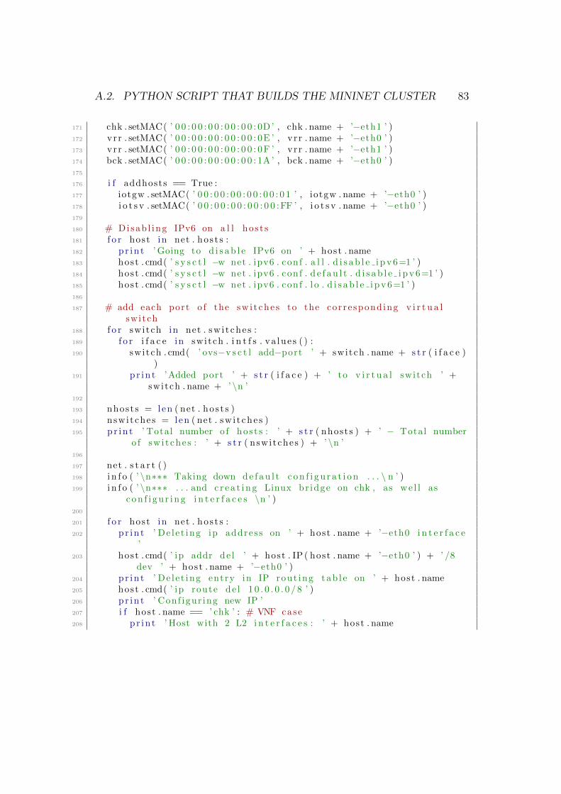
A.2. PYTHON SCRIPT THAT BUILDS THE MININET CLUSTER 83
171 chk . setMAC( ’ 0 0 : 0 0 : 0 0 : 0 0 : 0 0 : 0D ’ , chk . name + ’−eth1 ’ )172 vrr . setMAC( ’ 0 0 : 0 0 : 0 0 : 0 0 : 0 0 : 0E ’ , vr r . name + ’−eth0 ’ )173 vrr . setMAC( ’ 0 0 : 0 0 : 0 0 : 0 0 : 0 0 : 0F ’ , vr r . name + ’−eth1 ’ )174 bck . setMAC( ’ 0 0 : 0 0 : 0 0 : 0 0 : 0 0 : 1A ’ , bck . name + ’−eth0 ’ )175
176 i f addhosts == True :177 iotgw . setMAC( ’ 0 0 : 0 0 : 0 0 : 0 0 : 0 0 : 0 1 ’ , iotgw . name + ’−eth0 ’ )178 i o t s v . setMAC( ’ 0 0 : 0 0 : 0 0 : 0 0 : 0 0 :FF ’ , i o t s v . name + ’−eth0 ’ )179
180 # Disab l ing IPv6 on a l l hos t s181 f o r host in net . hos t s :182 pr in t ’ Going to d i s ab l e IPv6 on ’ + host . name183 host . cmd( ’ s y s c t l −w net . ipv6 . conf . a l l . d i s a b l e i p v 6=1 ’ )184 host . cmd( ’ s y s c t l −w net . ipv6 . conf . d e f au l t . d i s a b l e i p v 6=1 ’ )185 host . cmd( ’ s y s c t l −w net . ipv6 . conf . l o . d i s a b l e i p v 6=1 ’ )186
187 # add each port o f the sw i t che s to the cor respond ing v i r t u a lswitch
188 f o r switch in net . sw i t che s :189 f o r i f a c e in switch . i n t f s . va lue s ( ) :190 switch . cmd( ’ ovs−v s c t l add−port ’ + switch . name + s t r ( i f a c e )
)191 pr in t ’Added port ’ + s t r ( i f a c e ) + ’ to v i r t u a l switch ’ +
switch . name + ’ \n ’192
193 nhosts = len ( net . hos t s )194 nswitches = len ( net . sw i t che s )195 pr in t ’ Total number o f hos t s : ’ + s t r ( nhosts ) + ’ − Total number
o f sw i t che s : ’ + s t r ( nswitches ) + ’ \n ’196
197 net . s t a r t ( )198 i n f o ( ’ \n∗∗∗ Taking down de f au l t c on f i gu r a t i on . . . \ n ’ )199 i n f o ( ’ \n∗∗∗ . . . and c r e a t i n g Linux br idge on chk , as we l l as
c on f i gu r i n g i n t e r f a c e s \n ’ )200
201 f o r host in net . hos t s :202 pr in t ’ De l e t ing ip address on ’ + host . name + ’−eth0 i n t e r f a c e
’203 host . cmd( ’ ip addr de l ’ + host . IP ( host . name + ’−eth0 ’ ) + ’ /8
dev ’ + host . name + ’−eth0 ’ )204 pr in t ’ De l e t ing entry in IP rout ing tab l e on ’ + host . name205 host . cmd( ’ ip route de l 1 0 . 0 . 0 . 0 / 8 ’ )206 pr in t ’ Conf igur ing new IP ’207 i f host . name == ’ chk ’ : # VNF case208 pr in t ’ Host with 2 L2 i n t e r f a c e s : ’ + host . name

84 APPENDIX A. ADDITIONAL NOTES, AND CODE
209 host . cmd( ’ b r c t l addbr br− ’ + host . name)210 host . cmd( ’ b r c t l add i f br− ’ + host . name + ’ ’ + host . name + ’
−eth0 ’ )211 host . cmd( ’ b r c t l add i f br− ’ + host . name + ’ ’ + host . name + ’
−eth1 ’ )212 host . cmd( ’ ip addr add 192 .168 . 107 . 3/24 dev br− ’ + host . name)213 host . cmd( ’ ip l i n k s e t br− ’ + host . name + ’ up ’ )214 pr in t ’LB con f i gu r ed ! ’215 host . cmd( ’ s y s c t l −w net . ipv4 . ip fo rward=1 ’ )216 pr in t ’ IP Forwarding enabled ! ’217 host . cmd( ’ ip l i n k s e t dev ’ + host . name + ’−eth0 mtu 1400 ’ )218 host . cmd( ’ ip l i n k s e t dev ’ + host . name + ’−eth1 mtu 1400 ’ )219 pr in t ’MTU con f i gu r ed on each i n t e r f a c e o f ’ + host . name220 host . cmd( ’ tc qd i s c de l dev chk−eth1 root ’ )221 # introduce a random delay , un i formely d i s t r i b u t e d between
25ms and 35ms222 # and each random sample i s 30% co r r e l a t e d with the prev ious
one223 host . cmd( ’ tc qd i s c add dev chk−eth1 root netem delay 30ms 5
ms 30% ’ )224 pr in t ’ tc s t a r t ed on ’ + host . name225 e l i f host . name == ’ v r l ’ or host . name == ’ vrr ’ :226 i f host . name == ’ v r l ’ :227 host . se t IP ( ’ 1 72 . 1 6 . 1 . 2 54 ’ , 24 , ’ vr l−eth0 ’ )228 host . se t IP ( ’ 192 . 168 . 107 . 1 ’ , 24 , ’ vr l−eth1 ’ )229 pr in t ’ I n t e r f a c e s o f ’ + host . name + ’ have been
con f i gu r ed ! ’230 host . cmd( ’ ip l i n k s e t dev vr l−eth0 mtu 1400 ’ )231 host . cmd( ’ ip l i n k s e t dev vr l−eth1 mtu 1400 ’ )232 pr in t ’MTU con f i gu r ed on each i n t e r f a c e o f ’ + host . name233 e l i f host . name == ’ vrr ’ :234 host . se t IP ( ’ 1 72 . 1 6 . 2 . 2 54 ’ , 24 , ’ vrr−eth0 ’ )235 host . se t IP ( ’ 192 . 168 . 107 . 2 ’ , 24 , ’ vrr−eth1 ’ )236 pr in t ’ I n t e r f a c e s o f ’ + host . name + ’ have been
con f i gu r ed ! ’237 host . cmd( ’ ip l i n k s e t dev vrr−eth0 mtu 1400 ’ )238 host . cmd( ’ ip l i n k s e t dev vrr−eth1 mtu 1400 ’ )239 pr in t ’MTU con f i gu r ed on each i n t e r f a c e o f ’ + host . name240 host . cmd( ’ s y s c t l −w net . ipv4 . ip fo rward=1 ’ )241 pr in t ’ IP Forwarding enabled on ’ + host . name242 e l i f host . name == ’ bck ’ : # BACKUP HOST case243 host . se t IP ( ’ 192 . 168 . 107 . 4 ’ , 24 , ’ bck−eth0 ’ )244 host . cmd( ’ ip l i n k s e t dev bck−eth0 mtu 1400 ’ )245 pr in t ’ IP and MTU con f i gu r ed on ’ + host . name246

A.2. PYTHON SCRIPT THAT BUILDS THE MININET CLUSTER 85
247 pr in t ’ \n ’248
249 # Conf igure rout ing t ab l e s on the v i r t u a l r ou t e r s250 f o r host in net . hos t s :251 i f host . name == ’ v r l ’ :252 host . cmd( ’ route add −net 1 7 2 . 1 6 . 2 . 0 netmask 255 . 255 . 255 . 0 gw
192 . 168 . 107 . 2 ’ )253 host . cmd( ’ route add −net 192 . 1 68 . 1 0 . 0 netmask 255 . 255 . 255 . 0
gw 172 . 1 6 . 1 . 2 53 ’ )254 e l i f host . name == ’ vrr ’ :255 host . cmd( ’ route add −net 1 7 2 . 1 6 . 1 . 0 netmask 255 . 255 . 255 . 0 gw
192 . 168 . 107 . 1 ’ )256 host . cmd( ’ route add −net 192 . 1 68 . 1 0 . 0 netmask 255 . 255 . 255 . 0
gw 192 . 168 . 107 . 1 ’ )257
258 # Conf igur ing debug hos t s259 i f addhosts == True :260 f o r host in net . hos t s :261 i f host . name == ’ iotgw ’ :262 host . se t IP ( ’ 1 7 2 . 1 6 . 1 . 1 0 ’ , 24 , ’ iotgw−eth0 ’ )263 host . cmd( ’ ip l i n k s e t dev iotgw−eth0 mtu 1400 ’ )264 host . cmd( ’ route add −net 192 . 168 . 107 . 0 netmask
255 . 255 . 255 . 0 gw 172 . 1 6 . 1 . 2 54 ’ )265 host . cmd( ’ route add −net 1 7 2 . 1 6 . 2 . 0 netmask 255 . 255 . 255 . 0
gw 172 . 1 6 . 1 . 2 54 ’ )266 e l i f host . name == ’ i o t s v ’ :267 host . se t IP ( ’ 1 7 2 . 1 6 . 2 . 1 0 ’ , 24 , ’ i o t sv−eth0 ’ )268 host . cmd( ’ ip l i n k s e t dev io t sv−eth0 mtu 1400 ’ )269 host . cmd( ’ route add −net 192 . 168 . 107 . 0 netmask
255 . 255 . 255 . 0 gw 172 . 1 6 . 2 . 2 54 ’ )270 host . cmd( ’ route add −net 1 7 2 . 1 6 . 1 . 0 netmask 255 . 255 . 255 . 0
gw 172 . 1 6 . 2 . 2 54 ’ )271
272 f o r switch in net . sw i t che s :273 i f switch . name == ’ s2 ’ :274 # ARP storm avoidance r u l e s on the switch with 2 por t s
connected to the same host275 # ATTENTION: the f i e l d d l type cannot be s p e c i f i e d as a
s t r i ng , but i t must be s p e c i f i e d as in the f o l l ow i ngcommand :
276 switch . cmd( ’ ovs−o f c t l add−f l ow ’ + switch . name + ’ i n po r t=2, d l type=0x0806 , d l d s t=FF:FF:FF:FF:FF:FF, a c t i on s=drop ’ )# ARP −> EthType 0x0806
277 switch . cmd( ’ ovs−o f c t l add−f l ow ’ + switch . name + ’ i n po r t=3, d l type=0x0806 , d l d s t=FF:FF:FF:FF:FF:FF, a c t i on s=drop ’ )

86 APPENDIX A. ADDITIONAL NOTES, AND CODE
278 e l s e :279 #switch . cmd( ’ ovs−o f c t l add−f l ow ’ + switch . name + ’ p r i o r i t y
=1, d l type=0x0806 , a c t i on s=normal ’ )280 # br idge the two ” ex t e rna l ” sw i t che s s6 and s7 to the
network i n t e r f a c e s o f the VM iot−mininet281 i f b r i d g ephy s i c a l == True :282 i f switch . name == ’ s6 ’ :283 pr in t ’ Br idg ing ’ + switch . name + ’ with i n t e r f a c e eth1
o f VM iot−mininet ’284 switch . cmd( ’ ovs−v s c t l add−port ’ + switch . name + ’ eth1 ’
)285 e l i f switch . name == ’ s7 ’ :286 pr in t ’ Br idg ing ’ + switch . name + ’ with i n t e r f a c e eth2
o f VM iot−mininet ’287 switch . cmd( ’ ovs−v s c t l add−port ’ + switch . name + ’ eth2 ’
)288
289 # Set the c o n t r o l l e r f o r the sw i t che s290 f o r switch in net . sw i t che s :291 switch . cmd( ’ ovs−v s c t l set−c o n t r o l l e r ’ + switch . name + ’ tcp :
’ + c o n t r o l l e r i p a d d r e s s + ’ : ’ + c o n t r o l l e r t c p p o r t ) #ForONOS connect ion
292 i n f o ( ’ \n∗∗∗ Waiting f o r switch to connect to c o n t r o l l e r ’ )293 whi le ’ i s c onne c t ed ’ not in quietRun ( ’ ovs−v s c t l show ’ ) :294 s l e e p (1 )295 i n f o ( ’ . ’ )296 i n f o ( ’ \n ’ )297
298 i f debug == True :299 pr in t ’ ∗∗∗∗ DEBUG ACTIVE ∗∗∗∗ ’300 i n f o ( ’ \n∗∗∗ INFO ABOUT HOSTS \n ’ )301 f o r host in net . hos t s :302 host . cmdPrint ( ’ i f c o n f i g ’ )303 host . cmdPrint ( ’ route −n ’ )304 host . cmdPrint ( ’ cat /proc / sys /net / ipv4 / ip fo rward ’ )305 i f host . name == ’ chk ’ :306 host . cmdPrint ( ’ t c −s qd i s c ’ )307
308 i n f o ( ’ \n∗∗∗ INFO ABOUT SWITCHES \n ’ )309 count = 1310 f o r switch in net . sw i t che s :311 switch . cmdPrint ( ’ ovs−o f c t l dump−f l ows ’ + switch . name)312 switch . cmdPrint ( ’ ovs−o f c t l show ’ + switch . name)313 i f count == nswitches :314 pr in t ( ’ L i s t o f sw i t che s : \n ’ )

A.3. PHP SCRIPT IMPLEMENTING THE POST HANDLER 87
315 switch . cmdPrint ( ’ ovs−v s c t l show ’ )316 count = count + 1317
318 arpingone ( net )319
320 i n f o ( ’ . . . running CLI ∗∗∗\n ’ )321 CLI( net )322 i n f o ( ’ \n ’ )323 i n f o ( ’ . . . s topping Network and c l e an ing up ∗∗∗\n ’ )324 net . stop ( )325 os . system ( ’ sudo mn −c ’ )326
327 #Main328 i f name == ’ ma in ’ :329 setLogLeve l ( ’ i n f o ’ )330 startNetwork ( )
Listing A.1: Python script that builds the Mininet cluster
A.3 PHP script implementing the POST han-
dler
1 <?php2 f unc t i on i s J son ( $ s t r i n g ) {3 j s on decode ( $ s t r i n g ) ;4 re turn ( j s o n l a s t e r r o r ( ) == JSON ERROR NONE) ;5 }6 // Make sure that i t i s a POST reques t .7 i f ( strcasecmp ($ SERVER[ ’REQUESTMETHOD’ ] , ’POST ’ ) != 0) {8 echo ”Request method must be POST!\n” ;9 throw new Exception ( ’ Request method must be POST! ’ ) ;
10 }11 // Make sure that the content type o f the POST reques t has been
s e t to app l i c a t i o n / j son12 $contentType = i s s e t ($ SERVER[ ”CONTENTTYPE” ] ) ? trim ($ SERVER[ ”
CONTENTTYPE” ] ) : ’ ’ ;13 i f ( strcasecmp ( $contentType , ’ a pp l i c a t i o n / j son ’ ) != 0) {14 echo ”Content type must be : app l i c a t i o n / j son \n” ;15 throw new Exception ( ’ Content type must be : app l i c a t i o n / j son ’ ) ;16 }17 // Receive the RAW post data .18 $content = trim ( f i l e g e t c o n t e n t s ( ”php :// input ” ) ) ;

88 APPENDIX A. ADDITIONAL NOTES, AND CODE
19 // Check i f content i s v a l i d JSON20 i f ( ! i s J s on ( $content ) ) {21 echo ”Received content conta ined i n v a l i d JSON!\n” ;22 echo ’ | ’ . $content . ’ | ’ ;23 throw new Exception ( ’ Received content conta ined i n v a l i d JSON! ’
) ;24 } e l s e {25 echo ”Received va l i d JSON. Adding i t s content to database .\n” ;26 }27 // Remove newl ines and c a r r i a g e r e tu rn s28 p r e g r ep l a c e ( ”/\ r | \n/” , ”” , $content ) ;29 // Def ine the name o f the database f i l e30 $ d b f i l e = ’ database . j son ’ ;31 // Read the cur rent database32 $ fh = fopen ( $db f i l e , ’ r+’ ) or d i e ( ”Can ’ t open f i l e ” . $ d b f i l e ) ;33 $ s t a t = f s t a t ( $ fh ) ;34 f t r unca t e ( $fh , $ s t a t [ ’ s i z e ’ ]−2) ;35 f c l o s e ( $ fh ) ;36 // i f i t i s only i n i t i a l i z e d but s t i l l empty , j u s t append the new
data37 i f ( $ s t a t [ ’ s i z e ’ ] == s t r l e n ( ’ {”data ” : [ ] } ’ ) ) {38 $data = $content . ’ ]} ’ ;39 }40 // i f i t a l r eady conta in s some data , append a comma then the new
data41 e l s e {42 $data = ’ , ’ . $content . ’ ]} ’ ;43 }44 // wr i t e the new database to the same f i l e45 f i l e p u t c o n t e n t s ( $db f i l e , $data , FILE APPEND | LOCK EX) ;46 ?>
Listing A.2: PHP script implementing the POST handler

Bibliography
[1] F. Callegati, W. Cerroni, and C. Contoli. “Virtual Network Performancein OpenStack platform for Network Function Virtualization”. In: Journalof Electrical and Computer Engineering (2016).
[2] W. Cerroni, C. Buratti, S. Cerboni, G. Davoli, C. Contoli, F. Foresta,F. Callegati, and R. Verdone. “Intent-Based Management and Orches-tration of Heterogeneous OpenFlow/IoT SDN Domains”. In: NetSoft17.2017.
[3] F. Foresta. “Composizione Dinamica di Funzioni di Rete Virtuali in Am-biente Cloud”. 2015.
[4] NFV, Cloud and SDN. url: https://networkbuilders.intel.com/docs/Genband_nfv_whitepaper.pdf.
[5] F. Callegati, W. Cerroni, C. Contoli, R. Cardone, M. Nocentini, andA. Manzalini. “SDN for dynamic NFV deployment”. In: IEEE Com-munications Magazine 54.10 (2016), pp. 89–95. issn: 0163-6804. doi:10.1109/MCOM.2016.7588275.
[6] Intent NBI - Definition and Principles. Tech. Rec. The Open NetworkingFoundation (ONF), 2016. url: https://www.opennetworking.org/sdn-resources/technical-library.
[7] F. Hu, Q. Hao, and K. Bao. “A Survey on Software-Defined Networkand OpenFlow: From Concept to Implementation”. In: IEEE Communi-cations Surveys Tutorials 16.4 (2014), pp. 2181–2206. issn: 1553-877X.doi: 10.1109/COMST.2014.2326417.
[8] Open Networking Foundation. “Software-Defined Networking: The NewNorm for Networks”. In: (2012).
89

90 BIBLIOGRAPHY
[9] SDN Architecture Overview. Tech. Rec. The Open Networking Founda-tion (ONF), 2013. url: https://www.opennetworking.org/images/stories/downloads/sdn-resources/technical-reports/SDN-architecture-
overview-1.0.pdf.
[10] F. Callegati, W. Cerroni, C. Contoli, and F. Foresta. “Performance ofIntent-based Virtualized Network Infrastructure Management”. 2017.
[11] N. McKeown, T. Anderson, H. Balakrishnan, G. Parulkar, L. Peterson,J. Rexford, S. Shenker, and J. Turner. “OpenFlow: Enabling Innovationin Campus Networks”. In: White paper. 2008.
[12] S. Seetharaman. OpenFlow/SDN tutorial. OFC/NFOEC. 2012. url: http://www.slideshare.net/openflow/openflow-tutorial.
[13] OpenFlow. url: https://www.opennetworking.org/sdn-resources/openflow.
[14] Q. Hassan. “Demistifying Cloud Computing”. In: The Journal of DefenseSoftware Engineering (2011).
[15] R. Mijumbi, J. Serrat, J. Gorricho, N. Bouten, F. De Turck, and R.Boutaba. “Network Function Virtualization: State-of-the-Art and Re-search Challenges”. In: IEEE Communications Surveys and Tutorials,Vol 18, No. 1 (2016).
[16] Network Functions Virtualisation (NFV); Architectural Framework. TheEuropean Telecommunications Standards Institute (ETSI). 2013. url:http://www.etsi.org/technologies-clusters/technologies/nfv.
[17] Network Functions Virtualisation (NFV); Management and Orchestra-tion. The European Telecommunications Standards Institute (ETSI),2014. url: http://www.etsi.org/technologies-clusters/technologies/nfv.
[18] ONOS: Open Network Operating System. url: http://onosproject.org.
[19] ONOS Wiki. url: https://wiki.onosproject.org/.
[20] Mininet: An Instant Virtual Network on your Laptop. url: http://
mininet.org.
[21] OpenStack: Open Source Cloud Computing Software. url: https://
www.openstack.org.

BIBLIOGRAPHY 91
[22] P. Quinn and U. Elzur. “Network Service Header”. In: IETF Internet-Draft draft-ietf-sfc-nsh-10 (2016).
[23] S. Cerboni. Software Defined Networking for the Internet of Things. 2016.
[24] Oracle VirtualBox. url: https://www.virtualbox.org/.
[25] Ubuntu 14.04. url: http://releases.ubuntu.com/14.04/.
[26] IntelliJ IDEA. url: https://wiki.onosproject.org/display/ONOS/IDE+Setup.
[27] Xming. url: http://www.straightrunning.com/XmingNotes/.
[28] Virtual Machine Manager. url: https://virt-manager.org/.
[29] Mininet Python API Documentation. url: http://mininet.org/api/index.html.
[30] Ubuntu 16.04. url: http://releases.ubuntu.com/16.04/.

92 BIBLIOGRAPHY

Acknowledgments
This Master Thesis contains the results of my work in the last few months,but it can only serve as a symbol of the true, most important achievement ofthe last period for me: I got the chance to meet, get to know, and work withsome of the most kind, humane, and professionally skilled people I have evermet.
First and foremost, I would like to thank Prof. Walter Cerroni, for hisinvaluable representation of the values I have mentioned above. He gave methe opportunity to spend my Master Thesis period with him and the researchgroup he works into, and it has been an opportunity I will always be glad Ihave had.
Without loss of importance, I also wish to thank Dr. Chiara Contoli,on whose work I have based mine, and who has always been available forconfrontation and help, starting when she still was thousands of kilometersaway for her Ph.D period abroad.
Third, but equally important (you know my affection for number 3, so youcan understand that this is a very honorable position for me to put you in),I would like to thank my captain Francesco Foresta, who literally welcomedme with a hug on my first day in Net2Lab, and kickstarted my activities, bysharing with me his vast practical knowledge on how to configure stuff, how torun it, where to eat the best kebab and where to buy the best Chinese trinketsonline. Joking aside, there is hardly anything I can say about him that wouldencompass the entirety of what he shared with me throughout these past fewmonths. I will try doing it with a hug.
I wish to thank Prof. Carla Raffaelli, as well as Prof. Franco Callegati, bothof whom have always made me feel welcome in Net2Lab and more generallyin the research group they share.
93

94 BIBLIOGRAPHY
I also wish to thank Prof. Chiara Buratti, as well as my fellow colleagueand friend Simone Cerboni, for their tireless work on the IoT part, and theiravailability to a fruitful collaboration on the activities presented in this thesis.
I would like to dearly thank Federico, Andrea and Bahare, whom I shared somany moments of fun with, and played a key role in my decision of remainingto work there after my graduation. Thank you guys, it has been my honorand privilege to work alongside all of you.
Special thanks go to Silvia, who started from being a great university col-league and became a dear every-day friend. Friendship can rise above neigh-borhood battles, and we have the power to prove it. There is much more tosay about her, too, but I think I will resolve in giving her a hug as well.
I would also like to thank il mio caro collega Shaham, the man with thecoolest mustache ever, who was the first one to show me that Iranian peopleare much more similar to Italians than we think, and gave me crash courses inthe Persian language. I am very glad that the two of us graduate on the sameday. Khasteh nabashi, dooste man.
My thanks also go to my fellow course mates and friends Giammarco (“Roc-cia”, “Bomber”, “Troppo Grosso”) and Matteo (“Maestro”, “Mitico”), whoprovided these last two years with invaluable rumagnol spontaneity, thanksto which I now no longer hang out with people, but I vado oltre and facciobagarre with them.
I also want thank Bob, my first real English teacher, who honored me withhis friendship long ago, and offered his opinion on this thesis to me, which hasbeen my first major work written in English. A big hug to Gabrielle, too, foralways being so smiling. Cheers ’n’ beers!
Best for last, I wish to thank my family, who has never left me alone andhas always cheered for me.
Mamma Terry, Babbo Gianni, Nonno Marcello, Zia Lalla: grazie, vi vogliotantissimo bene.
E Teresa, ti amo.
Casalecchio di Reno, Bologna - 8 March 2017