INTENSIV T echnical brochure · 3.2 Dedusting 3.3 Washing 3.4 Drying 4 Applications 5...
16
T e c h n i c a l b r o c h u r e Function and construction features CIP – Cleaning in Place Filter INTENSIV FILTER Mighty solutions for tiny particles.
Transcript of INTENSIV T echnical brochure · 3.2 Dedusting 3.3 Washing 3.4 Drying 4 Applications 5...

Te
ch
ni
ca
l
br
oc
hu
re
Function and construction featuresCIP – Cleaning in Place Filter
INTENSIVFILTER
Mighty solutions for tiny particles.

2
CIP – Cleaning in PlaceFunction and construction features
1 Introduction
2 Installation description
3 Function description3.1 Filtering3.2 Dedusting3.3 Washing3.4 Drying
4 Applications
5 Constructional layout5.1 Housing5.2 Fire and explosion protection5.3 Filter bags and supporting cages
6 Set-up and function of the dedusting system
7 Compressed air supply
8 Discharge apparatus
9 Standards, Certificates
10 Type designation codes
Table of contents

CIP filters (Cleaning-In-Place) are special product filters for industrial applications. They are used everywhere where frequent product changes, product ageing or product contamination caused by germ and bacterial for-mation necessitate a cleaning of the filter. The CIP appa-ratus makes it possible to clean the filter of all product residues which can be dissolved through the use of washing fluids.
The filter is therefore primarily used in the food and chem-ical industries, but can however also be utilised in many other branches of industry. The filter construction is suit-able in practice for a wide range of air volume flows.
This document will provide you with an introduction to the characteristics and data of our CIP filters. Also included are descriptions of installations and functions, typical applications, information concerning constructional lay-out and special characteristics, in addition to information regarding the standards and directives which must be observed.
The advantages to use a CIP filter are manifold:Recovery of powder losses up to 3% in case there are only cyclonesRecovery of powder as QC1 (Quality Standard 1) because there is no contamination of powders (i.e. milk powders) in CIP filtersEnergy reduction up to 30% by replacing cyclones by CIP filtersSubstantial saving of “space” in case of a new spray drier plantOperator friendly spray drier plant (i.e. no clogging of cyclones)Suitable for hygroscopic powders and powders with high free fat content
Image 1 Diagram of the spray dryer with CIP filter, using powdered milk production as an example
1 Spray dryer2 CIP filter3 External fluidised bed
Products are produced in powder form from fluid products by the evaporation of residual water in spray dryers.
During this process, the powder is conveyed from the spray drier into the fluid bed for secondary drying and cooling. The exhaust air is “dedusted” in a downstream CIP filter.
1 Introduction 2 Installation description
1
1
1
22
33
3

Image 2 CIP filter1 Clean gas chamber2 Filter bag3 Raw gas chamber
The CIP filters are designed for a dry filtration process and cyclical washing.
This means that the product residues are washed out in a washing process “on site” and that the filter is then set up for the next filtration process after drying.
The work sequence of the filter can be subdivided into four processes:
3.1 Filtering
3.2 Dedusting
3.3 Washing
3.4 Drying
3.1 Filtering
Image 3 Filtering1 Product-gas mixture (raw gas)2 Filter bag3 Supporting cage4 Clean gas
The gas mixture loaded with the product flows inward from the outside through the filter bags. The product accumulates in filter cake form on the sur-face of the filter bags and the gas is able to exit the filter through the clean gas chamber. As a result of the pres-sure differential between the outside and the inside of the filter bag, it positions itself in a star-formation around the supporting cage.
Surface filtration is employed with the filter bags having a special surface treatment for CIP filters.
3.2 DedustingThe CIP filter is equipped with a fully automatic dedusting system. The filter bags are dedusted through the pat-ented two-stage Coanda injector system by means of a compressed air pulse. The dedusting gas flow is guided thereby through the inlet nozzles into the filter bags, where it causes the reversal of the filtration flow into the dedusting flow.
As a result of the pressure change, the filter bag that was previously pressed against the supporting cage in a star shape is now “blown up” to form a circle. The product adhering to the outer side of the filter bag is loosened by the mechanical movement and the backwashing of the dedusting gases and is returned to the discharge base located underneath.
3 Function description
23
1
1 2
3
4
4

Image 4 Dedusting1 Clean gas chamber2 Coanda injector3 Inlet nozzles4 Dedusting gases5 Filter bag6 Supporting cage7 Raw gas chamber
3.3 Washing
Image 5 Washing1 Washing nozzle groups2 Washing fluid3 Filter bags Various reasons can exist to make an intensive cleaning of the filter necessary:
The dry filtration has been completed, e.g. because of downtimes or similar.Hygiene technology considerations may come into play.A product change is being carried out.
To wash the filter, the washing nozzle groups aligned in the filter directly spray the sides of the housing and the filter bags intensively with washing fluid. This flushes out any sticking product residues. Depending on the type of product and hygienic require-ments, further options are also available besides the cleaning procedure with water:
DisinfectionNeutralisationWashing with other auxiliary agents, e.g. protein sol-vents and similar
1
11
2
3
4
5
6
3
7
77
1
2
3
1
5

3.4 Drying
Image 6 Drying1 Hot air flow
The CIP pipe system is blown empty with compressed air after the cleaning procedure. Afterwards, the filter and the filter bags are dried with the still hot air flow from the spray dryer exhaust.
The CIP filter is then once again completely regenerated for the production of products in powder form.
An important area of application which has been included because of the intensive cleaning is the production of hygienically perfect products such as food or pharmaceu-tical products.
The use of cyclones can be dispensed with the utilisation of our CIP filter. Short payback periods are possible, thanks to the high level of product recovery in conjunction with energy savings.
Typical areas in which the CIP filter technology is utilised include the manufacture of
Foodstuffs such asMilk powders, whey powders, milk protein, whey protein concentrates, permeate powders and fat filled powders with high fat contentBaby food powderYeast powderLactose and maltodextrinsDietetic products such as inulin powderMeat protein extracts
Pharmaceutical products such asBlood plasma powderEnzymes powderSoybean protein powder
Chemical products such asOrganic and inorganic raw materialsDyes
1
4 Applications
6

5.1 Housing
Image 7 Filter housing
1 Housing2 Clean gas chamber3 Clean gas outlet4 Filter plate5 Raw gas inlet6 Raw gas baffle plate 7 Filter bags8 Raw gas chamber 9 Filter cone10 Product discharge
The CIP filter is a round filter with a cylindrical housing (Image 7) which narrows to form a cone in its lower part.
The housing is made of stainless steel 1.4301 ((X5CrNi18-10), AISI 304 (V2A)) and is designed to be pressure shock resistant (cf. explosion protection).
Various maintenance openings and installation and transport devices are fitted in and on the housing.
The clean gas chamber with the clean gas outlet is located in the upper part of the filter.
The filter plate separates the clean gas chamber from the raw gas chamber in the upper part of the filter.
The filter bags are aligned in the raw gas chamber. Behind the raw gas inlet is located a raw gas baffle plate which provides optimal channelling of the product flow into the raw gas chamber and prevents direct flow in the direction of the filter bags.
The heated filter cone with the product discharge is located on the lower part of the housing (Image 8). This is designed to have double walls and is heated with preheated air.
Image 8 Filter cone with product discharge1 Direction of product movement2 Flow of air on the screen discharge base3 Product discharge4 Product5 Reverse aeration cone
The product discharge is implemented using a fluid bed discharge base with openings facing downward.
5 Constructional layout
1
2
3
4
5
6
7
8
9
10
7

5.2 Fire and explosion protection
Fire and explosion protection measures are required when dedusting combustible dusts. The fire protection is implemented with appropriate configurations of special extinguishing nozzles. Fires can be detected with CO, Infrared or temperature sensors.
If an operator cannot avoid potential ignition sources (e.g. intake of hot particles, sparks, ember pockets) or if the dust has a high self-ignition potential, then CIP filters should be equipped with structural explosion protection measures.
A distinction is made here between explosion suppres-sion and explosion pressure discharge. The filter housing is designed in both cases for a reduced explosion pres-sure (e.g. 0.7 bar or 1 bar).
In the case of explosion suppression, a special extin-guishing agent is immediately introduced into the filter at the first sign of an explosion, thus suppressing the explo-sion at the earliest possible stage. The signal for the acti-vation of the extinguishing agent container is transmitted via highly sensitive pressure sensors or/and Infrared detectors.
Image 9 Explosion suppression1 Extinguishing agent block2 Extinguishing agent container3 Pressure sensor
In the case of explosion pressure discharge, the explo-sion is dissipated in a controlled manner through the use of burst discs. In order to avoid any blockage of the discharge openings by filter elements in the event of an explosion, Intensiv-Filter has, together with DEKRA Exam GmbH, developed an effective restraint system and thus enhanced the safety of the CIP filter even further.
Image 10 Explosion pressure discharge1 Clean gas area, no explosion spread (dust concen-
tration under explosion limit)2 Burst discs3 Spread of pressure and flame (safety zone surround-
ing pressure relief devices)4 Spread of pressure and flame
3
2
1 4
1
3
2
8

As a basic rule, decoupling measures are to be set up in the event of the integration of a structurally shielded CIP filter in an overall installation in order to avoid the trans-mission of an explosion between containers, appliances and machinery. Secure decoupling measures include, for example, extinguishing agent blocks, quick-closure slides and Ventex valves.
Image 11 Explosion protection1 Quick-closure slides2 Ventex valve3 Pressure sensor
Intensiv-Filter supports the operator with the develop-ment of the explosion protection concept for compliance with the Atex Directives (94/9/EG, 1999/92/EG) as well as with additional standards and directives (VDI 2263, AD Directive, among others) and applies its extensive expertise in the project planning.
5.3 Filter bags and supporting cages
Filter bags are characterised by the following data:Diameter “D”Length “L”Material qualitySpecial design details
The quality of the material is of decisive importance for the functioning of the filter and is handled in accordance with the respective application. The decisive factors here are:
The operating data of the installationType of product, raw gas composition and particle distribution of the productProcess engineering of the installation to be dedustedPrecipitation effectiveness/emission limit values
Image 12 Filter bags in CIP design The filter bags used have the “surface filtration” function and have been processed accordingly.
The use of original bags from Intensiv-Filter ensures that there will be no contamination through fibre formation/fibre abrasion during product recovery.
The supporting cages stabilise the filtration media and are utilised with the filter bags in the filter plate. They thus separate the raw gas zone from the clean gas zone.
1
2
3
9

Depending on the length of the bags, the supporting cage is made up of one or more parts. The one-piece version will be implemented where there are sufficient disman-tling heights.Disconnected supporting cages from Intensiv-Filter can be readily connected with one another.
Multipart supporting cages are used in cases of space limitations and long filter bags.
The end rings for connecting the inlet nozzles and the intermediate rings are equipped with a joint.
Original supporting cages from Intensiv-Filter are cali-brated precisely to the filter bags and ensure that the filter bags have as long a service life as possible.
Image 13 Supporting cages1 Supporting cage, two-piece2 Supporting cage, one-piece3 Separated end rings4 Supporting cage upper part5 Supporting cage lower part6 Supporting cage bottom7 Intermediate ring
The filter bags can be readily replaced during mainte-nance work.
The filter bags are hung in the filter plate (Image 14).
Image 14 Positioning of the filter bag
The separated supporting cages are connected by an intermediate ring with the aid of the assembly lever (Image 15).
Image 15 Connecting divided supporting cages
21
3
4
5
7
3
6
10

The supporting cages are inserted into the filter bag up to the inlet nozzle (Image 16).
Image 16 Insertion of a supporting cage
The upper edge of the inlet nozzle lies on the sealing ring of the filter bag and is fixed in place with clamps and fas-tening material (Image 17).
Image 17 Fixation of filter bag and supporting cage
The JetBus dedusting system is used for intelligent con-trol and monitoring of the filter dedusting.
Image 18 Dedusting systemImage 18 shows the filter head with integrated dedusting system. It is comprised of:1 Valve manifold2 Diaphragm valve3 Injector tube4 Inlet nozzle5 Coanda injector
6 Set-up and function of the dedusting system
11

The dedusting system is controlled by a microprocessor and is comprised of the JetBus Controller and 1 to 15 interface modules which are installed in pilot boxes. The controller communicates with the pilot boxes by means of modern bus technology. This considerably reduces the amount of cabling required. JetBus Controller and pilot box are connected solely by means of a supply and a data cable.
Image 19 Valve manifold with diaphragm valves and pilot boxes
Image 20 Dedusting system electrical cabling1 CIP filter2 Terminal box 3 JetBus Controller4 Line for additional functions (malfunction messages)5 Mains line6 Pilot boxThe “intelligent valve module” connected with the bus enables a more precise monitoring and more direct assessment of the dedusting system. This provides the operator with the greatest possible level of safety, because the pilot boxes operated with 24 V technology.
All control parameters can be digitally adjusted:Pulse timeTwo different rest timesNumber of after-running cyclesFunction of a control inputFunction of relay outputs
All valves are switched individually, one after the other, following a pulse sequence optimised for CIP filters. This ensures uniform dedusting of the filter.
Image 21 Diaphragm valve, 2-stage1 Valve closed2 Valve open
The JetBus Controller sends the signal for dedusting to the pilot boxes and onward from there to the dia-phragm valves.
Pressure is reduced in the antechamber of the diaphragm valves. The pressure in the valve manifold opens the valve completely. The dedusting gas flows into the injec-tor tube and from there into the Coanda injectors (see “Dedusting” on page 4).
1
2
3
4
5
6
1
2
12
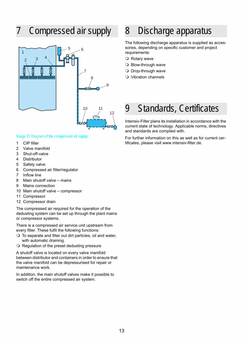
Image 22 Diagram of the compressed air supply1 CIP filter2 Valve manifold3 Shut-off-valve4 Distributor5 Safety valve6 Compressed air filter/regulator7 Inflow line8 Main shutoff valve – mains9 Mains connection10 Main shutoff valve – compressor11 Compressor12 Compressor drain
The compressed air required for the operation of the dedusting system can be set up through the plant mains or compressor systems.
There is a compressed air service unit upstream from every filter. These fulfil the following functions:
To separate and filter out dirt particles, oil and water, with automatic draining.Regulation of the preset dedusting pressure
A shutoff valve is located on every valve manifold between distributor and containers in order to ensure that the valve manifold can be depressurised for repair or maintenance work.
In addition, the main shutoff valves make it possible to switch off the entire compressed air system.
The following discharge apparatus is supplied as acces-sories, depending on specific customer and project requirements:
Rotary waveBlow-through waveDrop-through waveVibration channels
Intensiv-Filter plans its installation in accordance with the current state of technology. Applicable norms, directives and standards are complied with.
For further information on this as well as for current cer-tificates, please visit www.intensiv-filter.de.
7 Compressed air supply
1
2 3 4
5 6
7
8
9
10 11
12
8 Discharge apparatus
9 Standards, Certificates
13

10 Type designation codes
(Example) I F - P J A - R D - x x x - 1 - x x x x x - x - C C S - x
Intensiv-Filter
Series: ProJet allround P J A
Design: Round filter, Standard RType: Filter with discharge base D
Installation size (number of bags per head module):
Number of head modules: 1
Nominal housing height (in mm):
Model: Standard depressurised SPressure shock resistant (Ex) E
Dedusting: Coanda CMode of operation: CIP CModel: Standard S
Bag placement: Standard SCustomer-specific D
14

15

16
TD.08.009 GBIntensiv-Filter GmbH & Co. KG
Voßkuhlstraße 63 42555 Velbert-LangenbergDeutschland / Germany
+49 2052 910-0 +49 2052 910-248if@intensiv-fi lter.de www.intensiv-fi lter.de
Technical modifi cations reserved09.08-500 FD