Intelligent Touch Manager BACnet® Server Gateway...The iTM BACnet® Server gateway has a built-in...
14
Intelligent Touch Manager BACnet® Server Gateway DCM014A51 QUICK USER GUIDE UGUS_DCM014A51_03-17
Transcript of Intelligent Touch Manager BACnet® Server Gateway...The iTM BACnet® Server gateway has a built-in...

Intelligent Touch Manager BACnet® Server Gateway
DCM014A51
QUICK USER GUIDE
UGUS_DCM014A51_03-17

Contents
1. VRV System Overview ............................................................................................................................................. 3 2. Types of Daikin VRV Systems .................................................................................................................................. 3 3. Group Addressing Types for Indoor Units............................................................................................................... 4 4. Typical BACnet® Server Gateway Application ........................................................................................................ 5 5. BACnet® Server Gateway Points List ....................................................................................................................... 6 5.1. iTM System Points List ..................................................................................................................................... 6 5.2. Indoor Unit Points List ..................................................................................................................................... 6 6. Programming Notes ................................................................................................................................................. 9 6.1. iTM Control Logic and The Related BACnet® Points........................................................................................ 9 6.2. Setpoints ......................................................................................................................................................... 9 6.3. Auto-changeover ............................................................................................................................................. 9 6.4. Setpoints Range Limitation ........................................................................................................................... 10 6.5. Schedule ........................................................................................................................................................ 10 6.6. Timed Override .............................................................................................................................................. 10 6.7. Remote Controller Prohibits ......................................................................................................................... 10 6.8. Forced System Shutdown .............................................................................................................................. 10 6.9. Priority Array ................................................................................................................................................. 11 6.10. Restrictions .................................................................................................................................................... 11 7. Summary ................................................................................................................................................................ 13
1. VRV System Overview
DCM014A51 Quick User Guide 3
1. VRV System Overview The Daikin VRV system consists of outdoor units, indoor units, zone controllers, centralized controllers, and BMS Interfaces. The VRV system communicates by using a proprietary protocol, which is communicated on the DIII-Net bus. When a centralized controller or a BMS interface is connected to the DIII-Net bus, a unique group address is required for the unit to be monitored and controlled. The customizable Daikin control system is built around the VRV system, and does not require any advanced field engineering (such as programming) for the control of the VRV system, except for individual indoor unit and controls configurations.
2. Types of Daikin VRV Systems The VRV system can consist of Heat Recovery systems, Heat Pump systems, or a system that is a combination of both. (Refer to iTM BACnet® Server Design Guide – Part 1 for more details.)
1. Heat Recovery systems can provide simultaneous cooling and heating to each indoor unit served by the same outdoor unit with the use of Branch Selector Boxes (BS Box).
2. Heat Pump systems only allow each outdoor unit and its connected indoor units to be in either cooling
or heating at any one time. Multiple Heat Pumps systems can be installed at a site and will operate independently of each other in their own operation mode (Cool, Heat, Fan, Dry, and Auto).
Outdoor Units
Indoor Units
Branch Selector Box
Indoor Units
Outdoor Units
3. Group Addressing Types for Indoor Units
4 Quick User Guide DCM014A51
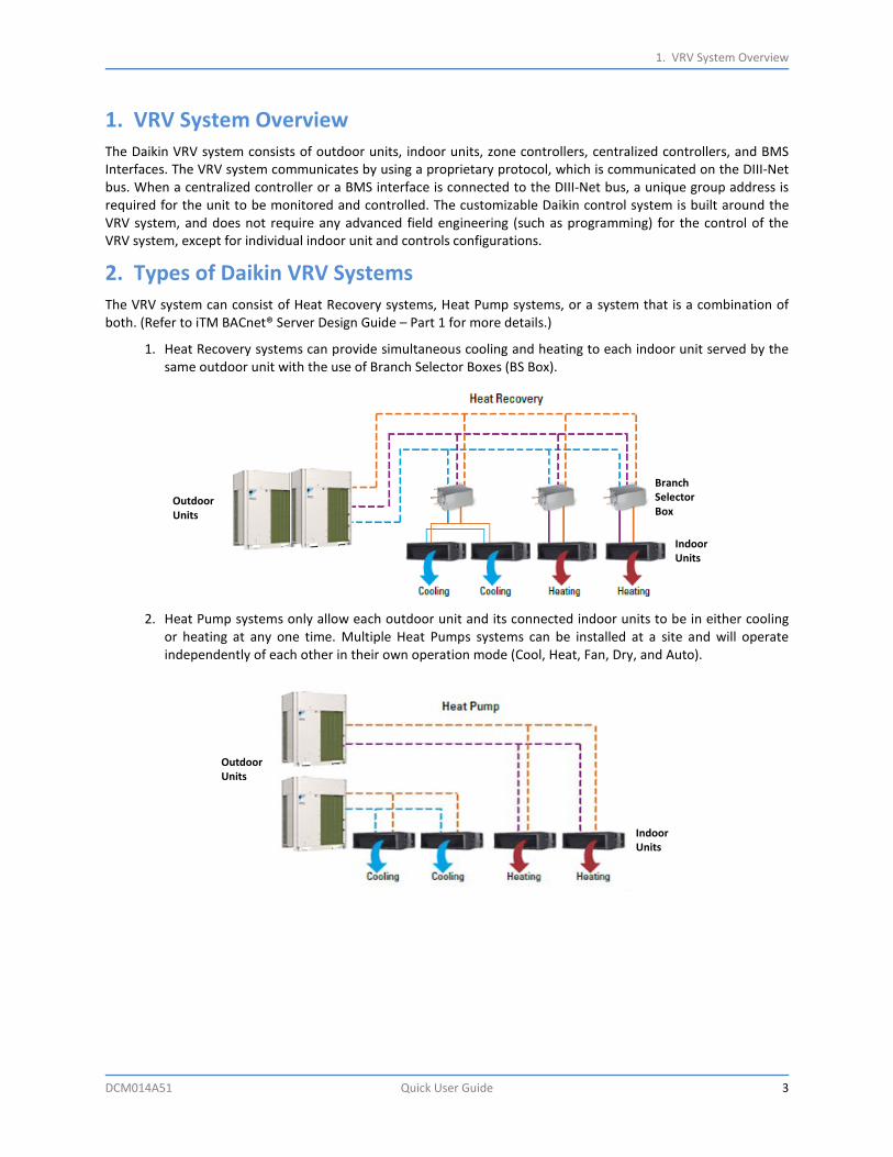
3. Group Addressing Types for Indoor Units A group address is a unique address that assigned manually to an indoor unit or a group of indoor units on the DIII-Net system during the VRV commissioning process. Up to 64 group addresses can be assigned in one DIII-Net system. Group addresses are as follows: 1-00 to 1-15, 2-00 to 2-15, 3-00 to 3-15 and 4-00 to 4-15. A remote control group consists of 1 to 16 indoor units daisy-chained together via P1P2 connections. The unit# is used to identify the indoor unit within a group of indoor units, unit#0 is the indoor unit responsible for receiving commands from the iTM, and relay the data to the other units in the group.
1. A group address assigned to a single indoor unit (typical configuration).
* F1F2 = DIII-Net ** P1P2 = Remote Controller line
2. A group address assigned to a remote controller group.
3. A group address to each indoor unit in a remote controller group.

4. Typical BACnet® Server Gateway Application
DCM014A51 Quick User Guide 5
4. Typical BACnet® Server Gateway Application
1. The iTM BACnet® Server Gateway (DCM014A51) software option provides communication between the VRV system and the BMS. The operation and monitoring of the VRV system through BACnet® communication uses the BACnet®/IP protocol.
2. Up to 128 indoor unit management points (indoor units groups) can be controlled and monitored through the iTM BACnet® Server Gateway.
3. Up to 7 additional DIII-Net communication systems can be added with the optional iTM Plus Adaptors. 4. The iTM BACnet® Server Gateway support change of value (COV). 5. The iTM BACnet® Server Gateway can be registered as a foreign device. 6. The iTM BACnet® Server gateway has a built-in virtual BACnet® router that provides seamless control
logic integration between the iTM and BMS. a. Every indoor unit group address will be visible as BACnet® device on the BACnet® Network. b. Indoor unit name on the iTM will be synced as BACnet® device name. c. Allows ease of programming and graphics replication.

5. BACnet® Server Gateway Points List
6 Quick User Guide DCM014A51
5. BACnet® Server Gateway Points List 5.1 iTM System Points List
The following are iTM system points that link to the iTM's control logic. Each iTM has only one set of system points. Refer to iTM BACnet® Server Design Guide– Part 2 for points description.
Instance No. Object_Name Type
Inactive Active Remarks Text-1 Text-2 Text-3 Text-4 Text-5 Text-6 Text-7
1 Enable iTM Schedule Operation BO Disable Enable
2 Enable iTM
Auto-Changeover Operation
BO Disable Enable
3 Timed Override Minutes MV 30 60 90 120 150 180 4 System Forced Off BO Inactive Active
5.2 Indoor Unit Points List
The following are indoor unit control and monitoring points. Each indoor unit group shall have one set of these points. Refer to iTM BACnet® Server Design Guide– Part 2 for point description.
Instance No. Object_Name Type
Inactive Active Remarks
Text-1 Text-2 Text-3 Text-4 Text-5 Text-6 Text-7 Text-8
1 Occupancy Mode MO Unocc Occ Standby
2 Unit On_Off Status BI Off On
3 Alarm Status BI Normal Alarm Sets error
code in the
4 Operation Mode MV Cool Heat Fan Dry See (1) below.
5 Room Temperature AI *1, *2
6 Occ Cooling Setpoint AV *1, *2
7 Occ Heating Setpoint AV *1, *2
8 Unocc Cooling Setpoint AV *1, *2, *3
9 Unocc Heating Setpoint AV *1, *2, *3
10 Max Cooling Setpoint AV
*1, *2, *4 11 Min Cooling
Setpoint AV
12 Max Heating Setpoint AV
*1, *2, *4 13 Min Heating
Setpoint AV
14 Min Setpoint Differential
AV *1, *2
15 Cooling & Heating Setpoint Tracking
BV Disable Enable
Continued on next page.

5. BACnet® Server Gateway Points List
DCM014A51 Quick User Guide 7
Instance No. Object_Name Type
Inactive Active Remarks
Text-1 Text-2 Text-3 Text-4 Text-5 Text-6 Text-7 Text-8
16 Fan Speed MV Low Reserved Medium Reserved High Reserved Reserved Auto
17 Airflow Direction MV P0 P1 P2 P3 P4 Reserved Reserved P7
18 Timed Override Operation BV Disable Enable
19 Current Unit Operation MI Off Normal Override Setback
20 Remote Controller Prohibit
MV Permit Prohibit Stop Only
21 Remote Controller
Prohibit (Operation Mode)
BV Permit Prohibit
22 Remote Controller
Prohibit (Setpoint)
BV Permit Prohibit
23 Filter Sign Status BI Normal Alarm
24 Filter Sign Reset BV Reset Alarm
25 Indoor Fan Status BI Off On
26 Communication Status BI Normal Alarm
27 Thermo-on Status BI Off On
28 Compressor Status MI Off On Defrost/ Hot Start
29 Aux Heater Status BI Off On
30 Forced Thermo-off BV Disable Enable
31 Indoor Unit Changeover Option BI Not
Available Available
*1: The unit of temperature (Celsius or Fahrenheit) follows the iTM locale (regional settings). *2: The number of valid digits for each object is shown in the table below. If a value entered from BMS has a higher precision than the
number of significant digits of an object, the digits after the significant digits are rounded. (For example, when OccCoolingSetpoint is "75.55" in degrees Fahrenheit, round it to "76".) Regarding values in commands sent from the BMS, the iTM rounds them off to the number of the significant digits. (For example, if the value in a command for OccCoolingSetpoint is "75.55" in degrees Fahrenheit, it is rounded to "76".)

5. BACnet® Server Gateway Points List
8 Quick User Guide DCM014A51
Object Name Number of valid digits
Celsius Fahrenheit
“Room Temperature” One decimal place One decimal place
"Occ Cooling Setpoint" "Occ Heating Setpoint" "Unocc Cooling Setpoint" "Unocc Heating Setpoint" "Max Cooling Setpoint" "Min Cooling Setpoint" "Max Heating Setpoint" "Min Heating Setpoint"
One decimal place Integer
"Min Setpoint Differential (Cooling & Heating)” Integer Integer
*3: When the Out_Of_Service property is TRUE, the setting items (Setback Temperature (Cool/Heat), Min Setpoint Differential (Cooling & Heating) that are mapped to the object are disabled; therefore, a value set on the indoor unit management point remains unchanged even if Present_Value is changed.
*4: The Out_Of_Service property of "Max Cooling Setpoint" and "Min Cooling Setpoint" indicates the upper and lower limit of the Cool Setpoint change along with the Present_Value.
(When the Out_Of_Service property of either one is changed from FALSE → TRUE, the Out_Of_Service property of the other one also changes from FALSE → TRUE)
The "Max Heating Setpoint" and "Min Heating Setpoint" which indicates the upper and lower limit of the Heat Setpoint also behaves in the same way. When the Out_Of_Service property is TRUE, the setting items (Max and Min Setpoint) mapped to an object are disabled, so that a value set for the indoor unit management point remains unchanged even when the Present_Value changes.
6. Programming Notes
DCM014A51 Quick User Guide 9
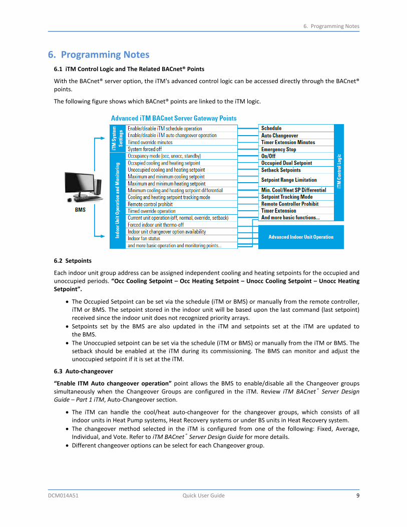
6. Programming Notes 6.1 iTM Control Logic and The Related BACnet® Points
With the BACnet® server option, the iTM's advanced control logic can be accessed directly through the BACnet® points.
The following figure shows which BACnet® points are linked to the iTM logic.
6.2 Setpoints
Each indoor unit group address can be assigned independent cooling and heating setpoints for the occupied and unoccupied periods. “Occ Cooling Setpoint – Occ Heating Setpoint – Unocc Cooling Setpoint – Unocc Heating Setpoint”.
• The Occupied Setpoint can be set via the schedule (iTM or BMS) or manually from the remote controller, iTM or BMS. The setpoint stored in the indoor unit will be based upon the last command (last setpoint) received since the indoor unit does not recognized priority arrays.
• Setpoints set by the BMS are also updated in the iTM and setpoints set at the iTM are updated to the BMS.
• The Unoccupied setpoint can be set via the schedule (iTM or BMS) or manually from the iTM or BMS. The setback should be enabled at the iTM during its commissioning. The BMS can monitor and adjust the unoccupied setpoint if it is set at the iTM.
6.3 Auto-changeover
“Enable ITM Auto changeover operation” point allows the BMS to enable/disable all the Changeover groups simultaneously when the Changeover Groups are configured in the iTM. Review iTM BACnet® Server Design Guide – Part 1 iTM, Auto-Changeover section.
• The iTM can handle the cool/heat auto-changeover for the changeover groups, which consists of all indoor units in Heat Pump systems, Heat Recovery systems or under BS units in Heat Recovery system.
• The changeover method selected in the iTM is configured from one of the following: Fixed, Average, Individual, and Vote. Refer to iTM BACnet® Server Design Guide for more details.
• Different changeover options can be select for each Changeover group.
6. Programming Notes
10 Quick User Guide DCM014A51
6.4 Setpoints Range Limitation
“Maximum Cooling Setpoint – Minimum Cooling Setpoint – Maximum Heating Setpoint – Minimum Heating Setpoint” are the points used to set the setpoints range limitations.
• The Out_Of_Service property for those points is true by default, which will need to change to false in order to set the range values or enable setpoint range limitation from the iTM.
• The Out_Of_Service properties of Min Cooling Setpoint or Max Cooling Setpoint are synced, if one of them changes (to True or False), the other will change and the same is true for the Min Heating setpoint and Max Heating setpoint.
• Suggested setpoint range is 70-74°F for cooling and 66-70°F for heating.
6.5 Schedule
“Enable iTM Schedule Operation” point allows the BMS to enable or disable all schedule programs configured on the ITM.
• The iTM can handle the everyday scheduling of the indoor unit groups. • There are 4 types of schedules that can be set in the iTM 7 day, Weekday/Weekend, Weekday/Saturday/
Sunday and Everyday.
6.6 Timed Override
“Time Override Minutes” is number of minutes that can be set from the BMS, which represent the timer extension on the iTM. This function sets up the time to stop the indoor unit.
“Time Override Operation” Monitors the status of the Timer Extension, and configures it for the indoor unit. When the timed override function is enabled for an indoor unit group, the units will be turned off automatically after the preset timer has expired if the unit is turned on during the unoccupied period.
6.7 Remote Controller Prohibits
Remote controller prohibits (On/Off, Mode and Setpoint) may be enabled/disabled by the objects provided to the BMS or the iTM.
• If the BMS sets the Setpoint Range Limitation, prohibiting the remote controller setpoint adjustment should not be enabled.
• The Remote Controller On/Off and Mode adjustment can be prohibited during the occupied hours, but the On/Off may need to be permitted during the unoccupied period for the Timed Override operation.
• When more than one indoor unit is connected to a single remote controller group, the BMS should only send commands to the indoor unit that is designated to receive the command for the remote controller group (unit#0). BMS should not send commands to other indoor units in the remote control group. If this object is sent to the other indoor units in the remote controller group, the indoor unit will not execute this command.
6.8 Forced System Shutdown
The “Forced System Off” point can be used to turn off all indoor unit groups connected to the iTM via the DIII-Net communication bus when an emergency signal has been received by the BMS.
• Emergency Stop program should have been configured and enabled in advance on the iTM. • Indoor unit groups cannot be restarted from the remote controller until the "Forced System Off" point has
been set to inactive.

6. Programming Notes
DCM014A51 Quick User Guide 11
6.9 Priority array
1. An object in the iTM BACnet® Server Gateway has a priority array, so that the highest priority value would be sent to the indoor unit.
2. The indoor unit does not have priority. The last change would be valid in the indoor unit from either the iTM BACnet® Server Gateway, iTM, or remote controller.
6.10 Restrictions
1. When a Present Value (PV) is set by the BMS, the iTM BACnet® Server updates the PV and keeps the previous PV.
2. The iTM BACnet® Server sends the new PV to Management Point in the iTM. The iTM BACnet® Server then starts a 10-min timer.
3. If the value in Management Point is changed (which means the indoor unit accepted the new value and sent back the new status to the iTM), the Management Point in the iTM sends the new value to the iTM BACnet® Server. The iTM BACnet® Server updates the PV and reset the 10-min timer.
4. If the value in Management Point is not changed (which means the indoor unit did not accept the new value and failed to update the status to the iTM), then nothing happens. Once the 10-min timer expires, the iTM BACnet® Server resets to the previous PV.
Restriction Examples
EXAMPLE 1 - Cool SP max
Step BMS BACnet® Server in ITM Management Point in ITM
Pre-condition • Unocc Cool SP: 80°F • Cool SP range: 70-76°F
• Cool Setback SP: 80°F • Cool SP range: 70-76°F
#1 • Sets Cool SP max 85°F • PV: 85°F, previous PV: 76°F • Start 10-min timer
#2 • Sends 85°F to Management Point • Cool SP max 85°F is rounded to 78°F due to
Cool Setback SP 80°F. • Cool SP range: 70-78°F (Changed)
#3 • PV 78°F • Reset 10-min timer
• Updates 78°F to the BACnet® Server
#1 • Sets Cool SP max 85°F again
• PV: 85°F, previous PV: 78°F • Start 10-min timer
#2 • Sends 85°F to Management Point • Cool SP max 85°F is rounded to 78°F due to
Cool Setback SP 80°F • Cool SP range: 70-78°F (No change)
#3 • When 10-min timer expires, PV back to 78°F

6. Programming Notes
12 Quick User Guide DCM014A51
EXAMPLE 2 - Cool SP
Step BMS BACnet® Server in ITM Management Point in ITM
Pre-condition • Cool SP range: 70-78°F • Cool SP: 72°F
• Cool SP range: 70-78°F • Cool SP: 72°F
#1 • Sets Cool SP 68°F • PV: 68°F, previous PV: 72°F • Start 10-min timer
#2 • Sends 68°F to Management Point • Cool SP 68°F is rounded to 70°F due to Cool
SP range 70-78°F • Cool SP: 70°F (Changed)
#3 • PV 70°F • Reset 10-min timer
• Sends 70°F to BACnet® Server
#1 • Sets Cool SP 68°F again
• PV: 68°F, previous PV: 70°F • Start 10-min timer
#2 • Sends 68°F to Management Point • Cool SP 68°F is rounded to 70°F due to the
Cool SP range 70-78°F • Cool SP: 70°F (No change)
#3 • When 10-min timer expires, PV back to 70°F
EXAMPLE 3 – Operation mode to Changeover slave unit
Step BMS BACnet® Server in ITM Management Point in ITM Indoor Unit Pre-condition • Operation mode: Cool • Operation mode: Cool • Operation mode: Cool
#1 • Sets
Operation mode Fan
• PV: Fan, previous PV: Cool • Start 10-min timer
#2 • Sends Fan mode to Management Point • Send Fan mode to Indoor Unit
• Accepts Fan mode • Status update to ITM as
Operation mode Fan
#3 • PV Fan • Reset 10-min timer
• Operation mode: Fan (Changed)
• Send Fan to BACnet® Server
#1 • Sets
Operation mode Heat
• PV: Heat, previous PV: Fan • Start 10-min timer
#2
• Sends Heat to Management Point • Send Heat to Indoor Unit • Cannot accept Heat due
to changeover slave unit
• Operation mode: Fan (No change)
• Periodical status report to ITM as Operation mode Fan
#3 • When 10-min timer expires, PV back to Fan

Summary
DCM014A51 Quick User Guide 13
Summary iTM BACnet® Server (DCM014A51) is a software license that can be added to an iTM Ver2.04 or higher. The iTM BACnet® Server will expose indoor units as BACnet® objects after the commissioning process. Indoor units registered as management points in the iTM are monitored and controlled by the BMS without additional hardware devices. The iTM Auto Changeover, Setpoint Range Limit, Setback, Dual Setpoint logic and Schedule control can be utilized by the BMS. The iTM BACnet® virtual router function will provide a unique device ID for each indoor unit group. The iTM BACnet® Server Design Guide is the main document that describes the BACnet® server functions details available to the BMS integrators.
Our continuing commitment to quality products may mean a change in specifications without notice.
© 2017 DAIKIN NORTH AMERICA LLC Houston, Texas USA
www.daikincomfort.com
WARNING
• Only qualified personnel must complete installation.
• Consult your Daikin dealer regarding relocation and reinstallation of the remote controller. Improper installation may result in electric shock or fire.
• Electrical work must be performed in accordance with relevant local and national regulations, and with the instructions in this installation manual. Improper installation may cause electric shock or fire.
• Only use specified accessories and parts for installation. Failure to use specified parts may result in electric shock, fire, or controller damage.
• Do not disassemble, reconstruct, or repair. Electric shock or fire may occur.
• Only use specified wiring and verify all wiring is secured. Assure no external forces act on the terminal connections or wires. Improper connections or installation may result in electric shock or fire.
• Confirm power to the unit is OFF before touching electrical components.
BACnet® is a registered trademark of ASHRAE.
UGUS_DCM014A51_03-17