
Intelligent Ships Symposium May 20-21, 2015 Ranjit Amgai, PhD Dept. of Electrical and Computer...
31
Intelligent Ships Symposium May 20-21, 2015 Ranjit Amgai, PhD Dept. of Electrical and Computer Engineering Mississippi State University AUTONOMIC MANAGEMENT OF SHIPBOARD POWER SYSTEMS AND ITS CHALLENGES
-
Upload
blaze-johnston -
Category
Documents
-
view
213 -
download
0
Transcript of Intelligent Ships Symposium May 20-21, 2015 Ranjit Amgai, PhD Dept. of Electrical and Computer...

Intelligent Ships Symposium May 20-21, 2015
Ranjit Amgai, PhD
Dept. of Electrical and Computer EngineeringMississippi State University
AUTONOMIC MANAGEMENT OF SHIPBOARD POWER SYSTEMS AND ITS
CHALLENGES

MOTIVATION AND CHALLENGES
Increasing power demand with Quality of Service(QoS) requirements Uncertain power demand profiles requiring the continuity in power
supply. Meeting the design specifications to overcome several challenges for
normal and faulty conditions via manual tuning is not only exhausting and fallible, but also infeasible.
Handling such complexities for uncertain operating conditions require the generic management framework that adds the self-managing and self-healing capabilities given the high-level objectives.
2
Deliver Right Power to Right Load at Right Time

AUTONOMIC COMPUTING
3

LITERATURE REVIEW
4
Expert System [Karim-2002]: Optimal power flow, optimal load shedding, and
voltage controls using rule based system [Morse-2012]: Load and Configuration management verified
through expert system rules on physics based simulation.
Feedback Control Theory [Radan-2008]: Observer based fast load reduction.
Advanced Artificial Intelligence [Solanki-2005]: Multi-agent based implementation for data
sharing, communications, and reconfiguration [Qunying-2012]: Multi-agent based framework for power
management functionalities. [Mitra-2011]: Modified PSO algorithm for reconfiguration and
critical load balancing

LITERATURE REVIEW
5
Model Predictive Approach for Management Framework [Seenumani-2010]: Reference governor based hierarchical
controller using trajectory optimization [Licheng-2011]: MPC based power system control architecture
for protection [Torstein-2012]: MPC based framework for drilling ship with load
sharing control
Distributed Architecture [Qunying-2012]: Multi-agent based distributed framework for
Eship power management functionalities. [Venkat-2008, Moradzadeh-2011]: Distributed MPC applied to
terrestrial power system applications

MODEL-BASED CONTRIBUTIONS
It is highly configurable and can be tuned for multiple performance specifications.
The framework is generic, modular and scalable with respect to system components.
It provides flexibility for using additional algorithms and the idea can be extended further to smart grid applications, thus strengthening the automation.
Novel model-based distributed management control framework provides fault-tolerant and self-configurable platform.
6

MANAGEMENT FRAMEWORK

SYSTEM CONTROLS FRAMEWORK
8
Key Components of Framework Model: System Abstraction Control Algorithm: Limited
Lookahead Control (LLC) Optimizer: Search Space Modules: SPS Diagnosis,
Dispatch Control, Shunt compensation control, etc

SPS DIAGNOSIS SUPPORT
9
Goal: To develop the intelligent diagnosis support module that classifies the Shipboard Power System operation states to assist the supervisory controls architecture.
Computation Burden Fast training Adaptive Uncertainties Relative ease of system
development
Normal, Alert, Emergency Assists the control framework Screening of contingencies help for
preventing rescheduling Time to trigger control actions Situational awareness for Operator Supports SPS reliability
Motivation SPS Assessment

EVALUATION INDEX
Offline Data processing Post Contingency Screening Identification of vital/ Non-vital load loss Objective results amount of Real Power cut
10

FLOWCHART FOR DIAGNOSIS
11
Signal Conditioning
Training Complete?
Data Measurement
Feature Selection
Training Data Set Testing Data Stream
Bayes’ Model
Update
Classification o/p
N
Classification steps Implemented on Matlab/Weka
API Supports the incremental
Training

CASE-STUDY
12
300 representative samples 60% to 140% load variation 97.67% classification accuracy 25ms to test the data 10ms to build/update the model
N Events Evaluation Index Value
Result
1 Generator Outage(MTG1) 34 Emergency
2 One Line Outage (L10) 0.5 Normal
3 Double Line Outage (L1+L10) 34 Emergency
4 Double Line Outage(L2+L7) 0 Normal
5 One Generator + One Line Outage (MTG1+L1)
15 Emergency
6 One Generator + One Line Outage(ATG1+L2)
3 Alert

VOLTAGE CONTROL MODULE
13
Goal: Develop a module for handling system faults through predictive optimal tuning of real time control parameters for voltage control from the finite set of control actions
Lookahead Horizon: ‘Limit Horizon’ can be estimated by offline simulation.
Control Set: For non finite control sets, “discretized” approximation
Input Set: Complexity ( )
Where, b is the size of input set and d is the horizon depth. Enhanced Search Techniques(A*), search space reduction Approximation of control input domain
Modeling Abstraction
( )db
Controller Performance

14
LOOK-AHEAD CONTROL SCHEME Key Components
System model and control objective System input forecast Controlling parameters Constraints and performance specifications Lookahead Horizon:
System Model Set of difference equations relating the objective Function to the
finite set of constrained input set( 1) ( ( ), ( ), ( ( 1, )), ( ))kx k f x k u k w k r e k

LOOK-AHEAD CONTROL SCHEME
15
For each step k:
And picks the best:
Selection of the next step is based on a map that defines how close the current state is to Xs
Controller constructs a tree of all future states up to certain depth. A path that minimizes the distance to Xs is traced back to current state
and the initial step is selected.
Selection of the next step is based on a map that defines how close the current state is to Xs
Controller constructs a tree of all future states up to certain depth. A path that minimizes the distance to Xs is traced back to current state
and the initial step is selected.
],1[
:horizon Prediction
hkk
k+hk+3k+2k+1
)1(ˆ kx
)2(ˆ kx )(ˆ hkx )3(ˆ kx
x(k)
sX

OPTIMAL CONTROL PROBLEM
16
Subject to:
Dynamics:
Input space:
Constraints:

17
Component wise
Differential Equations
Coupling Linearization Discretize
IMPLEMENTATION STRUCTURE
18
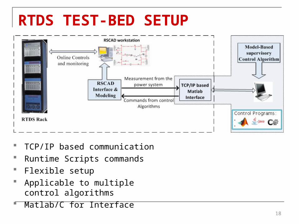
RTDS TEST-BED SETUP
TCP/IP based communication Runtime Scripts commands Flexible setup Applicable to multiple control algorithms Matlab/C for Interface

19
COMPLEXITY REDUCTION METHOD Number of explored states: A* Algorithm Offline computed hash table Pre-compute the knowledge base using existing model Utility function assists the computation of heuristics table Significant computation speedup Use of existing system model
[Abdelwahed-2009]

20
PERFORMANCE COMPARISON
Capacitor Tuning
Performance Comparison for Various Search Strategies

21
SYSTEM PERFORMANCE
RTDS Open Loop Fault Scenario RTDS Closed Loop: 1% Load Change
RTDS Closed Loop RTDS Closed Loop: 2.5% Load Change

DISTRIBUTED MANAGEMENT FRAMEWORK
22
Goal: To enhance the computation efficiency and address the system management issues by keeping the frequency in limits by managing No-load frequency and fuel rate.
Complexity of system design increases as it grows bigger Minimize the single point of failure Enhance computation time Formally define the problem Flexible modular approach Adds robustness towards failure
Motivation

23
SPS APPLICATION
Coordinator influences the first level control units in certain manner to satisfy the coordination condition.
Changes the infimal performance function Finds the set of coordination variables The applied controls depends upon the infimal
units output and the control inputs Computes an optimal set of control input u
[ωNL,1, ωNL,2 ] for each subsystem by satisfying the operational constraints of the subsystems.
β1……. βn
System Modeling

24
1. Load sharing ratio2. Utility value3. Computational Aspect
1. Hierarchical Units Interaction2. Subsystem Processing time
The ratio of explored states:
where, U is the set of control input, Ik is the iterations among the subsystem
and coordinator, N is the number of subsystems, m is the
input pair, H is the prediction horizon steps.
Performance Parameters
1. Frequency2. Load Sharing3. No-load frequency4. Utility value5. Latency6. Scale of Implementation7. Controller Interaction8. Interaction error
Performance Comparison
PERFORMANCE OF CONTROL APPROACH

25
SYSTEM PERFORMANCEWith constant No-load frequency With the application of IBP

PERFORMANCE EVALUATIONNo load frequency
Interaction Errors
Power sharing
34
It can be applied to a general class of power system applications due to the generic nature of the approach.
It efficiently manages the power management specifications by handling the load sharing and fault minimization simultaneously.
It also provides better utility of the deployment and reduces the computational overhead compared to a centralized approach.
The developed approach shows robustness towards the varying load conditions.
BENEFITS OF THE APPROACH
35

Keeping the Model simple and Accurate Abstraction is the key
Control Inputs Impact Long term system performance Analysis
Computation Speed For transient level control Benefit/Cost Analysis
Algorithm Selection Open Architecture Framework Application specific algorithm
CHALLENGES OF THE APPROACH
35

Human Interface Iterative approach to setting policies
Policy Goal-based and Utility-function based Not just low-level policies
Demonstrate the effectiveness Relatively new scheme on research community More research effort helps to mature
CHALLENGES OF THE APPROACH
35

Extension of Modules Add other modules to consolidate the power management
concept in SPS. Formally analyze the approach further and proven for stability Extensive application for MVDC systems Scale to real-time cases for validation
FUTURE RESEARCH
37

Thank You!!!
Questions ?