
INTELLIGENT SENSORLESS AND ROTOR FLUX LINKAGE CONTROL ... · PDF fileThe permanent-magnet...
11
1 Research Scholar, St. Peter’s University, Avadi, Chennai-54 2 Professor & Head, Dept. of EEE, St. Xavier’s Catholic College of Engineering, Kanyakumari, Tamilnadu. I J E E E S : Vol. 6 • No. 1 • January-June 2014 INTELLIGENT SENSORLESS AND ROTOR FLUX LINKAGE CONTROL DESIGN OF PMSM SERVO DRIVE 1 S. Radhika and 2 M. Marsalin Beno The permanent-magnet synchronous motors (PMSM) are widely used in industrial servo applications due to its high power density. However, there exists a risk of potential irreversible demagnetization in the rotor magnets due to high temperature rise or large demagnetizing current. Since the rotor permanent magnet (PM) flux linkage decreases as the PM temperature increases, it is desirable to estimate the rotor flux linkage value since the decrease in rotor flux linkage in turn reduces the performance of the drive. Sensor less control method is also involved to improve the performance of machine. The proposed method consists of a thermocouple and an adaline estimator which estimates the temperature of the machine and distortion in the voltage respectively. The thermocouple is placed on either sides of the stator. By continuously monitoring or tracking the rotor flux linkage and compensating the VSI nonlinearity the performance of the PMSM can be improved. Hence the machine can possess high efficiency. Keywords: PMSM, Fuzzy Controller, Extrusion System, Fuzzy PID, LabVIEW program, Accelerated fuzzy PI, Intelligent Hybrid Fuzzy, Neuro Fuzzy Controller, PWM, PIDcontroller, Neural Controller, , Synthetic Optimizing. I. INTRODUCTION The permanent-magnet synchronous motors (PMSM) are widely employed in industrial servo drives, electric/hybrid electric vehicles, wind power generators etc due to its high power density. During the continuous operation of the motor the temperature of the rotor may increase in high level as it is a permanent magnet. Also there occur some problems in the permanent magnet during the time of start up, synchronization and voltage regulation. The increase in temperature of the rotor further decreases the rotor flux linkage and hence the performance of the drive may get affected. So the continuous monitoring of the rotor flux linkage is necessary to increase the performance. The magnetic materials of the permanent magnet synchronous motors are sensitive to temperature; for instance, the magnet can lose its magnetic qualities at high temperatures. Hence the rotor temperature must be supervised. It is important to obtain accurate machine parameters for online fault diagnosis and monitoring rotor/stator temperature, as well as for achieving high control performance. The rotor flux linkage can be estimated using the sensor less operation of PMSM drive because of the high cost and difficulty of installing sensors. II. PROPOSED SYSTEM A method for online estimating the PMSM rotor flux linkage and distorted voltage V dead due to VSI nonlinearity is proposed, which is suitable for most widely used id = 0 control and also used for the condition monitoring of the rotor PM. The winding resistance at normal temperature and temperature coefficient of winding resistance are measured before the implementation of the proposed method. Thermocouples are employed for measuring the temperature variation in stator winding resistance, which is used for aiding the estimation of rotor flux linkage. Thus, this method does not need to inject any signals such as id•0 and dc voltage pulse or change the PMSM working condition. Also, it is advanced that the accuracy of the proposed rotor flux linkage estimation will not suffer from the variation of dq-axis inductances and has taken into account the compensation of estimation error due to VSI nonlinearity. This method is experimentally validated in a field oriented vector control system and shows good performance in tracking the variation of the PMSM rotor flux linkage and compensating the VSI nonlinearity. Since it is suitable for only id = 0 control, the estimation for id‘“0 will also being proposed.
Transcript of INTELLIGENT SENSORLESS AND ROTOR FLUX LINKAGE CONTROL ... · PDF fileThe permanent-magnet...

1 Research Scholar, St. Peter’s University, Avadi, Chennai-542 Professor & Head, Dept. of EEE, St. Xavier’s Catholic College of Engineering, Kanyakumari, Tamilnadu.
I J E E E S : Vol. 6 • No. 1 • January-June 2014
INTELLIGENT SENSORLESS AND ROTOR FLUX LINKAGECONTROL DESIGN OF PMSM SERVO DRIVE
1S. Radhika and 2M. Marsalin Beno
The permanent-magnet synchronous motors (PMSM) are widely used in industrial servo applications due to its high power density.However, there exists a risk of potential irreversible demagnetization in the rotor magnets due to high temperature rise or largedemagnetizing current. Since the rotor permanent magnet (PM) flux linkage decreases as the PM temperature increases, it isdesirable to estimate the rotor flux linkage value since the decrease in rotor flux linkage in turn reduces the performance of the drive.Sensor less control method is also involved to improve the performance of machine. The proposed method consists of a thermocouple andan adaline estimator which estimates the temperature of the machine and distortion in the voltage respectively. The thermocouple isplaced on either sides of the stator. By continuously monitoring or tracking the rotor flux linkage and compensating the VSInonlinearity the performance of the PMSM can be improved. Hence the machine can possess high efficiency.
Keywords: PMSM, Fuzzy Controller, Extrusion System, Fuzzy PID, LabVIEW program, Accelerated fuzzy PI, Intelligent HybridFuzzy, Neuro Fuzzy Controller, PWM, PIDcontroller, Neural Controller, , Synthetic Optimizing.
I. INTRODUCTION
The permanent-magnet synchronous motors (PMSM)are widely employed in industrial servo drives,electric/hybrid electric vehicles, wind powergenerators etc due to its high power density. Duringthe continuous operation of the motor thetemperature of the rotor may increase in high levelas it is a permanent magnet. Also there occur someproblems in the permanent magnet during the timeof start up, synchronization and voltage regulation.The increase in temperature of the rotor furtherdecreases the rotor flux linkage and hence theperformance of the drive may get affected. So thecontinuous monitoring of the rotor flux linkage isnecessary to increase the performance. The magneticmaterials of the permanent magnet synchronousmotors are sensitive to temperature; for instance,the magnet can lose its magnetic qualities at hightemperatures. Hence the rotor temperature must besupervised. It is important to obtain accuratemachine parameters for online fault diagnosis andmonitoring rotor/stator temperature, as well as forachieving high control performance. The rotor fluxlinkage can be estimated using the sensor lessoperation of PMSM drive because of the high costand difficulty of installing sensors.
II. PROPOSED SYSTEM
A method for online estimating the PMSM rotor fluxlinkage and distorted voltage V dead due to VSInonlinearity is proposed, which is suitable for mostwidely used id = 0 control and also used for thecondition monitoring of the rotor PM. The windingresistance at normal temperature and temperaturecoefficient of winding resistance are measured beforethe implementation of the proposed method.Thermocouples are employed for measuring thetemperature variation in stator winding resistance,which is used for aiding the estimation of rotor fluxlinkage. Thus, this method does not need to injectany signals such as id•0 and dc voltage pulse orchange the PMSM working condition. Also, it isadvanced that the accuracy of the proposed rotorflux linkage estimation will not suffer from thevariation of dq-axis inductances and has taken intoaccount the compensation of estimation error due toVSI nonlinearity. This method is experimentallyvalidated in a field oriented vector control systemand shows good performance in tracking thevariation of the PMSM rotor flux linkage andcompensating the VSI nonlinearity. Since it is suitablefor only id = 0 control, the estimation for id‘“0 willalso being proposed.

S. Radhika and M. Marsalin Beno
72
III. OVERALL BLOCK DIAGRAM generated. Then the actual speed and the referencespeed can be compared using the comparator andthe error is cleared using the PI controller. The threephase components of the current from the PMSM areconverted into two phase components by using park’stransformation. The d-axis component of the currentis made zero in order to improve the performanceand accuracy. The dq-axis currents are converted intorespective voltages and again the dq-axis voltagesare converted into three phase voltages (va, vb, vc)which are used for the generation of PWM pulses tothe inverter. The supply for the PMSM is fed by thethree phase inverter.
V. ONLNE ESTIMATION OF ROTOR FLUXLINKAGE
Figure 1: Overall Block Diagram
dv
dt
The block diagram consists of a source, inverter,PMSM, estimation part and a controller. The sourcecan be a dc source which is fed to the inverter andthe inverter uses the space vector pulse widthmodulation to convert the dc source to ac supply forthe motor. The online estimation of parameters isbased on the simple fact that the rate of change offlux will produce emf in the circuit. This can be givenby
IV. SENSOR LESS CONTROL OF PMSM
The sensor less control of the permanent magnetsynchronous motor is used to determine the angularvelocity without using any sensors.
The rotor speed of the PMSM can be fed to thespeed calculator from which the actual speed is
Figure 2: Sensor less control of permanent magnetsynchronous motor
Figure 3: Process of online estimation of rotor flux linkageand compensating VSI non linearity
Mathematical model for the estimation of rotorflux linkage and distortion in the voltage of thevoltage source inverter can be given by,
The dq-axis equations of the PMSM are,
Lqdid R vdid iq
dt Ld Ld Ld
diq vqR Ld miq id
dt Lq Lq Lq Lq�
The steady-state dq-axis equations of the PMSMare,
vd(k) = Rid(k) – Lq�(k)iq(k)
vq(k) = Riq(k) + Ld�(k)id(k) + �m�(k)
Where,

Intelligent Sensorless and Rotor Flux Linkage Control Design of PMSM Servo Drive
73
k� Index of the discrete sampling instant.When id = 0, the equations can be simplified into,
vd(k) = –Lq�(k)iq(k)
vq(k) = Riq(k) + �m�(k)The dq-axis equations including voltage
distortion due to VSI non-linearity is given by,
ddt
LdidLqiq = – R
idiq
Lq iq
Ld id m� +**
vdvq +Vdead
DdDq
Where Dd and Dq are expressed as,
22 cos si gn( )cos33
( )2 2sin sin +
( )3 3
iasDd
sign ibsDqsign ics
sign (i) = 1, i>=0
-1, i<0.
Using dq-axis steady state equations of thePMSM, the rotor flux linkage equation can beestimated as,
diqLq vq Rqiq Ldid m
dt
diqm Lq vq Rqiq Ldid
dt
Lq diq vq Rqiqm Ldid
dt�
The VSI nonlinearity in the system can bemeasured using,
vd + DdVdead = Rid –Lq�iq
DdVdead = Rid – Lq�iq – vd
LqiqRid vdVdead
Dd Dd
Actual value of winding resistance can bemeasured using,
R = Ro+ TCR(T2-To) �(A)Where,
Ro � Winding resistance at roomTemperature (To=27degree)
TCR� Temperature Coefficient.
T2� Increase in temperature Running.
VI. COMPENSATION OF VSI NON LINEARITY
With aiding from the estimated V dead andcomputed winding resistance R, the rotor flux linkagecan be finally estimated by (A). The completediagram of the proposed method is shown in Fig. 4and the whole estimation are divided into three steps:
(1) At standstill, the stator winding resistance valueR0 at normal temperature T0 is measured bymilliohm meter and two sets of thermocoupleare employed for measuring the variation ofstator winding temperature T2, which will beused for real time computing the actual value ofstator winding resistance R.
(2) The value of V dead of distorted voltage due toVSI nonlinearity is online estimated from the d-axis equation and employed for the compensationof inverter nonlinearity.
(3) The rotor flux linkage is finally estimated fromthe q-axis equation with the aiding from computedwinding resistance and Vdead.
Figure 4: Flowchart for the estimation of rotor flux linkage
The estimation of the rotor flux linkage underdifferent working conditions is depicted in Fig. 5, inwhich the estimation and compensation of Vdeadare started after t = 10 s. From Fig. 5, it is obviousthat the estimated rotor flux linkage at 300 r/min(68.3 mWb) is close to that under no-load condition

S. Radhika and M. Marsalin Beno
74
(70.7 mWb) and the slight decrease in the rotor fluxlinkage (70.7–68.3 = 2.4 mWb) can be explained thatit is caused by the variation of flux density due to onload. However, the estimated rotor flux linkage at150 r/min (73.3 mWb) is slightly larger than thatunder no-load condition (70.7 mWb), which iscontrary to the basic theory that the rotor flux linkageunder loaded condition should be smaller than thatunder no-load condition. This estimation error canbe explained that there are still influences from othernonlinearities such as non ideal positionmeasurement, current offsets, and non idealmeasurement of dc-bus voltage.
VII. PERMANENT MAGNET SYNCHRONOUSMOTOR
A permanent magnet synchronous motor is a motorwhere the excitation field is provided by a permanentmagnet instead of a coil. Synchronous generators arethe majority source of commercial electrical energy.They are commonly used to convert the mechanicalpower output of steam turbines, gas turbines,reciprocating engines, hydro turbines and windturbines into electrical power for the grid. In themajority of designs the rotating assembly in the centerof the generator the “rotor” contains the magnet,and the “stator” is the stationary armature that iselectrically connected to a load. A set of threeconductors make up the armature winding instandard utility equipment, constituting three phasesof a power circuit that correspond to the three wireswe are accustomed to see on transmission lines.Ifthe rotor windings are arranged in such a way as toproduce the effect of more than two magnetic poles,then each physical revolution of the rotor results inmore magnetic poles moving past the armature
windings. Each passing of a north and South Polecorresponds to a complete “cycle” of a magnet fieldoscillation. Therefore, the constant of proportionalityis
,120P
Where P is the number of magnetic rotor poles(almost always an even number), and the factor of120 comes from 60 seconds per minute and two polesin a single magnet;
( ) .120P
f Hz RPM
In a permanent magnet generator, the magneticfield of the rotor is produced by permanent magnets.Other types of generator use electromagnets toproduce a magnetic field in a rotor winding. The
Figure 5: Estimated rotor flux linkage with and withoutcompensation at normal temperature
Figure 6: Rotor of a large water pump. The slip rings can beseen below the rotor drum.
direct current in the rotor field winding is fedthrough a slip-ring assembly or provided by abrushless exciter on the same shaft. Synchronousmotors fall under the more general categoryof synchronous machines which also includes thesynchronous generator. Generator action will beobserved if the field poles are “driven ahead of theresultant air-gap flux by the forward motion ofthe prime mover”. Motor action will be observed ifthe field poles are “dragged behind the resultantair-gap flux by the retarding torque of a shaft load”.There are two major types of synchronous motorsdepending on how the rotor is magnetized: non-excited and direct-current excited.

Intelligent Sensorless and Rotor Flux Linkage Control Design of PMSM Servo Drive
75
(a) Construction typically use an anti-reversing mechanism to ensurestarting in the correct direction.
(c) Use as Synchronous Condenser
Figure 7: Stator winding of a large water pump
The principal components of a synchronousmotor are the stator and the rotor. The stator ofsynchronous motor and stator of induction motorare similar in construction. The stator framecontains wrapper plate. Circumferential ribs and keybars are attached to the wrapper plate. To carry theweight of the machine, frame mounts and footingsare required. When the field winding is excitedby DC excitation, brushes and slip rings are requiredto connect to the excitation supply. The field windingcan also be excited by a brushless exciter. Cylindrical,round rotors, (also known as non salient pole rotor)are used for up to six poles. In some machines orwhen a large number of poles are needed, a salientpole rotor is used. The construction of synchronousmotor is similar to that of a synchronous alternator.
(b) Starting Methods
Above a certain size, synchronous motors are notself-starting motors. This property is due to theinertia of the rotor; it cannot instantly follow therotation of the magnetic field of the stator. Since asynchronous motor produces no inherent averagetorque at standstill, it cannot accelerate tosynchronous speed without some supplementalmechanism. Large motors operating on commercialpower frequency include a “squirrel cage” inductionwinding which provides sufficient torque foracceleration and which also serves to damposcillations in motor speed in operation. Smallsynchronous motors are commonly used in line-powered electric mechanical clocks or timers that usethe power line frequency to run the gear mechanismat the correct speed. Synchronous motors in clocks
Figure 8: V-curve of a synchronous machine
By varying the excitation of a synchronousmotor, it can be made to operate at lagging, leadingand unity power factor. Excitation at which the powerfactor is unity is termed normal excitation voltage.When the motor is over excited, the back emf willbe greater than the motor terminal voltage. Thiscauses a demagnetizing effect due to armaturereaction. This ability to selectively control powerfactor can be exploited for power factor correction ofthe power system to which the motor is connected.Since most power systems of any significant size havea net lagging power factor, the presence ofoverexcited synchronous motors moves the system’snet power factor closer to unity, improving efficiency.Such power-factor correction is usually a side effectof motors already present in the system to providemechanical work, although motors can be runwithout mechanical load simply to provide power-factor correction. In large industrial plants such asfactories the interaction between synchronous motorsand other, lagging, loads may be an explicitconsideration in the plant’s electrical design.
Steady state stability limitT = Tmax sin �Where,T is the torque��is the torque angleTmax is the maximum torque
S. Radhika and M. Marsalin Beno
76
Here,
max
3
g S
VET
X
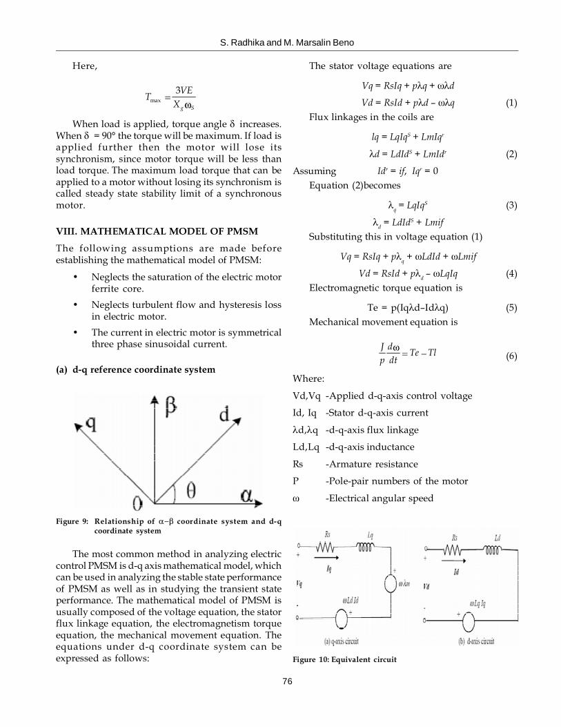
When load is applied, torque angle � increases.When � = 90° the torque will be maximum. If load isapplied further then the motor will lose itssynchronism, since motor torque will be less thanload torque. The maximum load torque that can beapplied to a motor without losing its synchronism iscalled steady state stability limit of a synchronousmotor.
VIII. MATHEMATICAL MODEL OF PMSM
The following assumptions are made beforeestablishing the mathematical model of PMSM:
• Neglects the saturation of the electric motorferrite core.
• Neglects turbulent flow and hysteresis lossin electric motor.
• The current in electric motor is symmetricalthree phase sinusoidal current.
(a) d-q reference coordinate system
The stator voltage equations are
Vq = RsIq + p�q + ��d
Vd = RsId + p�d – ��q (1)Flux linkages in the coils are
lq = LqIqS + LmIqr
�d = LdIdS + LmIdr (2)
Assuming Idr = if, Iqr = 0Equation (2)becomes
�q = LqIqS (3)
�d = LdIdS + LmifSubstituting this in voltage equation (1)
Vq = RsIq + p�q + �LdId + �Lmif
Vd = RsId + p�d – �LqIq (4)Electromagnetic torque equation is
Te = p(Iq�d–Id�q) (5)Mechanical movement equation is
J dTe Tl
p dt (6)
Where:
Vd,Vq -Applied d-q-axis control voltage
Id, Iq -Stator d-q-axis current
�d,�q -d-q-axis flux linkage
Ld,Lq -d-q-axis inductance
Rs -Armature resistance
P -Pole-pair numbers of the motor
� -Electrical angular speed
Figure 9: Relationship of coordinate system and d-qcoordinate system
The most common method in analyzing electriccontrol PMSM is d-q axis mathematical model, whichcan be used in analyzing the stable state performanceof PMSM as well as in studying the transient stateperformance. The mathematical model of PMSM isusually composed of the voltage equation, the statorflux linkage equation, the electromagnetism torqueequation, the mechanical movement equation. Theequations under d-q coordinate system can beexpressed as follows: Figure 10: Equivalent circuit

Intelligent Sensorless and Rotor Flux Linkage Control Design of PMSM Servo Drive
77
IX. SPACE VECTOR PULSE WIDTHMODULATION
(a) Space Vector Modulation
Space vector modulation (SVM) is an algorithm forthe control of pulse width modulation (PWM). It isused for the creation of alternating current(AC) waveforms; most commonly to drive 3phase AC powered motors at varying speeds fromDC using multiple class-D amplifiers. There arevarious variations of SVM that result in differentquality and computational requirements. One activearea of development is in the reduction of totalharmonic distortion (THD) created by the rapidswitching inherent to these algorithms.
(b) Principle
inverters do exist.In these strategies the switchingvectors define a 3D shape (a) hexagonal prism in ���coordinates or a dodecahedron in abc Three-Dimensional Space Vector Modulation in abccoordinates) rather than a 2D hexagon.
(c) Space Vector Pulse width ModulationTechnique
In motor theory, motor speed is defined by theformula
N = 60 f
p (7)
where f-Power frequency and p-pole pair
Through the formula ,speed regulate needchange the power frequency or the motor pole pairs,and change power frequency easier than changemotor pole pairs, so, at present, the great mass ofmotor speed regulate use frequency convert.Currently, use the type of: AC-DC-AC. It’s means,convert 3-phase power AC into DC, then, invert theDC into 3-phase AC and change frequency. First,define the 3-phase power AC interphase voltage is:
2 (cos )Ua U t
22 cos
3Ub U t (8)
42 cos
3Uc U t
Convert this 3-phase AC voltage into stationarysystem (�-�):
2/3( 0.5 0.5 2 (cos )U Ua Ub Uc U t
3 32 /3 2 (sin )
2 2U Ub Uc U t (9)
Take this into voltage space vector:
Us = U��+ jU�
Us = �2(cos�t + jsin�t) = �2 Uej�t (10)
This equation is circular in plural plane. So, inmotor theory, invariableness’ voltage(U) andfrequency, stator voltage space vector in plural planemove along with a circularity , and space vector movea cycle in a power frequency cycle. After Clark
Figure 11: Topology of a basic three phase inverter
A three phase inverter as shown to the right mustbe controlled so that at no time are both switches inthe same leg turned on or else the DC supply wouldbe shorted. This requirement may be met by thecomplementary operation of the switches within aleg. i.e. if A+ is on then A– is off and vice versa. Thisleads to eight possible switching vectors for theinverter, V0 through V7 with six active switchingvectors and two zero vectors.To implement spacevector modulation a reference signal Vref is sampledwith a frequency fs (Ts = 1/fs). The reference signalmay be generated from three separate phasereferences using the ��� transform.
The reference vector is then synthesized using acombination of the two adjacent active switchingvectors and one or both of the zero vectors. Variousstrategies of selecting the order of the vectors andwhich zero vector(s) to use exist. Strategy selectionwill affect the harmonic content and the switchinglosses.More complicated SVM strategies for theunbalanced operation of four-leg three-phase

S. Radhika and M. Marsalin Beno
78
transforming, phase voltage in the three-phase ABCplane coordinate system can be change into áâ right-angled coordinate system.
(d) DC-AC converter
(e) Procedure for SVPWM production
1. Make sure the Uref belong to which sector.
2. Calculate X,Y,Z which are used to determine opentime of 2 adjacent basic vector.
3. Determine each conduction time t1,t2 for 2adjacent basic vector.
4. Calculate taon, tbon, tcon which are used tocreate SVPWM waveform.
Figure 12: dc to ac converter
It has six power switches a, b, c, a’, b’, c’ whichare grouped into S(a, b, c) and S(a’, b’, c’).It meanseach voltage vector is coded by three digit numberand have eight possible switching states.
Consider the state S(1,0,0).
The point [a], [b’], [c’] switch ON, and [a], [b],[c]switch OFF.
Uan=Udc and Ubn=Ucn=0
Substitute this values in (3.5)
23 3 3
Udc vdc vdcUa Ub Uc (11)
Graphical representation of all combinations isthe hexagon shown in Figure 13. There are six non-zero vectors, U0, U60, U120, U180, U240, U300, andtwo zero vectors, O000 and O111 defined in á, âcoordinates.
Figure 13: Vector representation
Figure 14: Block diagram of SVPWM
(f) Judgement Sector
According to figure 14, when Vout is given in theform of the component Vout�, Vout� on �-�coordinate system, we can use equation (8) tocalculate B0, B1, B2.
B0 = U�B1 = sin 60 U� – sin 30 U�B2 = -sin 60 U� – sin 30 U� (12)The value of equation P can be written as
P = 4sign(B2) + 2sign(B1) +sign(B0) (13)where sign(x) is sign function.
Then the sector number can be given by
Table 1Sector Number
P 1 2 3 4 5 6
Sector number 2 6 1 4 3 5
(g) Act Time of Basic Voltage Vector
The relationship between the act time of the basicvoltage vectors t1, t2 and X, Y, Z, and sector N isshown as follows:
Table 2Act Time of Voltage Vector
Sector N 1 2 3 4 5 6
t1 Z Y -Z -X X -Yt2 Y -X X Z -Y -Z
Intelligent Sensorless and Rotor Flux Linkage Control Design of PMSM Servo Drive
79
where
X = �3V�Ts/Udc
Y = 0.5(�3V��+ 3V�)Ts/Udc (14)
Z = 0.5(�3V�-3V�)Ts/Udc
(h) Calculation of Switching Time
Firstly, Ta, Tb, Tc can be given by
1 2 1 12 2 2
T T T Ta T Tb TTa Tb Tc
(15)The switch time is shown as in the following
table, where taon, tbon, tcon means the turned-ontime of the three-phase bridge arm power componentrespectively.
X. RESULT AND ANALYSIS
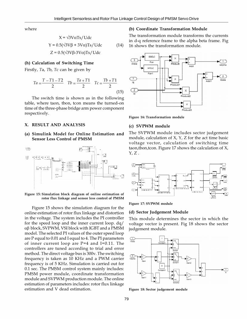
(a) Simulink Model for Online Estimation andSensor Less Control of PMSM
(b) Coordinate Transformation Module
The transformation module transforms the currentsin d-q reference frame to the alpha beta frame. Fig16 shows the transformation module.
Figure 15: Simulation block diagram of online estimation ofrotor flux linkage and sensor less control of PMSM
Figure 15 shows the simulation diagram for theonline estimation of rotor flux linkage and distortionin the voltage. The system includes the PI controllerfor the speed loop and the inner current loop. dq/�� block, SVPWM, VSI block with IGBT and a PMSMmodel. The selected PI values of the outer speed loopare P equal to 0.01 and I equal to 4. The PI parametersof inner current loop are P=4 and I=0.11. Thecontrollers are tuned according to trial and errormethod. The direct voltage bus is 300v. The switchingfrequency is taken as 10 KHz and a PWM carrierfrequency is of 5 KHz. Simulation is carried out for0.1 sec. The PMSM control system mainly includes:PMSM power module, coordinate transformationmodule and SVPWM production module. The onlineestimation of parameters includes: rotor flux linkageestimation and V dead estimation.
Figure 16: Transformation module
(c) SVPWM module
The SVPWM module includes sector judgementmodule, calculation of X, Y, Z for the act time basicvoltage vector, calculation of switching timetaon,tbon,tcon. Figure 17 shows the calculation of X,Y, Z .
Figure 17: SVPWM module
(d) Sector Judgement Module
This module determines the sector in which thevoltage vector is present. Fig 18 shows the sectorjudgement module.
Figure 18: Sector judgement module
S. Radhika and M. Marsalin Beno
80
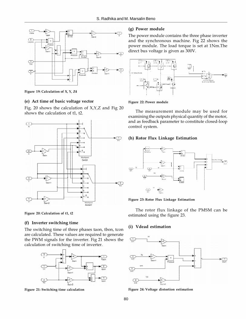
(e) Act time of basic voltage vector
Fig. 20 shows the calculation of X,Y,Z and Fig 20shows the calculation of t1, t2.
(g) Power module
The power module contains the three phase inverterand the synchronous machine. Fig 22 shows thepower module. The load torque is set at 1Nm.Thedirect bus voltage is given as 300V.
Figure 19: Calculation of X, Y, Z4
Figure 20: Calculation of t1, t2
(f) Inverter switching time
The switching time of three phases taon, tbon, tconare calculated. These values are required to generatethe PWM signals for the inverter. Fig 21 shows thecalculation of switching time of inverter.
Figure 21: Switching time calculation
Figure 22: Power module
The measurement module may be used forexamining the outputs physical quantity of the motor,and as feedback parameter to constitute closed-loopcontrol system.
(h) Rotor Flux Linkage Estimation
Figure 23: Rotor Flux Linkage Estimation
The rotor flux linkage of the PMSM can beestimated using the figure 23.
(i) Vdead estimation
Figure 24: Voltage distortion estimation

Intelligent Sensorless and Rotor Flux Linkage Control Design of PMSM Servo Drive
81
Figure24 shows the calculation of the distortedvoltage of the PMSM.
The response of the estimated rotor flux linkageand VSI nonlinearity Vdead can be given by,
Figure 25: Response of rotor flux linkage
The rotor flux linkage of the PMSM can be foundto be settled at 70.7mWb.
Figure 26: Response of Voltage Distortion
XI. CONCLUSION
The Sensorless and Rotor Flux Linkage ControlDesign of PMSM is used for the sensor less fieldoriented control of PMSM using MATLAB/SIMULINK. The results of simulations indicate thatthe system gives desired response. Therefore theSVPWM model is an effective tool for studyingsinusoidal back emf motor drive systems. Thecomplex trigonometric calculations in theconventional SVPWM technique is converted tosimple addition and subtraction logics, by usingintermediate variable and orthogonal decompositionof reference vector. A new scheme for the onlineestimation of PMSM rotor flux linkage and VSI nonlinearity has been proposed which can be used forthe condition monitoring of the rotor permanentmagnet. By this method it is possible to improve theaccuracy, performance and efficiency of the
Sensorless and Rotor Flux Linkage Control Designof PMSM Servo drive.
REFERENCES
[1] M. N.Uddin and M. M. I. Chy, “Online parameter-estimation-based speed control of PM AC motor drivein flux-weakening region,” IEEE Trans. Ind. Appl., vol.44, no. 5, pp. 1486–1494, Sep./Oct. 2010.
[2] K. W. Lee, D. H. Jung, and I. J. Ha, “An onlineidentification method for both stator resistance and back-EMF coefficient of PMSMs without rotationaltransducers,” IEEE Trans. Ind. Electron., vol. 51, no. 2, pp.507–510, Apr. 2004.
[3] Z. Q. Zhu, X. Zhu, and P. D. Sun, “Estimation of windingresistance and PM flux-linkage in brushless AC machinesby reduced-order extended Kalman Filter,” in Proc. IEEEInt. Conf. Netw., Sensing Control, 2007, pp. 740–745.
[4] S. B. Lee, “Closed-loop estimation of permanent magnetsynchronous motor parameters by PI controller gaintuning,” IEEE Trans. EnergyConvers., vol. 21, no. 4, pp.863–870, Dec. 2006.
[5] A. Piippo, M. Hinkkanen, and J. Luomi, “Adaptation ofmotor parameters in sensorless PMSM drives,” IEEE Trans.Ind. Appl., vol. 45, no. 1, pp. 203–212, Jan./Feb. 2009.
[6] S. Morimoto, M. Sanada, and Y. Yakeda, “Mechanicalsensorless drives of IPMSM with online parameteridentification,” IEEE Trans. Ind. Appl., vol. 42, no. 5, pp.1241–1248, Sept./Oct. 2006.
[7] R. Ramakrishnan, R. Islam, M. Islam, and T. Sebastian,“Real time estimation of parameters for controlling andmonitoring,” in Proc. IEEE Int. Elect. Mach. Drives Conf.,Miami, FL, USA, 2009, pp. 1194–1199.
[8] P. J. Zhang, B. Lu, and T. G. Habetler, “A remote andsensorless stator winding resistance estimation methodfor thermal protection of soft-starter-connected inductionmachines,” IEEE Trans. Ind. Electron., vol. 55, no. 10, pp.3611–3618, Oct. 2008.
[9] S. B. Lee and T. G. Habetler, “An online stator windingresistance estimation technique for temperaturemonitoring of line-connected induction machines,” IEEETrans. Ind. Appl., vol. 39, no. 3, pp. 685–694, Mar. 2003.
[10] S. B. Lee and T. G. Habetler, “A remote and sensorlessthermal protection scheme for small line-connected acmachines,” IEEE Trans. Ind. Appl., vol. 39, no. 5, pp. 1323–1332, Sep./Oct. 2008.
[11] S. D. Wilson, P. G. Stewart, and B. P. Taylor, “Methods ofresistance estimation in permanent magnet synchronousmotors for real-time thermal management,” IEEE Trans.Energy Convers., vol. 25, no. 3, pp. 698–707, Sep./Oct. 2008.
[12] S. D. Wilson, G. W. Jewell, and P. G. Stewart, “Resistanceestimation for temperature determination in PMSMsthrough signal injection,” in Proc. IEEE Int. Elect. Mach.Drives Conf., San Antonio, TX, USA, 2005, pp. 735–740.