Intelligent Sensing Framework v. 2.0 Software … Stream Elements ..... 50 A.3.2 Stream APIs..... 50...
78
Freescale Semiconductor Document Number: ISF2P0_KINETIS_SW_REFERENCE_RM REFERENCE MANUAL Rev. 0, 12/2014 Intelligent Sensing Framework v. 2.0 Software Reference Manual for the Kinetis Family of Microcontrollers © 2014 Freescale Semiconductor, Inc.
Transcript of Intelligent Sensing Framework v. 2.0 Software … Stream Elements ..... 50 A.3.2 Stream APIs..... 50...
Freescale Semiconductor Document Number: ISF2P0_KINETIS_SW_REFERENCE_RM REFERENCE MANUAL Rev. 0, 12/2014
Intelligent Sensing Framework v. 2.0 Software Reference Manual for the Kinetis Family of Microcontrollers
© 2014 Freescale Semiconductor, Inc.
Contents 1. About This Document ........................................................................................................................ 4
1.1 Purpose ......................................................................................................................................... 4 1.2 Audience ....................................................................................................................................... 4 1.3 Terminology and Conventions ...................................................................................................... 4
1.3.1 Notational Conventions ................................................................................................................... 7 1.4 References .................................................................................................................................... 7
2. Introduction ........................................................................................................................................ 9 2.1 System Overview .......................................................................................................................... 9 2.2 Development Environment .......................................................................................................... 11
3. Intelligent Sensing Framework ....................................................................................................... 13 3.1 ISF Theory of Operation .............................................................................................................. 13 3.2 ISF Architecture .......................................................................................................................... 14 3.3 Processor Expert Component Architecture ................................................................................. 15 3.4 Core Framework Component Details .......................................................................................... 16
3.4.1 Theory of Operation Overview ....................................................................................................... 16 3.4.2 Framework Overview ..................................................................................................................... 17 3.4.3 Processor Expert Component Overview ....................................................................................... 17 3.4.4 Digital Sensor Abstraction (DSA) .................................................................................................. 18 3.4.5 DSA-Direct Interface ...................................................................................................................... 20 3.4.6 Bus Manager ................................................................................................................................. 21 3.4.7 ISF System Configuration .............................................................................................................. 24 3.4.8 Device Messaging and Protocol Adapters .................................................................................... 25 3.4.9 Host Interface/Command Interpreter ............................................................................................. 28 3.4.10 Power Manager ............................................................................................................................. 40
3.5 Application Support Component Details ..................................................................................... 42 3.5.1 Embedded Application Component ............................................................................................... 42
3.6 MQXLite RTOS ........................................................................................................................... 46 3.6.1 ISF Tasks and Initialization ............................................................................................................ 46
4. Revision History ............................................................................................................................... 48 Appendix A. Streaming Protocol for Host Communication ........................................................... 49
A.1 Introduction ................................................................................................................................. 49 A.2 General Description .................................................................................................................... 49 A.3 Stream Configuration .................................................................................................................. 50 A.3.1 Stream Elements .................................................................................................................. 50 A.3.2 Stream APIs .......................................................................................................................... 50 A.3.2.1 Stream API Functions ........................................................................................................... 51 A.3.2.2 Stream Protocol APIs ............................................................................................................ 51 A.3.2.3 Enable Data Update Command ............................................................................................ 51 A.4 Stream Host Communication ...................................................................................................... 52 A.4.1 Cyclic Redundancy Check (CRC) ......................................................................................... 52 A.4.2 Host Command Packet ......................................................................................................... 53 A.4.3 Command Response Packet ................................................................................................ 53 A.4.4 Update Packet ...................................................................................................................... 54 A.5 Stream Host Commands ............................................................................................................. 56 A.5.1 Command List Summary ...................................................................................................... 56 A.5.2 Command Description .......................................................................................................... 56 A.5.2.1 Reset Command ................................................................................................................... 56 A.5.2.2 Disable Data Update Command ........................................................................................... 57 A.5.2.3 Create Stream Command ..................................................................................................... 58 A.5.2.4 Delete Stream Command ..................................................................................................... 60
2 Intelligent Sensing Framework v. 2.0 Software Reference Manual, Rev. 0, 12/2014 Freescale Semiconductor, Inc.

A.5.2.5 Reset Trigger Command....................................................................................................... 61 A.5.2.6 Enable CRC Command ........................................................................................................ 62 A.5.2.7 Disable CRC Command ........................................................................................................ 63 A.5.2.8 Get Number of Streams Command ...................................................................................... 64 A.5.2.9 Get Trigger State Command ................................................................................................. 65 A.5.2.10 Get Stream Configuration Command .................................................................................... 66 A.5.2.11 Get First Stream ID Command ............................................................................................. 67 A.5.2.12 Get Next Stream ID Command ............................................................................................. 68 A.6 Triggers, Datasets, and Updates ................................................................................................ 69 A.6.1 Dataset ................................................................................................................................. 69 A.6.2 Trigger States ....................................................................................................................... 69 A.6.3 Update Conditions ................................................................................................................ 69 A.6.4 Update Example ................................................................................................................... 70 A.7 Internal Design ............................................................................................................................ 72 A.7.1 Stream Instance .................................................................................................................... 72 A.7.2 Stream Instance Buffer ......................................................................................................... 73 A.7.3 Stream Configuration Buffer ................................................................................................. 74 A.7.4 Stream Instance Linked List Modification ............................................................................. 74
Appendix B. CRC Implementation ................................................................................................... 76
Intelligent Sensing Framework v. 2.0 Software Reference Manual, Rev. 0, 12/2014 3 Freescale Semiconductor, Inc.
About This Document
1. About This Document 1.1 Purpose This reference manual describes the features, architecture, and programming model of the Intelligent Sensing Framework (ISF) embedded middleware, release 2.0. This software is designed to execute on the vast majority of the Kinetis family of microcontrollers supplied by Freescale to easily obtain sensor data. The framework is supported by a set of cooperative Processor Expert (PEx) components that automatically generate the framework code, embedded application code, as well as dependent drivers for a variety of internal hardware components available on Kinetis. Processor Expert technology also generates the MQXLite real-time operating system required by ISF. This document focuses on the core ISF functionality and its use of PEx technology to build custom, embedded sensor applications. Additional information is available in the ISF R2.0 API Reference Manual and the ISF R2.0 Release Notes available at http://www.freescale.com/isf.
1.2 Audience This document is primarily for system architects and software application developers currently using or considering using the ISF R2.0 middleware on the Kinetis family of microcontrollers as the basis for an intelligent sensor system in an end-user product.
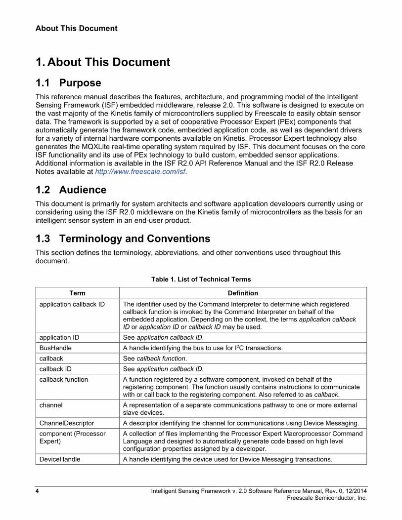
1.3 Terminology and Conventions This section defines the terminology, abbreviations, and other conventions used throughout this document.
Table 1. List of Technical Terms
Term Definition application callback ID The identifier used by the Command Interpreter to determine which registered
callback function is invoked by the Command Interpreter on behalf of the embedded application. Depending on the context, the terms application callback ID or application ID or callback ID may be used.
application ID See application callback ID. BusHandle A handle identifying the bus to use for I2C transactions. callback See callback function. callback ID See application callback ID. callback function A function registered by a software component, invoked on behalf of the
registering component. The function usually contains instructions to communicate with or call back to the registering component. Also referred to as callback.
channel A representation of a separate communications pathway to one or more external slave devices.
ChannelDescriptor A descriptor identifying the channel for communications using Device Messaging. component (Processor Expert)
A collection of files implementing the Processor Expert Macroprocessor Command Language and designed to automatically generate code based on high level configuration properties assigned by a developer.
DeviceHandle A handle identifying the device used for Device Messaging transactions.
4 Intelligent Sensing Framework v. 2.0 Software Reference Manual, Rev. 0, 12/2014 Freescale Semiconductor, Inc.
About This Document
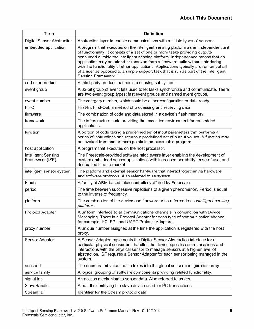
Term Definition Digital Sensor Abstraction Abstraction layer to enable communications with multiple types of sensors. embedded application A program that executes on the intelligent sensing platform as an independent unit
of functionality. It consists of a set of one or more tasks providing outputs consumed outside the intelligent sensing platform. Independence means that an application may be added or removed from a firmware build without interfering with the functionality of other applications. Applications typically are run on behalf of a user as opposed to a simple support task that is run as part of the Intelligent Sensing Framework.
end-user product A third-party product that hosts a sensing subsystem. event group A 32-bit group of event bits used to let tasks synchronize and communicate. There
are two event group types: fast event groups and named event groups. event number The category number, which could be either configuration or data ready. FIFO First-In, First-Out; a method of processing and retrieving data firmware The combination of code and data stored in a device’s flash memory. framework The infrastructure code providing the execution environment for embedded
applications. function A portion of code taking a predefined set of input parameters that performs a
series of instructions and returns a predefined set of output values. A function may be invoked from one or more points in an executable program.
host application A program that executes on the host processor. Intelligent Sensing Framework (ISF)
The Freescale-provided software middleware layer enabling the development of custom embedded sensor applications with increased portability, ease-of-use, and decreased time-to-market.
intelligent sensor system The platform and external sensor hardware that interact together via hardware and software protocols. Also referred to as system.
Kinetis A family of ARM-based microcontrollers offered by Freescale. period The time between successive repetitions of a given phenomenon. Period is equal
to the inverse of frequency. platform The combination of the device and firmware. Also referred to as intelligent sensing
platform. Protocol Adapter A uniform interface to all communications channels in conjunction with Device
Messaging. There is a Protocol Adapter for each type of communication channel, for example: I2C, SPI, and UART Protocol Adapters.
proxy number A unique number assigned at the time the application is registered with the host proxy.
Sensor Adapter A Sensor Adapter implements the Digital Sensor Abstraction interface for a particular physical sensor and handles the device-specific communications and interactions with the physical sensor to manage sensors at a higher level of abstraction. ISF requires a Sensor Adapter for each sensor being managed in the system.
sensor ID The enumerated value that indexes into the global sensor configuration array. service family A logical grouping of software components providing related functionality. signal tap An access mechanism to sensor data. Also referred to as tap. SlaveHandle A handle identifying the slave device used for I2C transactions. Stream ID Identifier for the Stream protocol data
Intelligent Sensing Framework v. 2.0 Software Reference Manual, Rev. 0, 12/2014 5 Freescale Semiconductor, Inc.
About This Document
Term Definition system The platform and external sensor hardware that interact together via hardware
and software protocols. Also referred to as intelligent sensor system. tap An access mechanism to sensor data. Also referred to as signal tap. task An operating entity within the Intelligent Sensing Framework (ISF) scheduled to
execute by the Freescale MQXLite™ RTOS. A task may entail the execution of one or more functions.
transport Communications mechanism. Examples: I2C, SPI, Bluetooth©, Ethernet, and USB
token Result of a successful callback function registration with the bus manager used in subsequent bus management calls to refer to a registered callback function.
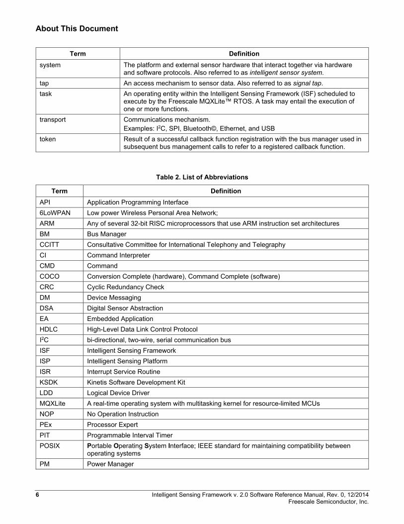
Table 2. List of Abbreviations
Term Definition API Application Programming Interface 6LoWPAN Low power Wireless Personal Area Network; ARM Any of several 32-bit RISC microprocessors that use ARM instruction set architectures BM Bus Manager CCITT Consultative Committee for International Telephony and Telegraphy CI Command Interpreter CMD Command COCO Conversion Complete (hardware), Command Complete (software) CRC Cyclic Redundancy Check DM Device Messaging DSA Digital Sensor Abstraction EA Embedded Application HDLC High-Level Data Link Control Protocol I2C bi-directional, two-wire, serial communication bus ISF Intelligent Sensing Framework ISP Intelligent Sensing Platform ISR Interrupt Service Routine KSDK Kinetis Software Development Kit LDD Logical Device Driver MQXLite A real-time operating system with multitasking kernel for resource-limited MCUs NOP No Operation Instruction PEx Processor Expert PIT Programmable Interval Timer POSIX Portable Operating System Interface; IEEE standard for maintaining compatibility between
operating systems PM Power Manager
6 Intelligent Sensing Framework v. 2.0 Software Reference Manual, Rev. 0, 12/2014 Freescale Semiconductor, Inc.
About This Document
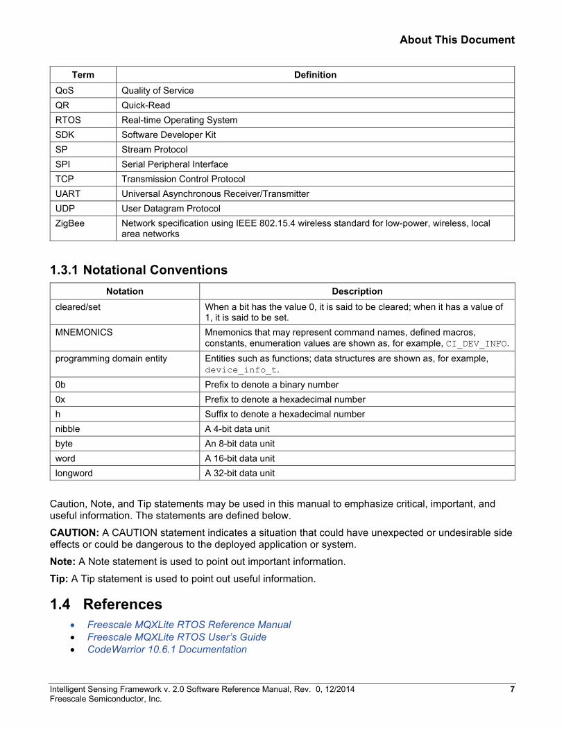
Term Definition QoS Quality of Service QR Quick-Read RTOS Real-time Operating System SDK Software Developer Kit SP Stream Protocol SPI Serial Peripheral Interface TCP Transmission Control Protocol UART Universal Asynchronous Receiver/Transmitter UDP User Datagram Protocol ZigBee Network specification using IEEE 802.15.4 wireless standard for low-power, wireless, local
area networks
1.3.1 Notational Conventions Notation Description
cleared/set When a bit has the value 0, it is said to be cleared; when it has a value of 1, it is said to be set.
MNEMONICS Mnemonics that may represent command names, defined macros, constants, enumeration values are shown as, for example, CI_DEV_INFO.
programming domain entity Entities such as functions; data structures are shown as, for example, device_info_t.
0b Prefix to denote a binary number 0x Prefix to denote a hexadecimal number h Suffix to denote a hexadecimal number nibble A 4-bit data unit byte An 8-bit data unit word A 16-bit data unit longword A 32-bit data unit
Caution, Note, and Tip statements may be used in this manual to emphasize critical, important, and useful information. The statements are defined below.
CAUTION: A CAUTION statement indicates a situation that could have unexpected or undesirable side effects or could be dangerous to the deployed application or system.
Note: A Note statement is used to point out important information.
Tip: A Tip statement is used to point out useful information.
1.4 References • Freescale MQXLite RTOS Reference Manual • Freescale MQXLite RTOS User’s Guide • CodeWarrior 10.6.1 Documentation
Intelligent Sensing Framework v. 2.0 Software Reference Manual, Rev. 0, 12/2014 7 Freescale Semiconductor, Inc.

About This Document
• Kinetis Design Studio 1.1.1 Documentation • Processor Expert Documentation • New Sensor Toolbox Documentation • Kinetis Software Design Kit Documentation • Freescale Freedom Development Board Platform web site • FRDM-FXS-MULTI-B Documentation • FRDM-KL25Z Documentation • FRDM-KL26Z Documentation • FRDM-K64F Documentation
8 Intelligent Sensing Framework v. 2.0 Software Reference Manual, Rev. 0, 12/2014 Freescale Semiconductor, Inc.
Introduction
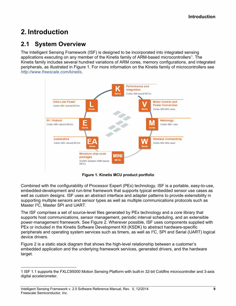
2. Introduction 2.1 System Overview The Intelligent Sensing Framework (ISF) is designed to be incorporated into integrated sensing applications executing on any member of the Kinetis family of ARM-based microcontrollers1. The Kinetis family includes several hundred variations of ARM cores, memory configurations, and integrated peripherals, as illustrated in Figure 1. For more information on the Kinetis family of microcontrollers see http://www.freescale.com/kinetis.
Figure 1. Kinetis MCU product portfolio
Combined with the configurability of Processor Expert (PEx) technology, ISF is a portable, easy-to-use, embedded-development and run-time framework that supports typical embedded sensor use cases as well as custom designs. ISF uses an abstract interface and adapter patterns to provide extensibility in supporting multiple sensors and sensor types as well as multiple communications protocols such as Master I2C, Master SPI and UART.
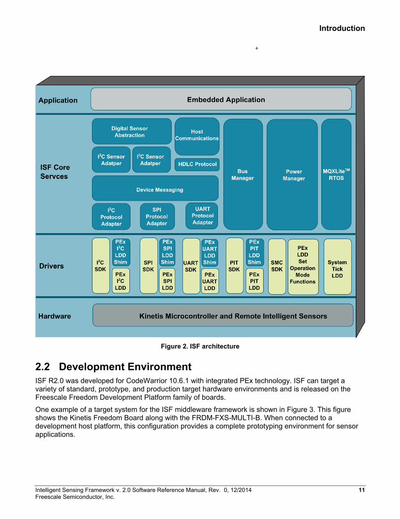
The ISF comprises a set of source-level files generated by PEx technology and a core library that supports host communications, sensor management, periodic interval scheduling, and an extensible power-management framework. See Figure 2. Wherever possible, ISF uses components supplied with PEx or included in the Kinetis Software Development Kit (KSDK) to abstract hardware-specific peripherals and operating system services such as timers, as well as I2C, SPI and Serial (UART) logical device drivers.
Figure 2 is a static stack diagram that shows the high-level relationship between a customer’s embedded application and the underlying framework services, generated drivers, and the hardware target.
1 ISF 1.1 supports the FXLC95000 Motion Sensing Platform with built-in 32-bit Coldfire microcontroller and 3-axis digital accelerometer.
Intelligent Sensing Framework v. 2.0 Software Reference Manual, Rev. 0, 12/2014 9 Freescale Semiconductor, Inc.

Introduction
The ISF system components that provide the functionality required for developing sensor applications, are as follows:
• Device hardware: The Kinetis family of microcontrollers provide several hundred different individual configurations of ARM cores, memory, and integrated peripherals. ISF is designed to run on the vast majority of the Kinetis family. ISF depends on a very small subset of the integrated hardware peripherals including a System Tick counter, a Programmable Interval Timer (PIT), any of the I2C, SPI, or UART/Serial interfaces (optional), and various interrupt/GPIO pins. For analog sensors, an Analog-to-Digital Converter can be used to acquire sensor outputs.
• ISF: The Intelligent Sensor Framework (ISF) provides embedded applications the capability to subscribe to external sensor data and read such data at various rates. It also supports communication between the host processor and the application via a UART/Serial interface. ISF allows the Kinetis microcontroller to act as a sensor hub for external sensors and to manage that data for the host processor.
• MQXLite™: Freescale MQXLite Real-Time Operating System (RTOS) is a run-time library of functions that provides real-time, multitasking capabilities to embedded applications. MQXLite operates as a priority-preemptive operating system. The main features are its scalable size, component-oriented architecture, and ease of use.
10 Intelligent Sensing Framework v. 2.0 Software Reference Manual, Rev. 0, 12/2014 Freescale Semiconductor, Inc.
Introduction
Figure 2. ISF architecture
2.2 Development Environment ISF R2.0 was developed for CodeWarrior 10.6.1 with integrated PEx technology. ISF can target a variety of standard, prototype, and production target hardware environments and is released on the Freescale Freedom Development Platform family of boards.
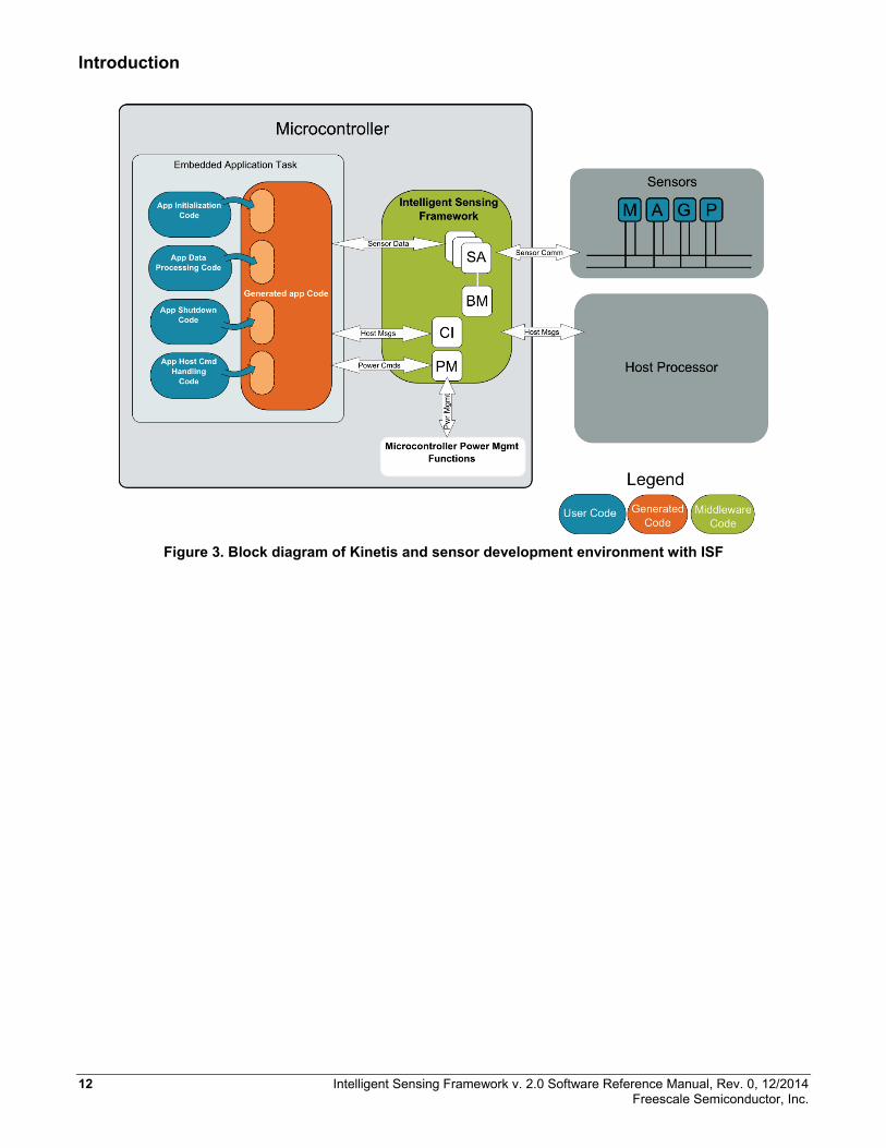
One example of a target system for the ISF middleware framework is shown in Figure 3. This figure shows the Kinetis Freedom Board along with the FRDM-FXS-MULTI-B. When connected to a development host platform, this configuration provides a complete prototyping environment for sensor applications.
Intelligent Sensing Framework v. 2.0 Software Reference Manual, Rev. 0, 12/2014 11 Freescale Semiconductor, Inc.
Introduction
Figure 3. Block diagram of Kinetis and sensor development environment with ISF
12 Intelligent Sensing Framework v. 2.0 Software Reference Manual, Rev. 0, 12/2014 Freescale Semiconductor, Inc.
Intelligent Sensing Framework
3. Intelligent Sensing Framework This section describes the Intelligent Sensing Framework architecture, the Process Expert Technology components that support it, and a high level description of the library level services. This section also describes the details of the default Embedded Application generated by its own PEx component. Finally, it describes the usage of the MQXLite RTOS also generated within the PEx development environments.
The ISF uses a combination of a static library instantiated into the project along with a set of PEx components that automatically generate the remaining ISF Core code, Communication Channels, and Sensor Interfaces based on high-level configuration properties. Wherever possible, the ISF conforms to existing PEx components and KSDK driver interfaces create driver level software for the Kinetis microcontrollers.
3.1 ISF Theory of Operation The ISF R2.0 is designed to be used throughout any product development cycle requiring access to real-time sensor data and/or processing by an intermediate microcontroller acting as both a sensor hub and an application layer. The microcontroller executes the ISF embedded middleware along with a real-time operating system (currently MQXLite) and application-level code supplied by the embedded application developer. ISF can support a variety of products with a wide range of resources and configurations. The framework is tested and released to run on Freescale’s line of development boards called Freedom Development Platforms. As the developer’s project progresses, the framework can be seamlessly ported to any selected Kinetis microcontroller, with minimal effort. While every product development effort is unique, the usage of the ISF R2.0 Embedded Middleware supports three general use cases.
In the earliest stage of product development, exploration of the capabilities of a variety of microcontrollers and sensors is of the most importance to developers. ISF with PEx allows the developer to quickly explore the capabilities of all supported sensors, using the PEx components to modify the operation of individual sensors at a register level. ISF allows the application developer to receive raw sensor output to the host without writing a single line of code for the embedded platform. This stage is also an ideal period to assess the capabilities of the ISF middleware for fit in the final product design.
During the prototyping stage of product development, the target environment is rendered using as much off-the-shelf software and hardware as possible in order to reduce the overall development time. One approach is to integrate Freescale’s Freedom boards into the prototype using the Arduino-compatible interface connectors as a bridge into the prototype platform. This approach allows the developer to leverage the ISF to the maximum extent possible, and to develop software solely at the application layer, during the prototyping phase. Typical goals include reduced system cost, leveraging memory and peripheral options, CPU speed, and interface choices can be easily evaluated using this approach.
It is during the final product design stage when the real advantages of using the ISF become apparent. An application specific to the prototype system can be brought into the production product without any changes necessary, since the ISF eliminates any porting complexity at the system configuration level. The PEx components can be reconfigured to handle modifications in the system design including MCU and sensors selection, interface changes, and pin multiplexing changes. In addition, new interfaces or peripherals can be added to the system and accessed immediately at the application layer, with minimal additional rework.
Intelligent Sensing Framework v. 2.0 Software Reference Manual, Rev. 0, 12/2014 13 Freescale Semiconductor, Inc.
Intelligent Sensing Framework
3.2 ISF Architecture The ISF R2.0 architecture has been designed to provide rapid generation of embedded application code and customized middleware configurations, based on a set of high-level configuration properties applied to a set of PEx software components. These Processor Expert components relate to each other based on a specific hierarchy. This hierarchy aids the embedded application developer by eliminating omissions that can lead to run-time errors in the system. In addition, PEx technology can error-check and cross-check property settings between the components to guarantee consistency ahead of actually building the application.
The services included in the ISF library are only brought into the application as needed. This allows the user to tailor the features of ISF to their specific application and resource environment.
ISF R2.0 is generated by PEx technology, based on the configuration established by the developer. The software is constructed in layers and uses many of the existing PEx Logical Device Drivers (LDD) and Kinetis SDK Libraries, as is practical. The bottom layer of this hierarchy is the configuration of Kinetis microcontroller, communications interfaces, and remote sensors desired by the application developer. The Driver layer consists mostly of existing PEx components (LDDs and KSDK) that provide the driver-level interfaces to internal hardware peripherals, inside the Kinetis microcontroller. The ISF Services layer is the set of PEx-generated software that provides the services described in the following sections.
Uniform interfaces allow applications to access physical data, measured by the remote sensors. The ISF Core library is acting as a server provides sensor data to registered applications, acting as clients needing that sensor data. The sensor data is applied to the application at various rates and formats.
The Host Communications service provides the ability to pass data into and out of the Intelligent Sensing Framework via the UART/Serial interface. The Host Interface supports a proprietary, command/response protocol with a set of pre-defined commands. The Host service enables the embedded application developer to extend the command set. This service also provides a flexible, asynchronous data streaming protocol.
The Device Messaging and Protocol Adapters services provide a uniform interface to all communications channels (I2C, SPI, UART). The Protocol Adaptor layer for each underlying protocol allows the service to run on top of either the PEx LDD or the KSDK drivers, without modification.
The Power Manager service provides a uniform model for the microcontroller, integrated peripherals, and remote sensors, power management, based on a developer-extensible set of modes.
The MQXLite RTOS is generated at a source level through its own PEx component. It provides lightweight, real-time scheduling, intertask events, resource semaphores, interrupts, stack and heap management.
Software components from the above-mentioned service families are packaged into libraries that target the various ARM core types in the Kinetis family. The ISF Core library packages several software components to form the base set of functionality. Additional functionality is provided by ISF PEx components that generate source code based on the desired developer configuration of each of the component’s properties.
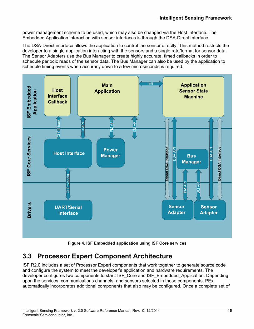
The ISF Embedded Application relies on the ISF Core Services for its operation. The Embedded Application is either partially generated by PEx or fully written by the developer. Figure 4 shows a high-level view of the services required by the application.
The application statically registers a callback function with the Host Interface, at compile time. The Host Interface uses the callback to execute commands addressed to the application. The application also uses the Host Interface to send asynchronous packets to the Host. The application establishes the
14 Intelligent Sensing Framework v. 2.0 Software Reference Manual, Rev. 0, 12/2014 Freescale Semiconductor, Inc.
Intelligent Sensing Framework
power management scheme to be used, which may also be changed via the Host Interface. The Embedded Application interaction with sensor interfaces is through the DSA-Direct Interface.
The DSA-Direct interface allows the application to control the sensor directly. This method restricts the developer to a single application interacting with the sensors and a single rate/format for sensor data. The Sensor Adapters use the Bus Manager to create highly accurate, timed callbacks in order to schedule periodic reads of the sensor data. The Bus Manager can also be used by the application to schedule timing events when accuracy down to a few microseconds is required.
Figure 4. ISF Embedded application using ISF Core services
3.3 Processor Expert Component Architecture ISF R2.0 includes a set of Processor Expert components that work together to generate source code and configure the system to meet the developer’s application and hardware requirements. The developer configures two components to start: ISF_Core and ISF_Embedded_Application. Depending upon the services, communications channels, and sensors selected in these components, PEx automatically incorporates additional components that also may be configured. Once a complete set of
Intelligent Sensing Framework v. 2.0 Software Reference Manual, Rev. 0, 12/2014 15 Freescale Semiconductor, Inc.

Intelligent Sensing Framework
components is instantiated in the project, code generation can be initiated. The following sections explain the ISF PEx components in more detail.
The ISF_Core component allows the developer to include from the ISF Core Library (Bus Manager, Power Manager and Command Interpreter) the desired optional services for the specific Cortex family, for example, Cortex M0+, M4, M4F. In resource-constrained systems, some or all of these services may be excluded in order to save memory or processing cycles. ISF_Core also provides the developer with the ability to select from a list of supported sensors, the necessary remote sensors to be included in the system.
The ISF_Embedded_Application is an optional component that provides the developer with a pre-compiled structure to extract and process raw sensor data from a set of sensors. The component includes a list of subscriptions to types of sensors including accelerometers, magnetometers, gyroscopes, pressure and temperature sensors. The component displays a list of sensor interfaces that match the selected type and correspond to physical sensors in the system. In addition, the ISF_Embedded_Application component allows the developer to configure the Host Interface and extend the default set of the host commands.
The ISF_Protocol_Adapter component provides a collection of interface adapters (I2C, SPI, UART) along with the Device Messaging services needed. The component automatically configures the desired protocol and instantiates any underlying LDD or KSDK drivers. This component is not selected by the developer directly, but is incorporated, based on the Sensor and Host Interface configuration in ISF_Core.
ISF_Sensor_Adapter_Interface is a collection of components that select individual sensor interface components implemented in the ISF system. The component provides for grouping of sensors based on function and type. It also generates the sensor-specific configuration of instantiated sensors in the system. Finally, it generates the global list of sensors used during run-time to access and control sensors.
The ISF_Bus_Manager component allows the developer to select the specific PIT hardware to be used for the application callback, event timing.
The ISF_Power_Manager component generates a framework for generic power management with the ability for the developer to customize both the levels and the modes of operation, as well as the actual behaviors of individual Kinetis and sensor components.
3.4 Core Framework Component Details 3.4.1 Theory of Operation Overview ISF is separated into the ISF Core component and the Embedded Application component. While these components are designed to work together, the ISF Core can be used as a stand-alone to create the framework, sensor interfaces, and communication channels. ISF Core can then be used with a freeform application, via the exposed run-time APIs.
After creating a project with PEx technology, the developer can import the ISF_Core component from the PEx component library. This component allows the developer to select the core features of ISF to be included. The ISF_Core automatically instantiates various other components, based on the developer-selected features. In a fully configured system, the ISF_Core automatically creates an ISF_Bus_Manager, ISF_Protocol_Adapter, and several MQXLite tasks.
Once the features of the ISF Core have been selected, the developer can then select the sensors to be included in the system. Each sensor has its own, specific, PEx component. These allow the developer
16 Intelligent Sensing Framework v. 2.0 Software Reference Manual, Rev. 0, 12/2014 Freescale Semiconductor, Inc.
Intelligent Sensing Framework
to select or create the desired communication channel interface and to set the sensor-specific, register-level configuration, if necessary.
After the ISF_Core component has been configured, the developer may use the code generation feature to create the ISF framework.
3.4.2 Framework Overview The ISF is a combination of autogenerated code and linked libraries. The libraries implement the internal features of the Bus Manager, Command Interpreter (Host Interface), and Power Manager. The library is integrated into the ISF_Core component and generated as an object file during the code generation step. When the resulting application is compiled and linked, only the necessary functions in the library are brought into the executable file.
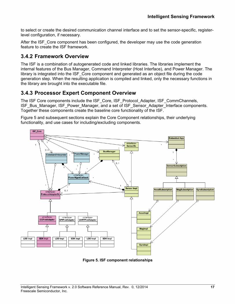
3.4.3 Processor Expert Component Overview The ISF Core components include the ISF_Core, ISF_Protocol_Adapter, ISF_CommChannels, ISF_Bus_Manager, ISF_Power_Manager, and a set of ISF_Sensor_Adapter_Interface components. Together these components create the baseline core functionality of the ISF.
Figure 5 and subsequent sections explain the Core Component relationships, their underlying functionality, and use cases for including/excluding components.
Figure 5. ISF component relationships
Intelligent Sensing Framework v. 2.0 Software Reference Manual, Rev. 0, 12/2014 17 Freescale Semiconductor, Inc.
Intelligent Sensing Framework
3.4.4 Digital Sensor Abstraction (DSA) 3.4.4.1 Theory of Operation The Digital Sensor Abstraction (DSA) is used to expose a standard interface to sensor command and control functionality while maintaining a sensor-specific implementation. The DSA defines interfaces to initialize, configure, start, stop, and shutdown a sensor, to validate sensor settings and to convert native sensor sample data to standard sensor types.
The set of functions implementing these functions for a given sensor is known as a sensor adapter. The architecture enables the embedded application developer to write new sensor adapters and to associate these adapters with existing or new sensors connected to the platform.
The list of the sensors available is maintained in a global list. This list associates each instance of a sensor in the system with a system-unique Sensor ID, a sensor adapter, and other specific instance data needed to uniquely address the sensor. The API enables its users to refer to sensors via their assigned Sensor ID when subscribing. Internally, the provided Sensor ID is used to either lookup the sensor configuration information contained in the System Sensor Configuration list or to invoke the appropriate sensor adapter functions.
The Digital Sensor Abstraction (DSA) adapter functions to interact and manage its sensors. The sensor adapter functions are designed to allow multiple sensor instances of a particular type to all reference the same sensor adapter. This means that instance data specific to a particular sensor must be kept separate from the adapter code and passed into each adapter function through a reference pointer. Thus, the adapter may be thought of as a set of class methods, each taking an explicit this pointer in addition to any other arguments pertinent to the specific function.
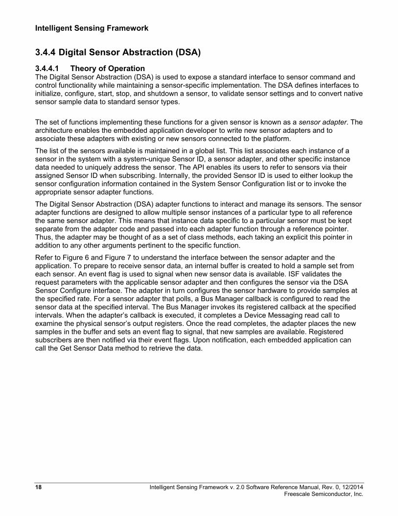
Refer to Figure 6 and Figure 7 to understand the interface between the sensor adapter and the application. To prepare to receive sensor data, an internal buffer is created to hold a sample set from each sensor. An event flag is used to signal when new sensor data is available. ISF validates the request parameters with the applicable sensor adapter and then configures the sensor via the DSA Sensor Configure interface. The adapter in turn configures the sensor hardware to provide samples at the specified rate. For a sensor adapter that polls, a Bus Manager callback is configured to read the sensor data at the specified interval. The Bus Manager invokes its registered callback at the specified intervals. When the adapter’s callback is executed, it completes a Device Messaging read call to examine the physical sensor’s output registers. Once the read completes, the adapter places the new samples in the buffer and sets an event flag to signal, that new samples are available. Registered subscribers are then notified via their event flags. Upon notification, each embedded application can call the Get Sensor Data method to retrieve the data.
18 Intelligent Sensing Framework v. 2.0 Software Reference Manual, Rev. 0, 12/2014 Freescale Semiconductor, Inc.
Intelligent Sensing Framework
Figure 6. Digital Sensor Abstraction calling sequence
3.4.4.2 DSA Module Design The majority of the sensor-specific software used by ISF R2.0 is included in modules that conform to the DSA interface and implement a reentrant interface to a specific sensor. Besides implementing the sensor interface abstraction, each module also uses register-level configuration information, created by its associated PEx component, to configure the underlying sensor. The sensor-specific module is included only once in the project, based on the selection of the sensor in the ISF_Core component’s System Sensor Configuration.
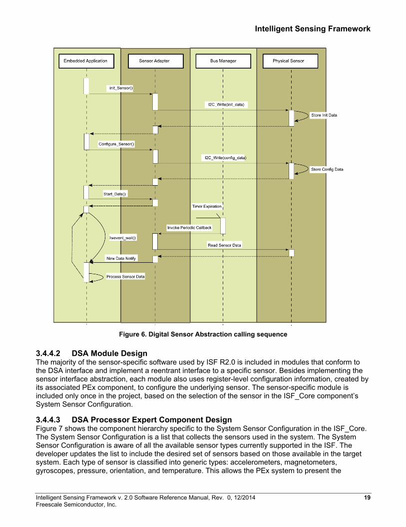
3.4.4.3 DSA Processor Expert Component Design Figure 7 shows the component hierarchy specific to the System Sensor Configuration in the ISF_Core. The System Sensor Configuration is a list that collects the sensors used in the system. The System Sensor Configuration is aware of all the available sensor types currently supported in the ISF. The developer updates the list to include the desired set of sensors based on those available in the target system. Each type of sensor is classified into generic types: accelerometers, magnetometers, gyroscopes, pressure, orientation, and temperature. This allows the PEx system to present the
Intelligent Sensing Framework v. 2.0 Software Reference Manual, Rev. 0, 12/2014 19 Freescale Semiconductor, Inc.
Intelligent Sensing Framework
embedded application with alternative sensors that are interface-equivalent at the application level and can be integrated without changes to the application.
As is shown in Figure 7, the specific sensor instance is created by the sensor-specific components for example, ISF_Sensor_MMA8652_Interface. These components generate the static configuration data structures for the desired instance of the sensor. They further define the DSA interface for this sensor instance and map the function calls to the sensor specific module’s functions.
The sensor-specific components also include properties that expose the register-level interfaces to the sensor. This feature allows advanced embedded application developers to modify specific features of a sensor instance statically if desired. Default values for all of these properties are supplied and conform to the sensor default values as specified in their Data Sheets.
Figure 7. ISF R2.0 component hierarchy
3.4.5 DSA-Direct Interface 3.4.5.1 Theory of Operation As described in Section 3.4.4.1, applications make use of raw sensor data. In this case, the ISF supplies a DSA-Direct interface for this purpose.
3.4.5.2 DSA-Direct Module Design The DSA-Direct interface is a functional API that provides initialization, configuration, operational control (start/stop) and sensor data conversion routines. The DSA-Direct function calls perform error checking and global data structure updates. It makes direct calls to the corresponding sensor’s DSA interface functions via the adapter function call interface.
3.4.5.3 Generic Sensor Types and Standard Sensor Data Types ISF R2.0 supports Generic Sensor Types and Standard Sensor Data Types as part of the subscription interface to the sensor. This step towards standardization for the sensor interfaces continues to preserve the option of the native sensor data format.
The ISF supports the following types of sensors:
20 Intelligent Sensing Framework v. 2.0 Software Reference Manual, Rev. 0, 12/2014 Freescale Semiconductor, Inc.

Intelligent Sensing Framework
• Accelerometer (1 to 3 Axes) • Magnetometer (1 to 3 Axes) • Gyroscope (1 to 3 Axes) • Orientation • Inclinometer (1 to 3 Axes) • Thermometer • Pressure Sensor (Altimeter, Barometer, Absolute, Relative) • Significant Motion Sensor
Each sensor supports its native output data format along with converted sensor output fixed-point and floating-point formats in standard engineering units for example, magnetic field strength in microTeslas (µT) for magnetometers).
Each Sensor Adapter includes a conversion routine that scales the native format to the desired standard format based on the application subscription parameters: resultType and resultFormat.
3.4.6 Bus Manager 3.4.6.1 Theory of Operation The ISF_Bus_Manager (BM) provides a highly accurate, timed, callback service with a resolution down to 1 μsec. Embedded Applications or sensor adapters may use the BM services to create periodic callbacks at the specified interval2.
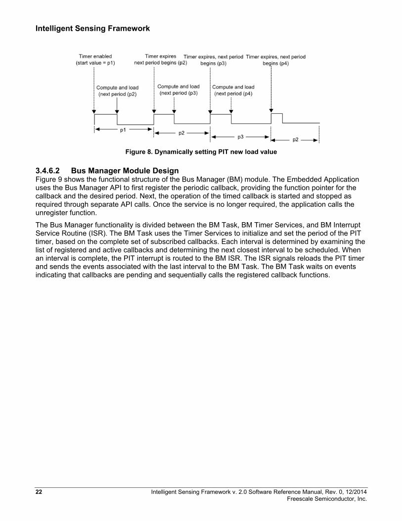
The Bus Manager uses one of the Periodic Interval Timers (PIT) internal to the Kinetis microcontroller. The PIT was chosen because its interval may be loaded while the previous interval is executing on the timer. Figure 8 shows the behavior of the PIT when the PIT_LDVAL register is modified while the timer is actively running. The PIT is a countdown timer that generates an interrupt as the count reaches zero. A value loaded into the PIT_LDVAL register takes effect at the next interrupt (zero). The BM design relies on the ability to keep the PIT pipeline constantly fed with the next expected interval.
While the actual timed interval is very accurate, the MQXLite RTOS interrupt handling and ISF_Bus_Manager service itself introduces some delay between when the timer actually fires and when the registered callback is invoked. Jitter between successive callback invocations is generally low but can be affected by other interrupts including processing of messages from the host as well as preemption by higher-priority tasks in the system. Applications requiring extreme accuracy must therefore use direct interrupts and/or DMA services.
2 The Bus Manager services may also be used to create “one-shot” timing events. In this scenario, the bm_start() function may be called to schedule a callback. Inside the callback, the user needs to call bm_stop() in order to terminate the callback after a single execution.
Intelligent Sensing Framework v. 2.0 Software Reference Manual, Rev. 0, 12/2014 21 Freescale Semiconductor, Inc.
Intelligent Sensing Framework
Figure 8. Dynamically setting PIT new load value
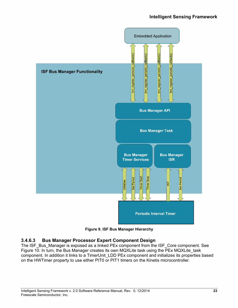
3.4.6.2 Bus Manager Module Design Figure 9 shows the functional structure of the Bus Manager (BM) module. The Embedded Application uses the Bus Manager API to first register the periodic callback, providing the function pointer for the callback and the desired period. Next, the operation of the timed callback is started and stopped as required through separate API calls. Once the service is no longer required, the application calls the unregister function.
The Bus Manager functionality is divided between the BM Task, BM Timer Services, and BM Interrupt Service Routine (ISR). The BM Task uses the Timer Services to initialize and set the period of the PIT timer, based on the complete set of subscribed callbacks. Each interval is determined by examining the list of registered and active callbacks and determining the next closest interval to be scheduled. When an interval is complete, the PIT interrupt is routed to the BM ISR. The ISR signals reloads the PIT timer and sends the events associated with the last interval to the BM Task. The BM Task waits on events indicating that callbacks are pending and sequentially calls the registered callback functions.
22 Intelligent Sensing Framework v. 2.0 Software Reference Manual, Rev. 0, 12/2014 Freescale Semiconductor, Inc.
Intelligent Sensing Framework
Figure 9. ISF Bus Manager Hierarchy
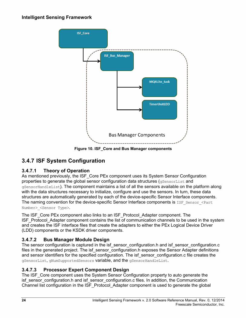
3.4.6.3 Bus Manager Processor Expert Component Design The ISF_Bus_Manager is exposed as a linked PEx component from the ISF_Core component. See Figure 10. In turn, the Bus Manager creates its own MQXLite task using the PEx MQXLite_task component. In addition it links to a TimerUnit_LDD PEx component and initializes its properties based on the HWTimer property to use either PIT0 or PIT1 timers on the Kinetis microcontroller.
Intelligent Sensing Framework v. 2.0 Software Reference Manual, Rev. 0, 12/2014 23 Freescale Semiconductor, Inc.
Intelligent Sensing Framework
Figure 10. ISF_Core and Bus Manager components
3.4.7 ISF System Configuration 3.4.7.1 Theory of Operation As mentioned previously, the ISF_Core PEx component uses its System Sensor Configuration properties to generate the global sensor configuration data structures (gSensorList and gSensorHandleList). The component maintains a list of all the sensors available on the platform along with the data structures necessary to initialize, configure and use the sensors. In turn, these data structures are automatically generated by each of the device-specific Sensor Interface components. The naming convention for the device-specific Sensor Interface components is ISF_Sensor_<Part Number>_<Sensor Type>.
The ISF_Core PEx component also links to an ISF_Protocol_Adapter component. The ISF_Protocol_Adapter component contains the list of communication channels to be used in the system and creates the ISF interface files that create the adapters to either the PEx Logical Device Driver (LDD) components or the KSDK driver components.
3.4.7.2 Bus Manager Module Design The sensor configuration is captured in the isf_sensor_configuration.h and isf_sensor_configuration.c files in the generated project. The isf_sensor_configuration.h exposes the Sensor Adapter definitions and sensor identifiers for the specified configuration. The isf_sensor_configuration.c file creates the gSensorList, gNumSupportedSensors variable, and the gSensorHandleList.
3.4.7.3 Processor Expert Component Design The ISF_Core component uses the System Sensor Configuration property to auto generate the isf_sensor_configuration.h and isf_sensor_configuration.c files. In addition, the Communication Channel list configuration in the ISF_Protocol_Adapter component is used to generate the global
24 Intelligent Sensing Framework v. 2.0 Software Reference Manual, Rev. 0, 12/2014 Freescale Semiconductor, Inc.
Intelligent Sensing Framework
COMM_CHANNEL_<Channel> list, the gSys_ConfiguredChannelList data structure, as well as the individual channel-specific, global initialization data structures.
3.4.8 Device Messaging and Protocol Adapters 3.4.8.1 Theory of Operation Device Messaging is intimately tied to the individual protocol adapters for I2C, SPI, and UART/Serial interfaces. Device Messaging exposes consistent user-level APIs for communicating with external devices. The goal of Device Messaging is to abstract the communications protocol to provide a unified interface for communications, regardless of the underlying transport method used.
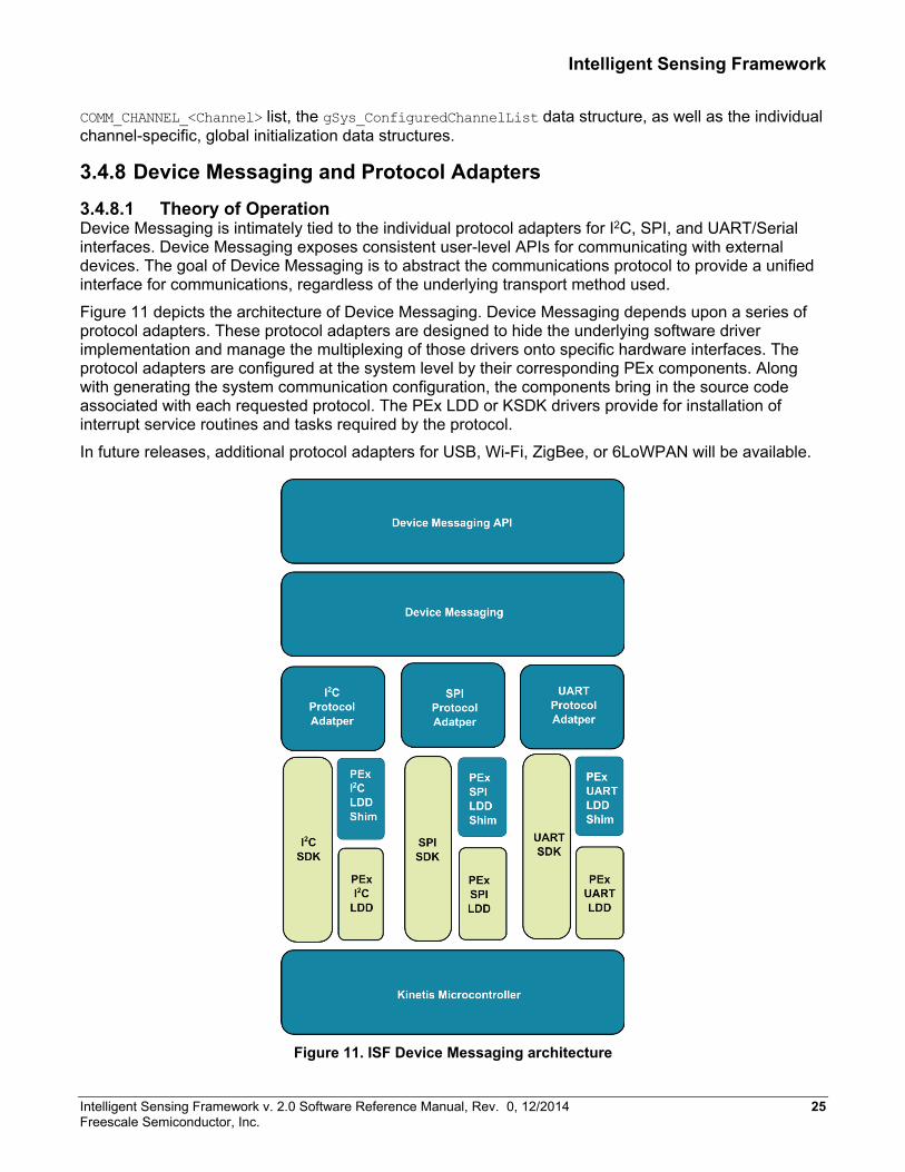
Figure 11 depicts the architecture of Device Messaging. Device Messaging depends upon a series of protocol adapters. These protocol adapters are designed to hide the underlying software driver implementation and manage the multiplexing of those drivers onto specific hardware interfaces. The protocol adapters are configured at the system level by their corresponding PEx components. Along with generating the system communication configuration, the components bring in the source code associated with each requested protocol. The PEx LDD or KSDK drivers provide for installation of interrupt service routines and tasks required by the protocol.
In future releases, additional protocol adapters for USB, Wi-Fi, ZigBee, or 6LoWPAN will be available.
Figure 11. ISF Device Messaging architecture
Intelligent Sensing Framework v. 2.0 Software Reference Manual, Rev. 0, 12/2014 25 Freescale Semiconductor, Inc.
Intelligent Sensing Framework
3.4.8.2 Device Messaging Concepts Device Messaging (DM) service provides a high-level abstraction layer on top of the communications protocols supported by the ISF. This allows applications as well as other ISF modules to communicate with external devices in the same way, regardless of how that device is physically connected.
The DM interface is loosely modeled after the POSIX file I/O interfaces. A Device Messaging deviceHandle behaves similarly to a file descriptor. In order to communicate with an external device, the device must be opened with a dm_device_open() call that returns a deviceHandle. The deviceHandle is then passed to the dm_read() or dm_write() functions to designate the desired communications endpoint.
The DM component depends on the individual protocol adapter implementations to map the DM function calls to a specific function in either the PEx LDD or the KSDK drivers.
Channels and Devices The object types used by Device Messaging are channels and devices. These objects encapsulate the object types used by the underlying transport protocol in order to provide a unified Device Messaging interface. For example, when using the ISF I2C transport protocol, a bus object identifies which one of several different I2C peripherals are used when talking to a particular external I2C slave.
Using the Device Messaging interfaces, a Device Messaging channel object abstracts the I2C bus and uses an I2C protocol adapter to communicate with the Device Messaging device endpoints that represent the physical I2C devices attached to the bus. A global array of the available device messaging channels is generated as part of the ISF system configuration by the ISF Core PEx component.
Channel Locking An explicit, channel-locking capability allows extended and exclusive access to a channel. When a channel lock is held, no other task may communicate to any devices on the channel until the lock is released. Calls to device operations, without first acquiring an explicit channel lock, cause an implicit channel lock to be acquired but only for the duration of that call. Channel locks are implemented with priority-inversion protection using a priority inheritance scheme that automatically raises the current lock holder’s priority to the priority of the highest waiting task, until the lock is released.
Device Handle The Device Messaging component uses a logical function abstraction table to interact with multiple transport protocols, transparently. The Device Messaging APIs operate on device handles. A device handle represents a physical device, or communications endpoint. Each device handle contains a reference to an internal channel structure used to communicate with the device. The Device Messaging component, through the channel reference, determines the protocol used to communicate with the device.
The Device Messaging APIs cover channel operations including initialization, locking, reconfiguration, status query and control, as well as device operations including open, close, read and write.
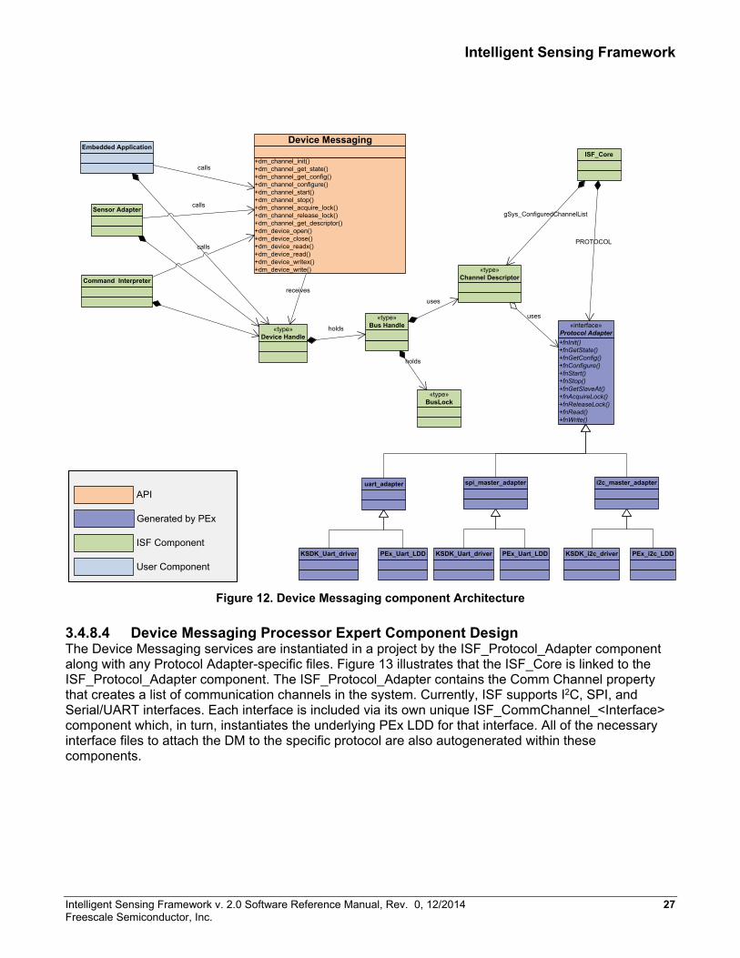
3.4.8.3 Device Messaging Module Design The Device Messaging (DM) service provides the DM API as a generic interface to any type of underlying protocol. Refer to Figure 12. The DM API function calls map directly to a set of function pointers that are autogenerated into the PROTOCOL and gSys_ConfiguredChannelList data structures. These function pointers are initialized to specific functions inside the corresponding Protocol Adapter for each interface. In addition to the functional interface, the Protocol Adapter creates a Bus Lock for each channel in the system. This Bus Lock is implemented as an MQX heavyweight semaphore in order to ensure that priority inversion problems can automatically be resolved by the RTOS.
26 Intelligent Sensing Framework v. 2.0 Software Reference Manual, Rev. 0, 12/2014 Freescale Semiconductor, Inc.
Intelligent Sensing Framework
Figure 12. Device Messaging component Architecture
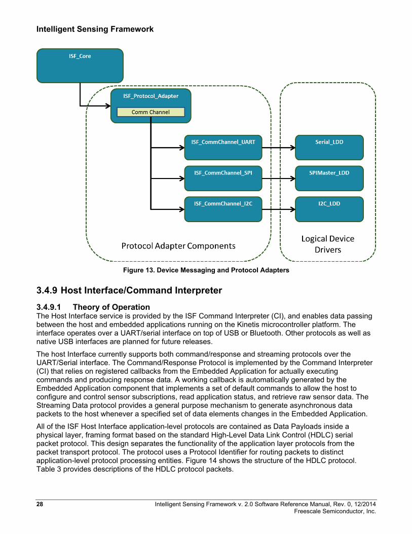
3.4.8.4 Device Messaging Processor Expert Component Design The Device Messaging services are instantiated in a project by the ISF_Protocol_Adapter component along with any Protocol Adapter-specific files. Figure 13 illustrates that the ISF_Core is linked to the ISF_Protocol_Adapter component. The ISF_Protocol_Adapter contains the Comm Channel property that creates a list of communication channels in the system. Currently, ISF supports I2C, SPI, and Serial/UART interfaces. Each interface is included via its own unique ISF_CommChannel_<Interface> component which, in turn, instantiates the underlying PEx LDD for that interface. All of the necessary interface files to attach the DM to the specific protocol are also autogenerated within these components.
+dm_channel_init()+dm_channel_get_state()+dm_channel_get_config()+dm_channel_configure()+dm_channel_start()+dm_channel_stop()+dm_channel_acquire_lock()+dm_channel_release_lock()+dm_channel_get_descriptor()+dm_device_open()+dm_device_close()+dm_device_readx()+dm_device_read()+dm_device_writex()+dm_device_write()
Device Messaging
+fnInit()+fnGetState()+fnGetConfig()+fnConfigure()+fnStart()+fnStop()+fnGetSlaveAt()+fnAcquireLock()+fnReleaseLock()+fnRead()+fnWrite()
«interface»Protocol Adapter
uart_adapter i2c_master_adapter
Embedded Application
Sensor Adapter
calls
calls
Command Interpreter
calls
spi_master_adapter
KSDK_Uart_driver PEx_Uart_LDD KSDK_i2c_driver PEx_i2c_LDDKSDK_Uart_driver PEx_Uart_LDD
Generated by PEx
API
ISF Component
User Component
«type»Channel Descriptor
uses«type»Bus Handle
«type»BusLock
holds
«type»Device Handle
holds
receives
uses
ISF_Core
gSys_ConfiguredChannelList
PROTOCOL
Intelligent Sensing Framework v. 2.0 Software Reference Manual, Rev. 0, 12/2014 27 Freescale Semiconductor, Inc.
Intelligent Sensing Framework
Figure 13. Device Messaging and Protocol Adapters
3.4.9 Host Interface/Command Interpreter 3.4.9.1 Theory of Operation The Host Interface service is provided by the ISF Command Interpreter (CI), and enables data passing between the host and embedded applications running on the Kinetis microcontroller platform. The interface operates over a UART/serial interface on top of USB or Bluetooth. Other protocols as well as native USB interfaces are planned for future releases.
The host Interface currently supports both command/response and streaming protocols over the UART/Serial interface. The Command/Response Protocol is implemented by the Command Interpreter (CI) that relies on registered callbacks from the Embedded Application for actually executing commands and producing response data. A working callback is automatically generated by the Embedded Application component that implements a set of default commands to allow the host to configure and control sensor subscriptions, read application status, and retrieve raw sensor data. The Streaming Data protocol provides a general purpose mechanism to generate asynchronous data packets to the host whenever a specified set of data elements changes in the Embedded Application.
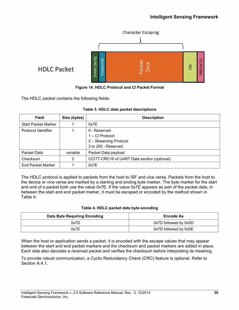
All of the ISF Host Interface application-level protocols are contained as Data Payloads inside a physical layer, framing format based on the standard High-Level Data Link Control (HDLC) serial packet protocol. This design separates the functionality of the application layer protocols from the packet transport protocol. The protocol uses a Protocol Identifier for routing packets to distinct application-level protocol processing entities. Figure 14 shows the structure of the HDLC protocol. Table 3 provides descriptions of the HDLC protocol packets.
28 Intelligent Sensing Framework v. 2.0 Software Reference Manual, Rev. 0, 12/2014 Freescale Semiconductor, Inc.
Intelligent Sensing Framework
Figure 14. HDLC Protocol and CI Packet Format
The HDLC packet contains the following fields:
Table 3. HDLC data packet descriptions
Field Size (bytes) Description Start Packet Marker 1 0x7E Protocol Identifier 1 0 - Reserved
1 – CI Protocol 2 – Streaming Protocol 3 to 255 - Reserved
Packet Data variable Packet Data payload Checksum 2 CCITT-CRC16 of UART Data section (optional) End Packet Marker 1 0x7E
The HDLC protocol is applied to packets from the host to ISF and vice versa. Packets from the host to the device or vice versa are marked by a starting and ending byte marker. The byte marker for the start and end of a packet both use the value 0x7E. If the value 0x7E appears as part of the packet data, in between the start and end packet marker, it must be escaped or encoded by the method shown in Table 4:
Table 4. HDLC packet data byte encoding
Data Byte Requiring Encoding Encode As 0x7D 0x7D followed by 0x5D 0x7E 0x7D followed by 0x5E
When the host or application sends a packet, it is encoded with the escape values that may appear between the start and end packet markers and the checksum and packet markers are added in place. Each side also decodes a received packet and verifies the checksum before interpreting its meaning.
To provide robust communication, a Cyclic Redundancy Check (CRC) feature is optional. Refer to Section A.4.1.
Intelligent Sensing Framework v. 2.0 Software Reference Manual, Rev. 0, 12/2014 29 Freescale Semiconductor, Inc.
Intelligent Sensing Framework
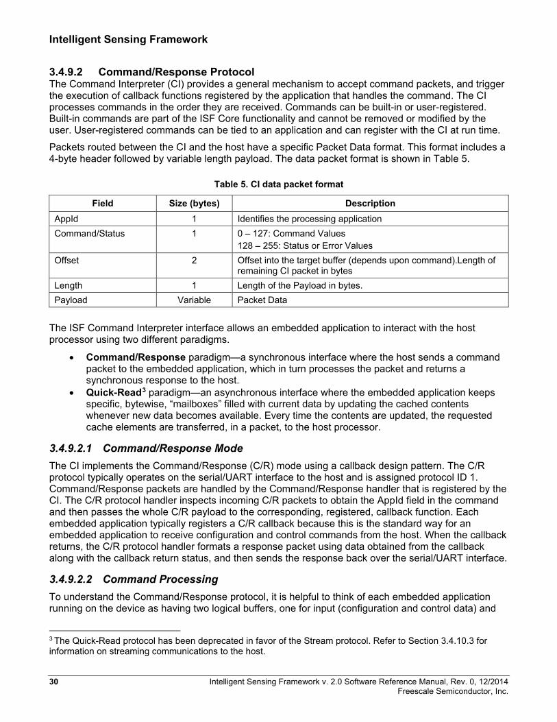
3.4.9.2 Command/Response Protocol The Command Interpreter (CI) provides a general mechanism to accept command packets, and trigger the execution of callback functions registered by the application that handles the command. The CI processes commands in the order they are received. Commands can be built-in or user-registered. Built-in commands are part of the ISF Core functionality and cannot be removed or modified by the user. User-registered commands can be tied to an application and can register with the CI at run time.
Packets routed between the CI and the host have a specific Packet Data format. This format includes a 4-byte header followed by variable length payload. The data packet format is shown in Table 5.
Table 5. CI data packet format
Field Size (bytes) Description AppId 1 Identifies the processing application Command/Status 1 0 – 127: Command Values
128 – 255: Status or Error Values Offset 2 Offset into the target buffer (depends upon command).Length of
remaining CI packet in bytes Length 1 Length of the Payload in bytes. Payload Variable Packet Data
The ISF Command Interpreter interface allows an embedded application to interact with the host processor using two different paradigms.
• Command/Response paradigm—a synchronous interface where the host sends a command packet to the embedded application, which in turn processes the packet and returns a synchronous response to the host.
• Quick-Read3 paradigm—an asynchronous interface where the embedded application keeps specific, bytewise, “mailboxes” filled with current data by updating the cached contents whenever new data becomes available. Every time the contents are updated, the requested cache elements are transferred, in a packet, to the host processor.
3.4.9.2.1 Command/Response Mode The CI implements the Command/Response (C/R) mode using a callback design pattern. The C/R protocol typically operates on the serial/UART interface to the host and is assigned protocol ID 1. Command/Response packets are handled by the Command/Response handler that is registered by the CI. The C/R protocol handler inspects incoming C/R packets to obtain the AppId field in the command and then passes the whole C/R payload to the corresponding, registered, callback function. Each embedded application typically registers a C/R callback because this is the standard way for an embedded application to receive configuration and control commands from the host. When the callback returns, the C/R protocol handler formats a response packet using data obtained from the callback along with the callback return status, and then sends the response back over the serial/UART interface.
3.4.9.2.2 Command Processing To understand the Command/Response protocol, it is helpful to think of each embedded application running on the device as having two logical buffers, one for input (configuration and control data) and
3 The Quick-Read protocol has been deprecated in favor of the Stream protocol. Refer to Section 3.4.10.3 for information on streaming communications to the host.
30 Intelligent Sensing Framework v. 2.0 Software Reference Manual, Rev. 0, 12/2014 Freescale Semiconductor, Inc.

Intelligent Sensing Framework
one for the application’s output data. Structurally, the buffers can be thought of as having a fixed layout such that a value at a specific location within the buffer always contains the same type of data.
In typical usage, the input buffer is often overlaid with a C structure to facilitate use of the input data.
Each application can allocate its own configuration and output buffers. The host can send data to a particular target application by writing data into specific locations within that application’s configuration buffer. The locations are specified as an offset into the buffer along with the number of bytes to write, followed by the actual data values. The protocol also supports commands for reading the configuration buffer and the output data buffer.
3.4.9.2.3 Built-in Commands Device Info command The Device Info command (DevInfo) is a special Command/Response mode command. It does not conform to the complete Command/Response protocol described previously. The DevInfo command is invoked at runtime by sending the following string via the Host interface:
7E 01 00 00 00 00 7E
The CI handles the command itself and returns a response packet formatted as shown below and interpreted in Table 6.
7E 01 00 80 00 00 00 00 00 00 00 02 00 00 82 37 00 00 00 00 00 00 7E
Table 6. Packet offset and fields of the DevInfo command
Packet Offset
Field Name Source Description
0 Start Character ISF 0x7E Packet Start 1 Protocol ID ISF 0x01 for Command/Response protocol 2 Command ISF Echoes the Application ID providing the Response (for example, 0) 3 Command Status ISF A status value of 0x80 indicates successful completion. Any other
value in the lower seven bits represents status/error information codes specific to the issued command.
4-7 device_id ROM 32 bit pseudo-random, part identification value 8-9 rom_version ROM 16 bit ROM version code: major.minor (for example, 01 00 = 1.0)
10-11 fw_version ISF 16 bit firmware version code: major.minor (for example, 01 2C = 1.44)
12-13 hw_version ROM 16 bit hardware version code: major.minor
Intelligent Sensing Framework v. 2.0 Software Reference Manual, Rev. 0, 12/2014 31 Freescale Semiconductor, Inc.
Intelligent Sensing Framework
Packet Offset
Field Name Source Description
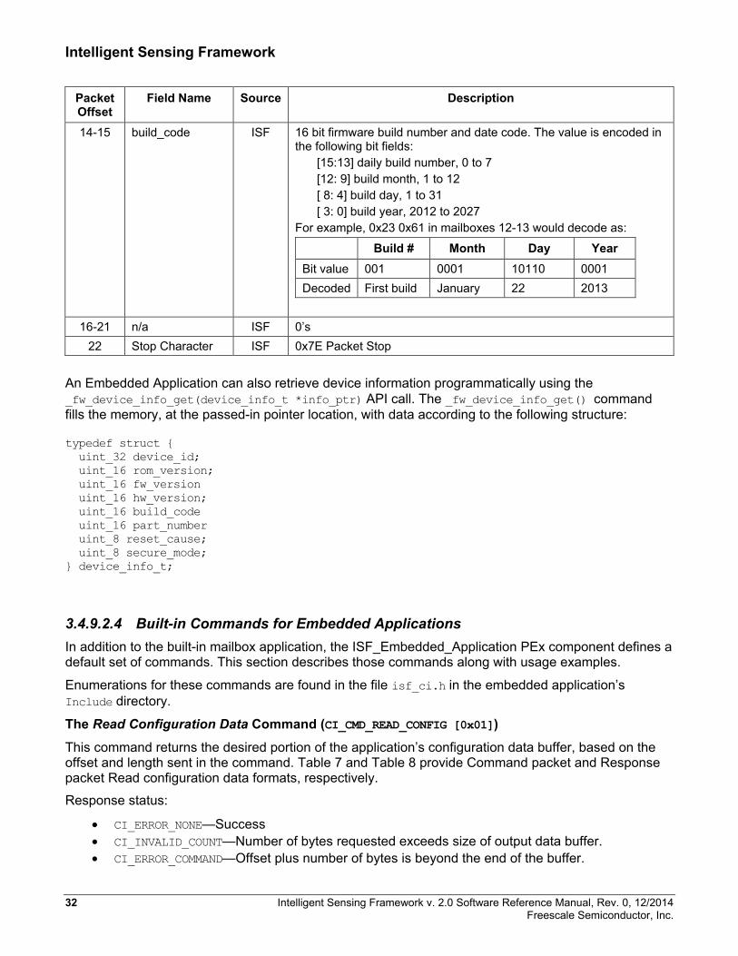
14-15 build_code ISF 16 bit firmware build number and date code. The value is encoded in the following bit fields:
[15:13] daily build number, 0 to 7 [12: 9] build month, 1 to 12 [ 8: 4] build day, 1 to 31 [ 3: 0] build year, 2012 to 2027
For example, 0x23 0x61 in mailboxes 12-13 would decode as:
Build # Month Day Year Bit value 001 0001 10110 0001 Decoded First build January 22 2013
16-21 n/a ISF 0’s
22 Stop Character ISF 0x7E Packet Stop
An Embedded Application can also retrieve device information programmatically using the _fw_device_info_get(device_info_t *info_ptr) API call. The _fw_device_info_get() command fills the memory, at the passed-in pointer location, with data according to the following structure:
typedef struct { uint_32 device_id; uint_16 rom_version; uint_16 fw_version uint_16 hw_version; uint_16 build_code uint_16 part_number uint_8 reset_cause; uint_8 secure_mode; } device_info_t;
3.4.9.2.4 Built-in Commands for Embedded Applications In addition to the built-in mailbox application, the ISF_Embedded_Application PEx component defines a default set of commands. This section describes those commands along with usage examples.
Enumerations for these commands are found in the file isf_ci.h in the embedded application’s Include directory.
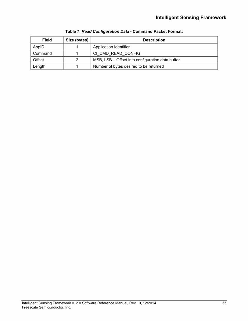
The Read Configuration Data Command (CI_CMD_READ_CONFIG [0x01])
This command returns the desired portion of the application’s configuration data buffer, based on the offset and length sent in the command. Table 7 and Table 8 provide Command packet and Response packet Read configuration data formats, respectively.
Response status:
• CI_ERROR_NONE—Success • CI_INVALID_COUNT—Number of bytes requested exceeds size of output data buffer. • CI_ERROR_COMMAND—Offset plus number of bytes is beyond the end of the buffer.
32 Intelligent Sensing Framework v. 2.0 Software Reference Manual, Rev. 0, 12/2014 Freescale Semiconductor, Inc.
Intelligent Sensing Framework
Table 7. Read Configuration Data - Command Packet Format:
Field Size (bytes) Description AppID 1 Application Identifier Command 1 CI_CMD_READ_CONFIG Offset 2 MSB, LSB – Offset into configuration data buffer Length 1 Number of bytes desired to be returned
Intelligent Sensing Framework v. 2.0 Software Reference Manual, Rev. 0, 12/2014 33 Freescale Semiconductor, Inc.
Intelligent Sensing Framework
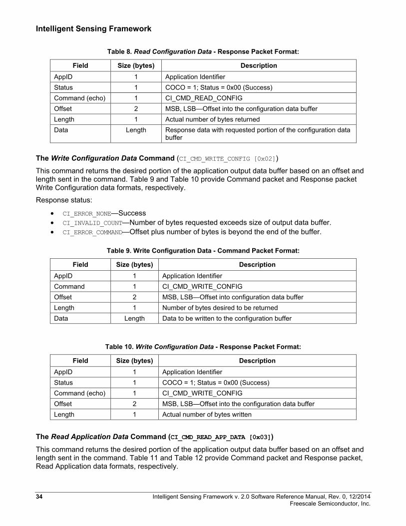
Table 8. Read Configuration Data - Response Packet Format:
Field Size (bytes) Description AppID 1 Application Identifier Status 1 COCO = 1; Status = 0x00 (Success) Command (echo) 1 CI_CMD_READ_CONFIG Offset 2 MSB, LSB—Offset into the configuration data buffer Length 1 Actual number of bytes returned Data Length Response data with requested portion of the configuration data
buffer
The Write Configuration Data Command (CI_CMD_WRITE_CONFIG [0x02]) This command returns the desired portion of the application output data buffer based on an offset and length sent in the command. Table 9 and Table 10 provide Command packet and Response packet Write Configuration data formats, respectively.
Response status:
• CI_ERROR_NONE—Success • CI_INVALID_COUNT—Number of bytes requested exceeds size of output data buffer. • CI_ERROR_COMMAND—Offset plus number of bytes is beyond the end of the buffer.
Table 9. Write Configuration Data - Command Packet Format:
Field Size (bytes) Description AppID 1 Application Identifier Command 1 CI_CMD_WRITE_CONFIG Offset 2 MSB, LSB—Offset into configuration data buffer Length 1 Number of bytes desired to be returned Data Length Data to be written to the configuration buffer
Table 10. Write Configuration Data - Response Packet Format:
Field Size (bytes) Description AppID 1 Application Identifier Status 1 COCO = 1; Status = 0x00 (Success) Command (echo) 1 CI_CMD_WRITE_CONFIG Offset 2 MSB, LSB—Offset into the configuration data buffer Length 1 Actual number of bytes written
The Read Application Data Command (CI_CMD_READ_APP_DATA [0x03])
This command returns the desired portion of the application output data buffer based on an offset and length sent in the command. Table 11 and Table 12 provide Command packet and Response packet, Read Application data formats, respectively.
34 Intelligent Sensing Framework v. 2.0 Software Reference Manual, Rev. 0, 12/2014 Freescale Semiconductor, Inc.

Intelligent Sensing Framework
Response status:
• CI_ERROR_NONE—Success • CI_INVALID_COUNT—Number of bytes requested exceeds size of output data buffer. • CI_ERROR_COMMAND—Offset plus number of bytes is beyond the end of the buffer.
Table 11. Read Application Data - Command Packet Format:
Field Size (bytes) Description AppID 1 Application Identifier Command 1 CI_CMD_READ_APP_DATA Offset 2 MSB, LSB—Offset into output data buffer Length 1 Number of bytes desired to be returned
Table 12. Read Application Data - Response Packet Format:
Field Size (bytes) Description AppID 1 Application Identifier Status 1 COCO = 1; Status = 0x00 (Success) Command (echo) 1 CI_CMD_READ_APP_DATA Offset 2 MSB, LSB—Offset into output data buffer Length 1 Actual number of bytes returned Data Length Response data with requested portion of the output data buffer
The Update Quick-Read Command (CI_CMD_UPDATE_QUICKREAD [0x04])
This command causes the application to update the Quick-Read internal buffers from the output data buffer. It causes the CI to generate a Quick-Read packet to the host if it is configured and enabled. The command returns a confirmation. Table 13 and Table 14 provide Command packet and Response packet, Update Quick- Read data formats, respectively.
Response status:
• CI_ERROR_NONE—Success
Table 13. Update Quick-Read - Command Packet Format:
Field Size (bytes) Description AppID 1 Application Identifier Command 1 CI_CMD_UPDATE_QUICKREAD Offset 2 N/A Length 1 N/A
Intelligent Sensing Framework v. 2.0 Software Reference Manual, Rev. 0, 12/2014 35 Freescale Semiconductor, Inc.

Intelligent Sensing Framework
Table 14. Update Quick-Read - Response Packet Example:
Field Size (bytes) Description AppID 1 Application Identifier Status 1 COCO = 1; Status = 0x00 (Success) Command (echo) 1 CI_CMD_UPDATE_QUICKREAD Offset 2 N/A Length 1 N/A
The Application Reset Command (CI_CMD_RESET_APP [0x06])
This command causes the application to reset its internal state to as close as possible to its initial state out of Power-On Reset. The command returns a confirmation. Table 15 and Table 16 provide Command packet and Response packet, Application Reset data formats, respectively.
Response status:
• CI_ERROR_NONE—Success
Table 15. Application Reset - Command Packet Format:
Field Size (bytes) Description AppID 1 Application Identifier Command 1 CI_CMD_RESET_APP Offset 2 N/A Length 1 N/A
Table 16. Application Reset - Response Packet Example:
Field Size (bytes) Description AppID 1 Application Identifier Status 1 COCO = 1; Status = 0x00 (Success) Command (echo) 1 CI_CMD_RESET_APP Offset 2 N/A Length 1 N/A
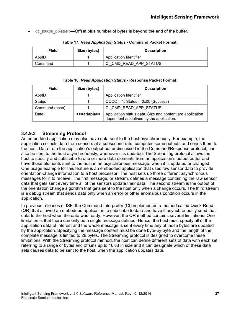
The Read Application Status Command (CI_CMD_READ_APP_STATUS [0x05])
This command returns an application’s status information. The command must be explicitly implemented in the embedded application’s callback function and the format and contents of the information returned is implementation-specific. Table 17 and Table 18 provide Command packet and Response packet, Read Application Status data formats, respectively.
Response status:
• CI_ERROR_NONE—Success
• CI_INVALID_COUNT—Number of bytes requested exceeds size of output data buffer.
36 Intelligent Sensing Framework v. 2.0 Software Reference Manual, Rev. 0, 12/2014 Freescale Semiconductor, Inc.
Intelligent Sensing Framework
• CI_ERROR_COMMAND—Offset plus number of bytes is beyond the end of the buffer.
Table 17. Read Application Status - Command Packet Format:
Field Size (bytes) Description AppID 1 Application Identifier Command 1 CI_CMD_READ_APP_STATUS
Table 18. Read Application Status - Response Packet Format:
Field Size (bytes) Description AppID 1 Application Identifier Status 1 COCO = 1; Status = 0x00 (Success) Command (echo) 1 CI_CMD_READ_APP_STATUS Data <<Variable>> Application status data. Size and content are application
dependent as defined by the application.
3.4.9.3 Streaming Protocol An embedded application may also have data sent to the host asynchronously. For example, the application collects data from sensors at a subscribed rate, computes some outputs and sends them to the host. Data from the application’s output buffer discussed in the Command/Response protocol, can also be sent to the host asynchronously, whenever it is updated. The Streaming protocol allows the host to specify and subscribe to one or more data elements from an application’s output buffer and have those elements sent to the host in an asynchronous message, when it is updated or changed. One usage example for this feature is an embedded application that uses raw sensor data to provide orientation-change information to a host processor. The host sets up three different asynchronous messages for it to receive. The first message, or stream, defines a message containing the raw sensor data that gets sent every time all of the sensors update their data. The second stream is the output of the orientation change algorithm that gets sent to the host only when a change occurs. The third stream is a debug stream that sends data only when an error or other anomalous condition occurs in the application.
In previous releases of ISF, the Command Interpreter (CI) implemented a method called Quick-Read (QR) that allowed an embedded application to subscribe to data and have it asynchronously send that data to the host when the data was ready. However, the QR method contains several limitations. One limitation is that there can only be a single message defined. Hence, the host must specify all of the application data of interest and the whole message is sent every time any of those bytes are updated by the application. Specifying the message content must be done byte-by-byte and the length of the complete message is limited to 28 bytes. The Streaming protocol is designed to overcome these limitations. With the Streaming protocol method, the host can define different sets of data with each set referring to a range of bytes and offsets up to 16KB in size and it can designate which of these data sets causes data to be sent to the host, when the application updates data.
Intelligent Sensing Framework v. 2.0 Software Reference Manual, Rev. 0, 12/2014 37 Freescale Semiconductor, Inc.

Intelligent Sensing Framework
The Streaming protocol defines a concept called streams, which defines a logical data flow of messages, containing a specified set of data that the host can receive in one data packet. Different streams are identified by a unique Stream ID value. A stream is specified using a Stream Configuration object. This object contain two lists:
• The Stream Element object list • The Trigger Mask list
Each stream element object describes a slice of an application’s output buffer and includes an element ID, the starting offset within the application’s output buffer, and the number of bytes to transfer. The Trigger Mask list is a list of bytes that contain information about which stream elements have been updated by the application. This information is used to specify and track when stream data gets sent to the host. The stream data sent to the host is referred to in the following discussion as the update packet.
3.4.9.4 Module Design Figure 15 shows the high-level layering and interfaces of the new CI design. The CI uses Device Messaging to interact with the serial/UART interface for character reception and transmission to the host. Use of this abstraction allows the CI to operate over different transports. This is important when additional transports become available such as UDP, TCP, and ZigBee. The CI task state machine receives characters and validates the HDLC framing. Once a complete, valid HDLC frame has been received, it uses the protocol ID in the packet to route the packet to the registered protocol handler. In ISF R2.0 there are two implemented protocols: Command/Response and Streaming. For the Command/Response protocol, the handler interprets the AppID, calls the appropriate application callback function, and returns the formatted response. For the Streaming protocol, the handler interprets the command, formats the response according to the internal protocol state, and returns the response.
38 Intelligent Sensing Framework v. 2.0 Software Reference Manual, Rev. 0, 12/2014 Freescale Semiconductor, Inc.
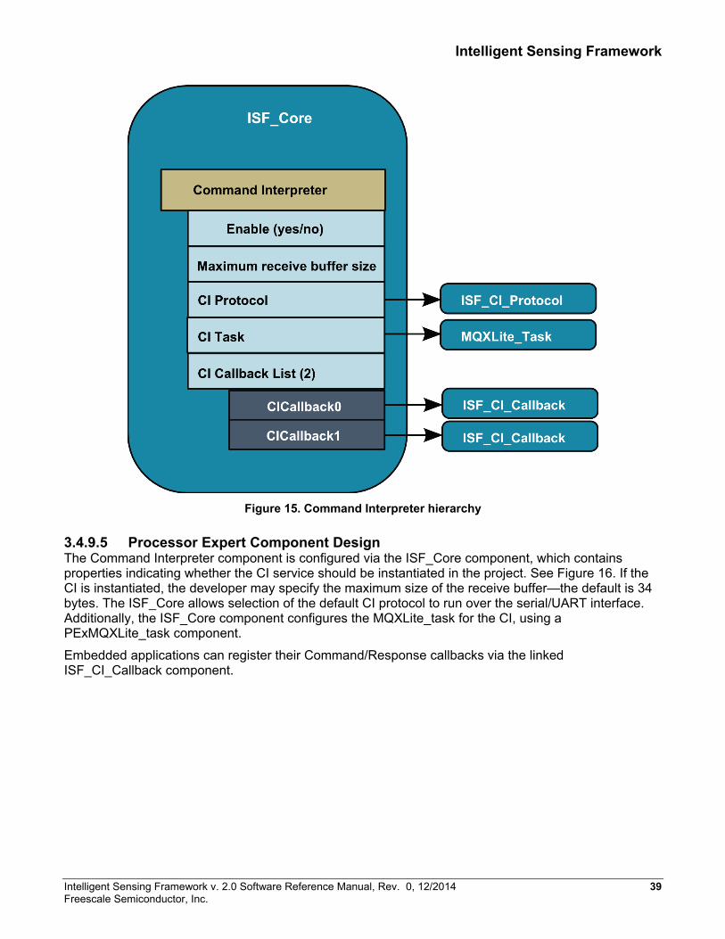
Intelligent Sensing Framework
Figure 15. Command Interpreter hierarchy
3.4.9.5 Processor Expert Component Design The Command Interpreter component is configured via the ISF_Core component, which contains properties indicating whether the CI service should be instantiated in the project. See Figure 16. If the CI is instantiated, the developer may specify the maximum size of the receive buffer—the default is 34 bytes. The ISF_Core allows selection of the default CI protocol to run over the serial/UART interface. Additionally, the ISF_Core component configures the MQXLite_task for the CI, using a PExMQXLite_task component.
Embedded applications can register their Command/Response callbacks via the linked ISF_CI_Callback component.
Intelligent Sensing Framework v. 2.0 Software Reference Manual, Rev. 0, 12/2014 39 Freescale Semiconductor, Inc.

Intelligent Sensing Framework
. Command Interpreter Receive Packet Activity Diagram
3.4.10 Power Manager 3.4.10.1 Theory of Operation The Power Manager (PM) provides APIs that allow an embedded application to request changes to the operating power mode of the device. See Figure 17. In general, power savings is expected to be achieved by controlling the microcontroller idle behavior by managing the enable status of the clock(s) driving the device along with its peripherals.
The Power Management services are responsible for maintaining operational consistency for ISF components as the device power states are changed. Each implementation of ISF on a new hardware device must map the ISF-defined power modes to the device’s available power modes such that the total power consumed in each mode is less than or equal to each higher-powered mode subject to CPU loading constraints.
40 Intelligent Sensing Framework v. 2.0 Software Reference Manual, Rev. 0, 12/2014 Freescale Semiconductor, Inc.
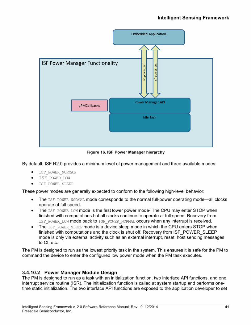
Intelligent Sensing Framework
Figure 16. ISF Power Manager hierarchy
By default, ISF R2.0 provides a minimum level of power management and three available modes:
• ISF_POWER_NORMAL • ISF_POWER_LOW • ISF_POWER_SLEEP
These power modes are generally expected to conform to the following high-level behavior:
• The ISF_POWER_NORMAL mode corresponds to the normal full-power operating mode—all clocks operate at full speed.
• The ISF_POWER_LOW mode is the first lower power mode- The CPU may enter STOP when finished with computations but all clocks continue to operate at full speed. Recovery from ISF_POWER_LOW mode back to ISF_POWER_NORMAL occurs when any interrupt is received.
• The ISF_POWER_SLEEP mode is a device sleep mode in which the CPU enters STOP when finished with computations and the clock is shut off. Recovery from ISF_POWER_SLEEP mode is only via external activity such as an external interrupt, reset, host sending messages to CI, etc.
The PM is designed to run as the lowest priority task in the system. This ensures it is safe for the PM to command the device to enter the configured low power mode when the PM task executes.
3.4.10.2 Power Manager Module Design The PM is designed to run as a task with an initialization function, two interface API functions, and one interrupt service routine (ISR). The initialization function is called at system startup and performs one-time static initialization. The two interface API functions are exposed to the application developer to set
Intelligent Sensing Framework v. 2.0 Software Reference Manual, Rev. 0, 12/2014 41 Freescale Semiconductor, Inc.

Intelligent Sensing Framework
the desired power level and to get the current power level setting. The ISR is used internally to keep track of time when the device is in low power. The PM task implements the low power functionality and is created along with other Freescale MQXLite™ RTOS tasks during startup.
At startup, the PM performs a one-time initialization including initialization of the power mode to the ISF_POWER_NORMAL setting. After initialization has been completed, the PM idle task is created by Freescale MQXLite RTOS along with all the other tasks in the system. The idle task runs at the lowest priority level in the system. This means it will be executed by the OS only when all other higher priority tasks are inactive, for example, by being blocked on Freescale MQXLite ™ RTOS objects waiting for an event occur. When the idle task does run, it sets the device to the currently active power level. Thus, for all power level settings, except for ISF_POWER_SLEEP, power management is automatically implemented whenever all higher priority tasks are inactive. If the power level is set to ISF_POWER_NORMAL, the isf_power_set() function sets the level and exits. When the idle task does run, it performs a task block operation on itself to prevent it from running to completion. When an application subsequently sets the power level to something other than ISF_POWER_NORMAL, the idle task is unblocked, allowing it to complete and initiate the low power modes. If the power level is set to ISF_POWER_LOW, when the idle task does run, it executes a WFI instruction. In this mode, any interrupt wakes the CPU. At a minimum, the peripheral timers are running and wake up the CPU when an interrupt occurs. The application may also have programmed other peripherals on the device to generate interrupts as well, causing a wake up. After interrupt ISRs are serviced and when all higher priority tasks are inactive, the idle task runs and returns the device to WFI mode assuming that the power level remains set at ISF_POWER_LOW. If the power level is set to ISF_POWER_SLEEP when the idle task runs, it immediately puts the device into Deep Sleep mode. In this mode, all clocks in the device are stopped. An external interrupt is required to wake the device.
ISF R2.0 Power Management modes are implemented as follows
• ISF_POWER_NORMAL—Microcontroller is always running. Idle Task executes NOP instruction. • ISF_POWER_LOW—Microcontroller is set into NORMAL SLEEP mode. Idle Task executes WFI
after each wakeup. Idle is typically reached after an interrupt has awoken the microcontroller and all other possible scheduled activities resulting from the interrupt were completed.
• ISF_POWER_SLEEP—Microcontroller is set into DEEP SLEEP mode. Phase Lock Loop (PLL) remains enabled. Idle Task does not execute while in SLEEP.
The Power Manager configuration is exposed in Processor Expert as part of the ISF_Core component. A checkbox is used to specify whether the component is enabled for a project.
3.5 Application Support Component Details 3.5.1 Embedded Application Component 3.5.1.1 Theory of Operation The Embedded Application component allows a developer to configure and generate a complete and working example of an embedded application that subscribes to sensor data and makes it available to the Host Interface without writing a single line of code. Hooks are generated within the code for placement of custom functionality.
A typical workflow for developing a custom embedded application starts with the Embedded Application component’s default-generated code that can be extended or modified as necessary to achieve the desired custom functionality.
In some cases, the application model constructed in the Embedded Application may be too constraining to be useful in the application developer’s design. Developers are not required to use the provided
42 Intelligent Sensing Framework v. 2.0 Software Reference Manual, Rev. 0, 12/2014 Freescale Semiconductor, Inc.

Intelligent Sensing Framework
Embedded Application component. It is intended to be used as a starting point to understand the available ISF API calls; later it can be replaced with a custom application, linked directly with the ISF embedded middleware.
3.5.1.2 Embedded Application Module Design The ISF_Embedded_Application PEx component accepts a set of configuration properties and generates the software for the Embedded Application task. See Figure 18. The resulting Embedded Application contains three major sections:
• Host Interface Callback function • The Main Application • An Application Sensor State Machine.
Each section is tailored to the developer’s application by the properties assigned in the PEx component.
Intelligent Sensing Framework v. 2.0 Software Reference Manual, Rev. 0, 12/2014 43 Freescale Semiconductor, Inc.
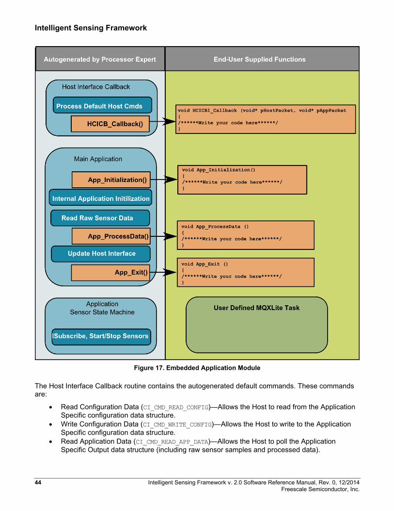
Intelligent Sensing Framework
Figure 17. Embedded Application Module
The Host Interface Callback routine contains the autogenerated default commands. These commands are:
• Read Configuration Data (CI_CMD_READ_CONFIG)—Allows the Host to read from the Application Specific configuration data structure.
• Write Configuration Data (CI_CMD_WRITE_CONFIG)—Allows the Host to write to the Application Specific configuration data structure.
• Read Application Data (CI_CMD_READ_APP_DATA)—Allows the Host to poll the Application Specific Output data structure (including raw sensor samples and processed data).
44 Intelligent Sensing Framework v. 2.0 Software Reference Manual, Rev. 0, 12/2014 Freescale Semiconductor, Inc.
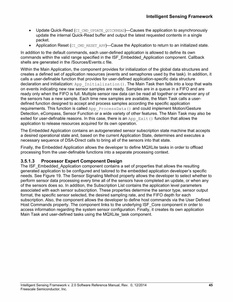
Intelligent Sensing Framework
• Update Quick-Read (CI_CMD_UPDATE_QUICKREAD)—Causes the application to asynchronously update the internal Quick-Read buffer and output the latest requested contents in a single packet.
• Application Reset (CI_CMD_RESET_APP)—Cause the Application to return to an initialized state.
In addition to the default commands, each user-defined application is allowed to define its own commands within the valid range specified in the ISF_Embedded_Application component. Callback shells are generated in the /Sources/Events.c file.
Within the Main Application, the component provides for initialization of the global data structures and creates a defined set of application resources (events and semaphores used by the task). In addition, it calls a user-definable function that provides for user-defined application-specific data structure declaration and initialization: App_Initialization(). The Main Task then falls into a loop that waits on events indicating new raw sensor samples are ready. Samples are in a queue in a FIFO and are ready only when the FIFO is full. Multiple sensor raw data can be read all together or whenever any of the sensors has a new sample. Each time new samples are available, the Main Task calls a user-defined function designed to accept and process samples according the specific application requirements. This function is called App_ProcessData() and could implement Motion/Gesture Detection, eCompass, Sensor Function or a wide variety of other features. The Main Task may also be exited for user-definable reasons. In this case, there is an App_Exit() function that allows the application to release resources acquired for its own operation.
The Embedded Application contains an autogenerated sensor subscription state machine that accepts a desired operational state and, based on the current Application State, determines and executes a necessary sequence of DSA-Direct calls to bring all of the sensors into that state.
Finally, the Embedded Application allows the developer to define MQXLite tasks in order to offload processing from the user-definable functions into a separate processing context.
3.5.1.3 Processor Expert Component Design The ISF_Embedded_Application component contains a set of properties that allows the resulting generated application to be configured and tailored to the embedded application developer’s specific needs. See Figure 19. The Sensor Signaling Method property allows the developer to select whether to perform sensor data processing every time all of the sensors have completed an update, or when any of the sensors does so. In addition, the Subscription List contains the application level parameters associated with each sensor subscription. These properties determine the sensor type, sensor output format, the specific sensor selected, the desired sampling rate, and the FIFO depth for each subscription. Also, the component allows the developer to define host commands via the User Defined Host Commands property. The component links to the underlying ISF_Core component in order to access information regarding the system sensor configuration. Finally, it creates its own application Main Task and user-defined tasks using the MQXLite_task component.
Intelligent Sensing Framework v. 2.0 Software Reference Manual, Rev. 0, 12/2014 45 Freescale Semiconductor, Inc.
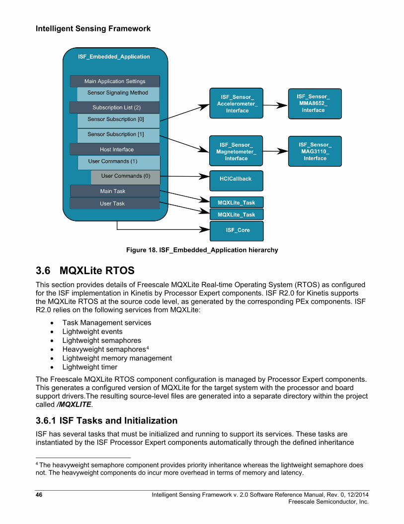
Intelligent Sensing Framework
Figure 18. ISF_Embedded_Application hierarchy
3.6 MQXLite RTOS This section provides details of Freescale MQXLite Real-time Operating System (RTOS) as configured for the ISF implementation in Kinetis by Processor Expert components. ISF R2.0 for Kinetis supports the MQXLite RTOS at the source code level, as generated by the corresponding PEx components. ISF R2.0 relies on the following services from MQXLite:
• Task Management services • Lightweight events • Lightweight semaphores • Heavyweight semaphores4 • Lightweight memory management • Lightweight timer
The Freescale MQXLite RTOS component configuration is managed by Processor Expert components. This generates a configured version of MQXLite for the target system with the processor and board support drivers.The resulting source-level files are generated into a separate directory within the project called /MQXLITE.
3.6.1 ISF Tasks and Initialization ISF has several tasks that must be initialized and running to support its services. These tasks are instantiated by the ISF Processor Expert components automatically through the defined inheritance
4 The heavyweight semaphore component provides priority inheritance whereas the lightweight semaphore does not. The heavyweight components do incur more overhead in terms of memory and latency.
46 Intelligent Sensing Framework v. 2.0 Software Reference Manual, Rev. 0, 12/2014 Freescale Semiconductor, Inc.

Intelligent Sensing Framework
hierarchy. Processor Expert allows the entry function name, priority, and stack size of the tasks to be modified, but this is not recommended by Freescale. The tasks created include, but are not limited to, the Command Interpreter task, the Power Manager task, the Bus Manager task, and the Initialization task. The Initialization task generates an MQX lightweight event called SYSTEM_READY_EVENT at the completion of the ISF initialization process. In order to guarantee proper initialization, user-defined tasks must wait for this event to be completed prior to execution of their own initializations. The following code has been inserted at the beginning of the task to wait for the event:
// Wait for ISF system initialization to complete. isf_system_sync();
Care should be taken to honor the task priority assignments made by ISF for proper system operations. User tasks must not be assigned at higher priority levels than ISF system tasks. As configured, out-of-the-box ISF tasks are at priorities between 9 and 12. Therefore, user tasks are expected to run at priority numbers of 13 or greater. ISF task IDs start at 50 and increment. User-defined tasks are expected to be defined with task IDs less than 50.
Intelligent Sensing Framework v. 2.0 Software Reference Manual, Rev. 0, 12/2014 47 Freescale Semiconductor, Inc.

Revision History
4. Revision History Table 19. Revision history
Rev. No. Date Description 0 12/2014 Initial public release
48 Intelligent Sensing Framework v. 2.0 Software Reference Manual, Rev. 0, 12/2014 Freescale Semiconductor, Inc.

Streaming Protocol for Host Communication
Appendix A. Streaming Protocol for Host Communication A.1 Introduction An Embedded Application (EA) may have data to send to the host, asynchronously. For example, the EA collects data from sensors at a subscribed rate. When the sensor produces the data, the EA reads it and sends it to the host. The EA can offer different types of data to the host in a buffer and the host can select which of these data types it needs. A means is needed to allow the host to subscribe to this data and choose which data it wants.
The Command Interpreter (CI) implemented a method called Quick-Read (QR) that allows an embedded application to subscribe to data and have it asynchronously send data to the host, when the data is ready. QR was implemented as part of the Mailbox protocol that is a part of the CI. However, the QR method contains several limitations. One limitation is that the host has to select the data it needs on a byte basis, and if any of those bytes are updated by the EA, all of the selected bytes are sent to the host. In addition, the length of the data is limited to 28 bytes. The Stream Protocol (SP) is designed to overcome these limitations. With the SP method, the host can define different sets of data with each set referring to a range of bytes and offsets up to 16 KB in size. It can designate which of these datasets causes data to be sent to the host when the EA updates the data.
A.2 General Description
The SP defines a concept called streams that encapsulates a set of data that the host can receive in a single data packet. Streams are identified by a unique ID value and contain details of the data pertaining to the stream. A stream is implemented with the Stream Configuration object. This object contain two lists:
• The Stream Element object list • The Trigger Mask list.
The Stream Element object describes a dataset that includes an ID, the length, and the offset. The Trigger Mask list is a list of bytes that contains information indicating which dataset is updated by the EA. This information is used to determine when a stream is sent to the host. The stream data sent to the host is referred to as the Update packet.
Intelligent Sensing Framework v. 2.0 Software Reference Manual, Rev. 0, 12/2014 49 Freescale Semiconductor, Inc.

Streaming Protocol for Host Communication
A.3 Stream Configuration The Stream Configuration object allows the host to store a Stream Element and Trigger Mask list. The Stream Element list consists of one or more Datasets with each Dataset containing an ID, length, and offset. The Trigger Mask list is an array of byte(s) with each bit corresponding to a Dataset. The data structure of a Stream Configuration is implemented as follows:
Field Size (bytes) Description streamID 1 ID of this stream numElements 1 Number of elements in the pElementList *pTriggerMask 4 Pointer to an array of trigger byte(s) *pElementList 4 Pointer to a list of Stream Element(s)
The stream ID is unique in the system and only one stream can exist with a particular ID value. When an Update packet is sent to the host, the stream ID is included to identify the stream.
The Stream Element list can specify multiple Datasets and the same Dataset ID can be specified more than once.
When a stream is created, a set of Trigger Mask byte(s) is required along with Stream Element list information. The number of trigger bytes depends on the number of elements in the stream. Since a byte contains 8 bits, each byte can represent up to 8 elements.
Each bit in the trigger byte corresponds to a dataset. For example, bit 0 of the first byte in the pTriggerMask corresponds to the first Dataset in the pElementList. In other words, pTriggerMask[0] bit0 corresponds to pElementList[0].
When the EA updates data that overlaps with a Dataset, the trigger bit corresponding to the Dataset is cleared. If the Trigger Mask bit is set, it means that the Update packet cannot be sent until the bit is cleared. All bits in the Trigger Mask list must be cleared before the Update Packet is sent to the host.
A.3.1 Stream Elements The Stream Element object contains a description of a Dataset. The Dataset contains information to describe a set of data that is shown below. The Dataset ID is the identifier for the dataset.
Field Size (bytes) Description datasetID 1 ID of this dataset Offset 2 Offset into the EA data buffer Length 2 Length of the desired data
The Dataset ID is defined by the EA. The Dataset specifies a segment of data or all of the data from the data buffer that the EA has to offer to the host.
A.3.2 Stream APIs A summary of the SP APIs are listed here. The detailed description can be found in the isf_ci_stream.h file.
50 Intelligent Sensing Framework v. 2.0 Software Reference Manual, Rev. 0, 12/2014 Freescale Semiconductor, Inc.
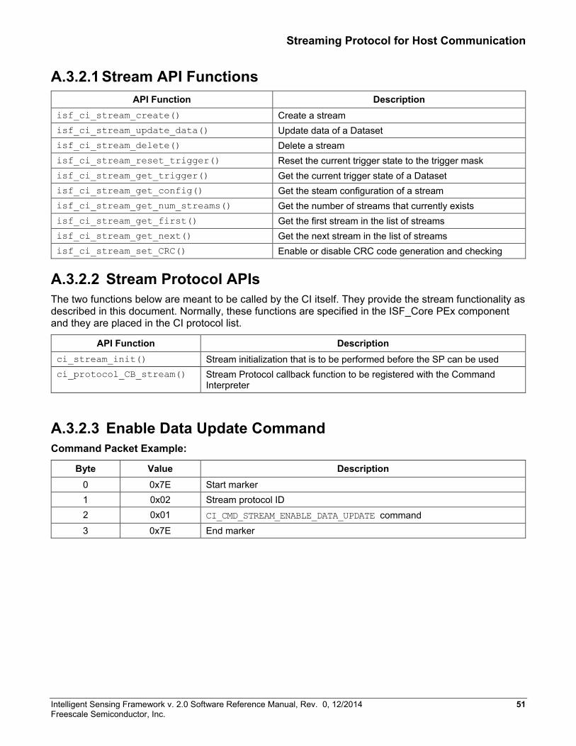
Streaming Protocol for Host Communication
A.3.2.1 Stream API Functions API Function Description
isf_ci_stream_create() Create a stream isf_ci_stream_update_data() Update data of a Dataset isf_ci_stream_delete() Delete a stream isf_ci_stream_reset_trigger() Reset the current trigger state to the trigger mask isf_ci_stream_get_trigger() Get the current trigger state of a Dataset isf_ci_stream_get_config() Get the steam configuration of a stream isf_ci_stream_get_num_streams() Get the number of streams that currently exists isf_ci_stream_get_first() Get the first stream in the list of streams isf_ci_stream_get_next() Get the next stream in the list of streams isf_ci_stream_set_CRC() Enable or disable CRC code generation and checking
A.3.2.2 Stream Protocol APIs The two functions below are meant to be called by the CI itself. They provide the stream functionality as described in this document. Normally, these functions are specified in the ISF_Core PEx component and they are placed in the CI protocol list.
API Function Description ci_stream_init() Stream initialization that is to be performed before the SP can be used ci_protocol_CB_stream() Stream Protocol callback function to be registered with the Command
Interpreter
A.3.2.3 Enable Data Update Command Command Packet Example:
Byte Value Description 0 0x7E Start marker 1 0x02 Stream protocol ID 2 0x01 CI_CMD_STREAM_ENABLE_DATA_UPDATE command 3 0x7E End marker
Intelligent Sensing Framework v. 2.0 Software Reference Manual, Rev. 0, 12/2014 51 Freescale Semiconductor, Inc.
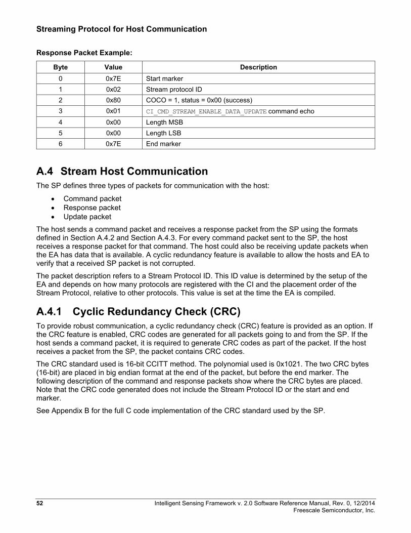
Streaming Protocol for Host Communication
Response Packet Example:
Byte Value Description 0 0x7E Start marker 1 0x02 Stream protocol ID 2 0x80 COCO = 1, status = 0x00 (success) 3 0x01 CI_CMD_STREAM_ENABLE_DATA_UPDATE command echo 4 0x00 Length MSB 5 0x00 Length LSB 6 0x7E End marker
A.4 Stream Host Communication The SP defines three types of packets for communication with the host:
• Command packet • Response packet • Update packet
The host sends a command packet and receives a response packet from the SP using the formats defined in Section A.4.2 and Section A.4.3. For every command packet sent to the SP, the host receives a response packet for that command. The host could also be receiving update packets when the EA has data that is available. A cyclic redundancy feature is available to allow the hosts and EA to verify that a received SP packet is not corrupted.
The packet description refers to a Stream Protocol ID. This ID value is determined by the setup of the EA and depends on how many protocols are registered with the CI and the placement order of the Stream Protocol, relative to other protocols. This value is set at the time the EA is compiled.
A.4.1 Cyclic Redundancy Check (CRC) To provide robust communication, a cyclic redundancy check (CRC) feature is provided as an option. If the CRC feature is enabled, CRC codes are generated for all packets going to and from the SP. If the host sends a command packet, it is required to generate CRC codes as part of the packet. If the host receives a packet from the SP, the packet contains CRC codes.
The CRC standard used is 16-bit CCITT method. The polynomial used is 0x1021. The two CRC bytes (16-bit) are placed in big endian format at the end of the packet, but before the end marker. The following description of the command and response packets show where the CRC bytes are placed. Note that the CRC code generated does not include the Stream Protocol ID or the start and end marker.
See Appendix B for the full C code implementation of the CRC standard used by the SP.
52 Intelligent Sensing Framework v. 2.0 Software Reference Manual, Rev. 0, 12/2014 Freescale Semiconductor, Inc.
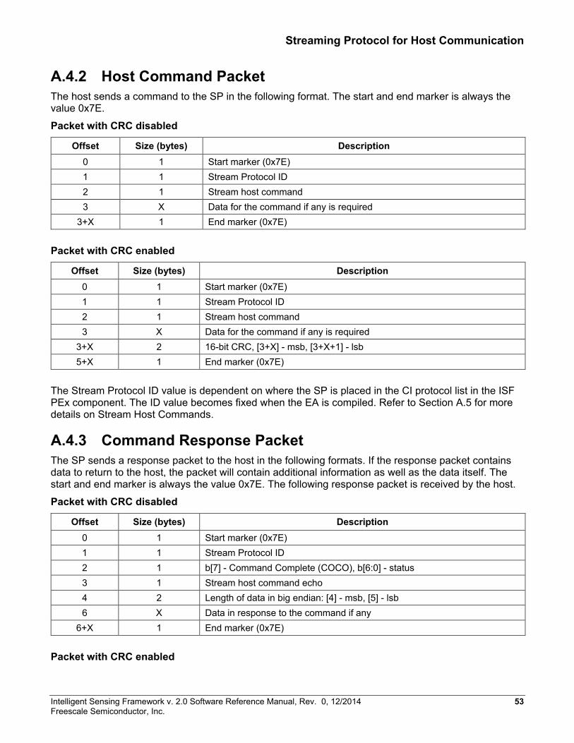
Streaming Protocol for Host Communication
A.4.2 Host Command Packet The host sends a command to the SP in the following format. The start and end marker is always the value 0x7E.
Packet with CRC disabled
Offset Size (bytes) Description 0 1 Start marker (0x7E) 1 1 Stream Protocol ID 2 1 Stream host command 3 X Data for the command if any is required
3+X 1 End marker (0x7E)
Packet with CRC enabled
Offset Size (bytes) Description 0 1 Start marker (0x7E) 1 1 Stream Protocol ID 2 1 Stream host command 3 X Data for the command if any is required
3+X 2 16-bit CRC, [3+X] - msb, [3+X+1] - lsb 5+X 1 End marker (0x7E)
The Stream Protocol ID value is dependent on where the SP is placed in the CI protocol list in the ISF PEx component. The ID value becomes fixed when the EA is compiled. Refer to Section A.5 for more details on Stream Host Commands.
A.4.3 Command Response Packet The SP sends a response packet to the host in the following formats. If the response packet contains data to return to the host, the packet will contain additional information as well as the data itself. The start and end marker is always the value 0x7E. The following response packet is received by the host.
Packet with CRC disabled
Offset Size (bytes) Description 0 1 Start marker (0x7E) 1 1 Stream Protocol ID 2 1 b[7] - Command Complete (COCO), b[6:0] - status 3 1 Stream host command echo 4 2 Length of data in big endian: [4] - msb, [5] - lsb 6 X Data in response to the command if any
6+X 1 End marker (0x7E)
Packet with CRC enabled
Intelligent Sensing Framework v. 2.0 Software Reference Manual, Rev. 0, 12/2014 53 Freescale Semiconductor, Inc.
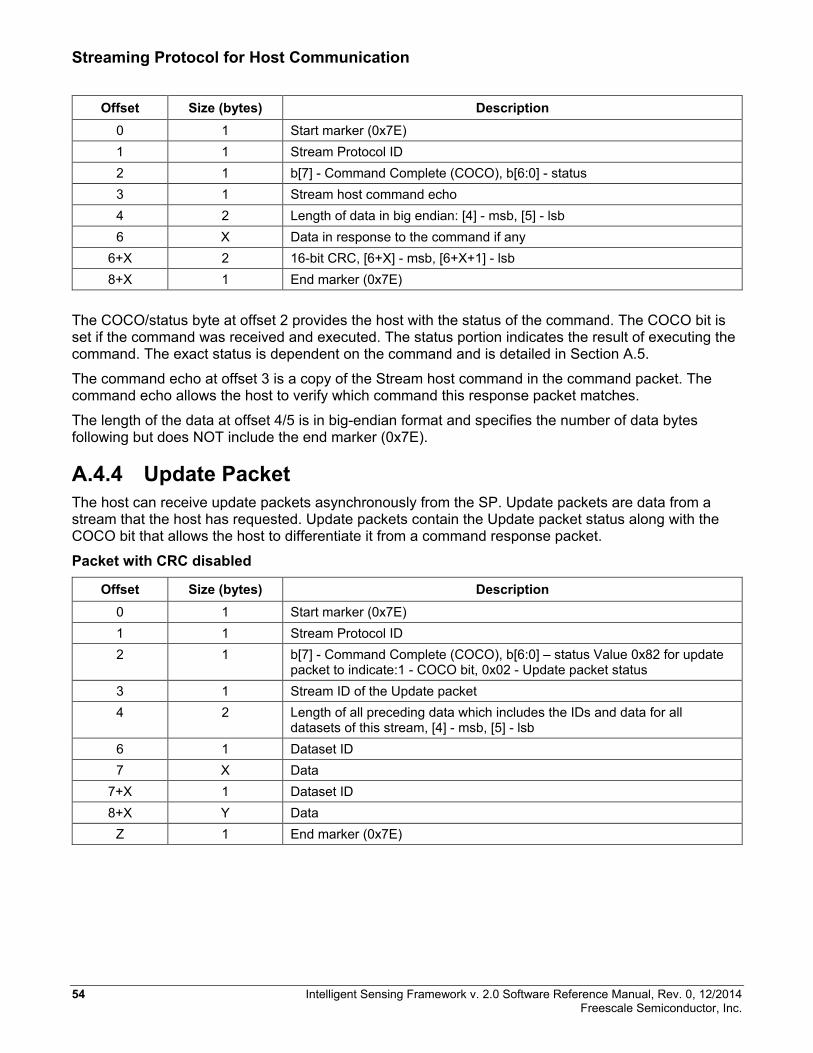
Streaming Protocol for Host Communication
Offset Size (bytes) Description 0 1 Start marker (0x7E) 1 1 Stream Protocol ID 2 1 b[7] - Command Complete (COCO), b[6:0] - status 3 1 Stream host command echo 4 2 Length of data in big endian: [4] - msb, [5] - lsb 6 X Data in response to the command if any
6+X 2 16-bit CRC, [6+X] - msb, [6+X+1] - lsb 8+X 1 End marker (0x7E)
The COCO/status byte at offset 2 provides the host with the status of the command. The COCO bit is set if the command was received and executed. The status portion indicates the result of executing the command. The exact status is dependent on the command and is detailed in Section A.5.
The command echo at offset 3 is a copy of the Stream host command in the command packet. The command echo allows the host to verify which command this response packet matches.
The length of the data at offset 4/5 is in big-endian format and specifies the number of data bytes following but does NOT include the end marker (0x7E).
A.4.4 Update Packet The host can receive update packets asynchronously from the SP. Update packets are data from a stream that the host has requested. Update packets contain the Update packet status along with the COCO bit that allows the host to differentiate it from a command response packet.
Packet with CRC disabled
Offset Size (bytes) Description 0 1 Start marker (0x7E) 1 1 Stream Protocol ID 2 1 b[7] - Command Complete (COCO), b[6:0] – status Value 0x82 for update
packet to indicate:1 - COCO bit, 0x02 - Update packet status 3 1 Stream ID of the Update packet 4 2 Length of all preceding data which includes the IDs and data for all
datasets of this stream, [4] - msb, [5] - lsb 6 1 Dataset ID 7 X Data
7+X 1 Dataset ID 8+X Y Data
Z 1 End marker (0x7E)
54 Intelligent Sensing Framework v. 2.0 Software Reference Manual, Rev. 0, 12/2014 Freescale Semiconductor, Inc.
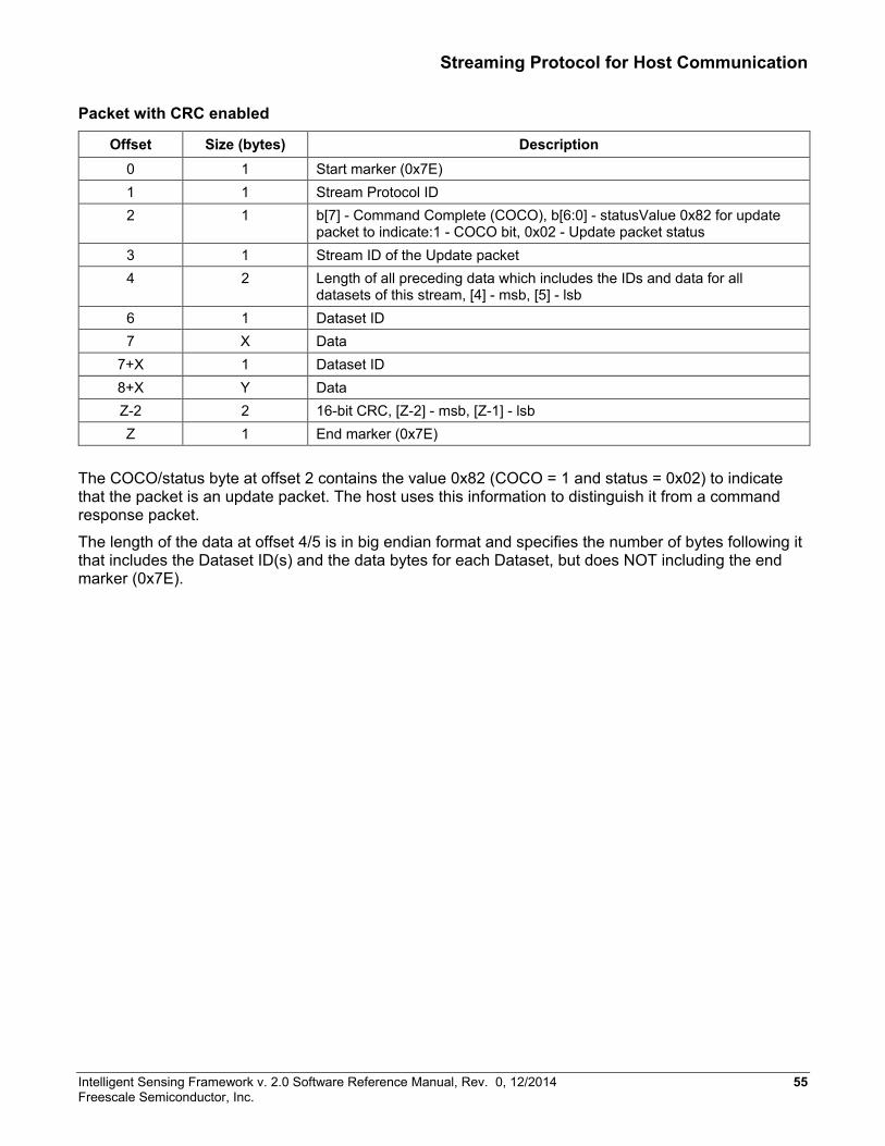
Streaming Protocol for Host Communication
Packet with CRC enabled
Offset Size (bytes) Description 0 1 Start marker (0x7E) 1 1 Stream Protocol ID 2 1 b[7] - Command Complete (COCO), b[6:0] - statusValue 0x82 for update
packet to indicate:1 - COCO bit, 0x02 - Update packet status 3 1 Stream ID of the Update packet 4 2 Length of all preceding data which includes the IDs and data for all
datasets of this stream, [4] - msb, [5] - lsb 6 1 Dataset ID 7 X Data
7+X 1 Dataset ID 8+X Y Data Z-2 2 16-bit CRC, [Z-2] - msb, [Z-1] - lsb Z 1 End marker (0x7E)
The COCO/status byte at offset 2 contains the value 0x82 (COCO = 1 and status = 0x02) to indicate that the packet is an update packet. The host uses this information to distinguish it from a command response packet.
The length of the data at offset 4/5 is in big endian format and specifies the number of bytes following it that includes the Dataset ID(s) and the data bytes for each Dataset, but does NOT including the end marker (0x7E).
Intelligent Sensing Framework v. 2.0 Software Reference Manual, Rev. 0, 12/2014 55 Freescale Semiconductor, Inc.
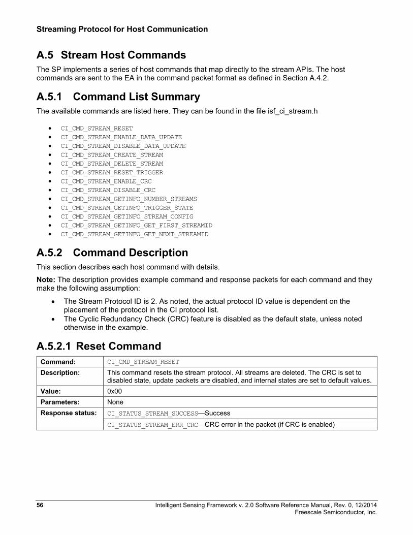
Streaming Protocol for Host Communication
A.5 Stream Host Commands The SP implements a series of host commands that map directly to the stream APIs. The host commands are sent to the EA in the command packet format as defined in Section A.4.2.
A.5.1 Command List Summary The available commands are listed here. They can be found in the file isf_ci_stream.h
• CI_CMD_STREAM_RESET • CI_CMD_STREAM_ENABLE_DATA_UPDATE • CI_CMD_STREAM_DISABLE_DATA_UPDATE • CI_CMD_STREAM_CREATE_STREAM • CI_CMD_STREAM_DELETE_STREAM • CI_CMD_STREAM_RESET_TRIGGER • CI_CMD_STREAM_ENABLE_CRC • CI_CMD_STREAM_DISABLE_CRC • CI_CMD_STREAM_GETINFO_NUMBER_STREAMS • CI_CMD_STREAM_GETINFO_TRIGGER_STATE • CI_CMD_STREAM_GETINFO_STREAM_CONFIG • CI_CMD_STREAM_GETINFO_GET_FIRST_STREAMID • CI_CMD_STREAM_GETINFO_GET_NEXT_STREAMID
A.5.2 Command Description This section describes each host command with details.
Note: The description provides example command and response packets for each command and they make the following assumption:
• The Stream Protocol ID is 2. As noted, the actual protocol ID value is dependent on the placement of the protocol in the CI protocol list.
• The Cyclic Redundancy Check (CRC) feature is disabled as the default state, unless noted otherwise in the example.
A.5.2.1 Reset Command Command: CI_CMD_STREAM_RESET
Description: This command resets the stream protocol. All streams are deleted. The CRC is set to disabled state, update packets are disabled, and internal states are set to default values.
Value: 0x00 Parameters: None Response status: CI_STATUS_STREAM_SUCCESS—Success
CI_STATUS_STREAM_ERR_CRC—CRC error in the packet (if CRC is enabled)
56 Intelligent Sensing Framework v. 2.0 Software Reference Manual, Rev. 0, 12/2014 Freescale Semiconductor, Inc.
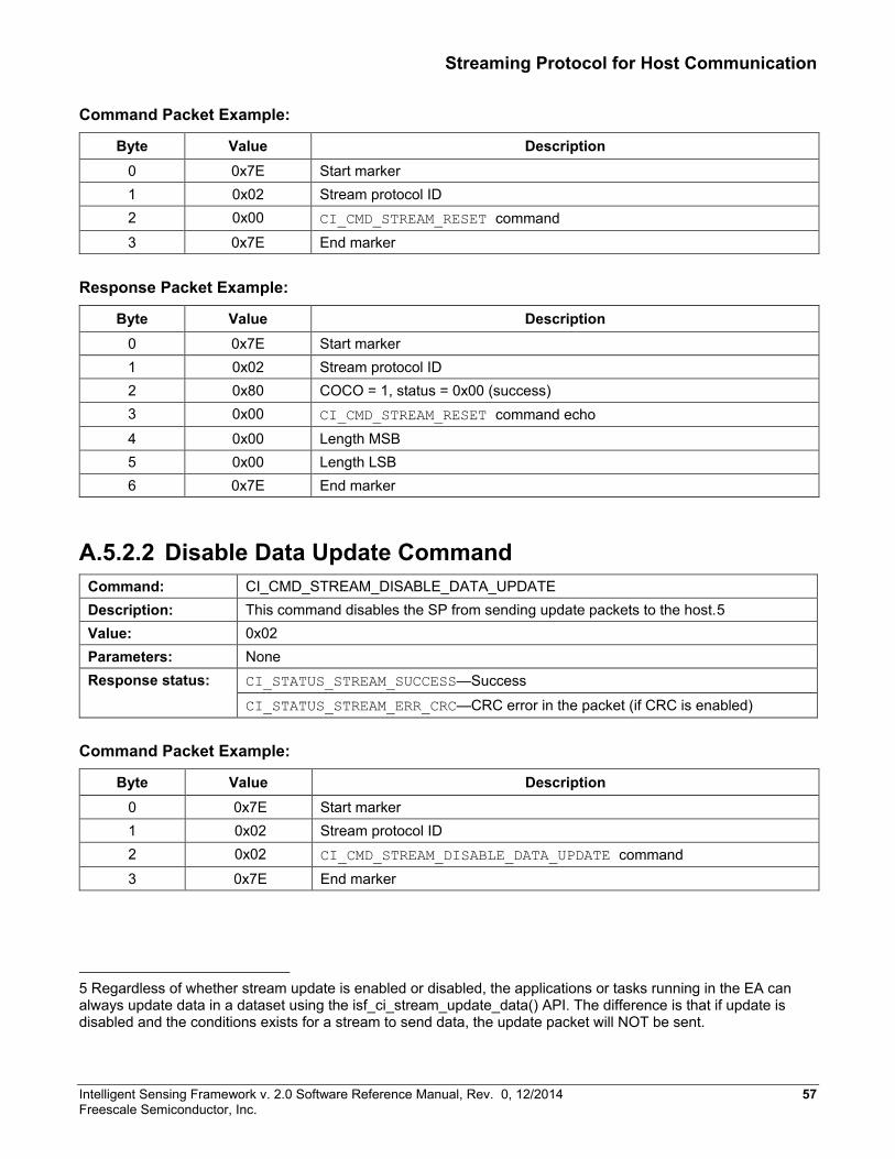
Streaming Protocol for Host Communication
Command Packet Example:
Byte Value Description 0 0x7E Start marker 1 0x02 Stream protocol ID 2 0x00 CI_CMD_STREAM_RESET command 3 0x7E End marker
Response Packet Example:
Byte Value Description 0 0x7E Start marker 1 0x02 Stream protocol ID 2 0x80 COCO = 1, status = 0x00 (success) 3 0x00 CI_CMD_STREAM_RESET command echo 4 0x00 Length MSB 5 0x00 Length LSB 6 0x7E End marker
A.5.2.2 Disable Data Update Command Command: CI_CMD_STREAM_DISABLE_DATA_UPDATE Description: This command disables the SP from sending update packets to the host.5 Value: 0x02 Parameters: None Response status: CI_STATUS_STREAM_SUCCESS—Success
CI_STATUS_STREAM_ERR_CRC—CRC error in the packet (if CRC is enabled)
Command Packet Example:
Byte Value Description 0 0x7E Start marker 1 0x02 Stream protocol ID 2 0x02 CI_CMD_STREAM_DISABLE_DATA_UPDATE command 3 0x7E End marker
5 Regardless of whether stream update is enabled or disabled, the applications or tasks running in the EA can always update data in a dataset using the isf_ci_stream_update_data() API. The difference is that if update is disabled and the conditions exists for a stream to send data, the update packet will NOT be sent.
Intelligent Sensing Framework v. 2.0 Software Reference Manual, Rev. 0, 12/2014 57 Freescale Semiconductor, Inc.
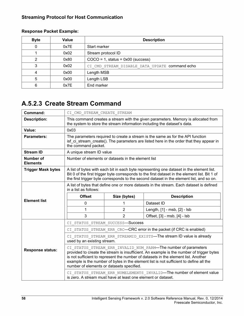
Streaming Protocol for Host Communication
Response Packet Example:
Byte Value Description 0 0x7E Start marker 1 0x02 Stream protocol ID 2 0x80 COCO = 1, status = 0x00 (success) 3 0x02 CI_CMD_STREAM_DISABLE_DATA_UPDATE command echo 4 0x00 Length MSB 5 0x00 Length LSB 6 0x7E End marker
A.5.2.3 Create Stream Command Command: CI_CMD_STREAM_CREATE_STREAM
Description: This command creates a stream with the given parameters. Memory is allocated from the system to store the stream information including the dataset’s data.
Value: 0x03 Parameters: The parameters required to create a stream is the same as for the API function
isf_ci_stream_create(). The parameters are listed here in the order that they appear in the command packet.
Stream ID A unique stream ID value Number of Elements
Number of elements or datasets in the element list
Trigger Mask bytes A list of bytes with each bit in each byte representing one dataset in the element list. Bit 0 of the first trigger byte corresponds to the first dataset in the element list. Bit 1 of the first trigger byte corresponds to the second dataset in the element list, and so on.
Element list
A list of bytes that define one or more datasets in the stream. Each dataset is defined in a list as follows:
Offset Size (bytes) Description 0 1 Dataset ID 1 2 Length, [1] - msb, [2] - lsb 3 2 Offset, [3] - msb, [4] - lsb
Response status:
CI_STATUS_STREAM_SUCCESS—Success
CI_STATUS_STREAM_ERR_CRC—CRC error in the packet (if CRC is enabled)
CI_STATUS_STREAM_ERR_STREAMID_EXISTS—The stream ID value is already used by an existing stream. CI_STATUS_STREAM_ERR_INVALID_NUM_PARM—The number of parameters provided to create the stream is insufficient. An example is the number of trigger bytes is not sufficient to represent the number of datasets in the element list. Another example is the number of bytes in the element list is not sufficient to define all the number of elements or datasets specified. CI_STATUS_STREAM_ERR_NUMELEMENTS_INVALID—The number of element value is zero. A stream must have at least one element or dataset.
58 Intelligent Sensing Framework v. 2.0 Software Reference Manual, Rev. 0, 12/2014 Freescale Semiconductor, Inc.
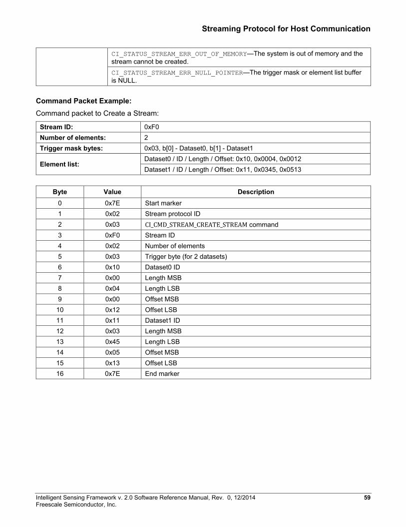
Streaming Protocol for Host Communication
CI_STATUS_STREAM_ERR_OUT_OF_MEMORY—The system is out of memory and the stream cannot be created. CI_STATUS_STREAM_ERR_NULL_POINTER—The trigger mask or element list buffer is NULL.
Command Packet Example: Command packet to Create a Stream:
Stream ID: 0xF0 Number of elements: 2 Trigger mask bytes: 0x03, b[0] - Dataset0, b[1] - Dataset1
Element list: Dataset0 / ID / Length / Offset: 0x10, 0x0004, 0x0012 Dataset1 / ID / Length / Offset: 0x11, 0x0345, 0x0513
Byte Value Description
0 0x7E Start marker 1 0x02 Stream protocol ID 2 0x03 CI_CMD_STREAM_CREATE_STREAM command 3 0xF0 Stream ID 4 0x02 Number of elements 5 0x03 Trigger byte (for 2 datasets) 6 0x10 Dataset0 ID 7 0x00 Length MSB 8 0x04 Length LSB 9 0x00 Offset MSB 10 0x12 Offset LSB 11 0x11 Dataset1 ID 12 0x03 Length MSB 13 0x45 Length LSB 14 0x05 Offset MSB 15 0x13 Offset LSB 16 0x7E End marker
Intelligent Sensing Framework v. 2.0 Software Reference Manual, Rev. 0, 12/2014 59 Freescale Semiconductor, Inc.
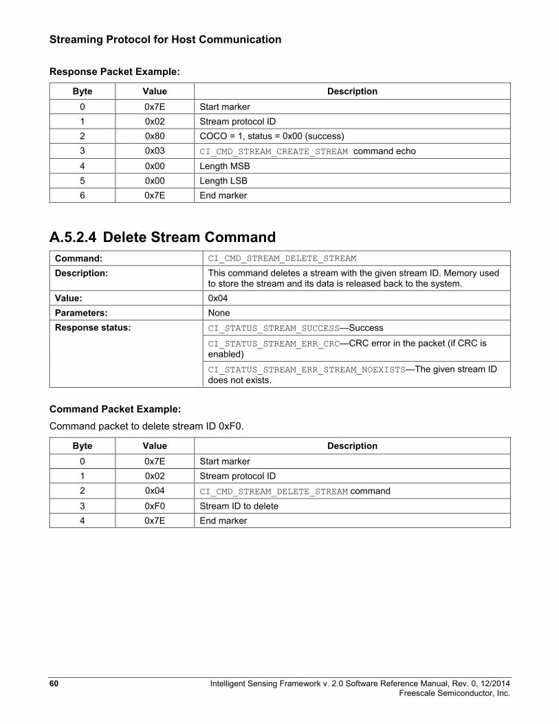
Streaming Protocol for Host Communication
Response Packet Example:
Byte Value Description 0 0x7E Start marker 1 0x02 Stream protocol ID 2 0x80 COCO = 1, status = 0x00 (success) 3 0x03 CI_CMD_STREAM_CREATE_STREAM command echo 4 0x00 Length MSB 5 0x00 Length LSB 6 0x7E End marker
A.5.2.4 Delete Stream Command Command: CI_CMD_STREAM_DELETE_STREAM
Description: This command deletes a stream with the given stream ID. Memory used to store the stream and its data is released back to the system.
Value: 0x04 Parameters: None Response status: CI_STATUS_STREAM_SUCCESS—Success
CI_STATUS_STREAM_ERR_CRC—CRC error in the packet (if CRC is enabled) CI_STATUS_STREAM_ERR_STREAM_NOEXISTS—The given stream ID does not exists.
Command Packet Example: Command packet to delete stream ID 0xF0.
Byte Value Description 0 0x7E Start marker 1 0x02 Stream protocol ID 2 0x04 CI_CMD_STREAM_DELETE_STREAM command 3 0xF0 Stream ID to delete 4 0x7E End marker
60 Intelligent Sensing Framework v. 2.0 Software Reference Manual, Rev. 0, 12/2014 Freescale Semiconductor, Inc.
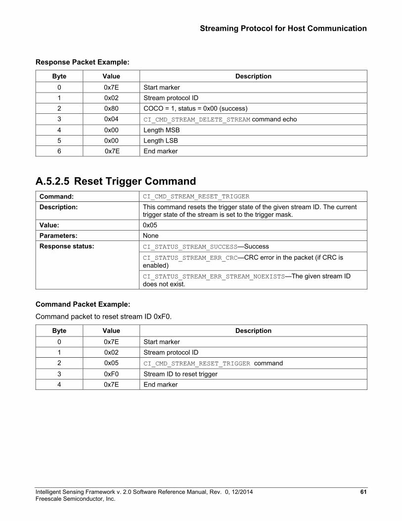
Streaming Protocol for Host Communication
Response Packet Example:
Byte Value Description 0 0x7E Start marker 1 0x02 Stream protocol ID 2 0x80 COCO = 1, status = 0x00 (success) 3 0x04 CI_CMD_STREAM_DELETE_STREAM command echo 4 0x00 Length MSB 5 0x00 Length LSB 6 0x7E End marker
A.5.2.5 Reset Trigger Command Command: CI_CMD_STREAM_RESET_TRIGGER
Description: This command resets the trigger state of the given stream ID. The current trigger state of the stream is set to the trigger mask.
Value: 0x05 Parameters: None Response status: CI_STATUS_STREAM_SUCCESS—Success
CI_STATUS_STREAM_ERR_CRC—CRC error in the packet (if CRC is enabled) CI_STATUS_STREAM_ERR_STREAM_NOEXISTS—The given stream ID does not exist.
Command Packet Example: Command packet to reset stream ID 0xF0.
Byte Value Description 0 0x7E Start marker 1 0x02 Stream protocol ID 2 0x05 CI_CMD_STREAM_RESET_TRIGGER command 3 0xF0 Stream ID to reset trigger 4 0x7E End marker
Intelligent Sensing Framework v. 2.0 Software Reference Manual, Rev. 0, 12/2014 61 Freescale Semiconductor, Inc.
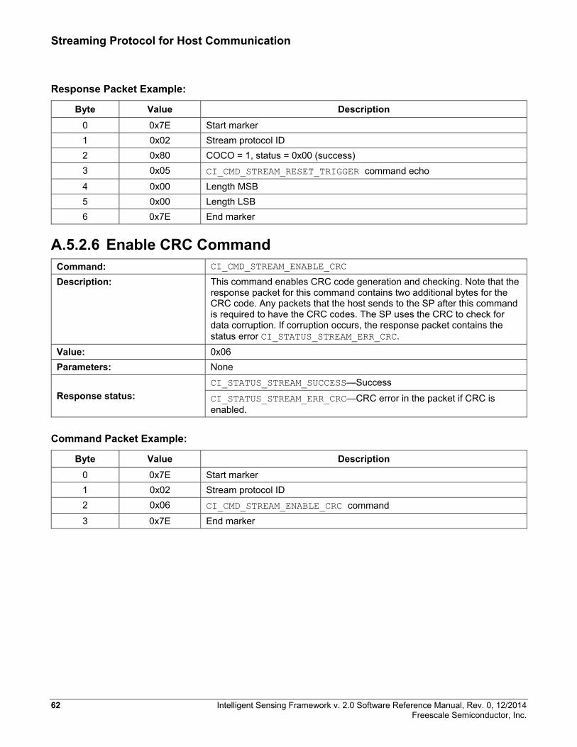
Streaming Protocol for Host Communication
Response Packet Example:
Byte Value Description 0 0x7E Start marker 1 0x02 Stream protocol ID 2 0x80 COCO = 1, status = 0x00 (success) 3 0x05 CI_CMD_STREAM_RESET_TRIGGER command echo 4 0x00 Length MSB 5 0x00 Length LSB 6 0x7E End marker
A.5.2.6 Enable CRC Command Command: CI_CMD_STREAM_ENABLE_CRC
Description: This command enables CRC code generation and checking. Note that the response packet for this command contains two additional bytes for the CRC code. Any packets that the host sends to the SP after this command is required to have the CRC codes. The SP uses the CRC to check for data corruption. If corruption occurs, the response packet contains the status error CI_STATUS_STREAM_ERR_CRC.
Value: 0x06 Parameters: None
Response status: CI_STATUS_STREAM_SUCCESS—Success
CI_STATUS_STREAM_ERR_CRC—CRC error in the packet if CRC is enabled.
Command Packet Example:
Byte Value Description 0 0x7E Start marker 1 0x02 Stream protocol ID 2 0x06 CI_CMD_STREAM_ENABLE_CRC command 3 0x7E End marker
62 Intelligent Sensing Framework v. 2.0 Software Reference Manual, Rev. 0, 12/2014 Freescale Semiconductor, Inc.
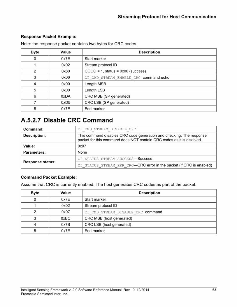
Streaming Protocol for Host Communication
Response Packet Example: Note: the response packet contains two bytes for CRC codes.
Byte Value Description 0 0x7E Start marker 1 0x02 Stream protocol ID 2 0x80 COCO = 1, status = 0x00 (success) 3 0x06 CI_CMD_STREAM_ENABLE_CRC command echo 4 0x00 Length MSB 5 0x00 Length LSB 6 0xDA CRC MSB (SP generated) 7 0xD5 CRC LSB (SP generated) 8 0x7E End marker
A.5.2.7 Disable CRC Command Command: CI_CMD_STREAM_DISABLE_CRC
Description: This command disables CRC code generation and checking. The response packet for this command does NOT contain CRC codes as it is disabled.
Value: 0x07 Parameters: None
Response status: CI_STATUS_STREAM_SUCCESS—Success
CI_STATUS_STREAM_ERR_CRC—CRC error in the packet (if CRC is enabled)
Command Packet Example: Assume that CRC is currently enabled. The host generates CRC codes as part of the packet.
Byte Value Description 0 0x7E Start marker 1 0x02 Stream protocol ID 2 0x07 CI_CMD_STREAM_DISABLE_CRC command 3 0xBC CRC MSB (host generated) 4 0x7B CRC LSB (host generated) 5 0x7E End marker
Intelligent Sensing Framework v. 2.0 Software Reference Manual, Rev. 0, 12/2014 63 Freescale Semiconductor, Inc.
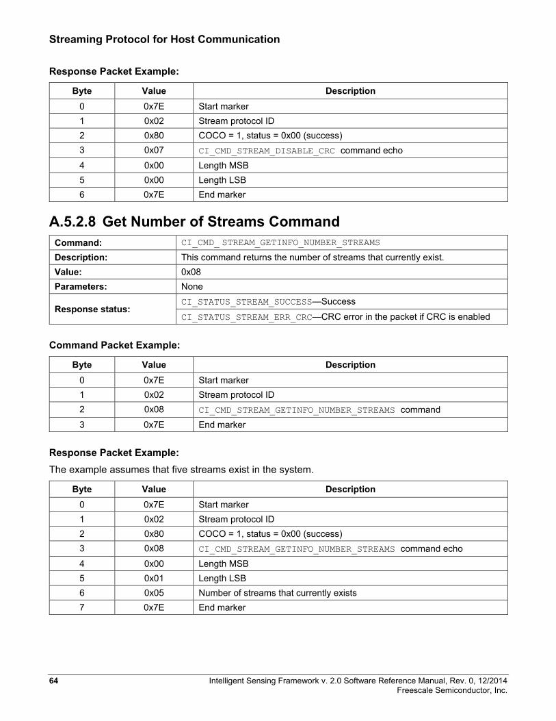
Streaming Protocol for Host Communication
Response Packet Example:
Byte Value Description 0 0x7E Start marker 1 0x02 Stream protocol ID 2 0x80 COCO = 1, status = 0x00 (success) 3 0x07 CI_CMD_STREAM_DISABLE_CRC command echo 4 0x00 Length MSB 5 0x00 Length LSB 6 0x7E End marker
A.5.2.8 Get Number of Streams Command Command: CI_CMD_ STREAM_GETINFO_NUMBER_STREAMS
Description: This command returns the number of streams that currently exist. Value: 0x08 Parameters: None
Response status: CI_STATUS_STREAM_SUCCESS—Success
CI_STATUS_STREAM_ERR_CRC—CRC error in the packet if CRC is enabled
Command Packet Example:
Byte Value Description 0 0x7E Start marker 1 0x02 Stream protocol ID 2 0x08 CI_CMD_STREAM_GETINFO_NUMBER_STREAMS command 3 0x7E End marker
Response Packet Example: The example assumes that five streams exist in the system.
Byte Value Description 0 0x7E Start marker 1 0x02 Stream protocol ID 2 0x80 COCO = 1, status = 0x00 (success) 3 0x08 CI_CMD_STREAM_GETINFO_NUMBER_STREAMS command echo 4 0x00 Length MSB 5 0x01 Length LSB 6 0x05 Number of streams that currently exists 7 0x7E End marker
64 Intelligent Sensing Framework v. 2.0 Software Reference Manual, Rev. 0, 12/2014 Freescale Semiconductor, Inc.
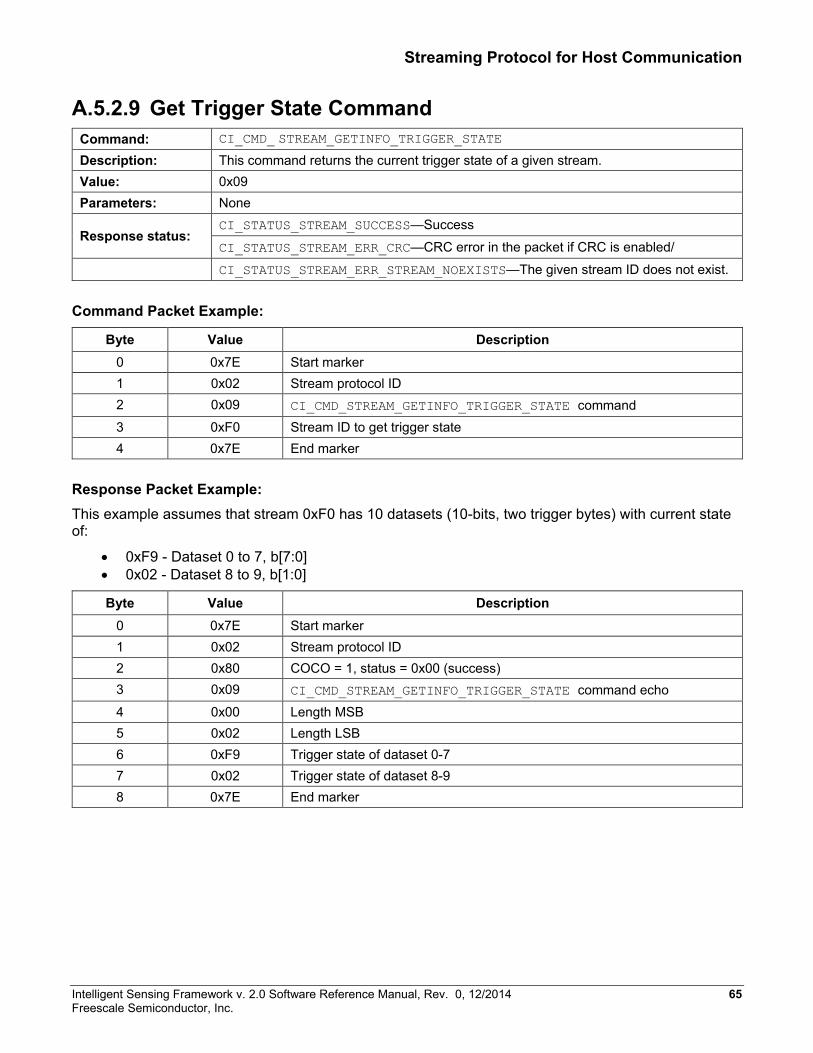
Streaming Protocol for Host Communication
A.5.2.9 Get Trigger State Command Command: CI_CMD_ STREAM_GETINFO_TRIGGER_STATE
Description: This command returns the current trigger state of a given stream. Value: 0x09 Parameters: None
Response status: CI_STATUS_STREAM_SUCCESS—Success
CI_STATUS_STREAM_ERR_CRC—CRC error in the packet if CRC is enabled/ CI_STATUS_STREAM_ERR_STREAM_NOEXISTS—The given stream ID does not exist.
Command Packet Example:
Byte Value Description 0 0x7E Start marker 1 0x02 Stream protocol ID 2 0x09 CI_CMD_STREAM_GETINFO_TRIGGER_STATE command 3 0xF0 Stream ID to get trigger state 4 0x7E End marker
Response Packet Example: This example assumes that stream 0xF0 has 10 datasets (10-bits, two trigger bytes) with current state of:
• 0xF9 - Dataset 0 to 7, b[7:0] • 0x02 - Dataset 8 to 9, b[1:0]
Byte Value Description 0 0x7E Start marker 1 0x02 Stream protocol ID 2 0x80 COCO = 1, status = 0x00 (success) 3 0x09 CI_CMD_STREAM_GETINFO_TRIGGER_STATE command echo 4 0x00 Length MSB 5 0x02 Length LSB 6 0xF9 Trigger state of dataset 0-7 7 0x02 Trigger state of dataset 8-9 8 0x7E End marker
Intelligent Sensing Framework v. 2.0 Software Reference Manual, Rev. 0, 12/2014 65 Freescale Semiconductor, Inc.
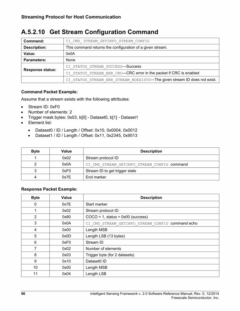
Streaming Protocol for Host Communication
A.5.2.10 Get Stream Configuration Command Command: CI_CMD_ STREAM_GETINFO_STREAM_CONFIG
Description: This command returns the configuration of a given stream. Value: 0x0A Parameters: None
Response status: CI_STATUS_STREAM_SUCCESS—Success
CI_STATUS_STREAM_ERR_CRC—CRC error in the packet if CRC is enabled CI_STATUS_STREAM_ERR_STREAM_NOEXISTS—The given stream ID does not exist.
Command Packet Example: Assume that a stream exists with the following attributes:
• Stream ID: 0xF0 • Number of elements: 2 • Trigger mask bytes: 0x03, b[0] - Dataset0, b[1] - Dataset1 • Element list:
• Dataset0 / ID / Length / Offset: 0x10, 0x0004, 0x0012 • Dataset1 / ID / Length / Offset: 0x11, 0x2345, 0x9513
Byte Value Description 1 0x02 Stream protocol ID 2 0x0A CI_CMD_STREAM_GETINFO_STREAM_CONFIG command 3 0xF0 Stream ID to get trigger state 4 0x7E End marker
Response Packet Example:
Byte Value Description 0 0x7E Start marker 1 0x02 Stream protocol ID 2 0x80 COCO = 1, status = 0x00 (success) 3 0x0A CI_CMD_STREAM_GETINFO_STREAM_CONFIG command echo 4 0x00 Length MSB 5 0x0D Length LSB (13 bytes) 6 0xF0 Stream ID 7 0x02 Number of elements 8 0x03 Trigger byte (for 2 datasets) 9 0x10 Dataset0 ID 10 0x00 Length MSB 11 0x04 Length LSB
66 Intelligent Sensing Framework v. 2.0 Software Reference Manual, Rev. 0, 12/2014 Freescale Semiconductor, Inc.
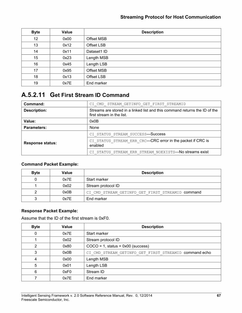
Streaming Protocol for Host Communication
Byte Value Description 12 0x00 Offset MSB 13 0x12 Offset LSB 14 0x11 Dataset1 ID 15 0x23 Length MSB 16 0x45 Length LSB 17 0x95 Offset MSB 18 0x13 Offset LSB 19 0x7E End marker
A.5.2.11 Get First Stream ID Command Command: CI_CMD_ STREAM_GETINFO_GET_FIRST_STREAMID
Description: Streams are stored in a linked list and this command returns the ID of the first stream in the list.
Value: 0x0B Parameters: None
Response status:
CI_STATUS_STREAM_SUCCESS—Success
CI_STATUS_STREAM_ERR_CRC—CRC error in the packet if CRC is enabled CI_STATUS_STREAM_ERR_STREAM_NOEXISTS—No streams exist
Command Packet Example:
Byte Value Description 0 0x7E Start marker 1 0x02 Stream protocol ID 2 0x0B CI_CMD_STREAM_GETINFO_GET_FIRST_STREAMID command 3 0x7E End marker
Response Packet Example: Assume that the ID of the first stream is 0xF0.
Byte Value Description 0 0x7E Start marker 1 0x02 Stream protocol ID 2 0x80 COCO = 1, status = 0x00 (success) 3 0x0B CI_CMD_STREAM_GETINFO_GET_FIRST_STREAMID command echo 4 0x00 Length MSB 5 0x01 Length LSB 6 0xF0 Stream ID 7 0x7E End marker
Intelligent Sensing Framework v. 2.0 Software Reference Manual, Rev. 0, 12/2014 67 Freescale Semiconductor, Inc.
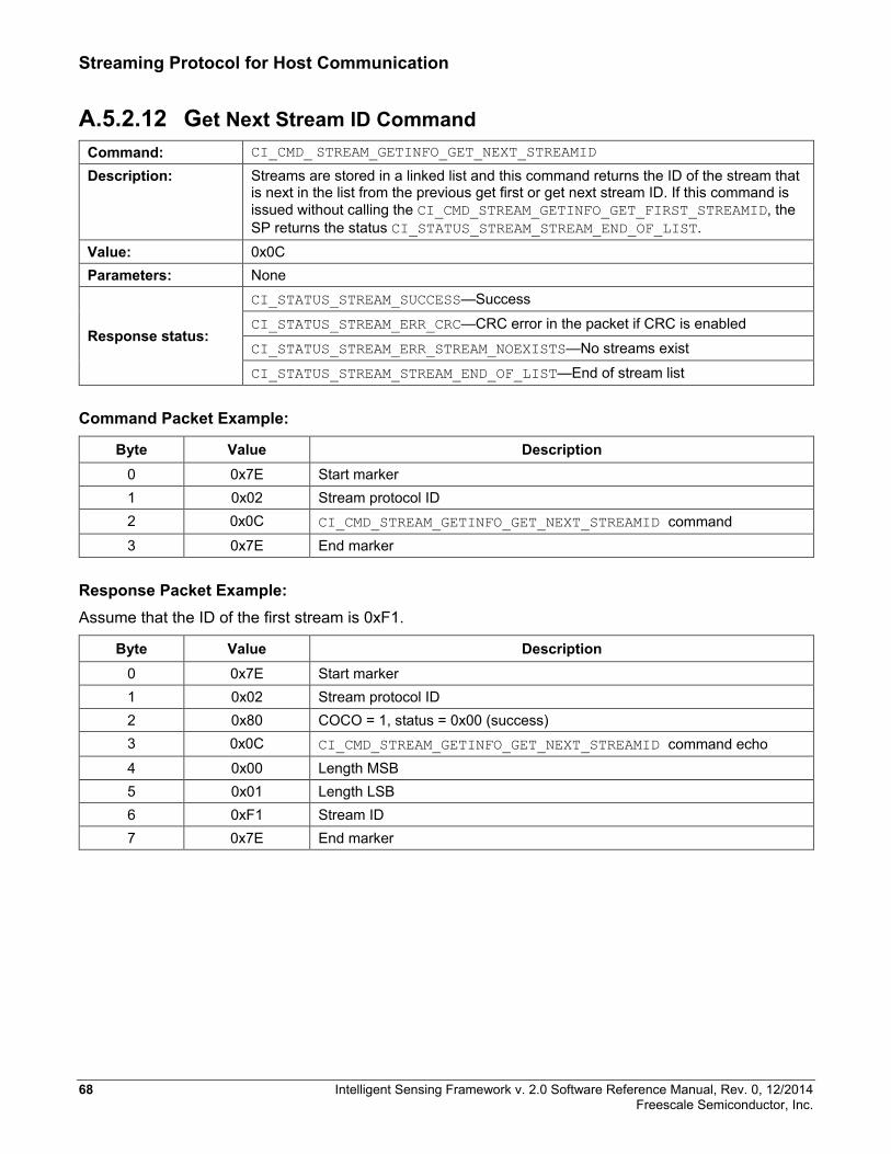
Streaming Protocol for Host Communication
A.5.2.12 Get Next Stream ID Command Command: CI_CMD_ STREAM_GETINFO_GET_NEXT_STREAMID
Description: Streams are stored in a linked list and this command returns the ID of the stream that is next in the list from the previous get first or get next stream ID. If this command is issued without calling the CI_CMD_STREAM_GETINFO_GET_FIRST_STREAMID, the SP returns the status CI_STATUS_STREAM_STREAM_END_OF_LIST.
Value: 0x0C Parameters: None
Response status:
CI_STATUS_STREAM_SUCCESS—Success
CI_STATUS_STREAM_ERR_CRC—CRC error in the packet if CRC is enabled
CI_STATUS_STREAM_ERR_STREAM_NOEXISTS—No streams exist
CI_STATUS_STREAM_STREAM_END_OF_LIST—End of stream list
Command Packet Example:
Byte Value Description 0 0x7E Start marker 1 0x02 Stream protocol ID 2 0x0C CI_CMD_STREAM_GETINFO_GET_NEXT_STREAMID command 3 0x7E End marker
Response Packet Example: Assume that the ID of the first stream is 0xF1.
Byte Value Description 0 0x7E Start marker 1 0x02 Stream protocol ID 2 0x80 COCO = 1, status = 0x00 (success) 3 0x0C CI_CMD_STREAM_GETINFO_GET_NEXT_STREAMID command echo 4 0x00 Length MSB 5 0x01 Length LSB 6 0xF1 Stream ID 7 0x7E End marker
68 Intelligent Sensing Framework v. 2.0 Software Reference Manual, Rev. 0, 12/2014 Freescale Semiconductor, Inc.
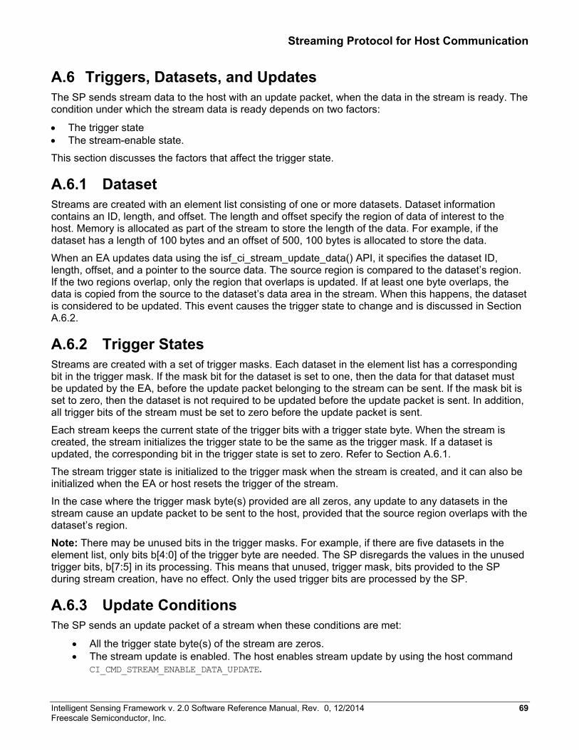
Streaming Protocol for Host Communication
A.6 Triggers, Datasets, and Updates The SP sends stream data to the host with an update packet, when the data in the stream is ready. The condition under which the stream data is ready depends on two factors:
• The trigger state • The stream-enable state.
This section discusses the factors that affect the trigger state.
A.6.1 Dataset Streams are created with an element list consisting of one or more datasets. Dataset information contains an ID, length, and offset. The length and offset specify the region of data of interest to the host. Memory is allocated as part of the stream to store the length of the data. For example, if the dataset has a length of 100 bytes and an offset of 500, 100 bytes is allocated to store the data.
When an EA updates data using the isf_ci_stream_update_data() API, it specifies the dataset ID, length, offset, and a pointer to the source data. The source region is compared to the dataset’s region. If the two regions overlap, only the region that overlaps is updated. If at least one byte overlaps, the data is copied from the source to the dataset’s data area in the stream. When this happens, the dataset is considered to be updated. This event causes the trigger state to change and is discussed in Section A.6.2.
A.6.2 Trigger States Streams are created with a set of trigger masks. Each dataset in the element list has a corresponding bit in the trigger mask. If the mask bit for the dataset is set to one, then the data for that dataset must be updated by the EA, before the update packet belonging to the stream can be sent. If the mask bit is set to zero, then the dataset is not required to be updated before the update packet is sent. In addition, all trigger bits of the stream must be set to zero before the update packet is sent.
Each stream keeps the current state of the trigger bits with a trigger state byte. When the stream is created, the stream initializes the trigger state to be the same as the trigger mask. If a dataset is updated, the corresponding bit in the trigger state is set to zero. Refer to Section A.6.1.
The stream trigger state is initialized to the trigger mask when the stream is created, and it can also be initialized when the EA or host resets the trigger of the stream.
In the case where the trigger mask byte(s) provided are all zeros, any update to any datasets in the stream cause an update packet to be sent to the host, provided that the source region overlaps with the dataset’s region.
Note: There may be unused bits in the trigger masks. For example, if there are five datasets in the element list, only bits b[4:0] of the trigger byte are needed. The SP disregards the values in the unused trigger bits, b[7:5] in its processing. This means that unused, trigger mask, bits provided to the SP during stream creation, have no effect. Only the used trigger bits are processed by the SP.
A.6.3 Update Conditions The SP sends an update packet of a stream when these conditions are met:
• All the trigger state byte(s) of the stream are zeros. • The stream update is enabled. The host enables stream update by using the host command
CI_CMD_STREAM_ENABLE_DATA_UPDATE.
Intelligent Sensing Framework v. 2.0 Software Reference Manual, Rev. 0, 12/2014 69 Freescale Semiconductor, Inc.
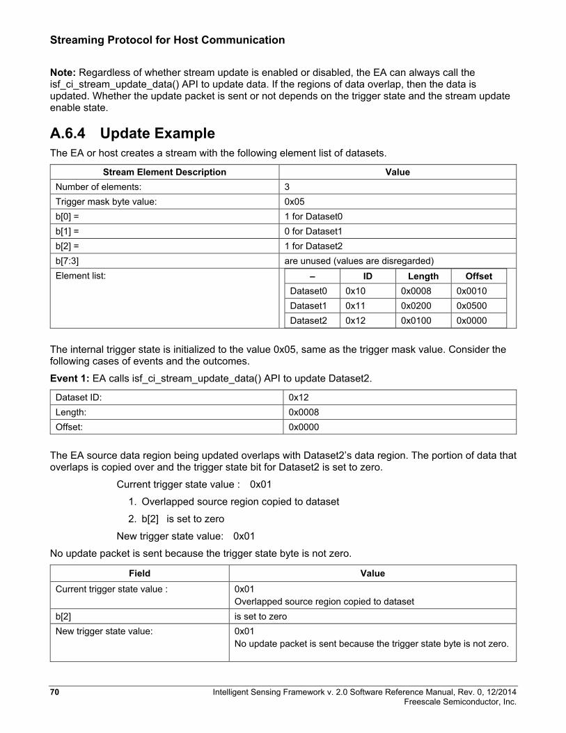
Streaming Protocol for Host Communication
Note: Regardless of whether stream update is enabled or disabled, the EA can always call the isf_ci_stream_update_data() API to update data. If the regions of data overlap, then the data is updated. Whether the update packet is sent or not depends on the trigger state and the stream update enable state.
A.6.4 Update Example The EA or host creates a stream with the following element list of datasets.
Stream Element Description Value Number of elements: 3 Trigger mask byte value: 0x05 b[0] = 1 for Dataset0 b[1] = 0 for Dataset1 b[2] = 1 for Dataset2 b[7:3] are unused (values are disregarded) Element list: – ID Length Offset
Dataset0 0x10 0x0008 0x0010 Dataset1 0x11 0x0200 0x0500 Dataset2 0x12 0x0100 0x0000
The internal trigger state is initialized to the value 0x05, same as the trigger mask value. Consider the following cases of events and the outcomes.
Event 1: EA calls isf_ci_stream_update_data() API to update Dataset2.
Dataset ID: 0x12 Length: 0x0008 Offset: 0x0000
The EA source data region being updated overlaps with Dataset2’s data region. The portion of data that overlaps is copied over and the trigger state bit for Dataset2 is set to zero.
Current trigger state value : 0x01
1. Overlapped source region copied to dataset
2. b[2] is set to zero
New trigger state value: 0x01
No update packet is sent because the trigger state byte is not zero.
Field Value Current trigger state value : 0x01
Overlapped source region copied to dataset b[2] is set to zero New trigger state value: 0x01
No update packet is sent because the trigger state byte is not zero.
70 Intelligent Sensing Framework v. 2.0 Software Reference Manual, Rev. 0, 12/2014 Freescale Semiconductor, Inc.

Streaming Protocol for Host Communication
No update packet is sent because the trigger state byte is not zero. Event 2: EA calls isf_ci_stream_update_data() API to update Dataset1.
Field Value Dataset ID: 0x11 Length: 0x0200 Offset: 0x0400
The region being updated overlaps with Dataset1’s region. Note that a portion of the EA source region being updated is outside of Dataset1’s region. In this case, only the source region that overlaps with Dataset1’s region is updated. The overlapped region starts at offset 0x500 with a length of 0x0100 bytes and only this region is copied to the dataset.
Because the trigger state bit for Dataset1 is already cleared, there is no change in the trigger state.
Current trigger state value: 0x01
1. Overlapped source region copied to dataset 2. b[1] set to 0 (already 0 so no change)
New trigger state value: 0x01
No update packet is sent because the trigger state byte is not 0.
Event 3: EA calls isf_ci_stream_update_data() API to update Dataset0.
Field Value Dataset ID: 0x10 Length: 0x0020 Offset: 0x0030
The EA source data region being updated does NOT overlap with Dataset0’s region. No data is copied. The trigger bit for Dataset0 remains a value of one.
Current trigger state value: 0x01
New trigger state value: 0x01
No update packet is sent because the trigger state byte is not 0.
Event 4: EA calls isf_ci_stream_update_data() API to update Dataset0.
Intelligent Sensing Framework v. 2.0 Software Reference Manual, Rev. 0, 12/2014 71 Freescale Semiconductor, Inc.

Streaming Protocol for Host Communication
Field Value Dataset ID: 0x10 Length: 0x004 Offset: 0x0010
The EA source data region being updated overlaps with Dataset0’s region. The source data is copied to the dataset. The trigger state bit for Dataset0 is set to zero.
Current trigger state value : 0x01
1. b[0] is set to 0 2. Trigger state value: 0x00 3. Update packet for the stream is sent to the host if stream update is enabled. 4. Trigger state is reset to the trigger mask value.
New trigger state value: 0x05
In this situation, the trigger state becomes zero after the dataset data is updated that causes an update packet to be sent if stream update is enabled. The trigger state is then reset to the trigger mask value.
A.7 Internal Design This section discusses the internal design of the SP. The stream instance and configuration are described along with the handling of the instance linked list.
A.7.1 Stream Instance Stream information is stored in a singly-linked list of stream instances. The placement of the stream in the linked list is in the order in which they are created by the EA or host. The last stream in the list points to a NULL stream. Each stream instance encapsulates the following information about the stream:
• Stream configuration that includes stream ID, trigger mask, and dataset(s) • Current trigger states • Stream buffer; for more details see Section A.7.2 • Pointer to the next stream in the linked list
The C code definition of the stream instances is as follows:
typedef struct __attribute__ ((__packed__)) _ci_stream_instance
{
ci_stream_config_t *pStreamConfig;
uint8 *pStreamBuffer;
uint8 *pTriggerState;
struct _ci_stream_instance *pNextInstance;
} ci_stream_instance_t;
72 Intelligent Sensing Framework v. 2.0 Software Reference Manual, Rev. 0, 12/2014 Freescale Semiconductor, Inc.
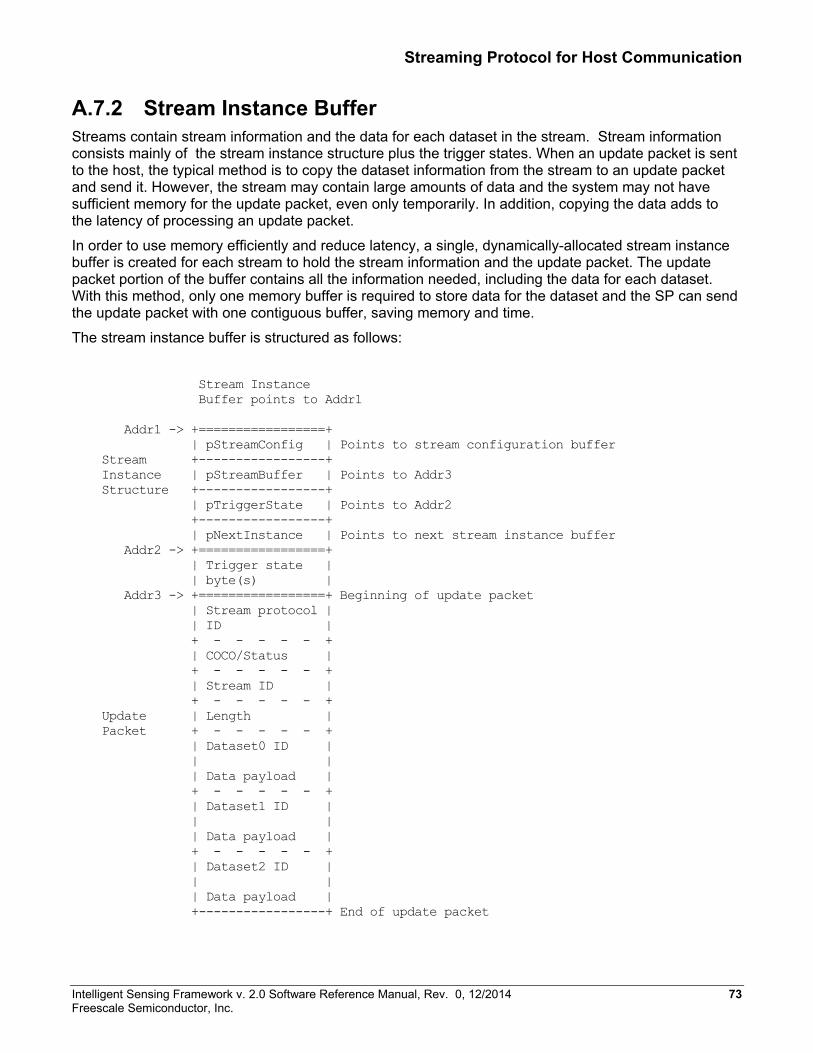
Streaming Protocol for Host Communication
A.7.2 Stream Instance Buffer Streams contain stream information and the data for each dataset in the stream. Stream information consists mainly of the stream instance structure plus the trigger states. When an update packet is sent to the host, the typical method is to copy the dataset information from the stream to an update packet and send it. However, the stream may contain large amounts of data and the system may not have sufficient memory for the update packet, even only temporarily. In addition, copying the data adds to the latency of processing an update packet.
In order to use memory efficiently and reduce latency, a single, dynamically-allocated stream instance buffer is created for each stream to hold the stream information and the update packet. The update packet portion of the buffer contains all the information needed, including the data for each dataset. With this method, only one memory buffer is required to store data for the dataset and the SP can send the update packet with one contiguous buffer, saving memory and time.
The stream instance buffer is structured as follows:
Stream Instance Buffer points to Addr1 Addr1 -> +=================+ | pStreamConfig | Points to stream configuration buffer Stream +-----------------+ Instance | pStreamBuffer | Points to Addr3 Structure +-----------------+ | pTriggerState | Points to Addr2 +-----------------+ | pNextInstance | Points to next stream instance buffer Addr2 -> +=================+ | Trigger state | | byte(s) | Addr3 -> +=================+ Beginning of update packet | Stream protocol | | ID | + - - - - - + | COCO/Status | + - - - - - + | Stream ID | + - - - - - + Update | Length | Packet + - - - - - + | Dataset0 ID | | | | Data payload | + - - - - - + | Dataset1 ID | | | | Data payload | + - - - - - + | Dataset2 ID | | | | Data payload | +-----------------+ End of update packet
Intelligent Sensing Framework v. 2.0 Software Reference Manual, Rev. 0, 12/2014 73 Freescale Semiconductor, Inc.
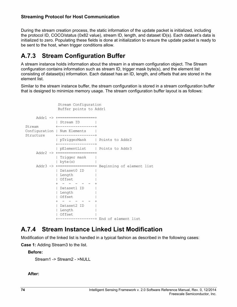
Streaming Protocol for Host Communication
During the stream creation process, the static information of the update packet is initialized, including the protocol ID, COCO/status (0x82 value), stream ID, length, and dataset ID(s). Each dataset’s data is initialized to zero. Populating these fields is done at initialization to ensure the update packet is ready to be sent to the host, when trigger conditions allow.
A.7.3 Stream Configuration Buffer A stream instance holds information about the stream in a stream configuration object. The Stream configuration contains information such as stream ID, trigger mask byte(s), and the element list consisting of dataset(s) information. Each dataset has an ID, length, and offsets that are stored in the element list.
Similar to the stream instance buffer, the stream configuration is stored in a stream configuration buffer that is designed to minimize memory usage. The stream configuration buffer layout is as follows:
Stream Configuration Buffer points to Addr1 Addr1 -> +=================+ | Stream ID | Stream +-----------------+ Configuration | Num Elements | Structure +-----------------+ | pTriggerMask | Points to Addr2 +-----------------+ | pElementList | Points to Addr3 Addr2 -> +=================+ | Trigger mask | | byte(s) | Addr3 -> +=================+ Beginning of element list | Dataset0 ID | | Length | | Offset | + - - - - - + | Dataset1 ID | | Length | | Offset | + - - - - - + | Dataset2 ID | | Length | | Offset | +-----------------+ End of element list
A.7.4 Stream Instance Linked List Modification Modification of the linked list is handled in a typical fashion as described in the following cases:
Case 1: Adding Stream3 to the list.
Before: Stream1 -> Stream2 - >NULL
After:
74 Intelligent Sensing Framework v. 2.0 Software Reference Manual, Rev. 0, 12/2014 Freescale Semiconductor, Inc.

Streaming Protocol for Host Communication
Stream1 -> Stream2 -> Stream3 -> NULL
Case 2: Deleting the first stream, Stream1, from the list.
Before: Stream1 -> Stream2 -> Stream3 -> NULL
After: Stream2 -> Stream3 -> NULL
Case 3: Deleting the middle stream, Stream2, from the list.
Before: Stream1 -> Stream2 -> Stream3 -> NULL
After: Stream1 -> Stream3 -> NULL
Intelligent Sensing Framework v. 2.0 Software Reference Manual, Rev. 0, 12/2014 75 Freescale Semiconductor, Inc.
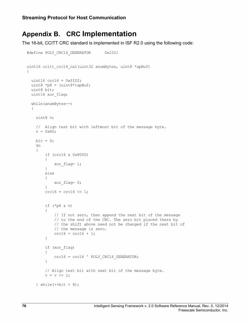
Streaming Protocol for Host Communication
Appendix B. CRC Implementation The 16-bit, CCITT CRC standard is implemented in ISF R2.0 using the following code:
#define POLY_CRC16_GENERATOR 0x1021 uint16 ccitt_crc16_cal(uint32 anumBytes, uint8 *apBuf) { uint16 crc16 = 0xffff; uint8 *p8 = (uint8*)apBuf; uint8 bit; uint16 xor_flag; while(anumBytes--) { uint8 v; // Align test bit with leftmost bit of the message byte. v = 0x80; bit = 0; do { if (crc16 & 0x8000) { xor_flag= 1; } else { xor_flag= 0; } crc16 = crc16 << 1; if (*p8 & v) { // If not zero, then append the next bit of the message // to the end of the CRC. The zero bit placed there by // the shift above need not be changed if the next bit of // the message is zero. crc16 = crc16 + 1; } if (xor_flag) { crc16 = crc16 ^ POLY_CRC16_GENERATOR; } // Align test bit with next bit of the message byte. v = v >> 1; } while(++bit < 8);
76 Intelligent Sensing Framework v. 2.0 Software Reference Manual, Rev. 0, 12/2014 Freescale Semiconductor, Inc.
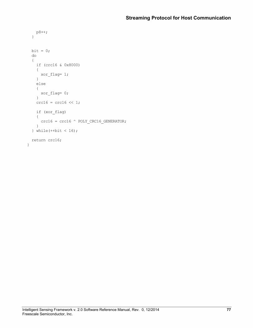
Streaming Protocol for Host Communication
p8++; } bit = 0; do { if (crc16 & 0x8000) { xor_flag= 1; } else { xor_flag= 0; } crc16 = crc16 << 1; if (xor_flag) { crc16 = crc16 ^ POLY_CRC16_GENERATOR; } } while(++bit < 16); return crc16; }
Intelligent Sensing Framework v. 2.0 Software Reference Manual, Rev. 0, 12/2014 77 Freescale Semiconductor, Inc.

How to Reach Us: Home Page: freescale.com Web Support: freescale.com/support
Information in this document is provided solely to enable system and software implementers to use Freescale products. There are no express or implied copyright licenses granted hereunder to design or fabricate any integrated circuits based on the information in this document. Freescale reserves the right to make changes without further notice to any products herein.
Freescale makes no warranty, representation, or guarantee regarding the suitability of its products for any particular purpose, nor does Freescale assume any liability arising out of the application or use of any product or circuit, and specifically disclaims any and all liability, including without limitation consequential or incidental damages. “Typical” parameters that may be provided in Freescale data sheets and/or specifications can and do vary in different applications, and actual performance may vary over time. All operating parameters, including “typicals,” must be validated for each customer application by customer’s technical experts. Freescale does not convey any license under its patent rights nor the rights of others. Freescale sells products pursuant to standard terms and conditions of sale, which can be found at the following address: freescale.com/SalesTermsandConditions.
Freescale and the Freescale logo are trademarks of Freescale Semiconductor, Inc., Reg. U.S. Pat. & Tm. Off. All other product or service names are the property of their respective owners.
© 2014 Freescale Semiconductor, Inc.
Document Number: ISF2P0_KINETIS_SW_REFERENCE_RM Revision 0, 12/2014