
Intelligent Pendulum - Munro...
21
1 MUNRO INSTRUMENTS Intelligent Pendulum Instrucons Manual Munro Instruments Ltd Gilbert House 406 Roding Lane South Woodford Green Essex, IG8 8EY Tel: +44 (0) 20 8551 7000 Email: [email protected] Website: www.munroinstruments.com
Transcript of Intelligent Pendulum - Munro...

1
MUNRO I N S T R U M E N T S
Intelligent PendulumInstructions Manual
Munro Instruments LtdGilbert House
406 Roding Lane SouthWoodford Green Essex, IG8 8EY
Tel: +44 (0) 20 8551 7000Email: [email protected]
Website: www.munroinstruments.com

2
Contents1.0 Introduction 3 1.1 Equipment List 3
2.0 Installing the Software 4
3.0 Interface Box 4 3.1 Power Source 5 3.2 Recharging the Interface Box 5
4.0 Pairing via Bluetooth 6
5.0 Using the Interface Box 6 5.1 Introduction 6 5.1.1 Menu Navigation 7 5.2 New User or Experienced User 7 5.3 Setup Procedure (Menu Section 1) 7 5.4 Setting the Zero (Menu Section 2) 7 5.4.1 The Zero Has Not Been Set 8 5.4.1.1 The Pointer Reads ZERO 8 5.4.1.2 The Spindle Does Not Read ZERO 8 5.4.2 The Zero Has Already Been Set On-site 9 5.4.3 The Pointer Reads Zero, but the Digital Value Does Not Match 9 5.4.3.1 Re-tightening Sensor Housing 9 5.4.3.2 Setting the Datum 9 5.5 Preparing the Sliders (Menu Section 3) 10 5.6 Slider Verification (Menu Section 4) 11 5.6.1 General Information 11 5.6.2 Verification Test for Slider 55, CEN or Slider 96? 11 5.6.3 Verification of Slider 55 and CEN 12 5.6.4 Verification Procedure for Slider 96 13 5.7 Perform a Test (Menu Section 5) 14 5.7.1 Using the Interface Box When Performing a Test (instructions not required) 14 5.7.2 Using the Interface Box when Performing a Test (instructions required) 14 5.8 Free-Style Testing (Menu Section 6) 15 5.9 Setting the Datum (Menu Section 7) 15
6.0 Software 16 6.1 Initial Set up Page 16 6.2 Dashboard 17 6.3 Start a Test Page 17 6.4 Performing a Test 18 6.5 Reports 19 6.5.1 Search Function 20 6.6 Help 20 6.7 Exit 20

3
1.0 IntroductionThe Intelligent Pendulum represents a major advance in the field of slip resistance. Building on the trusted mechanical design of the British Pendulum Tester, this instrument incorporates a number of additional features, enhancing its performance in all aspects of measurement, data capture and reporting.
The Intelligent Pendulum includes a passive sensor which digitally records the Pendulum Test Value (PTV). This is displayed on an OLED read-out, eliminating the possibility of parallax error arising from human uncertainty.
Data is stored and wirelessly exported to specialised slip-resistance software, where a valid and protected test report is automatically generated. Reports are stored indefinitely and can be reopened at a later date for interpretation or recall (as a pdf or csv file).
By streamlining and fortifying the test process (in both operation and reporting), the Intelligent Pendulum can be relied upon to provide quick, accurate and reliable surface measurements, helping users to reduce the incidence of slips and trips.
1.1 Equipment ListAs standard, the Intelligent Pendulum comes with the following equipment:
1. Five Rubber Sliders (TRL(55), 4S(96) or CEN, or a combination of each)2. Conditioning and Verification Surfaces 3. Aluminium Sample Holder4. Perspex Setting Gauge 5. Tools Kit6. Thermometer7. Water Bottle8. Interface Box with OLED Digital Display9. Power Supply Adaptor10. Battery Charger
4
2.0 Installing the SoftwareDownload the software from one of the following links:
• software.munroinstruments.com (unbranded software)• software.munroinstruments.com/[yourcompanyname] (branded software)
It may be necessary to disable your virus checker temporarily to initiate the download.
Please note: The software will only operate on Windows 7, 8 and above.
3.0 Interface Box3.1 Power SourceThe Interface Box can be powered by mains supply (recommended if available) or internal re-chargeable batteries.
The Interface Box will automatically start when a DC mains input is provided or when the menu button is pressed for more than 3 seconds.
If you remove the DC power jack, the Interface Box will switch to battery power.
Once testing is complete, go to Menu Section 9 to turn the Interface Box off. Failure to do so will cause the batteries to drain.
It is recommended that you recharge the batteries after every use.
The DC input for the Interface Box is 7.2V, 600mA.
Once power is available, the screen will display ‘Munro Instruments Intelligent Pendulum’. You can now pair the device to your computer.
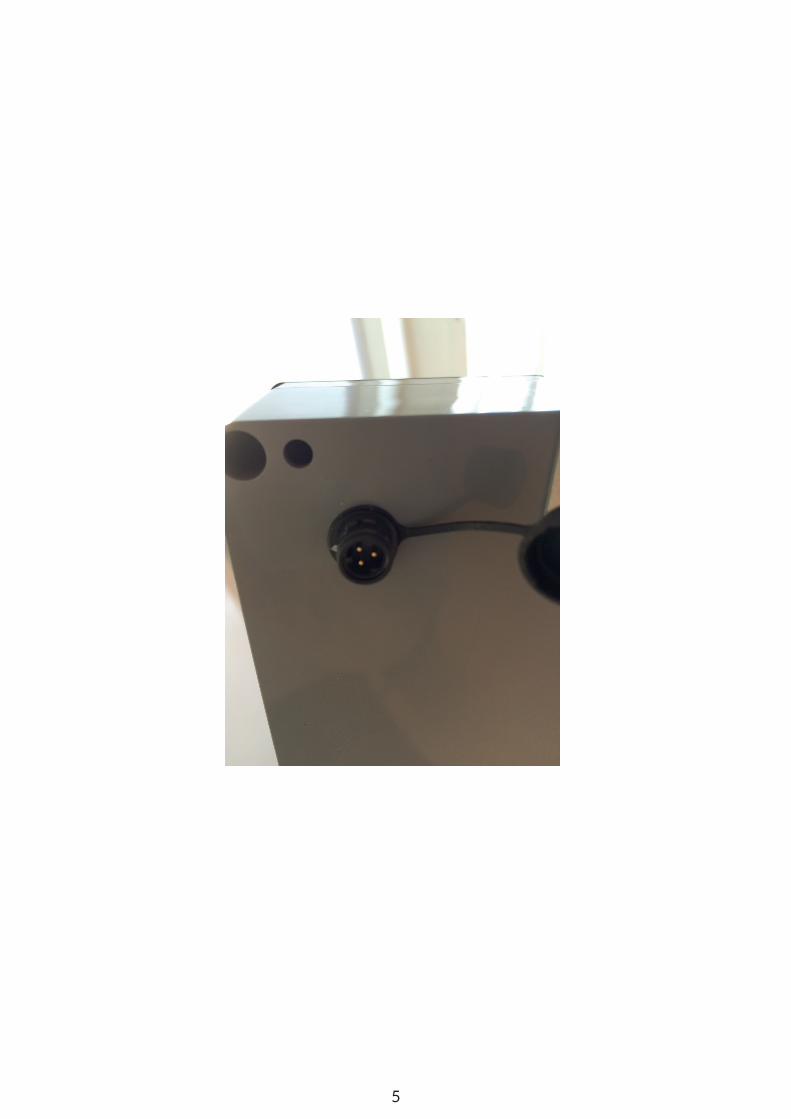
3.2 Recharging the Interface BoxThe charger can fully recharge the batteries in 3 hours. It will automatically end the charge cycle after 6 hours. Use the jack provided on the back of the Interface Box for charging (DC input). The charger and DC input use a 3-pin connector, as shown in the figure on the opposite page.
Warning: Do not charge the Interface Box whilst it is still in use. This will reduce battery life and may cause an electrical fire.
5
6
The Intelligent Pendulum uses a Bluetooth connection to wirelessly export test data from the instrument to the software:
Please follow the instructions given below to ensure correct connection:
1. Once the Interface Box has been turned on, the Intelligent Pendulum will be discoverable.
2. On the computer, click on the Bluetooth icon and ‘Show Bluetooth devices’.
3. The Intelligent Pendulum is discoverable under the name ‘MUNRO-SKID’. Double click on the device to begin the synchronisation process.
4. The Intelligent Pendulum will ask you to type in a password to complete the mating process. The password is 1234. Alternatively, if you asked for a mating code click ‘Yes’ and ‘Next’.
5. Once the password has been verified, the laptop and the Intelligent Pendulum will be paired.
Please note: Always go through the pairing process with the Bluetooth sensor, even if you have paired with the device in the past. Do not assume it will automatically pair when in range.
4.0 Pairing via Bluetooth
5.0 Using the Interface Box5.1 IntroductionThe Interface Box is an interactive system that provides onsite, real-time information. It also acts as a communication gateway between the Pendulum and the software.
The following chapters will guide the user through the testing process:
1. Setup Procedure: How to assemble and set up the Intelligent Pendulum.
2. Setting the Zero: Setting the zero and calibrating the sensor.
Please Note: You cannot test using the Intelligent Pendulum unless you have correctly ‘zeroed’ the pointer and calibrated the sensor. Please complete this before any other test stage.
3. Slider Preparation: How to prepare new and already-used rubber sliders.
4. Verification Procedure: Verifying test results
Please Note: Testing cannot begin until the system has been correctly verified and the verifica-tion data exported to the software.
5. Perform a Test: How to export test results to the software.
6. Free-Style Testing: Free-style testing should be used for diagnostic purposes to check point-er-sensor calibration is correct.

7
Please Note: Do not use this setting for zeroing, preparation, verification or testing. This data will not be exported. It is to be used purely as a diagnostic tool.
7. Setting the Datum: In the event that the sensor housing has been moved during transit or testing, the sensor can be manually adjusted to ensure that it fits within the calibration limits.
8. Engineers mode: Please contact [email protected].
9. Power off: To switch the Interface Box off when it is using battery power.
5.1.1 Menu NavigationTo cycle through the menu options, press the MENU button.
To select an option, press YES or NO (refer to section 5.2 for user modes).
Press MENU to return to the main menu.
Section 1: Setup ProcedureSection 2: Setting the Zero Section 3: Prepare the SlidersSection 4: Verification Section 5: Perform a TestSection 6: Free-style Testing Section 7: Setting the Datum Section 8: Engineers Mode Section 9: Turn Off
5.2 New User or Experienced User The Interface Box provides instructions for new users of the British Pendulum (and the Intelligent Pendulum). When asked ‘Do you require instructions?’, pressing NO will either bypass the instruc-tions entirely or ask important summarised questions.
5.3 Setup Procedure (Menu Section 1)
This section gives prompts for correctly assembling the instrument. Please refer to the Portable Skid Resistance Tester manual for more information.
5.4 Setting the Zero (Menu Section 2)
This is a MANDATORY section. It must be completed before testing can be commence.
The Intelligent Pendulum uses a passive sensor to read the location of the pointer on the scale plate. Setting the zero is vital before testing. The sensor must be calibrated to the zero each time

8
the Pendulum is disassembled and re-assembled or when testing at a new site.
The Box will ask ‘Has the Zero Been Set?’. Answer YES or NO accordingly.
5.4.1 The Zero Has Not Been Set
1. When asked ‘Has the Zero Been Set?’, press NO.
2. The interface box will instruct the user how to set the zero. Make sure the pendulum arm clears the surface. Lock it in position and then press YES.
3. The sensor’s datum is when the pendulum arm is locked into the release mechanism. Ensure the pendulum arm is locked securely in the mechanism before continuing.
4. Rotate the pointer anti-clockwise until the counter-balance rests on the nylon stopper and is parallel with the pendulum arm.
5. When ready, release the pendulum arm so that it swings freely. Catch the pendulum arm as it returns downwards. Place the pendulum arm back in the release mechanism.
6. Does the pointer read zero?
5.4.1.1 The Pointer Reads ZERO 1. When asked ‘Does the Pointer Read Zero?’, press YES. This will calibrate the sensor. The
pointer must hit zero 3 times before the sensor is correctly calibrated.
2. Release the pendulum arm and check the PTV. Does it read zero?
3. If the pointer reads zero (0), place the pendulum arm into the lock mechanism and repeat the process 3 times for verification purposes.
4. Once complete, the system will accept the calibration.
5.4.1.2 The Pointer Does Not Read ZEROIf the pointer does not read zero, the friction rings need to be adjusted.
If the pointer goes off the scale (above zero), then the friction rings need to be tightened by mov-ing them very slightly in a clockwise direction.
If the pointer is below zero on the scale plate, then the friction rings need to be loosened to reduce friction on the spindle. Move the friction rings very slightly in an anti-clockwise direction.
Once the friction rings have been adjusted, release the pendulum arm to allow the pointer to reach its position .
Does the pointer read zero? If yes, press YES and return the pendulum arm to the locking mech-

9
anism. Return the pointer to the nylon stopper and repeat the process 3 times. Once complete, the system will accept the calibration figure for the sensor.
If the pointer does not read zero, please refer to section 5.4.1.2 and repeat the process.
5.4.2 The Zero Has Already Been Set On-siteIf you move to a new test location, the instrument must be ‘zeroed’ prior to use. This ensures accurate, reliable and repeatable results. If you have already ‘zeroed’ the pendulum tester as per the instructions above, please proceed:
1. When asked ‘Setting the Zero. Has the Zero Been Set?’ press YES. The Interface Box will then give you a number of prompts.
2. Lock the pendulum arm into the mechanism and move the pointer to the nylon stopper so that it is in a horizontal position.
3. Release the pendulum arm. As you have already set the zero, the PTV value should also be zero. If this is the case, repeat 3 times to ensure the sensor is correctly calibrated.
If the pointer does not read zero, please refer to section 5.4.1.2 and repeat the process.
5.4.3 The Pointer Reads Zero, but the Digital Value Does Not MatchIn rare cases, the zero has been set, but the digital value will give a reading that does not match. This may indicate that the sensor housing has come loose during transit, causing the sensor to ‘de-calibrate’. Please follow the instructions given below to realign the sensor.
5.4.3.1 Re-tightening Sensor Cover The sensor cover should be securely fastened to the bearing hub of the Intelligent Pendulum by rotating fully on the thread. 3 grub screws are used to lock the cover into place and prevent rota-tion. If the sensor is out of position, re-tighten the sensor cover to its maximum torque limit.
5.4.3.2 Setting the Datum You will need to check that the datum is now within its correct limits for zero calibration.
1. Exit the section ‘Setting to Zero’ by pressing MENU. Press MENU five times to reach Section 7: ‘Set Datum’. Press YES.
2. The Interface Box will prompt you to lock the pendulum arm into place. Press YES.
3. You will be asked to remove the sensor cover from the sensor housing. The sensor cover is located on the front of the sensor housing and is designed to protect the sensor from dam-

10
age. Unscrew it to expose the sensor adjustment screw, as shown in the figure below. Press YES on the Interface box.
4. The Interface Box will enter into real-time display of the sensor. When in a fixed position, the sensor must have a real-time figure between 3050 and 3100.
5. To increase the value of the sensor, turn the adjustment screw anti-clockwise using a flat headed screwdriver. To reduce the value of the sensor reading, turn the adjustment screw clockwise.
6. The value can be any value between 3050-3100. The factory setting is 3075.
7. Once you have adjusted the sensor and it is within the range, press YES. This will save and update the new sensor datum point. Re-mount the sensor housing cover.
Please go to section 5.4.1 and follow the zeroing instructions.
5.5 Preparing the Sliders (Menu Section 3)The Interface Box will provide prompts for rubber slider preparation.
If you are an experienced user, you may bypass this section.
If you require instructions, press YES. The Interface Box will first ask you the type of slider being used? Press YES for slider 55 or CEN and NO for slider 96.
This section will guide you through the slider preparation procedure. The Interface Box will record the number of swings performed during the preparation procedure.
Please Note: It is the user’s responsibility to ensure that the rubber slider is conditioned and verified correctly according to UKSRG and BSI guidelines. The Interface Box is there as a guide only. Munro Instruments accepts no liability if conditioning and verification of sliders or testing is carried out incorrectly.

11
5.6 Slider Verification (Menu Section 4) Slider verification is critical for ensuring that the Intelligent Pendulum is in working order. By veri-fying the machine, users can be confident that results are accurate and repeatable. Verification is achieved by testing a number of well-defined surfaces with established PTV values. If, on testing these surfaces, the results fall within a certain limit, the Pendulum is verified and ready for use.
5.6.1 General InformationThe verification results will be exported to the Perform a Test page on the software. You will need to perform the verification procedure at every new test location or every 24 hours. Once you have successfully completed the verification procedure, you will be asked if you wish to perform a new test. You can automatically export the verification results into your new test report if the location is the same.
5.6.2 Verification Test for Slider 55, CEN or Slider 96?The Interface Box will provide instructions if required.
Slider 55, CEN and slider 96 have similar but not identical verification procedures. It is important that the user selects the correct verification process. The test surfaces are prepared in different ways and will thus give different results.
Please Note: Please keep verification surfaces for slider 55 separate from slider 96 verification surfaces. For more information on the slider surfaces, please refer to the traditional user guide for the Portable Skid Resistance Tester.
As a quick guide, the two verification processes are summarised below:
Table 1: Verification Values for Slider 55
Table 2: Verification Values for Slider 96
Verification Surface PTV
1 Pink Lapping Film (Wet) 59 -64
2 Float Glass (Wet) 5 - 10
3 Pavigres Tile (Wet) 32 - 36
Verification Surface PTV
1 Float Glass (Wet) 5 - 10
2 Pavigres Tile (Wet) 13 - 19

12
Notice that there are only two verification surfaces for the slider 55, whereas the slider 96 re-quires three to be tested. All need to be within range before formal testing can commence.
Please Note: There are no established verification surfaces for the CEN rubber slider. As its hardness is similar to that of the slider 55, it is advised that the same verification surfaces are used. However, this is at the user’s discretion. The user should keep abreast of any develop-ments in slip-resistance guidelines.
5.6.3 Verification of Slider 55 and CEN1. The menu screen will ask if you would like instructions. Press YES.
2. Pressing YES again will bypass the verification procedure. If this is a new test site, press NO. This will take you to the next screen. Press YES for Slider 55.
3. The Interface Box will guide you through setting the footprint and locking the pendulum arm and spindle in position. Pressing YES will move you through the steps.
4. You will now need to perform 8 swings over the wet float glass. With each pendulum swing, the sensor will detect the PTV value and display it on the Interface Box. This value will be stored on the Box.
Please Note: The digital value may be ±1 of what you see on the PTV scale. This resolution has been tested and agreed with the UK Health and Safety Laboratory and is in accordance with the resolution specified with the UKSRG.
5. After the swing, return the pendulum arm to its locked position. Spray water over the tile and release to retest. Repeat this process 8 times to complete the test sequence. After 8 tests, the Interface Box will present the 8 recorded values and the median. These values will be exported wirelessly to the test report and locked.
6. The Interface Box will ask if the recorded values were within the verification range (5-10 for float glass). Press YES or NO as appropriate. YES will allow you to move on to the next veri-fication surface; NO will bring you back to the verification menu. Repeat the tests as neces-sary.
7. Replace the float glass with the Pavigres Tile and reset the footprint of the slider onto the Pavigres Tile.
Please Note: The Pavigres Tile must be specially conditioned according to the type of slider being used.
8. Perform 8 swings on the Pavigres Tile as per steps 4 - 5. At the end of the testing, the values will be summarised. The Interface Box will ask if the values are in range. If in range, press YES and the data will be exported wirelessly to the Perform a Test page. The Interface Box will confirm that the tester had now been verified. You can now proceed to section 5.7.
5.6.4 Verification Procedure for Slider 961. The menu screen will ask if you would like instructions. Press YES.
2. Pressing YES again will bypass the verification procedure and move you on to the next sec-

13
tion. If this is a new test site, press NO. This will take you to the next screen. Press NO for Slider 55. Press YES for Slider 96.
3. The Interface Box will give the user a series of prompts. Press YES after completing each action. First, add the float glass to the sample holder and then secure the Pink Lapping Film OVER the float glass. Spray the pink lapping film with water. Set the footprint for the slider and then lock the pendulum arm into the locking mechanism and bring the pointer counter-weight round to the nylon stopper.
4. Perform 8 swings of the pendulum tester, ensuring that you spray water onto the pink lap-ping film after every swing.
5. The data will be recorded and wirelessly exported to the Perform a Test page. The Interface Box will present the test results and will ask you whether the median is in the correct range. If it is in range, press YES. Press NO if the data is not in the range. This will take you back to the main menu, where you will need to troubleshoot the issue.
6. If the test results are in range, move on to the float glass. Remove the pink lapping film to expose the float glass. Reset the footprint and carry out another 8 swings, ensuring that you spray water onto the float glass after every swing.
7. Again, the data will be exported wirelessly to the software. The test results will also be shown on the Interface Box. Check whether the data is within the required range required. Press either YES or NO dependent on whether the data falls within the range.
8. Remove the float glass from the sample holder and replace with the Pavigres Tile. Set the footprint and wet the tile.
Please Note: The Pavigres Tile must be specially conditioned according to the type of slider being used.
9. Perform 8 swings, ensuring that you spray water onto the tile after each swing.
10. The results will be shown on the Interface Box and wirelessly exported to the software. If the median falls within the specified range, press YES. Verification is now complete, and the user can now proceed with testing. If the slider falls out of range, press NO and troubleshoot any problems.
Once you have verified the slider, proceed to section 5.7 Perform a Test.
5.7 Perform a Test (Menu Section 5)The Perform a Test section will allow you to formally test a site and create a valid and locked test report. This is accessible only after having verified the instrument. The Interface Box and software work together to allow you create your test report. For details of the software please see section 6.

14
5.7.1 Using the Interface Box When Performing a Test (in-structions not required)The front menu will ask if you need instructions. If you are an experienced user, you can bypass the instructions by pressing NO. This will take you straight into testing mode. The Interface Box will ask the user to return the pendulum arm to the locking mechanism and move the pointer to the nylon stopper. Press YES to confirm these actions have been completed.
Perform 8 swings. The median of the final five swings will be calculated. Once complete, the data will be exported wirelessly to the Perform a Test page on the software. The Interface Box will then ask ‘Would you like to perform another test?’. Pressing NO will take the user back to menu section 1 (Setup Procedure).
The tests will be given a test ID. It is the user’s responsibility to add details of the test conditions. For further details please refer to section 6.3.
5.7.2 Using the Interface Box when Performing a Test (in-structions required)The Interface Box will ask if you require instructions. Pressing YES will take you through a series of prompts.
1. The Interface Box will ask whether the surface is being tested ‘as found’ or whether it has been cleaned, treated or adjusted in some way. If YES, the Interface Box will prompt the user to set the slider footprint. It will then ask whether the test surface is in a wet or dry condi-tion. Press YES or NO accordingly. The Interface Box will then wait until the pendulum arm is locked into position and the pointer counter-weight is resting against the nylon stopper.
2. Perform 8 swings. The median of the final five swings will be calculated. Once complete, the data will be exported wirelessly to the Perform a Test page on the software. The Interface Box will then ask ‘Would you like to perform another test?’. Pressing NO will take the user back to menu section 1 (Setup Procedure).
3. If the surface has been tested ‘as found’, the first 3 values will be of critical importance. These values will represent the condition of the floor under these conditions.
4. The data will be exported onto the software and stored in a table.
Please Note: It is the user’s responsibility to add the floor/location description onto the test report.
5. If the user is not testing a surface ‘as found’ (i.e. it has been altered or treated in some way), press NO. The Interface Box will prompt you to clean and dry the slider before setting the footprint.
6. The Interface Box will then ask if the surface is wet or dry. Press YES or NO accordingly. The Interface Box is then ready for data collection. The pendulum arm should be locked into place and the pointer counter-weight placed against the stopper.
7. Perform 8 swings. In this instance, the median of the final five swings will be of greatest im-portance.
15
Please Note: It is the user’s responsibility to add the floor/location description onto the test report.
5.8 Free-Style Testing (Menu Section 6)Free-style testing is used for diagnostic purposes only. No data will be exported to the test report, and there is no check for validation.
Free-style style testing is also used to check whether the sensor is measuring correctly after changes have been made to the instrument during diagnostics or troubleshooting.
During testing, the PTV will be shown on the screen, but the data will not be exported.
5.9 Setting the Datum (Menu Section 7) In the unlikely event that there is an issue with the sensor, this will allow users to make small adjustments to the alignment of the sensor. In some cases, the sensor may have been rotated or knocked during transit. This section will allow the user to a) see if the sensor has been moved b) re-set the datum.
1. After pressing YES on the menu, the Interface Box will ask you to remove the sensor housing cover. This will expose the sensor.
Please Note: A small flathead screwdriver and a larger flathead screwdriver are recommended for sensor-cover removal and sensor adjustment.
2. Removing the cover will expose the sensor adjustment screw. A larger flathead screwdriver is required.
3. Lock the pendulum arm into the locking mechanism. This is the datum position for the sen-sor.
4. The sensor must have a reading between 3050-3100 for the measurement process to be ac-curate. If the sensor falls out of range, the digitally-recorded PTV will be inaccurate.
5. The Interface Box will show the sensor range (3050-3100) and will also give the current value of the sensor in its datum position.
6. The sensor can be ANY NUMBER in this range. The factory setting is 3075.
7. Using a flathead screwdriver, carefully move the sensor anti-clockwise to increase the sensor value and clockwise to reduce the sensor value. The sensor value will change in real-time to prevent over-/under-adjustment.
8. Once the sensor is in the correct range, press YES on the Interface Box. This will save the new sensor value.
9. Carefully remount the sensor cover. Make sure you do not knock it, as this will take it out of range.
The sensor can now be ‘zeroed’.

16
6.0 Software Please Note: Ensure that you have paired the Intelligent Pendulum and computer via Bluetooth before using the software. Failure to do so will result in no data transfer. If you have not paired the devices, please refer to Section 4.0 to pair the devices.
It is assumed that you are familiar with the functionality and operation of the Intelligent Pendulum Interface Box detailed in Section 5.0. If in doubt, please contact our technical support team ([email protected]).
6.1 Initial Set up Page Opening the software will take you to the Initial Setup page. See below:
1. Fill in the Engineer Details.
2. Click Refresh. The screen will now show all discoverable Bluetooth devices. As you have al-ready paired the Intelligent Pendulum (shown in figure 6 as bt-skid) this will show up on this list. Select the device and then click Pair.
3. Enter the Intelligent Pendulum serial number.
4. Click save.
6.2 Dashboard The Dashboard contains a summary of engineer and device details. See Figure 7.

17
6.3 Start a Test PageThe Start a Test page contains details of the current test. The test report conforms to guidelines set by the UK Slip Resistance Group.
A test report contains the following information:
1. Job Number2. Location/Sample Designation3. Date and Operator4. Room Temperature5. Rz Surface Micro Roughness Readings6. Pendulum Serial Number 7. Calibration Due Date 8. Type of Slider Rubber used 9. Batch Number of Slider Used 10. Slider Preparation Process 11. Has the Tester been Levelled and Zeroed? 12. Verification readings 13. Floor description and condition 14. Test results table

18
6.4 Performing a Test 1. Before testing, click Start a Test on the side Menu. This will open up a new Test Report. If a
test has not been performed in the last 24 hours, a notice will appear informing you whether or not the verification procedure is necessary.
2. Fill in the job number and job location.
3. The date is added automatically but can be manually adjusted if necessary.
4. The User field will be filled in automatically but can be manually adjusted if necessary.
5. The Temperature field should be filled in manually.
6. Rz microroughness readings can be filled in at user discretion.
7. The Pendulum serial number will be appear automatically but can be changed at the user’s discretion.
8. The Calibration Due Date will need to be filled in by the user.
9. Ensure the Intelligent Pendulum is correctly assembled.
10. The Intelligent Pendulum should be levelled and zeroed. Once this is done, mark the corre-sponding field on the Test Report.
11. Indicate on the report which type of slider is being used.
12. Verification of the sliders is critical. On the Interface Box, select the type of slider that will be used. During the verification procedure, data will automatically be sent to the Test Report. This data will appear in the verification table. There should be no need to change the test surface name. Data will be locked so that it cannot be accidently deleted.
19
Depending on the type of slider used, different verification surfaces must be used. To complete the verification procedure, the Pendulum must give readings within a specific range. The correct test ranges have been programmed into the Interface Box.
If the slider falls out of range, you will need to troubleshoot the problem and start the verification process again. If this is the case, the original results will be kept. The new verification results will be shown in the same table.
13. Once verification has been completed, testing can commence.
14. If the test surface is on a slope, the user can add the elevation onto the test report.
15. Test the surface by following the instructions on the Interface Box. The test data will be locked to prevent accidental deletion.
16. It is the user’s responsibility to fill in the descriptive fields on the report. The user can under-take as many tests as required. The table will update automatically.
17. Once testing has finished, click Save.
18. When conducting a new test, the data obtained from the original verification process will be automatically inputted into the new test report. Use this feature only if you are using the same slider as the previous test. If you switch from a slider 55 to a slider 96, you will need to verify the Pendulum again using the slider 96.
6.5 ReportsSaved reports can be accessed by clicking on the Reports tab. See figure 9 below.
The table will show the job number, location, slider batch number and the date of test.
At the bottom of the table there will be two options:
1. Export pdf 2. Export csv
If you select either Export pdf or Export csv without selecting a particular test, the entire list of will be exported.
To select a test report, a single click will highlight the row on the table. Reports can be reopened and edited if required. This will allow the user to fill in any additional information that they may have been missed on-site. Once the details have been modified, re-save the report.

20
6.5.1 Search Function The search function allows users to find specific reports based on certain search criteria. The search function is on the top right-hand-side of the page.
The search criteria are as follows:
• Job number• Location• Date of experiment
Entering one or more of these search terms and then pressing search will bring up the relevant reports.
Please Note: Pressing enter will not activate the search. Press search manually. Pressing clear will bring all test report files back onto the table.
6.6 Help The help section will bring up useful contact details and will also provide a link to an electronic copy of this user manual.
6.7 Exit You can exit the software by pressing Exit on the side panel and then exit on the screen.

21
Munro Instruments LtdGilbert House
406 Roding Lane SouthWoodford Green Essex, IG8 8EY
Tel: +44 (0) 20 8551 7000Email: [email protected]
Website: www.munroinstruments.com
MUNRO I N S T R U M E N T S