
Intelligent alarms in anesthesia : a real time expert ... · Intelligent alarms in anesthesia: a...
178
Intelligent alarms in anesthesia : a real time expert system application Aa, van der, J.L.C.M. DOI: 10.6100/IR330395 Published: 01/01/1990 Document Version Publisher’s PDF, also known as Version of Record (includes final page, issue and volume numbers) Please check the document version of this publication: • A submitted manuscript is the author's version of the article upon submission and before peer-review. There can be important differences between the submitted version and the official published version of record. People interested in the research are advised to contact the author for the final version of the publication, or visit the DOI to the publisher's website. • The final author version and the galley proof are versions of the publication after peer review. • The final published version features the final layout of the paper including the volume, issue and page numbers. Link to publication General rights Copyright and moral rights for the publications made accessible in the public portal are retained by the authors and/or other copyright owners and it is a condition of accessing publications that users recognise and abide by the legal requirements associated with these rights. • Users may download and print one copy of any publication from the public portal for the purpose of private study or research. • You may not further distribute the material or use it for any profit-making activity or commercial gain • You may freely distribute the URL identifying the publication in the public portal ? Take down policy If you believe that this document breaches copyright please contact us providing details, and we will remove access to the work immediately and investigate your claim. Download date: 20. Aug. 2018
Transcript of Intelligent alarms in anesthesia : a real time expert ... · Intelligent alarms in anesthesia: a...

Intelligent alarms in anesthesia : a real time expertsystem applicationAa, van der, J.L.C.M.
DOI:10.6100/IR330395
Published: 01/01/1990
Document VersionPublisher’s PDF, also known as Version of Record (includes final page, issue and volume numbers)
Please check the document version of this publication:
• A submitted manuscript is the author's version of the article upon submission and before peer-review. There can be important differencesbetween the submitted version and the official published version of record. People interested in the research are advised to contact theauthor for the final version of the publication, or visit the DOI to the publisher's website.• The final author version and the galley proof are versions of the publication after peer review.• The final published version features the final layout of the paper including the volume, issue and page numbers.
Link to publication
General rightsCopyright and moral rights for the publications made accessible in the public portal are retained by the authors and/or other copyright ownersand it is a condition of accessing publications that users recognise and abide by the legal requirements associated with these rights.
• Users may download and print one copy of any publication from the public portal for the purpose of private study or research. • You may not further distribute the material or use it for any profit-making activity or commercial gain • You may freely distribute the URL identifying the publication in the public portal ?
Take down policyIf you believe that this document breaches copyright please contact us providing details, and we will remove access to the work immediatelyand investigate your claim.
Download date: 20. Aug. 2018

INTELLIGENT AlARMS IN ANESTHESIAa real time expert system application

CIP-GEGEVENS KONINKLIJKE BIBLIOTHEEK, DEN HAAG
Aa, Johannes Jacobus Leonardus Catherina Maria van der
Intelligent alarms in anesthesia: a real time expert system application / Johannes JacobusLeonardus Catherina Maria van der Aa. - [S.l. : s.n.]. - Fig., tab.Proefschrift Eindhoven. - Met lit. opg., reg.ISBN 90-9003303-3SISO 608.1 UDC 616-089.5(043.3) NUGI 742Trefw: anesthesie; patientbewaking / expertsystemen
INTELLIGENT ALARMS IN ANESTHESIAa real time expert system application
PROEFSCHRIFf
ter verkrijging van de graad van doctor aan deTechnische Universiteit Eindhoven, op gezag van
de Rector Magnificus, prof. ir. M. Tels, vooreen commissie aangewezen door het College van
Dekanen in het openbaar te verdedigen opvrijdag 11 mei 1990 te 16.00 uur
door
Johannes Jacobus Leonardus Catherina Maria van der Aa
geboren te Aarle-Rixtel (NB)

Dit proefschrift is goedgekeurd door de promotoren:
Prof. dr. ir. Jan E. W. BenekenenProf. Joachim S. Gravenstein M.D., Dr. h.c.(Dniversity of Florida)

The work reported in this dissertation on the "Intelligent Alarms Project" is the result ofa collaboration between the Department of Anesthesiology at the University of Florida(Chairman: Prof. Jerome H. Modell M.D.) in Gainesville, Florida and the Division ofMedical Electrical Engineering (Chairman: Prof. dr. Jan E. W. Beneken) from theEindhoven University of Technology in Eindhoven, the Netherlands.The project was supported in part by Ohmeda, a division of The BOC Group Inc.

''And at night you will look up at the stars. Where I liveeverything is so small that I cannot show you where my star isto be found. It is better like that. My star will be just one ofthe stars for you. And so you will love to watch all the starsin the heavellS...."
Antoine de Saint ExuperyThe Little Prince
In memory of Ans

ACKNOWLEDGEMENTS
The research described in this dissertation is the result of an intense collaboration
with numerous persons having made significant contributions.
Professor Beneken, your guidance, support, in depth discussions, suggestions, and
the many constructive remarks during your many visits to our Gainesville crew made it
all possible. For many wonderful years, thank you.
Professor Gravenstein, ten years ago you offered me the opportunity to come to
Gainesville and work in your group. Thank you for that opportunity. In these ten years
you have taught me so many invaluable things; you supported, encouraged, and guided
me to where I am today. Without you, this research and many other projects would not
have been possible. Moreover, as domain expert, your input was essential.
Additional clinical knowledge was provided by a great team of enthusiastic
anesthesiologists: Drs. Jeff Feldman, Gordon Gibby, Mike Good, Peter Pan, and David
Paulus. Thank you for your help and support.
Hans Blom, you gave the project the SIMPLEXYS toolbox to convert our ideas
into prototypes. Despite the distance between Gainesville and Eindhoven the
collaboration was exemplary.
Many graduate students have worked on the "Intelligent Alarm" project: Bert de
Vries, Rob Bastings, Hans van Oostrom, Jelle Nederstigt, Seong Choi, Chieteuk Abn,
Frank Gomez, and John Noll. Their valuable contributions are acknowledged and very
much appreciated.
My thank goes out to the entire Department of Anesthesiology at the University
of Florida and its chairman Dr. Jerome H. Modell M.D., for their interest, support, help,
and for allowing me to use the laboratory and various other facilities.
Ingrid Mellone, who read and edited early drafts of this dissertation, and Dr. David
Pharies thank you for your editorial assistance and valuable suggestions.
To my wife Ria, for countless reasons, I am indebted.
Acknowledgements

ii
CONTENTS
ACKNO~DGEMENTS
CONTENTS. . . . . . . . . . . . . . . . . . . . . . . . . . . . . . . . . . . . . . . . . . . . .. ii
1. INTRODUCTION 11.1. Background 11.2. Project Objective . . . . . . . . . . . . . . . . . . . . . . . . . . . . . . . . . . ., 51.3. Chapter Outline 5
2. ANESTHESIA ISSUES. . . . . . . . . . . . . . . . . . . . . . . . . . . . . . . . . . . .. 72.1. General Anesthesia .... . . . . . . . . . . . . . . . . . . . . . . . . . . . . .. 72.2. Anesthesia Equipment and Stages during Anesthesia 8
2.2.1. The Endotracheal Tube. . . . . . . . . . . . . . . . . . . . . . . . .. 82.2.2. The Anesthesia Machine ..... . . . . . . . . . . . . . . . . . . ., 92.2.3. The Anesthesia Breathing System 102.2.4. The Anesthesia Ventilator . . . . . . . . . .. 11
2.3. The Circle Breathing Circuit .. . . . . . . . . . . . . . . . . . . . . . . . . .. 13
3. MONITORING DURING ANESTHESIA . . . . . . . . . . . . . . . . . . . . . . . .. 173.1. Why Monitor , 173.2. What to Monitor 193.3. How often to Monitor . . . . . . . . . . . . . . . . . . .. 223.4. How to Monitor . . . . . . . . . . . . . . . . . . . . . . . . . . . . . . . . . . .. 23
3.4.1. Monitoring Oxygenation. . . . . . . . . . . . . . . . . . . . . . . . .. 243.4.2. Monitoring Ventilation 253.4.3. Monitoring Circulation 263.4.4. Monitoring Temperature 273.4.5. Monitoring the Neuromuscular Junction 273.4.6. Vigilance 273.4.7. Preoperative Information . . . . . . . . . . . . . . . . . . . . . . . .. 28
3.5. Signal Processing and Data Presentation 28
4. ALARMS . . . . . . . . . . . . . . . . . . . . . . . . . . . . . . . . . . . . . . . . . . . . .. 314.1. Current Alarm Technology 314.2. Possible Improvements . . . . . . . . . . . . . . . . . . . . . . . . . . . . . . .. 33
4.2.1. Dealing with Artifact 344.2.2. Trend Detection 344.2.3. Multi-Variable Tactics. . . . . . . . . . . . . . . . . . . . . . . . . .. 344.2.4. Integration and Communication . . . . . . . . . . . . . . . . . . . ., 35
Contents

iii
4.3. Toward Intelligent Alarms . . . . . . . . . . . . . . . . . . . . . . . . . . . . .. 354.3.1. Fantasy or Possibility? . . . . . . . . . . . . . . . . . . . . . . . . . .. 364.3.2. The Layered Approach . . . . . . . . . . . . . . . . . . . . . . . . .. 38
4.4. Limits and Alarms " 41
5. IMPLEMENTING INTELLIGENT ALARMS . . . . . . . . . . . . . . .. 425.1. Monitoring for Patient Safety 42
5.1.1. Detecting Potential Problems 425.1.2. The Differential Diagnosis . . . . . . . . . . . . . . . . . . . .. 435.1.3. Implications and Treatment 45
5.2. Selecting the Area of Implementation . . . . . . . . . . . . . . . .. 465.2.1. The Major Cause of Injury 465.2.2. Suggested Improvements 475.2.3. Scope of the Project . . . . . . . . . . . . . . . . . . . . . . . . . . .. 47
5.3. Project Approach 485.3.2. Possible Approaches . . . . . . . . . . . . . . . . . . . . . . . . . . .. 495.3.3. The Expert Systems Approach 50
6. EXPERT SYSTEMS 526.1. Introduction to Expert Systems 53
6.1.1. Expert System Components 536.1.2. Building an Expert System . . . . . . . . . . . . . . . . . . . . . . .. 56
6.2. Expert Systems Applications in Medicine . . . . . . . . . . . . . . . . . . .. 576.3. Finding an Expert System Tool for Intelligent Alarms 586.4. The Expert System Tool: SIMPLEXYS . . . . . . . . . . . . . . . . .. 60
6.4.1. Introduction 606.4.2. Building Applications with SIMPLEXYS . . . . . . . . . . . . . .. 616.4.3. SIMPLEXYS Rules 626.4.4. SIMPLEXYS Programs . . . . . . . . . . . . . . . . . . . . . . . . .. 64
6.5. SIMPLEXYS and the Intelligent Alarm Project Requirements 716.5.1. Real Time Performance 716.5.2. Linkage with Other Software 726.5.3. Temporal Reasoning. . . . . . . . . . . . . . . . . . . . . . . . . . .. 72
7. IMPLEMENTATION: PROTOTYPE I 747.1. Knowledge Acquisition . . . . . . . . . . . . . . . . . . . . . . . . . . . . . . .. 75
7.1.1. Breathing System Problems 757.1.2. Monitoring the Breathing System. . . . . . . . . . . . . . . . . . .. 777.1.3. Summary 79
7.2. From Knowledge to Signals. . . . . . . . . . . . . . . . . . . . . . . . . . . .. 79
Contents

iv
7.3. Implementation . . . . . . . . . . . . . . . . . . . . . . . . . . . . . . . . . . . .. 827.3.1. Data Acquisition and Signal Processing. . . . . . . . . . . . . . .. 837.3.2. From Signals to Signal Features 837.3.3. From Features to Symbolic Data . . . . . . . . . . . . . . . . . . .. 867.3.4. From Features to Rules 877.3.5. From Software to Hardware. . . . . . . . . . . . . . . . . . . . . .. 907.3.6. About Software, Hardware, and Rules 91
7.4. Tests and Evaluation . . . . . . . . . . . . . . . . . . . . . . . . . . . . . . . .. 937.4.1. Simulator Testing . . . . . . . . . . . . . . . . . . . . . . . . . . . . .. 937.4.2. Test Protocol and Results 947.4.3. Tests in the Operating Room . . . . . . . . . . . . . . . . . . . . .. 967.4.4. Conclusions about the First Prototype 98
8. IMPLEMENTATION: PROTOTYPE II , 998.1. Knowledge Acquisition . . . . . . . . . . . . . . . . . . . . . . . . . . . . . . .. 99
8.1.1. Which Features Change 1008.1.2. How to Change the Feature Baseline 101
8.2. Implementation . . . . . . . . . . . . . . . . . . . . . . . . . . . . . . . . . . . . . 1048.2.1. Data Acquisition 1048.2.2. The User Interface . . . . . . . . . . . . . . . . . . . . . . . . . . . . . 1058.2.3. Software Additions 107
8.3. Tests and Evaluation 1088.3.1. Single Malfunctions 1088.3.2. Multiple Malfunctions 1118.3.3. Conclusions about the Second Prototype . . . . . . . . . . . . . . . 113
9. IMPLEMENTATION: PROTOTYPE III 1149.1. Knowledge Acquisition 115
9.1.1. Inadequate Oxygenation 1169.1.2. Hypoventilation 1179.1.3. Ventilation to Perfusion Mismatch 1189.1.4. Diffusion Abnormality 120
9.2. Estimating PetCOZ 1209.3. From Knowledge to Rules 124
9.3.1. Oxygenation 1259.3.2. Ventilation 1259.3.3. Other Causes 126
9.4. Implementation . . . . . . . . . . . . . . . . . . . . . . . . . . . . . . . . . . . . . 1279.4.1. Data Acquisition 1279.4.2. Software Additions . . . . . . . . . . . . . . . . . . . . . . . . . . . . . 1289.4.3. About Software, Hardware, and Rules 129
Contents

v
9.5. Tests and Evaluation . . . . . . . . . . . . . . . . . . . . 1309.5.1. Simulator Tests in the Animal Model 1309.5.2. Conclusions Regarding the Third Prototype . . . . . . . . . . . . . 133
10. DISCUSSION AND CONCLUSIONS . . . . . . . . . . . . . . . . . . . . . . . . . . . 136
SUMMARY 142
SAMENVATTING 146
REFERENCES . . . . . . . . . . . . . . . . . . . . . . . . . . . . . . . . . . . . . . . . . . . . 150
About The Author . . . . . . . . . . . . . . . . . . . . . . . . . . . . . . . . . . . . . . . . . . 165
Contents

1. INTRODUCTION
1.1. Background
Well over 20 million anesthetic procedures are performed in the United States
(US) each year (Newbower 1981, Gravenstein 1989: Personal communication), by
physicians and nurses with specialized training in anesthesiology. At Shands Teaching
Hospital at the University of Florida in Gainesville, Florida, the Department of
Anesthesiology performed 13,743 anesthetic procedures in 1987, 13,666 procedures in
1988. The number of procedures performed in a recently opened outpatient surgical
center, which is associated with Shands Hospital is not incorporated in these figures. For
the two years combined, about 74% of these procedures were general anesthesia, while
26% were regional anesthetic procedures (figure 1.1).
::1 - ---20f------------
15f------------
10
~Tota I-Genera I
1988 1987 Combi ned
Figure 1.1 The number of procedures under general anesthesia compared to thetotal number of procedures.
Chapter 1 Introduction

2
In the US, general anesthesia is induced predominantly with the help of
intravenous techniques followed by nitrous oxide (NzO) and volatile halogenated agents,
often in combination with intra-venously (IV) administered drugs including muscle
relaxants, opiods, and opiates. Apart from causing anesthesia, these drugs depress vital
organ functions and, thus, pose a potential risk to the patient. It is estimated that
between 2,000 and 10,000 anesthesia-related deaths occur in the US each year (Epstein
1978, Cooper 1984). These "patients do not die from too much analgesia or amnesia;
they die from too much anesthetic in the heart, not enough perfusion to the brain, or
not enough oxygen in the blood" (Gravenstein 1987 p:l). The anesthesia pioneers
recognized that the effects of anesthetics on the respiratory and circulatory systems could
have disastrous consequences (Simpson 1848, Sykes 1960). The anesthetics are one
source of potential hazards. The anesthesia machine and system can introduce other
hazards, specially when some hazards are the result of flaws in the equipment design or
of misuse due to inadequate knowledge of the functioning of the equipment (Eger 1964,
Good 1988). Cooper et al. more recently studied anesthesia mishaps systematically and
introduced the term "critical incident" to anesthesia (Cooper 1978). They defined a
critical incident as a mishap that could have led (if not discovered in time) or did lead
to an undesirable outcome, ranging from increased length of hospital stay to temporary,
then permanent disability, to death. Analysis of critical incidents reveals that the majority
of them were preventable and were caused by human error (Cooper 1978, 1980,
Newbower 1981, Cooper 1984, Davies 1984).
It is the aim of patient monitoring, by continuous surveillance, to detect early or
dangerous deterioration, with reliability and accuracy (Stewart 1970). Intuitively,
monitoring patients under anesthesia during surgery and painful diagnostic procedures
with or without the help of mechanical, electrical, or pneumatical devices will, indeed,
improve patient safety through prevention, provided the devices function properly. A
more accurate description of the goals of monitoring is offered by Gravenstein:
Monitoring of patient and equipment function has 2 goals: the titration of drugs, fluids,
Chapter 1 Introduction

3
and ventilator to a desired end point, and to detect all changes that require correction
if the patient is to be spared ill effects (Gravenstein 1979, 1986, 1987, 1989b, 1990). In
response to the need for improved monitoring techniques called for by surgery of
increased complexity and sophistication, new advanced diagnostic procedures that require
anesthesia, and advances in monitoring fechnology, devices that allow the clinician to
monitor patients extensively have become available in recent years. Despite all the
advances however, monitoring is not yet able to provide data to address certain clinical
concerns. For example, with the current technology one is still unable to measure, among
other things, depth of anesthesia, the effect of anesthesia on the brain, the level of
analgesia or amnesia, and oxygen supply to vital organs. Apart from inherent limitations,
monitoring techniques themselves may impose a danger to the patient or will, as some
argue, give the clinician a false sense of security (Hamilton 1988, Moyers 1988, Stoelting
1988, Orkin 1989). Also, the cost of some monitoring modalities can be a concern
(Hamilton 1986, 1988, Plantes 1988). However, studies suggest that a combination of
monitoring devices can, indeed, prevent anesthetic mishap and patient injury (Cooper
1984, Duberman 1984, Cheney 1988, Pierce 1988). The US judicial system corroborates
this assessment as evidenced through a number of well published, and extremely
expensive lawsuits. The implementation of standards in monitoring to enhance safety,
both nationally and internationally, are materializing (ASA 1986, Eichhorn 1986, Block
1988a, Gravenstein 1989: Personal communication).
Even though the majority of mishaps have been well described in case reports and
in the anesthesia literature, tnishaps continue to occur. We suspect that the dismal
man/machine interface of monitoring instrumentation and the lack of built-in intelligence
to help the clinician may contribute to this. But there are other forces at work.
Monitoring requires a sustained high attention level (vigilance) from the observer: the
clinician. A breakdown of vigilance is implicated in a number of anesthetic mishaps
(Cooper 1978, Craig 1981). Monitoring devices should provide for an adequate backup
Chapter 1 Introduction

4
system in case the clinician is too busy performing other tasks or when vigilance is less
than perfect. There is also another aspect to consider. From the ever increasing number
of monitors used during clinical practice a new pitfall has emerged, information overload.
Simply put, information overload exists when the clinician cannot keep up with all the
data bombarding him from the monitors. Here we tum to alarms for help.
In anesthesia, as in other fields, an alarm is a warning of an approaching or
existing danger. The concept of alarms is simple, attractive, and sound. Merely set a
limit around a variable, and when these alarm limits are exceeded, an auditory and/or
visual alarm sounds. However, the clinical reality is that current alarms often annoy
rather than help the clinician as is evident from the frequency with which alarms are
disabled and ignored by clinicians. For an alarm to be effective, a basic requirement that
the monitoring device provides correct and accurate data must first be satisfied. Too
often, alarms sound when there is no danger to the patient because of artifact or
inappropriate alarm limits. Other difficulties include the non-specificity of the alarm and,
with the proliferation of monitors in the operating room, the large number of possible
alarms. In an average modem operating room, as many as 30 different alarms may go
off when (in many instances inappropriate) alarm limits are exceeded. With the increase
in the use of alarms, the excessive number of alarm messages can deteriorate the quality
of patient care because they take the clinician's attention away from the patient (Sykes
1989). A number of criteria for helpful alarms have been suggested. Alarms should be
specific, sensitive, integrated, prioritized, inconspicuous, supportive, helpful, and
complement the clinician (Beneken 1987, 1989, Philip 1987, 1989, Schreiber 1989, Sykes
1989). The need for "smarter" alarms led to the inception of the "Intelligent Alarms"
research project.
Chapter 1 Introduction

5
1.2. Project Objective
In the Intelligent Alarms project, the Department of Anesthesiology at the
University of Florida in Gainesville Florida and the group of Medical Electrical
Engineering at Eindhoven University of Technology in the Netherlands collaborate toward
the development of a system that reduces the number of superfluous alarms and
generates messages aimed to help the clinician detect changes in the state of the patient
and to aid in the differential diagnosis. The project's central idea is, that an analysis of
the clinical decision making process and the differential diagnosis during a number of
major complications guides the development of more intelligent ("smarter") alarms and
thus, helps prevent potential hazardous complications from developing.
1.3. Chapter Outline
We will briefly introduce the non-clinician to anesthesiology (chapter 2). We will
define anesthesiology and discuss actions taken by the anesthesiologist and the specific
equipment (s)he uses to induce, maintain, and reverse anesthesia.
Because monitoring is an essential element of the administration of anesthesia,
chapter 3 explains the why, what, and how of monitoring and how monitoring can help
assess the patient's condition in terms of oxygenation, ventilation, circulation. We will
demonstrate that monitoring and alarms are essentially interrelated.
Chapter 4 discusses the current alarms technology, identifies essential shortcomings,
and suggests potential improvements. It will be argued that with existing monitoring
technology, smarter alarms are possible.
Chapter 5 builds upon the framework set in preceding chapters and proposes an
implementation. The selection of area on which to concentrate the prototype
implementation, and the decision to use of an expert system for the implementation are
discussed in detail.
Chapter 1 Introduction

6
A brief general introduction to expert systems is presented in chapter 6, followed
by a detailed description of the expert system tool SIMPLEXYS. SIMPLEXYS was
developed to enable the implementation after the search for a suitable available real time
expert system failed.
The next three chapters cover the implementation of three smart alarm prototypes.
Chapter 7 describes a prototype that concentrates on the integrity of the circle anesthesia
breathing circuit during mechanical ventilation. Based on features derived from the
capnogram, airway pressure, and expiratory flow waveforms, a number of malfunctions
commonly, yet infrequently, observed are identified automatically. This first prototype
was evaluated in the laboratory, on the Gainesville Anesthesia Simulator, and in the
operating room.
Based on the evaluation of the first prototype, several improvements were
recommended and implemented in the second prototype described in chapter 8. Changes
in settings of the mechanical ventilator and the fresh gas flow were able to deceive the
first prototype. When setting changes are taken into account, an automated adaptation
to new ventilatory settings made by the anesthesiologist can be performed.
The integrity of the breathing system is but one important, element in the
differential diagnosis. Chapter 9 describes the implementation and evaluation of a third
prototype more advanced than the two previous described prototypes because it considers
the underlying clinical concerns that challenge the clinician such as hypoxia,
hypoventilation, and perfusion-to-ventilation mismatches.
Finally, a discussion and recommendations for future implementations are detailed
in chapter 10. While the current prototype implementations concentrate on ventilation,
other areas of clinical concern such as hypovolemia, inadequate levels of anesthesia, and
hypertension have not been addressed. With the methodology and implementation
described in the following chapters, this extension should be possible.
Chapter 1 Introduction

7
2. ANESTHESIA ISSUES
Anesthesiology is the medical specialty concerned with the study and applications
of anesthetics (agents that cause unconsciousness or insensitivity to pain (Morris 1981
p:50)). A more comprehensive definition was rendered by the American Society of
Anesthesiologists (ASA) House of Delegates, who defined anesthesiology as the discipline
within the practice of medicine specializing in: 1) the medical management of patients
who are rendered unconscious and/or insensible to pain and emotional stress during
surgical, obstetric and certain other medical procedures, 2) the protection of life functions
and vital organs, 3) the management of problems in pain relief, 4) the management of
cardiopulmonary resuscitation, 5) the management of problems in pulmonary care, and
6) the management of critically ill patients in special care units. In this chapter, issues
relating to equipment used in general anesthesia will be discussed. Patients under general
anesthesia are dependent on the anesthesiologist for life support, and for maintaining vital
body functions in the light of possible adverse side effects caused by drugs, clinical events,
or preexisting disease. Furthermore, the surgical procedures become increasingly complex.
This calls for a parallel increase in monitoring. Because of the importance of monitoring,
it will be discussed separately in chapter 3.
2.1. General Anesthesia
General anesthesia is pharmacologically induced and affects the entire body. It
is administered to induce analgesia (insensitivity to pain), amnesia (loss of memory), and
loss of response to noxious stimulation. The most common way to producing a state of
anesthesia is through a combination of drugs given intravenously and/or by inhalation.
Another form of anesthesia is regional anesthesia, which include spinal, epidural, nerve
and field blocks. Regional anesthesia does not produce loss of consciousness or amnesia.
Chapter 2 Anesthesia Issues

8
The administration of general anesthesia involves a typical sequence of events
combined with the use of certain equipment and anesthetics. This will be illustrated by
following a hypothetical patient scheduled for a routine operation and anesthetic.
The anesthesiologist visits the patient prior to surgery, the so called preoperative visit,
and evaluates the patient's history and current condition, inquires about current use of
drugs, and evaluates his specific medical problem. During the visit, the anesthesiologist
also decides on the particular anesthetic procedure or technique and discusses the
upcoming anesthetic and any concerns. If a patient is apprehensive, a medication may
be prescribed to be given on the evening prior to the operation.
When the patient arrives in the operating room, the anesthesiologist applies a
number of optical, mechanical, and electrical monitoring devices that provide information
on the function of vital organs. This assures that the patient's safety is not jeopardized
during the operation (Gravenstein 1987). Besides other preparatory activities, a small
catheter is inserted into one of the patient's veins through which fluids and drugs can
be administered.
2.2. Anesthesia Equipment and Stages during Anesthesia
The anesthesiologist uses a combination of inhalation agents and drugs to induce,
maintain, and reverse anesthesia. Specific equipment prepares the gas mixtures, delivers
these mixtures to the patient, and allows respiration to be assisted or controlled when
the patient can no longer breathe spontaneously.
2.2.1. The Endotracheal Tube
Most of the drugs used to maintain the anesthetic state have a depressant effect
on respiration. In addition to inhalation anesthetics, long-acting muscle relaxants are
used, which cause partial to complete muscle relaxation or paralysis. Since these drugs
make it difficult or even impossible for the patient to maintain an open upper airway and
breathe spontaneously, the anesthesiologist will place a tube in the trachea and apply
Chapter 2 Anesthesia Issues

9
mechanical ventilation. The process of placing a tube into the mouth, between the vocal
cords, and into the trachea is called tracheal intubation. Tracheal intubation is
accomplished during induction, the first phase of anesthesia.
Induction of anesthesia is achieved using rapid acting and short lasting intravenous
drugs, or through inhalation of a mixture of oxygen and an anesthetic with the help of
a face mask. When the patient is unconscious and his muscles are relaxed with the help
of a brief acting muscle relaxant, the anesthesiologist uses a laryngoscope to view the
larynx and the surrounding tissues; he then places an endotracheal tube through the
glottis into the trachea. An inflatable, elastic, plastic cuff is located at the distal end of
the endotracheal (or ET) tube. Once the tube is in place, the cuff is inflated, creating
a seal between the trachea and ET tube. This seal prevents stomach contents from
reaching the lungs and enables gases to be moved into and out of the lung without a
leak. Through this tube, the anesthesiologist is able to insufflate the patient's lungs and
control the patient's breathing.
Various types of endotracheal tubes are available in a variety of sizes. An
example of a correctly placed endotracheal tube following oral intubation is shown in
figure 2.1.
2.2.2. The Anesthesia Machine
The anesthesia machine is one of the most important pieces of equipment used
by the anesthesiologist. The machine permits the preparation of gas mixtures of variable
composition during the course of anesthesia. The gas mixture consists of oxygen, nitrous
oxide and anesthetic gases or vapors. Oxygen and nitrous oxide are generally provided
in each operating room from a central supply with a wall pressure of 50 to 55 psig.
Auxiliary cylinders of these gases are mounted on the anesthesia machine in case the
central supply systems fail. The gas from these cylinders is regulated down inside the
anesthesia machine to a level of 40 to 50 psig. From this high pressure system the gases
Chapter 2 Anesthesia Issues

10
enter flow control valves and flow meters.
With the flow control valves the gas flow
can be regulated.
Halogenated inhalation anesthetic
agents are available in liquid form in
containers called vaporizers. In the
vaporizer, a fraction of the gas about to
be delivered to the patient comes in
contact with the liquid anesthetic, and
upon exit becomes saturated with vapor.
The flow fraction of the gas that comes in Figure 2.1 Correctly placed EndotrachealTube
contact with the anesthetic can be
regulated. This regulates the concentration of anesthetic in the gas mixture.
The anesthesia machine also helps the anesthesiologist control the amount of gas
that leaves the machine per minute, and, therefore, control the amount of gas
administered to the patient per minute.
The continuous flow that exits the anesthesia machine needs to be modulated in
order to create an inspiration and subsequently to allow for an expiration. This is
realized by employing positive pressure during inspiration, either with a mechanical
ventilator, or by the clinician squeezing a breathing bag. The anesthesia ventilator is
discussed below, but first the connection between anesthesia machine and patient will be
discussed.
2.2.3. The Anesthesia Breathing System
With the endotracheal tube properly in place and the gas mixtures correctly
prepared in the anesthesia machine, the anesthesiologist can control the administration
of the gas mixture to the patient using an anesthesia breathing system. This breathing
system connects the anesthesia machine to the endotracheal tube of our patient. The gas
Chapter 2 Anesthesia Issues

11
mixture is driven to the lungs using positive pressure as the driving force, similar to
mouth-to-mouth ventilation. After the forced inspiration, the lungs are allowed to empty
passively and the cycle is repeated. Thus, the breathing system also helps to modulate
the constant flow produced by the anesthesia machine into an inspiration followed by
expiration.
A number of breathing systems are commonly used, each with their own
characteristics and applications. The two most common types are the circle system
(Dorsch 1975) and the Bain system (Bain 1972). The circle system is the breathing
system most commonly used in the United States. This system, the focal point of our
research, will be covered in detail in paragraph 2.3.
2.2.4. The Anesthesia Ventilator
With all pieces now properly in place and the necessary connections made, the
anesthesiologist can begin to ventilate our hypothetical patient. The positive pressure that
forces inspiration and is responsible for the transport of the gas mixture to the lungs can
be obtained by several means. The anesthesiologist can generate positive pressure by
manually squeezing a breathing bag (reservoir bag) or by mechanical means. The manual
technique initiates an inspiration when the bag is squeezed. Expiration is passive during
which period the breathing bag fills up with gas. Although a constant involvement of the
anesthesiologist is required, many clinicians employ this method of ventilation during
induction of anesthesia and during emergence when the patient is awakened and is
encouraged to breathe spontaneously again.
An electrical and/or mechanically controlled device called a ventilator can replace
the clinician's bag squeezing, freeing him to perform other tasks.
A number of mechanical ventilators with various drive mechanisms for generating
the necessary positive pressure are available. The ventilators are classified according to
the waveform they generate of either flow or pressure waveforms entering the lungs
during inspiration. These include constant flow or constant pressure, decreasing flow or
Chapter 2 Anesthesia Issues

12
decreasing pressure, and non-constant flow or non-constant pressure. (Dupuis 1986)
Most anesthesia ventilators include a bellows, i.e., ''bag in a box" design, which
functionally replaces the breathing bag in the manually operated system. During
inspiration, the space between bag and box is pressurized forcing a volume reduction of
the bag. This volume reduction is approximately equal to the inspired volume of the
patient. During expiration the positive pressure is removed, thus allowing the patient to
exhale.
The ventilator has controls that allow the anesthesiologist to adjust a number of
parameters. The most important parameters are: tidal volume (the volume of gas
allowed to enter the lung per breath), respiratory rate (the number of breaths per
minute), and inspiratory-to-expiratory ratio, known as I:E ratio, indicating the fraction of
time spent during inspiration compared to expiration during each breath.
Now with our patient safely connected to a ventilator, well under general anesthesia,
the surgeon may perform the scheduled operation, and the second phase of anesthesia
begins: maintenance. During this period the patient is kept under anesthesia at a level
with the least risk to the patient, while allowing for the surgical procedure to take place.
Throughout the operation the anesthesiologist's constant vigilance is required to maintain
the level of anesthesia, to counteract the potential threatening effects of the surgical
procedure, while assuring the integrity of vital organs and the overall safety of the patient.
When the surgeon is finishing the surgery, the anesthesiologist initiates a reversal
of the induced anesthetic state with drugs counteracting the effects of previously
administered drugs. This is the third and last phase of anesthesia: emergence. The
patient will be encouraged to breathe on his own. Upon awakening, the endotracheal
tube is removed (extUbation). The patient will subsequently be transported to the Post
Anesthesia Care Unit (also called recovery room) where the patient is monitored and
evaluated to assure that no complications are emerging while the patient awakens fully.
Chapter 2 Anesthesia Issues
13
2.3. The Circle Breathing Circuit
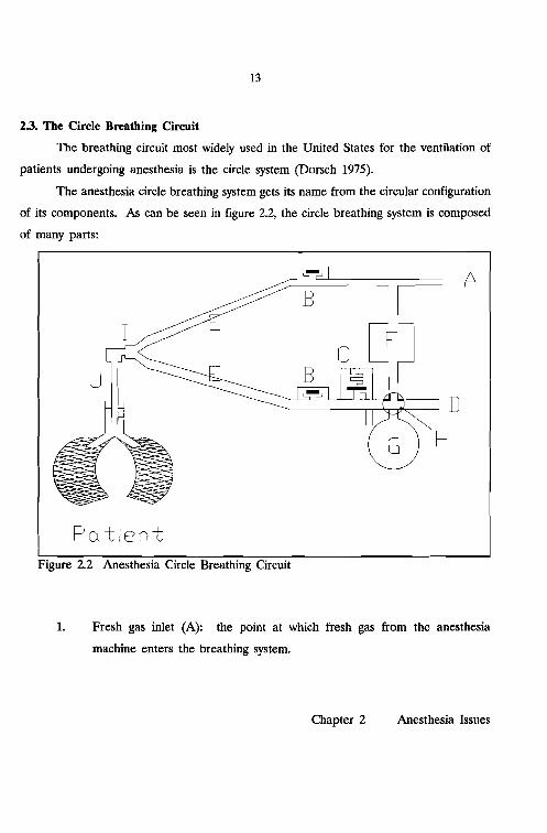
The breathing circuit most widely used in the United States for the ventilation of
patients undergoing anesthesia is the circle system (Dorsch 1975).
The anesthesia circle breathing system gets its name from the circular configuration
of its components. As can be seen in figure 2.2, the circle breathing system is composed
of many parts:
I
A
D
H
Figure 2.2 Anesthesia Circle Breathing Circuit
1. Fresh gas inlet (A): the point at which fresh gas from the anesthesia
machine enters the breathing system.
Chapter 2 Anesthesia Issues

14
...... Patient
DomeTwo unidirectional valves
(B): One of these valves is
inserted into the inspiratory
limb of the system, the other
one into the expiratory limb. Absorber +--This forces the gas to flow
into well defined directions.
These valves may consist ofFigure 2.3 Inspiratory Valve.
a rubber, metal or plastic
disk that sits in the valve seat. In the forward direction the disk is lifted
out of the seat allowing flow; reverse flow is blocked by the disk (figure
2.
2.3).
3. Adjustable Pressure Limiting Valve (APL or "pop-off' valve)(C): A valve
that limits the maximum pressure in the system to the selected setting and
vents excess gas from the system. A mechanical switch (H) removes this
valve from the breathing circuit during mechanical ventilation.
4. Ventilator connecting tube (D): connects the ventilator to the breathing
system.
5. Two corrugated tubes (E): These tubes make up the inspiratory and
expiratory limbs of the system. They keep resistance to a minimum and
should be highly unyielding to kinking.
6. Carbon dioxide (C02) absorber (F): The canister contains an absorbent
that scrubs any CO2 from the gas passing through, thus allowing rebreathing
of expired gases without the risk of CO2 build-up. Two absorbents are
Chapter 2 Anesthesia Issues

15
commercially available: soda lime, which contains a mixture of hydroxides
of sodium and calcium, and Baralyme, which is a mixture of hydroxides of
barium and calcium.
7. Breathing bag (G): This bag, also referred to as reservoir bag, allows the
anesthesiologist to assist or control breathing, if necessary, by manually
squeezing the bag, thereby forcing gas into the patient's lungs. During
spontaneous and manual ventilation a mechanical switch (H) removes the
ventilator from the circuit.
8. Connectors/adapters: The circle system is connected by means of a Y-piece
(I) to the mask or endotracheal tube (J).
The flow of gas during controlled ventilation is best explained starting with an
inspiration initiated by a mechanical ventilator. The ventilator forces a volume of gas
out of the ventilator bellows, through the ventilator hose and the canister with CO2
absorber, through the inspiratory limb, toward the patient. From the inspiratory hose,
gases pass through the Y-piece to the endotracheal tube and into the lungs. Much like
a balloon, the lungs fill with gas and expand. At the end of inspiration, when the
desired volume has been delivered, the positive pressure in the ventilator is removed
allowing exhalation to supervene. During expiration, the expanded lungs exhale passively,
forcing gas to flow through the expiratory limb, via the unidirectional expiratory valve
and toward the ventilator hose. Here the expiratory flow is joined by the continuously
flowing fresh gas. Together they make their way through the ventilator hose back into
the bellows. Once the bellows is filled completely, a pressure relief (exhaust) valve
located in the ventilator allows excess gas to escape.
To prevent pollution of the operating room, these excess gases are drawn into a
scavenging system and removed from the operating room. In general, the scavenging
Chapter 2 Anesthesia Issues

16
system is connected to the hospital's vacuum system through a manifold and relief valves.
A needle valve controls the flow rate of the removed gases.
Chapter 2 Anesthesia Issues

17
3. MONITORING DURING ANESTHESIA
Potent and potentially toxic drugs are necessary to induce anesthesia in patients
undergoing surgical, or painful diagnostic procedures. It takes a skillful anesthesiologist
to administer these drugs in such amounts to produce the desired effects while avoiding
potential hazards to the patient. Monitoring the patient facilitates the early recognition
of untoward trends and events. The anesthesiologist's primary resources to monitor a
patient are his sense of sight, hearing, smell, and touch (Dripps 1977 p:87). Relying
solely on these resources the clinician can gain ample insight in the state of the
anesthetized patient (Vandam 1985, Gravenstein 1986, Hug 1986 p:411-413). Yet, side
effects and accidents do occur (Cooper 1978, 1984, Craig 1981, Green 1984, Holland
1984). Apart from the ''why monitor" issue, immediately many other important
considerations should be raised including: what, where, how, and how often to monitor.
When is there too much or not enough monitoring, when does the risk of monitoring
outweigh its potential benefit, and when is the cost of monitoring no longer justified?
In this chapter a number of these issues will be addressed. We start with the
effects of anesthesia on the patient.
3.1. Why Monitor
It has been well recognized over the years that "Anesthetics are poisons, useful,
controllable, but dangerous" (Gravenstein 1979). The first successful public
demonstration of surgical anesthesia using inhaled diethyl ether vapor was performed in
Boston by William T. Morton in 1846, followed one year later by the introduction of
chloroform anesthesia by James Simpson. It was quickly recognized that anesthetics not
only produce anesthesia, but also have side effects on the patient. Ether first stimulates
and then depresses both respiration and circulation and, since it is explosive, can produce
definite calamities, while chloroform depresses both respiration and circulation and
damages the liver.
Chapter 3 Monitoring during Anesthesia

18
As early as 1848, Simpson himself described what appeared to be the first
anesthetic death attributed to chloroform (Simpson 1848). That monitoring was an
essential element of safety during the administration of anesthetic agents was recognized
almost from the beginning. James Syme stated that chloroform was safer than ether only
when properly administered and respiration was monitored (Sykes 1960). Syme's
emphasis on monitoring was well put, but some dangerous side effects of chloroform on
the liver cannot be monitored with current techniques, and the drug was taken out of
use.
Since the first demonstration of surgical anesthesia, an evolution propelled by the
introduction of a variety of drugs has taken place from the pure ether anesthetic to the
combination of inhalation- and IV drug anesthetics of today. The combination has
become possible with the introduction of neuromuscular blocking agents (e.g. d
tubocurarine in 1946 and succinylcholine in 1951), volatile inhalation agents (e.g.
halothane in 1956, enflurane in 1972 and isoflurane in 1981), sedative-hypnotic drugs
(including barbiturates like thiopental, and benzodiazepines like diazepam and rnidazolam,
and other categories as for example represented by propofol), narcotics (e.g. morphine,
meperidine, and fentanyl), and a new category represented by ketarnine. These drugs
are potent, potentially toxic, and not free from side effects and complications. In
addition, the effects brought on by these drugs vary among patients. Areas affected
include the cardiovascular system (i.e. depressed myocardial contractility, decreased or
increased blood pressures, decreased cardiac output), respiratory system (hypoventilation
secondary to central or neuromuscular depression), and parenchymatous system (liver and
kidney damage) (Julien 1984, Dripps 1977).
The potential toxicity and side effects produced by drugs used during anesthesia
are not the only sources for untoward effects on the patient's condition. Preexisting
diseases, for example, diabetes and hypertension, or extensive blood loss from trauma
already may have jeopardized the physical condition of the patient and his ability to
tolerate anesthesia and surgery. Clinical interventions by the surgeon and
Chapter 3 Monitoring during Anesthesia

19
anesthesiologist while intended to be therapeutic, sometimes can endanger the patient.
For example, artificial ventilation, blood loss, and fluid therapy are potentially hazardous.
Add to this the many possible positions the patient can be put in during surgical
procedures with the associated effects on circulation, tissue perfusion and alveolar
ventilation, and one can appreciate the difficulties that challenge the anesthesiologist.
Monitoring (from the Latin: monere, to watch) has therefore three equally
important aspects: 1) to aid in clinical management: for drug titration or ventilator setting
changes; 2) the identification of (primarily untoward) trends; and 3) to improve (or
maintain) patient safety: the early recognition and the estimation of the importance of
a potential problem. Monitoring requires that measurements are being made either
relying solely on the human senses, or augmented with optical, mechanical, pneumatic,
or electrical instruments. In terms of control theory, the anesthesiologist monitoring the
patient, is the feedback element in the control loop that constitutes anesthetic
management. (Ream 1979, Cooper 1979, Beneken 1983, Meijler 1987).
3.2. What to Monitor
Although it was recognized from the early days of the practice of anesthesia that
monitoring was an inherent element of anesthesia, what to monitor has been (and still
is) a controversial issue. Not every individual patient requires the same amount of
monitoring. There are 25 year old healthy athletes scheduled for the most benign
surgery under general anesthesia. These low-risk patients would require only a minimal
amount of monitoring. But what is minimal monitoring? What should always be
monitored and what is required in the non 25-year-old. Who determines what should be
monitored in each individual patient and how? These issues can be studied from the
viewpoint of what is needed and what is possible. But there are also other forces at
work, including how widespread a monitoring device is used and accepted by
anesthesiologists, the cost of the monitoring modality, and also pressures from the judicial
system mandating monitoring standards.
Chapter 3 Monitoring during Anesthesia

20
In the needed category, the clinician is concerned about the level of anesthesia,
ventilation, (removal of carbon dioxide (C02) and supply of oxygen (02»' the central
nervous system (brain, nerves, and cognitive functions), the transport system within the
body, (i.e. heart, circulation, and perfusion of other vital organs), body temperature, and
muscle relaxation function during anesthesia and surgery. The anesthesiologist's sense of
sight, hearing, smell, and touch are the primary resources to monitor the patient.
Instruments can not replace these clinical skills. From this, Pask concluded that the best
patient monitoring device was "a tube of contact adhesive: Place a small dab of it over
the patient's temporal artery, another small dab on one of the anesthetist's fingers and
bring these two into contact so that they could not be readily separated...." (Pask 1965).
The use of optical, electrical, mechanical and pneumatical devices, however, can
substantially augment and extend the clinicians ability to monitor the patient more
efficiently. The use of increasingly more monitoring instruments, with increasing
sophistication and their impact on patient care was questioned recently (Hamilton 1986,
Orkin 1989).
Additional monitoring modalities have become possible through technological
advances. New successful monitoring techniques are usually introduced in an effort to
solve immediate problems cost effectively. The development of monitoring equipment
has paralleled the advances of the electronics industry, although a lag was noticeable
(Schneider 1979).
The first monitoring standard was introduced because of a bet. At stake was a
dinner for giving the best anesthetic (Beecher 1940). To document this, both heart rate
and respiratory rate were recorded. In the early 1900's, it became practical to measure
blood pressure using the Riva-Rocci method combined with the changes in sound distal
to a slowly deflating cuff described by Korotkoff (Geddes 1966). Subsequently the
electrocardiogram (ECG), built upon Einthoven's original work but introduced as a
practical instrument in anesthesia in 1952 (Himmelstein 1952), gained wide applicability
and acceptance. Both ECG and arterial blood pressure have become standards and are
Chapter 3 Monitoring during Anesthesia

21
commonly used in evaluating the state of the cardiovascular system. Developments in
monitoring the central nervous system, respiratory system, neuromuscular blockade, and
temperature have brought an onslaught of monitoring techniques and instruments.
Initially, anesthesiologists adopted monitoring techniques because they presumed that the
patient would benefit. Indeed, several studies suggest, although after the fact, that
monitoring does increase patient safety (Cooper 1978, Amaranath 1979, Taylor 1980,
Cheney 1988, Eichhorn 1989). The American Society of Anesthesiologists (ASA) in 1986
defined and adopted minimal monitoring standards applicable to all anesthesia care (Am
Soc of Anes 1986). At the Harvard Medical School standards for patient monitoring
during anesthesia have been adopted since 1985 (Eichhorn 1986). Whitcher et aI. point
out that in addition to the moral imperative to monitor the patient, there is an
economical incentive to adhere to monitoring standards (Whitcher 1988). Recently
minimal standards also gained acceptance in Australia and New Zealand (Cass 1988).
In the following discussion we will adhere to the ASA standard. The ASA standard
states ''The patient's oxygenation, ventilation, circulation, and temperature shall be
continuous evaluated" and goes on to define the means.
Ensuring adequate levels of oxygen (Oz) concentrations in the inspired gas
requires the use of an 0z analyzer with a low 0z concentration limit alarm. The use of
a pulse oximeter is currently recommended to assess blood oxygenation, but will be a
requirement in 1990.
The ASA requires the adequacy of ventilation to be evaluated with qualitative
clinical signs. In addition, quantitative monitoring of carbon dioxide (COz) content
and/or volume of expired gas is recommended. When an endotracheal tube is inserted,
its correct positioning must be verified. Again, apart from clinical signs, the
measurement of end-tidal COz is recommended. If a mechanical ventilator is used
during controlled ventilation, a device capable of detecting disconnects in the breathing
circuit is mandated.
Chapter 3 Monitoring during Anesthesia

22
Adequacy of circulation shall be judged with the help of a continuously displayed
ECG, and of arterial blood pressure and heart rate each measured at least every five
minutes. In addition, continuous evaluation of at least one of the following is required
in patients under general anesthesia: palpation of the pulse, auscultation of heart sounds,
monitoring of a tracing of intra-arterial pressure, ultrasound peripheral pulse monitoring,
or pulse plethysmography or oximetry.
Finally, to aid in the maintenance of appropriate body temperature, the ASA
standard requires that the means to measure continuously the patient's temperature be
readily available.
It is evident that in encouraging these standards the emphasis is on patient safety,
and the implementation of these standards can be considered as guidelines for minimal
monitoring in the "25-year-old" low risk patient. Beyond the low risk group there are
many other monitoring modalities available, e.g., central venous and pulmonary artery
pressure monitoring, cardiac output monitoring, and the electroencephalogram (EEG).
These are indicated predominantly in patients considered at risk of suffering harm during
anesthesia because of the nature of the operation, or because of the patient's disease.
3.3. How often to Monitor
Monitoring is an ongoing actIVIty during anesthesia practice. Drugs are
administered and anesthetic gases and vapors are delivered based on the current level
of anesthesia compared to the desired, or projected level. The anesthesiologist must be
familiar with the effects of anesthetics and their time of onset and action in order to
control the level of anesthesia. In addition, knowledge of the pharmacokinetics of
administered drugs and insight in the uptake, distribution and excretion properties of
anesthetic agents is required. Monitoring for titrating the level of anesthesia does not
require frequent observations.
Drugs cause changes in monitored variables, as do clinical actions. Identification
of slow unidirectional changes in variables (trends) induced by drugs or clinical actions
Chapter 3 Monitoring during Anesthesia

23
require periods of intense monitoring, followed by stretches of potentially lower intensity.
For patient safety the identification of a trend or a change in a variable without
the trigger of a clinical action can be significant. The rate of change in signals and
variables can be different from trends secondary to clinical actions. Monitoring for
trends and significant events require frequent observations. If trends are identified, or
a potential untoward state is evident, monitoring becomes an unremitting endeavor with
even more frequent observations.
Causes for potential damage include insufficient oxygen to vital organs, stress
caused by the trauma of surgery and anesthesia, or excessive depth of anesthesia. It
takes only minutes before irreversible brain damage or even death can result due to
deficiencies in, or a total lack of, ventilation or circulation.
The American Society of Anesthesiologists has recommended in the adopted
monitoring standards, that blood pressure and heart rate are to be measured at most five
minutes apart (see paragraph 3.2 and Am Soc of Anes 1986). This has been the
traditional practice on the anesthesia record. Gravenstein et al. concluded that the five
minute interval is not frequent enough, and that the clinician might miss important events
(Gravenstein 1989).
3.4. How to Monitor
With the essential monitoring elements defined, the next issue is how to monitor.
The ASA standards hint toward the use of a number of specific monitoring instruments,
but leave enough leeway to accommodate many monitoring techniques.
Monitoring can be performed with or without the help of instruments,
noninvasively or invasively. Because of potential complications, which include bleeding,
infections, discomfort to the patient, and (even for a skillful clinician) the time consuming
placement of sensors, noninvasive monitoring is preferred. In the low risk patient
noninvasive monitoring is the technique of choice (Gravenstein 1987 p:3).
Chapter 3 Monitoring during Anesthesia

24
Much information about the condition of the patient can be gathered through
inspection, palpation, percussion and auscultation. Furthermore, all this information is
available noninvasively. Inspection of skin color or the color of the blood in the surgical
field can provide clues on the patients circulation, ventilation, and temperature. Other
prime areas suitable to be inspected include the patients eyes (tears are indicative of
light anesthesia), skin (hematomas), chest (chest motion with ventilation) and the volume
of blood loss. Palpation of an artery indicates rate and rhythm of a pulse, or allows the
evaluation of the patient's temperature. Percussion can be used to judge a suspected
pneumothorax, while auscultation can be employed to monitor heart sounds (rate, rhythm
and murmurs) and breath sounds (ventilation of both the lungs). Except auscultation,
where a stethoscope is frequently utilized, none of the previous techniques rely on the
use of instruments; many regard them as the foundation of monitoring. These
fundamental techniques are an integral part of the standards recommended by the ASA
(paragraph 3.2).
Instruments augment rather than replace clinical observations. The next sections
cover instruments utilized in the evaluation of the patient's oxygenation, ventilation,
circulation, and temperature as indicated by the ASA standards for basic intra-operative
monitoring, plus monitoring of the neuromuscular junction, included by many in the
minimal monitoring set (Ali 1986, Block 1986). Monitoring instruments, particularly
electrical and electronic instruments are referred to as: monitors. The same is done in
the following part of the text.
3.4.1. Monitoring Oxygenation
Whether the patient receives enough 02 can be monitored by measuring inspired
02 concentrations and the delivery of these 02-rich volumes to the patient. During
anesthesia inspired 02 concentrations are usually kept above 25%. Many of the oxygen
monitors currently commercially available employ measuring principles that have a slow
response time (1-2 minutes) to concentration changes and, in addition, are sensitive to
Chapter 3 Monitoring during Anesthesia

CO, [mmHg]so1
lClClOL
25
water vapor. Despite the slow response time, these instruments can still be used to
measure inspired concentrations to assure that enough 02 is present in the gas mixture.
When placed in the inspiratory limb of the breathing circuit (chapter 2), humidity is less
of a problem.
To assure adequate oxygenation of vital organs, the clinician measures the 02
levels in the blood. A number of techniques for measurement are available. Oximetry
exploits the differences in absorption characteristics of hemoglobin and oxyhemoglobin.
Clinically available oximeters have a sensor (with light-emitting diodes and photodiodes)
that easily fits on the ear, finger tip, or other perfused part that allows transillumination.
Pulse-oximeters have become very popular in the last five years. These instruments
employ oximetry in combination with the pulsatile (arterial) signal in the finger to analyze
(primarily arterial) hemoglobin. With this technique, 02 saturation of the arterial blood,
in addition to pulse rate and rhythm are available (Kelleher 1989).
3.4.2. Monitoring Ventilation
How well the patient's lungs are ventilated can be monitored with the help of
capnography. A typical capnogram, displaying the excursions of the CO2 partial pressure
in the inspired and expired gas mixture shows zero inspired partial pressures that are
followed by a quick rise toward a nearly
constant plateau throughout expiration
(figure 3.1). Deviations from the typical
capnogram indicate possible problems
origination in the patient (e.g. developing
shunt, light anesthesia, malignant
hyperthermia), breathing system (e.g. 15 ;.,.. [secl
leaks, unidirectional valve insufficiencies), Figure 3.1 Typical Capnogram showing the" . inspired and expired fluctuations in CO2ventilator (e.g. disconnects), or anestheSIa . I d . th· I
partJa pressures unng e resprratory eyc e.machine (e.g. leaks). The information
Chapter 3 Monitoring during Anesthesia

26
content of the capnogram is therefore high (Gravenstein 1989a). Capnographs measure
CO2 concentration by analyzing a gas sample obtained from a location close to the
patients mouth. Two types of analyzers are available: mainstream and sidestream. The
mainstream analyzer relies on a sensor that can be mounted in the breathing circuit,
while sidestream models aspirate a gas sample from the patient's breathing circuit.
Inspired and/or expired volumes can be monitored by observing the rise and fall
of the ventilator bellows (although the rhythmic movements of a hanging bellow can be
deceiving), and by mounting spirometers in the breathing circuit. Spirometers or flow
probes are used to quantify the gas flow.
3.4.3. Monitoring Circulation
The adequacy of the amount of blood perfusing vital organs cannot be monitored
with current technology. To make up for this deficiency, the electrical activity of the
heart, the ECG and arterial blood pressure are often monitored continuously. Blood
pressures are monitored at most five minutes apart if not continuously.
Noninvasive measurement of arterial blood pressures employ predominantly
occlusive techniques, commonly in the upper arm using an inflatable pressure cuff. At
first the inflated cuff occludes the artery. Then during slow deflation, the point at which
blood flow is reestablished can be detected. This is referred to as systolic pressure.
Further deflating the cuff allows mean arterial pressure and diastolic pressure to be
identified until unrestricted blood flow is possible again. Noninvasive techniques use
either auscultation, photo-electric, oscillometric or ultra sound based automatic devices.
A new method (the Pellaz method) employs a cuff around the finger (Pellaz 1976,
Boehmer 1987), which allows the continuous measurement of arterial pressures.
Invasive methods depend on the insertion of a catheter into an artery. Through
this canula, arterial pressure changes are transmitted continuously to a pressure
transducer, which converts the pressure signal into an electrical signal. When to use
Chapter 3 Monitoring during Anesthesia

27
invasive instead of noninvasive techniques in the light of possible complications and
indications is well described (Hug 1986 p:433-457, van der Aa 1983, Gravenstein 1989b).
The ECG traces the rhythmic electrical activity of the heart. From the ECG,
information on rate, rhythm, electrolyte changes in the body, and 02 supply to the heart
(ischemia) can be obtained. Commonly, skin electrodes placed in a number of possible
configurations can be used for diagnostic purposes (Kaplan 1986).
3.4.4. Monitoring Temperature
The body's ability to regulate its temperature is altered by most anesthetics making
the measurement of body temperature necessary. Temperature monitoring is based on
either mechanical, electrical or chemical principles. The common liquid filled
thermometers are considered impractical for use during anesthesia. Most temperature
sensors in current use are based on thermocouples or thermistors. Usually a temperature
probe is inserted into the esophagus, the nasolarynx or rectum, or attached to the skin.
3.4.5. Monitoring the Neuromuscular Junction
With the use of neuromuscular blocking agents, the degree of muscle relaxation
is assessed by monitoring the transmission of an impulse from a motor nerve to voluntary
muscle. In commercially available units, an electrical pulse through skin electrodes close
to the nerve stimulates the nerve. Typically, a single stimulus, a train of four, or a multi
second high frequency (tetanic) stimulus is applied; then the muscle's response (either
twitch or action potential) to the stimulus is subsequently gauged. Using this technique,
the degree of muscle relaxation can be adjusted as needed.
3.4.6. Vigilance
A vigilant anesthesiologist is considered the best monitoring device. "Anesthesia
vigilance" can be defined as a state of clinical awareness whereby dangerous conditions
are anticipated or recognized and promptly corrected (Gravenstein 1986a, Stoelting 1988).
Chapter 3 Monitoring during Anesthesia

28
With the help of monitoring instruments, the clinician's senses are augmented. However,
with the additional information, the clinician is taxed increasingly to remain on top of the
abundance of presented data. Factors that decrease a clinician's vigilance (i.e. fatigue,
distractions, or even boredom) have resulted in the implementation of alarm limits in the
monitoring instruments. A better approach to the concept of alarm limits is needed,
however. Chapters 4 and 5 will elaborate on this aspect.
3.4.7. Preoperative Information
The clinicians preoperative visit to the patient serves a number of functions. One
important reason is the gathering of pertinent information on the patient's medical
history, drug allergy, and current physical condition. Also, baselines for intraoperative
anesthetic management, against which intraoperatively measured variables are compared,
are established during the visit. Failure to evaluate the patient's condition preoperatively
has been shown to increase to risk of adverse complications (Amaranath 1979). As a
result of the preoperative visit, the clinician may elect to use more advanced or invasive
monitoring techniques instead of or in addition to the essential monitoring modalities
outlined in the previous paragraphs.
3.5. Signal Processing and Data Presentation
With the many measuring techniques introduced during the last twenty years,
more and more signals are obtained from the patient. In tum, each signal can produce
a number of derived variables (e.g. maximum, minimum, mean, rate of change) thus
increasing the amount of information that is presented to the clinician. In the essential
monitoring set, already ECG, blood pressure, capnography, temperature and pulse
oximetry signals are competing with the patient for the attention of the clinician. Each
signal produces a number of variables and in the case of the essential monitoring set
already up to 10 additional variables are calculated. Because each signal contains not
only information, but also may be fraught with artifact and/or transducer inaccuracies, the
Chapter 3 Monitoring during Anesthesia

29
signal curve is displayed for evaluation by the clinician. This increase in the number of
variables relevant for patient assessment is the first potential problem and is referred to
as the "information explosion" (Blom 1982, Beneken 1983). Merely providing the clinician
with more information will make it even more difficult to keep up with details.
Another problem closely related to the first is how to display all the data.
Commercial monitors in the majority of cases are dedicated to measuring only one signal.
Most of the time though, the real time display of the curve has to share available space
on the display unit with the derived or calculated variables. Each manufacturer is
compelled to implement a display layout capable of presenting the available information
as clearly as possible. However, the different manufacturers don't agree on the optimal
layout. Furthermore, simply placing monitors side by side does not provide an easy
overview of the relevant data.
The third problem, which is related to the second is that each signal is measured
and its results displayed by a separate unit. The space allotted to the anesthesiologist
and his basic instrumentarium: the anesthesia machine, breathing circuit, and intravenous
access routes, is already most of the time minimal for his extensive task. Additional
individual monitoring devices are, therefore, placed in such fashion to least infringe on
the available space: away from the patient.
Finally, one last problem with the current monitoring instrumentarium is the
danger that the anesthesiologist's attention might be drawn away from the patient and
toward the extensive monitoring facilities in order to evaluate the performance of the
equipment and the quality of the signals, to consider all information in their temporal
context, and, since many interrelations are present, to integrate all measurement results
in his mind.
It has been widely recognized that the uncontrolled proliferation of monitoring
devices has created problems in need of solutions. The increase in monitored variables
must be combined with multi-variable signal processing techniques (Beneken 1983).
Over the last two decades, a number of solutions have been proposed,
Chapter 3 Monitoring during Anesthesia

30
implemented, and evaluated, and have proven themselves invaluable along the path
toward a generic solution (Block 1985, Meijler 1987). Also, manufacturers have realized
the shortcomings of the current generation of intraoperative monitors and recent
announcements of new products are intended to address some of the problems. This
thesis describes additional steps contributing toward the ultimate goal of the development
of a truly integrated approach to monitoring.
Chapter 3 Monitoring during Anesthesia
31
4. ALARMS
An alarm is a warning of an approaching or existing danger. In anesthesia, an
alarm's main intent is to draw attention to a problem that can be solved before the
patient is harmed. The anesthesiologist caring for a patient and observing the monitoring
instruments can become alarmed by what he hears, feels, or observes. Many physiologic
monitors generate an alarm when a monitored variable traverses outside fixed, but
adjustable limits. The electrical or mechanical devices serving the alarm function by
generating a sound or signal, can help by offering a backup system to the already
overloaded, but vigilant clinician. Unfortunately, in present form, many alarms are not
perceived as helpful (Kestin 1988, Beneken 1989). This is clearly demonstrated by the
frequency with which alarms are silenced and ignored by annoyed clinicians.
This chapter examines why current alarm technology falls short in providing an
adequate backup system and why and how additional measures should be taken.
4.1. Current Alarm Technology
The alarm technology of the current generation of physiologic monitoring
equipment has several inherent problems. The idea to generate an alarm when an
individual variable exceeds static, but adjustable, thresholds is attractive in principle: one
simply sets applicable thresholds for that variable, and the monitor will alert when these
barriers are surpassed. However, with more variables being monitored and more
variables being able to trigger an alarm, it has become impractical to set all these
individual thresholds at the beginning, or during an anesthetic procedure. Many clinicians
rely on the manufacturer default settings, although these levels may not be appropriate.
The second problem is that current alarms are not specific. For example, there
is no unique, industry-wide blood pressure, heart rate, or oxygen saturation alarm. If only
a single alarm could be triggered, there would be no question about which variable is out
of bounds. With the increase in monitoring modalities though, the number of possible
Chapter 4 Alarms

32
alarms increases proportionally. This makes it much more difficult to identify which
variable(s) triggered an alarm.
The third problem merely emphasizes the non-specificity. Each manufacturer of
monitors has selected a tone, beep or buzz to get the clinician's attention. This means,
that one not only has to search for the sources setting off the alarms, but when multiple
alarms are generated the resulting mixture of sounds is very confusing.
Problem number four is the inability of the single variable alarm to point to
possible causes. For example, in those instances where a flat electrocardiogram (ECG)
causes an alarm, cardiac arrest, but also loose ECG electrodes, must be considered. This
is the prelude to problem number five.
Since single variable alarms are triggered by values exceeding thresholds, any
unwanted disturbance (artifact) in a signal can produce increases or decreases in the
value of a variable without an underlaying physiological cause. Artifacts can trigger an
alarm indiscriminately. The artifact category includes motion artifact (caused by patient
movement or repositioning), sensor fault (loose electrode or faulty pressure sensor during
noninvasive blood pressure measurement), calibration error (blood pressure transducer
not zeroed properly), and electrical noise (electrocautery, light source interfering with
sensor operation). Quality control of the physiologic signal, therefore, is crucial. The
clinician currently bears this burden by having to observe the real time waveform of the
signal.
Problem number six is the result of the "all or nothing" nature of almost all
current single variable alarms. Either an alarm is triggered, unconditionally and in full
force when a variable digresses outside the set thresholds or it is silent. When silent, no
early warning on developing problems are offered by the majority of the current
technology. (One example of an exception is the ''bar display" described by Meijler based
upon the principle of the "artificial horizon." It provides a global impression of the
behavior of up to ten variables over a period of up to three hours (Meijler 1987 p:42)).
Chapter 4 Alarms

33
More important, no indication regarding the urgency of the alarms is provided. To judge
the severity of the situation and to take appropriate action is left to the clinician.
This leads us to the final problem: how to set thresholds. If thresholds are set too
wide, an early warning of a developing, possibly deteriorating, trend will not be possible.
When an alarm finally is triggered, it could be indicative of an already serious problem.
On the other hand, when thresholds are set closely around a variable, frequent
unnecessary triggering of an alarm may result.
Combined, all these problems are responsible for the large number of false and
worthless alarms encountered in anesthesia. This was illustrated by Meijler, who analyzed
a total of 731 warnings generated by a statistical disturbance detection algorithm during
six cardiac operations (Meijler 1987 p:67-75). She concluded that, at most, 7% of the
detected disturbances generated useful warnings. Kestin et al. concluded that with 75%
of auditory alarms classified as spurious, an unacceptable high incidence of these alarms
occurred during anesthesia (Kestin 1988). False alarms cause the alarms on the monitors
to be silenced semi-permanently (McIntyre 1985), and adrenalin levels in anesthesiologists
to be elevated (Schmidt 1986).
4.2. Possible Improvements
There are a number of ways to improve current alarm technology. One idea is
to reduce false alarms by intelligent signal processing. Automated trend detection, the
use of redundancy, or other methods that exploit a combination of several variables are
examples of possible approaches.
Chapter 4 Alarms

34
4.2.1. Dealing with Artifact
As mentioned in paragraph 4.1, one major problem is artifact. During the
transition from physical variable into electrical signal, the transducer system can introduce
substantial errors. With analog signal processing, but even more so with digital processing
techniques and help from computers, more sophisticated signal processing has become
possible. The development of sophisticated signal processing techniques that automatically
detect artifact in signals is one approach to reduce false alarms caused by artifact.
4.2.2. Trend Detection
Slow unidirectional changes in signals (trends) can prompt the clinician to alter
management of the patient. Trends are caused either by spontaneous changes in the
patient, by the administration of drugs by the anesthesiologist, or by surgical intervention,
such as blood loss. Early detection of trends is important because trends give information
regarding the direction and rate of change in a variable. Unwanted trends should trigger
an alarm. On the other hand, when drugs induce anticipated and expected changes, no
alarm should be triggered. This leaves the dilemma of what to do if an anticipated trend
does not appear. Although clinicians recognize a trend when they see one, automated
trend detection and analysis are not without problems. This is because trends are
obscured by noise or natural fluctuation in the variable.
4.2.3. Multi-Variable Tactics
While the methods for automated artifact and trend detection concentrate on one
signal at a time, methods that use a combination of variables also show potential. Since
clinical decisions are rarely based on a single variable, these newer methods are a logical
step up. One essential element in the multi-variable techniques is the use of redundancy
among signals. For example, during anesthesia a patient's heart rate is obtained from
a number of independent monitors: the electrocardiograph, pulse oximeter and
Chapter 4 Alarms

35
(automated) noninvasive blood pressure monitor. Thus, three independent sources
observe and measure the same variable. In instances, when one source of heart rate
triggers an alarm, a quick cross check with the other two sources could confirm or reject
a positive alarm. Other multi-variable techniques combine different variables, e.g., heart
rate with changes in blood pressure.
Artifact rejection and multi-variable analysis make it possible to add intelligence
to current alarms, thus enabling reduction of false alarms, but also specific alarm
messages specifying what the problem is and where it is located, compared to the
nonspecific, obtrusive beep or buzz.
4.2.4. Integration and Communication
Multi-variable analysis presumes integration, which in turn presumes at least
communication between intraoperative monitoring equipment (if the variables are not
inherently integrated). But relevant information also comes from other sources, including
clinical laboratories, the preoperative evaluation, and radiology. For example, a
documented allergic reaction to certain drugs in some patients rules out the use of these
drugs. The patient's weight determines the initial selection of the minute volume (lO
IS cc per kilogram bodyweight at a rate of 10 breaths per minute) (Dripps 1977,
Gravenstein 1989a). Lower setting may result in hypoventilation. Existing cardiovascular
problems may determine the rejection of blood pressure and heart rate values for specific
patients, while similar reading would be considered acceptable for other patients. These
examples show that alarms should be evaluated in their proper context.
4.3. Toward Intelligent Alarms
Clinicians think in concepts. They reject apparent artifact, integrate information
from a wide variety of sources and are able to adapt to changes. If, for example, the
patient's end tidal carbon dioxide pressure (PetCOZ) increases, the clinician re-evaluates
the adequacy of ventilation by considering weight of the patient, and takes into account
Chapter 4 Alarms
36
preexisting pathological deficiencies, as well as a possible increase in the patient's
metabolic rate. If alarms are to be helpful, alarms must resemble this process.
In these terms, one could define intelligent alarms as any scheme providing helpful
interpretation of 1) the condition of the patient, 2) performance and condition of
monitoring and anesthesia equipment, 3) possible consequences of clinical actions and
interventions while taking into account a-priori information. The clinician is presented
with a helpful and meaningful message, that should include an indication of the possible
cause, location, and severity of the situation.
4.3.1. Fantasy or Possibility?
The inadequacy of many of the currently implemented alarm approaches has been
recognized, and in recent years, a number of schemes to improve alarm technology have
been proposed. Thus, the question whether intelligent alarms are wishful thinking or a
real prospect is academic: we can expect intelligent alarms in the future.
The fundamental problem of how to deal with artifact is being addressed.
Approaches include statistical methods, filtering techniques, frequency domain analysis,
and common sense (Jorritsma 1979, van Genderingen 1987, Rampill987, Beneken 1987).
Trend analysis methods have also been described (BJorn 1985). Using
microprocessors, signal processing in modem monitoring equipment has become quite
powerful and sophisticated compared to the "older" analog technology. For example,
modem ECG monitors are quite capable of dealing with high frequency electrocautery
artifact and some also have build-in S-T segment analysis or arrhythmia classification
routines. Other devices, such as some of the commercially available pulse oximeters, are
capable of detecting whether the sensor probe has been connected properly or has
subsequently become dislodged.
Redundancy and multi-variable techniques are being developed and used, although
on a small scale. As early as 1968, Raison et a1. described how to reduce the number
of false alarms in an intensive care unit using the correlation of two variables (Raison
Chapter 4 Alarms

37
1968). Fukui described an intelligent alarms system in use during cardiopulmonary
bypass, that used three independent signals (Fukui 1987). However, monitoring
equipment has begun to appear on the market taking advantage of redundancy and multi
variable analysis only very recently. For example, the Critikon's integrated (Critikon
Tampa, Fl.) pulse oximeter/non-invasive blood pressure monitor employs a scheme not
to trigger an alarm when the pulse oximeter sensor is unable to pick up a signal
secondary to cuff inflation during noninvasive blood pressure measurements on the same
extremity.
Redundancy and the use of multiple signals have been proposed by others as a
natural step toward the reduction of detrimental alarms (Kunz 1975, Osborn 1982,
Gravenstein 1987 p:387-389, Beneken 1989).
Communication and integration is also being addressed. The definition of a
medical information bus (MIB) that specifies a local area network to acquire data from
monitoring equipment, anaesthesia equipment, and intravenous pumps is nearing
completion (Shabot 1989). These standards are being developed by the Institute of
Electrical and Electronic Engineers (IEEE) and prototypes based on the MIB are being
implemented (Gardner 1989).
In addition, manufacturers of anesthesia and monitoring equipment are beginning
to answer the demands for integrated anesthesia equipment. A number of these new
generation anesthesia machines and monitoring devices are beginning to appear on the
market from various vendors (American Draeger, Hewlett-Packard, and Ohmeda). These
machines address the pressing needs of better intraoperative anesthetic management and
alarms. It should be noted that these developments are a result of the numerous efforts
by research teams (Cooper 1978a, Gardner 1982, Block 1985, Meijler 1987).
Chapter 4 Alarms

38
4.3.2. The Layered Approach
Intelligent signal processing that produces reliable and reproducible data is a
fundamental prerequisite for intelligent alarm systems, as is the ability to integrate.
Measurements are obtained from physical variables transduced into an electrical
representation. But, the sheer amount of information in these continuous signals is
unworkable. Thus, both qualitative and quantitative features have to be extracted from
the original signal. Artifact rejection and multi-variable analysis (section 4.2) are the
necessary and essential elements of attacking signal analysis.
To present the clinician with helpful intelligent alarms, the following layered
approach toward intelligent alarms, which emphasizes data reduction without loss of
essential information would provide the necessary framework (Figure 4.1).
3
2
1
IPresentation Layer 7
Message Shell 6
Smart Alarms 5
Redundancy Removal 4
T 0 000 TTrend Analysis Trend Analysis
Feature Extraction 0 0 Feature Extraction
Signal Acquisition Signal Acquisition
3
2
1
Figure 4.1 Possible Framework for a Layered Approach to Intelligent Alarms.
At the lowest level resides the transducer system with sensors, amplifiers, filters,
and calibration components. These components transduce the physical variable into an
electrical signal. At this level not only is the electrical signal available, but also status
information about the transducer system. These include: transducer present/not present,
Chapter 4 Alarms

39
working/not working, calibrated/not calibrated, connected/not connected, etc. All this
information is passed to the second level, feature extraction.
At the second level, signal features are extracted to reduce the amount of
information; most commonly, a digital computer hosts signal processing software
responsible for data reduction of the signal into a set of derived features. These features
should describe the original signal as completely as possible. Examples include maximum,
minimum, frequency spectrum, area under the curve, timing information, slopes. Signal
validation is also performed at this level, which entails a comparison of the set of derived
features with previous sets of features. These sets are learned over time and stored into
local computer memory. They may be fixed, based on common knowledge about the
signal, or adaptive, based on the behavior of the original signal. Other tests look at
feature values in terms of absolute value (e.g. a systolic blood pressure of 500 Torr is
non-physiologic) and rate of change. The results of analysis on this level both in terms
of the set of features plus associated status information is transferred to the next level.
It should be noted that not necessarily all features are passed to the next level; features
extracted solely to aid in validation are omitted.
On the third level trend analysis per feature is performed. The time of onset and
direction of the trend are calculated. Corresponding status information augments the
trend information and are added to the feature information set. At this moment, all
information that can be extracted from one signal expressed in features is extricated from
the signal and available to be passed on to subsequent processing levels.
The previous three levels described work with only one signal and its derived
features. The fourth level, receiving features and status information from the lower levels
from different signals is the redundancy removal level. Here, superfluous data are
omitted from the pool of feature information, before being passed to the next level. For
example, of the three heart rate values, one value with status information regarding
validity and quality is transferred to subsequent levels.
Chapter 4 Alarms

40
On the fifth level, where the heart of the intelligence resides, smart alarms are
generated. This level looks at variable features and values, trends, combinations of
variables, and determines if problems exist, where they occur, and their plausible cause(s);
and, if applicable and appropriate, suggests how to solve the problem. In order to make
this level as intelligent as possible, as much a-priori information as feasible should be
made available. This includes patient demographic data (e.g. sex, age, height, weight),
preoperative evaluation information (e.g. known allergies, cardiovascular and pulmonary
historical data, smoking habits), and intraoperative information, including clinical
interventions such as drug administration (e.g. what drug, amount, timing and
pharmacokinetics of drugs given to induce and maintain anesthesia or therapy),
readjustment in ventilation (changes in fresh gas flows, tidal volume), position of the
patient (e.g. Trendelenburg, supine), and fluid balance (e.g. loss and input by amount,
rate, timing, and composition).
Level six is the message shell, which determines what (if any) message to send to
the clinician about the patient and the equipment: for example "Suspect Hypoventilation,"
"ECG lead disconnected," "Heart rate falling fast," and also "High end-tidal CO2 values.
Cause unknown." If more than one possible cause should be considered, the messages
should preferably appear in order of likelihood. Much like a clinician would assess the
situation, these messages are scored on a scale from "high priority" to "low priority," from
"need to act" to "need to observe."
Level seven is the final layer: the presentation. This level receives its inputs from
level six, but also might display real time signal waveforms, trend information, pertinent
patient demographics, and other data on a central, integrated display used for interaction
with the anesthesiologist.
Chapter 4 Alarms

41
4.4. Limits and Alarms
It was argued in this chapter that many of the prerequisites for an intelligent
alarm technology are feasible, developed, or currently under development to allow the
layered approach to be implemented, although the three top layers require additional
work. To add intelligence, to select which is the most appropriate message and under
what condition, and to define the man-machine interface requires imaginative solutions.
As Beneken points out, decisions made with signals, trend variables, and multi
variable analysis, are based upon comparisons with reference values; they are either static
or variable over time (Beneken 1989). This means that too many reference values must
be set for too many variables for too many patients under too many circumstances.
While all problems have not been solved, it is reasonable to help the clinician as much
as is currently feasible. When useful messages can be generated, we should and will do
so.
Chapter 4 Alarms

42
5. IMPLEMENTING INTELLIGENT ALARMS
We have identified the clinical problems the anesthesiologist tries to solve through
monitoring: 1) titrating the level of anesthesia, 2) untoward trend identification, and 3)
patient safety (chapter 3). It was argued that current alarms do not help the clinician,
and problem areas were identified. A layered approach to intelligent alarms (chapter 4)
was subsequently presented as a possible framework for an implementation. In this
chapter, arguments for concentrating on the patient's ventilation are discussed for the
implementation of our version of intelligent alarms. Possible approaches are compared,
and reasons for selecting the expert system approach are given. A frame work for the
implementation concludes this chapter.
5.1. Monitoring for Patient Safety
The anesthesiologist's main concern for patient safety is irreversible damage to the
brain, heart, lungs, liver, and kidneys. Insufficient oxygen supply to the organ is the
primary concern. Tissue hypoxia can be the result of ventilatory, circulatory, metabolic
or toxic effects. When clues indicate that patient safety might be in jeopardy, the
anesthesiologist diagnoses the possible causes, assesses the implication for the patient, and
selects and institutes a treatment. In the following discussion metabolic and toxic factors
will be ignored. The focus will be on respiratory and circulatory factors.
5.1.1. Detecting Potential Problems
It takes only minutes before irreversible brain damage or even death can result
due to deficiencies in, or a total lack of, ventilation or circulation. Therefore, the
identification of a trend or a change in a variable, particularly those without the trigger
of a clinical action, can be significant and must be detected. Patient monitoring, with or
without the aid of instruments, enables the early recognition of changes in a variable or
the detection of a trend (chapter 3). However, it is clinically nearly impossible and
impractical to monitor the condition of the patient continuously and in every detail, even
Chapter 5 Implementing Intelligent Alarms

43
with monitoring devices. That is why alarms should advise the clinician of untoward
situations.
5.1.2. The Differential Diagnosis
When a potential problem arises, time can be essential, and the anesthesiologist
must act swiftly to uncover and treat the cause, as the origin is either iatrogenic, related
to equipment, produced from within the patient, or caused by artifact, much valuable time
can be spent making a differential diagnosis of the problem. First, artifact must be ruled
out. Then the anesthesiologist inspects the surgical field, evaluates actions of himself and
of the surgeon. The anesthesia machine, the breathing circuit, and other anesthesia
equipment are examined while evaluating monitored variables for clues of equipment
failure or a problem within the patient. As an illustration, the differential diagnosis for
hypoxemia is examined in more detail.
An Example
Hypoxemia can be limited to an organ, for example hypoxia of the brain after
occlusion of the blood supply to the brain, it can affect all organs if blood flow in general
becomes inadequate, or it can be the result of insufficient oxygen in arterial blood. The
latter circumstance is of interest here; it can result from: 1) hypoxic inspired gas mixture,
2) hypo-ventilation, or 3) a mismatch of ventilation to perfusion (Gravenstein 1990). The
primary indication of hypoxemia is provided by the pulse oximeter, assuming circulation
is intact.
After determining that artifact is not the culprit of the lowered saturation reading,
and that the monitor is functioning properly, the process of finding the cause begins.
This searching process can be presented as the following list of questions (in a "pseudo
language"). The sequence in the list indicates a priority.
Chapter 5 Implementing Intelligent Alarms

44
Ad 1) Consider hypoxic inspired gas mixture.
Is the fraction of inspired gas (Fi02) >= 21%? If not, consider:? adequate oxygen (02) delivery
- Check 02 gas supply pressures- Check gas flow settings on anesthesia machine- Check flow meter on anesthesia machine- Check anesthesia machine for leaks- Check for obstructed fresh gas supply line
? contaminated 02 supply- Check for misconnection(s) at the anesthesia machine- Check for wrong gas in pipeline
Ad 2) Consider hypoventilation
Look at the capnogram. If no capnogram present consider:? disconnection
- Check pressures in the breathing system- Check all connecting points in the system
? esophageal intubation- Check position of endotracheal tube (ET)
? mechanical ventilation present- Check mechanical ventilator for proper operation
? occlusion- Check for gas flow in breathing system- Check unidirectional valves- Check for presence of foreign body in the system- Check pressures in the breathing system
If a capnogram can be observed, consider:? leaks
- Check pressures in the breathing system- Check all interconnections for leaks- Check ET cuff for leaks
? obstructions- Check pressures in the breathing system- Check for a kink or other obstruction in the ET
Chapter 5 Implementing Intelligent Alarms

45
? CO2 rebreathing- Check for valve insufficiency- Check for exhausted CO2 absorber- Check possible rebreathing valve
? adequacy of ventilation- Check tidal volume. Is it adequate for this patient?- Check for increased dead space
? increased CO2 production- Check for hyperthermia/malignant hyperthermia
Ad 3) ventilation to perfusion mismatch
The partial pressure of 02 in arterial blood is less than that in alveolar gas:? Endobronchial intubation
- Check breath sounds- Check position of ET
? Occlusion in the lung due to mucus or aspirated stomach contents- Check for foreign bodies in the bronchia
? Patient's position has changed- Check position of the patient
? Embolism- Check for clues of embolism due to air, blood clot, fat, or tumor- Check trend in end-tidal CO2
? Pulmonary diseases- Check patient history- Check for partial occluded airway
? Surgical interference- Check surgical field
5.1.3. Implications and Treatment
The example in section 5.1.2 not only illustrates the many potential causes to be
evaluated in a short time period, it also hints at the range of implications for the patient,
and at possible different treatment strategies. In both instances, differential diagnosis is
the key that determines the next course of action. Immediate action is indicated in case
of hypoxic gas mixture, while a change in the position of the patient could result in no
treatment. As treatment is the territory of the clinician, an intelligent alarm system
Chapter 5 Implementing Intelligent Alarms
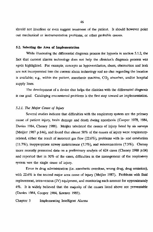
46
should not interfere or even suggest treatment of the patient. It should however point
out mechanical or instrumentation problems, or other probable causes.
5.2. Selecting the Area of Implementation
While illustrating the differential diagnosis process for hypoxia in section 5.1.2, the
fact that current alarms technology does not help the clinician's diagnosis process was
again highlighted. For example, concepts as hypoventilation, shunt, obstruction and leak
are not incorporated into the current alarm technology and no clue regarding the location
is available; e.g., within the patient, anesthesia machine, CO2 absorber, and/or hospital
supply lines.
The development of a device that helps the clinician with the differential diagnosis
is our goal. Cataloging encountered problems is the first step toward an implementation.
5.2.1. The Major Cause of Injury
Several studies indicate that difficulties with the respiratory system are the primary
cause of patient injury, brain damage and death during anesthesia (Cooper 1978, 1984,
Davies 1984, Cheney 1988). Meijler tabulated the causes of injury listed by six surveys
(Meijler 1987 p:146), and found that almost 50% of the causes of injury were respiratory
related, either the result of incorrect gas flow (22.6%), problems with in- and extubation
(11.7%), inappropriate airway maintenance (7.7%), and misconnections (7.3%). Cheney
more recently presented data on a preliminary analysis of 624 cases (Cheney 1988 p:14)
and reported that in 30% of the cases, difficulties in the management of the respiratory
system was the single cause of injury.
Error in drug administration (i.e. anesthetic overdose, wrong drug, drug omission),
with 22.6% is the second major area cause of injury (Meijler 1987). Problems with fluid
replacement, intra-venous (IV) equipment, and monitoring each account for approximately
4%. It is widely believed that the majority of the causes listed above are preventable
(Davies 1984, Cooper 1984, Keenan 1985).
Chapter 5 Implementing Intelligent Alarms

47
Not all injuries can be prevented, however. A poor physiological status of the
patient, pathological causes, and other factors beyond control present inherent risks.
5.2.2. Suggested Improvements
With human error and equipment failure accounting for the majority of injuries,
approaches to minimize their occurrence have been proposed (Cooper 1984). Additional
training, more complete preoperative assessment, additional monitoring equipment,
improvements in the man/machine interface, and better supervision were among the
suggestions made toward detection and prevention. In the meantime, helpful monitoring
modalities have become available and have been put to use. Minimal monitoring
standards have been adopted, quality assurance programs have been instituted, and
man/machine interface issues are being addressed (Cooper 1978a, ASA 1986, Meijler
1987, Eichhorn 1989, Schreiber 1989).
5.2.3. Scope of the Project
It must be clear from all that is mentioned so far, that the advanced monitoring
facilities are brought on, in part, by the increased sophistication of surgery, and through
advances in commercial equipment. Notwithstanding the additional monitoring modalities,
the current alarm technology still proves to be a major weakness. The sheer vastness
and complexity seems to have reached the limits of comprehension by the
anesthesiologist. It is our intention, in the long run, to hide all monitoring details from
the anesthesiologist and to present him (her) with a higher abstraction level of the
patient. Essential, however, is the availability of all pertinent qualitative and quantitative
information, in order to home in on the problem area. Toward this goal, integration of
information and intelligent alarms are steps toward the detection of changes in the state
of the patient and to aid in the differential diagnosis process.
Chapter 5 Implementing Intelligent Alarms

48
With the identification of the area where most causes of injury are to be found,
the stage is set to define the scope of the project: smart alarms concerning ventilating
patients under anesthesia.
5.3. Project Approach
The fundamental idea is, that an analysis of clinical important decisions by
clinicians (while making the differential diagnosis) during critical incidents concerning
ventilation, constitutes the basis for the development of smart alarms. In selecting an
approach for the implementation of the Intelligent Alarm (IA), a number of issues are
important. This section describes design criteria, compares possible approaches and
selects the approach of our project.
5.3.1. Design Criteria
There are several properties (or attributes) the IA system should possess, most
of them discussed in chapter 4. Apart from reducing the number of false alarms and
presenting the clinician with helpful messages identifying the encountered problem in
terms of severity and location, the system should work in real time. For our application,
real time means that the system should have recognized an external event and produced
a response by the time it is required clinically. Real time in our context also requires
the ability of the system to respond fast enough to external events, as the presence of
new or updated data from front-end monitoring devices, or pressing a key on a keyboard.
Finally, the IA system should provide both a practical and economical solution to the
problem.
Chapter 5 Implementing Intelligent Alarms

49
5.3.2. Possible Approaches
Even though the onset of a potential complication can be signaled by a change in
only one monitored variable, the differential diagnosis is based on multiple signals and
variables. Few approaches currently exist that interrelate different signals and variables.
One approach suggested by Beneken and Gravenstein introduces the concept of fault
models (Beneken 1987). In this approach, a three digit classification is associated with
each variable indicating its static, dynamic and statistical properties. Each fault model
(e.g. an arterial catheter flush, loose electrodes) is subsequently expressed in terms of
combinations of these three-digit classifications. An algorithm identifying fault models
would notify the clinician of a present or impending problem.
A variant of the fault model approach is to identify a potential problem as a
pattern of "n" digits; one digit per variable or derived feature. Like Beneken's approach,
concepts as: too high, elevated, normal, depressed, too low would be mapped into a digit.
A potential problem would be expressed as an n-digit number, which could be compared
with the current n-digit number of signals and features.
The methods above can be considered as examples of a more general pattern
recognition approach. Pattern recognition generally entails, that a set of characteristic
features is extracted from input signals. These features are operated upon such that each
of the patterns to be recognized produces an output which is as unique as possible. The
n-tuple input pattern is mapped to a m-dimensional output space. For "n" features there
is an m-dimensional space in which normal and problem areas can be discriminated.
Location of the feature set in one of the problem areas provoke associated alarms.
Examples of the use of pattern recognition for displays have been made by Siegel, who
suggested a circle diagram for physiologic states (Siegel 1983), and Meijler, who presented
the "bar display" of up to ten patient variables (Meijler 1987 p:42).
Application of the Fuzzy Set Theory (Zadeh 1965) is another approach to
consider. Fuzzy logic is used to model human reasoning which by nature is saturated
with imprecise concepts. The Fuzzy Set Theory can be seen as a generalization of the
Chapter 5 Implementing Intelligent Alarms

50
classical set theory, in which an element either belongs to a set or it does not. The key
idea in the Fuzzy Set Theory is that an element belongs to a set expressed as a degree
of membership. For example, consider the set of tall individuals. A person who is four
feet tall would have a degree of membership of 0, while a seven feet tall person's degree
of membership would be 1. Intermediate heights have a degree of membership between
o and 1. Examples from the world of anesthesiology include: "heart rate is high,"
''ventilation is adequate," "this is a young patient," and "blood pressure is stable." The
membership concept is related to the concepts of "probability" and "certainty."
The only other possible approach that will be mentioned here is the use of an
expert system. Much like human experts, expert systems solve problems in a certain area
of expertise. Expert systems differ from algorithms in that rather than a set of
operations, procedures, and decisions, a heuristic is used. A heuristic is a rule of thumb,
a trick, or a simplification of the problem to aid in finding a solution to the current
problem. In addition, the knowledge about the problem to be solved (the knowledge
base) is kept separately from the knowledge of how to solve problems (the inference
engine). In algorithmic approaches, knowledge and procedural knowledge are integrated
into the algorithm. Intuitively, smart alarms and expert systems are interrelated.
Anesthesiologists, through increasing knowledge and experience that is gained over many
years of practice, become experts in the field. The differential diagnosis process is an
illustration of the expert at work. The expert systems approach will be looked at in more
detail in the next section.
5.3.3. The Expen Systems Approach
Before embarking on the expert system approach, it is necessary to evaluate
whether expert systems are appropriate for helping physicians determine the cause of
problems. The most appropriate problems for expert systems are heuristic in nature
which use symbolic reasoning. The problem area must be sufficiently narrow in scope,
must be manageable and must have practical interest (Waterman 1986 p:131-134).
Chapter 5 Implementing Intelligent Alarms

51
Shortliffe, one of the pioneers in the field of expert systems in the medical field, suggests
a number of criteria (Shortliffe 1982), including: 1) physicians must recognize the need
for assistance, in particular computer assistance, 2) medical expertise and experts must
be available and accessible, 3) mechanisms must be in place to introduce the tool into
the clinician's daily routine, 4) clinicians must maintain the final say in the decision
process, 5) clinical participants in the project must be highly motivated, and 6) the
problem to be solved must be well understood.
Using these criteria as a guide in our evaluation, led us to believe that the
approach is appropriate. As mentioned before, physicians recognize that functional
integration of information from monitoring devices, and integration of alarms in particular,
is helpful. Alarms pertaining to ventilation of patients under anesthesia is an area of
particular interest in the Department of Anesthesiology at the University of Florida
(Beneken 1985, 1987a, van Genderingen 1987, Good 1988, Gravenstein 1989a, 1990).
Initially, the scope of the project concerns itself with a limited number of potential
problems and concepts. The availability of an anesthesia simulator designed to reproduce
the working environment of the anesthesiologist while reproducibly creating a number of
undesired situations, specifically during mechanical ventilation, is particularly attractive
during the development (Good 1988, Hekker 1989). Finally, laboratory and operating
rooms are readily available and accessible.
Another important consideration favoring the expert systems approach over
conventional programming is the separation of the knowledge from the reasoning
techniques with that knowledge as it is inherent in expert systems (chapter 6). Keeping
the knowledge separate facilitates concentration on the knowledge which makes it possible
to represent the knowledge conveniently, to discuss the knowledge with the expert. This,
in turn, can improve modularity, transparency and ease of maintenance.
Given these considerations, it is reasonable to embark on the expert systems
approach for the intelligent alarm system outlined in paragraph 5.2.3. that assists the
clinician with alarm management during anesthesia.
Chapter 5 Implementing Intelligent Alarms

52
6. EXPERT SYSTEMS
Ever since ENIAC, the first digital computer, made its entrance in 1946, man has
looked for ways to make computers behave like intelligent human beings. In 1956, John
McCarthy organized the Dartmouth conference and introduced the term Artificial
Intelligence. This conference is uniformly regarded as the birth of that part of computer
science research concerned with intelligent computers: artificial intelligence (AI). One
practical definition of AI was offered by Winston: "Artificial Intelligence is the study of
ideas that enable computers to be intelligent" (Winston 1977 p:1). Tracing the path of
AI in history, Jackson identifies three periods: the Classical period, the Romantic period
and the Modern period (Jackson 1986). For the first ten years (the Classical period), AI
research concentrated on the quest for a general purpose problem-solving algorithm that
was the key to all human intelligence. Despite initial promising results (Feigenbaum
1965), researchers, in the following decade (the Romantic period) concentrated their
efforts on making computers understand natural language and methods to represent
knowledge in a computer. Methods to reason with the knowledge representations also
gained much attention. Many papers from this period can be found in Winston (Winston
1975). Toward the end of the 1970s (the Modern period), researchers, somewhat
disillusioned with the general problem-solving techniques, realized that it was impossible
to develop a general purpose algorithm for the broad spectrum of problems. The
conviction grew that problem-solving power of intelligent computer programs results from
incorporated, explicit, relevant knowledge. According to Waterman: "To make a program
intelligent, provide it with lots of high-quality specific knowledge about some problem
area" (Waterman 1986). This realization led perhaps to the most exciting areas of
Artificial Intelligence research in recent years: the expert system. Many useful and
successful applications of expert systems in such areas as chemistry, medicine, geology,
and computer hardware have resulted (Martin 1971, Shortliffe 1976, Fagan 1980, Lindsay
1980, McDermott 1980).
Chapter 6 Expert Systems

53
This chapter presents a brief introduction to expert systems, followed by a
description of the expert system tool SIMPLEXYS that was used to implement the
intelligent alarm application.
6.1. Introduction to Expert Systems
An expert system is a computing scheme that combines knowledge, facts, and an
inference technique to solve problems in a well defined domain in a way human experts
would (Waterman 1986). In layman terms, an expert system is a computer program that
mimics an expert in a specific narrow field (domain) by applying a problem solving
technique (the inference technique) to the knowledge gathered from the expert.
Therefore, expert systems, like the human expert whose knowledge is implemented, make
the same mistakes and do not guarantee a correct answer, but increase the likelihood
to find a useable answer.
By capturing the expert's knowledge, which is generally expensive, perishable,
scarce, and difficult to document and transfer, expert systems make this knowledge
affordable, permanent, abundant, and easy to document and transfer. Consequently,
expert systems are becoming cost effective alternatives in a variety of areas requiring
experts to solve problems.
6.1.1. Expert System Components
The internal structure of an expert system consists of, the knowledge base, a data
base, an inference engine, and a user interface (figure 6.1).
The Knowledge base
The knowledge base in an expert system contains facts and the domain knowledge
(heuristics) for the decision making process. Note that the knowledge base is a separate
entity. The domain knowledge can be represented using a number of approaches.
Chapter 6 Expert Systems

54
Widely used are representation schemes using rule-based methods, structured objects, and
predicate calculus (Jackson 1986).
Inference Engine
Figure 6.1System.
Components of an Expert
Rules (also called production rules) are of the form:
IF premise 1 AND premise 2 AND ...
THEN action 1, action 2,
If the premises of the rule are satisfied, the actions specified by the THEN part are
performed. The action part may in tum invoke another rule, and so on. When the
knowledge is stored using a rule-based method, the knowledge base is also referred to
as the rule base. Many expert systems are rule-based, because these kind of rules are
easily understood, and easy to implement.
Structured objects include a number of representations such as 1) semantic nets,
a constellation of nodes and links in which a node stands for a specific concept and the
links describe the relationships between the nodes, 2) frames, a network structure of
nodes and hierarchical relationships in which each node is described by a collection of
slots (attributes), and 3) decision trees, a hierarchical semantic network where the nodes
represent goals, and the links represent decisions.
Chapter 6 Expert Systems

55
Predicate calculus consists of a language for expressing propositions, and rules that
prescribe how to infer new propositions from existent ones. Possible inferences include
deductions, abductions, and inductions. An example of a deduction:
Proposition 1: BASIL is a cat
Proposition 2: All cats are black
From these two propositions, we deduce that BASIL is a black cat.
The Data Base
For temporary storage of external inputs to, and intermediate results of the
inference process, scratch-pad storage is provided by the internal read/write memory.
Since expert systems are implemented using computers, the computer's internal memory
usually serves that purpose.
The Inference Engine
The inference engine is the mechanism that contains the problem solving
knowledge and performs the reasoning. The inference engine uses the knowledge in the
knowledge base plus information provided by users (interactive applications), data
acquisition equipment (process controllers), or databases to infer. Examples of reasoning
strategies include forward chaining, backward chaining, pattern matching, or one of a
variety of searching techniques.
The User Interface
The user interface is the part of the system that enables the user to communicate
with the expert system and visa versa in a friendly and flexible way. Entering facts about
a particular situation, questions within the system's subject domain, and responses to user
requests are all handled by the user interface. Some expert system shells provide a
graphics interface in the form of a lattice (a visual representation of the logic flow) to
aid in the expert system development. For example the Automated Reasoning Tool
Chapter 6 Expert Systems

56
(ART) provides this mechanism (ART is a product of the Inference Corporation, Los
Angeles CA). The lattice can also be used to provide the user with visuals of the
inferencing process. Examples of implemented user interfaces include natural language
dialogue, graphics interface, menus, explain facilities, or a "window" environment with non
keyboard entry devices, such as a mouse or track-ball.
6.1.2. Building an Expert System
Designing and building an expert system is called knowledge engineering; the person
performing the activity is called the knowledge engineer. The knowledge engineer interacts
with the human expert, the domain expert, to obtain the knowledge to solve problems
in a specific domain; this is called knowledge acquisition.
Knowledge is acquired from a number of sources, including textbooks, databases,
and personal experience, but the main source is the domain expert. The knowledge
transfer from the human expert into an expert system is the key element in development.
Typically, a series of intense interviews between knowledge engineer and domain expert
is the method of choice, although other methods have been attempted, including on-site
observation, video-taping, and simulators. Building a knowledge system is an iterating,
evolutionary process in which five major stages of identification, conceptualization,
formalization, implementation, and testing can be identified (Hayes-Roth 1984). After
initial sessions with the domain expert, the knowledge engineer will have identified the
problem and after finding concepts to represent the knowledge and structures to organize
it, he or she builds a prototype of the expert system. This prototype is tested and
discussed with the domain expert and, over the course of many sessions, refinements are
made, and new prototypes built and rebuilt, until all involved are satisfied.
Chapter 6 Expert Systems

57
6.2. Expert Systems Applications in Medicine
Since the birth of expert systems, medicine has provided a challenging field for
applications, but the few applications currently in use deal with relatively simple tasks
(Gardner 1986). Over the last twenty years, a number of investigators have developed
medical AI systems to assist the clinician primarily in the area of consultation (Kulikowski
1988). The most renowned results are: MYCIN, which gives advice on the diagnosis and
treatment of bacterial infections in the blood, and meningitis (Shortliffe 1976);
INTERNIST, which given a patient's history, symptoms, or laboratory results assists in the
diagnosis process in general internal medicine (Miller 1982); and PUFF, which aids in the
diagnosis and assesses the severity of pulmonary disease (Aikins 1983). Other
applications followed, such as ONCOCIN, which advises physicians who care for patients
on chemotherapy protocols (Shortliffe 1984); and ATTENDING, a critiquing system that
gives advice for anesthetic management (Miller 1983). These expert system applications
are examples of systems in domains with static data, and no requirement for time critical
responses.
More recently there is an interest in applications of real-time expert systems to
reduce the cognitive load on users (Turner 1986). Specifically, in the process control
domain operators are confronted with a large number of signals. In case of a problem
the cognitive load on the operators while identifying the cause of the problem is
considerable. PICON (Process Intelligent Control), developed by LISP Machine Inc.(LMI
has been acquired by GigaMos Systems, Lowell MA.), is an example of an expert system
shell that provides real-time monitoring and control of a process control system.
Real-time expert systems differ from the consulting type systems. First, the
interface to the environment has sensors that provide data. Second, these data need not
necessarily be static; hence, they can change during one run of the expert system. Third,
these systems tend to run continuously, or until stopped by an operator's request; even
continue to operate in some form with missing or disturbed data. Fourth, the system
Chapter 6 Expert Systems

58
must react to asynchronous, even unexpected external events. Fifth, temporal reasoning:
the ability to reason with events from the past, present and future should be possible.
Finally, the systems must come to a conclusion within a problem-dependent, guaranteed
response time; although, one desires the best possible conclusion. The traditional expert
systems, primarily programmed in the established list-processing programming languages
LISP and PROLOG, are not suited for real-time performance: they are too slow because
they spend much time searching. Thus, they have been used primarily for interactive
applications. A number of expert system tools that have become available in the last 3
4 years allow for the development of real-time expert system applications (Laffey 1988).
In the medical application, one of the first examples in medicine is Ventilator
Management (VM), which was designed to interpret on-line physiological data from
patients in the intensive care unit (lCU) (Fagan 1980). This system provides the
clinicians with suggestions about the patient state and therapy. Another example is
BABY, which assists clinicians in the newborn intensive care unit (Rodewald 1984). It
contains neonatology knowledge for interpreting clinical and demographic data. Another
example is CAPS, an application based on the expert system EXSYS (Exsys Inc.
Albuquerque NM.) for respiratory and anesthesia monitoring based on the capnogram
(Rader 1987).
These examples of AI methods and expert system applications demonstrate the
range of interest. With the increased performance obtained both with recent software
improvements and the availability of more powerful, and economical, micro-computer
platforms, an increase in small-scale dedicated expert system applications is envisioned.
Our intelligent alarm application falls in this category.
6.3. Finding an Expert System Tool for Intelligent Alarms
One of the design criteria for our Intelligent Alarms system was that it should
work in real time (paragraph 5.3.1) to prevent the clinician having to keep up with every
detail. Real time expert systems are used to reduce the cognitive load on the user and
Chapter 6 Expert Systems

59
to enable them to increase their productivity (Turner 1986). Apart from the real time
criterion, other requirements had to be met. First, data from a variety of front-end
monitoring devices must be accessible to the expert system. These data can be obtained
from serial interfaces, analog to digital (AD) convertors, or digital input/output lines.
Secondly, the user interface should be dictated by the application, not by the expert
system tool. Based on these two requirements, the expert system should provide for
"hooks" to standard programming languages as FORTRAN, Pascal, or "c." Another
important requirement calls for the ability to represent knowledge in a convenient way
and thus to be able to discuss the knowledge with the expert. Finally, to meet our
requirement that our system should be economical, the expert system should be small
enough to run on a micro-computer; preferable a Personal Computer (PC).
The search for a suitable, existing expert system tool for the intelligent alarm
application indicated only few available tools (paragraph 6.3). If one appeared to be able
to handle our application, little or no documentation was available, and information on
its worst-case performance was omitted. LISP was used commonly as the programming
language making applications relatively slow, particularly on a PC (Rader 1987). Speed
could be increased when expensive workstations were used, however. Also, the intelligent
alarm application relies on data collected automatically from front-end monitoring devices;
not through question and answer sessions. These were some of the reasons for J. A
BJorn from the Dutch participating group to develop the real-time SIMPLe EXpert
sYStem tool: SIMPLEXYS. (Blom 1987, 1988, 1990, de Hair 1988). Another reason to
pursue the SIMPLEXYS development stemmed from the desire to understand the insides
of the expert system and to enlist all possible techniques to speed up the expert system's
operation.
Chapter 6 Expert Systems
60
6.4. The Expert System Tool: SIMPLEXYS
As BJorn points out, "SIMPLEXYS was not designed, it grew, out of a need"
(Blom 1990). The SIMPLEXYS expert system tool was originally implemented using the
Pascal programming language, a tIC' language version is also available. For our
application we elected to use the tIC' version. In the next sections a detailed description
of SIMPLEXYS is presented including the formal syntax of the language and examples
on how to build applications with SIMPLEXYS.
6.4.1. Introduction
SIMPLEXYS is a toolbox with which real-time expert systems can be built.
Knowledge entities are represented by rules, which in tum are linked in a semantic
network that specifies how those chunks of knowledge interrelate. A rule is either
primitive that represents an atomic concept (therefore, no other rules are needed for
evaluation), or it is composite: a higher level concept, some type of combination of other
rules. The rules that represent the conclusions to be evaluated are called the goal rules
or simply goals.
SIMPLEXYS provides a number of tools for the implementation of expert systems:
1. The SIMPLEXYS language is designed for an easy translation of human knowl
edge into symbolic form. A program written in this language is called a knowledge
program. Such a program is a formal description of the domain knowledge or
knowledge base.
2. The SIMPLEXYS Rule Compiler, that translates this knowledge program into an
internal representation that can easily be handled by the inference engine.
3. Several tools, implemented as additional passes of the Rule Compiler perform
syntax, semantic, and consistency checks on the knowledge base.
Chapter 6 Expert Systems

61
4. The SIMPLEXYS inference engine implements the necessary "reasoning" ability.
By combining the SIMPLEXYS inference engine and the internal representation
of the knowledge generated by the rule compiler, a ready-to-run SIMPLEXYS
expert system results.
5. Tools to examine the inferencing process performed by the expert system while the
system is running or at the end of a run.
One important feature of SIMPLEXYS is the ability to include "C" code as an
integral part of a SIMPLEXYS application. This ability provides the interface to the
outside world such as data acquisition equipment, results from signal processing
techniques, sense lines to external interrupts, or other externally supplied data (paragraph
6.3.4).
6.4.2. Building Applications with SIMPLEXYS
Building an expert system with SIMPLEXYS entails a number of steps. First,
acquire the knowledge and translate it into SIMPLEXYS rules. Make a text file that
contains these rules.
Next, use the SIMPLEXYS Rule Compiler to translate the rules into an internal
representation. The Rule Compiler asks for the input file containing the rules that
represent the domain knowledge. This source code is compiled into an internal
representation of the knowledge: a number of "C' code sections and tables. The Rule
Compiler checks the SIMPLEXYS text only. It halts at the first error it finds and shows
the offending line with an error message. If the SIMPLEXYS Rule Compiler finds rules
missing, it can automatically create code asking the user to provide the facts at run
time. Several auxiliary passes of the Rule Compiler perform extra (semantic) checks on
the correctness of the knowledge base.
During the third step, a "C' language compiler is used to build the expert system. The
compiler subsequently checks for any errors in code sections of the program not written
Chapter 6 Expert Systems

62
in the SIMPLEXYS language. The expert system is then ready to run. The forth and
final step entails running the expert system on a number of test cases and use the built
in facilities to analyze its behavior.
6.4.3. SIMPLEXYS Rules
Conclusions of rules in SIMPLEXYS have the type bool (pseudo-boolean). type
bool = (TR, FA, PO)
Where:
TR: the conclusion is true
FA: the conclusion is false
PO: the conclusion is unknown; it could be either false or true; PO is very different
from UD (see next): PO is the result of an evaluation (which could not return a
true or false answer)
In addition to these possible conclusions, a tag "UD" has been defined:
UD: is a tag indicating that the rule has not been evaluated yet; if the conclusion is
needed, the rule must be evaluated.
The SIMPLEXYS syntax allows multiple conclusions from a single evaluation.
Whenever a rule is evaluated, other conclusions of other rules may be given a value
based on the previous evaluation. The keyword THEN is reserved to assign values when
the conclusion of the rule evaluation is TR, ELSE is reserved when the evaluation is FA,
while IFPO is reserved when the conclusion is PO. The THEN's, ELSE's, and IFPO's
are collectively called THELSE's.
Chapter 6 Expert Systems

63
Primitive rules
There are 5 types of primitive rules:
1. FACf rules denote constant knowledge.
2. ASK rules ask questions from the user.
3. TEST rules test externally supplied data.
4. MEMO rules remember results.
5. STATE rules denote the current context.
When primitive rules are evaluated, the conclusion is assigned a value.
Composite rules
These are rules constructed from a combination of other rules and logical operators to
form an expression. The logical operators include the binary operators AND, UCAND
(unconditional and), OR, UCOR (unconditional or), and ALT (alternative), and the unary
operators NOT, POSS (possible), and MUST. (The ALT operator indicates a logical
equivalent in an expression. For example, in the expression rulel ALT rule2, rule2 is
evaluated if rulel evaluates to PO, which is inconclusive.) Conclusions of composite
rules are assigned a value by conditionally evaluating the expression from the left to the
right.
Goals
Goals or goal rules are special only in that those rules are explicitly defined as goals.
Primary goals are goal rules connected to a STATE rule; they are evaluated whenever
that state is active (that STATE rule has evaluated to TR). Secondary goals are goal
rules connected to other rules and are evaluated as a consequence of the evaluation of
the rule with which they are connected.
The following are examples of rules, which also indicate the rule syntax. The
syntax itself will be discussed in detail in the next section.
Chapter 6 Expert Systems

64
MALE: 'The person is a male'ASKTHEN FA: FEMALEELSE TR: FEMALE
PRESSURE_NORMAL: 'The blood pressure is normal'BTEST ( ( BP > BP_LOW_LIMIT) and (BP < BP_HIGH_LIMIT) )
MECH_VENT: 'The patient is mechanically ventilated'STATEINITIALLY FATHEN GOAL: TEST BREATHING CIRCUIT- -
TEST_BREATHING_CIRCUIT: 'Find problems with the breathing circuit'LEAKS UCOR OBSTRUCTIONS UCOR VALVE]ROBLEMS
6.4}': SIMPLEXYS Programs
-:'A SIMPLEXYS program consists of up to seven sections. The first five sections
~re optional and exist only if the rules must interface with "C' code to perform
acqui~itlon of data, print output, and so on. The syntax calls for the sections to appear, {" " .
inthi~ order:
1 DECLS declarations I2 INITG global initializations I3 INITR run initializations >4 EXITR run exit code5 EXITG global exit code6 RULES the rules"·PROCESS the "script"
These sectionsconsist of"C" code
p~'ilarafi:ons
~ection 1 is optional. All variables, that will be used by initializations, exit code,
TESTs and so on, must be declared and their type must be specified. Similarly, all
p.fotedu,J;~s and functions that will be used must be declared. The "c" code in this
section is included without changes into the SIMPLEXYS inference engine.
Expert Systems

65
Initializations
Sections 2 and 3 are optional; they start with the keywords INITG and INITR
respectively and contain "C' programming code. INITG precedes INITR. The statements
in the INITG section are executed immediately after system start up; the statements in
the INITR section are executed immediately after the start of each run. These sections
consist of executable statements that are used to initialize data values or invoke
procedures, e.g., to acquire data or provide a user interface.
In contrast, a rule conclusion can be initialized only by an INITIALLY statement;
this initialization is done only at system start-up, immediately after execution of the
INITG code. The "C" code in INITG and INITR sections is included without changes
into the SIMPLEXYS inference engine.
Exit code
Sections 4 and 5 are optional and start with the keywords EXITR and EXITG
respectively. EXITR precedes EXITG. These sections contain "C' programming code.
The statements in the EXITR section are executed immediately after the completion of
the evaluation of the goals of each run; the statements in the EXITG section are
executed only once, at the end of the last run, when no more STATEs are active. These
sections consist of executable statements used to change data values, invoke procedures,
e.g., to store data or provide a user interface. The "C' code in these sections is included
without changes into the SIMPLEXYS inference engine.
Chapter 6 Expert Systems

Chapter 6
66
Rules
Section 6 starts with the keyword RULES. The SIMPLEXYS rules must be
inserted here; they consist of:
Rule header; mandatory
First comes the symbolic name for the rule. This 'name' consists of alphanumeric
characters (numbers are allowed but not recommended) and underlined characters
(except in first position). Each rule has a unique name, followed by the character
":", followed by a text string that is used in questions to show results and for
explanations. The text may be empty, but it must be surrounded by quotes.
Rule type; mandatory
This is the actual body of the rule. It specifies either one of the 5 primitive rule
types, or a composite rule (paragraph 6.3.3). In case of primitive rules, the body
starts with one of the following special symbols:
FACT, which returns the value of a previously acquired fact with value TR,
FA or PO (note: the result of a FACT rule evaluation never changes).
FACT rules have no arguments.
ASK, which returns the value of the answer of a question to the user, with
value TR, FA or PO; ASK rules have no arguments.
TEST; TEST rules provide a 'hook' to "C" code. If the remainder of the
line is not empty, it is used to specify one valid programming statement,
which assigns a value of type bool (paragraph 6.3.3) to the reserved
symbolic name TEST (return only TR, FA or PO). If the code is to consist
of more than one statement or if a single statement is too long for a single
line, as many lines as needed can be used if TEST appears on a line by
itself; the code is then started on a new line and ended by a line with the
Expert Systems
67
word ENDTEST. In order to keep the statements simple, the default result
is FA. TEST rules provide for input from external devices and data sources
(measurement equipment, data bases and such); or:
BTEST (for Boolean TEST); a BTEST rule is just a TEST rule with
a simpler syntax. The remainder of the line is used to specify a valid
boolean expression, which, if true, assigns a value TR to the symbolic name
TEST; otherwise it returns the value FA.
MEMO, which returns the value that was defined in an INITIALLY or
subsequently changed by a THELSE in a previous run [Note: THELSE's
that assign a value to MEMO rule evaluations do not take effect
immediately so that the conclusion of MEMO rules remain consistent during
a run; the new value will actually be assigned at the end of the run].
MEMO rules have no arguments.
-. STATE, which returns the value that was defined in an INITIALLY or
subsequently changed by a state change (ON statement). STATE rules
provide a context memory and can have a value of only TR or FA.
STATE rules have no arguments.
Apart from these primitive rule types, the rule body can also consist of a
combination of rules:
An expression to use in the evaluation of a rule; the expression consists of
rule names and operators and cannot be longer than a single line. These
composite rules combine the results from the primitive rules and operations
on them into more complex expressions.
Initial value; optional
The keyword INITIALLY followed by the initial value (TR, FA or PO) of the rule
for the first run. STATE rules can be initialized to FA or TR only (it is not
logical, and hence forbidden, not to know the analysis context). By default, unless
Chapter 6 Expert Systems

68
overridden by an INITIALLY, FACT and MEMO rules are initialized to PO,
STATE rules to FA and ASK, TEST and composite rules to UD.
THELSE's; optional
The next part of a rule allows multiple consequences from a single rule evaluation.
Each line starts with either THEN (applied if the rule evaluates to TR), ELSE
(applied if the rule evaluates to FA) or IFPO (applied if the rule evaluates to
PO). These THELSE's are followed by TR, FA, PO, DO or GOAL; THELSE's
must be the first symbol on a line.
a. THELSE TR/FA/PO takes as argument(s) other rules, except FACT and
STATE rules.
b. THELSE GOAL takes as argument(s) other rules, except FACT, MEMO
or STATE rules.
c. THELSE DO provides a 'hook' to "c" code. It is followed by one or more
legal statements that are executed if the rule is evaluated to TR (THEN
DO), FA (ELSE DO) or PO (IFPO DO).
Process definitions
Section 7 is mandatory and starts with the keyword PROCESS. The Rule
Compiler recognizes the start of this section by the keyword PROCESS, which must be
first symbol on a line. Section 7 describes the dynamics of the process. State trans
itions are inserted here. Each has the format:
ON tr FROM s1 TO s2
where tr is a rule (but not a STATE rule);
s1 is a non-empty STATE rule list;
s2 is a STATE rule list (A "*" denotes the empty list).
Chapter 6 Expert Systems

69
Rule tr is called the trigger. A state change takes place if all STATEs in s1 are active
and if tr evaluates to TR. On a change of state all STATEs in s1 become inactive and
all STATEs in s2 become active. Note that s2 can be the empty list. An empty list is
denoted with a "*". When the system starts up, all STATE rules that have an
INITIALLY TR are active. The expert system halts as soon as no STATEs are active.
Example
00 DECLS0102 real flw_min, low_threshold = 0.5;0304 void message( char mess_text )05 begin06 printf( "%s",mess_text );07 end;0809 INITG10 {put all the global initialization code here}11 {executed only once}1213 INITR14 {run initialization code here}15 {executed every run}1617 RULES18 EXIT: 'exit the expert system program'19 BTEST keypressed2021 RUNNING: 'The breathing circuit expert system is running'22 STATE23 INITIALLY TR24 THEN GOAL: INCOMP_EXP_VALVE2526 INCOMP_EXP_VALVE: 'There is an incompetent expiratory valve'27 FLW_MIN_DOWN AND REVERSE_FLOW
Chapter 6 Expert Systems

70
28 THEN DO messageCIncompetent expiratory valve');2930 FLW_MIN_DOWN: 'There is reverse flow'31 BTEST (flw_min =< low_threshold)3233 PROCESS34 ON EXIT FROM RUNNING TO *35
line 00:
line 09:
line 13:
line 17:
line 19:
line 23:
line 28:
line 33:
Chapter 6
The code in the DECLS part is "C" code with the procedures and "C'
variables definition.
The "C" code in the INITG part is executed only when the expert system
program is started.
The "C" code in the INITR part is executed when a new run of the expert
system is started. The expert system program executes continuously until
the exit rule evaluates to true.
The RULES part contains the SIMPLEXYS rules with the knowledge. If
the conclusion of the exit rule evaluation becomes true the program stops
looping. In the running rule the goal of the expert system is defined. The
inference engine evaluates the goal rule.
BTEST is a boolean test which returns the evaluation of the test that
follows.
Initially all the rules are tagged as UD. With the INITIALLY keyword a
conclusion of a rule evaluation can be assigned an initial value rather than
tagged as UD.
THEN DO is used if an action has to be performed when the conclusion
of the rule is true.
The PROCESS section describes the dynamics of the rule evaluation
process.
Expert Systems

line 34:
71
When conclusion of the exit rule is true, the system stops. The "*" denotes
the empty list.
Much of the previous discussion was based on J.A. BJorn's Ph.D. dissertation:
(The SIMPLEXYS experience. Real Time Expert Systems for Patient Monitoring) (Blom
1990). For an in-detail description of SIMPLEXYS, we refer to his dissertation.
6.5. SIMPLEXYS and the Intelligent Alarm Project Requirements
SIMPLEXYS was designed to be as efficient as possible in order to allow
implementation of real time expert systems in which a limited period of time is available
for evaluation of the conclusions. The efficiency of SIMPLEXYS is due mostly to the
facts that no searching is necessary and that the conclusion if the rules are calculated
only once per run. As soon as the conclusion of a rule (a sub-conclusion) is known, this
value is stored and used whenever the rule is called again.
6.5.1. Real TIme Performance
The efficiency of SIMPLEXYS code is due to several factors. First, rules are
evaluated only once per run. This means that each node of the problem network is
traversed once at most, preventing an explosion of the search space. Evaluation takes
linear time. Once a rule is evaluated, its consequence is stored and reused whenever the
rule would otherwise need to be called again. Rules are evaluated only in their relevant
context. The script specifies which rules are evaluated in which context. Rules can have
multiple consequences, allowing the evaluation space to be effectively pruned. In
addition, the use of the operators AND, OR and ALT in evaluation rules provide
conditional evaluation preventing unnecessary work.
Data are stored into known memory locations, not lists; there is no searching for
data. Also, the links between rules are compiled; there is no searching for rules to be
evaluated next.
Chapter 6 Expert Systems

72
Compared to LISP and PROLOG, the usual expert systems implementation
languages, "C" is a very efficient language.
6.5.2. Linkage with Other Software
SIMPLEXYS was designed for such real-time applications as monitoring. Data
acquisition, interrupt-driven data communication, display of real time waveforms, and any
type of user interface are integral capabilities of SIMPLEXYS. Data structures,
procedures, and other valid statements in "C" can be incorporated. The DECLS, INITG,
INITR, EXITR, and EXITG provide for this (paragraph 6.3.3). The utility of
SIMPLEXYS in a real-time environment other than the intelligent alarm system was
demonstrated in a rule-based blood pressure controller using SIMPLEXYS (Hoogendoom
1989, Blom 1990).
6.5.3. Temporal Reasoning
A static environment is defined as an environment in which the data to be analyzed
are fixed. Thus, the conclusion of all rules, when (or if) evaluated, will likewise be fixed
and unique. In a static environment more than one conclusion (GOAL rule) may need
to be evaluated. Each evaluation of a goal is called a sub-run, a complete set of sub
runs is called a run. Rule values cannot change during a run (except from UD into TR,
FA or PO); thus, during a run the environment is static.
A dynamic environment is defined as an environment in which the data change and
the conclusions of the primitive rules are not necessarily constant. For example, the
conclusions of TEST and ASK rules can change when new data requiring analysis become
available; the conclusions of MEMO or STATE rules can change if new facts need to
be remembered or old facts obtain a new value. A new evaluation dictates a new run.
A dynamic environment, thus, requires a sequence of runs.
Chapter 6 Expert Systems

73
The SIMPLEXYS inference engine is designed to work within a static environment
for only in a static environment can we guarantee the consistency of the conclusions of
all rules. Therefore a dynamic environment must be translated into a sequence of static
environments. This is possible only if new data do not arrive too quickly, i.e., while
previous data still are being analyzed. If the data arrive at irregular intervals, buffering
of the data may provide a solution.
Chapter 6 Expert Systems

74
7. IMPLEMENTATION: PROTOTYPE I
Our goals to aid the clinician in the early detection and diagnosis of possible
critical incidents concerning ventilation of anesthetized patients have been defined, and
an approach toward a solution is selected. Now an analysis of complications by the
clinician guides the implementation. This analysis of such concerns as hypoxemia, apnea,
and hypoventilation point out that causes of respiratory system problems can originate
inside the patient, or be iatrogenic or machine related. Problems with ventilation occur
when difficulties arise with the delivery of a gas mixture to the lung, the gas exchange
in the lung, or the transport of gas throughout the body. The differential diagnosis tells
the clinician where to find the cause and how to correct the problem (Chapter 5). In
this project, circulation is not the area of primary interest and we will assume, that
circulation is intact. The delivery of a gas mixture to the lung requires that a sufficient
volume of gas, with constituents in appropriate concentrations, can participate in the gas
exchange. Inappropriate inspired gas mixtures can result from machine malfunctions or
unsuitable gas concentrations. Insufficient lung ventilation in terms of inspired gas
volumes can result from machine and equipment defects, misplacement of the
endotracheal tube (ET), or an unsuitable selection of inspired volumes. Anesthetic
equipment related defects include problems with the ET, breathing circuit, ventilator,
anesthesia machine and gas supply. The recognition of machine-related defects requires
knowledge and understanding of the equipment.
One strategy to manage the problem, is to partition the project into smaller, well
defined portions. This allows an incremental implementation, while preserving all
essential phases of the implementation cycle: pertinent knowledge acquisition, data
acquisition, and construction and evaluation of a working prototype.
The implementation of the prototype system, which concentrates on the integrity
of the circle anesthesia breathing circuit during mechanical ventilation is described in this
chapter. The implementation of this prototype demonstrates the applicability and
feasibility of the approach, and supplies the platform for expansion.
Chapter 7 Implementation: Prototype I

75
7.1. Knowledge Acquisition
This section describes possible problems with the circle anesthesia breathing circuit
and means to monitor the breathing circuit toward detection of the problem (Refer to
figure 2.2).
7.1.1. Breathing System Problems
Possible problems with the circle anesthesia breathing circuit have been well
described. Because of the large number of connections integral to the system, there is
always a risk of incorrect assembly (Sellery 1972, Goldman 1987). The number of
connections also increases the possibility of disconnections, which disrupt ventilation of
the patient.
Leaks have been described (Colavita 1985, Ferderbar 1986, Lamarche 1985, Ripp
1985, Raja 1986, Cooper 1987). Most frequently, a leak develops at a point where parts
of the system are interconnected. A connector may crack and develop a leak, the
inflatable plastic cuff at the end of the ET tube may be inflated insufficiently or,
particularly in rubber hose, a crack may develop over time. A small leak may not have
serious consequences, but is nevertheless undesirable: a leak may eventually become a
disconnection. Another concern is that a leak may result in hypoventilation either
because part of the tidal volume (VT) is not delivered to the patient, or because expired
gas is allowed to bypass the carbon dioxide (C02) absorber, effectively reducing
ventilation.
In the circle breathing system, CO2 is removed chemically with the CO2 absorber.
Inadequate absorption caused by an improperly packed absorber allows the gas mixture
to pass through the absorber without complete absorption of CO2 (this is also called
channeling) (Dorsch 1975). Also, an exhausted absorbent can result in CO2 retention in
the breathing circuit. In either case, the resulting inspired CO2 levels affect the patient's
partial pressures of arterial CO2 and alter the requirements for ventilation. Another
Chapter 7 Implementation: Prototype I

76
cause of increased inspired CO2 levels is valve insufficiency (Pyles 1984). The most
commonly observed problem with the unidirectional valves is inc;ompetence, in which flow
reverses trough the valve. Valve incompetence can be the result of electrostatics, foreign
material, or humidity in the circuit. As with inadequate absorption or exhausted
absorber, valve insufficiency can lead to rebreathing of CO2.
Kinked, or otherwise obstructed inspiratory or expiratory limbs of the breathing
circuit have been reported (Frankel 1983, Roelofse 1984). If excessive pressures are
allowed to develop as a result of obstructions or defective valves in the breathing circuit,
pneumothorax, pneumoperitoneum, and subcutaneous emphysema may result (Gravenstein
1959, Henzig 1982, Roth 1986). Obstructed tubes also can impair the free flow of gas
to or from the patient, making it virtually impossible to ventilate the patient (Springman
1986).
Problems with the anesthesia machine as a whole have also been reported
(Childres 1982, Klein 1982, Abraham 1987). Leaks can develop, and mechanical failure
impairing the delivery of fresh gas flow (FGF) to the breathing circuit or allowing hypoxic
mixtures to exit from the machine have been observed.
The mechanical ventilator is yet another source of potential problems (Ripp 1985,
Myerson 1986). Failure to cycle because of an electrical or mechanical failure, and
failure to occlude the ventilator pop-off valve thereby allowing part or all of the VT to
escape, are some examples.
Finally, a number of untoward events can be attributed to human error. In this
category, we include inadequate fresh gas flow (FGF) settings, selection of hypoxic
mixtures, wrong gas in the hospital piping system, and failure to check for adequate
amounts and composition of gas in the backup tanks.
Chapter 7 Implementation: Prototype I

77
7.1.2. Monitoring the Breathing System
In a system where gases flow under the influence of pressure differences and gas
exchange takes place, it seems reasonable to measure the pressure, flow, and gas
composition in the breathing system during the respiratory cycle. Currently accepted
monitoring standards and clinical practice require measurement of the capnogram.
Capnographs display maximal exhaled and minimal inhaled values in addition to the
waveform, which is a desirable feature (Block 1988b, Gravenstein 1989a). The gas
sampling site of choice is close to the patient's mouth, most commonly between the ET
tube and the Y-piece (Gravenstein 1989a).
Airway pressure is also commonly monitored, both to prevent excessive pressure
from developing in the breathing circuit and as an indicator of a lack of pressure in the
circuit (which could signal a possible disconnection). An airway pressure waveform is
not commonly displayed, however.
Measurement of gas volumes delivered to and exhaled by the patient could
indicate adequacy of ventilation. Expired volume values are considered an adequate
indicator that at least the expired volume was delivered to the patient; however, during
ventilation using small tidal volumes a disconnection may go undetected (Gravenstein
1990a). In current clinical practice, expired volumes are monitored not frequently, while
monitoring of the flow waveform is very uncommon.
The adequacy of the oxygen (Oz) concentration is assessed with an 0z analyzer.
The majority of the commercially available units are based on principles that have a
response time of, typically, 90% of the total change in 0z concentrations in many
seconds, which makes it impossible to monitor breath by breath both inspired and expired
concentrations. Mass spectrometers have been used to measure 0z as well as COz,
nitrous oxide (NzO), nitrogen and halogenated agents. However, cost has made time
sharing of the device among several operating rooms a necessity (Severinghaus 1978).
Advances in technology are making available dedicated monitoring units, that allow
measurement of both inspired and expired concentrations (Van Wagenen 1986).
Chapter 7 Implementation: Prototype I

78
A typical setup of monitors measuring the capnogram at the end of the ET tube,
airway pressure and inspired 02 concentrations in the inspiratory hose of the circuit, and
expiratory volume (expiratory flow integrated over time) in the expiratory hose, will
produce waveforms as shown in figure 7.1.
10 20 20Time [sec]
20 25Time [.ec]
60 02 in %
..1-------------
20 .,
Time [sec]20 "Time [sec)
Figure 7.1 Real time waveform of CO2 (top left), Airway Pressure (top right),Inspiratory 02 (bottom left), and expiratory Flow (bottom right).
During forced mechanical inhalation, a pressure higher than lung pressure causes gas free
of CO2 to flow through the inspiratory hose toward the patient's lungs (figure 2.2). The
build-up of airway pressure depends on the characteristics of the lung. As a first
approximation, the lungs can be seen as a series resistor/capacitor network, with a time
constant of about one second. During inspiration, the pressure increases linearly with a
constant flow pattern generated by the ventilator. When the positive pressure is removed,
Chapter 7 Implementation: Prototype I

79
the lungs are allowed to empty passively as the lungs elastic recoil forces gas out of the
lungs (Figure 7.1 top right). First gas not participating in the gas exchange (dead space
gas) that is free of CO2 will flow through the expiratory limb toward the ventilator and
be followed by the appearance of CO2. Quickly, the CO2 concentrations increases to a
plateau approximately equal to alveolar CO2 concentration (figure 7.1 top left). The
shape of pressure and flow waveform is determined by the time constant which depends
on the lungs and breathing circuit characteristics. Much like the discharge of a capacitor
via a resistance, an exponential decay is observed. During the entire respiratory cycle,
the 02 analyzer indicates constant inspiratory 02 concentrations (Figure 7.1 bottom left).
During mechanical malfunctions of the breathing system, the shape of the CO2,
pressure and flow waveform is affected. The examination of the waveforms can be
automated. Our thesis is, that the combination of shape changes are indicative of both
the type of malfunction and its location.
7.1.3. Summary
The emphasis in the development of the first prototype is on the early detection
of malfunction in the circle anesthesia breathing circuit from the CO2, pressure, and flow
signals. These common, yet infrequently, observed malfunctions include obstruction, leak,
disconnect, valve insufficiency, and exhausted CO2 absorber (Table 7.1).
Malfunctions alter the shape of signals monitored in the circle breathing circuit.
Feature extraction from these signals followed by feature analysis and intercorrelation of
features in real time is the method of detection.
7.2. From Knowledge to Signals
Detecting breathing circuit malfunctions from the CO2 waveform has been
attempted before. Smalhout described in his atlas a number of typical waveforms under
a variety of circumstances (Smalhout 1981). Van Genderingen et al. showed that some
Chapter 7 Implementation: Prototype I

80Table 7.1 List of Possible Malfunctions in the Circle System (refer to fig 2.3)
1. Leaks and Disconnections at the following locations:
Ventilator hoseInspiratory hoseExpiratory hoseY-piecelET tube connectionET tube cuffFresh Gas Flow inlet
2. Obstructions at the following locations:
Inspiratory hoseExpiratory hoseEndotracheal tubeScavenger System
3. Valve malfunctions:
Incompetent Inspiratory ValveIncompetent Expiratory ValveVentilator Pop-off Valve
4. Exhausted CO2 absorber
malfunctions can be detected automatically with a computer-based data acquisition and
signal analysis system based solely on an analysis of the capnogram. However, they
recommended that other signals, such as airway pressure, also be included (van
Genderingen 1987).
Rader et aI. developed a prototype expert system CAPS that classifies capnograms
most likely to arise during surgery into categories (normal, equipment malfunction,
rebreathing, and so on) but does not elaborate on a possible cause (Rader 1987). They
also recommended pressure and flow be included in concert with real time respiratory
gas analysis.
Chapter 7 Implementation: Prototype I

81
Takami and van der Aa developed a computer model of the circle anesthesia
breathing system to allow the study of its behavior during normal operation and during
a number of malfunctions (Takami 1987, van der Aa 1989). Based on this computer
model and laboratory experiments, a system using the CO2, pressure, and flow waveforms
measured simultaneously with an integrated sensor at the Y-piece was developed to
evaluate the integrity of the circle system (van der Aa 1987). A total of 12 malfunctions
were investigated including obstruction, disconnection, incompetent valve, exhausted CO2
absorber, and leaks in different locations. This analysis showed that it was possible to
distinguish 5 clusters of malfunctions: 1 cluster with 3 malfunctions, 2 clusters with 2
malfunctions, and 2 clusters with a single malfunction. Despite the fact that it was not
possible to differentiate among malfunctions within a cluster, this study showed that useful
messages can be generated that not only reveal the existence of a problem but also help
localize it. Using a different signal analysis and feature extraction technique developed
specifically in the framework of this research, Bastings reported similar results also with
an integrated CO2, pressure, and flow sensor at the end of the ET tube (Bastings 1989).
Although the use of one integrated sensor is considered to be an advantage, results
from previous studies suggest alternative sensor placement. In addition, a small,
inexpensive, lightweight, integrated sensor is not yet within reach given current technology.
Ideally, one would like to locate pressure and flow sensors in both inspiratory and
expiratory limbs to maximize the amount of information, but adding additional sensors
may not be practical or cost effective; plus, adding sensors increases the possibility of a
sensor failure. Experience gained during the development of the Gainesville Anesthesia
Simulator (Good 1988, Hekker 1989) indicates that the utility of the "standard" sensor
placement (C02 at the end of the ET tube, airway pressure in the inspiratory limb,
expired volume in the expiratory limb) during clinical practice is suitable to detect
malfunctions in the breathing circuit. Given these arguments, we chose to use to measure
CO2 at the end of the ET tube, airway pressure at the patient site of the inspiratory
valve, and flow at the patient site of the expiratory valve. In addition, to minimize
Chapter 7 Implementation: Prototype I

82
additional cost and maximize clinical utility, we elected to use commercially available
monitoring equipment.
7.3. Implementation
Schematically, the implementation is divided into data acquisition, signal processing,
feature extraction and rule evaluation (figure 7.2). After each run of the expert system,
a message, possibly an alarm message, is generated. This design was proposed and
implemented (van Oostrom 1989, 1989b) based on signal processing routines developed
earlier (Bastings 1989).
SIGNAL PROCESSING+
FEATUREEXTRACTION
INTELlJGENT ALARM MESSAGES
Figure 7.2 Data flow in prototype I of the Intelligent Alarm System.
The three real time signals measured in the breathing circle, airway pressure, expiratory
flow, and the capnogram (see paragraph 7.2) are processed and translated into features.
Subsequently, these features are transformed into symbolic values and passed on into the
Chapter 7 Implementation: Prototype I
83
real time expert system at the end of each respiratory cycle. The expert system evaluates
and combines the feature data derived from the different signals, identifies changes in this
data set, reaches a conclusion about the status of the breathing circle, and presents an
indication about mechanical malfunctions that have occurred, together with their most
probable site.
7.3.1. Data Acquisition and Signal Processing
Table 7.1 defined a list of malfunctions that could occur in the circle system and,
thus, need to be detected by the alarm program. Standard monitors are used to obtain
the waveforms. The analog signals from the airway pressure monitor and the capnograph
are converted by an analog to digital (AD) convertor into sampled versions of the signals.
A real time flow signal is created by counting the number of revolutions of a vane, which
is part of a commercial available volume monitor, is inserted into the path of the flow
in the expiratory limb of the breathing circuit. The expiratory flow causes the vane to
rotate and with each revolution an electrical pulse is generated which can be counted.
With each pulse representing approximately 3 m!. of gas, and the number of pulses per
time unit the flow waveform can be represented (van Oostrom 1989a). A sampling
frequency of 20 Hz is used for each signa!. The samples serve as input to the signal
processing software.
7.3.2. From Signals to Signal Features
A breath detection and feature extraction algorithm is implemented for all three
signals, which divides one (respiratory) period of each signal into individual "phases." The
concept is illustrated using the airway pressure signal as an example (figure 7.3).
The pressure signal is divided into four phases, up stroke, maximum, exponential
expiratory decay, and end-expiratory pressure value. The algorithm uses adaptive upper
and lower threshold values to detect when a signal switches from one state to another
(Bastings 1987). With each sample, the algorithm checks the signal state and updates
Chapter 7 Implementation: Prototype I

Pressure
84
Signal Phases
//1 '"1 2 3: 4
Expiration timej Inspiration. time
'••----- Breath time
--------
Upper detection
/ th~eShOld
-----------~-~
Lower detectionI threshold
--------- .
Time
Figure 7.3 The pressure signal divided into several phases.
one or more variables that characterize the signal during the appropriate signal state.
For the pressure signal, the features that are updated include; in state 1, the pressure
derivative (Pslope); in state 2, the maximum pressure (Pmax); in state 3, the time constant
of the down stroke (Tp); and in state 4, the minimum pressure (Pmin)' Other calculated
features include inspiratory time, expiratory time and total breath time (figure 7.3).
Similar analysis is performed on the CO2 and flow signals.
When a new breath is detected for each of the three signals, a complete set of
numerical "features" is available for each signal. The features for the CO2 signal include
inspired COz level (PiCOZ)' end-tidal CO2 level (PetCOZ)' timing features, values of the
expiratory up slope and inspiratory down stroke and the "plateau" time. Apart from
Chapter 7 Implementation: Prototype I

85
timing features, the flow features are, maximum flow (Fmax)' minimum flow (Fmin)' the
time constant of the expiratory down stroke (TF)' and VT' The latter variable is
calculated by integrating the positive part of the flow curve during one respiratory period.
All available features are summarized in table 7.2.
Table 7.2 List of Extracted features
CO2:
CO2-INSC02-EXPC02-B_TIMECO2-DO_TIMEC02-EXP_TC02-UP_STRC02-DO_STR
Airway Pressure:PRS_MINPRS_MAXPRS_B_TIMEPRS_INS_TPRS EXP TPRS=SLOPEPRS_T_CONST
Flow:FLW_MINFLW_MAXFLW_B_TIMEFLW INS TFLW_EXP_TFLW_EX_VOLFLW]_CONST
Inspired CO2 partial pressureExpired CO2 partial pressureRespiratory timeInspiration timeExpiration timeCO2 up strokeCO2 down stroke
Minimum airway pressureMaximum airway pressureRespiratory timeInspiration timeExpiration timePressure up slopeTime constant down stroke
Minimum expiratory flowMaximum expiratory flowRespiratory timeInspiration timeExpiration timeExpired volumeTime constant down stroke
Chapter 7
[mmHg][mmHg][sec][sec][sec][mmHg/sec][mmHg/sec]
[cmH20][cmH20][sec][sec][sec][cmH20/sec][sec]
[Liter/min][Liter/min][sec][sec][sec][Liter][sec]
Implementation: Prototype I

86
Many of the derived features are subject to a validation process. For example,
slopes and time constants are valid only if the calculation is based on a minimum of six
samples. The current time for one respiratory cycle must be within ± 20% of the
previous cycle. If no new breath is detected within this time span, the signal is declared
invalid and a time-out flag ("no breath detected") is set. Also, all of its features are
considered invalid for that respiratory period.
When all the numerical feature values are available the inspiration and expiration
times of the three signals are compared. If data from one signal vary more than 20%
from the variables from the other two, the signal and corresponding features are
retroactively declared invalid (see also 7.3.3).
7.3.3. From Features to Symbolic Data
The expert system uses symbolic rather than numeric data. Therefore, the
calculated numerical features are translated into a symbolic format. In his description
of Ventilator Manager (VM), Fagan introduced concepts as acceptable, stable, abnormal,
and so on (Fagan 1980). Our translation of feature values into a symbolic format is less
extensive. Features are either not valid (NV), unchanged (UC), up (UP), or down (DN).
Features are considered invalid, when the signal processing routines are unable to
calculate correctly a feature, or when the input signal contains artifacts making it
impossible for the signal processing routines to identify correctly the signal phases
(paragraph 7.3.2). Invalid features are assigned the symbolic value "NY" (Not Valid).
Valid feature values are assigned a symbolic value based on a comparison with a "feature
baseline." The feature baseline is a running average of the feature value when the signal
is accepted as normal. In the first prototype implementation, the feature baseline is set
with a "RESET BASELINES" button. This button must be pushed when the operator
considers the signals stationary and acceptable as normal. At that moment all baselines
will be reset to the current running average of the feature value, assuming that no
Chapter 7 Implementation: Prototype I

87
malfunction is present. Subsequently, deviations from these baselines are identified and
classified.
A separate low and high threshold is defined for every feature. The zone between
upper and lower threshold is called the normal band for that feature. For example,
assume a default baseline value for the maximum flow of 600 ml/sec. When the low
and high thresholds for the maximum flow feature are set to 30% and 20% respectively,
the normal zone will be the band between 420 and 720 ml/sec. To prevent the normal
band from becoming too small, an absolute minimum value of this band is defined for
each feature. This is particularly useful for features inherently close to zero, like
minimum flow or inspired CO2•
Each valid feature is assigned a symbolic value that is based on the low and high
thresholds. These values range from "UC' (UnChanged) when the feature value is within
the normal band, to "UP" (Up) with the feature value above the upper threshold, to
"DN" (Down) when the feature value is less than the lower threshold. The set of
symbolic values ("UP", "DN", "UC", "NV") serves as input to the expert system after each
respiration.
7.3.4. From Features to Rules
For every malfunction in the breathing circle to be detected, a SIMPLEXYS (see
Chapter 6) rule describes how different feature values behave, compared to their
baselines, when this malfunction occurs. To analyze this behavior during normal
operation and during mechanical malfunctions, recordings were made using the Gainesville
Anesthesia Simulator. The extracted signal features during a malfunction were compared
to the malfunction-free situation. For example, the change in a number of features
during an incompetent inspiratory valve is examined (figure 7.4). The rule set used in
the first prototype was built based on the feature analysis and discussions with
anesthesiologists, who indicated the behavior of a unique combination of features defining
a mechanical malfunction.
Chapter 7 Implementation: Prototype I

88
Normal curves3D,------------------,
-_..•.•-••••••.•.•.••••••••••.•.•.••..... __ .... 150..
-6'-~~~~~~.~~.~~"~~~12---.J
Breath #
-le02 -f-Ee02 -+UPstr -6-DOstr
002 features
Normal curves
"I:::~:::::~::::==~::::==::::~:l·"""I*-f"-+--+--+--+-<_>-+--+-+--+---+---+61 30
...... __ ... lJ
-"L-~-:-~~~-:-.~~.:---"~..'::-~,.,12---.JBreath #
-min -f-max -fr-exvol+Tconstflow leatures
Normal CUI'V88
3Dr---------------,
Incompetent IMP. wive30,----------------,
···•••••·••·•••••·••••·••....·1110..•.•.•.•..••••.•••..•.•.•••••••••••• 100
-6'-~~~~~-:-.~--':.~"--c"~~,.,'2--'
Breath #
-lco2 -+-Eco2 -+UPstr -6-DOstr002 features
Incompetent Inllll vaIYe,----------------,'"
................................................ IN)
..---- --- -- -- ·························10
_..,'L-~--':-~~~-:.:----~~~-=,,---'Breeth #
~mln +max+exvot-f-Tconstflow featuras
Incompetent 10lIIl. vaIYe'0,----------------,
20 -------.--.--- .._--.- •••-. ..•................................. :I 2D .............---.----...•...--••••.••••..••••••.••••.•.••••••••••••••• :J
o~=....""...~=~~ .. _.~,_..'-~~~~~~~_~~~~~...J
" .. '10 '12Breeth #
-+- max -+- slope -A- Teonstpressure features
10 .•.•
o ..~ _ - _.
~O'-~~~~~~.~-.~~~'O~-12 .........
Breath #
-f- max -+- slope -£t- Teonstpressure feetures
Figure 7.4 Normal vs Incompetent Inspiratory Valve features of CO2, Flow, andPressure.
Chapter 7 Implementation: Prototype I

89
As an example, the rule for the incompetent inspiratory valve will be examined in
more detail. First, changes in features during the valve insufficiency compared with the
normal situation reveal a decrease in the slope of the CO2 down stroke, no affect on the
pressure features, and a marked decrease in both peak expiratory flow and expired
volume (figure 7.4). The decrease in peak flow and expired volume is explained easily
realizing that an alternative path for the expiratory flow through the inspiratory limb has
opened up (figure 2.2). The CO2 down stroke change is explained realizing that part
of the (C02 rich) expired volume will invade the inspiratory limb, which, with the next
inspiration, will be part of the inspired volume. The CO2 rich content of the inspiratory
limb causes the prolonged downstroke in the CO2 waveform and rebreathing of CO2during inspiration. Since no gas escapes from the closed system, no change in pressure
waveform features can be observed. Thus, the rule for the incompetent inspiratory valve
can be phrased as: a decrease in peak expiratory flow and expired volume combined with
a prolonged down stroke of the CO2 waveform. Translated into SIMPLEXYS, the
incompetent inspiratory valve rule could be implemented like this:
INCOMP_INSP_VALVB: 'Rule for incompetent inspiratory valve'
EXPIRED_VOLUME_DOWN AND PEAK_EXPIRED_FLOW_DOWN AND
C02_DOWNSLOPE_DOWN
This rule, in its present form is not suitable to detect the intended malfunction, however.
A leak on the patient site of the inspiratory valve where the inspiratory limb connects
to the valve, will also reduce the expired volume, the peak expiratory flow, and cause a
prolonged CO2 down stroke. However in case of the leak, the peak airway pressures is
reduced. Our extendeded inspiratory valve malfunction rule takes the unchanged· airway
pressure into account:
Chapter 7 Implementation: Prototype I

90
INCOMP_INSP_VALVE: 'Rule for incompetent inspiratory valve'
EXPIRED_VOLUME_DOWN AND PEAK_EXPIRED_FLOW_DOWN AND
C02_DOWNSLOPE_DOWN AND PRS_MAX_NORMAL
In the first prototype the complete rule for the incompetent inspiratory valve adds the
feature that the direction of the expiratory flow is not affected during this malfunction
to assure uniqueness. The implemented rule looks like:
INCOMP_INSP_VALVE: 'Rule for incompetent inspiratory valve'
EXPIRED_VOLUME_DOWN AND PEAK_EXPIRED_FLOW_DOWN AND
C02 DOWNSLOPE DOWN AND PRS MAX NORMAL AND NOT- -REVERSE_FLOW
A complete example of the inspiratory valve malfunction rule base concept implemented
in SIMPLEXYS rules is presented in table 7.3.
7.3.5. From Software to Hardware
The data acquisition, signal processing, feature extraction and validation, and expert
system were implemented on an mM, Personal Computer (PC) AT compatible (Tandy
3000) running at a clock frequency of 8 MHz with a numerical co-processor and an EGA
high-resolution monitor. The analog signals from the capnograph and the airway pressure
monitor are converted to digital numbers using a Data Translation 2811 Analog to Digital
(ND) converter board. The resolution of the ND converter is 12 bits. All real time
analog signals were sampled with a frequency of 20 Hz. Table 7.4 lists the monitoring
equipment and the anesthesia ventilator equipment used in the implementation.
The software routines responsible for the data acquisition, signal processing, feature
extraction, data presentation, and so on are written in the Microsoft "c' programming
language. The expert system used in the implementation was the "Ct version of the
Chapter 7 Implementation: Prototype I

91Table 7.3 Examples of Expert Systems Rules
INCOMP_INS_VALVE: "Incompetent inspiratory valve"FLW_EXP_VOL_DOWN AND FLW_MAX DOWN ANDC02_DO_STR_DOWNAND PRS_MAX_NORMAL AND NOT FLW_REVERSE
FLW_EXP_VOL_DOWN: "Expired volume down"BTEST (FLW_EX_VOL.stat == DN)THEN FA: FLW_EXP_VOL_NORMAL
FLW_EXP_VOL_NORMAL: "Expired Volume normal"BTEST (FLW_EX_VOL.stat == UC)THEN FA: FLW_EXP_VOL_DOWN
FLW_MAX_DOWN: "Maximum peak expired flow down"BTEST (FLW_MAX.stat == DN)
FLW_REVERSE: "Reverse Expiratory Flow"BTEST (FLW_MIN.stat == DN)
C02_DO_STR_DOWN: "C02 downstroke prolonged"BTEST (C02_DO_STR.stat == DN)
PRS_MAX_NORMAL: "Maximal airway pressure unchanged"BTEST (PRS_MAX.stat == UC)
SIMPLEXYS toolbox.
Z3.6. About Software, Hardware, and Rules
Prototype I was implemented using the "C' programming language and the
SIMPLEXYS toolbox. The SIMPLEXYS rule base consisted of a grand total of 102
rules. Less than 50% of the rule base (46) consisted of composite rules (paragraph
6.3.4), while the remaining 60 rules provided a "hook" to the "C' code through TEST
rules (paragraph 6.3.4). Tests conducted with this system using a respiratory rate of 10
Chapter 7 Implementation: Prototype I

92Table 7.4 Hardware Used.
Computer
Monitor
AD-board
Anesthesia machineVentilatorFlow signal obtained from :Pressure signal fromCO2 signal from
IBM AT compatible, 8 MHz, co-processorinstalledEGA or VGA High Resolution GraphicsMonitorData Translation 2811
Ohmeda Modulus IIOhmeda 7810 Mechanical VentilatorOhmeda 5410 Volume MonitorOhmeda 5500 Airway Pressure MonitorOhmeda 5200 CO2 Monitor
breaths/min indicated that our PC, running at 8 MHz, but equipped with a numerical co
processor, occupied the available processing power for about 14%. This result was
obtained by assessing the time spent, per breath, executing signal processing code, and
in evaluating rules. Since these totals were obtained with recorded data, these numbers
do not include overhead for AD data acquisition and serial communication. Time
required for screen output was also not included in these results.
Figure 7.5 shows the test results per sample obtained with a respiratory rate of 10
breaths/minute. From these results we deduce that one expert system run takes about
160 msec.
The memory requirements of the system for the prototype totalled 112 KBytes (1
Kbyte = 1024 bytes) of available memory.
Chapter 7 Implementation: Prototype I

93
Free 86%
------------- ~~~~Expert Sys 19%
Analysis 81%
Figure 7.5 Processor load per sample
7.4. Tests and Evaluation
The system described in paragraph 7.3 has been tested in a clinical environment
as well as with the Gainesville Anesthesia Simulator. The protocol and the test results
are presented in the next sections.
7.4.1. Simulator Testing
Before testing the system in the operating room (OR), its performance was tested
on the Gainesville Anesthesia Simulator (GAS) (Good 1988, Hekker 1989). The GAS
reproduces the working environment of the anesthesiologist while a number of anesthesia
machine and breathing circuit malfunctions can be introduced reproducibly. Toward this
end, a regular anesthesia machine (Ohmeda Modulus II) was equipped with actuators,
bypass valves, and sensors, that can be manipulated under computer control to introduce
a malfunction. A mechanical lung was ventilated using a standard breathing circuit and
ET tube (Nederstigt 1989). CO2 is introduced into the lung to simulate the CO2production of the patient. Since the malfunctions our prototype is to detect cannot be
introduced during real anesthesia without endangering the patient, the simulator is the
ideal (safe) testing ground for the Intelligent Alarm System.
Chapter 7 Implementation: Prototype I

94
The simulator setup and locations of the sensors used by our system are
schematically pictured in figure 7.6.
To scavengingsystem
Fresh gas flowL...l_-'- (from Modulus II)
Expiratory valveI]~__ CO
2cylinder
Mechanicallung
Figure 7.6 Schematic of the test setup with the Gainesville Anesthesia Simulator.
7.4.2. Test Protocol and Results
Using four different combinations of ventilator and FGF settings, a number of
malfunctions were introduced, one at a time. During a maximum of 30 seconds or five
respirations, whichever came first, the alarm system was expected to detect the introduced
malfunction and to generate the correct alarm message. Before the next critical event
was introduced, the system was subsequently allowed to return to the "no-malfunction"
Chapter 7 Implementation: Prototype I

95
state. Whenever settings were changed, the system was allowed to adapt to the new
settings by setting the feature baselines to their new running average value (paragraph
7.3.3). The different combinations of ventilator- and FGF settings are presented in table
7.5 (Nederstigt 1989). The compliance of the mechanical lung was set to 0.1 VcmH20,
which resembles the normal lung compliance value of an adult patient.
The malfunctions introduced by the simulator were: incompetent expiratory valve,
incompetent inspiratory valve, exhausted CO2 absorber, disconnection of the ventilator
hose, CO2 canister leak, and leak in the ET tube cuff. Leaks in different hoses,
obstructions of different hoses and disconnections of hoses other than the ventilator hose
were manually introduced.
Table 7.5 Setting combinations used during the tests at the simulator.
Setting no.1234
VT (ml)500500750750
RR (breaths/min) I:E12 1:212 1:26 1:26 1:2
FGF (I/min)6363
Leaks of 1.5 mm (small leak) and 3 mm (large leak) in diameter were introduced
in the various sites. In the expiratory hose the leaks were introduced on either side of
the flow sensor. In table 7.6 the "1" indicates a leak before the sensor, while the "2"
indicates a leak between sensor and expiratory valve. Obstructions were simulated by
pinching the hoses.
For the first combination of settings from table 7.5, the mechanical malfunctions
were repeated four times to test the consistency of the system. All test results are listed
in table 7.6. In this matrix an "X" indicates that the most appropriate alarm message was
generated within the 30 seconds, an "N" means that no alarm was triggered at all, while
an "F' indicates the triggering of false alarm messages. When more alarm messages
Chapter 7 Implementation: Prototype I

96
appeared, thereby indicating that the system detected more than one possible malfunction,
and the correct message was one of them, the reaction of the system was still considered
correct.
From table 7.6 it can be seen that from the total of 189 events simulated, 167
were detected correctly, while 20 were not detected and 2 false alarms were recorded.
This means that 88% of the mishaps were detected correctly within 30 seconds. The two
false alarms consisted of an "incompetent inspiratory valve" message, when both a small
and a large leak in the ET tube was introduced.
Of the 20 undetected malfunctions, 13 were leaks introduced directly downstream
of the flow monitor but upstream of the expiratory valve. Because loss in expired VT
through the leak took place downstream of the flow sensor, the flow signal detected no
volume loss, and no leak message was generated. An integrated fixture of the expiratory
flow and expiratory valve would alleviate this problem.
7.4.3. Tests in the Operating Room
A second test of the system took place in the OR with the objective to evaluate
the behavior of the prototype and its robustness in an uncontrolled environment prone
with artifacts (Nederstigt 1989). During 11 different surgical cases CO2, pressure, and
flow monitors were connected to the breathing circuit in the same way as pictured in
figure 7.6, using an Ohmeda Modulus II anesthesia machine. The operations included
pediatric, ear-nose-and throat, abdominal, cardiac, liver, orthopedic, and eye surgery. The
ages of the patients varied from 12 months to 75 years; 8 female and 3 male patients
were involved. Data from the three monitors were recorded and the system's
performance was evaluated for alarms.
During the OR tests, no false positive alarms were generated and a number of
correct alarm messages were generated. When the surgeon pushed or leaned on the
patient's abdomen the correct "decreased compliance message" was generated. During
Chapter 7 Implementation: Prototype I

97Table 7.6 Matrix with test results of IASA prototype I on the Gainesville AnesthesiaSimulator.
Malfunction Setting 1 Setting 2 Setting 3 Setting 4
Stuck expo valve XXXX X X XStuck insp. valve XXXX X X XExh. CO2 absorber XXXX X X XObstr. insp. hose XXXX X X XObstr. E.T. tube XXXX X X XObstr. expo hose XXXX X X XObstr. vent. hose XXXX X X XSmall leak E.T. tube FXXX X X XSmall leak Y-piece XXXX X X XSmall leak insp. hose XXXX X X XSmall leak 1, expo hose XXX X X X XSmall leak 2, expo hose NNNN N N XSmall leak vent. hose NNNX N X XLarge leak E.T. tube FXXX X X XLarge leak Y-piece NXXX X X XLarge leak insp. hose NXXX X X XLarge leak 1, expo hose NXXX X X XLarge leak 2, expo hose NNNN N N NLarge leak vent. hose XXXX X X XE.T. tube cuff leak XXXX X X XCO2 canister leak XXX X X X XDisc. FGF hose XXXX X X XDisc. vent. hose XXXX X X XDisc. insp. hose XXXX X X XDisc. expo hose XXXX X X XDisc. Y-piece XXXX X X XDisc. E.T. tube XXXX X X X
one case, were a device was inserted between the Y-piece and the ET tube to moisten
the inhaled gases, water partly obstructed the airway. This resulted in the correct
"obstruction ET tube" message. A partly deflated ET cuff was recognized as "small leak
ET tubelY-piece." The OR tests did confirm that, as on the simulator, the system could
be fooled by changes in ventilator settings and/or FGF. As expected, messages indicating
Chapter 7 Implementation: Prototype I

98
a leak appeared when the clinician reduced the VT, or the total volume of FGF, while
increases produced messages indicating an obstruction.
The most important result was, not counting alarm messages caused by setting
changes, the prototype system produced no false positive alarm messages. In the
pediatric cases, the system easily kept up with respiratory rates in excess of 20 breaths
per minute, and the signal processing routines under these circumstances were able to
continue to perform in real time.
7.4.4. Conclusions about the First Prototype
Prototype I worked as expected on simulator data as well as on patient data in
the OR (Nederstigt 1989). The tests showed that the complete system consisting of data
acquisition, signal processing, feature extraction, and the SIMPLEXYS expert system
worked in real time on an 8 MHz IBM AT compatible computer with a co-processor and
an EGA video card. Improvements still have to be made, however.
The most important limitation of the first prototype is the fact that feature
baselines have to be reset after every change in ventilator or FGF settings. Without the
reset, the system is "fooled" when ventilator settings or the FGF are changed. A
decrease in these settings without baseline reset results in "Leak" rules being triggered.
Therefore, a major goal for the second version is to implement an automatic baseline
reset. This should prevent false alarms and missed detections due to setting changes.
Another issue is the fact that the first prototype does not consider a "flat" signal
and an "invalid" signal as fundamentally different. An extra "signal flat" status will also
be implemented in the second prototype.
Chapter 7 Implementation: Prototype I

99
8. IMPLEMENTATION: PROTOlYPE II
An important disadvantage of prototype I is the need to manually reset the feature
baselines whenever the clinician changes ventilator settings, the amount of fresh gas flow
(FGF) from the anesthesia machine, or changes positive end-expiratory pressure in the
breathing circuit. Failure to reset results in false alarm messages or missed critical
events. The main upgrade of prototype II is an automated feature baseline reset
whenever a setting change requires it.
This chapter defines the requirements for the automatic baseline reset routine and
describes the implementation of the automatic reset in the intelligent alarm software of
prototype I.
8.1. Knowledge Acquisition
Feature baselines are the basis during the detection of changes in features. When
the volume of gas delivered to the patient is changed, when the timing of the mechanical
ventilation is altered, or when pressures in the breathing circuit are altered by the
clinician, the baseline of affected features must be recalculated. The mechanical
ventilator's controls adjust tidal volume (VT), respiratory rate (RR), and ratio of
inspiration to expiration time (I:E). A decrease in VT results in smaller expired volume
and decreased peak expiratory flow and airway pressure, while an increase in VT results
in higher volume, flow and pressure. Without a change in waveform timing, derived
temporal features will not change in this instance, however.
A change in FGF entering the breathing circuit affects the delivered VT
(Gravenstein 1987a) and, thus, flow and pressure-related features. Again, timing features
are not affected.
The clinician can also alter the gas composition of the FGF from the anesthesia
machine. A change in gas composition will not measurably affect the features from
pressure and flow in the breathing circuit.
Chapter 8 Implementation: Prototype II

100
For therapeutic reasons, the pressure against which is expired is sometimes raised.
This causes a sustained positive airway pressure at the end of the expiration (PEEP).
As a result, the patient's lungs remain partially inflated after expiration, which improves
arterial oxygenation (Ashbaugh 1967, Gregory 1971). PEEP can be accomplished by
inserting a spring-loaded valve or water column in the circuit at the patient side of the
expiratory valve. Some PEEP valve models can be mounted on top of the expiratory
valve and allow for a continuous adjustment of the PEEP level through a control knob.
A change in applied PEEP influences minimal and maximal airway pressure features.
In conclusion, changes in VT, RR, I:E, FGF, and PEEP must be detected. Since
the rule base is evaluated at the end of each respiratory period, it is sufficient to detect
these changes at the end of each breath.
In the next section the effects of volume and timing changes are studied.
8.1.1. Which Features Change
Changes in the timing of the mechanical ventilation changes the timing features
derived from the capnogram (inspiratory time T jnsp' expiratory time Texp' and respiratory
time Tbr). A change in alveolar ventilation affects alveolar carbon dioxide (PACOZ)
levels and, thus, end-tidal concentrations (PetCOZ) measured by capnography. Since
changes in ventilation take multiple breaths before affecting the capnogram, it can be
assumed, in a first approximation, that the upstroke, downstroke, and end-tidal plateau
value (PetCOZ) are not influenced by a change in VT> composition of FGF, or PEEP.
The expected value for inspired COz pressures (PjCOz) will always be zero in the circle
breathing circuit, independent of the setting values, assuming that the COz absorber in
the breathing circuit scrubs the COz from all gas, no malfunctions are present, and no
COz is present in the FGF. Prototypes I and II deal with mechanical malfunctions in
the breathing circuit. However, a simple patient model could be incorporated in the
alarm system to calculate new estimates for PetCOZ after, for example, the gas
composition is changed (see chapter 9).
Chapter 8 Implementation: Prototype II

101
In contrast with CO2 features, setting changes alter flow and pressure features
more pronounced. The feature baseline for the timing features (inspiratory time Tinsp'
expiratory time Texp' and respiratory time Tbr) is similarly affected. In addition the
minimum pressure (Pmin)' the pressure slope value (PslOpe)' maximum pressure (Pmax)'
maximum flow (Fmax)' and the measured expired VT (VTmea) all have to be recalculated
after setting changes. Since the flow sensor is mounted in the expiratory hose close to
a competent expiratory unidirectional valve which allows flow only during expiration, the
expected value for minimum expiratory flow (Fmin) will always be zero, independent of
the setting values. The features pressure and flow down stroke time constant depend on
the resistance of the connecting hoses, the hose compliance, airway resistance, and the
compliance of the lungs. The first two factors are equipment related and can be
assumed to be constant. Lung compliance changes during surgery, for example when the
chest is opened or if the surgeon leans on the chest. In prototype II, the automated
feature baseline reset is performed after setting changes, not when a change in the
patient's condition is suspected. It is the clinician' s responsibility to reset the feature
baselines to their running average value in that case. This means that we can consider
the time constant of the flow (Tp) and pressure signal (Tp) as constant.
8.1.2. How to Change the Feature Baseline
Formulae for the anticipated change in features mentioned in the previous section
can be derived. The basis for the derivations is a simple first order electrical model for
the pressure and flow signals in the breathing circle. In figure 8.1 the electrical model
for the inspiration is pictured, while figure 8.2 shows the expiratory model.
During inspiration the ventilator forces a constant flow, FI, into the lungs through
the inspiratory hose, while the expiratory flow, FE' is zero. At the onset of expiration,
the driving force of the ventilator is removed, the flow through the inspiratory hose FI
Chapter 8 Implementation: Prototype II

equals zero, and the lungs empty passively
through the expiratory hose until the
pressure in the lungs equals the PEEP value.
In figures 8.1 and 8.2 the following
abbreviations are used:
102
==:> F1
Ventilator
R
+
c
R: airway resistance combined with Figure 8.1 Electrical model for inspiration.resistance of the inspiratory, respec-tively the expiratory tubing and theunidirectional valves,C: combined compliance of lungs and tubing,F[: inspiratory flow,FE: expiratory flow,PL: the pressure in the lungs.
Defining the peak pressure in the lungs as Pmax and assuming the resistance of
the inspiratory tubing to be equal to the resistance of the expiratory tubing iIi a
no-malfunction situation, the following formulae can be derived:
Pmin = PEEP
Fmax = VTmea / RC
Pmax = (R x Fmax) + Pmin
Pslope = VTmea / (Tinsp x C)
(1)
(2)
(3)
(4)
R
Figure 8.2 Electrical model for expiration.The above formulae use the expired
volume measured in the expiratory hose
(VTmea). This expired volume equals the VT delivered (VTdel) to the patient, assuming
a respiratory quotient equal to one. In turn, VTdel can be determined from the VT set
on the ventilator (VTset)' plus a contribution from the FGF, minus a volume of gas lost
due to gas compression and the breathing circuit compliance. The FGF contribution to
Chapter 8 Implementation: Prototype II

103
the total volume of inspired gas, assuming that the FGF is completely added to the VT
during the inspiratory time, can be calculated. This contribution of FGF to VTset is
equal to (FGF x Tinsp) (Gravenstein 1987a).
The portion of the VT lost to gas compression and circuit compliance can be estimated
as:
where Crotal is the total compliance of and compression in the breathing circuit plus
patient, and Cbc is the compliance of and compression in the breathing circuit alone
(Elliott 1989). From this we derive:
VTmea = (VTset + (FGF x Tinsp) x (1 - CbclCTotal) (5)
With (1) to (5) we are able to derive expected feature values when no malfunction is
present as a function of the setting values VTset' RR, I:E, FGF and PEEP, and the
constants R, C, and K (= 1 - CbclCrotal):
Pmin [cmHZO]
Fmax [mVsec1Pmax [cmHzO]
Tbr [sec]
Tinsp [sec]
Texp [sec]
VTmea [ml]
Pslope [cmHzO/sec]
= PEEP
= VTmea / RC
= (R x Fmax) + Pmin
= 60.0 / RR [breaths/min]
= «I:E) x Tbr) / (1.0 + (I:E))
= Tbr - Tinsp
= K x (VTset + (FGF x Tinsp))
= VTmea / (K x Tinsp x C)
(1)
(2)
(3)
(6)
(7)
(8)
(9)
(10)
This set of formulae is used to calculate new feature baselines when one or more
settings change.
Chapter 8 Implementation: Prototype II

104
Our assumption was that R, C, and K are constants. However, during the course
of anesthesia, the patient's airway resistance and lung compliance may change. We have
argued that these changes are slow changes, except for the fast changes caused by the
surgeon. However, these fast changes trigger the rule set, or will alter the shape of the
waveform and invalidate the signal. At the end of each breath, the signal processing
routines calculate CO2, pressure, and flow features. With the current ventilator and FGF
setting, formulae (1) through (3) and (6) through (10) can be solved for the unknown R,
C, and K, and these values can be updated.
8.2. Implementation
Prototype II incorporating the automatic feature baseline reset was implemented
based on the prototype I design (Nederstigt 1989). An interface to the anesthesia
ventilator and an instrument to measure the FGF was added as well as a graphics user
interface.
8.2.1. Data Acquisition
The mechanical ventilator settings can be obtained electronically from an Ohmeda
7810 ventilator. This model provides a serial RS-232 interface to inquire for the settings
selected by the user. Data on settings are requested from the ventilator at the start of
each respiratory period. The incoming string of characters is stored in a buffer and
processed when a breath is detected on the CO2, pressure and flow signals. Thus, an
updated set of ventilator settings is available before every expert system run.
A second volume monitor (Ohmeda 5410), inserted into the fresh gas hose,
measures FGF. Similar to the expiratory flow signal (paragraph 7.3.1), this monitor
generates a pulse for approximately every 3 mI. of gas that passes the sensor. After the
detection of a breath, the number of FGF pulses is multiplied by 3 mI. and divided by
the respiratory time to get the average FGF during one respiration. The FGF result is
corrected for non-linear sensor error by means of a look-up table of correction factors
Chapter 8 Implementation: Prototype II

105
as a function of the average FGF value. The necessary information was obtained in
laboratory experiments.
These new settings for VTset' RR, I:E, PEEP (from the ventilator) and FGF (from
the second flow device) are compared to the settings from the previous baseline reset.
If the relative difference is 10% or more, and if FGF > 0 ml/sec (a negative measured
FGF value means a disconnect of the fresh gas hose rather than a setting change), new
feature baselines are calculated and the current setting values are stored as the new
reference values.
The constants R, C, and K are updated with a moving average algorithm at the
end of a breath following each expert system run. These updates are performed only if
1) no setting change was made, 2) all numerical features are declared valid, and 3) no
malfunction is detected in the breathing circle. The updated moving average values are
obtained by filling in the values of VTmea, Fmax, Pmal<' Pslope, and Tinsp calculated by the
signal processing routines, and the new setting values, into formulas (1) to (3) and (6)
to (10) from section 8.1.2.
8.2.2. The User Interface
The basic purpose of the user interface is to present the status of the anesthetic
system to the clinician (figure 8.3). The screen includes real time signal waveforms,
numerical data, and messages generated by the intelligent alarm software. The left half
of the screen displays the most recent 25 seconds of the CO2, pressure, and flow
waveforms. On the right half of the screen an indication of the current status of the
anesthesia breathing circuit is displayed. This is implemented as a "traffic light" in the
upper right corner of the screen giving the clinician a quick insight in the state of the
anesthesia system. The box is either green (everything "OK"), yellow (a "CAUTION"
message is generated by the expert system), or red (an "ALARM" condition is detected).
Similarly, the status of the CO2, pressure, and flow signals is displayed in "traffic light"
fashion (figure 8.3). When the signal is "OK" the message is given in green, an invalid
Chapter 8 Implementation: Prototype II

106
CO2 status "Traffic light" I
6 Pressure status
IL~I \n Flow status
IVent. status
DCVentilator settings
L !'(numerical values)
Measured quantitiesII(numerical values)
I
TI01\ 1\ lAlphanumerical
alarm
messages
Program control messages
Figure 8.3 User interface display screen.
signal is represented by a yellow message and a red notice means that there is no signal
detected at all (signal is called "FLAT' (see below)).
When the system status is "ALARM", an alphanumerical alarm message indicates·
the derived malfunction(s), and its (their) suspected site.
Other information including the system setting values (VT> RR, I:E, FGF, and
PEEP), and measured quantities like inspired 02 percentage (FP2) and minute volume
(MV) is presented numerically.
The clinician controls the system by the push of a button. The "RESET
BASELINES" button overrules any automatic baseline reset and accepts the current
running average value of all features as new baselines. Other buttons allow the prototype
Chapter 8 Implementation: Prototype II

107
to start and stop recording the signal samples on hard disk, suspend the program
temporarily, or abort the program.
8.2.3. Software Additions
Toward the goal to centralize alarms from different monitors, prototype II
combines alarm messages from the Intelligent Alarms software with messages generated
by the ventilator. Ventilator alarms include messages about low gas supply pressure, low
and high airway pressure, failing 02 or VT sensor, low F\02' and internal electrical
failure. To prevent a large number of alarm messages from being generated in case of
emergency, a "message shell" is implemented. In prototype II, every alarm message is
assigned a priority. At the end of each expert system run, only the triggered alarms with
the highest priority are selected and displayed on the screen. (All triggered alarm
messages are written in a file, however, to evaluate the expert system's behavior
afterward.)
An extra signal status ("FLAT") is implemented for the three signals as suggested
by Bastings (Bastings 1989). The expert system differentiates between a flat signal ("FL")
where there is a signal, however due to disconnections or apnea the signal amplitude is
equal to zero, and an invalid signal, for example due to artifacts ("NV'). The symbolic
data that serve as input to the expert system now have a value of either "UP", "DN",
"UC', "NY', or "FL".
Finally, the modular software structure was updated in which machine dependent
data acquisition and user interface routines are separated from the expert system and
signal processing routines to allow for ease of portability (figure 8.4). For example, the
system can be implemented into an anesthesia machine by only reprogramming the
routines that interface the main module with the low level input/output (I/O) routines.
Chapter 8 Implementation: Prototype II

MAIN MODULE
Global
declarations
Symbolic featureextraction routines
Rule base
108
LIBRARY 1: SIGNAL ANALYSIS ROUTINES
Routinesthat
interfacewith
the main
L2"0dule
Figure 8.4 Configuration of the lASA prototype II software package.
8.3. Tests and Evaluation
Prototype II has been tested on the Gainesville Anesthesia Simulator (GAS). The
testing procedures and the results are summarized in the next sections.
8.3.1. Single Malfunctions
The test setup with GAS (Chapter 7) was augmented with a second flow device
(inserted into the fresh gas hose) and communications to the mechanical ventilator. To
test the system's performance, two test sequences were executed. During each sequence,
a number of malfunctions were introduced at different combinations of V1"> RR, I:E ratio,
Chapter 8 Implementation: Prototype II

109
FGF, and PEEP settings. Baselines were reset to their current mean only at system
start-up. The compliance of the mechanical lung was set to 0.1 I/cmH20.
At the start of the first sequence, these were the following setting values:
VT = 750 ml, RR = 10 breaths/min, I:E = 1:2, FGF = 5 I/min, and PEEP = 0 cmH20
(setting la). After introducing a number of malfunctions, FGF was lowered to 2 l/min
and the experiments were repeated (setting Ib). Finally, VT was decreased to 350 ml,
RR increased to 20 breaths/min, and I:E increased to 1:2.5 (setting lc) (table 8.1). "X"
indicates that the correct message was generated within 30 seconds or 5 respirations, "F"
indicates that false alarm messages were generated, and "N" means that no malfunction
message was triggered at all (table 8.1).
Table 8.1 Results of test sequence 1 for Prototype II at the simulator.
Malfunction Setting la Setting Ib Setting Ie
Obstr. E.T. tube X X XObstr. insp. hose X X XObstr. expo hose X X XObstr. vent. hose X X XStuck insp. valve X X FStuck expo valve X X XExh. CO2 absorber X X XDisc. FGF hose X X XDisc. Y-piece X X XDisc. vent. hose X X XSmall leak insp. hose X X XSmall leak expo hose X X XDisc. CO2 sampling line X X X
The only false alarm recorded was a "small leak" message when the inspiratory
valve was stuck. At the high RR setting of 20 breaths/min (setting 1c), the increase in
the down stroke of the CO2 signal did not trigger the "incompetent inspiratory valve"
message. The automatic baseline reset worked as expected during the first test.
Chapter 8 Implementation: Prototype II

110
The setting combinations of the second test sequence are given in table 8.2.
Again, no manual baseline reset was performed after transitions from setting 2a to 2b,
2b to 2c, and 2c to 2d. The test results are presented in table 8.3.
Table 8.2 Settings during the second test sequence for Prototype II.
Setting VT (ml) RR (hr/min) I:E FGF (I/min) PEEP (cmH2O)
2a 300 15 1:2 3 02b 500 12 1:2 5 02c 750 10 1:2 8 02d 750 10 1:2 8 20
Table 8.3 Results of test sequence 2 for Prototype II at the simulator.
Malfunction Setting 2a Setting 2b Setting 2c Setting 2d
Large leak insp. hose X X X XLarge leak expo hose X X X XDisc. CO2 sampling line X X X XSmall leak insp. hose X X X XSmall leak Y-piece X X X XSmall leak expo hose X X X XDisc. FGF hose X X X XStuck insp. valve X X F FObstr. insp. hose X X X XObstr. E.T. tube X X X XObstr. expo hose X X X XObstr. vent. hose X X X X
The automatic baseline reset in this case, again, worked without error and false
alarm message.
Two false alarm messages were recorded: a "small leak" message at setting 2c, and
an "apnea" alarm at setting 2d, both when the inspiratory valve was stuck. At a high
Chapter 8 Implementation: Prototype II

111
FGF value (setting 2c), the COz down stroke feature did not increase sufficiently after
introduction of the malfunction, ergo, the correct alarm message was not triggered.
Because the expiratory volume decreased, a sman leak was incorrectly identified as the
cause. In another situation, when the inspiratory valve was rendered incompetent in the
presence of a PEEP value of 20 cmHzO (setting 2d), the expiratory flow returned
completely (not partly, as when there is less PEEP) through the inspiratory hose. In this
case, the stuck valve provided a "short circuit" from the lungs to the part of the breathing
circle located on the machine side of the valves, where no PEEP was present. As a
result, the expiratory flow signal was flat, no breath detection could be performed on this
signal, and the flow features were declared invalid. Because, again, the COz downstroke
was insufficiently affected and since the pressure signal remained unchanged, no intelligent
alarm was generated. The only alarm that remained was the "apnea" alarm caused by
the flat flow signal.
The rule for the incompetent inspiratory valve uses predominantly changes in the
flow signal combined with a decrease in the downstroke of the capnogram and an
unchanged peak inspiratory pressures. An improved rule could make use of the presence
of PEEP, combined with a "flat" (Note: not invalid) expiratory flow signal. An
improvement will be proposed in the next prototype.
8.3.2. Multiple Malfunctions
Although, theoreticany, the probability of multiple malfunctions occurring at the
same time is extremely small, we tested the system for a few combinations of malfunc
tions. The goal of these tests was to make sure that the alarm scheme generated
reasonable messages during multiple malfunctions, and that no "nonsense" messages are
presented (table 8.4). The settings were the same as 1a (table 8.1).
The results indicate that in nearly an cases, at least one of the triggered alarm
messages was correct (table 8.4). The combination of a stuck inspiratory valve and a
Chapter 8 Implementation: Prototype II

112Table 8.4 Test results for Prototype II during multiple malfunctions.
Malfunctions
Small leak expo hose +Obstr. expo hose
Stuck insp. valve +Obstr. expo hose
Stuck insp. valve +Small leak expo hose
Stuck insp. valve +Stuck expo valve
Obstr. expo hose +Obstr. insp. hose
Triggered alarm message(s)
* Obstruction expo or vent. hose
* Incompetent inspiratory valve* Small leak, site unknown
or (when complete occlusion)* Apnea
* Incompetent inspiratory valve* Small leak, site unknown
* Incompetent expiratory valve
* Obstruction E.T. tube/Y-piece
complete obstruction of the expiratory hose triggered the incorrect "apnea" message,
however. This situation can be compared to the stuck inspiratory valve in combination
with a high PEEP setting. Since the flow signal becomes completely flat, this alarm is
generated by the ventilator. Because no other intelligent alarm message is triggered, the
ventilator message is copied by the smart alarm system and subsequently displayed on the
screen.
When the inspiratory and the expiratory hose are obstructed simultaneously, the
logical result is an "Obstruction ET tube/Y-piece" message. Inspiratory and expiratory
resistance increases in both cases, so the pressure and flow signals do, too.
Chapter 8 Implementation: Prototype II

113
8.3.3. Conclusions about the Second Prototype
The detection of the inspiratory valve malfunction in prototype II is not
satisfactory, and the current rule, which is based on the change in the CO2 down stroke
needs attention.
Apart from the issues mentioned above, overall detection performance for single
malfunctions was judged to be good. Of 87 malfunctions introduced, 84 were detected
correctly within the 3D-second time span. This means that %% of the faults were
recognized by the system.
When multiple malfunctions were introduced, the second prototype implementation
was able to identify at least one of the malfunctions introduced. The general result of
the preliminary tests of the system behavior during multiple malfunctions is satisfactory.
More testing is planned, however (chapter 9).
Chapter 8 Implementation: Prototype II

114
9. IMPLEMENTATION: PROTOTYPE III
When the clinician notices abnormal end-tidal tensions of carbon dioxide (PetCOZ)'
an abnormal arterial saturation of hemoglobin (SaOZ)' or an abnormal pattern of
ventilation in the anesthetized patient with mechanical ventilation, (s)he searches for a
cause (chapter 5). Checking the anesthesia breathing system for flaws, prevents
inappropriate and potentially harmful treatment of the patient when no pathophysiologic
process is at work. With the breathing circuit without leak, disconnection, obstruction or
incompetent valve, the flow and composition of the fresh gas acceptable, and the patient
alveolar ventilation deemed suitable, the clinician turns to the patient for the cause.
Ventilation may no longer be adequate because of improper airway management or
increased carbon dioxide (COz) production, oxygenation may no longer be sufficient in
the light of increased oxygen (Oz) consumption, or a ventilation to perfusion mismatch
developed. For example, the endotracheal tube (ET) may have slipped in a mainstem
bronchus.
Assessment of adequacy of ventilation and oxygenation requires knowledge about
the patient. During anesthesia and mechanical ventilation a tidal volume (VT) of 10 to
15 ml. per kilogram of body weight combined with a respiratory rate (RR) of about 10
breaths per minute are often selected initially for adults (Gravenstein 1989a).
Subsequently these settings are titrated to obtain a desired PetCOZ' On the basis of the
patient's weight, height, gender, and temperature, one can estimate the COz production
and end-tidal COz concentrations of the patient. From inspired 0z levels, combined with
effective alveolar ventilation (V,J, the level of arterial 0z tensions (PaOZ)' and saturation
(SaOZ) can be estimated. Although estimated values are based on nomograms or
empirical formulae and do not take into account many patient-specific factors that can
change the ventilatory requirements, the estimated values should not differ dramatically
from measured values. A close examination for a probable cause is warranted when
there is a large discrepancy.
Chapter 9 Implementation: Prototype III

115
In this chapter, the prototype II platform is expanded to detect malfunctions in the
02 supply system, and to evaluate adequacy of ventilation and oxygenation assuming the
breathing circuit without malfunctions. Estimates for PetC02 are compared with
measured variables, and in cases where there is a discrepancy, differential diagnosis
options are developed to aid the clinician in the early detection of clinical concerns
concerning ventilation and oxygenation.
9.1. Knowledge Acquisition
Failure to deliver 02 to the patient resulting in hypoxemia (reduced Pa0 2) is a
recognized concern during anesthesia. Four major causes of arterial hypoxemia can be
identified: inadequate inspired 02 levels, hypoventilation, ventilation-to-perfusion (V/Q)
mismatch, and impaired diffusion.
Toward detection, a number of monitors are clinically helpful. 02 analyzers are
inserted into the breathing circuit to measure 02 concentrations in the inspired gases.
Capnography monitors inspired and expired CO2 concentrations (paragraph 3.4.2). A
decrease in Pa0 2 causes a decrease in arterial oxygen saturation (according to the 02
dissociation curve) (West 1979). The Sa02 can be assessed noninvasively with a pulse
oximeter (paragraph 3.4.3). More precisely, pulse oximetry estimates the oxygen
saturation of hemoglobin (Sp02) in arterial blood. The subscript "p" indicates that oxygen
saturation was obtained with a pulse oximeter (Gravenstein 1990).
When the clinician observes an unexpected decrease in Sp02' or Sp02 readings
lower than some expected or established baseline, or an abnormal capnogram with either
abnormal inspired or expired CO2 concentrations or a distinctly different shape of the
capnogram compared to an earlier capnogram, or a decrease in F,02 without a
corresponding change in ventilation or inspired gas concentrations, the search for the
potential cause for the abnormal reading(s) is started.
Chapter 9 Implementation: Prototype III
116
9.1.1. Inadequate Oxygenation
A number of reasons for inadequate inspired 02 concentrations other than caused
by anesthesia breathing circuit malfunctions have been reported. Hypoxic inspired gas
mixtures can result from 1) an inadequate 02 supply during anesthesia due to empty or
depleted 02 cylinders, 2) crossing of hospital gas supply lines to the operating room, 3)
erroneous filling of the central 02 supply or 02 cylinder with other gases, 4) insufficient
fresh gas flow (FGF) to the breathing circuit, 5) substitution of a non-02 cylinder at the
02 yoke, 6) leaks or obstructions in the anesthesia machine, and 7) faulty flow meters.
The second prototype of our system (Chapter 8) has no means to determine the
composition of the FGF, nor can it detect if a decrease in FGF is caused by an
adjustment of the flow settings by the clinician or is due to a leak or a blockade in the
anesthesia machine. Thus, the prototype can be fooled. Attaching sensors to the control
knobs of the flowrneters on the anesthesia machine can detect setting changes.
Incorporating an 02 sensor (or any other analyzer capable of measuring 02) in the
inspiratory limb allows measurement of inspired 02 concentrations.
Hypoxic inspiratory gas mixtures can also develop over time despite 02
concentrations in the FGF of 21% or more, if the volume of 02 added to the breathing
circuit by the FGF fails to satisfy the 02 consumption of the patient. The 02
concentration will decrease progressively when with each breath the breathing circuit is
depleted from a volume of 02. Leaks in the anesthesia machine, or an increase in 02
requirement by the patient without an adjustment in FGF can produce these instances.
The 02 sensor in the breathing circuit will detect the hypoxic mixture, but not the volume
of 02 delivered into the circuit.
Chapter 9 Implementation: Prototype III

117
9.1.2. Hypoventilation
When the blood removes more 02 from the lungs than is replenished by alveolar
ventilation, the alveolar 02 partial pressures decrease. This is called hypoventilation
(West 1979). The minute volume (MV), or total ventilation, is the total volume entering
the lung each minute. Dead space (VD) is that part of the airway not participating in
gas exchange. The total dead space has an anatomical component that consists of the
upper conducting airways, and a component referred to as alveolar dead space. The
latter component accounts for those part of the lungs that are well ventilated, but poorly
perfused (paragraph 9.1.3). Because of VD, only part of VT contributes to the gas
exchange in the alveolar gas compartment. We can calculate the alveolar volume VA
from:
Multiplying each side by the respiratory rate (RR) we obtain:
or
VA is called alveolar ventilation, VD dead space ventilation. From this formula can be
seen that VT must be chosen large enough to assure adequate alveolar ventilation. A
tidal volume of 10 to 15 m!. per kilogram bodyweight is often selected with a respiratory
rate of 10 breaths per minute. When malfunctions in the breathing circuit result in a
smaller VT> or when VT is too small because of a setting error, hypoventilation will be
the result. Note that MV, which is the product of VT and RR may seem adequate when
the patient is ventilated with a high RR, but a small VT may only ventilate dead space
Chapter 9 Implementation: Prototype III

118
and not provide proper alveolar ventilation. An estimate for the dead space can be
obtained with the modified Bohr equation (West 1979):
PAC02 - PEC02VD = --------------------- * VT
PAC02
where PACO2 and PEC02 refer to alveolar and mixed expired CO2 partial pressures,
respectively. A useful rule of thumb is the dead space volume in mI. is approximate
equal to the body weight in pounds.
9.1.3. Ventilation to Perfusion Mismatch
Ventilation is responsible for the transport of 02 into the lung, while removing
CO2, Blood delivers CO2 to the lung, while 02 is transported to the cells. When
ventilation matches perfusion, an optimum exchange of gases is obtained, and the ratio
of ventilation to perfusion ('i1/Q) equals 1. A mismatch occurs when parts of the lung
are better perfused than ventilated, or conversely, better ventilated than perfused. It is
impossible to confirm a V/Q mismatch by capnography or pulse oximetry alone. The
PetC02 may appear to be normal and some time may pass before a decrease in Sp02
is observed. Only a comparison of the arterial and the alveolar CO2 and 02 partial
pressures will reveal the V/Q mismatch.
Increased Ratio
When perfusion of the lung is partially blocked while ventilation is unhampered,
gas from ventilated but not perfused areas of the lung mixes with gas from ventilated and
perfused areas. No gas exchange takes place in the un-perfused areas; this CO2 free
gas dilutes the CO2 rich gas from the perfused segments. The PetC02 will fall, while the
PaC02 of arterial blood must increase. More pronounced is the drop in Pa0 2, which in
Chapter 9 Implementation: Prototype III

119
turn, may lower the 0z saturation of the blood depending on the position on the 0z
dissociation curve.
During surgery, clamping of some vessels can (temporarily) obstruct pulmonary
blood flow. Emboli (air), blood clots, or tumor can obstruct blood flow to the lung and
thus increase alveolar dead space, i.e., ventilated but not perfused areas of the lung.
Decreased Ratio
When a bronchus is blocked, ventilation of that part of the lung decreases. If
perfusion of that part continues, an increase of the V/Q ratio is observed. Many
clinicians refers to this type of mismatch as pulmonary shunt. Another common example
is the intubation of a mainstem bronchus either during placement of the endotracheal
(ET) tube, or as the result of a change in the patient's position which causes the placed
ET tube to slip into a bronchus; ventilation will be limited to one lung. The arterial
COz tension will increase, possibly resulting in a reduction in arterial oxygen saturation.
While the PetCOZ may only be small and clinically easily overlooked, the carbon dioxide
content of arterial blood will show an increase. Analysis of an arterial blood sample will
reveal the gradient between arterial and alveolar concentrations.
Sometimes, during intubation, the ET tube inadvertently may have been placed in
the esophagus. Since the stomach does not produce COz' misplacement is readily
detected by capnography, where over a number of breaths a rapid decline of end-tidal
values can be observed and the movement of gas in and out of the patient fails to
produce the familiar capnogram (paragraph 3.4.2).
A change in metabolism changes 0z consumption and COz production. With an
elevated COz production (QCOz), hypercarbia may result if no change is made in VA
to compensate for the increased QCOz. The consequence is that PetCOz rises. In some
patients, metabolism (primarily in skeletal muscle groups) may increase dramatically
triggered by the anesthetic agent halothane, or succinylcholine. The temperature of the
patient increases as the result of the increase in metabolism; often as fast as 1DC per
Chapter 9 Implementation: Prototype III

120
minute. This clinical syndrome is referred to as malignant hyperthermia. Monitoring
PetCOZ concentrations show the increase in QCOz and indicate the possibility of
malignant hyperthermia before an increase in temperature can be observed.
9.1.4. Diffusion Abnormality
Diffusion abnormalities prevent hemoglobin from becoming fully saturated with
oxygen in the patients with severe lung disease where the alveolar wall is thickened.
Only rarely does a diffusion abnormality develop acutely during anesthesia. In clinical
practice, the diffusion abnormality will play a role in the development of intraoperative
hypoxemia only when the abnormality existed preoperatively and with low FrOz
concentrations. In the following discussion diffusion abnormalities will be ignored.
9.2. Estimating PetC02
To estimate PetCOZ' estimations of the 0z consumption and COz production must
be made. Basal Metabolic Rate (BMR), 0z consumption, and COz production can be
derived from the patient's weight, height, and gender.
Gravenstein reported that body surface area (BSA) depends on height and weight
in accordance with the following formula (Gravenstein 1987 p:l40):
BSA = Wkg°.425 x HtO.725 x 0.007184 [mzl
where
WKg: weight in Kg
Ht: height in cm
Based on metabolic data provided by Fleisch (Fleisch 1951), Wilmore proposed formulae
to calculate metabolic rate per square meter body surface area as a function of age and
gender (table 9.1) (Wilmore 1977). These functions are plotted in figure 9.1.
Chapter 9 Implementation: Prototype III

121Table 9.1 Metabolic Rate as a function of Age and Gender
Group Age Mathematical Expression
Males 1-19 y = 52.96 - 0.77xMales 20-75 y = 37.50 - 0.079xFemales 1-19 y = 53.35 - 1.0lxFemales 20-75 y = 37.50 - 0.079x
0.96510.93660.98160.9366
x = Age in Yearsy = Metabolic Rate [kcal/m2/hr]
Metabolic RateMales aDd Females
MR [kcaI/m2/hr]
I Malea -+- Female.
451-----',iT-----~----------___1
401----"(-',---------------
351-------'--==+-_~--------___;
60706030 40 50
Age [Years]2010
30 '---_-'--_---'---_--'-_----'-__'----_-'--_--'---_---.J
o
Figure 9.1 Prediction of Metabolic Rate for Males and Females at various ages
In humans, the Mean Metabolic Rate (MMR) at normal body temperature (37"C)
(MMR37) is calculated as:
MMR37 = BMR x BSA
The metabolic rate is temperature dependant. Guyton found that the metabolic rate
increases by 120% for every lOoC rise in body temperature (Guyton 1986). This is
Chapter 9 Implementation: Prototype III

122
equivalent to approximately 8% per °C (increase
derive the following formula:
MMR(T) = MMR37 x (1.08l-37
2.21110 - 1). Using this we can
where:
T: body temperature in 0c.
In figure 9.2 the mean metabolic rate as a function of body temperature is plotted for
a 70 Kg (150 lb), 180 cm (6 ft) male.
Mean Metabolic RateMale, 150 Lb, 6 fl, 26 Yr
I ~MMR(T) IMMR37
................../~
~20
40
100 MMR(T) [kca1/hr]
60
80
o20 22 24 26 28 30
T roC]32 34 36 38 40
Figure 9.2 MMR adjustment for body temperature
On an average diet the body liberates an average of approximately 4.825 Kilocalories of
energy per liter of oxygen (Guyton 1986). Based on this, an approximation for the
oxygen consumption can be made as follows:
02 consumption = MMR(T)/(4.825*60) [Vmin]
Chapter 9 Implementation: Prototype III

123
The ratio of COz production and 0z consumption is called the respiratory quotient (RQ).
A typical value for RQ is 0.85. An estimate of COz production can be made:
COz production = 0z consumption * RQ
To arrive at PetCOZ' the estimate for COz production must first be translated into
alveolar tensions (PACOz). Comroe describes the relationship between alveolar
ventilation (VA) and PACOz (Comroe 1962):
VA = QCOz x 863/ PACOZ
VA and QCOz are in ml per minute.
Having QCOz together with an estimation for VA' we can obtain the PACOz
tension. Comroe provides a nomogram for the relationship between body weight and
both Vl' and RR (Comroe 1962). In figure 9.3 these values are plotted.
The curves can be approximated
Communication 1989):
VT = 4 * lbs
RR = 237llbs + 7.56
by the following formulae (van Oostrom, Personal
[ml]
[breath/min]
Alveolar ventilation is subsequently obtained with VT and the estimate of the
patient's VD (most frequently an estimate of 1 mlllb is used for VD) as follows:
VA = RR*(VT • VD)
With PACOz known, PetCOZ is obtained by assuming that the end-tidal CO2
concentrations obtained per capnography equal the PACOz tensions. Conversely, from
a known QCOz, one can calculate the VA required to obtain a desired PACOZ-
Alveolar tensions of 0z (PA02) can subsequently be calculated using the alveolar
gas equation (West 1979):
PAOZ = FPz * 713 - PACOz*(F10Z + (1 - F10 2)/RQ)
Chapter 9 Implementation: Prototype III

124
Vt and RRfrom: The Lung
by Julius H. Comroe
RR [breaths/min] Vt [ml]60 ,----------=--------------------'----, 1200
50
40
.. E~~m --+- Vtuum
approximation ..1.. 7.":·.... ··············....
1000
600
30 . 600
400
20 40 60 60 100 120 140 160 160 200 220 240
weight [lbs]
20
10 ~·············.···~;~~?o:====="=~~~========~=d200
Figure 9.3 Normal values for Tidal Volume and Respiratory Rate.
9.3. From Knowledge to Rules
A significant decrease in 02 saturation of arterial blood is called desaturation, with
V/O mismatch the most common cause. In case of desaturation, first rule out hypoxic
inspired gas mixtures, than look at mechanical problems, gas delivery, and minute
ventilation (Gravenstein 1990). Having addressed mechanical malfunctions in prototypes
I and II, we now concentrate on hypoxic inspired gas mixtures, gas delivery, and
ventilation.
Chapter 9 Implementation: Prototype III

125
9.3.1. Oxygenation
In this text an hypoxic inspired mixture is defined as a gas mixture containing less
than 21% of Oz. As outlined in paragraph 9.1.1, a number of causes for hypoxic
mixtures can be identified.
In our prototype, desaturation is defined as:
1) SpOz readings of less than the lower alarm limit selected and set by theclinician on the pulse oximeter,OR2) a decrease of more than 3% from either the SpOz baseline or from the SpOzrunning readings (see paragraph 9.4.2).
We refer to this definition from now on as DESAT.
With F10Z and VA' the volume of 0z delivered to the patient can be calculated,
whereas the 0z consumption is estimated (paragraph 9.2). If the 0z delivery is less than
50% of the estimated 0z consumption, our system suspects inadequate 0z delivery.
Hypoxic inspiratory gas mixtures can develop over time, if the volume of 0z added to
the breathing circuit by the FGF with 0z concentrations in the FGF of 21% or more
was fails to satisfy the 0z consumption of the patient (paragraph 9.1.1). In all these
instances, a change in PetCOZ levels may, or may not result. Therefore, the PetCOZ is
not included in the rules for oxygenation, but is an integral part of the rules for
ventilation.
9.3.2. Ventilation
PetCOZ in clinically monitored as a guide for adequacy of ventilation assuming
PetCOZ reflects the arterial PCOz recognizing its limitations. With a breathing system
free of mechanical malfunctions either hypoventilation, hyperventilation, or some form of
V/Q mismatch is suspected when a difference between the estimated PetCOZ and the
Chapter 9 Implementation: Prototype III

126
measured PetCOZ is obseIVed. Three quantities are defined toward the correct
identification. We define abnormal high PetCOZ values (HIGHC02) as:
1) PetCOZ readings in excess of 50 mmHgAND2) either a 15% or a 5 mmHg increase in PetCOZ pressures from baseline.
The difference between the measured and calculated PetCOZis determined (DIFF). The
measured MV (MYmea) is determined from the expired VT (VTmea) and the set RR.
On the basis of MVmea and PetCOZ' the patient' s COz production (QCOz) can
be estimated, assuming PetCOZ reflects PACOz and that alveolar tensions reflect arterial.
QCOz in turn is used to calculate a VT (VT_est) with which a PetCOZ of 35 mmHg can
be obtained. Accordingly, we define a low MV as a MV less than 30% of the estimated
MV (MVest) at the set RR, while a high MV is defined as a MV in excess of 30% of
MVest. With these three quantities we define:
Hypoventilation:Primary Hypercarbia:V/Q mismatch:
HIGHC02 AND LOW_MVHIGHC02 AND DIFF > 10 mmHgNormal PetCOZ AND DIFF > 10 mmHg
When the measured PetCOZ is < 30 mmHg in combination with a high MY,
hypeIVentilation is suspected.
Adequacy of VT is assessed in a similar manner. A low VT is defined as a VT
less than 30% of the VT_est' while a VT larger than 30% of VT_est is considered a high
VT. In our calculations VT is corrected for the estimated dead space (paragraph 9.2).
9.3.3. Other Causes
When the ET tube slips into a mainstem bronchus due either to a position change
of the patient, or to motion, a sudden drop in PetCOZ possibly combined with DESAT
and an increase in peak inspiratory pressure is obseIVed, without a change in the set MY.
Chapter 9 Implementation: Prototype III

127
In the event that the ET tube enters the esophagus, the PetC02 will decrease
dramatically, and the capnogram will disappear altogether within 3 to 5 breaths. In both
cases, the repositioning of the ET tube will result in a change in compliance, thereby
changing peak inspiratory pressures.
When the V/Q mismatch is caused by pulmonary emboli, there will be no change
in inspiratory pressures, but a rapid decrease in PetC02 partial pressures can be observed.
The final issue we concern ourselves with is bronchospasm. When there is
constriction of lung segments, an uneven emptying of the lung takes place. This typically
causes the plateau of the capnogram to be sloped upward. Also, the decrease in
compliance and the increase in airway resistance caused by the bronchospasm result in
elevated airway pressures and a prolonged down stroke of the capnogram (beginning of
inspiration).
The incidents mentioned in this paragraph have been translated into SIMPLEXYS
rules and incorporated into our rule base.
9.4. Implementation
The prototype III additions were integrated into the prototype II design. Two
changes were made. First, a pulse oximeter interface was added. Second, the signal
analysis routines derived the slope of the CO2 plateau.
9.4.1. Data Acquisition
The Ohmeda 7810 mechanical ventilator contains an integrated galvanic cell 02
analyzer. The anesthesia machine used in the prototype (Obrneda Modulus II) has a
port specifically designated for mounting the 02 sensor probe in the inspiratory limb.
The data string transmitted from the ventilator to the prototype III computer per serial
RS-232 interface contains a field for the 02 reading. Data on settings is requested from
the ventilator at the start of each breath period, and the incoming string of characters
is stored in a buffer and processed when a breath is detected on the CO2, pressure, and
Chapter 9 Implementation: Prototype III

128
flow signals. This information is then made available before each expert system run
(Chapter 8).
A pulse oximeter (Ohmeda 3710) is used to estimate arterial hemoglobin
saturation. This monitor provides both analog and digital outputs for SpOz and the heart
rate. This device is also designed to detect the presence of a probe and if the probe is
connected to a patient. The device detects the presence of interference caused by
ambient light, and a poor quality plethysmogram signal. Since these status messages are
only available on the digital output, and the validity of the SpOz signal is an essential and
integral part of the intelligent alarm system, we elected to use the digital output of the
monitor. Every two seconds, the monitor transmits SpOz and heart rate values to the
prototype III computer using RS-232 serial communication. When a breath is detected
on the COz, pressure, and flow waveforms, the SpOz data are evaluated and passed onto
the expert system. Currently, prototype III makes no use of the available heart rate data.
9.4.2. Software Additions
From the COz waveform one additional feature was extracted: the slope of the
plateau. The slope of the COz waveform is determined by fitting a line to the data using
the least squares technique. This method has the advantage of yielding an accurate value
for the slope in spite of noisy signals. The method fits a line of the form
y=ax+b
The solution of the least squares method yields (Cheney 1985):
m m ma lid ( m ~ XkYk - ~ Xk ~ Yk )
k=1 k=1 k=1
m m m mb lid ( ~ Xkz ~ Yk - ~ Xk ~ XkYk )
k=1 k=1 k=1 k=1
where
Chapter 9 Implementation: Prototype III

129
m md = m L Xk
Z - ( L Xk )Zk=1 k=1
For the COz waveform the slope is calculated using the above equations where
time is 'x' and the COz samples are 'y'. Since only the slope is needed, only the 'a' term
is calculated. The program maintains the summations in the above calculation by adding
the appropriate value at each sample time then calculating the slope upon completion
of the breath. The slope is declared valid if it is based on more than ten samples.
The SpOz data analysis is performed at the end of a breath and is based on the
six most recent readings received from the pulse oximeter. These six readings translate
into twelve seconds of SpOz data. The data are divided into two groups of three. Each
reading in the most recent first set is compared with the average of the readings in the
second set (these constitute the SpOz running readings) and keyed to signal a 3%
decrease, or a 3% decrease compared to the SpOz baseline. This baseline is established
the moment the "RESET BASELINES" button is pushed by storing the average of the
SpOz readings at that instant.
9.4.3. About Software, Hardware, and Rules
Prototype III was implemented using the prototype II platform. To accommodate
the serial communication with the pulse oximeter, an 8 channel RS-232 expansion board
was added to the Personal Computer (PC). The SIMPLEXYS rule base for prototype
III consisted of a grand total of 189 rules. Ninety-nine of these rules consisted of
composite rules (paragraph 6.3.4), while the remaining 90 rules provided the "hooks" to
signal processing code. Tests conducted with this system using a respiratory rate of 10
breaths/min indicated that a little over 15% of the available processing power of our PC
was used. This result was obtained by measuring the time spent, per breath, executing
Chapter 9 Implementation: Prototype III

130
signal processing code and in evaluating rules. Excluded were screen output and
overhead for data acquisition and serial communication.
Free 85%~li;l~
Figure 9.4 Processor load per sample
----------------~~Expert Sys 28%
Analysis 72%
In figure 9.4 the test results are presented. All numbers are per sample. With a sample
frequency of 20 Hz (50 msec) and a respiratory rate of 10 breaths/minute, one expert
system run takes about 240 msec.
The memory requirements of Prototype III totalled 150 KBytes (1 Kbyte 1024
bytes) of available memory.
9.5. Tests and Evaluation
Prototype III was tested on the Gainesville Anesthesia Simulator (GAS) using an
animal (sheep) model. The test procedures and results are presented in the next
sections.
9.5.1. Simulator Tests in the Animal Model
In four male sheep ranging in weight from 40 to 65 kg., an endotracheal (ET)
tube was placed following induction of anesthesia with intra-venous (IV) thiopental.
Anesthesia was maintained with a titrated thiopental drip. Mechanical ventilation was
commenced, following the injection of a muscle relaxant, with a tidal volume of 10 m1/kg
Chapter 9 Implementation: Prototype III

131
and a respiratory rate of 10 breaths per minute. The fresh gas flow (FGF) was set to
4 liters/min of 100% 02' The inspiratory to expiratory (I:E) ratio was 1:2. The
experimental setup, apart from the mechanical lung, was identical to the setup described
in paragraph 7.4 (figure 7.6). Oxygen saturation data were obtained through use of the
probe of the Ohmeda 3710 pulse oximeter connected to the (well perfused) tongue of
the animal. To test the performance of the system, both mechanical and non-mechanical
(patient related) malfunctions were introduced.
With the help of the simulator the following mechanical malfunctions were
introduced: incompetent unidirectional valves, exhausted CO2 absorber, and CO2 canister
leak. Leaks of 2 mm (small) and 3 mm (large) as well as disconnections were introduced
manually at a number of locations. Obstructions in the various hoses of the breathing
circuit were obtained manually by reducing the initial diameter of the hose to one-half,
and to one-fourth. The mechanical malfunctions were introduced, one at the time, using
the VT and RR deemed adequate by the clinician for the animal. The results of these
tests are presented in table 9.2. An "X" indicates that a correct message appeared within
30 seconds or 5 respirations, "F' indicates that a false message was generated, while "N"
marks those instances in which no message was triggered. A message was considered
correct when the malfunction and its location were identified correctly, or if the
identification of the nature of the malfunction was correct.
The introduced non-mechanical problems addressed oxygenation and ventilation,
as well as causes such as endobronchial intubation, esophageal intubation, pulmonary
emboli, and primary hypercarbia. An hypoxic mixture was created by utilizing a FGF
consisting of 20% 02 and 80% nitrous oxide resulting in a FI0 2 of less than 21%.
Adequate 02 delivery was tested using a FGF of 0 liter/min, combined with a set
delivered VT of 80% of the calculated required VT. Episodes of DESAT were created
by respiratory arrest and/or hypoxic inspired mixtures.
Adequacy of alveolar ventilation (VA) depends on the two variables VT and RR
(paragraph 9.1.2). Evaluating adequacy of VA first was executed with a tidal volume
Chapter 9 Implementation: Prototype III

132Table 9.2 Matrix with test results of IASA prototype III on the GainesvilleAnesthesia Simulator (GAS) during mechanical malfunctions.
Malfunction Animall Animal2 Animal3 Animal4
Stuck expo valve X X X XStuck insp. valve X X X XExh. CO2 absorber X X X XSmall Obstr. insp. hose N N N NSmall Obstr. E.T. tube X N X XSmall Obstr. expo hose N N N NSmall Obstr. vent. hose N N N NObstr. insp. hose X X X XObstr. E.T. tube X X X XObstr. expo hose X X X XObstr. vent. hose X X X XSmall leak E.T. tube X X X XSmall leak Y-piece X X X XSmall leak insp. hose X X X XSmall leak expo hose X X X XSmall leak vent. hose X N X XLarge leak E.T. tube X X X XLarge leak Y-piece X X X XLarge leak insp. hose X X X XLarge leak expo hose X X X XLarge leak vent. hose X X X XY-piece leak X X X XCO2 canister leak X X X XDisc. FGF hose X X X XDisc. vent. hose X X X XDisc. insp. hose X X X XDisc. expo hose X X X XDisc. Y-piece X X X XDisc. E.T. tube X X X X
increase and decrease of 40% of the calculated YT to obtain a PetCOZ of 35 mmHg,
while RR was adjusted to sustain the required MY. This would trigger the rules for
the detecting high and low tidal volumes. Subsequently, hyper- and hypoventilation were
introduced with an increase/decrease of 40% in MY by adjusting RR while maintaining
YT based on the calculated required value.
A mainstem intubation was simulated by advancing the ET tube into a mainstem
bronchus following a period of stable anesthesia. The esophageal intubation was realized
by placement of a second ET tube into the esophagus. After a two-minute period of a
Chapter 9 Implementation: Prototype III

133
stable course of anesthesia, the breathing circuit was disconnected from the ET tube, and
quickly reconnected to the esophageal tube.
Air in quantities of 0.25 cc/kg was injected into the central venous catheter to
cause pulmonary emboli, while primary hypercarbia was simulated by introducing a gas
mixture containing 10% CO2 into the lung. The results of these tests are summarized
in table 9.3. An "X" indicates that a correct message appeared within 1 minute or 10
respirations, while "0" indicates an appropriate message. In all cases generated prototype
III a message, while no false messages were triggered.
Table 9.3 Matrix: with test results of IASA prototype III during "patient-problems"
Introduced Problem Animal 1 Animal2 Animal3 Animal4
Main Stem Intubation 0 X X XEsophageal Intubation 0 0 0 0Pulmonary Emboli 0 X X XPrimary Hypercarbia 0 X X X
Hypoxic mixture X X X XLow O2 delivery X X X XDESAT X X X X
Low VT X X X XHigh VT X X X XHyperventilation X X X XHypoventilation X X X X
9.5.2. Conclusions Regarding the Third Prototype
Prototype III performed similarly to prototypes I and II in detecting mechanical
malfunctions, since the rule set for the mechanical malfunctions was practically unchanged
compared to evaluating the previous prototypes using GAS and a test lung (Compare
with table 7.6). Also, the 116 mechanical malfunctions introduced in the animal
Chapter 9 Implementation: Prototype III

134
experiments were almost identical to the mechanical malfunctions introduced during the
evaluation of prototype I. Of these 116 malfunctions, 110 were detected correctly, 14
malfunctions were not detected, almost all small malfunctions that minimally affect the
signal features (table 9.2). This means that 88% of the mechanical malfunctions was
detected correctly.
The major addition to the rule base (87 new rules were added) was for dealing
with the identification of primary causes leading to hypoxemia. These additional rules
enabled prototype III to detect flawlessly inadequate inspired 0z concentrations using the
0z sensor in the breathing system (table 9.3). Rules evaluating adequate 0z delivery to
the patient (sheep in our laboratory tests) triggered the correct message when the
estimated 0z consumption of the animal exceeded the delivered volume of oxygen.
Prototype III's implementation of DESAT (paragraph 9.3.1) picked up rapid changes in
saturation and classified these changes as desaturation before the alarm limit set on the
monitoring device was exceeded. However, artificially low readings caused by placement
of the probe over poorly perfused areas, or by a dislodged probe, continue to interject
spurious alarms. Additional efforts by manufacturers of the pulse oximeter to improve
its ability to distinguish artifacts from true signals are needed.
Where hypoventilation was the potential cause for hypoxemia, prototype III picked
up successfully the introduced incident. The tidal volumes of 40% less than the
calculated VT to produce a PetCOZ of 35 mmHg, were also identified correctly ("Low
Tidal Volume"). Similarly, during hyperventilation and VT's of 40% larger than the
calculated volumes to produce a PetCOZ of 35 mmHg, correct messages were presented
("High Tidal Volume"). The correct "Suspect Hypercarbia" message was generated, when
the animals were ventilated with adequate MY settings, while the simulated increase in
COz production produced elevated PetCOZ tensions.
In the 'V/Q mismatch category, prototype III was able to detect the mainstem
intubation and to generate the correct message "Suspected pulmonary emboli" after
injecting the central venous catheter with air. The "Suspected Esophageal Intubation"
Chapter 9 Implementation: Prototype III

135
message was not triggered during our test sequence. The esophageal intubation did
trigger messages identifying an obstruction at the Y-piece and desaturation, however,
which are certainly not incorrect. The rule for the esophageal intubation used the
disappearance of CO2 as a trigger. However, in the animals the capnogram was not
recognized as a valid signal by our signal processing routines. In addition, and the
expected disappearance of CO2 within the time allotted for this test was not observed,
probably due to the high CO2 content of the sheep's stomachs. After repeated attempts
to intubate the mainstem bronchus in one sheep, the capnogram showed a typical
waveform indicative of an uneven emptying of the lungs. Promptly the message "Suspect
Bronchospasm" was triggered.
We recognize that the integrity of the breathing circuit is a crucial element in the
evaluation of the patient-related problems during the development of prototype's III rule
base. Most rules dealing with the patient related problems include a test assuring the
integrity of the breathing circuit for a number of subsequent breaths. Changes in
ventilator settings affect patient variables though not instantaneously. No changes in
ventilator or FGF settings for a number of breaths was therefore another pre-requisite
before examining the patient for the cause of a suspected problem.
In summary, the clinical team was quite satisfied with the performance of
prototype III in detecting and recognizing 100% of the patient-related perturbations that
were introduced in the animal model. The next step would be to test prototype III
intra-operative. Since it is unacceptable to introduce malfunctions in non-animal tests,
prototype III can only be evaluated in the operating room as a "passive" observer. Tests
of its performance in the clinical arena as well on improvements in its ability to prevent
false alarms are planned for the near future.
Chapter 9 Implementation: Prototype III

136
10. DiSCUSSION AND CONCLUSIONS
By nature, anesthesia is not without risk. The drugs used in anesthesia produce
side effects and the clinical actions of surgeons and anesthesiologists can jeopardize an
already endangered patient. Monitoring devices are intended to protect the patient from
devastating situations by allowing the clinician to monitor the patient's condition and,
through alarms, be warned of potential problems before harm is done. We have argued
that the current alarm strategy is flawed and does not help the clinician. The quest for
helpful, smarter (intelligent), alarms enticed us to explore the utility of a real time expert
systems approach to intelligent alarms. Now, after three years and three prototypes,
numerous lines of programming code, many discussions amongst the project team, pounds
of paper, and countless gallons of coffee, it is time to sit back and reflect.
There is a problem with the current alarm technology. The de facto standard for
alarms seems to have been: loud, obtrusive, easily fooled by artifacts, nonspecific, not
integrated, and not helpful. It was merely a matter of time before the problem just had
to be addressed. Did we provide a solution for the problem? And if so, how did our
solution stand up during the evaluation?
The Intelligent Alarms (IA) prototypes I and II through integration of the
capnograrn, airway pressure, and expiratory flow detect and locate mechanical
malfunctions in the circle anesthesia breathing circuit during mechanical ventilation.
Messages indicating the detected problem and possible location are presented in 88%
of tests performed in prototype I with the Gainesville Anesthesia Simulator (GAS) using
both an artificial lung and an animal model. During 11 surgical procedures, prototype
I was evaluated for feasibility, while connected in parallel to existing monitoring devices
in the operating room. The signal processing routines proved to be robust enough to
handle the noisy, and often disturbed, patient signals. Prototype II augmented the
capabilities of the previous prototype, by adding the ability to adjust automatically to
setting changes. Prototype III increased the capabilities of the previous prototypes by
messages intended to help the clinician in the identification of potential problems with
Chapter 10 Discussion and Conclusions

137
oxygenation and ventilation. This was demonstrated during our tests in the animal model.
The third prototype identified correctly 88% of the introduced mechanical malfunctions
comparable to malfunctions introduced in prototype I, while in 100% of the introduced
patient perturbations helpful messages were generated.
Providing the clinician with useful alarms was one of the design goals. Showing
what is NOT a useful alarm is simpler than defining the useful alarm. Repositioning of
the patient by a clinician can cause artifacts in signals which in tum can trigger an
audible alarm. These alarms are as annoying as those caused by electrical interference
(e.g. 60 Hz interference on the ECG leads). The question of useful alarms is intertwined
with the question of where to set alarm limits, or more precisely, how to set alarm limits
in this patient confronting the clinician. Very quickly one recognizes that the question
on how to set alarms does not originate in the operating room. It is crucial to feed the
"alarm" system with as much a-priori information as possible (Beneken 1989). This
requires that a complete assessment of the patient (preoperative assessment including a
complete workup including laboratory tests, ECG analysis, complete physical and history
on the patients background, and possible previous intraoperative data) be available to the
clinician. A detailed examination was beyond the scope of our project, but we believe
that extensive research will be required before solutions will be available on how to
preset appropriate alarm limits.
Within the context of intelligent alarms, we consider an alarm triggered by a signal
traversing a threshold and causing a beep to sound to be equally as useful (actually,
useless) as a verbose message of the same occurrence. Our IA system does incorporate
some of these messages, however, in the event no other messages can be generated. Our
thesis is that, through integration and the use of redundancy, the clinician can be
presented with a "higher" level of abstraction indicating a probable cause. To evaluate
our system in this context, we tabulated both the occurrences of alarms on the front
end monitors (the alarm limits were set appropriately by a clinician) and the messages
presented by our prototype system during the animal experiments for the mechanical and
Chapter 10 Discussion and Conclusions

138Table 10.1 Comparison of usefulness of messages from the prototype III vs frontend monitors
Front-end Monitorsalanns
None
Prototype IIImessages{alanns
Small Leak
Low Tidal Volume
High Tidal Volume
Type of MalfunctionIntroduced
Small Leak
Inadequate Tidal Volume
High Tidal Volume
Incompetent Insp Valve Incomp Insp. Valve
Exhausted COz absorber Exhausted absorber
High PetCOZApnea (Ventilator)
High PetCOZReverse Flow (Volume)
Apnea (Ventilator,Capnograph, Volume)
HypoventilationLow Respiratory Rate
Hypercarbia
Large Leak
Incomp Exp. Valve
Hyperventilation
Disconnect
Hypoxic Mixture
Low 0z delivery
Pulmonary EmboliDESAT
Hypoventilation
Hypercarbia
Large Leak
Incompetent Exp. valve
Hyperventilation
Disconnection
Hypoxic mixture
Inadequate 0z delivery
Desaturation
Pulmonary Emboli
Chapter 10 Discussion and Conclusions

139
non-mechanical malfunctions. The results are tabulated in table 10.1. We submit that
our prototype III generated messages at least equal to the alarms from the front-end
monitors, but more often messages perceived as more helpful. We have not tested
prototype III in the operating room for occurrences of "false positive" alarms, as of yet.
Based on the presented data we postulate that it is indeed possible to present the
clinician with intelligent and helpful alarm messages by relying on changes in features
derived from the capnogram, airway pressure, and expiratory flow waveforms, combined
with known information such as ventilator settings and the patient's weight, height, and
gender.
SIMPLEXYS was designed to respond to the need for a real time expert systems
tool, since there was no suitable and economical commercially products available to fill
that need. Through our prototypes, we have established that complex real time
knowledge based systems can be implemented with SIMPLEXYS. Our current prototype
implementation consists of 189 rules, half of which provide for the needed interface to
incoming data. Performance measurements indicated that one rule base evaluation of
prototype III takes about 240 msec with an 8 MHz 80286 processor. Prototype I, which
contained 102 rules, took about 160 msec per run using the same processor. Blom
demonstrated that the time required for a rule base evaluation in SIMPLEXYS is
increasing approximately linear with the number of rules (Blom 1990). Our results
confirm his assessment.
The translation of knowledge into SIMPLEXYS rules proved to be straightforward.
The SIMPLEXYS rule syntax was easy to learn and understand. This was demonstrated
by the swiftness by which new team members were able to master SIMPLEXYS and
begin to contribute in the various phases of the development. Furthermore, the
SIMPLEXYS rule syntax made it simple to discuss the implemented knowledge with the
clinical team.
Chapter 10 Discussion and Conclusions

140
The IA system adds an extra layer on top of existing monitoring equipment. The
clinician still examines waveforms and other data from the front-end monitors just as
(s)he always does, but now an extra backup system is available in the background. This
backup system also examines the data and by combining signals from different sources
intents to reduce the number of false alarms and produce helpful messages when a
problem is suspected, thus reducing the time to make a differential diagnosis.
Compared to the front-end monitors the IA layer has a distinct advantage. One
knows how the IA system arrives at conclusions: the necessary knowledge is explicit,
expressed in rules, and thus transparent and discussable.
Artifacts continue to plague alarms. When signals contain artifacts, features
derived from these signal most likely will be affected, and erroneous values are presented.
During the signal processing in many of the front-end monitors available today, much
information about the original signal is lost and many times a clinician resorts to
observing the waveform (if available), when derived features are not trusted. Any
intelligent alarm system that relies on front-end monitoring equipment for data must be
fed data that are reliable and valid. Quality control of the signals must start at those
levels where the analog waveform, or a sampled version of the waveform, is still available
and must continue throughout all levels of signal and feature processing. It is therefore
necessary that the front-end monitors of tomorrow should provide for some form of
indicator (Quality Index), signaling the quality of the outgoing data. This quality index
should be accessible to subsequent layers of data processing.
Recently a number of reports have appeared providing alternate solutions to the
problem of alarms. How does our solution measure up to other solutions? So far we
have not been able to compare the different approaches. Westenskow and his group at
the University of Utah have also addressed the integrity of the circle anesthesia breathing
circuit, but have taken a Neural Network approach to alarm recognition (Orr 1989).
Chapter 10 Discussion and Conclusions

141
Their system was able to detect correctly 89.3% of thirteen introduced events in testing
using seven mongrel dogs after their alarm system was trained on two mongrel dogs.
Their system was also evaluated during spontaneous breathing and was able to detect
76% of the introduced malfunctions. Other expert system approaches are able to detect
automatically such events as intubation and artifacts in the data from monitoring
equipment (Watt 1989), or aid in the recognition of untoward events and artifacts during
closed-loop blood pressure control (Fukui 1989). Others report the implementation of
a diagnostic system for patient monitoring based on statistical data and probabilistic
reasoning (Beinlich 1989). This prototype considers a differential diagnosis for
hypovolemia, light anesthesia, main-stem intubation, esophageal intubation, and others for
a patient dependent on a mechanical ventilator. A correct diagnosis in 71% of the test
cases was reported with this system. After the different approaches have been compared,
We suspect that a combination of the different approaches will emerge, which exploits
individual strengths. This combination may well be able to deal with the complex
integrated problem of how best to utilize alarms when taking care of anesthetized
patients.
The development of our prototype has concentrated on ventilation aspects of the
anesthetized patient. This is but one important aspect. During anesthesia, changes in
the cardiovascular system are as important. We believe that the developed prototype is
suited to serve as a platform for a cardiovascular extension.
Chapter 10 Discussion and Conclusions

142
SUMMARY
The patient undergoing surgery or a painful diagnostic procedure is anesthetized.
During the procedure, the patient is monitored to titrate the level of anesthesia, detect
potentially untoward changes in the condition of the patient, and prevent human error
or equipment failure from producing catastrophic events. Alarms aim to help in the early
detection of potentially dangerous situations. But the current alarms do not help the
clinician much. Intelligent alarms are intended not only to reliably detect potentially
dangerous situations, but also to help the clinician in the differential diagnosis. This
dissertation describes the development of a real time expert system approach to intelligent
alarms for patients under anesthesia during mechanical ventilation with the circle
anesthesia breathing circuit.
The task of the anesthesiologist is to induce anesthesia in patients undergoing
surgery, maintain life support and vital organ functions during the procedure, and allow
the patient to awaken upon completion without complications. Anesthesia is administered
through a typical sequence of events combined with the use of anesthesia equipment and
the administration of drugs given intravenously and/or by inhalation (Chapter 2).
Anesthesia, by nature, is not without risk. Drugs used to induce anesthesia
produce side effects. In addition, actions and clinical interventions by both
anesthesiologists and surgeons sometimes may endanger the patient. Also, preexisting
diseases may already put the patient at risk. Monitoring for safety and control of the
anesthetic helps the clinician minimize the risk (Chapter 3). When information overload,
a busy period, or lack of vigilance impedes the clinician, alarms draw attention to
potential problems before the patient is harmed. The current threshold alarms do not
help the clinician, because the alarms are not specific, not integrated, easily fooled by
artifacts, and are loud and thus obtrusive. In addition, the clinician must set the limits
triggering the alarms, which has become impractical because of their sheer number.
Possible improvements include methods to set limits easily, strategies that deal with
artifacts, and programs that use redundancy between signals and integrate and interrelate
Summary

143
these signals. Subsequently, helpful and meaningful messages that indicate the possible
cause of the problem, its location, and severity are presented to the clinician (Chapter
4). The current deficiencies of the threshold alarms and possible improvements were
illustrated with an example of the differential diagnosis process detailing hypoxemia
(Chapter 5). Smart alarms detect changes in the state of the patient and help in the
differential diagnosis process.
An analysis of the primary causes of patient injury indicated that difficulties in
management of the respiratory system are most frequently the cause of patient injury.
This suggested that the greatest benefit was to be realized by identifying possible causes
of respiratory system difficulties in a prototype implementation. The expert system
approach was chosen because the clinician's differential diagnostic process very much
relies on expert knowledge. The expert makes decisions based on specific and on
experience gained over many years of practice (Chapter 5).
The essentials of expert systems are described. The search for an appropriate
expert system tool discovered few real time expert systems. The real time expert system
tool SIMPLEXYS grew out of this. SIMPLEXYS is a toolbox with which real time
expert systems can be built. It has a language, a rule compiler, tools for semantic and
consistency checks, and an inference engine (Chapter 6).
The feasibility and applicability of the expert system's approach for smart alarms
was illustrated with the staged development of a prototype that deals with monitoring
the respiratory system of patients under general anesthesia with mechanical ventilation
using the anesthesia circle breathing circuit. Maintaining adequate oxygenation and
ventilation is essential to prevent clinical concerns as hypoxemia or hypoventilation from
developing. Many causes can interfere with oxygenation and ventilation. One is a
malfunction of the anesthesia breathing circuit. In the first stage of the development,
a prototype system capable of monitoring the integrity of the circle anesthesia breathing
circuit was developed (Chapter 7). Signal processing routines derived features from the
capnogram, airway pressure, and expiratory flow waveforms. Based on the identification
Summary

144
of changes in derived features, the first expert system-based smart alarm prototype was
able to detect correctly 88% of the malfunctions introduced with the Gainesville
Anesthesia Simulator (GAS) within 30 seconds of the introduction. This prototype
showed the utility of the SIMPLEXYS toolbox and that it is, indeed, possible to detect
obstructions, incompetent valves, leaks, disconnections, and exhausted carbon dioxide
(COz) absorber as well as the malfunction's location by combining the analysis of features
from three waveforms. Moreover, when the prototype was connected in parallel to
monitoring devices routinely used in our operating rooms during 11 surgical cases, the
evaluation of the system revealed that, other than being hampered by artifacts, no false
positive alarm messages were triggered. The feasibility of the approach was sufficiently
demonstrated from this evaluation and subsequently prompted the development of a
second prototype.
To compensate for the deficiency of the initial implementation in that it could be
fooled when the clinician changes the settings of the mechanical ventilator, or the fresh
gas flow (FGF) of the anesthesia machine, a second prototype with improved utility was
developed. It is capable of automatically adapting to setting changes in the anesthesia
machine and the mechanical ventilator (Chapter 8). Changes in the volume of FGF were
detected with a volume monitor, while changes in ventilator settings were obtained from
the ventilator itself per serial communication. The second prototype had a 96% correct
detection performance during selected tests with GAS, but more important, no errors due
to incorrect adaptation to a setting change. With GAS, multiple malfunctions were
introduced simultaneously, and the prototype was able to identify at least one of the
malfunctions in the breathing circuit.
Assuming that the breathing circuit is free of malfunctions, adequacy of ventilation
and oxygenation must be evaluated with additional knowledge about the patient. In the
third prototype, this concept was pursued. Based on the patient's weight, height, and
gender and existing ventilation parameters, an estimate for the end-tidal COz
concentrations (PetCOZ) is compared with the measured variable. A large discrepancy
Summary

145
triggered a differential diagnosis to aid the clinician in the early detection of perturbations
in the patient's ventilation (Chapter 9). The third prototype was evaluated with GAS in
an animal model (sheep). Both mechanical malfunctions, similar to malfunctions
introduced in prototype I, and physiologic perturbations were introduced. Prototype III
identified the nature of the introduced mechanical malfunctions during the animal
experiments in 88% of the cases. During physiologic perturbations prototype III
presented helpful messages in 100% of the introduced perturbations, many times before
the other monitoring equipment had sounded an alarm. In addition, the messages that
prototype III presented were perceived by the clinical team as more helpful compared
to the beeps and sounds generated by the other monitoring equipment.
The final chapter discusses the developed prototypes. A preliminary comparison
of the Intelligent Alarm system and non-integrated front-end monitoring equipment is
presented. Recommendation for possible improvements are made, and future
developments expanding the utility of the developed smart alarm system beyond the
respiratory system are discussed (Chapter 10).
Summary

146
SAMENVATIING
Voor operaties en pijnlijke procedures wordt een patient onder narcose gebracht.
Tijdens de anesthesie wordt de patient bewaakt om het anesthesienivo te regelen,
ongewenste veranderingen in de toestand van de patient te onderkennen en ter
herkenning van eventuele menselijke fouten of mechanische problemen, voordat deze tot
catastrofale gevolgen kunnen leiden. Het aktiveren van een alarm heeft dan ook tot doel
om vroegtijdig een mogelijk probleem te signaleren. Helaas zijn de huidige
alarmsystemen nauwelijks van enig klinisch nut: ze zijn te beperkt. Een intelligenter
alarmsysteem hoeft zich niet aileen te beperken tot het kunnen herkennen van mogelijke
gevaarlijke situaties, maar kan daarnaast ook de anesthesist behulpzaam zijn in de
lokalisering van het probleem en het bepalen van de urgentie ervan. In deze dissertatie
wordt de ontwikkeling beschreven van zo'n intelligent alarmsysteem, bedoeld voor
patienten onder narcose, die beademd worden met een ventilator.
Het is de taak van de anesthesist om de patient onder narcose te brengen voor
een operatie, zo goed mogelijk onder narcose te houden en hem erna weer te doen
ontwaken. In de Verenigde Staten van Amerika wordt een patient voomamelijk onder
narcose gebracht met behulp van door specifieke apparatuur toegediende gassen en
dampen, plus intra-veneuze narcotica (Hfdst. 2).
Anesthesie is niet zonder mogelijke nadelige gevolgen. De verdovende middelen,
die gebruikt worden, hebben bijwerkingen. Daarnaast kunnen zowel chirurg als de
anesthesist de patient in gevaar brengen door de klinische interventies. Bovendien
kunnen bestaande ziektes het risico van de patient vergroten. Met het gebruik van
patient-bewakingsapparatuur kunnen een aantal van deze nadelige gevolgen vroegtijdig
ontdekt of voorkomen worden (Hfdst. 3).
Een alarm heeft tot doel om een mogelijk probleem onder de aandacht van de
anesthesist te brengen, die mogelijk overbelast of afgeleid kan zijn. Maar dikwijls helpt
het huidige alarmsysteem de anesthesist niet: de alarmen zijn niet specifiek, nauwelijks
geintegreerd, gevoelig voor artefacten en erg luidruchtig. Naast deze beperkingen moet
Samenvatting

147
de anesthesist aile alarmgrenzen van de patient-bewakingsapparatuur instellen. Oit is op
zichzelf al een aanzienlijke taak, als gevolg van het aantal grenzen. Mogelijke
verbeteringen in deze situatie zijn te verwachten van benaderingen die het makkelijk
maken om de alarmgrenzen in te stellen, die ongevoelig zijn voor artefacten, die de
redundantie tussen signalen weten te gebruiken en die signalen van verschillende bronnen
weten te correleren. Oit resulteert vervolgens in een boodschap voor de anesthesist,
welke niet aileen de mogelijke oorzaak aangeeft, maar ook de mogelijke lokatie en
urgentie (Hfdst. 4). Oe gebreken in de huidige alarmsystemen en de mogelijke
verbeteringen worden beschreven met behulp van een uitgewerkt voorbeeld betreffende
hypoxie (Hfdst. 5). Een intelligent alarmsysteem ontdekt niet aileen veranderingen in de
toestand van de patient, maar assisteert bovendien in het vinden van de mogelijke
oorzaak.
Een analyse van gedocumenteerde oorzaken van nadelige gevolgen van anesthesie
voor de patient gaf aan, dat problemen met de kunstmatige beademing de meest
frequente oorzaak waren. Oit suggereerde dat een systeem, dat gespecialiseerd zou zijn
op het onderkennen van deze problemen, het meeste profijt zou opbrengen. Oit werd
verder uitgewerkt en voor de implementatie werd de expertsysteem-benadering gekozen.
Immers, ook de anesthesist wordt, bij het zoeken naar de oorzaak van problemen, geleid
door zijn expertise verkregen door jarenlange praktijkervaring (Hfdst. 5).
De basisbegrippen van expert-systemen worden vervolgens beschreven. Omdat er
geen geschikt commercieei real time expertsysteem gevonden kon worden waarrnee het
intelligente alarmsysteem kon worden ontworpen, is SIMPLEXYS ontwikkeld, dat nu is
uitgegroeid tot een compleet en essentieel stuk gereedschap, waarmee real time
expertsystemen gecreeerd kunnen worden. SIMPLEXYS bezit een eigen syntax voor het
opstellen van regels, een compileer-programma voor de SIMPLEXYS-regels naar "C'
programmeercode, ingebollwde testen voor consistentie en semantische geldigheid, en een
"inference engine" (Hfdst. 6).
Samenvatting

148
Dat het inderdaad mogelijk is om een expert systeem te creeren dat in staat is
om alarmering op een inteIligenter peil te brengen, is aangetoond door de ontwikkeling
(in fasen) van een prototype voor de detektie van abnortnale en potentieel gevaarlijke
situaties bij de kunstmatig beademde patient onder narcose. Zo kunnen er een aantal
oorzaken aangegeven worden voor deze problemen, zoals hypoxie, onderbeademing of
problemen met het beademingscircuit. In de eerste fase van het projekt is een prototype
ontwikkeld, dat in staat was foutencondities in het beademingscircuit te ontdekken. Dit
was gebaseerd op de verwerking van signalen, welke op drie verschillende plaatsen in het
beademingscircuit gemeten werden: partitiele COz-druk bij het T-stuk, druk in het
inademingsgedeelte van het beademingscircuit en de gasvolumestroom in het
uitademingsgedeelte van het circuit (Hfdst. 7). Dit eerste prototype was in staat om 88%
van de foutencondities welke gei"ntroduceerd waren met behulp van de Gainesville
Anesthesie Simulator (GAS), te ontdekken binnen 30 seconden. Dit prototype
demonstreerde ook de inzetbaarheid van SIMPLEXYS en toonde bovendien aan dat het
inderdaad mogelijk is, op basis van een analyse van de verandering in de signaalvortn
van de gemeten signalen, fouten in het beademingscircuit te onderscheiden, zoals: niet
werkende inademingsklep, niet-werkende uitademingsklep, een verzadigde C0Z-absorber,
en verstoppingen van het T-stuk, de inademings- of de uitademings buis. De resultaten
van tests, die uitgevoerd waren tijdens operaties, gaven aan dat het prototype geen valse
alarmeringen produceerde.
Een tekortkoming van het eerste prototype was, dat het, wanneer de anesthesist
de insteIling van het beademingstoestel of de gasvolumestroom veranderde, dit niet kon
waarnemen en daarom deze veranderingen ten onrechte aan de toestand van de patient
toeschreef. Het tweede prototype detecteert automatisch veranderingen in de
gasvolumestroom met behulp van een opnemer, terwijl veranderingen die op het
beademingstoestel worden aangebracht, ontdekt worden door aan het eind van een
ademteug de huidige insteIlingen te vergelijken met de vorige insteIlingen. De ventilator
is hiertoe uitgerust met de mogelijkheid om met de computer de instellingen op te vragen
Samenvatting

149
(Hfdst. 8). Dit tweede prototype detecteerde 96% van de met GAS gei"ntroduceerde
foutencondities, maar belangrijker, het prototype reageerde correct op aangebrachte
veranderingen in de instellingen. Het gedrag van dit prototype is vervolgens onderzocht,
terwijl gelijktijdig twee foutencondities werden gei"ntroduceerd. In alle gevallen werd
minstens een van de fouten correct ontdekt.
Wanneer vast staat dat er geen foutencondities in het beademingscircuit
voorkomen, dan moet een mogelijke oorzaak voor bijvoorbeeld een onvoldoende
beademing gezocht worden in het licht van een mogelijke optredende veranderingen in
de patient. Zo kunnen onder meer de verwachte eindexpiratoire COZ-concentraties
(PetCOZ)' berekend op basis van gewicht, de lengte en het geslacht van de patient
vergeleken worden met de gemeten waarden. Wanneer de berekende en de gemeten
waarden niet overeenstemmen, dan moet naar een mogelijke oorzaak voor deze
discrepantie worden gezocht. Dit is uitgewerkt in een derde prototype (Hfdst. 9). Het
derde prototype is geevalueerd met GAS in dierproeven (schapen). Tijdens de evaluatie
werden zowel foutencondities in het beademingscircuit (vergelijkbaar met Prototype I),
alsook fysiologische verstoringen gei"ntroduceerd. Dit prototype identificeerde de
gei"ntroduceerde foutenconditie in het beademingscircuit in 88% van de gevallen. Bij de
fysiologische verstoringen werd in 100% van de gevallen een boodschap gegenereerd, die
correct was voor de onderkenning van het probleem. Deze boodschap werd veelal
gegenereerd voordat de traditionele patient-bewakingsapparatuur een alarm genereerde.
De drie ontwikkelde prototypes worden met elkaar vergeleken. Ook wordt een
vergelijking getrokken tussen het intelligent alarmsysteem en bestaande patient
bewakingsapparatuur, -welke nu routinematig in operatiekamers wordt aangetroffen.
Aanbevelingen en suggesties voor verbeteringen worden tenslotte aangegeven, die de
inzetbaarheid van het systeem zouden vergroten (Hfdst. 10).
Samenvatting

150
REFERENCES
Abraham ZA, Basagoitia J (1987). A Potentially Lethal Anesthesia Machine Failure.Anesthesiology 66: 589
Aikins JS, Kunz Je Shortliffe EH (1983). PUFF: an Expert System for Interpretationof Pulmonary Function Data. Computers and Biomedical Research 16: 199-208
Ali HH, Miller RD (1986). Monitoring of Neuromuscular Function. In: Miller RD (ed).Anesthesia. New York NY, Churchill Livingstone 2: 871-887
American Society of Anesthesiologists (1986). Standards for Basic Intra-operativeMonitoring. Park Ridge II: 609-610
Amaranath L, Burke P, Kreul J et al (1979). Why Monitor? In: Gravenstein JS,Newbower RS, Ream AI<, Smith NT, Barden JD (eds). Monitoring Surgical Patients inthe Operating Room. Springfield II, Thomas: 19-27
Ashbaugh DG, Bigelow DB, Petty TL (1967). Acute Respiratory Distress in Adults.Lancet 2: 319
Bain JA, Spoerel WE (1972). A Streamlined Anaesthetic System. Can Anaesth Soc J19: 426-435
Bastings RH (1989). Towards the Development of an Intelligent Alarm System inAnesthesia. EUT Report 89-E-227. Eindhoven University of Technology, Faculty ofElectrical Engineering. Eindhoven, The Netherlands
Beecher HK (1940). The First Anesthesia Records. (Codman, Cushing). Surg GynecolObst 71: 689-693
Beinlich IA, Gaba DM (1989). The ALARM Monitoring System - Intelligent DecisionMaking under Uncertainty. Anesthesiology 71: A337
Beneken JEW, BJorn JA (1983). An Integrative Patient Monitoring Approach. In:Gravenstein JS, Newbower RS, Ream AI<, Smith NT (eds). An Integrated Approach toMonitoring. Boston, MA, Butterworths: 121-131
Beneken JEW, Gravenstein N, Gravenstein JS, van der Aa JJ, Lampotang S (1985).Capnography and the Bain Circuit I: a computer model. J Clin Monit 1: 103-113
References

151
Beneken JEW, Gravenstein JS (1987). Sophisticated Alarms in Patient Monitoring: AMethodology Based on Systems Engineering Concepts. In: Gravenstein JS, NewbowerRS, Ream AK, Smith NT (eds). The Automated Anesthesia Record and Alarm Systems.Boston MA, Butterworths: 211-227
Beneken JEW, Gravenstein N, Lampotang S, van der Aa JJ, Gravenstein JS (1987a).Capnography and the Bain Circuit II: validation of a computer model. J Clin Monit 3:165-177
Beneken JEW, van der Aa JJ (1989). Alarms and their Limits in Monitoring. J ClinMonit 5: 205-210
Block Jr FE, Burton LW, Rafal MD, et al (1985). Two Computer-based AnestheticMonitors: The Duke Automatic Monitoring Equipment (DAME) System and theMicrodame. J Clin Monit. 1: 30-51
Block JI. FE (1986). We don't Monitor Enough. J Clin Monit 2: 267-269
Block JI. FE (1988a). A Proposed Standard for Monitoring Equipment: What EquipmentShould be Included. J Clin Monit 1: 1-4
Block JI. FE (1988b). A Carbon Dioxide Monitor That Does Not Show the WaveformIs Worthless. J Clin Monit 4: 213-214
Blom JA, Beneken JEW (1982). On-line Information and Data reduction in PatientMonitoring. In: Paul JP et aI., (eds). Computing in Medicine. London (GB), MacMillan:121-131
Blom JA, de Ruyter JAF, Saranummi N, Beneken JEW (1985). Detection of Trends inMonitored Variables. In: Carson ER et al. (eds). Computers and Control in ClinicalMedicine. New York NY: 153-174
BJorn JA (1987). Simplexys, a Real-Time Expert Systems Tool. In: Proceedings oflASTED International Conference on Expert Systems, theory and applications. Geneva,Switzerland: 21-25
Blom JA (1988). Real Time Expert Systems in Monitoring. J Clin Monit (4)2: 130131
References

152
BJorn JA (1990). The SIMPLEXYS Experience. Real Time Expert Systems for PatientMonitoring. Ph.D. dissertation, Eindhoven University of Technology, division MEE. theNetherlands
Boehmer RD (1987). Continuous, Real-Time, Noninvasive Monitor of Blood Pressure:Peliaz Methodology applied to the Finger. J Clin Monit 3: 282-287
Cass NM, Crosby WM, Holland RB (1988). Minimal Monitoring Standards. AnaesthIntens Care 16: 110-113
Cheney EW, Kincaid DR (1985). Numerical Mathematics and Computing. Belmont CA,Wadsworth: 364
Cheney FW (1988). Anesthesia: Potential Risks and Causes of Incidents. In: GravensteinJS, Holzer JF (eds). Safety and Cost Containment in Anesthesia. Boston MA,Butterworths: 11-20
Childres WF (1982). Malfunction of Ohio Modulus Anesthesia Machine. Anesthesiology56: 330
Colavita RD, Apfelbaum JL (1985). An Unusual Source of Leak in the AnesthesiaCircuit. Anesthesiology 62: 208-209
Comroe JH (1962). The Lung: Clinical Physiology and Pulmonary function Test.Chicago, II, Year Book Medical Publisher Inc.
Cooper JB, Newbower RS, Long CD, McPeek B (1978). Preventable AnesthesiaMishaps: A study of Human Factors. Anesthesiology 49: 399-406
Cooper JB, Newbower RS, Moore JW, Trautman ED (1978a). A New AnesthesiaDelivery System. Anesthesiology 49: 310-318
Cooper JB (1979). Anesthesia Management Systems In: Gravenstein JS, Newbower RS,Ream AI<, Smith NT, Barden JD (eds). Monitoring Surgical Patients in the OperatingRoom. Springfield II, Thomas: 181
Cooper JB (1980). Toward Prevention of Anesthetic Mishaps. Int Anesthesiol Oin22(2): 167-183
References

153
Cooper JB, Newbower RS, Kitz RJ (1984). An Analysis of Mayor Errors and EquipmentFailures in Anesthesia Management: Considerations for Preventions and Detection.Anesthesiology 60: 34-42
Cooper MG, Vouden J, Rigg D (1987). Circuit Leaks. Anesthesia and Intensive Care15: 359-360
Craig J, Wilson ME (1981). A Survey of Anesthetic Misadventures. Anesthesia 36: 933936
Davies JM, Strunin L (1984). Anesthesia in 1984: how safe is it? Can Med Assoc J 131:437-441
Dorsch JA, Dorsch SE (1975). Understanding Anesthesia Equipment: Construction, Careand Complications. Baltimore MD, Williams & Wilkins
Dripps RD, Eckenhoff JE, Vandam LD (1977). Introduction to Anesthesia ThePrinciples of Safe Practice. Philadelphia PA, Saunders: 147
Duberman SM, Bendixen HH (1984). Concepts of Fail Safe in Anesthetic Practice. IntAnesthesiol Clin 22(2): 149-165
Dupuis YG (1986). Ventilators: Theory and Clinical Application. St Louis IL, Mosby
Eger EI, Epstein RM (1%4). Hazards of Anesthetic Equipment. Anesthesiology 25: 490504
Eichhorn JH, Cooper JB, Cullen DJ, Maier WR, et al (1986). Standards for PatientMonitoring During Anesthesia at Harvard Medical School. JAMA 256: 1017-1020
Eichhorn JH (1989). Prevention of Intraoperative Anesthesia Accidents and RelatedSevere Injury through Safety Monitoring. Anesthesiology 70: 572-577
Elliott WR, Harris AE, Philip JH (1989). Positive End-Expiratory Pressure: Implicationsfor Tidal Volume Changes in Anesthesia Machine Ventilation. J Clin Monit 5: 100-104
Epstein RM (1978). Morbidity and Mortality from Anesthesia. Anesthesiology 49: 388389
Fagan LM (1980). VM: Representing Time-Dependant Relations in a Medical Setting.Ph.D. dissertation, Department of Computer Science, Stanfort University, Stanford CA
References

154
Feigenbaum EA, Feldman J (eds) (1965). Computers and Thought. New york NY,McGraw-Hili
Ferderbar PJ, Kettler RE, Jablonski J, Sportiello R (1986). A Cause of Breathing SystemLeak during Closed Circuit Anesthesia. Anesthesiology 65: 661-663
Fleisch A (1951). Le Metabolisme Basal Standard et sa Determination au Moyen du"Metabocalculator". Helv Med Acta 18: 23
Fukui Y (1987). An Expert Alarm System. In: Gravenstein JS, Newbower RS, ReamAK, Smith NT (eds). The Automated Anesthesia Record and Alarm Systems. BostonMA, Butterworths: 203-207
Fukui Y, Masuzawa T (1989). Knowledge-Based Approach to Intelligent Alarms. J C1inMonit 3: 211-218
Frankel DZ (1983). Adhesive Tape Obstructing an Anesthesia Circuit. Anesthesiology59: 256
Gardner RM, West BJ, Pryor TA, Larsen KG, Warner TP, Clemmer TP, Orme JF Jr.(1982). Computer based ICU Data Acquisition as an Aid to Clinical Decision Making.Crit Care Med 10: 823-830
Gardner RM (1986). Artificial Intelligence in Medicine-is it Ready? Int J Clin Monit& Comp 2: 133-134
Gardner RM (1989). The Role of Smart Medical Systems in the Space Station. Int JClin Monit Comput 6: 91-98
Geddes LA, Hoff HE, Badger AS (1966). Introduction of the Auscultatory Method ofMeasuring Blood Pressures -Including a Translation of Korotkoff's Original Paper.Cardiovascular Res Center Bulletin 5: 57-74
Goldman JM, Phelps RW (1987). No Flow Anesthesia. Anesth Analg 66: 1339
Good ML, Lampotang S, Gibby GL, Gravenstein JS (1988). Critical Events Simulationfor Training in Anesthesia. J Clin Monit 4: 140
Gravenstein JS (1959). Pneumothorax and Extensive Emphysema after High IntratrachealPressure in Anesthetization. JAMA 171: 158-160
References

155
Gravenstein JS (1979). Introduction. In: Gravenstein JS, Newbower RS, Ream AK,Smith NT, Barden JD (eds). Monitoring Surgical Patients in the Operating Room.Springfield II, Thomas: xiii-xv
Gravenstein JS (1986). Monitoring without or with Minimal Instrumentation. Curr RevClin Anesth 23(6): 187-191
Gravenstein JS, Weinger MB (1986a). Why investigate Vigilance. J Clin Monit 3: 145147
Gravenstein JS, Paulus DA (1987). Monitoring Practice in Clinical Anesthesia.Philadelphia PA, Lippincott.
Gravenstein N, Banner MJ, McLaughlin G (1987a). Tidal Volume Changes due to theInteraction of Anesthesia Machine and Anesthesia Ventilator. J Clin Monit 3: 187-190
Gravenstein JS, de Vries A, Beneken JEW (1989). Sampling Intervals for ClinicalMonitoring of Variables during Anesthesia. J Clin Monit 5: 17-21
Gravenstein JS, Paulus DA, Hayes TJ (1989a). Capnography in Clinical Practice. BostonMA, Butterworths: 11-31
Gravenstein JS, van der Aa JJ (1989b). Monitoring in Anesthesia. In: Webster JG (ed).Encyclopedia of Medical Devices and Instrumentation. New York NY, John Wiley andSons. In press.
Gravenstein JS (1990). Gas Monitoring and Pulse Oximetry. Boston MA, Butterworths.in press
Gravenstein JS, Nederstigt JA (1990a). Monitoring for Disconnection: Ventilators withBellows Rising on Expiration can Deliver Tidal Volumes after Disconnection. J ClinMonit In press
Green RA, Taylor TH (1984). An Analysis of Anesthesia Medical Liability Claims in theUnited Kingdom, 1977-1982. Int Anesthesiol Clin 22(2): 73-89
Gregory GA, Kitterman JA, Phibbs RH, et al (1971). Treatment of IdiopathicRespiratory Distress Syndrome. New Eng J Med 284: 1333
References

156
Guyton AC (1986). Textbook of Medical Physiology. 17th edition Philadelphia PA,Saunders
de Hair PJA (1988). The Development of an Explain Facility for SIMPLEXYS ExpertSystems. M.S. Thesis. Eindhoven University of Technology, Eindhoven, division MEE.the Netherlands
Hamilton WK (1986). We Monitor Too Much. J Clin Monit 4: 264-266
Hamilton WK (1988). Patient Safety and Cost Containment. In: Gravenstein JS, HolzerJF (eds). Safety and Cost Containment in Anesthesia. Boston MA, Butterworths: 310
Hayes-Roth F (1984). The knowledge-Based Expert System: a Tutorial. IEEE Computer17(9): 11-28
Hekker JJ (1989). Computer Animated Graphics as a Teaching Tool for the AnesthesiaMachine Simulator. EUT Report 89-E-228. Eindhoven University of Technology, Facultyof Electrical Engineering. Eindhoven, The Netherlands
Henzig D (1982). Insidious PEEP from a Defective Ventilator Gas Evacuation OutletValve. Anesthesiology 57: 251-252
Himmelstein A, Schneider M (1952). The Cardiotachoscope. Anesthesiology 13: 62-64
Hoogendoorn P (1989). The Design of a Rule Based Blood Pressure Controller. M.S.Thesis Eindhoven University of Technology, division MEE. the Netherlands
Holland R (1984). Anesthesia Related Mortality in Australia. Int Anesthesiol C1in22(2): 61-71
Hug CC (1986). Monitoring. In: Miller RD (ed). Anesthesia. New York NY, ChurchillLivingstone 2: 411-463
Jackson P (1986). Introduction to Expert Systems. Wokinham (England) Addison WesleyPublishing Company
Jorritsma FF, Gieles JPM, Blom JA, Beneken JEW et al. (1979). Error Detection inPatient Monitoring. Biomed Tech 24: 50-51
References

157
Julien RM (1984). Understanding Anesthesia. Reading MA, Addison-Wesley PublishingCompany: 89-118
Kaplan JA (1986). The Electrocardiogram and Anesthesia. In: Miller RD (ed).Anesthesia. New York NY, Churchill Livingstone 2: 465-498
Keenan RL, Boyan CP (1985). Cardiac Arrest due to Anesthesia: a Study of Incidenceand Causes. JAMA 253: 2373-2377
Kelleher JF (1989). Pulse Oximetry. J Clin Monit 1: 37-62
Kestin IG, Miller BR, Lockhart CH (1988). Auditory Alarms during AnesthesiaMonitoring. Anesthesiology 69: 106-109
Klein SL, Ali NM (1982). An Unusual Occurrence of Total Anesthesia Machine Failureduring Administration of an Anesthetic. Anesthesiology 57: 328-330
Kulikowski CA (1988). Artificial Intelligence in Medical Consultation Systems: a Review.IEEE Engineering in Medicine and Biology Magazine (7)2: 34-39
Kunz J, Hilberman M (1975). Alarm Warnings using a Respiratory Monitoring System.In: Computers in Cardiology IEEE Computer Society Long Beach CA: 217-219
Lamarche Y (1985). Anaesthetic Breathing Circuit Leak from Cracked Oxygen AnalyzerSensor Connector. Can Anaesth Soc J (32): 682-683
Laffey TJ, Cox PA, Schmidt JL, Kao SM, Read JY (1988). Real-Time Knowledge BasedSystems. AI Magazine (3) Spring 1988: 27-45
Lindsay RK et ai. (1980). Applications of Artificial Intelligence for Organic Chemistry:the Dendral project. New York NY, McGraw-Hill
Martin WA, Fateman RJ (1971). 'The Macsyma System." Proceedings of the SecondSymposium on Symbolic and Algebraic Manipulation: 59-75
McDermott J (1980). Rl: an Expert in the Computer System Domain. Proceedings ofthe AAAI 80: 269-271
McIntyre JWR (1985). Ergonomics: Anaesthetists use of Auditory Alarms in theOperating Room. Int J Clin Monit Comput 2: 47-55
References

158
Meijler AP (1987). Automation in Anesthesia-a Relief. Berlin (BRD) Springer-Verlag
Miller RA, Pople HE, Myers JD (1982). INTERNIST-I, an Experimental ComputerBased Diagnostic Consultant for General Internal Medicine. New England Journal ofMedicine (307)8: 468-476
Miller PL (1983). Critiquing Anesthetic Management: the ATTENDING ComputerSystem. Anesthesiology 58: 362-369
Morris W. (ed.)(1981). The American Heritage Dictionary of the English Language.Boston MA Houghton Mifflin Compagny
Moyers J (1988). Monitoring Instruments are No Substitute for Careful ClinicalObservation. J Clin Monit 4: 107-111
Myerson KR, Isley AH, Runciman WB (1986). An Evaluation of Ventilator MonitoringAlarms. Anesth Intens Care 14: 174-185
Nederstigt JA (1989). Design and Implementation of a Second Prototype IntelligentAlarm System in Anesthesia. M.S. Thesis Eindhoven University of Technology, divisionMEE. the Netherlands
Newbower RS, Cooper JB, Long CD (1981). Learning from Anesthesia Mishaps.Quality Review Bulletin. March 1981
Orkin FK (1989). Practice Standards: The Midas Touch or the Emperor's New Clothes?Anesthesiology 70: 567-571
Orr JA, Westenskow DR (1989). A Breathing Circuit Alarm System Based on NeuralNetworks. Anesthesiology 71: A339
Osborn JJ 1982. Computers in Critical Care Medicine: Promises and Pitfalls. CriticalCare Medicine 12: 807-810
Pask EA (1965). Hunt the Signal. Proc royal Soc Med 58: 757-766
Pellaz J, Voigt A, Teichmann W (1976). Beitrag zur Fortlaufenden indirektenBlutdruckrnessung. Zschr inn Med 24: 1030-1033
References

159
Philip JH (1987). Thoughtful Alarms. In: Gravenstein JS, Newbower RS, Ream AK,Smith NT (eds). The Automated Anesthesia Record and Alarm Systems. Boston MA,Butterworths: 191-201
Philip JH (1989). Overview: Creating Practical Alarms for the Future. J Clin Monit 3:194-195
Pierce Jr. EC (1988). Monitoring Instruments Have Significantly Reduced AnestheticMishaps. J Clin Monit 4: 111-114
Plantes MK (1988). Anesthesia Mishaps and Risk Reduction: A Financial andEconomical Overview. In: Gravenstein JS, Holzer JF (eds). Safety and CostContainment in Anesthesia. Boston MA, Butterworths: 37-46
Pyles ST, Berman LS, Modell JH (1984). Expiratory Valve Dysfunction in a SemiclosedCircle Anesthesia Circuit-Verification by Analysis of Carbon Dioxide Waveform. AnesthAnalg 63: 536-537
Rader CD, Crowe VM, Marcott BG (1987). CAPS: A Pattern Recognition ExpertSystem Prototype for Respiratory and Anesthesia Monitoring. Proceedings of WESTEX87: IEEE Western Conference on Knowledge-Based Engineering and Expert Systems:162-168
Rampil IJ (1987). Intelligent Detection of Artifact. In: Gravenstein JS, Newbower RS,Ream AK, Smith NT (eds). The Automated Anesthesia Record and Alarm Systems.Boston MA, Butterworths: 175-190
Raison JCA, Beaumont JO, Russel JAG, Osborn JJ, Gerbode F (1968). Alarms in anIntensive Care Unit: an interim compromise. Comput Biomed Res 1: 556-564
Raja SN, Geller H (1986). Another Potential Source of a Major Gas Leak.Anesthesiology 64: 297-298
Ream AK (1979). Technical Trends. In: Gravenstein JS, Newbower RS, Ream AK,Smith NT, Barden JD (eds). Monitoring Surgical Patients in the Operating Room.Springfield II, Thomas: 71-72
Ripp CH, Chapin JW (1985). A Bellow's Leak in a Ohio Anesthesia Ventilator. AnesthAnalg 64: 942
References

160
Rodewald LE (1984). BABY: an Expert System for Patient Monitoring in a NewbornIntensive Care Unit. M.S. Thesis, Computer Science Department, University of Illinois,Champaign-Urbana, II
Roelofse JA, Shipton EA (1984). Obstruction of a Breathing Circuit. SA MedicalJournal 66: 501-502
Roth S, Tweedie E, Sommer RM (1986). Excessive Airway Pressure due to aMalfunctioning Anesthesia Ventilator. Anesthesiology 65: 532-534
Shabot MM (1989). Standarized Acquisition of Bedside Data: The IEEE P71073 medicalInformation Bus. Int J Clin Monit Comput 4: 197-204
Schreiber PJ, Schreiber J (1989). Structured Alarm Systems for the Operating Room.J Clin Monit 5: 201-204
Schmidt SI, Baysinger CL (1986). Alarms: Help or Hinderance? Anesthesiology 64: 654655
Schneider AJ (1979). The Current Practice. In: Gravenstein JS, Newbower RS, ReamAI<, Smith NT, Barden JD (eds). Monitoring Surgical Patients in the Operating Room.Springfield II, Thomas: 6
Shortliffe EH (1976) Computer-Based Medical Consulting: MYCIN. New York NY,Elsevier
Shortliffe EH (1982). Computer-based Clinical Decision Aids: Some PracticalConsiderations. First American Medical Informatics Conference Proceedings. 295-298
Shortliffe EH, Scott AC, Bischoff MB, Campbell AB, van Melle W, Jacobs CD (1984).An Expert System for Oncology Protocol Management. In: Buchanan B, Shortliffe EH(eds). Rule-Based Expert Systems. Reading MA, Addison Wesley Publishing Company
Sellery GR (1972). Hazards of Artificial Ventilation in the Operating Room. Can MedAssoc J 19: 583-588
Severinghaus JW, Ozanne G (1978). Multi-Operating Room Monitoring with One MassSpectrometer. Acta Anaesth Scand Suppl 70: 186-187
References

161
Siegel JH (1983). Integrated Approaches to Physiologic Monitoring of the Critically III.In: Gravenstein JS, Newbower RS, Ream AK, Smith NT (eds). An Integrated Approachto Monitoring. Boston, MA, Butterworths: 41-63
Simpson JY (1848). The alleged case of Death from the Action of Chloroform. Lancet1: 175
Smalhout B, Kalenda Z (1981). An Atlas of Capnography Volume 1. Zeist (theNetherlands) Kerkebosch
Springman SR, Malischke P (1986). A Potentially Serious Anesthesia System Malfunction.Anesthesiology 65: 563
Stewart ISS (1970). The Aim and Philosophy of Patient Monitoring. Postgrad. Med. I.46: 339-343
Stoelting RK (1988). Standards for Monitoring and Machines: Disadvantages. In:Gravenstein JS, Holzer IF (eds). Safety and Cost Containment in Anesthesia. BostonMA, Butterworths: 187-191
Sykes WS (1960). Essays on the First Hundred Years of Anesthesia. (Vol 1) Ch. 8: TheScottish Chloroform Legend. Syme and Simpson as Practical Anaesthetists. Edinburgh(Scotland), E. & S. Livingstone LTD.: 137-167
Sykes MK (1989). Panel on Practical Alarms: Fifth International Symposium onComputing in Anesthesia and Intensive Care. J Clin Monit 3: 192-194
Takami RS (1987). A Computer Model and Expert System for Monitoring the CircleVentilation System during Anesthesia. M.S. Thesis Computer Science Department,University of Florida, Gainesville, Fl.
Taylor G (1980). What is Minimal Monitoring? In: Gravenstein JS, Newbower RS,Ream AK, Smith NT (eds). Essential Noninvasive monitoring in Anesthesia. New YorkNY, Grone & Stratton: 263-267
Turner M (1986). Real Time Experts. Systems International 1: 55-57
Vandam LD (1985). The Senses as Monitors. In: Blitt CD (ed). Monitoring inAnesthesia and Critical Care Medicine. New York NY, Churchill Livingstone: 5-24
References

162
van der Aa JJ (1983). Clinical Arterial Blood Pressure Measurements. Curr Rev ClinAnesth 12(3). (Reprinted in Curr Rev Nurse Anesth 12(6), 1983; Curr Rev RecoveryRoom Nurses 3(6), 1984; Curr Rev Respir Ther 14(6), 1984)
van der Aa JJ (1987). Monitoring the Integrity of the Circle Breathing System duringGeneral Anesthesia with Mechanical Ventilation. M.S. Thesis, Department of ElectricalEngineering, University of Florida, Gainesville, Fl.
van der Aa JJ, Takami RS, Beneken JEW (1989). Malfunctions of the AnesthesiaBreathing Circuit: a Computer Model. Computers in Anesthesia. Computers inAnesthesia X. New Orleans, LA.
van Genderingen HR, Gravenstein N, van der Aa n, Gravenstein JS (1987). ComputerAssisted Capnogram Analysis. J Clin Monit 3: 194-200
van Oostrom JH (1989). Intelligent Alarms in Anesthesia: An Implementation. EUTReport 89-E-229. Eindhoven University of Technology, Faculty of Electrical Engineering.Eindhoven, The Netherlands
van Oostrom JH, van der Aa JJ, Nederstigt JA (1989a). Simple and Inexpensive FlowMonitoring. Computers in Anesthesia. Computers in Anesthesia X. New Orleans, LA.
van Oostrom JH, van der Aa JJ, Nederstigt JA, Beneken JEW, Gravenstein JS (1989b).Intelligent Alarms in the Anesthesia Circle Breathing System. Anesthesiology 71: A335
Watt RC, Navabi MJ, Mylrea KC, Hameroff SR (1989). Integrated Monitoring "SmartAlarms" Can Detect Critical Events and Reduce False Alarms. Anesthesiology 71: A338
van Wagenen RA, Westenskow DR, Benner RE, et al (1986). Dedicated Monitoring ofAnesthetic and Respiratory Gases by Raman Scattering. J Clin Monit 2: 215-222
Waterman DA (1986). A Guide to Expert Systems. Reading MA, Addison WesleyPublishing Company
West JB. (1979). Respiratory Physiology. Baltimore MD, Williams & Wilkins.
Whitcher CW, Ream AK, Parsons D, Rubsamen D, Scott J, Champeau M, et al (1988).Anesthetic Mishaps and the Cost of Monitoring: A Proposed Standard for MonitoringEquipment. J Clin Monit 4: 5-15
References

163
Wilmore DG (1977). The Metabolic Management of the Critically Ill. New York NY,Plenum Medical Book Co.
Winston PH (1975). The Psychology of Computer Vision. New York NY, McGrawHill
Winston PH (1977). Artificial Intelligence. Reading MA, Addison-Wesley PublishingCompany
Zadeh LA (1965). Fuzzy Sets. Inform and Control 8: 338-353
References

165
About The Author
Jan J. van der Aa was born in Aarle-Rixtel (Noord-Brabant), the Netherlands,
May 23, 1952. After graduation from secondary school at the Sint Joris Lyceum in 1970,
he attended Eindhoven University of Technology in Eindhoven, the Netherlands. During
his last year of study, he worked in the Medical Electrical Engineering group headed
by Prof. Jan E.W. Beneken, where he was exposed to medical applications, specifically
in anesthesia. He obtained his "Ingenieur" degree (M.S.) in August 1978. After
graduation he joined Hoogovens IJmuiden B.V. in the Netherlands as a software
engineer, where he was involved in the installation of a continuous steel casting machine.
In June, 1980 he came to the United States to work as a biomedical engineer in
the Department of Anesthesiology at the University of Florida in Gainesville, USA under
the supervision of Dr. J.S. Gravenstein. Here he worked on a number of research
projects pertaining to various aspects of monitoring patients during anesthesia. In
December, 1987, he obtained a M.E.(EE) degree from the Department of Electrical
Engineering at the University of Florida. He is married and has two children. He is a
member of the Institute of Electrical and Electronics Engineers (IEEE) and of the
Association for Computing Machinery (ACM).
About the Author

STELLINGEN
I.
Anesthesiologie: een vruchtbare voedingsbodem voor ingenieurs.
II.
Als de huidige trend in de gezondheidsverzekering in de Verenigde Staten zich voortzet,kan het probleem "wie zal leven, wie niet?" opgelost worden door het verkregen antwoordop de vraag: "Bent U verzekerd?"
Ill.
De bruikbaarheid van de huidige alarmering in patient-bewakingsapparatuur wordtduidelijk, wanneer men zich realiseert dat deze alarmeringsmogelijkheid routinematigwordt uitgezet.
IV.
Alarmeringen gebaseerd op het overschrijden van statische grenzen zijn begrensd doordeze grenzen.( dit proefschrift )
V.
Door de toegenomen komplexiteit van de apparatuur die gebruikt wordt tijdensanesthesie, zal in de toekomst het gebruik van een "anesthesie simulator" sterk toenemen.
VI.
Bet gebruik van een "real time" expertsysteem tijdens patient-bewaking resulteert in eenduidelijke verbetering van het alarmsysteem.( dit proefschrift )
VII.
Een gei"ntegreerd anesthesie werkstation wordt niet gebouwd door bewakingsapparatuurop elkaar te stapelen.( Jan E.W. Beneken, Anesthesia and ICU record Keeping: Present and FutureDevelopments. Proc 9th Int Symp on Intensive Care and Emergency Medicine. BrusselsMarch 20, 1989 )

VIII.
De verwachting dat de installatie van Personal Computers in een kantoor hetpapierverkeer zal doen afnemen, is een iIIusie.
IX.
Het verdient aanbeveling om voor bepaalde artsen-opleidingen een voltooide technischeopleiding als voorwaarde te stellen.( dit proefschrift )
X.
'An alarm system should be designed to maximize the time available to correct apotential problem before injury begins'( Peter J. Schreiber & Joachim Schneider, J Clin Monit 1989;5:201-204 )
XI.
'A Carbon Dioxide Monitor that does not show the Waveform is Worthless'( Frank E. Block, Jr, J Clin Monit 1988;4:213-214 )
XII.
'The recent emphasis on instrument-assisted monitoring sometimes obscures the fact thatclinical monitoring first and foremost requires clinical skills'( Joachim S. Gravenstein, Curr Rev Clin Anest 23(6): 187-191 )
Stellingen behorende bij het proefschrift van J.J.L.C.M van der Aa: 'Intelligent Alarmsin Anesthesia. A Real Time Expert System Application'.Eindhoven, 11 mei 1990.