Intel Galileo and Intel Galileo Gen 2 - Springer · Intel Galileo and Intel Galileo Gen 2 Intel is...
33
1 CHAPTER 1 Intel Galileo and Intel Galileo Gen 2 Intel is committed to providing the ultimate processors, boards, and tools to its community. The first initiative by Intel is the introduction of Intel Galileo and Intel Galileo Gen 2 boards, which are compatible with the Arduino headers and reference APIs. They also opened the Intel maker forum and created Intel Arduino IDE. Intel Galileo boards are open source and open hardware; in other words, all the source code and hardware schematics are available online, which you can download, use, and modify. This chapter describes Intel’s focus on the Galileo boards. With those in your toolbox, the only other things you need are passion and creativity. The Beginnings There are those who believe the social behavior of mankind is directly connected to the progress of technology. Walt Disney created his first movie in 1923 in his garage, Steve Jobs and Steve Wozniak developed the first Apple computer in a garage located at 2066 Crist Drive in Los Altos, California, Bill Hewlett and Dave Packard founded HP with $500 in a garage, and the first Harley-Davidson was built in a 10x15-foot wooden garage in 1903. Perhaps the next greatest invention will be created in someone’s garage. All of those inventions have a common factor, which is the convergence of different areas, such as art, mechanics, electronics, and computer science. They involved creativity and passion. Inventors are makers, and they have existed since the beginning of time when our ancestors started creating tools to fish, to hunt, to make fires, and to draw on cave walls. They created inventions like the wheel and the robot connected to your WiFi that vacuums your carpet. All of us are makers because we have all created or developed something to make our lives easier and faster. Creativity is intrinsic to human nature. Nowadays, the makers create robots and drones, automate their houses, make devices to communicate each other, create art that mixes with technology, design and print in 3D their own objects including musical instruments, and more. Figure 1-1 shows a guitar that was 3D printed and developed by ODD guitars (http://www.oddguitars.com/).
Transcript of Intel Galileo and Intel Galileo Gen 2 - Springer · Intel Galileo and Intel Galileo Gen 2 Intel is...

1
Chapter 1
Intel Galileo and Intel Galileo Gen 2
Intel is committed to providing the ultimate processors, boards, and tools to its community. The first initiative by Intel is the introduction of Intel Galileo and Intel Galileo Gen 2 boards, which are compatible with the Arduino headers and reference APIs. They also opened the Intel maker forum and created Intel Arduino IDE.
Intel Galileo boards are open source and open hardware; in other words, all the source code and hardware schematics are available online, which you can download, use, and modify.
This chapter describes Intel’s focus on the Galileo boards. With those in your toolbox, the only other things you need are passion and creativity.
The BeginningsThere are those who believe the social behavior of mankind is directly connected to the progress of technology.
Walt Disney created his first movie in 1923 in his garage, Steve Jobs and Steve Wozniak developed the first Apple computer in a garage located at 2066 Crist Drive in Los Altos, California, Bill Hewlett and Dave Packard founded HP with $500 in a garage, and the first Harley-Davidson was built in a 10x15-foot wooden garage in 1903. Perhaps the next greatest invention will be created in someone’s garage.
All of those inventions have a common factor, which is the convergence of different areas, such as art, mechanics, electronics, and computer science. They involved creativity and passion.
Inventors are makers, and they have existed since the beginning of time when our ancestors started creating tools to fish, to hunt, to make fires, and to draw on cave walls. They created inventions like the wheel and the robot connected to your WiFi that vacuums your carpet.
All of us are makers because we have all created or developed something to make our lives easier and faster. Creativity is intrinsic to human nature.
Nowadays, the makers create robots and drones, automate their houses, make devices to communicate each other, create art that mixes with technology, design and print in 3D their own objects including musical instruments, and more. Figure 1-1 shows a guitar that was 3D printed and developed by ODD guitars (http://www.oddguitars.com/).

Chapter 1 ■ Intel GalIleo and Intel GalIleo Gen 2
2
Intel provides new tiny and powerful processors, low power maker boards, and the tools using the top of technology.
Intel also provides a public Internet forum for makers, not only to support and answer questions but also to help with personal projects and listen to the community. They receive valuable feedback that enables them to create a new generation of products and tools.
Intel Galileo and Intel Galileo Gen 2 are powered by Intel Quark System-on-Chip (SoC) x1000 at 400MHz, with 512MB SRAM built-in. It runs on an embedded Linux kernel v3.8 and supports the Arduino reference API and its hardware headers.
The first board, Intel Galileo, was introduced at Maker Fair Rome in October of 2013.After the feedback received from the maker fair and from others, Intel created the
Intel Galileo Gen 2. It runs on Quark SoC x1000 and has many improvements and features over the first version, most of which are discussed in this chapter.
About this BookThis book covers the hardware and software in the Intel Galileo and Intel Galileo Gen 2 boards, providing information about how to develop in the Arduino environment, how to develop natively using regular Linux libraries and the respective cross-compilers, and how to combine Linux libraries and Arduino code.
This book also explains the Yocto build system, including how to update the board firmware or generate your own images and prepare your cables for debugging.
If you are not interested in the details about the Linux-native development, you can jump directly to Chapter 3.
All the projects in this book were planned using affordable parts and materials. At the end of each project, there is a section entitled, “Ideas for Improving the Project” that discusses other ideas and covers how to integrate other parts and expand on the project’s functionalities.
The projects in general are very powerful and include web servers, robot arms, moisture sensors, LTE modems, and interfacing with different sensors. They all describe how everything works in a step-by-step manner, as well as how to debug and run the project.
Figure 1-1. A real 3D printed guitar model Atom by ODD guitars
Chapter 1 ■ Intel GalIleo and Intel GalIleo Gen 2
3
Each project also includes the source code and the schematics, which can be downloaded from apress.com.
The schematics were created using a tool called DipTrace, which can be downloaded from http://www.diptrace.com/. This tool is freeware when limited to 300 pins and two layers; this limitation is more than enough to support the schematics in the book’s projects.
The schematic files created in DipTrace have the .dch extension. However, when you open the schematics in the DipTrace tool, you will see there are some male and female jumper connectors that you don’t see in the figures in this book. The reason for these connectors is if you decide to use the DipTrace tool to generate your PCB instead of using the breadboard or a universal board, you will not need to add them by yourself because they are already present. Thus, you have a clear and easy view of the schematics and you can have the complete schematic to generate PCBs if you want.
Some projects, like “Home Automation with Node.js,” do not compose a single project with a single code and schematic but instead make up several micro-projects, like the integration of keypads, PIR (Passive Infra-Red) sensors, temperature sensors, switch relays, and a web server that you can use individually. These projects include separate source code and schematics for each part.
Some of the images in this book were created using an open source tool called Fritizing. You can download it at http://fritzing.org/home/.
Why Use Intel Galileo Boards?Depending on the nature of your project, you can get powerful processing and save a lot of money if you use the regular Arduino boards based on only on microcontrollers.
To get a clear idea why you should use the Intel Galileo boards, assume you need to develop a project with the following requirements:
Save information to the SD card for logging.•
Connect and transmit the data collected using the Internet.•
Users must be able to transmit log files and monitor logs files on •demand. So, a web server must be developed.
A specific USB peripheral like a webcam will be used and your •Arduino board will be a host. The images captured by this webcam will be part of the data to be transmitted.
The Internet access must be set up using Ethernet or WiFi •connections. You must have the correct time and date for the data you are logging in the SD card, even when your board reboots and the system is restored, so a Real Time Clock is needed (RTC).
If you think these requirements are complex, keep in mind that they are common requirements when you want to create a home automation, build a robot that allows you to control remotely, build a surveillance system, or monitor your garden soil, for example. With these requirements in mind, let’s compare the cost of using Intel Galileo boards versus a regular Arduino Uno.

Chapter 1 ■ Intel GalIleo and Intel GalIleo Gen 2
4
The Software AdvantagesThe default image of Intel Galileo Flash comes with Linux 3.8 and with libraries in the user space for integrating the Arduino wiring platform.
Arduino in the context of the Intel Galileo family runs in the Linux kernel user space and is integrated with IDE, which runs in your personal computer with Windows, Linux or Mac OSX.
Using Linux, developers can build native applications, install device drivers, create their own drivers, change the Linux kernel configuration to accommodate new features, build their own kernel, use the POSIX libraries, and even change and install a new Linux distribution like Debian.
The details about the Linux-embedded image, kernel customization, and toolchain are discussed in Chapter 2. The details regarding the Arduino wiring platform is covered in Chapter 3.
You might wonder why purchase Intel Galileo versus other Arduino boards. The Linux board that supports the Arduino system comes with a microcontroller that executes AVR code and runs the Arduino code called sketches. The microcontroller on these boards is responsible for handling the Arduino headers and only communicates with Linux OS using bridges. This means developers and students have to use specific classes. In other words, in such boards, the microcontroller is responsible for running the sketch, not Linux OS. The communication between the microcontroller and Linux depends on special mechanisms.
With Intel Galileo boards, the Linux OS is responsible for handling all the digital and analogic Arduino headers, thereby avoiding special class and bridges. Therefore, the Arduino code (called sketches) can integrate Arduino APIs with Linux APIs without any problem.
Another important point is that it’s possible to run more than one sketch at same time with Intel Galileo. The board with the microcontroller runs only one sketch at a time.
Returning to the idea of this fictitious project, you can use the Linux distribution in the SD card that comes with node.js for the web server. It has WiFi drivers; you can count on Python and bash support if you decide to create scripts in your software, you can use the SD card to store the data until 32GB, and you can easily combine Linux calls and library API with the regular Arduino wiring platform. Regarding the webcam, you just need to make sure you have the appropriate driver installed.
The Hardware AdvantagesConsider the common built-in components that are present in both boards that would be used in the fictitious project described in this chapter:
Ethernet port•
USB host connector•
Micro-SD card capable until 32GB•
Mini-PCIe connector•
RTC maintained by coil battery•
Chapter 1 ■ Intel GalIleo and Intel GalIleo Gen 2
5
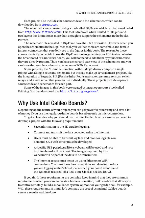
All the requirements for this imaginary project are attended by the Intel Galileo boards. If you want to connect to the Internet, you can use a simple Ethernet cable. If you need WiFi you can buy a mini-PCIe Intel Centrino N135 WiFi card, mPCIe card bracket, and antennas. Table 1-1 shows the average costs of these items.
Table 1-1. Mini-PCIe WiFi Card and Accessories
Description Cost in U.S. Dollars(*)
Intel Centrino WiFi N135 $8.00
mPCIe card brackets $5.00
Antennas with connectors $7.00
Intel Galileo $55.70
* Cost based on the average price on 3/18/2014 from several sites in the United States.
If you decide to use an Ethernet connection, the only cost is the Intel Galileo board. Otherwise, if you decide you need a WiFi connection, you have an additional of $20.00 to the Intel Galileo board, for a total of $75.70.
Now, suppose you want to compare the total cost of your project if you have an Arduino Uno and decide to buy some shields to meet the project’s requirements.
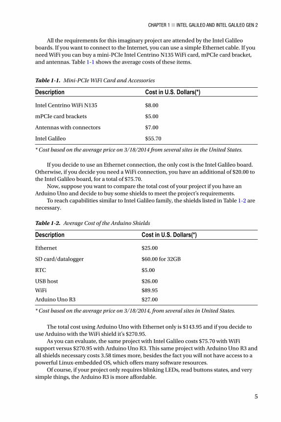
To reach capabilities similar to Intel Galileo family, the shields listed in Table 1-2 are necessary.
Table 1-2. Average Cost of the Arduino Shields
Description Cost in U.S. Dollars(*)
Ethernet $25.00
SD card/datalogger $60.00 for 32GB
RTC $5.00
USB host
WiFi
Arduino Uno R3
$26.00
$89.95
$27.00
* Cost based on the average price on 3/18/2014, from several sites in United States.
The total cost using Arduino Uno with Ethernet only is $143.95 and if you decide to use Arduino with the WiFi shield it’s $270.95.
As you can evaluate, the same project with Intel Galileo costs $75.70 with WiFi support versus $270.95 with Arduino Uno R3. This same project with Arduino Uno R3 and all shields necessary costs 3.58 times more, besides the fact you will not have access to a powerful Linux-embedded OS, which offers many software resources.
Of course, if your project only requires blinking LEDs, read buttons states, and very simple things, the Arduino R3 is more affordable.

Chapter 1 ■ Intel GalIleo and Intel GalIleo Gen 2
6
Hardware OverviewIntel Galileo Gen 2 was created to improve on some of the limitations of Intel Galileo. These details will be explained in the following sections, with an overview on the Quark SoC X1000 processor, Intel Galileo, and Intel Galileo Gen 2 boards.
The Processor: Intel Quark SoC X1000 Intel Quark SoC X1000 is a 32-bit processor designed for lower power consumption. It’s x86 compatible with Pentium opcode instructions but implements features like ACPI (Advanced Configuration and Power Interface) and includes several interfaces that provide connections with external peripherals. Intel Quark competes directly with ARM A and M class-based products and is the first Intel initiative to merge into the “Internet of Things” (IoT) and the wearable market.
Intel Quark SoC X1000 is code-named Clanton and is shown in Figure 1-2.
Figure 1-2. The Quark SoC X1000
Although the package is only 15x15mm, this tiny processor also offers an interface that allows you to connect to several peripherals, including Bluetooth devices, ZigBee, SD/SDIO/eMMC cards, I2C devices, and USB2 host and device ports. It also handles GPIOs interruptible or not by settings, supports temperature ranges that reach industrial, medical, and military applications (not to mention an internal programmable thermal sensor), and can run unmodified Linux kernel v3.8+. Figure 1-3 shows the peripherals supported by Intel Quark SoC.

Chapter 1 ■ Intel GalIleo and Intel GalIleo Gen 2
7
The following list contains more details regarding the processor:
Processor Core
Single Quark CPU core, single thread, 32 bits X86, at 400MHz•
Processor UnCore
DDR3 memory controller up to 2GB at 800MTS and ECC-On-Chip•
Embedded 512KB RAM and 16KB cache•
Supports legacy blocks: PC Compatible: IO ports, PCI, ACPI, and •so on
Low-cost 10-pin JTAG•
I/O Specifications
Two 10/100MB Ethernet MACs•
Two USB2 host ports (EHCI and OHCI)•
Two HS UART controllers•
One SPI port for peripherals•
One USB2 HS device port•
One SD/SDIO/EMMC interface•
One I2C/GPIO controller•
Sixteen GPIOs with programmable interrupts (edge) •
Figure 1-3. Peripheral support of Intel Quark SoC X1000
Chapter 1 ■ Intel GalIleo and Intel GalIleo Gen 2
8
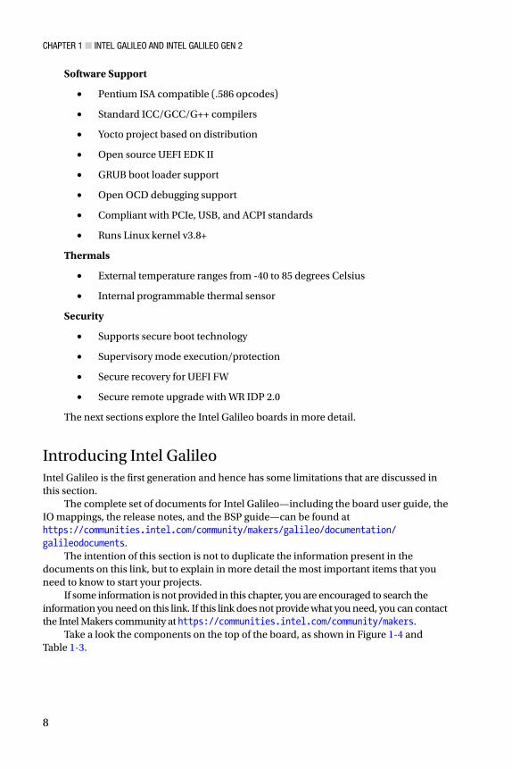
Software Support
Pentium ISA compatible (.586 opcodes)•
Standard ICC/GCC/G++ compilers•
Yocto project based on distribution•
Open source UEFI EDK II•
GRUB boot loader support•
Open OCD debugging support•
Compliant with PCIe, USB, and ACPI standards•
Runs Linux kernel v3.8+•
Thermals
External temperature ranges from -40 to 85 degrees Celsius•
Internal programmable thermal sensor•
Security
Supports secure boot technology•
Supervisory mode execution/protection•
Secure recovery for UEFI FW•
Secure remote upgrade with WR IDP 2.0•
The next sections explore the Intel Galileo boards in more detail.
Introducing Intel GalileoIntel Galileo is the first generation and hence has some limitations that are discussed in this section.
The complete set of documents for Intel Galileo—including the board user guide, the IO mappings, the release notes, and the BSP guide—can be found at https://communities.intel.com/community/makers/galileo/documentation/galileodocuments.
The intention of this section is not to duplicate the information present in the documents on this link, but to explain in more detail the most important items that you need to know to start your projects.
If some information is not provided in this chapter, you are encouraged to search the information you need on this link. If this link does not provide what you need, you can contact the Intel Makers community at https://communities.intel.com/community/makers.
Take a look the components on the top of the board, as shown in Figure 1-4 and Table 1-3.
Chapter 1 ■ Intel GalIleo and Intel GalIleo Gen 2
9
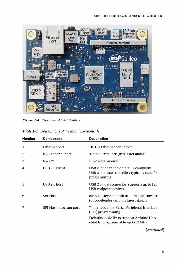
Figure 1-4. Top view of Intel Galileo
Table 1-3. Descriptions of the Main Components
Number Component Description
1 Ethernet port 10/100 Ethernet connector
2 RS-232 serial port 3-pin 3.5mm jack (this is not audio)
3 RS-232 RS-232 transceiver
4 USB 2.0 client USB client connector: a fully compliant USB 2.0 device controller; typically used for programming
5 USB 2.0 host USB 2.0 host connector; supports up to 128 USB endpoint devices
6 SPI Flash 8MB Legacy SPI Flash to store the firmware (or bootloader) and the latest sketch
7 SPI Flash program port 7-pin header for Serial Peripheral Interface (SPI) programming
Defaults to 4MHz to support Arduino Uno shields; programmable up to 25MHz
(continued)
Chapter 1 ■ Intel GalIleo and Intel GalIleo Gen 2
10
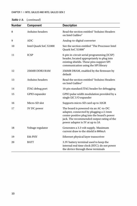
Table 1-3. (continued)
Number Component Description
8 Arduino headers Read the section entitled “Arduino Headers on Intel Galileo”
9 ADC Analog-to-digital converter
10 Intel Quark SoC X1000 See the section entitled “The Processor Intel Quark SoC X1000”
11 ICSP 6-pin in-circuit serial programming (ICSP) header, located appropriately to plug into existing shields. These pins support SPI communication using the SPI library
12 256MB DDR3 RAM 256MB DRAM, enabled by the firmware by default
13 Arduino headers Read the section entitled “Arduino Headers on Intel Galileo”
14 JTAG debug port 10-pin standard JTAG header for debugging
15 GPIO expander GPIO pulse width modulation provided by a single I2C I/O expander
16 Micro-SD slot Supports micro-SD card up to 32GB
17 5V DC power The board is powered via an AC-to-DC adapter, connected by plugging a 2.1mm center-positive plug into the board’s power jack. The recommended output rating of the power adapter is 5V at up to 3A
18 Voltage regulator Generates a 3.3 volt supply. Maximum current draw to the shield is 800mA
19 Eth PHY Ethernet physical layer transceiver
20 BATT 3.3V battery terminal used to keep the internal real time clock (RTC); do not power the device through these terminals
Chapter 1 ■ Intel GalIleo and Intel GalIleo Gen 2
11
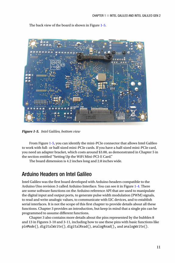
From Figure 1-5, you can identify the mini-PCIe connector that allows Intel Galileo to work with full- or half-sized mini-PCIe cards. If you have a half-sized mini-PCIe card, you need an adapter bracket, which costs around $3.00, as demonstrated in Chapter 5 in the section entitled “Setting Up the WiFi Mini-PCI-E Card.”
The board dimension is 4.2 inches long and 2.8 inches wide.
Arduino Headers on Intel GalileoIntel Galileo was the first board developed with Arduino headers compatible to the Arduino Uno revision 3 called Arduino Interface. You can see it in Figure 1-4. There are some software functions on the Arduino reference API that are used to manipulate the digital input and output ports, to generate pulse width modulation (PWM) signals, to read and write analogic values, to communicate with I2C devices, and to establish serial interfaces. It is not the scope of this first chapter to provide details about all these functions. Chapter 3 provides an introduction, but keep in mind that a single pin can be programmed to assume different functions.
Chapter 3 also contains more details about the pins represented by the bubbles 8 and 13 in Figures 3-10 and 3-11, including how to use these pins with basic functions like pinMode(), digitalWrite(), digitalRead(), analogRead(), and analogWrite().
Figure 1-5. Intel Galileo, bottom view
The back view of the board is shown in Figure 1-5.

Chapter 1 ■ Intel GalIleo and Intel GalIleo Gen 2
12
Fourteen Digital Input/Output Pins (IO2 to IO13, TX, and RX)
Each of the 14 digital pins on Galileo can be used as an input or output. The pins operate at 3.3V or 5V DC. Each pin can source a maximum of 10mA or sink a maximum of 25mA and has an internal pull-up resistor (disconnected by default) of 5.6 to 10 KOhms.
Six digital pins can be used as PWM outputs; they are labeled with the tilde (~) symbol. The pins with this capability are 3, 5, 6, 9, 10, and 11.
The 0 and 1 pins can be programmed for the UART interface, such as RX and TX. When used as UART, the serial speed is programmable.
Pins 2 and 3 also can be programmed to be used as the UART interface. However, when they’re used as a serial interface, the Linux serial console will be lost.
There is a speed limitation on I/O ports. Due to the limitation of the sysfs implementation on Linux kernel v3.8 and the necessity of sending I2C commands to the Cypress IO expander, there is a delay of 2ms in the ports. This limits the frequency to a maximum of 230Hz when you set the ports as digital output. However, considering that pin header 2 and 3 are connected directly to SoC, it is possible to reach 477KHz to 2.93MHz, as described in Chapter 4 in the section entitled “How to Make Intel Galileo’s I/O Faster.”
I2C Bus Controlled by the SCL and SDA Pins
The I2C or two-wire interface (TWI) can be controlled by A4 or SDA pin and A5 or SCL pin. Within the Arduino context, the I2C might be programmed easily using the wire library demonstrated in Chapter 4.
An important observation regarding I2C is that Intel Galileo operates only as a master device and the internal I2C expander (Cypress IC) runs only in standard speed (100KHz).
AREF Is Unused
The AD729 A/D is used as internal reference for the analog ports. Thus, external reference voltage for the analog inputs is not supported and it is not possible to change the upper end of the analog input range using the AREF pin and the analogReference() function.
Analog Input Pins (A0-A5)
The six analog ports A0 to A5 have a resolution of 12 bits, which counts until 4096. By default, the analog ports measures from 0V (ground) to 5V.
Power Pins
This bulleted list describes the pins in same order of the headers, from right to left:
• IOREF: Some shields on the market work with 3.3V or 5V. In order to select the proper operation voltage level for the Intel Galileo, be sure to use the jumper tagged IOREF. Note that the jumper on the left selects 3.3V and the right operation remains set to 5V.
Chapter 1 ■ Intel GalIleo and Intel GalIleo Gen 2
13
• RESET button/pin: The pin or the Reset button are both used to reset the Arduino sketch, not the board.
• 3.3V output pin: Provides 3.3V generated by the on-board regulator with a maximum current drain to the shield of 800mA.
• 5V output pin: This pin outputs 5V from the 5V power supply or the USB connector. However, it is best to keep the power supply connected. Maximum current draw to the shield is 800mA.
• GND (2 pins): Only ground pins.
• VIN: Instead of using the external and regulated 5V power supply, you can supply voltage through this pin. However, if this pin is used, the power supply must also be regulated at 5V. Otherwise, it might damage the board.
Sink and Source Currents in Outputs
When the pins are set as output, the circuit can provide current (source) or the circuit can receive current (sink), depending on the device or circuit connected to the ports.
Some developers refer to the source current as the “positive” current and to the sink as the “negative” current.
Intel Galileo can be used as source or sink, but it is necessary to be aware of the port’s limitations when used as output.
Each individual pin can provide 10mA as source or 25mA as sink. Combined pins can have 40mA as source until 200mA but everything depends on how they are combined.
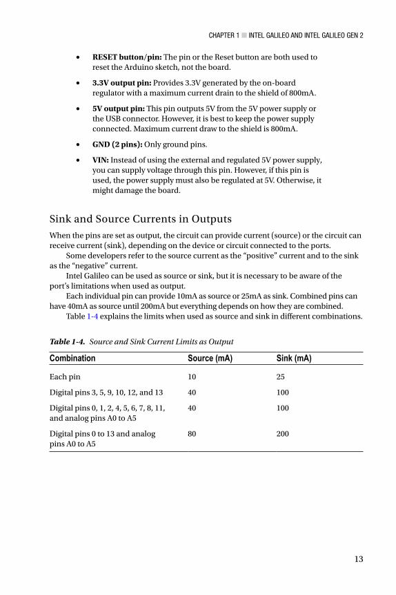
Table 1-4 explains the limits when used as source and sink in different combinations.
Table 1-4. Source and Sink Current Limits as Output
Combination Source (mA) Sink (mA)
Each pin 10 25
Digital pins 3, 5, 9, 10, 12, and 13 40 100
Digital pins 0, 1, 2, 4, 5, 6, 7, 8, 11, and analog pins A0 to A5
40 100
Digital pins 0 to 13 and analog pins A0 to A5
80 200
Chapter 1 ■ Intel GalIleo and Intel GalIleo Gen 2
14
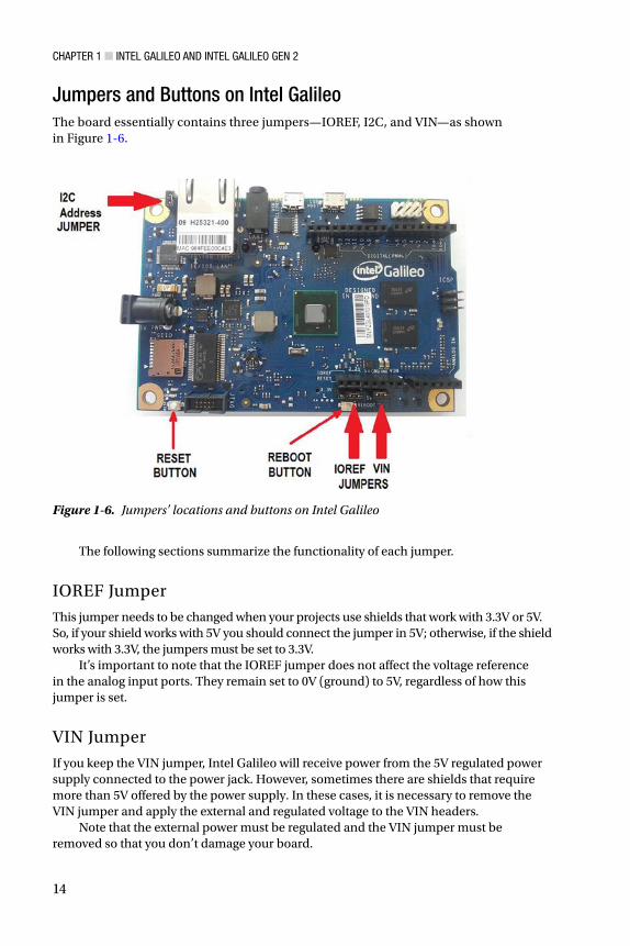
The following sections summarize the functionality of each jumper.
IOREF Jumper
This jumper needs to be changed when your projects use shields that work with 3.3V or 5V. So, if your shield works with 5V you should connect the jumper in 5V; otherwise, if the shield works with 3.3V, the jumpers must be set to 3.3V.
It’s important to note that the IOREF jumper does not affect the voltage reference in the analog input ports. They remain set to 0V (ground) to 5V, regardless of how this jumper is set.
VIN Jumper
If you keep the VIN jumper, Intel Galileo will receive power from the 5V regulated power supply connected to the power jack. However, sometimes there are shields that require more than 5V offered by the power supply. In these cases, it is necessary to remove the VIN jumper and apply the external and regulated voltage to the VIN headers.
Note that the external power must be regulated and the VIN jumper must be removed so that you don’t damage your board.
Figure 1-6. Jumpers’ locations and buttons on Intel Galileo
Jumpers and Buttons on Intel GalileoThe board essentially contains three jumpers—IOREF, I2C, and VIN—as shown in Figure 1-6.
Chapter 1 ■ Intel GalIleo and Intel GalIleo Gen 2
15
I2C Address Jumper
Considering it is possible to connect external I2C slaves as devices to Intel Galileo, this I2C address jumper was introduced in order to avoid address conflicts between these external devices and the internal I2C devices (the EEPROM and Cypress GPIO expander).
If you keep J2 connected to pin 1, the one marked with a little white triangle, the GPIO expander address will be 0100001 and the 7-bit EEPROM address will be 1010001. If you change the jumper position, the GPIO expander address will be 0100000 and the EEPROM address will be 1010000.
Reset Button
This button resets the currently running sketch, not Linux itself. You can manually kill the sketch process and execute it again.
Reboot Button
This button reboots the whole system, including Linux.
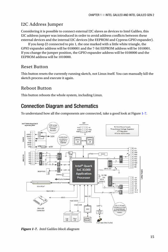
Connection Diagram and SchematicsTo understand how all the components are connected, take a good look at Figure 1-7.
Figure 1-7. Intel Galileo block diagram

Chapter 1 ■ Intel GalIleo and Intel GalIleo Gen 2
16
Explanations of Figure 1-7 are detailed here:
Although Intel Galileo provides a 3-pin 3.5mm jack, this not used •for audio and in fact causes confusion at first glance, because this jack is actually used for serial debugging, whereby you can open a Linux shell. Later in this chapter, you learn how to build your own cable and access the Linux shell.
All pins that support PWM have a tilde (~) in front of their tags. •For example, the pin IO3 has a tilde in front of its name, which means it supports PWM.
The multiplexers (MUX) represented in the diagram are used •because pins might assume different functions. For example, the pin IO11 might be used as digital input or output or to generate PWM. The MUX changes the connection of this pin to the appropriate circuit blocks responsible for each function.
Looking at the headers in Figure • 1-7, note that IO2 and IO3 are the only pins connected directly to Intel Quark. All the other IO pins are connected to the Cypress GPIO expander. This means that pins IO2 and IO3 are faster and are managed directly by the SoC. The other IO pins need to be managed through I2C commands sent to the Cypress GPIO expander, which means they take more time and reduce performance. Only pins IO2 and IO3 are interruptible (INT 0 and 1, respectively).
There are two micro-USB connectors that work as client and host •interfaces, a 10-pin JTAG connector, a mini-PCIe slot, two DDR3 memory chips of 256MB each, and an SPI interface connected directly to Intel Quark SoC.
The SD card slot uses an SDIO bus connected to Intel Quark and •supports an SD card until 32GB.
An interface allows you to update the firmware through the SPI •Flash protocol using a tool called SF100 DediProg. It’s explained in Chapter 2.
Although Intel Quark supports two Ethernet interfaces, only one •is exposed in a RJ45 Ethernet connector.
The analog headers are connected to an ADC that uses a high-•speed SPI interface.
The ICSP (In Circuit Serial Programming) interface is also •supported.
You’ll find the schematics for Intel Galileo in the schematics folder; the file is named Galileo Schematic.pdf. You can download it from https://communities.intel.com/docs/DOC-21822.
Chapter 1 ■ Intel GalIleo and Intel GalIleo Gen 2
17
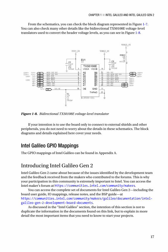
From the schematics, you can check the block diagram represented in Figure 1-7. You can also check many other details like the bidirectional TXS0108E voltage-level translators used to convert the header voltage levels, as you can see in Figure 1-8.
Figure 1-8. Bidirectional TXS0108E voltage-level translator
If your intention is to use the board only to connect to external shields and other peripherals, you do not need to worry about the details in these schematics. The block diagrams and details explained here cover your needs.
Intel Galileo GPIO MappingsThe GPIO mappings of Intel Galileo can be found in Appendix A.
Introducing Intel Galileo Gen 2Intel Galileo Gen 2 came about because of the issues identified by the development team and the feedback received from the makers who contributed to the forums. This is why your participation in this community is extremely important to Intel. You can access the Intel maker’s forum at https://communities.intel.com/community/makers.
You can access the complete set of documents for Intel Galileo Gen 2—including the board user guide, IO mappings, release notes, and the BSP guide—at https://communities.intel.com/community/makers/galileo/documentation/intel-galileo-gen-2-development-board-documents.
As discussed in the “Intel Galileo” section, the intention of this section is not to duplicate the information in the documents found on this link, but to explain in more detail the most important items that you need to know to start your projects.

Chapter 1 ■ Intel GalIleo and Intel GalIleo Gen 2
18
The Intel Quark X1000 SoC was preserved on Intel Galileo Gen 2 as the memory’s capacity. It also has the same clock frequency, the same analog and power headers (except for a small improvement in the digital header to allow redirection of UART1 to the pins IO2 and IO3), and the same I2C and SPI speeds. The next section discusses the new changes and improvements in detail.
In terms of Arduino headers, Intel Galileo Gen 2 provides the same set with major improvements, such as PWM. Figure 1-9 shows its major components.
Figure 1-9. Top view of Intel Galileo Gen 2
What’s New in Intel Galileo Gen 2Intel Galileo Gen 2 has some significant improvements over the first version. Some components have been removed as well. Consider the following:
The Cypress GPIO expander was removed and replaced with the •PCA 9535 to generate 12-bit PWM with precision. It’s not choppy as in Intel Galileo. So, when you create sketches using Servo API, you can move the servos with a precision of 1 degree.
With the removal of Cypress GPIO expander, the I2C address •jumper was also removed. Considering that most of the shields based on the I2C bus allow developers to change their addresses, the only possible conflict is with EEPROM, which still uses the address 0100001.

Chapter 1 ■ Intel GalIleo and Intel GalIleo Gen 2
19
Almost all IO headers are connected directly to Quark SoC, •which means the pins can achieve 2.97MHz. Chapter 4 discusses the new architecture and all its possible frequencies. With this new port speed, it’s possible to run shields and sensors that you couldn’t run using the old version.
The board supports the Power over Ethernet (PoE) module, which •wasn’t included in the board. It’s explained in Chapter 10.
The client USB connector is still a micro-USB connector but the •host USB has changed to a USB-OTG connector.
The power regulator now supports voltage between 7-15V DC.•
In addition to the IO0 and IO1 pins, which can be used for serial •communication as RX and TX respectively, pins IO2 and IO3 can also communicate serially as RX and TX, respectively. The problem with using IO2 and IO3 is that the Linux console is lost.
The MAX 3232 responsible for converting the RS-232 level to Intel •Quark SoC was also removed. Now it is necessary to use FTDI cables that are compatible with TTL-232 3.3 V
There is no VIN jumper anymore. The VIN is connected directed •to the DC jack, as you can see in Figure 1-10. You can check this in the schematics discussed in the section.
Figure 1-10. VIN connected directly to power jack DC
The board in general is a little bigger compared to Intel Galileo. •It is 4.87 inches long and 2.83 inches wide. The reason it’s bigger is because some internal voltage regulators on Intel Quark SoC are not being used anymore, and other external voltage regulators were added in order to keep Intel Quark SoC cooler.
Figure 1-11 shows the new form factor of Intel Galileo Gen 2 and the new location of some of the components. Note the buttons have moved and the IOREF jumper is in a totally different position. Note also the presence of the new OTG-USB connector, the FTDI terminals, and the capacitor of 47uF, which supports the PoE module.

Chapter 1 ■ Intel GalIleo and Intel GalIleo Gen 2
20
Figure 1-11. The top view of the Intel Galileo Gen 2
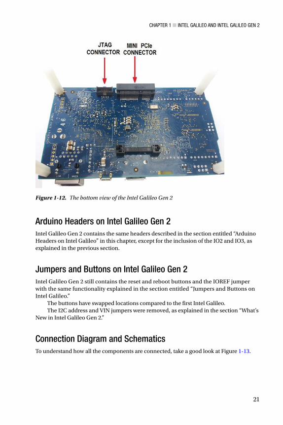
The Intel Galileo Gen 2 preserved the mini-PCIe connector on the bottom, as shown in Figure 1-12, but the 10-pin JTAG connector was also moved from the top to the bottom of the board.
Chapter 1 ■ Intel GalIleo and Intel GalIleo Gen 2
21
Arduino Headers on Intel Galileo Gen 2Intel Galileo Gen 2 contains the same headers described in the section entitled “Arduino Headers on Intel Galileo” in this chapter, except for the inclusion of the IO2 and IO3, as explained in the previous section.
Jumpers and Buttons on Intel Galileo Gen 2Intel Galileo Gen 2 still contains the reset and reboot buttons and the IOREF jumper with the same functionality explained in the section entitled “Jumpers and Buttons on Intel Galileo.”
The buttons have swapped locations compared to the first Intel Galileo.The I2C address and VIN jumpers were removed, as explained in the section “What’s
New in Intel Galileo Gen 2.”
Connection Diagram and SchematicsTo understand how all the components are connected, take a good look at Figure 1-13.
Figure 1-12. The bottom view of the Intel Galileo Gen 2

Chapter 1 ■ Intel GalIleo and Intel GalIleo Gen 2
22
Consider these issues when you’re looking at Figure 1-13:
Intel Galileo Gen 2 provides a terminal with six pins dedicated to •the FTDI cable connection in the TTL level of 3.3V. This terminal provides access to the Linux console. It replaces the previous serial audio jack present on Intel Galileo.
Like the first Intel Galileo, all pins that support PWM have a tilde •(~) in front of their tags. For example, the pin IO3 has a tilde in front of its name, which means it supports PWM.
The multiplexers (MUX) represented in the diagram are used •because the pins might assume different functions. For example, the pin IO11 might be used as digital input or output or to generate PWM, thus the MUX changes the connection of this pin to the appropriate circuit blocks responsible for each function.
The IO header is completely different compared to the first Intel •Galileo. Now, most IO pins are connected directly to Intel Quark SoC with the exception of IO7 and IO8, which are connected to the PCA GPIO expander. Consequently, all pins can achieve 2.97MHz except for pins IO7 and IO8, which will achieve the maximum of 1.8KHz (see Chapter 4 for more details). Note that pins IO2 and IO3 are the only ones that are interruptible
Figure 1-13. Intel Galileo Gen 2 block diagram

Chapter 1 ■ Intel GalIleo and Intel GalIleo Gen 2
23
(INT 0 and 1 respectively). Another reason for IO7 and IO8 to be connected to the GPIO expander is because among the 14 IO pins on Intel Quark, they are used to reset the mini-PCIe.
Note that pins IO2 and IO3 now can be used as serial consoles as •well—IO2 as RX and IO3 as TX. If these pins are used as serial, the Linux console through the FTDI cable is lost. Read Chapter 4 for more details.
The VIN and I2C address jumpers do not exist anymore.•
Many other elements haven’t changed from the first Intel Galileo, such as:
There are two micro-USB connectors that work as client and host •interfaces—a 10-pin JTAG connector, a mini-PCIe slot, two DDR3 memory chips of 256MB each, and a SPI interface connected directly to Intel Quark SoC.
The SD card slot uses a SDIO bus connected to Intel Quark and •supports the SD card until 32GB.
There is an interface that allows you to update the firmware •through SPI flash protocol using a tool called SF100 DediProg. It’s explained in Chapter 2.
Although Intel Quark supports two Ethernet interfaces only one is •exposed in a RJ45 Ethernet connector.
The analog headers are connected to an ADC that uses a high-speed •SPI interface.
The ICSP (In Circuit Serial Programming) interface is also supported.•
You can find the schematics for Intel Galileo Gen 2 in the schematics folder and the file is Galileo_Gen2_Schematic.pdf. You can also download them from https://communities.intel.com/docs/DOC-22895.
Intel Galileo Gen 2 GPIO MappingsThe GPIO mappings of Intel Galileo can be found in the Appendix B.
Preparing Your CablesTwo types of cables are used in this book:
• A high-speed USB 2.0 male-to-micro USB cable, commonly called a USB data cable: This cable is used to download, debug, and run sketches via Intel Arduino IDE. This cable is essential; without it, you will not be able to run any of the projects in this book. You can use the same cable on both Intel Galileo and Intel Galileo Gen 2. Figure 1-14 shows this cable. The cost varies between $3.00 and $6.00, depending on the quality of the cable you order.

Chapter 1 ■ Intel GalIleo and Intel GalIleo Gen 2
24
• A 3.3V FTDI cable if you have an Intel Galileo Gen 2 or a serial cable with a stereo jack if you have the first Intel Galileo: As explained, Intel Galileo and Intel Galileo Gen 2 run embedded Linux 3.8 on the official releases. You’ll want to access the Linux console for kernel debugging, to install native applications, to write Python programs, and so on. Some chapter of this book utilizes this cable so it is recommended you have it. The details surrounding these cables are discussed in the sections entitled “The Serial Cable for Intel Galileo” and “The Serial Cable for Intel Galileo Gen 2” in this chapter.
There is some confusion between the Arduino serial console, the Arduino serial, and the Arduino debug terminal. All of these terms are commonly used in the community and refer to the debug terminal provided by the Arduino IDE. In other words, this is the first high-speed USB 2.0 A male-to-micro USB cable mentioned earlier.
The next section explains the serial cables you’ll need in order to access the Linux console after your connection has more than one cable.
The Serial Cable for Intel GalileoThis section is related to the Linux console. In other words, it assumes you have access to a Linux terminal and can run regular Linux commands directly on your board. In this case, you’ll use a serial cable with an audio jack adaptor.
This section also explains how to access the serial cable. Gaining access using WiFi and Ethernet via SSH is explained in Chapter 5.
If your computer contains a RS-232 port, you simply need a serial cable DB9 male connected to a 3.5mm jack, which costs around $4. If your computer only supports USB, you need a second cable converter with a RS-232 male connector to USB, which costs around $9.
Table 1-5 lists the cables and the recommended part numbers.
Table 1-5. Cables for Serial Debugging on Intel Galileo
Number Description
1 Cable with a DB9 male connector to a 3.5mm jack
1 Cable converter RS-232 female connector-to-micro USB 2.0 (only if your computer does not have RS-232 connector)
The DB9 male with stereo 3.5mm jack is shown in Figure 1-14 and the converter RS-232 female connector-to-micro USB 2.0 is shown in Figure 1-15.

Chapter 1 ■ Intel GalIleo and Intel GalIleo Gen 2
25
Figure 1-15. Cable converter RS-232 female connector-to-micro USB 2.0
If your computer does not have the RS-232 port, you can also use a single cable converter with a 3.5mm stereo jack connected to a micro-USB FTDI cable. This cable costs around $17, but if you order a cable converter RS-232 female connector to micro-USB and a simple standard stereo audio jack connector (about $1.00), you can build your own cable with a final cost of $10.
To build your own cable based on a RS-232 to micro-USB converter, remove the female DB9 connector and replace it with the stereo jack 3.5mm. Follow the connections shown in Figure 1-16 to do this.
Figure 1-14. Cable with a DB9 male connector to a 3.5mm jack

Chapter 1 ■ Intel GalIleo and Intel GalIleo Gen 2
26
Note the stereo jack has three contact points—the tip that must be the TX signal is connected to pin 2, the ring that must be the RX signal is connected to pin 3, and the sleeve that must be the ground is connected to pin 5. Optionally, considering the serial communication with Intel Galileo does not require handshaking and parity control, pin 7 (CTS) and pin 8 (RTS) might be used instead as pin 4 (DSR) to pin 6 (DTR).
The next step is to test your cable and access the Linux console.
The Serial Cable for Intel Galileo Gen 2If you have an Intel Galileo Gen 2, you need a FTDI cable with a 6-pin connector and TTL level of 3.3V IO (serial) to USB.
This cable is necessary because the MAX 3232 on Intel Galileo was removed in Intel Galileo Gen 2, so there is no built-in circuit to convert the TTL levels. On the other hand, the cost was reduced with the removal of this audio jack.
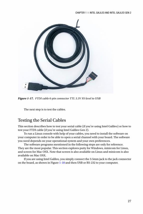
The cable I recommend is sold by SparkFun; see https://www.sparkfun.com/products/9717. It costs $17.95. The cable is shown in Figure 1-17.
Figure 1-16. Scheme to build your own 3.5mm stereo serial jack cable
Chapter 1 ■ Intel GalIleo and Intel GalIleo Gen 2
27
Figure 1-17. FTDI cable 6-pin connector TTL 3.3V IO level to USB
The next step is to test the cables.
Testing the Serial CablesThis section describes how to test your serial cable (if you’re using Intel Galileo) or how to test your FTDI cable (if you’re using Intel Galileo Gen 2).
To run a Linux console with help of your cables, you need to install the software on your computer in order to be able to open a serial channel with your board. The software you need depends on your operational system and your own preferences.
The software programs mentioned in the following steps are only for reference. They are the most popular. This section explores putty for Windows, minicom for Linux, and screen for Mac OSX. Note that screen is also available on Linux and minicom is also available on Mac OSX.
If you are using Intel Galileo, you simply connect the 3.5mm jack to the jack connector on the board, as shown in Figure 1-18 and then USB or RS-232 to your computer.

Chapter 1 ■ Intel GalIleo and Intel GalIleo Gen 2
28
Figure 1-19. Connecting the FTDI cable to Intel Galileo Gen 2
Figure 1-18. Connecting a 3.5mm serial jack cable to Intel Galileo
If your board is Intel Galileo Gen 2, make sure the inline connector connects pin 1 (usually black) to pin 1 of the FTDI connector on the board. This is represented by a little white triangle shown in Figure 1-19. You’ll connect the other end of the cable to your computer.

Chapter 1 ■ Intel GalIleo and Intel GalIleo Gen 2
29
WindowsThe following steps explain how to set up the Linux console on Windows:
1. After you insert the cable, wait for a few seconds so that the USB is enumerated. Then open the Windows Device Manager by choosing Start ➤ Control Panel ➤ Hardware and Sound ➤ Device Manager. You can also press the Windows key and “R” at same time, and then type devmgmt.msc.
2. In the Device Manager, check the COM port available under the Ports section. Figure 1-20 shows an example of a COM port enumerated as COM5.
Figure 1-20. Intel Galileo COM port on Windows
3. Download putty and install it on your Windows machine. You can download it from http://www.chiark.greenend.org.uk/~sgtatham/putty/download.html.
4. Execute putty. Select the Serial protocol and enter the COM port number. Then click the Open button, as shown in Figure 1-21.

Chapter 1 ■ Intel GalIleo and Intel GalIleo Gen 2
30
5. Finally, to access the Linux console, you type username root and press Enter. You will then have access to the Linux console, as shown in Figure 1-22.
Figure 1-21. Configuring putty to open the Linux console
Figure 1-22. The Linux serial console

Chapter 1 ■ Intel GalIleo and Intel GalIleo Gen 2
31
Ubuntu LinuxThe procedure to set up Intel Galileo’s Linux console on a Linux computer is easy. As mentioned, serial communication on Linux computers is based on the minicom software.
The following steps are necessary to get the Linux console working:
1. After you insert the cable, wait for a few seconds for the USB to be enumerated.
2. Open a Linux terminal. You can press Ctrl+T to do this.
3. Check the port by typing the command dmesg|grep tty. For example, Figure 1-23 shows the port enumerated as ttyUSB0.
Figure 1-23. Checking the USB port enumerated on the Ubuntu terminal
4. Finally, to access the Linux console, you typing the sudo minicom --device /dev/ttyUSB0 command. The terminal will open. You need to use the username root.
Mac OSXThe following steps describe how to set up the Linux console on Mac OSX.
1. After you insert the cable, wait for a few seconds so that the USB is enumerated.
2. Open an OSX terminal. You can press z and the spacebar at same time to open the Spotlight text box. Then type terminal and press Enter.
3. In the terminal, check what is the serial port enumerated as following command:
~$ ls /dev/tty.usb*/dev/tty.usbserial-A603HVUT
Chapter 1 ■ Intel GalIleo and Intel GalIleo Gen 2
32
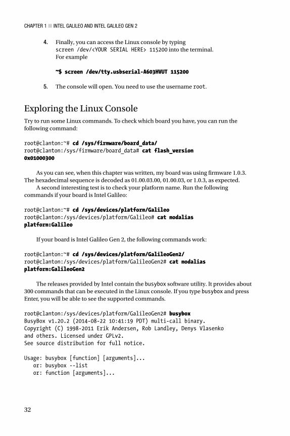
4. Finally, you can access the Linux console by typing screen /dev/<YOUR SERIAL HERE> 115200 into the terminal. For example ~$ screen /dev/tty.usbserial-A603HVUT 115200
5. The console will open. You need to use the username root.
Exploring the Linux ConsoleTry to run some Linux commands. To check which board you have, you can run the following command: root@clanton:~# cd /sys/firmware/board_data/root@clanton:/sys/firmware/board_data# cat flash_version0x01000300
As you can see, when this chapter was written, my board was using firmware 1.0.3. The hexadecimal sequence is decoded as 01.00.03.00, 01.00.03, or 1.0.3, as expected.
A second interesting test is to check your platform name. Run the following commands if your board is Intel Galileo: root@clanton:~# cd /sys/devices/platform/Galileoroot@clanton:/sys/devices/platform/Galileo# cat modaliasplatform:Galileo
If your board is Intel Galileo Gen 2, the following commands work: root@clanton:~# cd /sys/devices/platform/GalileoGen2/root@clanton:/sys/devices/platform/GalileoGen2# cat modaliasplatform:GalileoGen2
The releases provided by Intel contain the busybox software utility. It provides about 300 commands that can be executed in the Linux console. If you type busybox and press Enter, you will be able to see the supported commands. root@clanton:/sys/devices/platform/GalileoGen2# busyboxBusyBox v1.20.2 (2014-08-22 10:41:19 PDT) multi-call binary.Copyright (C) 1998-2011 Erik Andersen, Rob Landley, Denys Vlasenkoand others. Licensed under GPLv2.See source distribution for full notice. Usage: busybox [function] [arguments]... or: busybox --list or: function [arguments]...
Chapter 1 ■ Intel GalIleo and Intel GalIleo Gen 2
33
BusyBox is a multi-call binary that combines many common Unix utilities into a single executable. Most people will create a link to busybox for each function they wish to use and BusyBox will act like whatever it was invoked as. Currently defined functions: [, [[, acpid, ar, arp, arping, ash, awk, basename, blkid, blockdev, bootchartd, brctl, bunzip2, bzcat, cat, chgrp, chmod, chown, chroot, chrt, clear, cmp, cp, cpio, cttyhack, cut, date, dc, dd, deallocvt, depmod, df, diff, dirname, dmesg, dnsdomainname, du, dumpkmap, echo, egrep, env, expr, false, fdisk, fgrep, find, findfs, flock, free, fsck, fsync, ftpd, ftpget, ftpput, fuser, getty, grep, gunzip, gzip, halt, hd, head, hexdump, hostname, hwclock, id, ifconfig, ifdown, ifup, insmod, ionice, iostat, ip, kill, killall, klogd, less, ln, loadkmap, logger, login, logname, logread, losetup, ls, lsmod, lsof, lspci, lsusb, md5sum, mdev, mkdir, mkfifo, mknod, mktemp, modprobe, more, mount, mv, nc, netstat, nice, nohup, nslookup, od, patch, pidof, ping, ping6, pivot_root, pmap, poweroff, printf, ps, pwd, rdate, readlink, realpath, reboot, renice, reset, resize, rm, rmdir, rmmod, route, run-parts, sed, seq, setconsole, setserial, setsid, sh, sleep, sort, start-stop-daemon, stat, strings, stty, sulogin, switch_root, sync, sysctl, syslogd, tail, tar, tcpsvd, tee, telnet, telnetd, test, tftp, time, timeout, top, touch, tr, traceroute, traceroute6, true, tty, udhcpc, umount, uname, uniq, unzip, uptime, usleep, vconfig, vi, watch, wc, wget, which, who, whoami, xargs, yes, zcat, zcip
If you need to execute one of these commands, you simply type the desired command.
Testing the Data CablesThe high-speed USB 2.0 male-to-micro USB cable, or simply the data cable, is used to transfer and debug the sketches. Testing this cable is covered in Chapter 3 because doing so requires the installation of the IDE.
SummaryThis first chapter introduced the importance of the maker community and Intel’s commitment to them with Intel Quark X1000 SoC.
You were also introduced to the Intel Galileo boards. You learned about the hardware architecture, the software features, and the advantages of these boards and how powerful they are.
This chapter is more descriptive than practical, but that’s not the case for the rest of this book. Enjoy!

![Tester av Raspberry Pi 3 och Intel Galileo Gen 2uu.diva-portal.org/smash/get/diva2:962973/FULLTEXT01.pdf · 2016-09-07 · Intel Galileo Gen 2 [Int16c]. Motivationen till detta har](https://static.fdocuments.in/doc/165x107/5f08e0b47e708231d4242891/tester-av-raspberry-pi-3-och-intel-galileo-gen-2uudiva-962973fulltext01pdf.jpg)