
Integrity Service Excellence AFSC Reverse Engineering Overview Edward Ayer Technical Director...
18
Integrity Service Excellence AFSC Reverse Engineering Overview Edward Ayer Technical Director AFSC/EN DSN 336-3528 Distribution A: Approved for Public Release
-
Upload
adela-bailey -
Category
Documents
-
view
213 -
download
0
Transcript of Integrity Service Excellence AFSC Reverse Engineering Overview Edward Ayer Technical Director...

Integrity Service Excellence
AFSC Reverse Engineering
Overview
Edward AyerTechnical DirectorAFSC/ENDSN 336-3528
Distribution A: Approved for Public Release

Reverse Engineering And Critical Tooling
Mission Statement
Support the warfighter by rapidly solving real world part and tooling supportability issues using state-of-the-art reverse engineering tools and manufacturing technologies to improve technical data availability
and depot maintenance performance
Reverse Engineering
• Dimensional Inspection
• CAD generation from sample part
Process Improvement• Validation of
Tooling• Alternative Tooling
Options• Root Cause
Analysis
Additive Manufacturing• Rapid Prototyping• CAD Model
Verification• Form Blocks• Fixture
Components• Bond Forms• Non-Flight Critical
Components
2

The Reverse Engineering
Process
Form
Fit
Function
Metallurgical Analysis
Geometrical/Dimensional
Analysis
Operating Environment –
Functional Understanding
Material Characteristics
& Processes
CAD Models/Drawings
Dimensional Verification Report
Design ModificationsStress Analysis
3D-Printed Rapid Prototype
Technical Data Package (TDP)
Reverse Engineering Process Customer Requirements Outputs
Reverse Engineering
3

Reverse EngineeringArt of the Possible Process
Project Planni
ng
Data Generation
Preliminary
Design
Critical Design
Testing
Val/Ver
Closeout
Procurement Manufacturing
Tech Data
Reverse Engineering uses the Gated Process shown below with an extensive Critical Path associated with each gate and specified Exit Criteria to manage projects through the process.
The additional supplemental gates shown below are occupied by technicians, tech writers, draftsman, and a program manager to enable engineers to focus on their design activities within the primary gates.
Project Planning
•Folders setup and populated•Phase Checklist, Page 2•TSDD (not updated this phase)•Signed Form 20 for POs•TO number requested
Data Generation
•DMS Study•Block Diagram(s)•Wiring Diagram•BOM
Preliminary Design
•TSDD Chpt 5-6, Appxs A-D, Appx F, Col A-C
•Updated TSDD Chapters 1-3
•Top Level Steps for UUT Test
•Purchasing Spreadsheet
•Detailed Technical Requirements of Equip
•Detailed Test Plan
Critical Design
•TSDD Appendix E•Updated Purchasing Spreadsheet•Source Code & Executable•Go run printout•List of Drawings for PO/TO•Detailed Test and Repair Steps•Final List of Tools Equipment Consumables
Testing
•Updated Source Code
•Updated Executables
•Go run printout•Code defects documented
•TSDD Appendix F (Columns D-G)
Val/Ver
•TSDD Appx F, Col. G of Sheet 1, Sheet 2•Updated Test and Repair Process•Signed CSCI form•SVD•CPIN to ES•Functional Tester on Line•Customer/QA Approved Process
Closeout
•Signed Customer Closeout Form
•Lessons Learned Report
•Final Documents compiled
A sampling of the exit criteria is shown below. The exit criteria are documented in the Standard Work for the process.
4

Software Technologies
Software• SolidWorks/Inventor
• used to design parts, fixtures, and form blocks• Metrolog/Spatial Analyzer (Metrology)
• used to run all metrology equipment• Rapidform (Reverse Engineering)
• used to turn scanned point clouds into solid models• DynaForm (Simulation)
• used to run simulations for sheet metal forming to mitigate material and shop time waste.
5

Measurement Technologies
• Leica and API 3D Laser Tracker/Scanner• laser light provides very accurate dimensional
measurement of single points, or point clouds• hand scanner allows for non-contact
measurement and point cloud acquisition for large and small parts
• hand probe allows for more accurate contact measurement with part
• Nikon Laser Radar Measuring• laser light travels to and from the target through a
reference path of calibrated optical fiber in an environmentally controlled module
• provides automated, non-contact measurement capability for large-volume applications of up to 50 meter radius
• ATOS Structured Light Imaging• Projected bi-dimensional patterns of non-
coherent light used to obtain dimensional information 6

Geometric Analysis Process
Many items have incomplete or missing technical data
Leveraging the geometric analysis processwe can capture an existing item by scanning and transforming it into a 3D CAD model
Benefits1. Reconstruction of a part2. Capture critical dimensions & surfaces3. Creation of tooling and fixtures4. Manufacture of a new item with either
traditional methods or direct digital manufacturing
Point Cloud Data
Subject Part of Interest
3D Scanning
Polygon NURBS
Surface/Solid Modeling
CAD Modeling 7

Mechanical Reverse Engineering
• Reverse engineering efforts currently involve– Mechanical engineers– Machine programming technicians – Industrial Engineering technicians
• AM Processes• AM Projects
– Welding fixtures– Tooling redesign– Mold Injection– Form Fit repairs– Rapid Prototyping for Die design– MFG broken/worn components for facility equipment
8
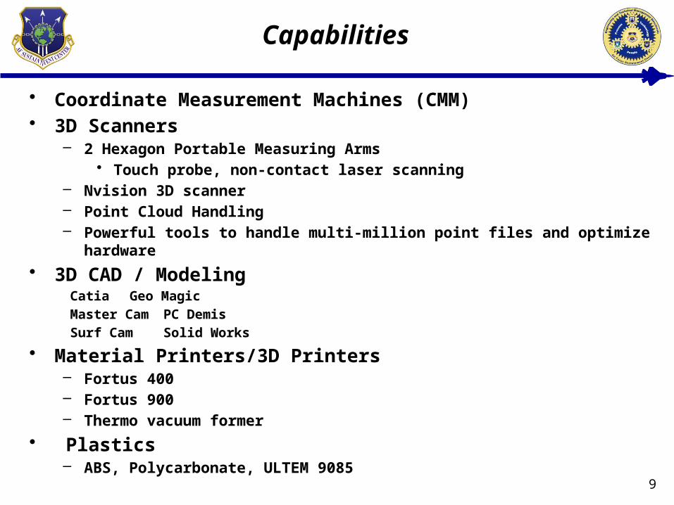
Capabilities
• Coordinate Measurement Machines (CMM)• 3D Scanners
– 2 Hexagon Portable Measuring Arms• Touch probe, non-contact laser scanning
– Nvision 3D scanner– Point Cloud Handling – Powerful tools to handle multi-million point files and optimize hardware
• 3D CAD / Modeling Catia Geo Magic
Master Cam PC Demis
Surf Cam Solid Works
• Material Printers/3D Printers– Fortus 400– Fortus 900– Thermo vacuum former
• Plastics – ABS, Polycarbonate, ULTEM 9085
9

ALC AM Materials Uses Equipment
Warner Robins AFB Extruded ABS, PLA, Ultem, Nylon, Powder bed Gypsum
Fixtures, tooling, adapters, spacers, guides, machine covers, sheet metal forming, fit checks for CNC code
Stratasys3D Systems
Hill AFB Extruded ABS, PLA, Ultem, Nylon,Powder bed Gypsum
Functional prototypes, fit checks, molds, jigs, fixtures, plugs, shop equipment, special tools, educational & concept models, blast masking, conforming anodes, tubing, minor industrial ducting, scan to CAD to print
Stratasys3D Systems
Tinker AFB Extruded ABS, PLA, Ultem, Nylon,Powder bed Gypsum
Fixtures, forming blocks, tooling, interface cable backshells, gaskets, fit & form, prototyping, couplings, spacers, guides, blast masking, paint masking, plating masking
Stratasys3D Systems
• Similar Additive Manufacturing equipment exists at the different ALCs with similar capabilities
• ALCs working to purchase additional industrial type printing machines for the near future.
Additive Technologies
10

Organization Software Tools 3-D Measurement
Systems
Dedicated P.E.s
402 EMXG Solid Works, AutoDesk Inventor, AutoCAD
None 1 Full Time
402 CMXG PCDMIS, Geomagic, NX, CMM, Optical Comparator,
3 Full Time
402 SMXG Solid Works, AutoDesk Inventor
New Development, Not
R.E.
2 Full Time
402 MXSG AutoCAD, AutoDesk Inventor
CMM 3 Part Time
11
Reverse Engineering Across AFSC
Organization Software Tools 3-D Measurement
Systems
Dedicated P.E.s
76thCMXGMetrolog, AutoDesk
Inventor, Rapid Form, Solid Works
Leica Laser Scanner
3 Full Time
76th SMXG Autodesk Inventor None Project Dependent
Organization Software Tools 3-D Measurement
Systems
Dedicated P.E.s
309th MXSG Solid Works, Verisurf 3 CMM, Optical Comparators,
Laser Scanners
5 Full Time
309th CMXG Solid Works, Polyworks, NX
Laser Tracker, Laser Scanner
2 Part Time
309th SMXG AutoDesk Inventor, AutoCAD
New Development, Not
R.E.
2 Full Time

12
AM Printing Capabilities Across AFSC
Organization Model Envelope(in) Material Type
76th CMXG 3DSystems Projet 860 20x15x9 VisiJet PXL
76th PMXG Stratasys Dimension Elite 8x8x12 ABS Plastic
76th SMXG iDeator12 12x12x12 ABS & PLA
76th SMXG Makergear M2 8x10x8 ABS & PLA
848 SCMG Stratasys Dimension SST 768
8x8x12 ABS
Organization Model Envelope(in) Material Type
516th SMXG Stratasys uPrint 8x6x6 ABS Plastic
516th SMXG Stratasys Mojo 5x5x5 ABS Plastic
309th CMXG 3DSystems Projet XXX Plastic
309th MXSG Stratasys Fortus 900 36x24x36 ABS ,Ultem,DR-100,ABS-ESD,PC
Organization Model Envelope(in) Material Type
402 CMXG Stratasys Fortus 400 mc 14x10x10 ABS ,Ultem,DR-100,ABS-ESD,PC
402 CMXG Stratasys Fortus 900 mcFY-16 Programming
36x24x36 ABS ,Ultem,DR-100,ABS-ESD,PC
402 MXSG MakerBot Replicator 2X 11x6x6 ABS Plastic
402 MXSG Stratasys Fortus 380 mc
16x14x16 ABS-M30, PC-ABS, PC, Nylon
12

Rapid Manufacturing
• Rapid Manufacturing Strategy Examples
Thermoform Mold• F-15 Glare Shield• SPO engineer design• Printed model -handworked first mold• Laser Scanned finished mold into 3D
model• Printed Mold- 2 pieces• Mold now produces finished part • Savings
• 3D vs Material and Man hours• $10K cost avoided
F-15 Sill Plate• Difficulties with MFG from drawing• Created model from drawing• Form fit part to F-15• Corrected CAD model before
production • Savings
• Material and Production time• $5.5K cost avoided
13

Reverse Engineering Samples
• Materials– Plastics, Polyform, composites, lexan
polycarbonite• Molds, F-15 glare shields, Bulkhead
repairs
• Process– Use of models, samples, drawings to
gather customer requirements and feedback
– 3D scanning to confirm accuracy of a design – Form, Fit, Function, model comparison
– Dimensional verification of all mfg parts for Quality and ISO compliance
– Tool-less fabrication of low volume production parts 14

Core CapabilitiesWe are able to create repair capability on both analog and digital circuits as well as certain field programmable gate arrays. We create efficient processes and procedures, develop more efficient repair processes, develop missing technical data, resolve surges, MICAPs, and backorders, reduce cost and increase reliability, and support depot repair line standup. We utilize the following platforms to conduct our analysis and develop technical data.
Huntron• Comparative component and net testing for fault isolation• Rapid turn time for diagnostic & repair
PinPoint II• Component functional test without schematic; creates schematic drawing• Card edge connector functional test
PXI• Compatible with 600+ different modules for analog, digital, and RF electronic test
and measurement applications• Powerful software with specialized timing and synchronization capabilities
Avionics Reverse EngineeringCapabilities
15

Reverse EngineeringSnapshot of Current Work
ALQ-213 CMSP/CMSC
C-5 CED
Complete redesign of aircraft part Environmental compliance testing as well as
functionality testing will be completed on the design
Project complete through prototype testing. Project currently in the military specification build process for operational and environmental testing
BRAT RFIU/SPD
Conducting extensive DMSMS study on both components of the BRAT to determine where redesign needs to occur
Producing technical data necessary to procure and repair components within RFIU and SPD
Follow-on effort will be to conduct any redesign activities required as discovered by our study
Developing organic repair capability for both LRUs (approximately 9 CCAs)
Delivering incremental repair capability while at the same time eliminating bad actors
Final product will be a delivered technical order built from the incremental process orders
E-3 40/45 Modification
Complete with the Preliminary Design for the organic repair of the Cooling Air Warning Alarm
Currently in the Preliminary Design Gate for the Input Output Assembly (Main Component)
Quoted and awaiting funding of several LRUs/CCAs within the modification
Working with the SPO to aid in the Sustainment strategy for the future of the modification
16

17
Strain Relief
Card Guide
Spacer
Dust Cover
Backshell
Example Project

18
Summary
• AFSC Reverse Engineering Capability is Mature• Varying Degree of Additive Manufacturing Maturity
Indicative of Technology Maturation• AFSC Pushing Industry for AM technology in Metals
and Electronics/Avionics Production• Material Properties/Characterization & Qualification
Testing are the Largest Impediments to Rapid Implementation