
Integrator Series Room Combine 788
28
Integrator Series Room Combine 788 Quick Start Guide
Transcript of Integrator Series Room Combine 788
Integrator SeriesRoom Combine 788Quick Start Guide

2
Quick Start Guide
6408 216th Street SW | Mountlake Terrace, WA 98043 USA
T +1.425.778.7728 F +1.425.778.7727 | www.SymetrixAudio.com
3
Integrator Series Room Combine 788
G The lightning flash with arrowhead symbol within an equilateral triangle is intended to alert the user of the presence of uninsulated “dangerous voltage” within the product’s enclosure that may be of sufficient magnitude to constitute a risk of electric shock to persons. The exclamation point within an equilateral triangle is intended to alert the user of the presence of important operating and maintenance (servicing) instructions in the literature accompanying the product (i.e. this Quick Start Guide).
G CAUTION: To prevent electric shock, do not use the polarized plug supplied with the unit with any extension cord, receptacle, or other outlet unless the prongs can be fully inserted.
G Power Source: This Symetrix hardware uses a switching power supply that automatically adjusts to the applied voltage. Ensure that your AC mains voltage is somewhere between 100-240 VAC, 50-60 Hz. Use only the power cord and connector specified for the product and your operating locale. A protective ground connection, by way of the grounding conductor in the power cord, is essential for safe operation. The appliance inlet and coupler shall remain readily operable once the apparatus has been installed.
G User Serviceable Parts: There are no user serviceable parts inside this Symetrix product. In case of failure, customers inside the U.S. should refer all servicing to the Symetrix factory. Customers outside the U.S. should refer all servicing to an authorized Symetrix distributor. Distributor contact information is available online at: http://www.SymetrixAudio.com.
AVIS: NE PAS OUVRIR
Il ne se trouve a l’interieur aucune piece pourvant entre reparée l’usager.
SEE OWNERS MANUAL. VOIR CAHIER D’INSTRUCTIONS.
S’adresser a un reparateur compétent.
RISQUE DE CHOC ELECTRIQUE
No user serviceable parts inside. Refer servicing to qualified service personnel.
CAUTION
WARNING:TO REDUCE THE RISK OF FIRE ORELECTRIC SHOCK DO NOT EXPOSETHIS EQUIPMENT TO RAIN OR MOISTURE
DO NOT OPENRISK OF ELECTRIC SHOCK
Important Safety Instructions! Read these instructions.
@ Keep these instructions.
# Heed all warnings.
$ Follow all instructions.
% Do not use this apparatus near water. This apparatus shall not be exposed to dripping or splashing and no objects filled with liquids, such as vases, shall be placed on the apparatus.
^ Clean only with dry cloth.
& Do not block any ventilation openings. Install only in accordance with the manufacturer’s instructions.
* Do not install near any heat sources such as radiators, heat registers, stoves, or other apparatus (including amplifiers) that produce heat.
( This apparatus shall be connected to a mains socket outlet with a protective earthing connection. Do not defeat the safety purpose of the polarized or grounding-type plug. A polarized plug has two blades with one wider than the other. A grounding type plug has two blades and a third grounding prong. The wide blade or the third prong are provided for your safety. If the provided plug does not fit into your outlet, consult an electrician for replacement of the obsolete outlet.
BL Protect the power cord from being walked on or pinched particularly at plugs, convenience receptacles, and the point where they exit from the apparatus.
BM Only use attachments/accessories specified by the manufacturer.
BN Use only with the cart, stand, tripod, bracket, or table specified by the manufacturer, or sold with the apparatus. When a cart is used, use caution when moving the cart/apparatus combination to avoid injury from tip-over.
BO Unplug this apparatus during lightning storms or when unused for long periods of time.
BP Refer all servicing to qualified service personnel. Servicing is required when the apparatus has been damaged in any way, such as power-supply cord or plug cord is damaged, liquid has been spilled or objects have fallen into the apparatus, the apparatus has been exposed to rain or moisture, does not operate normally, or has been dropped.
What Ships In the Box• RoomCombine788hardwaredevice.
• RoomCombine788CD-ROM(Windows).
• Detachablepowercord.
• 25detachablePhoenix(orEuroblock,as applicable) connectors.
• ThisQuickStartGuide.
What You Need to Provide• AWindows® PC with 1 GHz or higher
processor and:
• WindowsXPorVista.
• 250MBfreestoragespace.
• 1024x768graphicscapability.
• 16-bitorhighercolors.
• CD-ROMdriveorInternetconnection.
• 512MBormoreofRAMasrequiredbyyour operating system.
• Network(Ethernet)interface.
• CAT5cableoranexistingEthernetnetwork.
Getting HelpRoom Combine 788, the Windows application that controls the hardware, includes a help module which acts as a complete User’s Guide for both hardware and software. If you have questions beyond the scope of this Quick Start Guide or the software help file, contact our Customer Support Group in the following ways:
Tel: +1.425.778.7728
8:00 am to 4:30 pm
Monday through Friday,
Pacific Time
Web: http://www.SymetrixAudio.com
This device complies with part 15 of the FCC Rules. Operation is subject to the following two conditions: (1) This device may not cause harmful interference, and (2) this device must accept any interference received, including interference that may cause undesired operation.
ThisClassBDigitalapparatusmeetsall requirements of the Canadian Interference-Causing Equipment Regulations
Cet appariel numerique de la classe BrespectetouteslesExigencesduReglement sur le materiel brouilleur du Canada.
Safety
4
Quick Start Guide
6408 216th Street SW | Mountlake Terrace, WA 98043 USA
T +1.425.778.7728 F +1.425.778.7727 | www.SymetrixAudio.com
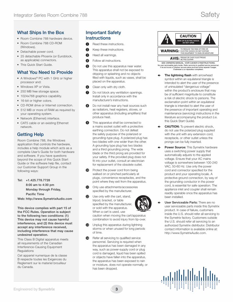
The RJ45 connectors labeled “ARC” are only for use with the ARC series of remotes.
DO NOT plug the ARC connectors on Symetrix products into any RJ45 connector labeled “SYMLINK”, “ETHERNET” or “COBRANET”.
The “ARC” RJ45 connectors on Symetrix products can carry anywhere from 6 to 24 VDC which
can damage SymLink, Ethernet and CobraNet circuitry.
ARC
ARC
SYMLINKTRANSMIT RECEIVE
COBRANET/ETHERNETETHERNET
Warning
5
Integrator Series Room Combine 788
IntroductionIntegrator Series products are designed with specific applications in mind. The Room Combine 788 is a complete solution for selectively combining or separating automixing, paging and background music in up to eight (8) rooms in hotels, banquet halls, schools, and conference venues.
Today’s hospitality and meeting centers demand sophisticated audio systems that are easy to operate. The 788 delivers with complete signal processing, automixing and combining of eight (8) microphones and four(4)backgroundmusic(BGM)sourcesintoasmanyas eight (8) rooms, each with comprehensive loudspeaker management.Combinationsofaudio,page,andBGMrouting, including non-adjacent spaces, are assigned in the setupsoftware.Buteaseofsetupisonlyhalfthestory.
The other half is real time user control. Our ARC-SWK wall panel (sold separately) is perfectly suited for audio sourceselectionandvolumecontrol.MultipleARC-SWK’sdynamically synchronize as spaces are combined and separated. Preset room combinations can be recalled from the 788’s front panel, the ARC-2i wall panel, or your favorite third-party control system. The 788 also easily accommodates “soft wall” sensors with its eight (8) analog control inputs for a simple, foolproof triggering of combinations.
As with all of the Integrator Series products, ease of integration is key. Software Wizards effortlessly guide connection, wall panel programming, and graphical layout of the rooms and their relationships. Room Combine 788, Engineered by Symetrix to save integrators time and money.
Features• Theeasiesttoconfigurecompleteroomcombining
solution for hotels, banquet halls, schools and conference venues.
• Eight(8)Mic/LineInputswithfilters,EQ,andfeedbackelimination into Gain-sharing Automixing, assignable to any of the eight rooms or used as a common paging source.
• Four(4)LineInputsfeaturingfilters,EQandAutomaticGainControl(AGC),handleallBackgroundMusic(BGM)with ease.
• Eight(8)Outputs:Routeaudiotoasmanyaseight(8)unique rooms, common or overflow areas.
• Wizard-drivensoftwareset-up;networkready.
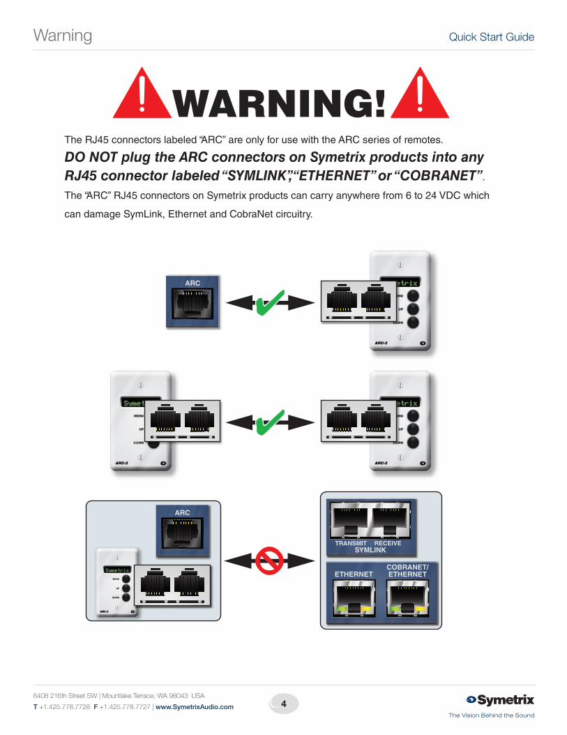
PERFORMANCE DATA
Item Specifications
Sampling Rate 48 kHz, +/- 100 ppm
Frequency Response 20Hz–20kHz,+/-0.5dB
Dynamic Range >110dB(A-weighted)
Total THD+Noise -85dBtypicalat+22dBu,1kHz,0dBgain
Input Impedance > 4 kΩ balanced, > 2 kΩ unbalanced
Output Impedance 200 Ω balanced, 100 Ω unbalanced
Maximum Input Level +23dBu
Maximum Output Level
+24dBu
Mic Pre-amp EIN <-127dBu,22Hz-22kHz,100Ωsourceimpedance
Mic Pre-amp Gain +20dB,+40dBor+50dB,micinputs;+0dBuor+11.8dBu,lineinputs(bothviainternaljumpers)
Phantom Power +48 VDC
Input CMRR >55dB@1kHz,unitygain
Interchannel Crosstalk >-90dB@1kHz,typical
Introduction•PerformanceData

6
Quick Start Guide
6408 216th Street SW | Mountlake Terrace, WA 98043 USA
T +1.425.778.7728 F +1.425.778.7727 | www.SymetrixAudio.com
Mechanical Data
Item Specifications Remarks
Space Required 1U (WDH: 48.02 cm x 22.15 cm x 4.37 cm / 18.91 in x 8.72 in x 1.72 in), depth is specified from front panel to back of connectors.
Allow at least 1 inch additional clearance for rear panel connections. Additional depth may be required depending upon your specific wiring and connections.
Electrical 100 – 240 VAC, 50/60 Hz, 25 Watts maximum. Nolinevoltageswitchingrequired.
Ventilation Maximumrecommendedambientoperatingtemperature is 30 C / 86 F.
Ensure that the left and right equipment sides are unobstructed (5.08 cm, 2 in. mini-mum clearance). The ventilation should not be impeded by covering the ventilation openings with items such as newspapers, tablecloths, curtains, etc.
Weight 8.15 lbs. (3.70 kg)
Front Panel
Item Description Comments
MENU / UP / DOWN Momentarypushbuttons •PressMENUwhileonthehomeoridlescreentocyclethroughmenusprogramed into the front panel control interface.
•PressMENUafteradjustingaparametertoconfirmyourselection(asinPresets)or to cycle to the next menu.
•PressandHoldMENUforatleast5secondstoenterorexittheSystemMenu.
•PresstheUPbuttontoadjustaparameterUP.
•PresstheDOWNbuttontoadjustaparameterDOWN.
Mic/Line Inputs Twelve(12)Bi-colorLEDs Illuminategreentoindicatesignalpresent(>-26dBu),amberbetween+5and+22.5dBuandredtoindicateclipping(>+22.5dBu)oninputs1through12.
Outputs Eight(8)Bi-colorLEDs Illuminategreentoindicatesignalpresent(>-26dBu),amberbetween+5and+23dBuandredtoindicateclipping(>+23dBu)onoutputs1through8.
Power GreenLED Illuminates to indicate the device is powered on.
Network Bi-colorLED Illuminates green to indicate a network (Ethernet) activity, amber to indicate acquisi-tion of a network address in DHCP mode.
ARC GreenLED Illuminates to indicate ARC port (RS-485) connection.
MechanicalData•FrontPanel
7
Integrator Series Room Combine 788
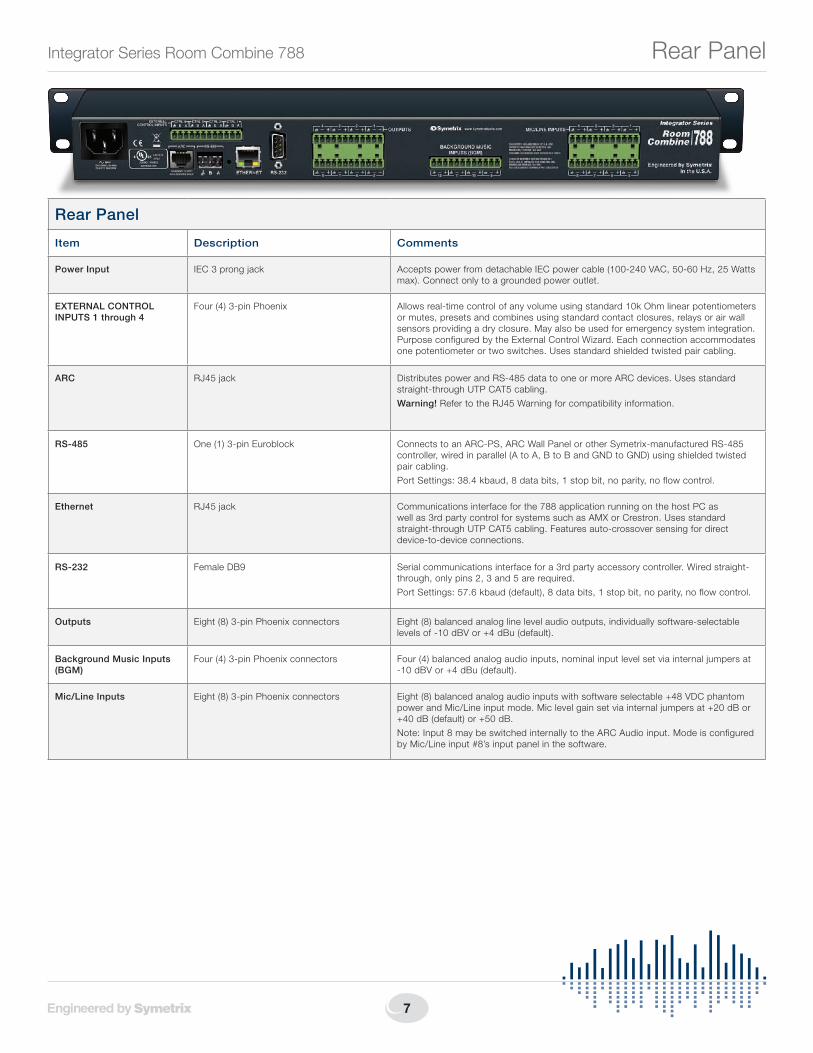
Rear Panel
Item Description Comments
Power Input IEC 3 prong jack Accepts power from detachable IEC power cable (100-240 VAC, 50-60 Hz, 25 Watts max). Connect only to a grounded power outlet.
EXTERNAL CONTROL INPUTS 1 through 4
Four (4) 3-pin Phoenix Allows real-time control of any volume using standard 10k Ohm linear potentiometers or mutes, presets and combines using standard contact closures, relays or air wall sensorsprovidingadryclosure.Mayalsobeusedforemergencysystemintegration.Purpose configured by the External Control Wizard. Each connection accommodates one potentiometer or two switches. Uses standard shielded twisted pair cabling.
ARC RJ45 jack Distributes power and RS-485 data to one or more ARC devices. Uses standard straight-through UTP CAT5 cabling.
Warning! Refer to the RJ45 Warning for compatibility information.
RS-485 One (1) 3-pin Euroblock Connects to an ARC-PS, ARC Wall Panel or other Symetrix-manufactured RS-485 controller,wiredinparallel(AtoA,BtoBandGNDtoGND)usingshieldedtwistedpair cabling.
Port Settings: 38.4 kbaud, 8 data bits, 1 stop bit, no parity, no flow control.
Ethernet RJ45 jack Communications interface for the 788 application running on the host PC as wellas3rdpartycontrolforsystemssuchasAMXorCrestron.Usesstandardstraight-through UTP CAT5 cabling. Features auto-crossover sensing for direct device-to-device connections.
RS-232 FemaleDB9 Serial communications interface for a 3rd party accessory controller. Wired straight-through, only pins 2, 3 and 5 are required.
Port Settings: 57.6 kbaud (default), 8 data bits, 1 stop bit, no parity, no flow control.
Outputs Eight (8) 3-pin Phoenix connectors Eight (8) balanced analog line level audio outputs, individually software-selectable levelsof-10dBVor+4dBu(default).
Background Music Inputs (BGM)
Four (4) 3-pin Phoenix connectors Four (4) balanced analog audio inputs, nominal input level set via internal jumpers at -10dBVor+4dBu(default).
Mic/Line Inputs Eight (8) 3-pin Phoenix connectors Eight (8) balanced analog audio inputs with software selectable +48 VDC phantom powerandMic/Lineinputmode.Miclevelgainsetviainternaljumpersat+20dBor+40dB(default)or+50dB.
Note:Input8maybeswitchedinternallytotheARCAudioinput.ModeisconfiguredbyMic/Lineinput#8’sinputpanelinthesoftware.
Rear Panel

8
Quick Start Guide
6408 216th Street SW | Mountlake Terrace, WA 98043 USA
T +1.425.778.7728 F +1.425.778.7727 | www.SymetrixAudio.com
PowerPOWER INPUT Connect the IEC connector end of the supplied AC cord
to the receptacle on the rear of the 788. Connect the AC connector end of the supplied AC cord to an AC power source that is of the correct voltage and frequency (100-240 VAC, 50-60 Hz). Use only the power cord and connector specified for the product and your operating locale.
Whenthe788ispoweredupcorrectly,thePOWERLEDonthe front of the unit will be lit solid green.
External ControlEXT CTRL 1 — 4 Using standard shielded twisted pair terminated with a
Phoenix connector on one end, you may connect up to two contactclosuresoronepotentiometertoeachEXTERNALCONTROLinput.ConfigurationoftheEXTERNALCONTROLinputs is done with the External Control Wizard. These ports may also be used to integrate with an alarm or emergency system.
EthernetRJ45 Connector Using a standard straight-through CAT5 cable terminated
withRJ45connectors,connectthe788’sETHERNETportto either your computer’s Ethernet port or to an existing Ethernetnetwork.YoumaywishtoreviewtheNetworkConfiguration section for more information.
When the 788 has a physical network connection, the amber“link”LEDontheETHERNETconnectorwillbelitsolid.
Whenthereisnetworkcommunication,thegreen“activity”LEDontheETHERNETconnectorandtheNETWORKLEDonthefrontoftheunitwillflash accordingly.
NOTE: The 788’s Ethernet port will automatically sense a device-to-device connection so that a standard straight-through Ethernet cable may always be used. A cross-over cable is not required.
ARCARC Using a standard straight-through CAT5 cable terminated
with RJ45 connectors or standard shielded twisted pair terminated with a Euroblock on one end, connect your ARC Wall Panels to either the ARC or RS-485 ports according to theguidelinesintheARCNetworkDesignsection.
When an ARC Wall Panel network is connected to the 788, thegreenARCLEDonthefrontoftheunitwillbelitsolidgreen.
WARNING: When designing an ARC network, one must be careful not to double power any ARCs. If all pins on the CAT5 connections are used, power can travel over the CAT5 cable and reach any ARC on that particular chain. Power over CAT5 could potentially come from the ARC that is powered locally and then daisy-chained via CAT5 to other ARCs or directly from a particular ARC’s terminal block connections. In general, we recommend using only one type of power connection on the ARCs, either the RJ45s (with CAT5 cable) or the terminal blocks but not both.
CAUTION: DONOTplugtheRJ45connectorsofanARCWallPanelintoanyRJ45connectorlabeled“ETHERNET”,“COBRALINK”or“SYMLINK”.Refer to the RJ45 Warning for compatibility information.
Hardware Connections
9
Integrator Series Room Combine 788
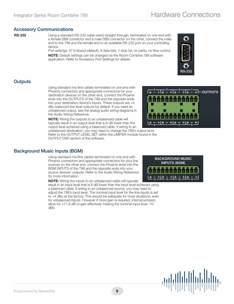
Accessory CommunicationsRS-232 Using a standard RS-232 cable wired straight-through, terminated on one end with
afemaleDB9connectorandamaleDB9connectorontheother,connectthemaleend to the 788 and the female end to an available RS-232 port on your controlling device. Port settings: 57.6 kbaud (default), 8 data bits, 1 stop bit, no parity, no flow control.
NOTE: Default settings can be changed via the Room Combine 788 software application. Refer to Accessory Port Settings for details.
Outputs Using standard mic/line cables terminated on one end with
Phoenix connectors and appropriate connectors for your destination devices on the other end, connect the Phoenix ends into the OUTPUTS of the 788 and the opposite ends into your destination device’s inputs. These outputs are +4 dBubalancedlineleveloutputsbydefault.Ifyouneedanunbalanced output, see the analog audio wiring diagrams in the Audio Wiring Reference.
NOTE: Wiring the outputs to an unbalanced cable will typicallyresultinanoutputlevelthatis6dBlowerthantheoutput level achieved using a balanced cable. If wiring to an unbalanced destination, you may need to change the 788’s output level. RefertotheOUTPUTLEVELSETwithintheLIMITERmodulefoundintheOUTPUT DSP section of the software.
Background Music Inputs (BGM) Using standard mic/line cables terminated on one end with
Phoenix connectors and appropriate connectors for your line sources on the other end, connect the Phoenix ends into the BGMINPUTSofthe788andtheoppositeendsintoyoursource devices’ outputs. Refer to the Audio Wiring Reference for more information.
NOTE: Wiring the inputs to an unbalanced cable will typically resultinaninputlevelthatis6dBlowerthantheinputlevelachievedusinga balanced cable. If wiring to an unbalanced source, you may need to adjust the 788’s input level. The nominal input level for the line inputs is set to+4dBuatthefactory.Thisshouldbeadequateformostsituations,evenfor unbalanced inputs. However if more gain is required, internal jumpers allowfor+11.8dBofgaineffectivelymakingthenominalinputlevel-10dBV.
Hardware Connections
10
Quick Start Guide
6408 216th Street SW | Mountlake Terrace, WA 98043 USA
T +1.425.778.7728 F +1.425.778.7727 | www.SymetrixAudio.com
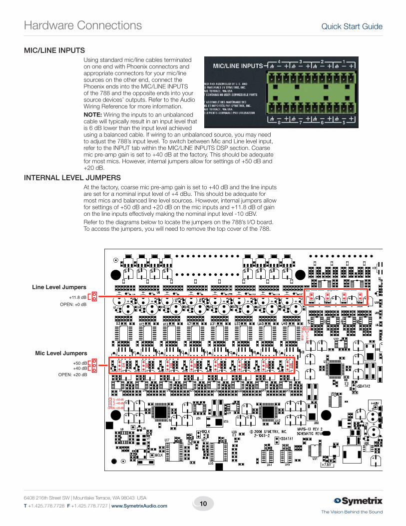
MIC/LINE INPUTS Using standard mic/line cables terminated
on one end with Phoenix connectors and appropriate connectors for your mic/line sources on the other end, connect the PhoenixendsintotheMIC/LINEINPUTSof the 788 and the opposite ends into your source devices’ outputs. Refer to the Audio Wiring Reference for more information.
NOTE: Wiring the inputs to an unbalanced cable will typically result in an input level that is6dBlowerthantheinputlevelachievedusing a balanced cable. If wiring to an unbalanced source, you may need toadjustthe788’sinputlevel.ToswitchbetweenMicandLinelevelinput,refertotheINPUTtabwithintheMIC/LINEINPUTSDSPsection.Coarsemicpre-ampgainissetto+40dBatthefactory.Thisshouldbeadequateformostmics.However,internaljumpersallowforsettingsof+50dBand+20dB.
INTERNAL LEVEL JUMPERS Atthefactory,coarsemicpre-ampgainissetto+40dBandthelineinputs
aresetforanominalinputlevelof+4dBu.Thisshouldbeadequateformost mics and balanced line level sources. However, internal jumpers allow forsettingsof+50dBand+20dBonthemicinputsand+11.8dBofgainonthelineinputseffectivelymakingthenominalinputlevel-10dBV.
Refer to the diagrams below to locate the jumpers on the 788’s I/O board. To access the jumpers, you will need to remove the top cover of the 788.
+50 dB +40 dB
OPEN: +20 dB
+11.8 dB
OPEN: +0 dB
+11.8 dB
Line Level Jumpers
OPEN: +0 dB
+50 dB+40 dB
OPEN: +20 dB
Mic Level Jumpers
Hardware Connections
11
Integrator Series Room Combine 788
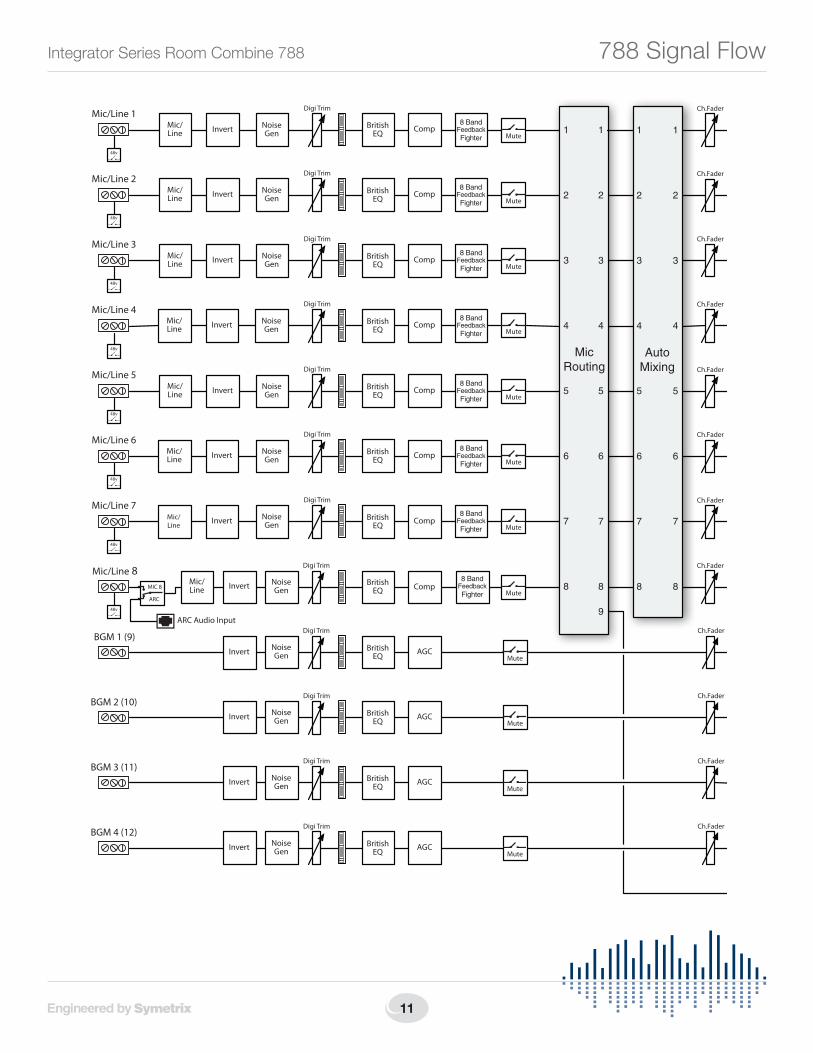
PageStation
Mic/Line 8
48v
ARC Audio Input
8 BandFeedbackFighter
Loudspeaker Manager
Delay HPF LPF Inv. Limiter
Output 1Gain Set-10/+4
8 BandParametric
EQ
Loudspeaker Manager
Delay HPF LPF Inv. Limiter
Output 2Gain Set-10/+4
8 BandParametric
EQ
Loudspeaker Manager
Delay HPF LPF Inv. Limiter
Output 3Gain Set-10/+4
8 BandParametric
EQ
Loudspeaker Manager
Delay HPF LPF Inv. Limiter
Output 4Gain Set-10/+4
8 BandParametric
EQ
Loudspeaker Manager
Delay HPF LPF Inv. Limiter
Output 5Gain Set-10/+4
8 BandParametric
EQ
Loudspeaker Manager
Delay HPF LPF Inv. Limiter
Output 6Gain Set-10/+4
8 BandParametric
EQ
Loudspeaker Manager
Delay HPF LPF Inv. Limiter
Output 7Gain Set-10/+4
8 BandParametric
EQ
Loudspeaker Manager
Delay HPF LPF Inv. Limiter
Output 8Gain Set-10/+4
8 BandParametric
EQ
Digi TrimMic/Line 1
48v
8 BandFeedbackFighter
Invert NoiseGen
BritishEQ Comp
Digi TrimMic/Line 2
48v
8 BandFeedbackFighter
NoiseGen
BritishEQ Comp
Digi TrimMic/Line 3
48v
8 BandFeedbackFighter
NoiseGen
BritishEQ Comp
Digi TrimMic/Line 4
48v
8 BandFeedbackFighter
NoiseGen Comp
Digi TrimMic/Line 5
48v
8 BandFeedbackFighter
NoiseGen
BritishEQ
Digi TrimMic/Line 6
48v
8 BandFeedbackFighter
NoiseGen
BritishEQ Comp
Mic/Line 7
48v
8 BandFeedbackFighter
NoiseGen
BritishEQ Comp
NoiseGen
BritishEQ Comp
Digi TrimBGM 1 (9)
Invert NoiseGen
BritishEQ AGC
Digi TrimBGM 2 (10)
Invert NoiseGen
BritishEQ AGC
Digi TrimBGM 3 (11)
Invert NoiseGen
BritishEQ AGC
Digi TrimBGM 4 (12)
Invert NoiseGen
BritishEQ AGC
Digi Trim
Ch.Fader
Mic/Line
InvertMic/Line
InvertMic/Line
InvertMic/Line
InvertMic/Line
InvertMic/Line
InvertMic/Line
InvertMic/Line
Digi Trim
BritishEQ
Comp
Ch.Fader
Ch.Fader
Ch.Fader
Ch.Fader
Ch.Fader
Ch.Fader
Ch.Fader
Ch.Fader
Ch.Fader
Ch.Fader
Ch.Fader
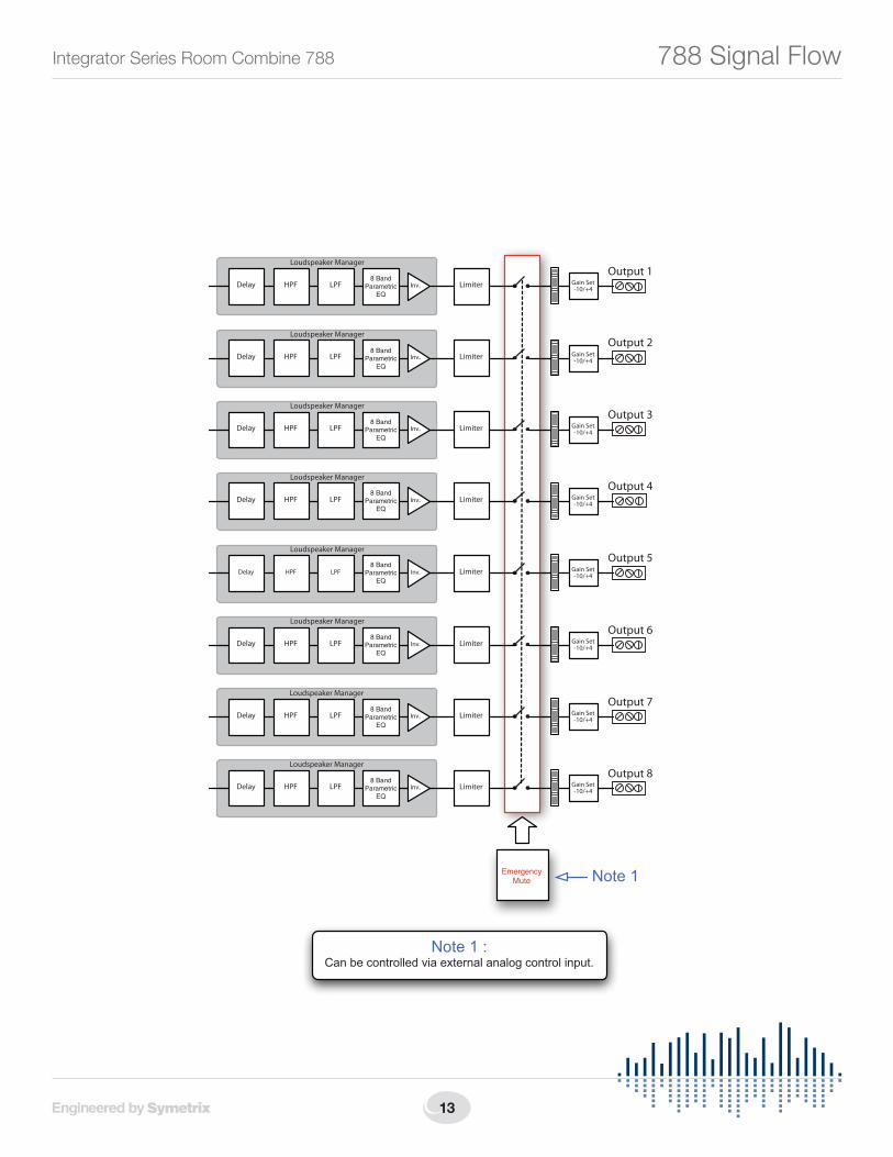
EmergencyMute Note 1
Note 1 : Can be controlled via external analog control input.
Paging
MicRouting
Room Vol.
Room Vol.
Room Vol.
Room Vol.
Room Vol.
Room Vol.
Room Vol.
Room Vol.
RoomCombining
& BMGSelection
AutoMixing
1
2
3
4
5
6
7
8
1
2
3
4
5
6
7
8
9
10
11
12
1
2
3
4
5
6
7
8
1
2
3
4
5
6
7
8
1
2
3
4
5
6
7
8
9
1
2
3
4
5
6
7
8
1
2
3
4
5
6
7
8
1
2
3
4
5
6
7
8
1
2
3
4
5
6
7
8
DuckerSide Chain
DuckerSide Chain
DuckerSide Chain
DuckerSide Chain
DuckerSide Chain
DuckerSide Chain
DuckerSide Chain
DuckerSide Chain
1
ARC
MIC 8
Mute
Mute
Mute
Mute
Mute
Mute
Mute
Mute
Mute
Mute
Mute
Mute
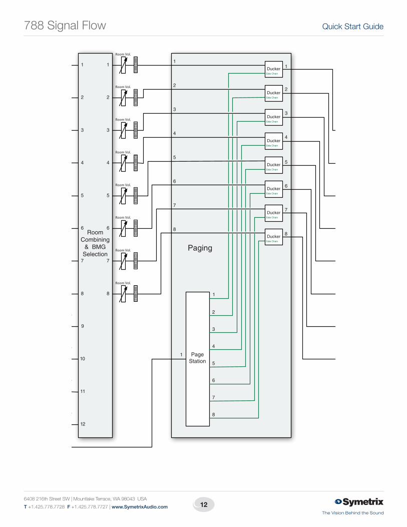
788 Signal Flow
12
Quick Start Guide
6408 216th Street SW | Mountlake Terrace, WA 98043 USA
T +1.425.778.7728 F +1.425.778.7727 | www.SymetrixAudio.com
PageStation
Mic/Line 8
48v
ARC Audio Input
8 BandFeedbackFighter
Loudspeaker Manager
Delay HPF LPF Inv. Limiter
Output 1Gain Set-10/+4
8 BandParametric
EQ
Loudspeaker Manager
Delay HPF LPF Inv. Limiter
Output 2Gain Set-10/+4
8 BandParametric
EQ
Loudspeaker Manager
Delay HPF LPF Inv. Limiter
Output 3Gain Set-10/+4
8 BandParametric
EQ
Loudspeaker Manager
Delay HPF LPF Inv. Limiter
Output 4Gain Set-10/+4
8 BandParametric
EQ
Loudspeaker Manager
Delay HPF LPF Inv. Limiter
Output 5Gain Set-10/+4
8 BandParametric
EQ
Loudspeaker Manager
Delay HPF LPF Inv. Limiter
Output 6Gain Set-10/+4
8 BandParametric
EQ
Loudspeaker Manager
Delay HPF LPF Inv. Limiter
Output 7Gain Set-10/+4
8 BandParametric
EQ
Loudspeaker Manager
Delay HPF LPF Inv. Limiter
Output 8Gain Set-10/+4
8 BandParametric
EQ
Digi TrimMic/Line 1
48v
8 BandFeedbackFighter
Invert NoiseGen
BritishEQ Comp
Digi TrimMic/Line 2
48v
8 BandFeedbackFighter
NoiseGen
BritishEQ Comp
Digi TrimMic/Line 3
48v
8 BandFeedbackFighter
NoiseGen
BritishEQ Comp
Digi TrimMic/Line 4
48v
8 BandFeedbackFighter
NoiseGen Comp
Digi TrimMic/Line 5
48v
8 BandFeedbackFighter
NoiseGen
BritishEQ
Digi TrimMic/Line 6
48v
8 BandFeedbackFighter
NoiseGen
BritishEQ Comp
Mic/Line 7
48v
8 BandFeedbackFighter
NoiseGen
BritishEQ Comp
NoiseGen
BritishEQ Comp
Digi TrimBGM 1 (9)
Invert NoiseGen
BritishEQ AGC
Digi TrimBGM 2 (10)
Invert NoiseGen
BritishEQ AGC
Digi TrimBGM 3 (11)
Invert NoiseGen
BritishEQ AGC
Digi TrimBGM 4 (12)
Invert NoiseGen
BritishEQ AGC
Digi Trim
Ch.Fader
Mic/Line
InvertMic/Line
InvertMic/Line
InvertMic/Line
InvertMic/Line
InvertMic/Line
InvertMic/Line
InvertMic/Line
Digi Trim
BritishEQ
Comp
Ch.Fader
Ch.Fader
Ch.Fader
Ch.Fader
Ch.Fader
Ch.Fader
Ch.Fader
Ch.Fader
Ch.Fader
Ch.Fader
Ch.Fader
EmergencyMute Note 1
Note 1 : Can be controlled via external analog control input.
Paging
MicRouting
Room Vol.
Room Vol.
Room Vol.
Room Vol.
Room Vol.
Room Vol.
Room Vol.
Room Vol.
RoomCombining
& BMGSelection
AutoMixing
1
2
3
4
5
6
7
8
1
2
3
4
5
6
7
8
9
10
11
12
1
2
3
4
5
6
7
8
1
2
3
4
5
6
7
8
1
2
3
4
5
6
7
8
9
1
2
3
4
5
6
7
8
1
2
3
4
5
6
7
8
1
2
3
4
5
6
7
8
1
2
3
4
5
6
7
8
DuckerSide Chain
DuckerSide Chain
DuckerSide Chain
DuckerSide Chain
DuckerSide Chain
DuckerSide Chain
DuckerSide Chain
DuckerSide Chain
1
ARC
MIC 8
Mute
Mute
Mute
Mute
Mute
Mute
Mute
Mute
Mute
Mute
Mute
Mute
788 Signal Flow
13
Integrator Series Room Combine 788
PageStation
Mic/Line 8
48v
ARC Audio Input
8 BandFeedbackFighter
Loudspeaker Manager
Delay HPF LPF Inv. Limiter
Output 1Gain Set-10/+4
8 BandParametric
EQ
Loudspeaker Manager
Delay HPF LPF Inv. Limiter
Output 2Gain Set-10/+4
8 BandParametric
EQ
Loudspeaker Manager
Delay HPF LPF Inv. Limiter
Output 3Gain Set-10/+4
8 BandParametric
EQ
Loudspeaker Manager
Delay HPF LPF Inv. Limiter
Output 4Gain Set-10/+4
8 BandParametric
EQ
Loudspeaker Manager
Delay HPF LPF Inv. Limiter
Output 5Gain Set-10/+4
8 BandParametric
EQ
Loudspeaker Manager
Delay HPF LPF Inv. Limiter
Output 6Gain Set-10/+4
8 BandParametric
EQ
Loudspeaker Manager
Delay HPF LPF Inv. Limiter
Output 7Gain Set-10/+4
8 BandParametric
EQ
Loudspeaker Manager
Delay HPF LPF Inv. Limiter
Output 8Gain Set-10/+4
8 BandParametric
EQ
Digi TrimMic/Line 1
48v
8 BandFeedbackFighter
Invert NoiseGen
BritishEQ Comp
Digi TrimMic/Line 2
48v
8 BandFeedbackFighter
NoiseGen
BritishEQ Comp
Digi TrimMic/Line 3
48v
8 BandFeedbackFighter
NoiseGen
BritishEQ Comp
Digi TrimMic/Line 4
48v
8 BandFeedbackFighter
NoiseGen Comp
Digi TrimMic/Line 5
48v
8 BandFeedbackFighter
NoiseGen
BritishEQ
Digi TrimMic/Line 6
48v
8 BandFeedbackFighter
NoiseGen
BritishEQ Comp
Mic/Line 7
48v
8 BandFeedbackFighter
NoiseGen
BritishEQ Comp
NoiseGen
BritishEQ Comp
Digi TrimBGM 1 (9)
Invert NoiseGen
BritishEQ AGC
Digi TrimBGM 2 (10)
Invert NoiseGen
BritishEQ AGC
Digi TrimBGM 3 (11)
Invert NoiseGen
BritishEQ AGC
Digi TrimBGM 4 (12)
Invert NoiseGen
BritishEQ AGC
Digi Trim
Ch.Fader
Mic/Line
InvertMic/Line
InvertMic/Line
InvertMic/Line
InvertMic/Line
InvertMic/Line
InvertMic/Line
InvertMic/Line
Digi Trim
BritishEQ
Comp
Ch.Fader
Ch.Fader
Ch.Fader
Ch.Fader
Ch.Fader
Ch.Fader
Ch.Fader
Ch.Fader
Ch.Fader
Ch.Fader
Ch.Fader
EmergencyMute Note 1
Note 1 : Can be controlled via external analog control input.
Paging
MicRouting
Room Vol.
Room Vol.
Room Vol.
Room Vol.
Room Vol.
Room Vol.
Room Vol.
Room Vol.
RoomCombining
& BMGSelection
AutoMixing
1
2
3
4
5
6
7
8
1
2
3
4
5
6
7
8
9
10
11
12
1
2
3
4
5
6
7
8
1
2
3
4
5
6
7
8
1
2
3
4
5
6
7
8
9
1
2
3
4
5
6
7
8
1
2
3
4
5
6
7
8
1
2
3
4
5
6
7
8
1
2
3
4
5
6
7
8
DuckerSide Chain
DuckerSide Chain
DuckerSide Chain
DuckerSide Chain
DuckerSide Chain
DuckerSide Chain
DuckerSide Chain
DuckerSide Chain
1
ARC
MIC 8
Mute
Mute
Mute
Mute
Mute
Mute
Mute
Mute
Mute
Mute
Mute
Mute
788 Signal Flow

14
Quick Start Guide
6408 216th Street SW | Mountlake Terrace, WA 98043 USA
T +1.425.778.7728 F +1.425.778.7727 | www.SymetrixAudio.com
15
Integrator Series Room Combine 788
XLR Male Plug [balanced]
Pin 2Pin 3Pin 1
Pin 2 = (+) PlusPin 3 = (–) MinusPin 1 = Ground
XLR Female Plug [balanced]
Pin 2 = (+) PlusPin 3 = (–) MinusPin 1 = Ground
Pin 2Pin 3Pin 1
Terminal Strip [balanced] TRS 1/4" Plug [balanced]
Tip = (+) PlusRing = (–) MinusSleeve = Ground
Euroblock [balanced]
NOTE: Detachable Euroblock and Terminal Strip connectors are designed for use with bare wire. Do not tin stranded wires before inserting them into the connectors.
Special Case: Female XLR connectors willALWAYS be used coming from the OUTPUT of a device.Male connecters plug into the INPUT of a device.
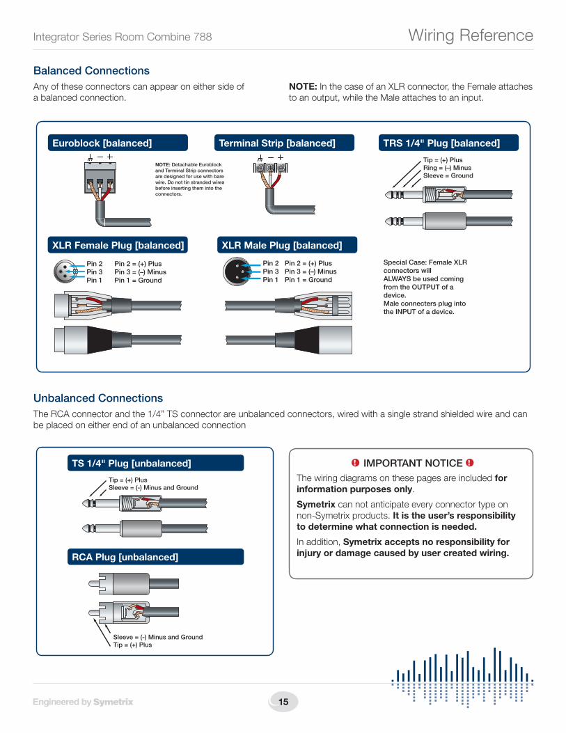
Balanced ConnectionsAny of these connectors can appear on either side of a balanced connection.
NOTE:InthecaseofanXLRconnector,theFemaleattachestoanoutput,whiletheMaleattachestoaninput.
Unbalanced ConnectionsThe RCA connector and the 1/4” TS connector are unbalanced connectors, wired with a single strand shielded wire and can be placed on either end of an unbalanced connection
TS 1/4" Plug [unbalanced]
Tip = (+) PlusSleeve = (-) Minus and Ground
RCA Plug [unbalanced]
Sleeve = (-) Minus and GroundTip = (+) Plus
1! IMPORTANT NOTICE 1!
The wiring diagrams on these pages are included for information purposes only.
Symetrix can not anticipate every connector type on non-Symetrix products. It is the user’s responsibility to determine what connection is needed.
In addition, Symetrix accepts no responsibility for injury or damage caused by user created wiring.
Wiring Reference
16
Quick Start Guide
6408 216th Street SW | Mountlake Terrace, WA 98043 USA
T +1.425.778.7728 F +1.425.778.7727 | www.SymetrixAudio.com
Unbalanced Connections:Unbalanced out to balanced inThe RCA connector and the 1/4” TS connector are unbalanced connectors. However, the wiring differs depending on if they are sending to, or receiving from a balanced connector.
In this example, the unbalanced connector is sending signal to a balanced connector. When wiring this connection, use a shielded twisted pair cable. The balanced side wires the same as a standard, balanced connection. On the unbalanced side, you wire the white (minus) wire together with the ground. This provides some common mode rejection at the balanced input.
Unbalanced Connections:Balanced out to unbalanced inWhen your output requires a balanced connector, but you
are sending signal to an unbalanced input, the rules change. Use a single strand shielded wire. Wire only to the plus and ground terminals of what would typically be the balanced connector.
XLR Male Plug [balanced]
TS 1/4" Plug [unbalanced out to balanced in]
TRS 1/4" Plug [balanced]
Euroblock [balanced]
Tip = (+) PlusSleeve = (-) Minus and Ground
RCA Plug [unbalanced out to balanced in]
Sleeve = (-) Minus and GroundTip = (+) Plus
Terminal Strip [balanced]
TS 1/4" Plug [balanced out to unbalanced in]
Tip = (+) PlusSleeve = Ground
RCA Plug [balanced out to unbalanced in]
Sleeve = GroundTip = (+) Plus
Euroblock [unbalanced] Terminal Strip [unbalanced]
XLR Female Plug [unbalanced]
Pin 2 = (+) PlusPin 3 = UnusedPin 1 = Ground
Pin 2Pin 3Pin 1
TRS 1/4" Plug [balanced]Tip = (+) PlusRing = UnusedSleeve = Ground
Wiring Reference

17
Integrator Series Room Combine 788
Network Configuration
TThe 788 is setup and controlled by a host computer via Ethernet. This requires the host computer to be connected to the 788 directly via a standard CAT5 Ethernet cable, indirectly via an Ethernet switch, or via an existing Ethernet network.
The primary difference between the three methods of connection is that in the first two, the 788 software application assumes there is no DHCP server or other network infrastructure in place. It assumes the 788 is using a self-generated IP address and adjusts its connection steps appropriately. In the third method, it is assumed that a DHCP server and/or router with DHCP server are already present on the existing network so the 788 may already have obtained an IP address. Consult your network administrator if in doubt.
General Notes1. The 788 boots up with DHCP enabled by default. This
means that as soon as you connect it to a network, it will look for a DHCP server in order to obtain an IP address. If a DHCP server is present, the 788 will get its IP address from it. This process may take several minutes. With your PC attached to the same network and thus getting its IP address from the same DHCP server, all will be ready to go.
2. If your network does not have a DHCP server, the 788 will not be able to obtain an IP address. While waiting, the 788 will default to a private IP address in the range of 169.254.x.x where x.x is the last four alphanumeric charactersofthe788’sMACaddress.The788’sMACaddress can be found on a sticker on the bottom of the 788 or within the front panel System menu. When there is no DHCP server present to assign IP addresses to either the 788 or your PC, you may need to configure your PC
with a static IP in the range of 169.254.x.x with a Subnet Maskof255.255.0.0inordertocommunicatewiththe788 in a direct connect mode. However, if your PC is using the default network settings, it should also have automatically self-assigned a similar private IP address in the range of 169.254.x.x, and if this is the case, you should be able to connect to the 788 directly. Even if the PC’s default settings have been changed, the 788 will try to establish communications by setting up appropriate routing table entries to reach devices with 169.254.x.x addresses.
3. In the case of the first two methods (direct connection and indirect connection), the 788 software will attempt to set-up appropriate routing table entries for a seamless connection regardless of the IP addresses of your PC and 788. However, under Windows® Vista, administrative privileges are required to allow the 788 software to modify the routing table. For best results, launch the 788 software while logged in as an administrator, or choose to run the software as an administrator. Note: To run a program as the Administrator under Vista, right click on the program’s icon or shortcut and choose “Run as administrator”.
4. The 788 will display its current IP address, subnet mask, and gateway as well as other useful information onthefrontpaneldisplaywheninSystemMode.ToenterSystemMode,holddowntheMenubuttonfor5seconds. Then the up and down arrow keys can be used to move between various displays. This information may be useful for troubleshooting.
Network configuration of the 788:Connecting to the 788 from a host computer on the same LANBoththe788andthehostcomputerrequirethefollowing 3 items:
1. IP Address - The unique address of a node on a network.
2.SubnetMask-ConfigurationthatdefineswhichIPAddresses are included in a particular subnet.
3. Default Gateway (optional) - The IP address of a device that routes traffic from one subnet to another. (This is only needed when the PC and 788 are on different subnets).
If you are putting the 788 on an existing network, a network administrator will be able to provide the above information or it may have been provided automatically by a DHCP server. For security reasons, it is not recommended to put the 788 directly on the Internet. If you do, a network administrator or your Internet Service Provider can provide the above information.
788Networking

18
Quick Start Guide
6408 216th Street SW | Mountlake Terrace, WA 98043 USA
T +1.425.778.7728 F +1.425.778.7727 | www.SymetrixAudio.com
If you are on your own private network, directly or indirectly connected to the 788, you may allow the 788 to choose an automatic IP address or you may choose to to assign it a static IP address. If you are building your own separate network with static assigned addresses, you may consider using an IP Address from one of the ”Private-Use” networks noted in RFC-1918:
1. 172.16.0.0/12 = IP Addresses 172.16.0.1 through 172.31.254.254andaSubnetMaskof255.240.0.0
2. 192.168.0.0/16 = IP Addresses 192.168.0.1 through 192.168.254.254andaSubnetMaskof255.255.0.0
3. 10.0.0.0/8 = IP Addresses 10.0.0.1 through 10.254.254.254andaSubnetMaskof255.255.0.0
Connecting to the 788 through a Firewall/VPNWe have successfully tested control of a 788 through a firewallandVPN,butareunabletoguaranteeperformanceof these types of connections at this time. Configuration instructionsarespecifictoeachfirewallandVPN,so specifics are not available. Additionally, wireless communications are also not guaranteed, though have also been successfully tested.
Configuring your computer for a network connection: Windows® XP
1. Select “Start->Control Panel”.
2.Openthe“NetworkConnections”ControlPanel.
3.Rightclickonyour“LocalAreaConnection”andselect””Properties”.
4. Under “This connection uses the following items”, select “Internet Protocol (TCP/IP)” and press “Properties”.
788Networking
Router/FirewallIP: 10.0.0.1
Switch
Host Computer & PC LANIP: 10.0.0.3
SM: 255.255.0.0GW: 10.0.0.1
Room Combine 788IP: 10.0.0.2
SM: 255.255.0.0GW: 10.0.0.1
Ethernet
Ethernet
to Internet
19
Integrator Series Room Combine 788
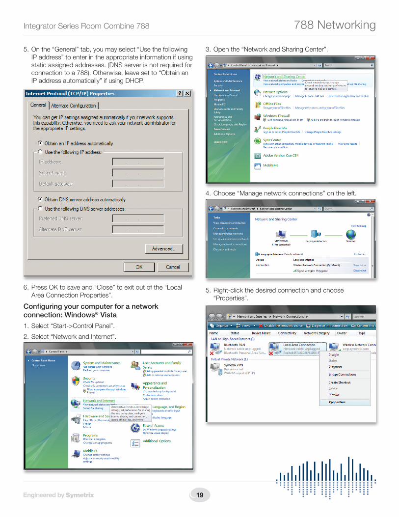
5. On the “General” tab, you may select “Use the following IP address” to enter in the appropriate information if using staticassignedaddresses.(DNSserverisnotrequiredforconnection to a 788). Otherwise, leave set to “Obtain an IP address automatically” if using DHCP.
6.PressOKtosaveand“Close”toexitoutofthe“LocalArea Connection Properties”.
Configuring your computer for a network connection: Windows® Vista
1. Select “Start->Control Panel”.
2.Select“NetworkandInternet”.
3.Openthe“NetworkandSharingCenter”.
4.Choose“Managenetworkconnections”ontheleft.
5. Right-click the desired connection and choose “Properties”.
788Networking
20
Quick Start Guide
6408 216th Street SW | Mountlake Terrace, WA 98043 USA
T +1.425.778.7728 F +1.425.778.7727 | www.SymetrixAudio.com
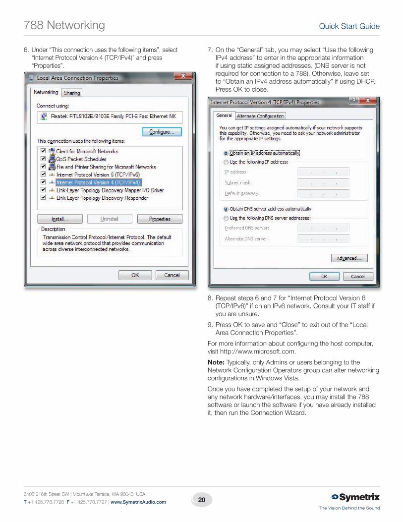
6. Under “This connection uses the following items”, select “Internet Protocol Version 4 (TCP/IPv4)” and press “Properties”.
7. On the “General” tab, you may select “Use the following IPv4 address” to enter in the appropriate information ifusingstaticassignedaddresses.(DNSserverisnotrequired for connection to a 788). Otherwise, leave set to “Obtain an IPv4 address automatically” if using DHCP. Press OK to close.
8. Repeat steps 6 and 7 for “Internet Protocol Version 6 (TCP/IPv6)” if on an IPv6 network. Consult your IT staff if you are unsure.
9.PressOKtosaveand“Close”toexitoutofthe“LocalArea Connection Properties”.
For more information about configuring the host computer, visit http://www.microsoft.com.
Note: Typically, only Admins or users belonging to the NetworkConfigurationOperatorsgroupcanalternetworkingconfigurations in Windows Vista.
Once you have completed the setup of your network and any network hardware/interfaces, you may install the 788 software or launch the software if you have already installed it, then run the Connection Wizard.
788Networking
21
Integrator Series Room Combine 788
Room Combine 788 SoftwareInstallationThe Room Combine 788 software provides real-time set-up and control from a Win dows PC environment.
Use one of the following procedures to install the Room Combine 788 software on your computer.
FromtheCD-ROM:
1. InserttheCDintoyourcomputer’sCD-ROMdrive.
2.Open“MyComputer”.The“MyComputer”iconistypically on your desktop or in the “Start” menu.
3.DoubleclickonyourCD-ROMdrive.Thisistypicallydrive“D:\”.IfyourCD-ROMdriveisn’t“D:\”,thensubstituteitsdrive letter.
4. Double-click “Setup.exe”.From the Symetrix web site (http://www.SymetrixAudio.com):
1. Download the Room Combine 788 software installer from the Symetrix web site.
2. Double-click on the file you just downloaded and follow the on screen directions to install.
The software always starts up in offline mode. Regardless, you can explore the software, experiment to your heart’s content, and perhaps even get useful work done. You can save any device files that you create to your hard drive and transfer them to hardware later.
After installing the software, browse the rest of the Help File, or move on to the Connection Wizard to get connected to your 788.
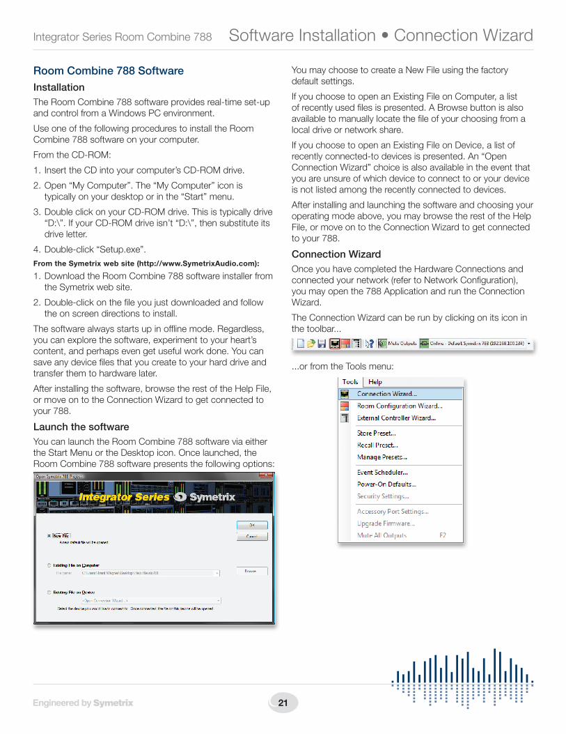
Launch the softwareYou can launch the Room Combine 788 software via either theStartMenuortheDesktopicon.Oncelaunched,theRoom Combine 788 software presents the following options:
YoumaychoosetocreateaNewFileusingthefactorydefault settings.
If you choose to open an Existing File on Computer, a list ofrecentlyusedfilesispresented.ABrowsebuttonisalsoavailable to manually locate the file of your choosing from a local drive or network share.
If you choose to open an Existing File on Device, a list of recently connected-to devices is presented. An “Open Connection Wizard” choice is also available in the event that you are unsure of which device to connect to or your device is not listed among the recently connected to devices.
After installing and launching the software and choosing your operating mode above, you may browse the rest of the Help File, or move on to the Connection Wizard to get connected to your 788.
Connection WizardOnce you have completed the Hardware Connections and connectedyournetwork(refertoNetworkConfiguration),you may open the 788 Application and run the Connection Wizard.
The Connection Wizard can be run by clicking on its icon in the toolbar...
...or from the Tools menu:
SoftwareInstallation•ConnectionWizard

22
Quick Start Guide
6408 216th Street SW | Mountlake Terrace, WA 98043 USA
T +1.425.778.7728 F +1.425.778.7727 | www.SymetrixAudio.com
The Connection Wizard opens with the following screen:
Select the option that best represents your network topologyandthenclicktheNextbutton.(RefertoNetworkConfiguration for further help.)
IntheeventthatyourcomputerhasmultipleNetworkInterfacesCards(NICs),thefollowingscreenwillallowyoutoselectthenetworkyouwishtosearchfor788devices.NotethatonlyvalidNICswillbeselectable(thosewithanetworkconnection and valid IP address).
SelecttheNICyouwishtouseandthenclicktheNextbutton.
The following screen displays a list of 788 devices found on your network. At the very least, you can select the device youwishtoconnecttoandclicktheNextbutton.However,there are a few more functions on this screen worth mentioning...
Properties:
The (device) Properties dialog allows you to give a device a unique name to help identify it. It also allows you to switch the unit between dynamic (DHCP) IP addressing and static IP addressing.
Flash Device:
ClickingtheFlashDevicebuttonwillcauseallLEDsonthefront of the device to flash for a short time. This can be helpful to distinguish units which have the same or similar names.
Upgrade Firmware:
The 788 Firmware must be matched with the version of the Room Combine Application you are using. The correct firmware for the Application is always distributed with the Application and installed on your hard drive by the Application’s installer. If there is ever any doubt, follow the instructions in the Upgrade Firmware topic to check your firmware version or to upgrade the firmware.
Connection Wizard
23
Integrator Series Room Combine 788
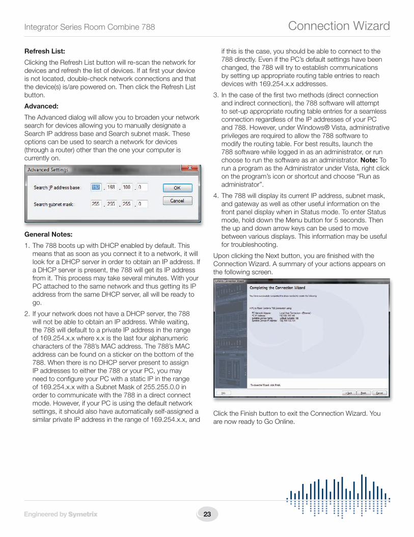
Refresh List:
ClickingtheRefreshListbuttonwillre-scanthenetworkfordevices and refresh the list of devices. If at first your device is not located, double-check network connections and that thedevice(s)is/arepoweredon.ThenclicktheRefreshListbutton.
Advanced:
The Advanced dialog will allow you to broaden your network search for devices allowing you to manually designate a Search IP address base and Search subnet mask. These options can be used to search a network for devices (through a router) other than the one your computer is currently on.
General Notes:
1. The 788 boots up with DHCP enabled by default. This means that as soon as you connect it to a network, it will look for a DHCP server in order to obtain an IP address. If a DHCP server is present, the 788 will get its IP address from it. This process may take several minutes. With your PC attached to the same network and thus getting its IP address from the same DHCP server, all will be ready to go.
2. If your network does not have a DHCP server, the 788 will not be able to obtain an IP address. While waiting, the 788 will default to a private IP address in the range of 169.254.x.x where x.x is the last four alphanumeric charactersofthe788’sMACaddress.The788’sMACaddress can be found on a sticker on the bottom of the 788. When there is no DHCP server present to assign IP addresses to either the 788 or your PC, you may need to configure your PC with a static IP in the range of169.254.x.xwithaSubnetMaskof255.255.0.0inorder to communicate with the 788 in a direct connect mode. However, if your PC is using the default network settings, it should also have automatically self-assigned a similar private IP address in the range of 169.254.x.x, and
if this is the case, you should be able to connect to the 788 directly. Even if the PC’s default settings have been changed, the 788 will try to establish communications by setting up appropriate routing table entries to reach devices with 169.254.x.x addresses.
3. In the case of the first two methods (direct connection and indirect connection), the 788 software will attempt to set-up appropriate routing table entries for a seamless connection regardless of the IP addresses of your PC and 788. However, under Windows® Vista, administrative privileges are required to allow the 788 software to modify the routing table. For best results, launch the 788 software while logged in as an administrator, or run choose to run the software as an administrator. Note: To run a program as the Administrator under Vista, right click on the program’s icon or shortcut and choose “Run as administrator”.
4. The 788 will display its current IP address, subnet mask, and gateway as well as other useful information on the front panel display when in Status mode. To enter Status mode,holddowntheMenubuttonfor5seconds.Thenthe up and down arrow keys can be used to move between various displays. This information may be useful for troubleshooting.
UponclickingtheNextbutton,youarefinishedwiththeConnection Wizard. A summary of your actions appears on the following screen.
Click the Finish button to exit the Connection Wizard. You are now ready to Go Online.
Connection Wizard

24
Quick Start Guide
6408 216th Street SW | Mountlake Terrace, WA 98043 USA
T +1.425.778.7728 F +1.425.778.7727 | www.SymetrixAudio.com
Going OnlineOnce you have completed the Hardware Connections, connectedyournetwork(refertoNetworkConfiguration),launched the 788 software and run the Connection Wizard, you should be ready to Go Online with your device.
The process of Going Online with a device can go one of two ways: either you are transferring a file currently open on your computer to the device, or you are transferring a file on the device to your computer. Either way, the 788 software must “know” about the device first, which is what the Connection Wizard accomplishes.
After you have successfully run the Connection Wizard and determined the unit you will be going online with, you can click the “Offline” button in the toolbar to toggle it to “Online”. The following dialog will appear offering you the two choices detailed in the previous paragraph:
MakeyourchoiceandclickOK.Youarenowonlineandthe“Online/Offline” button in the toolbar will display “Online” as well as the device’s name and IP address with which you are online:
Additionally, the 788 software keeps a list of recently connected devices which you can use to quickly get online with a specific unit - if you already know the name and/or IP address of the unit you wish to connect to and that unit is currently available on the network:
If the specified unit can not be found on the network, you will be prompted to run the Connection Wizard to discover a unit to go online with:
Upgrade Firmware.IMPORTANT: The 788 Firmware must be matched with the version of the Room Combine Application you are using. The correct firmware for the Application is always distributed with the Application and installed on your hard drive by the Application’s installer. If there is every any doubt, follow the instructions below to check your firmware version or to upgrade the firmware.
You must be online with a unit to upgrade the firmware. To upgrade the firmware, launch the Room Combine 788 Application and go online to access the Upgrade Firmware dialog found in the Tools pull down menu.
FromtheFirmwareUpdatedialog,clickBrowse...tolocatethe upgrade .cab file.
GoingOnline•UpgradingFirmware
25
Integrator Series Room Combine 788
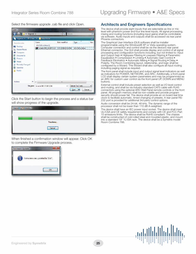
Select the firmware upgrade .cab file and click Open.
Click the Start button to begin the process and a status bar will show progress of the upgrade.
When finished a confirmation window will appear. Click OK to complete the Firmware Upgrade process.
Architects and Engineers SpecificationsThe device shall provide eight inputs that are selectable as line or mic level with phantom power and four line level inputs. All signal processing, mixing and routing functions (including input gains) shall be controllable via software. Audio inputs and outputs shall be accessed via rear panel Phoenix connectors.The Graphical User Interface (GUI) software shall be installer programmableusingtheWindows®XPorVistaoperatingsystem.Computer connection and control shall be via the device’s rear panel Ethernet connector. The GUI shall provide display and control of all signal processing and configuration functions including, but not limited to: Input andOutputGain•HighpassFiltering•LowpassFiltering•ParametricEqualization•Compression•Limiting•AutomaticGainControl•FeedbackElimination•AutomaticMixing•SignalRouting•Delay•Polarity. The Room Combining layout, relationship, and logic shall be configured by a Wizard. This Wizard shall also configure all input routing including paging signal as required.The front panel shall include input and output signal level indicators as well asindicatorsforPOWER,NETWORK,andARC.Additionally,afrontpanelLCDshalldisplaycertainsystemparametersandmaybeprogrammedasanARCforcustomusercontrolviathefrontpanelUP,DOWNandMENUbuttons.External control shall include preset selection as well as I/O level control and muting, and shall be via industry-standard CAT5 cable with RJ45 connectors using the optional ARC Wall Panel remote controls or the front panel. All program memory shall be non-volatile and provide program security should power fail. The device shall provide an on board real time clock to facilitate automatic, timed changing of presets. A rear panel RS-232 port is provided for additional 3rd party control options.Audio conversion shall be 24-bit, 48 kHz. The dynamic range of the processorshallnotbelowerthan110dBA-weighted.The device shall have an IEC power input socket. The device shall meet UL/CSAandCEsafetyrequirementsandcomplywithCEandFCCPart15 emissions limits. The device shall be RoHS compliant. The chassis shall be constructed of cold rolled steel and moulded plastic, and mount into a standard 19” 1U EIA rack. The device shall be a Symetrix model Room Combine 788.
UpgradingFirmware•A&ESpecs

26
Quick Start Guide
6408 216th Street SW | Mountlake Terrace, WA 98043 USA
T +1.425.778.7728 F +1.425.778.7727 | www.SymetrixAudio.com
Declaration of Conformity
We, Symetrix Incorporated, 6408 216th St. SW, MountlakeTerrace,Washington,USA,declareunderoursole
responsibility that the product:
Room Combine 788
to which this declaration relates, is in conformity with the following standards:
UL 60065, cUL 60065, IEC 60065, EN 55103-1, EN 55103-2, FCC Part 15 compliant
The technical construction file is maintained at:
Symetrix, Inc.
6408 216th St. SW
MountlakeTerrace,WA,98043USA
The authorized representative located within the European Community is:
World Marketing Associates
P.O.Box100
St.Austell,Cornwall,PL266YU,U.K.
Dateofissue:May31,2009
Placeofissue:MountlakeTerrace,Washington,USA
Authorized signature:
DaneButcher,President,Symetrix Incorporated.
Declaration of Conformity

27
Integrator Series Room Combine 788
The Symetrix Limited WarrantySymetrix, Inc. expressly warrants that the product will be free from defects in material and workmanship for two (2) years from the date the product is shipped from the factory. Symetrix’s obligations under this warranty will be limited to repairing or replacing, at Symetrix’s option, the part or parts of the product which prove defective in material or workmanship within two (2) years from the date the product is shipped fromthefactory,providedthattheBuyergivesSymetrixpromptnoticeof any defect or failure and satisfactory proof thereof. Products may be returnedbyBuyeronlyafteraReturnAuthorizationnumber(RA)hasbeenobtainedfromSymetrix.Buyerwillprepayallfreightchargestoreturn the product to the Symetrix factory. Symetrix reserves the right to inspect any products which may be the subject of any warranty claim before repair or replacement is carried out. Symetrix may, at its option, require proof of the original date of purchase (dated copy of original retail dealer’s invoice). Final determination of warranty coverage lies solely with Symetrix. Products repaired under warranty will be returned freight prepaid via United Parcel Service by Symetrix, to any location within the Continental United States. Outside the Continental United States, products will be returned freight collect.
The foregoing warranties are in lieu of all other warranties, whether oral, written, express, implied or statutory. Symetrix, Inc. expressly disclaims any IMPLIED warranties, including fitness for a particular purpose or merchantability. Symetrix’s warranty obligation and buyer’s remedies hereunder are SOLELY and exclusively as stated herein.
This Symetrix product is designed and manufactured for use in professional and studio audio systems and is not intended for other usage. With respect to products purchased by consumers for personal, family, or household use, Symetrix expressly disclaims all implied warranties, including but not limited to warranties of merchantability and fitness for a particular purpose.
This limited warranty, with all terms, conditions and disclaimers set forth herein, shall extend to the original purchaser and anyone who purchases the product within the specified warranty period.
Symetrix does not authorize any third party, including any dealer or sales representative, to assume any liability or make any additional warranties or representation regarding this product information on behalf of Symetrix.
This limited warranty gives the buyer certain rights. You may have additional rights provided by applicable law.
Note: Some Symetrix products contain embedded software and may also be accompanied by control software intended to be run on a personal computer. Said software is specifically excluded from this warranty.
Limitation of LiabilityThe total liability of Symetrix on any claim, whether in contract, tort (including negligence) or otherwise arising out of, connected with, or resulting from the manufacture, sale, delivery, resale, repair, replacement or use of any product will not exceed the price allocatable to the product or any part thereof which gives rise to the claim. In no event will Symetrix be liable for any incidental or consequential damages including but not limited to damage for loss of revenue, cost of capital, claims of customers for service interruptions or failure to supply, and costs and expenses incurred in connection with labor, overhead, transportation, installation or removal of products, substitute facilities or supply houses.
Servicing Your Symetrix ProductIf you have determined that your Symetrix product requires repair services and you live outside of the United States please contact your local Symetrix dealer or distributor for instructions on how to obtain service. If you reside in the U.S. then proceed as follows:
Return AuthorizationAt the Symetrix factory, Symetrix will perform in-warranty or out-of-warranty service on any product it has manufactured for a period of three (3) years from date of discontinued manufacture.
BeforesendinganythingtoSymetrix,pleasecontactourCustomerService Department for a Return Authorization (RA) number. The telephone number is +1.425.778.7728. Additionally, support is available via the web site: http://support.SymetrixAudio.com.
In-warranty RepairsTo get your Symetrix product repaired under the terms of the warranty:
1. Call us for an RA number (have the serial number, shipping and contact information and description of the problem ready).
2. Pack the unit in its original packaging materials.
3. Include your name, address, daytime telephone number, and a brief statement of the problem.
4. Write the RA number on the outside of the box.
5. Ship the unit to Symetrix, freight prepaid. We do not accept freight collect shipments.
Just do these five things, and repairs made in-warranty will cost you only one-way freight charges. We’ll pay the return freight. If you do not have the factory packaging materials, we recommend using an oversize box. Wrap the unit in a plastic bag, surround it with bubble-wrap, and placeitintheboxsurroundedbyStyrofoampeanuts.Besurethereisenough clearance in the box to protect the rack ears. We won’t return the unit in anything but Symetrix packaging for which there will be a nominal charge. If the problem is due to operator misuse or error, charges for parts and/or labor may be applied. In any event, if there are charges for the repair, you will pay for the return freight. All billing must be prearranged at the time the RA is issued unless you have made other arrangements. Repaired units will not be returned until payment terms havebeenarranged.SYMETRIXWILLNOTBERESPONSIBLEFORREPAIREDUNITSLEFTUNPAIDMORETHAN60DAYSFROMDATEOFREPAIR.UNITSLEFTMORETHAN60DAYSMAY,WILLBECOMETHEPROPERTYOFSYMETRIX,INC..
Out-of-warranty RepairsIf the warranty period has passed, you’ll be billed for all necessary parts, labor, packaging materials, and freight charges. Please remember, you must call for an RA number before sending the unit to Symetrix.
Warranty and Service

ItemNo.53-0040
Room Combine 788 Quick Start Guide
© 2009 Symetrix, Inc. All rights reserved. Printed in the United States of America. The information in this document is subject to change without notice. Symetrix,Inc.shallnotbeliablefortechnicaloreditorialerrorsoromissionscontainedherein;norisitliableforincidentalorconsequentialdamagesresultingfromthefurnishing,performance,oruseofthismaterial.Mentionofthird-partyproductsisforinformationalpurposesonlyandconstitutesneither an endorsement nor a recommendation. Symetrix assumes no responsibility with regard to the performance or use of these products. Under copyright laws, no part of this brochure may be reproduced or transmitted in any form or by any means, electronic or mechanical, without permission in writing from Symetrix, Inc. If, however, your only means of access is electronic, permission to print one copy is hereby granted. The following are eitherTrademarksorRegisteredTrademarksofSymetrix,Inc.:Symetrix,SymNet,SymNetDesigner,SymLinkandCobraLink.WindowsisaRegisteredTrademarkofMicrosoft,Inc..Otherproduct names mentioned herein may be trademarks and/or registered trademarks of other companies and are property of their respective owners.
6408 216th Street SW | Mountlake Terrace, WA 98043 USA
T +1.425.778.7728 F +1.425.778.7727 | www.SymetrixAudio.com


![IS 788 8.11 IS 788 [Process] Change Management Lecture: Process Redesign Methodologies.](https://static.fdocuments.in/doc/165x107/56649d375503460f94a0f429/is-788-811-is-788-process-change-management-lecture-process-redesign.jpg)