Integration Spatial Processing the WINNER … · Integration ofSpatial Processinginthe ......
5
Integration of Spatial Processing in the WINNER B3G Air Interface Design Martin D6ttling', Mikael Sternad2, Goran Klang3, J6rn von Hafen', Magnus Olsson3 1: Siemens AG, Muinchen, Germany, E-mail: {Martin.Doettling, Joern.von Haefen} isiemens.com 2: Signals and Systems, Uppsala University, Uppsala, Sweden, E-mail: Mikael.Sternad gsignal.uu.se 3: Ericsson AB, Stockholm, Sweden, E-mail: {Goran.N.Klang, Magnus.A.Olsson}j ericsson.com Abstract- Numerous investigations of spatial processing algo- rithms are available in literature showing the benefit of MIMO systems in particular situations. From a system perspective, however, spatial processing has to provide adaptivity and scal- ability to a wide range of scenarios and has also to be seen in the context of its impact on other system services and functions, its enabling requirements, overhead, and robustness. This paper summarizes recent work towards integrated spatial processing services and functions for an OFDM-based B3G air interface, developed in the European IST research project WINNER. The current status of the air interface and the multi- user spatial domain link adaptation concept is summarized. A baseline spatial scheme selection process is developed as part of the overall MAC radio resource control. Keywords-WINNER, spatial processing, radio resource control, OFDM, MIMO I. INTRODUCTION The European research project WINNER is a cooperation of 38 partners from industry, operators, and academia which is partly funded by the European Union, with the overall goal to develop a single radio interface covering the full range from isolated hot spots to wide area cellular scenarios by using different modes of a common technology [1]. It targets increased data rates, low latency, and high system capacity based on adaptive transmission schemes, flexible spectrum usage, relaying, and advanced multi-antenna processing. Spatial processing is a key enabler to meet these targets, since it provides an additional dimension of multiplexing, multiple access, and link adaptation. It also allows implement- ing enhanced (multi-user) interference management techniques. Depending on the specific needs of the data flows, robustness, coverage, or data rate can be increased and high overall spec- tral efficiency can be achieved. Due to the manifold usage scenarios to be accommodated, the WINNER multi-antenna architecture must be able to foster gains due to spatial diversity, spatial multiplexing, SDMA, beamforming, and spatial interference management in flexible combinations and with scalable amount of channel knowledge at the transmitter. We distinguish open-loop techniques, where no channel knowledge is available at the transmitter, from cases where we have a channel quality indicator (CQI, e.g., knowledge of SINR) or more complete channel state information (CSI, e.g. channel covariance matrix), either as long-term or short-term informa- tion. Such a scalable and adaptive concept is achieved by a multi-user spatial domain link adaptation concept, based on (linear) dispersion codes, beamforming, multi-user precoding, and per stream rate control (PSRC) [2]. The actual configuration and parameterization of the spatial processing is part of the MAC service radio resource control, which splits the available resources across cells and transport channels, and performs fast resource scheduling. The multiple functionalities of this service are interconnected and a joint optimization is not tractable. Even an iterative solution would compromise the quest for low latency. Therefore this paper outlines a baseline non-iterative procedure and split into func- tionalities that allows a flexible and channel-dependent resource assignment including spatial processing. After a brief outline of the WINNER air interface in Section II, a generic processing architecture for the multi- antenna processing is sketched in Section III. A simple baseline spatial scheme selection algorithm as part of the radio resource control is introduced in Section IV. Finally, conclusions are provided in Section V. II. THE WINNER AIR INTERFACE This section gives a brief outline of the current working assumptions (which of course still are subject to permanent changes and refinement in the ongoing project) for the WINNER air interface as far as they are related to spatial proc- essing, see [3] for more details on the overall air interface. The WINNER air interface is a packet-oriented user-centric concept based on OFDM in downlink and Generalised Multi-Carrier (GMC) transmission (i.e. a generic frequency-domain signal generation with appropriate precoding) in uplink. FDD and TDD-based physical layer modes (PLM) are considered. The basic resource and link adaptation units are called chunks, and consist of a contiguous set of nsub subcarriers and nsymb symbols, according to coherence bandwidth and time. In the FDD mode one chunk contains 96 symbols and spans 312.5 kHz x 345.6 his. For the TDD mode each chunk contains 80 symbols (781.2 kHz x 108.8 his). Spatial processing (e.g. by SDMA or spatial multiplexing) allows re-use of each time- frequency chunk, i.e. Q, chunk layers are available for chunk c (cf. Figure 1). A frame of 691.2 pts duration contains 6 slots (configurable for UL/DL) for TDD and two slots for FDD. While the base stations operate in full duplex FDD mode, half- duplex FDD terminals are also supported. 0-7803-9392-9/06/$20.00 (c) 2006 IEEE 246
Transcript of Integration Spatial Processing the WINNER … · Integration ofSpatial Processinginthe ......
Integration of Spatial Processing in theWINNER B3G Air Interface Design
Martin D6ttling', Mikael Sternad2, Goran Klang3, J6rn von Hafen', Magnus Olsson3
1: Siemens AG, Muinchen, Germany, E-mail: {Martin.Doettling, Joern.von Haefen} isiemens.com2: Signals and Systems, Uppsala University, Uppsala, Sweden, E-mail: Mikael.Sternad gsignal.uu.se
3: Ericsson AB, Stockholm, Sweden, E-mail: {Goran.N.Klang, Magnus.A.Olsson}j ericsson.com
Abstract- Numerous investigations of spatial processing algo-rithms are available in literature showing the benefit of MIMOsystems in particular situations. From a system perspective,however, spatial processing has to provide adaptivity and scal-ability to a wide range of scenarios and has also to be seen in thecontext of its impact on other system services and functions, itsenabling requirements, overhead, and robustness.
This paper summarizes recent work towards integrated spatialprocessing services and functions for an OFDM-based B3G airinterface, developed in the European IST research projectWINNER. The current status of the air interface and the multi-user spatial domain link adaptation concept is summarized. Abaseline spatial scheme selection process is developed as part ofthe overall MAC radio resource control.
Keywords-WINNER, spatial processing, radio resource control,OFDM, MIMO
I. INTRODUCTIONThe European research project WINNER is a cooperation
of 38 partners from industry, operators, and academia which ispartly funded by the European Union, with the overall goal todevelop a single radio interface covering the full range fromisolated hot spots to wide area cellular scenarios by usingdifferent modes of a common technology [1]. It targetsincreased data rates, low latency, and high system capacitybased on adaptive transmission schemes, flexible spectrumusage, relaying, and advanced multi-antenna processing.
Spatial processing is a key enabler to meet these targets,since it provides an additional dimension of multiplexing,multiple access, and link adaptation. It also allows implement-ing enhanced (multi-user) interference management techniques.Depending on the specific needs of the data flows, robustness,coverage, or data rate can be increased and high overall spec-tral efficiency can be achieved. Due to the manifold usagescenarios to be accommodated, the WINNER multi-antennaarchitecture must be able to foster gains due to spatial diversity,spatial multiplexing, SDMA, beamforming, and spatialinterference management in flexible combinations and withscalable amount of channel knowledge at the transmitter. Wedistinguish open-loop techniques, where no channel knowledgeis available at the transmitter, from cases where we have achannel quality indicator (CQI, e.g., knowledge of SINR) ormore complete channel state information (CSI, e.g. channelcovariance matrix), either as long-term or short-term informa-
tion. Such a scalable and adaptive concept is achieved by amulti-user spatial domain link adaptation concept, based on(linear) dispersion codes, beamforming, multi-user precoding,and per stream rate control (PSRC) [2].
The actual configuration and parameterization of the spatialprocessing is part of the MAC service radio resource control,which splits the available resources across cells and transportchannels, and performs fast resource scheduling. The multiplefunctionalities of this service are interconnected and a jointoptimization is not tractable. Even an iterative solution wouldcompromise the quest for low latency. Therefore this paperoutlines a baseline non-iterative procedure and split into func-tionalities that allows a flexible and channel-dependentresource assignment including spatial processing.
After a brief outline of the WINNER air interface inSection II, a generic processing architecture for the multi-antenna processing is sketched in Section III. A simple baselinespatial scheme selection algorithm as part of the radio resourcecontrol is introduced in Section IV. Finally, conclusions areprovided in Section V.
II. THE WINNER AIR INTERFACEThis section gives a brief outline of the current working
assumptions (which of course still are subject to permanentchanges and refinement in the ongoing project) for theWINNER air interface as far as they are related to spatial proc-essing, see [3] for more details on the overall air interface. TheWINNER air interface is a packet-oriented user-centric conceptbased on OFDM in downlink and Generalised Multi-Carrier(GMC) transmission (i.e. a generic frequency-domain signalgeneration with appropriate precoding) in uplink. FDD andTDD-based physical layer modes (PLM) are considered.
The basic resource and link adaptation units are calledchunks, and consist of a contiguous set of nsub subcarriers andnsymb symbols, according to coherence bandwidth and time. Inthe FDD mode one chunk contains 96 symbols and spans312.5 kHz x 345.6 his. For the TDD mode each chunk contains80 symbols (781.2 kHz x 108.8 his). Spatial processing (e.g. bySDMA or spatial multiplexing) allows re-use of each time-frequency chunk, i.e. Q, chunk layers are available for chunk c(cf. Figure 1). A frame of 691.2 pts duration contains 6 slots(configurable for UL/DL) for TDD and two slots for FDD.While the base stations operate in full duplex FDD mode, half-duplex FDD terminals are also supported.
0-7803-9392-9/06/$20.00 (c) 2006 IEEE246
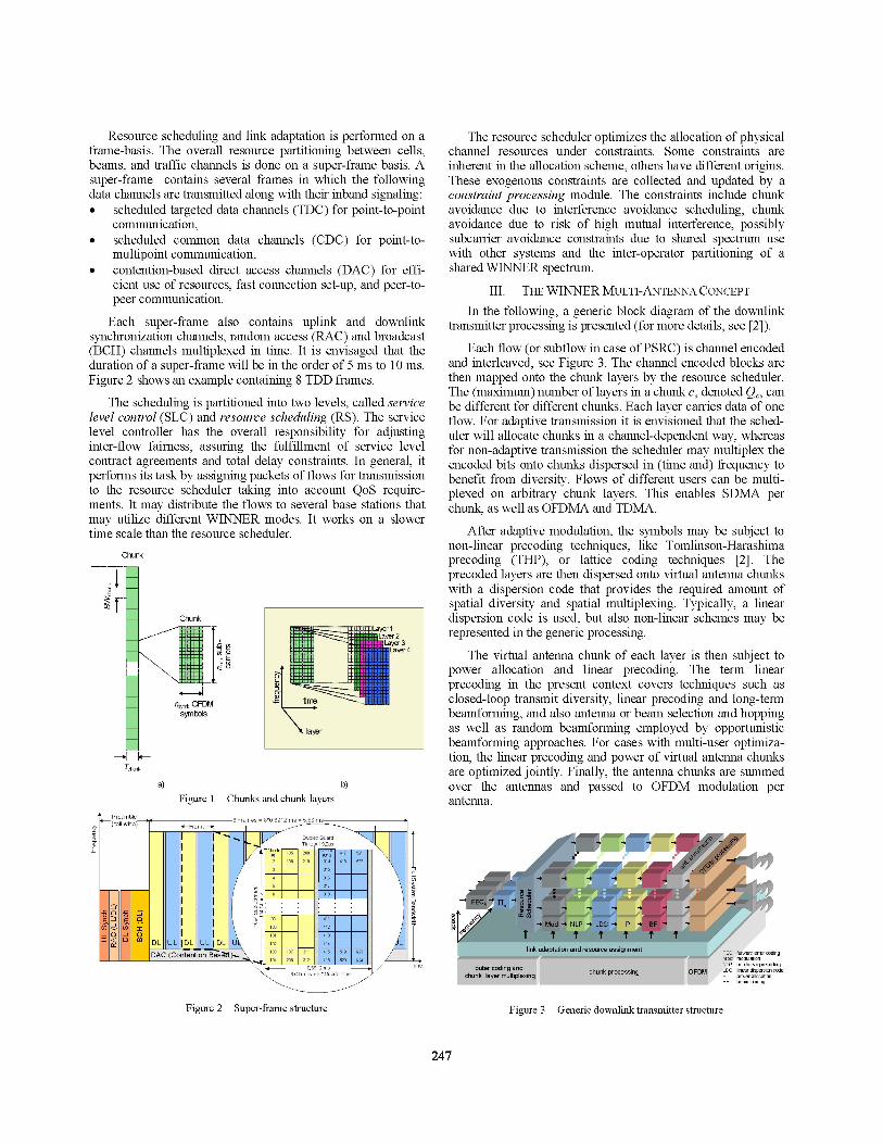
Resource scheduling and link adaptation is performed on aframe-basis. The overall resource partitioning between cells,beams, and traffic channels is done on a super-frame basis. Asuper-frame contains several frames in which the followingdata channels are transmitted along with their inband signaling:* scheduled targeted data channels (TDC) for point-to-point
communication,* scheduled common data channels (CDC) for point-to-
multipoint communication,* contention-based direct access channels (DAC) for effi-
cient use of resources, fast connection set-up, and peer-to-peer communication.
Each super-frame also contains uplink and downlinksynchronization channels, random access (RAC) and broadcast(BCH) channels multiplexed in time. It is envisaged that theduration of a super-frame will be in the order of 5 ms to 10 ms.Figure 2 shows an example containing 8 TDD frames.
The scheduling is partitioned into two levels, called servicelevel control (SLC) and resource scheduling (RS). The servicelevel controller has the overall responsibility for adjustinginter-flow fairness, assuring the fulfillment of service levelcontract agreements and total delay constraints. In general, itperforms its task by assigning packets of flows for transmissionto the resource scheduler taking into account QoS require-ments. It may distribute the flows to several base stations thatmay utilize different WINNER modes. It works on a slowertime scale than the resource scheduler.
Chunk
......
Chunk..... .1 i - -
I.. .._,n cn
U.M. z.Pill $,
n,ym OFDMsymbol
a) b)Figure 1 Chunks and chunk layers
The resource scheduler optimizes the allocation of physicalchannel resources under constraints. Some constraints areinherent in the allocation scheme, others have different origins.These exogenous constraints are collected and updated by aconstraint processing module. The constraints include chunkavoidance due to interference avoidance scheduling, chunkavoidance due to risk of high mutual interference, possiblysubcarrier avoidance constraints due to shared spectrum usewith other systems and the inter-operator partitioning of ashared WINNER spectrum.
III. THE WINNER MULTI-ANTENNA CONCEPTIn the following, a generic block diagram of the downlink
transmitter processing is presented (for more details, see [2]).
Each flow (or subflow in case of PSRC) is channel encodedand interleaved, see Figure 3. The channel encoded blocks arethen mapped onto the chunk layers by the resource scheduler.The (maximum) number of layers in a chunk c, denoted Q, canbe different for different chunks. Each layer carries data of oneflow. For adaptive transmission it is envisioned that the sched-uler will allocate chunks in a channel-dependent way, whereasfor non-adaptive transmission the scheduler may multiplex theencoded bits onto chunks dispersed in (time and) frequency tobenefit from diversity. Flows of different users can be multi-plexed on arbitrary chunk layers. This enables SDMA perchunk, as well as OFDMA and TDMA.
After adaptive modulation, the symbols may be subject tonon-linear precoding techniques, like Tomlinson-Harashimaprecoding (THP), or lattice coding techniques [2]. Theprecoded layers are then dispersed onto virtual antenna chunkswith a dispersion code that provides the required amount ofspatial diversity and spatial multiplexing. Typically, a lineardispersion code is used, but also non-linear schemes may berepresented in the generic processing.
The virtual antenna chunk of each layer is then subject topower allocation and linear precoding. The term linearprecoding in the present context covers techniques such asclosed-loop transmit diversity, linear precoding and long-termbeamforming, and also antenna or beam selection and hoppingas well as random beamforming employed by opportunisticbeamforming approaches. For cases with multi-user optimiza-tion, the linear precoding and power of virtual antenna chunksare optimized jointly. Finally, the antenna chunks are summedover the antennas and passed to OFDM modulation perantenna.
........................ #- momulationNLP: n-linr pr dingouter coding and fPl D~I~i~doUtdddihknrceshd F LDC: lineardispersioncode
Figure 2 Super-frame structure Figure 3 Generic downlink transmitter structure
247
.0T.h.unk
Depending on the scenario, system load, the propagationconditions, and the transport channel type (unicast, multicast orbroadcast), varying spatial processing gains (like spatialmultiplexing, spatial diversity, beamforming, and interferencemanagement) will be exploited to different degrees. Therefore,different spatial schemes will be applied. Typicall, in aparticular spatial scheme not all function blocks of the genericframework will be operational.
IV. SPATIAL SCHEME SELECTION AND RADIO RESOURCECONTROL
Radio resource control involves the following basic stepsand it operates on two time scales:* with super-frame granularity:
* Resource partitioning: The distribution of the totalradio resources to different transport channels isadjusted on this time scale, based on the aggregateddemand within each transport channel. Guard chunksfor interference avoidance scheduling are alsodefined and re-adjusted, to enable flexible spectrumuse between WINNER operators/users and adaptiveinterference avoidance between neighbouring cells,sectors, and beams.
* Spatial scheme selection: Based on various decisioncriteria, the spatial processing algorithm for eachflow is determined, i.e., the overall configuration ofthe physical layer blocks is determined.
* with frame granularity:* Resource scheduling: The scheduled flows are allo-
cated to space-time-frequency resources availablewithin the super-frame.
* Link Adaptation including traditional and (multi-user)spatial link adaptation. In this step the actualparameters of the physical layer blocks are deter-mined.
A. Resource PartitioningResource partitioning would in principle require knowledge
of the capacity of each chunk realized by the actual subsequentresource allocation process, which depends on the flow allo-cated, the spatial scheme selected, and the link adaptation. Inorder to avoid highly complex and iterative algorithms, theresource partitioning can be based on evaluation of the aggre-gated capacity of all flows from the last superframes. Fromthis, the average capacity per transport channel and radioresource can be estimated. A control loop can then adjust theresource partitioning to ensure that the requirements of eachtransport channel are met and account for all effects thatdetermine the chunk capacity implicitly.
B. Spatial Scheme SelectionSpatial scheme selection per flow must be based on infor-
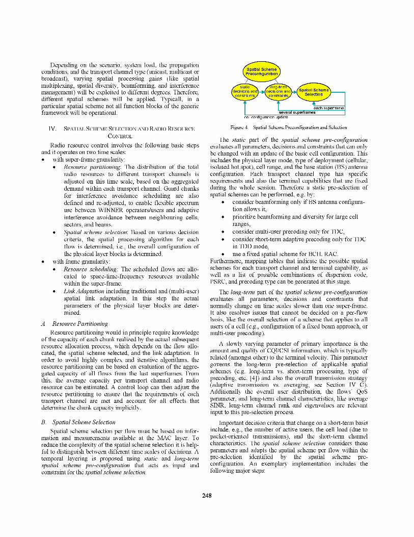
mation and measurements available at the MAC layer. Toreduce the complexity of the spatial scheme selection it is help-ful to distinguish between different time scales of decisions. Atemporal layering is proposed using static and long-termspatial scheme pre-configuration that acts as input andconstraint for the spatial scheme selection.
severalcell configuration update
superfame
Figure 4 Spatial Scheme Preconfiguration and Selection
The static part of the spatial scheme pre-configurationevaluates all parameters, decisions and constraints that can onlybe changed with an update of the basic cell configuration. Thisincludes the physical layer mode, type of deployment (cellular,isolated hot spot), cell range, and the base station (BS) antennaconfiguration. Each transport channel type has specificrequirements and also the terminal capabilities that are fixedduring the whole session. Therefore a static pre-selection ofspatial schemes can be performed, e.g. by:
* consider beamforming only ifBS antenna configura-tion allows it,
* prioritize beamforming and diversity for large cellranges,
* consider multi-user precoding only for TDC,* consider short-term adaptive precoding only for TDC
in TDD mode,* use a fixed spatial scheme for BCH, RAC.
Furthermore, mapping tables that indicate the possible spatialschemes for each transport channel and terminal capability, aswell as a list of possible combinations of dispersion code,PSRC, and precoding type can be generated at this stage.
The long-term part of the spatial scheme pre-configurationevaluates all parameters, decisions and constraints thatnormally change on time scales slower than one super-frame.It also resolves issues that cannot be decided on a per-flowbasis, like the overall selection of a scheme that applies to allusers of a cell (e.g., configuration of a fixed beam approach, ormulti-user precoding).A slowly varying parameter of primary importance is the
amount and quality of CQI/CSI information, which is typicallyrelated (amongst other) to the terminal velocity. This parametergoverns the long-term pre-selection of applicable spatialschemes (e.g. long-term vs. short-term processing, type ofprecoding, etc. [4]) and also the overall transmission strategy(adaptive transmission vs. averaging, see Section IV C).Additionally the overall user distribution, the flows' QoSparameter, and long-term channel characteristics, like averageSINR, long-term channel rank and eigenvalues are relevantinput to this pre-selection process.
Important decision criteria that change on a short-term basisinclude, e.g., the number of active users, the cell load (due topacket-oriented transmissions), and the short-term channelcharacteristics. The spatial scheme selection considers theseparameters and adapts the spatial scheme per flow within thepre-selection identified by the spatial scheme pre-configuration. An exemplary implementation includes thefollowing major steps:
248
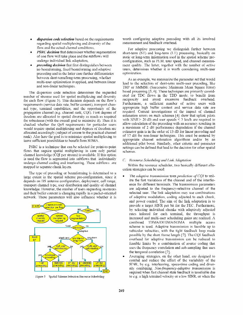
* dispersion code selection based on the requirementsregarding spatial multiplexing and diversity of theflow and the actual channel conditions,
* PSRC decision that determines whether segmentationof one flow will take place and the subflows willundergo individual link adaptation,
* precoding decision that first distinguishes betweenno beamforming, fixed beamforming and adaptiveprecoding and in the latter case further differentiatesbetween short-term/long-term processing, whethermulti-user optimisation is applied, and between linearand non-linear techniques.
The dispersion code selection determines the requestednumber of streams used for spatial multiplexing and diversityfor each flow (Figure 5). This decision depends on the flow'srequirements (service data rate, buffer content), transport chan-nel type, terminal capabilities, and the opportunity of thepropagation channel (e.g. channel rank, CQI). First degrees offreedom are allocated to spatial diversity as much as requiredfor robustness (with the overall goal to minimize it). Then it ischecked whether the QoS requirements for particular userswould require spatial multiplexing and degrees of freedom areallocated accordingly (subject of course to the practical channelrank). Also here the goal is to minimize spatial multiplexing toleave sufficient possibilities to benefit from SDMA.
PSRC is a technique that can be selected for point-to-pointflows that require spatial multiplexing in case only partialchannel knowledge (CQI per stream) is available. If this optionis used the flow is segmented into subflows that individuallyundergo channel coding and interleaving. These subflows aremapped to separate chunk layers.
The type of precoding or beamforming is determined to alarge extent in the spatial scheme pre-configuration, since itdepends on BS antenna configuration, deployment, cell range,transport channel type, user distribution and quality of channelknowledge. However, the number of users requesting resourcesand their buffer content is changing rapidly in a packet-orientednetwork. These parameters will also influence whether it is
ae~ j no
(fixed nor_coi
adaptive
fixed short term ort-term! long-termBF long-termn
yes ulti-user\ no yes m eulti us nooptimisation imisat
yes non-linea norcodin
THP SMMSE ST-SU TSMMSE LTTSUprecoding precoding precoding precoding precoding
Figure 5 Spatial Scheme Selection Resource Scheduling
worth configuring adaptive precoding with all its involvedmeasurement and feedback overhead.
For adaptive processing we distinguish further betweenshort-term (ST) and long-term (LT) processing, basically onstatic or long-term information used in the spatial scheme pre-configuration, such as PLM, user speed, and channel measure-ment quality. The latter, together with the number of activeusers, determines whether it is worth considering multi-useroptimization.
As an example, we summarize the parameter set that wouldlead to the selection of short-term multi-user precoding, likeTHP or SMMSE (Successive Minimum Mean Square Error)based processing [5, 6]. These techniques are primarily consid-ered for TDC flows in the TDD mode, to benefit fromreciprocity and avoid excessive feedback overhead.Furthermore, a sufficient number of active users withappropriate high buffer content and service data rate arerequired. Current investigations of the impact of channelestimation errors on such schemes [4] show that uplink pilotswith SINR > 20 dB and user speeds < 3 km/h are required toallow calculation of the precoding with an accuracy resulting ina maximum of 2 dB performance degradation if the channelestimator gain is in the order of 13 dB for linear precoding andof 17 dB for non-linear techniques. This must be ensured byappropriate channel estimation algorithms and/or by anadditional pilot boost. Similarly, other criteria and parametersettings can be defined that lead to the decision for other spatialschemes.
C. Resource Scheduling and Link AdaptationWithin the resource scheduler, two basically different allo-
cation strategies can be used:
* The adaptive transmission uses prediction ofCQI to util-ize the fast variations of the channel and of the interfer-ence for different terminals. The transmission parametersare adjusted to the frequency-selective channel of theselected user. The link adaptation may use combinationsof adaptive modulation, coding adjusted to each chunk,and power control. The aim of the link adaptation is toprovide a target SINR per bit for the FEC. Furthermore,by selecting individual chunks with adaptively adjustedrates tailored for each terminal, the throughput isincreased and multi-user scheduling gains are realized. Acombined TDMA/OFDMA/SDMA multiple accessscheme is used. Adaptive transmission is feasible up tovehicular velocities, with the tight feedback loop madepossible by the short frame length [7]. The CQI feedbackoverhead for adaptive transmission can be reduced tofeasible limits by a combination of source coding thatuses the frequency correlation and sub-sampling that usesthe temporal correlation [7].
* Averaging strategies, on the other hand, are designed tocombat and reduce the effect of the variability of theSINR, by e.g. interleaving, space-time coding and diver-sity combining. Non-frequency-adaptive transmission isrequired when fast channel state feedback is unreliable dueto e.g. a high terminal velocity or a low SINR, or when the
249

terminal does not support the adaptive transmission. Non-frequency-adaptive transmission is also mostly requiredfor point-to-multipoint communication belonging to thecommon data channel (CDC) flows. Non-frequency-adap-tive transmission requires the FEC blocks to be mapped ona set of chunks that are widely dispersed in frequency or indifferent spatial channels to maximize diversity. The termnon-frequency-adaptive transmission here also includestransmission that slowly adapts to the shadow fading, butaverages over the frequency selective (fast) fading. Chunk-based TDMA/OFDMA would not provide sufficientdiversity for small packets, therefore, either TDMA perOFDM symbol, OFDMA per subcarrier, or MC-CDMAare under consideration. All of them can be combined withan SDMA component.
A fundamental issue when designing such a resourcescheduling and multiple access scheme, is how the schedulershould separate and group the users to realize SDMA. Thesimplest form of SDMA is traditional sectorisation, where thecoverage area of a site is physically split into a number ofsectors and the users in each sector are separated by time- andfrequency resources. To derive the SDMA decision in a moregeneral framework, the idea is to assign the different flows intodifferent sets that include highly interfering flows within oneset and guarantee an upper limit of interference across sets.Once such sets are established, we can use SDMA for flows ofdifferent sets, and other multiple access schemes (such asTDMA, FDMA) within one set [3].
Different basic algorithms apply depending on the amountof channel knowledge at the transmitter. If only a channelquality indicator (CQI) is available, so-called opportunistic orgrid-of-beams beamforming approaches can be used. Here,sufficient interference suppression across beams is a priorigiven due to the proper design of the beams concurrently used.Therefore the pre-defined fixed beams are already the sets weare looking for.
If CSI is available at the transmitter and adaptive precodingis applied, the spatial sets can be generated by calculating themutual correlation between users [8, 9]. These methods areapplied per chunk for frequency-adaptive flows and once overthe whole allocation for non-frequency-adaptive flows. Firstthe eigenvectors of all flows and the corresponding multi-usercorrelation matrix are calculated. For each flow, only the kstrongest eigenvectors should be used, according to therequested number of spatial streams (determined by the disper-sion code selection or the PSRC decision). Then the flows aredivided into groups with correlation higher than a pre-definedthreshold. SDMA can now be performed for flows in differentsets, whereas TDMA or FDMA has to be used for flows withinone set.
Once these sets have been determined, the SDMA decisionmust be integrated in the overall resource allocation process,i.e. the decision must integrate the priorities due to QoScontracts and the opportunities and constraints due to thespatial channel characteristics. In particular it might be useful
to revise the dispersion code selection (i.e. the requestednumber of spatial streams for spatial multiplexing and diversityper flow) in order to improve the opportunities for SDMA andto optimize the cell throughput. A successive allocation of thespatial degrees of freedom based on maximum increments of atarget function is a promising candidate. Traditionally purechannel-dependent criteria have been used, such as maximumincrements of sum-rate [10], however the target functionshould also take priorities into account.
V. CONCLUSIONS
This paper summarizes recent work towards integratedspatial processing services and functions for an OFDM-basedB3G air interface, developed in the European IST researchproject WINNER. The current status of the air interface and themulti-user spatial domain link adaptation concept is summa-rized. A baseline spatial scheme selection process with tempo-ral layering is developed as part of the overall NIAC radioresource control. Relevant measurements and decision criteriafor spatial scheme selection are discussed.
ACKNOWLEDGMENTThis work has been performed in the framework of the IST
project IST-2003-507581 WINNER, which is partly funded bythe European Union [and for Swiss partners the SwissGovernment]. The authors would like to acknowledge thecontributions of their colleagues.
REFERENCES[1] WINNER, Wireless World Initiative New Radio,[2] M. Dottling, D. Astely, and M. Olsson, "A Multi-User Spatial Domain
Link Adaptation Concept for Beyond 3G Systems," Proc.PIMRC 2005,Berlin, Germany, September 2005.
[3] IST-2003-507581 WINNER, "D2.10 Final report on identified RI keytechnologies, system concept, and their assessment", December, 2005.
[4] IST-2003-507581 WINNER, "D2.7 Assessment of AdvancedBeamforming and MIMO Technologies", February 2005.
[5] D. Wang, E.A. Jorswieck, A. Sezgin, and E. Costa, "Joint Tomlinson-Harashima precoding with orthogonal space time block codes for multi-user MIMO OFDM systems", in Proc. IEEE Vehicular TechnologyConf. VTC 2005 Spring, Stockholm, Sweden, June 2005.
[6] V. Stankovic and M. Haardt, "Multi-user MIMO downlink precoding forusers with multiple antennas", in Proc. of the 12th Meeting of theWireless World Research Forum (WWRF), Toronto, ON, Canada, Nov.2004.
[7] IST-2003-507581 WINNER, "D2.4 Assessment of adaptivetransmission technologies", February, 2005.
[8] Del Galdo G., Haardt M., "Comparison of zero-forcing methods fordownlink spatial multiplexing in realistic multi-user MIMO channels",in Proc. 59th IEEE Vehicular Technology Conf (VTC 2004 Spring),(Milan, Italy), May 2004.
[9] Zhang Y.J., Letaief K.B., "An Efficient Resource-Allocation Scheme forSpatial Multiuser Access in MIMO/OFDM Systems", in IEEE Trans.Comm., vol. 53, no. 1, Jan. 2005, pp. 107-116.
[10] P. Tejera, W. Utschick, G. Bauch, and J.A. Nossek, "Sum-RateMaximizing Decomposition Approaches for Multiuser MIMO-OFDM,"Proc.PIMRC 2005, Berlin, Germany, September 2005.
250