Integration of Specular Reflector in a Dual Axis Solar Tracker
9
Integration of Specular Reflector in a Dual Axis Solar Tracker Teofrenz Ycot, John Vincent Tiansing, Michaela Aliganga, Rachel Chong and Jun-Jun Obiso Cebu Institute of Technology-University [email protected] Abstract Installation of solar panels on rooftops has increased in popularity. Energy conversion is inefficient because solar panels are not always perpendicular to the sun. This problem is addressed by designing a low cost dual axis solar tracker with specular reflector. This tracker moves the panel and reflector assembly in a controlled manner. To measure the output, voltage sensing circuit was incorporated. System performance was tested in both controlled and actual environments. The horizontal axis tracking mechanism effectively pointed to the direction of maximum power output. When the panel is perpendicular to the light source, the system yields maximum energy. The addition of the tracker had greater enhancement than with the reflector only. The tracker boosts the efficiency by 69.55% while the reflector boosts it by 15.12%. Combining the tracker and the reflector yields the best result with 92.33% average efficiency. Keywords: specular reflector assembly, solar tracker, solar collectors, solar reflectors 1.0 Introduction Solar panels are widely used in the Philippines because of high insolation. To maximize the presence of sunlight, panels are installed in solar trackers. However, the deflection of sunrays on solar panels reduces its output power. Reflectors must be incorporated to address this problem. However, reflector’s shape and tilt angle affects its efficiency. In this study, solar tracker with specular reflector is evaluated in terms of efficiency. Surface deflection of the sunrays in panels reduces its efficiency (Bentaher et. al, 2014). Solar panels must be perpendicular to the sun using solar trackers. However, diffuse reflection still exists because of the unevenness in the surface of the panels. To minimize losses of solar energy due to diffuse reflection, planar reflectors must be incorporated (Dang, 1985). Several factors affect the performance of solar collectors (Ideriah et. al, 1989): angle of latitude, declination angle, slope angle, sunrise and sunset hour angle, and azimuth angle. As per Gunerhan
Transcript of Integration of Specular Reflector in a Dual Axis Solar Tracker

Integration of Specular Reflector in a Dual Axis Solar Tracker Teofrenz Ycot, John Vincent Tiansing, Michaela Aliganga, Rachel Chong and Jun-Jun Obiso Cebu Institute of Technology-University [email protected]
Abstract
Installation of solar panels on rooftops has increased in popularity. Energy conversion is inefficient because solar panels are not always perpendicular to the sun. This problem is addressed by designing a low cost dual axis solar tracker with specular reflector. This tracker moves the panel and reflector assembly in a controlled manner. To measure the output, voltage sensing circuit was incorporated. System performance was tested in both controlled and actual environments. The horizontal axis tracking mechanism effectively pointed to the direction of maximum power output. When the panel is perpendicular to the light source, the system yields maximum energy. The addition of the tracker had greater enhancement than with the reflector only. The tracker boosts the efficiency by 69.55% while the reflector boosts it by 15.12%. Combining the tracker and the reflector yields the best result with 92.33% average efficiency.
Keywords: specular reflector assembly, solar tracker, solar collectors, solar reflectors
1.0 Introduction
Solar panels are widely used in the Philippines because of high insolation. To maximize the presence of sunlight, panels are installed in solar trackers. However, the deflection of sunrays on solar panels reduces its output power. Reflectors must be incorporated to address this problem. However, reflector’s shape and tilt angle affects its efficiency. In this study, solar tracker with specular reflector is evaluated in terms of efficiency.
Surface deflection of the sunrays in panels reduces its efficiency (Bentaher et. al, 2014). Solar panels must be perpendicular to the sun using solar trackers. However, diffuse reflection still exists because of the unevenness in the surface of the panels. To minimize losses of solar energy due to diffuse reflection, planar reflectors must be incorporated (Dang, 1985). Several factors affect the performance of solar collectors (Ideriah et. al, 1989): angle of latitude, declination angle, slope angle, sunrise and sunset hour angle, and azimuth angle. As per Gunerhan

2 Recoletos Multidisciplinary Research Journal June
and Hepbasli (2007), the proper determination of the tilt angle is very important to maximize the insolation of the absorber plates and the thermal efficiencies of the solar equipment. According to Baccoli et.al. (2015), the simplest and cheapest way of maximizing the solar energy flux incident on the collector surface is to integrate planar reflectors. It was also found out that when the reflector is added in solar panels, the optimum tilt angle varies on a seasonal basis. The study conducted by Garg and Hrishikesan (1988) found out that the optimum inclination of the reflectors were obtained in March, June, and December. This is when the collector inclination is horizontal or equal to the latitude where it is located. Kostic et.al.(2010) reported that the optimum inclination of the reflectors is obtained when the collector inclination is fixed at 45°N . However, for Oko and Nnamchi (2012) the monthly, seasonal, and yearly optimum flat plate solar collector tilt angles for low altitudes are 4.86 to 13.02 °N. For a conventional system, the optimum tilt angle varies depending on the season and on the period during which one wishes to optimize the amount of harvested energy.
The studies as reviewed focused more on the effects of the planar reflectors as installed in solar trackers. The integration of these planar reflectors in the existing solar panels or collectors offered an improvement in the efficiency. The optimum tilt angles of the planar reflectors
in seasonal basis were determined. Also, the optimum tilt angles were determined with respect to locations. However, no study as reviewed has been made that compares the efficiency of the solar tracker with specular reflector to that of the conventional solar tracker with no reflector. In this study, the signal parameters such as voltage, current, and power were determined considering the two systems: solar tracker with specular reflector and the solar tracker with no specular reflector. These parameters were then used to compare the efficiencies of the two systems. 2.0 Materials and Methods System design
The study utilized a designed solar tracker with integrated specular reflector as shown in Figures 1 and 2. This solar tracker used a plane mirror as its specular reflector. This specular reflector is used to increase the insolation of the solar panels. Incoming solar rays that hit the reflector will be directed towards the solar collector. The system is equipped with a microcontroller that controls the tracking features. The following are the components as used in the designed tracker: 20W solar panel, specular reflector, 12V lead-acid battery, stepper motor, LDR compass, central control unit. The block diagram of the system is shown in Figure 3.

2017 Ycot, Tiansing, Aliganga, Chong & Obiso 3
Figure 1. The side view of the dual axis solar tracker with specular reflector (Photo taken by Aliganga, M. inside the Analog Electronics Laboratory of CIT-University).
Figure 2. The front view of the dual axis solar tracker with specular reflector (Photo taken by Aliganga, M. inside the Analog Electronics Laboratory of CIT-University).
Figure 3. Block diagram of the dual axis solar tracker with specular reflector as designed by the researchers showing the operational connectivity of the elements as used. Experiments The following experiments were conducted to evaluate the performance of a designed solar tracker with specular reflector. Reflector Tilt Angle Test
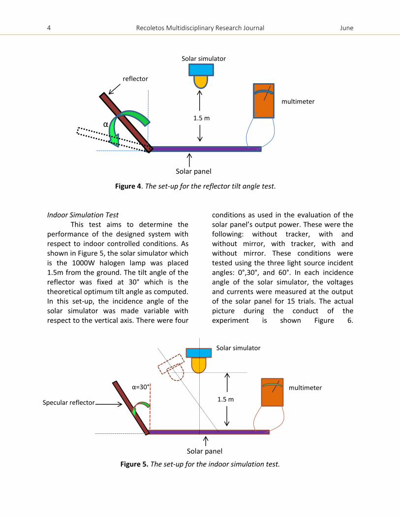
This experiment aims to determine the optimum tilt angle (α) of the specular reflector. The optimum tilt angle is the value of α with the highest output power as measured. As shown in Figure 4, a solar simulator was placed 1.5 meters above the solar panel. The specular reflector was adjusted from 0° to 60° at an interval of 5° from the vertical. A digital multimeter was used to measure the currents and voltages for each tilt angle at the output of the solar panel. The optimum tilt angle of the specular reflector is determined by considering the output power.
4 Recoletos Multidisciplinary Research Journal June
Figure 4. The set-up for the reflector tilt angle test.
Indoor Simulation Test
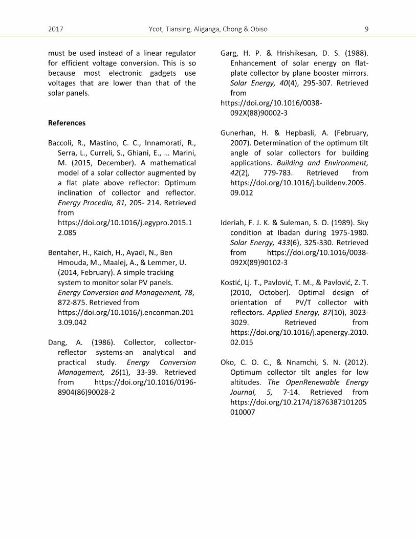
This test aims to determine the performance of the designed system with respect to indoor controlled conditions. As shown in Figure 5, the solar simulator which is the 1000W halogen lamp was placed 1.5m from the ground. The tilt angle of the reflector was fixed at 30° which is the theoretical optimum tilt angle as computed. In this set-up, the incidence angle of the solar simulator was made variable with respect to the vertical axis. There were four
conditions as used in the evaluation of the solar panel’s output power. These were the following: without tracker, with and without mirror, with tracker, with and without mirror. These conditions were tested using the three light source incident angles: 0°,30°, and 60°. In each incidence angle of the solar simulator, the voltages and currents were measured at the output of the solar panel for 15 trials. The actual picture during the conduct of the experiment is shown Figure 6.
Figure 5. The set-up for the indoor simulation test.
reflector
Solar simulator
Solar panel
α
multimeter
1.5 m
α=30°
Solar panel
Specular reflector
Solar simulator
multimeter
1.5 m

2017 Ycot, Tiansing, Aliganga, Chong & Obiso 5
Figure 6. Picture during the conduct of the indoor simulation tests in the ECE laboratory room of CIT-University (Photo taken by Aliganga,M.) Outdoor Solar Test
This test aims to evaluate the performance of the system under actual outdoor conditions. The designed system was subjected to actual sunlight. This test was conducted in the grounds of CIT-University for five (5) days in order to expose the system to different weather conditions. To reduce the number of set-ups, the largest power output in the indoor simulation test was used in this experiment and that was the set-up with tracker and with reflector. The test was conducted from 6:00 AM to 6:00 PM. In this test, the tilt angle of the reflector was fixed at 30° with respect to the vertical as shown in Figure 7. The output voltages and currents were then recorded for every two (2) hour interval. The controlled variables were the set-up without tracker and without reflector. The actual picture during the conduct of the experiments is shown in Figure 8.
Figure 7. The set-up for the outdoor solar test
Figure 8. Picture during the conduct of the outdoor solar tests in the CIT-University grounds (Photo taken by Aliganga, Michaela). 3.0 Results and Discussions
The following were the results of the different experiments as performed to evaluate the designed system. Reflector Tilt Angle Test
The results of this test are shown in Table 1. As observed in the results, the optimum tilt angle of the reflector is at 35° with respect to the vertical. Other tilt angles

6 Recoletos Multidisciplinary Research Journal June
approaching perpendicular or parallel to the ground had the least effect on the power output. The tangential specular reflector does not have a remarkable effect on the output power since light outside the vicinity of the panel does not hit the reflector at all. For tilt angles greater than 35°, more light is incident to the reflector, but lesser light is reflected towards the panel. The graph of the output power for each reflector tilt angle was also shown in Figure 9. Table 1. Solar panel output power with respect to different reflector tilt angles
Figure 9. Graph of reflector tilt angle versus output power Indoor Simulation Test
The output power of the solar panel as shown in Table 2 was determined using the voltage and current readings at the output of the solar panel. The three tilt angles as chosen were based upon the three equal distributions of the solar panel’s first quadrant position. This is assuming a symmetrical response in the second quadrant. It was found out that the set-up with of solar panel with solar tracker and reflector yielded the highest value of output power. It was also observed that as the solar simulator is getting away from the normal, the output power decreases when the panel slope remains at 0°. Also, the output power is maintained at maximum when the panel’s slope is adjusted accordingly for it to face directly to the solar simulator. Table 2. Average output power of solar panel for different reflector tilt angle with and without solar tracker
Tilt Angle, α Output Power (W)
0° 10.78 5° 10.80
10° 10.86 15° 10.89 20° 10.90 25° 10.91 30° 11.21 35° 11.51 40° 10.98 45 10.89 50° 10.75 55° 10.75 60° 10.75 Average Output Power (W)
Without Solar
Tracker With Solar Tracker
Tilt Angle
No reflector
With reflector
No reflector
With reflector
0° 10.766 11.951 10.762 11.981
30° 4.080 5.063 10.500 11.776
60° 3.492 4.097 9.830 11.513 10
10.5
11
11.5
12
0 5 10 15 20 25 30 35 40 45 50 55 60
Ou
tpu
t P
ow
er, W
Reflector Tilt Angle, degrees

2017 Ycot, Tiansing, Aliganga, Chong & Obiso 7
Outdoor Solar Test The solar panel was tested in outdoor condition to expose it under different weather conditions. It was observed in Table 3 that the tracker and reflector combination yielded the higher output powers than the set up with no reflector and no tracker. Specifically, the highest output power for tracker and reflector combination was obtained at 12NN. It can also be observed that during early and late hours of the day, the significant drop of output power can be compensated by the combination of a tracker and specular reflector. The graphs of the two set-ups were shown in Figure 10. It was very evidential that the incorporation of the reflector and the tracker to the conventional solar panel offers a significant increase in the output power. Table 3. Output power for the different conditions of tracker and reflector at different times of the day
Time
No Reflector & No Tracker
(Output Power)
With Reflector & With Tracker (Output Power)
6AM 14.17 W 21.28 W 8AM 18.30 W 27.90 W
10AM 21.06W 28.35 W 12NN 23.15W 28.67 W 2PM 19.47W 23.83 W 4PM 14.50W 24.81 W 6PM 9.97W 26.10 W
Figure 10. Graph of output power at different times of the day considering the two set-ups (no reflector-no tracker and with tracker-with reflector) Solar Panel Efficiency The set up without tracker and without mirror was the controlled variable for both the indoor and outdoor experiments. As based from the solar panel manufacturer’s website, the panel as used is 16.5% efficient at standard testing conditions. However, the equipment used in the performed solar simulation did not meet standard testing conditions. The maximum values for efficiency calculations were adjusted to match the solar panel’s rating. Using the 1000W halogen lamp, the solar panel’s maximum output power without optimizers is approximately half of the manufacturer’s rated output power. By this, it was approximated that the incident energy of the light source is 440W/m2 for efficiency matching purposes. However, the solar panel’s efficiency was measured using the formula:
ɳ=
05
101520253035
6:0
0 A
M
8:0
0 A
M
10
:00
AM
12
:00
NN
2:0
0 P
M
4:0
0 P
M
6:0
0 P
M
NoReflector& NoTracker
WithReflector& WithTracker
Ou
tpu
t P
ow
er, W
Time of the Day

8 Recoletos Multidisciplinary Research Journal June
where: ɳ= efficiency
P= output power E= energy A= surface area of the panel
It was observed in Table 4 that for the set up with error only, there was a slight increase in average efficiency. The highest increase in average efficiency was observed using the set up with tracker and with reflector. Thus, the highest efficiency is at 0° when the light source’s angle of incidence is 0° and the solar panel has tracker and a reflector. The efficiency boost was computed by taking the percentage difference of the three set ups with respect to the controlled variable. Only the values in Table 4 were used since these represents the solar panel’s output response in one day. It was observed in Table 5 that the set up with tracker and reflector obtained the highest efficiency boost. Table 4. Efficiency of solar panels at different conditions of reflector and tracker
Table 5. Efficiency boost of non-conventional set-ups
4.0 Conclusion A solar tracker with specular reflector had been developed using localized materials. Experimental data shows that when the solar panel is perpendicular to the light source, the system yields the maximum output power. The need for a tracking and a specular system is very significant when the light source moves away from the normal. This results to a significant drop in the efficiency of the solar panel. Among the possible configurations of the system, the addition of the tracker alone had greater enhancement than the specular reflector only. The tracker boosts the efficiency by 69.55% while the specular reflector boosts it by only 15.12%. However, combining the tracker and the specular reflector yields the best result with an average efficiency of 92.33%. While the designed solar tracker system already has the dual axis tracking feature, it is recommended to add a third axis tracking mechanism to adjust the entire system’s tilt with respect to the elevation of the sun. It has been observed that the sun’s elevation changes by some degrees throughout the year. Also, the LDR-compass alignment has been observed to have problems in tracking especially when the battery’s voltage becomes low. To address this issue, a separate power source must be incorporated. Further, a DC to DC converter
Average Efficiency, %
Without Tracker With Tracker
Angle of Incidence
No reflector
With reflector
No reflector
With reflector
0° 16.31 18.11 16.3 18.15
30° 6.18 7.67 15.91 17.84
60° 5.29 6.21 14.89 17.44
Average 9.26 10.66 15.70 17.81
Without Tracker With Tracker
No reflector
With reflector
No reflector
With reflector
Control 15.12% 62.55% 92.33%
2017 Ycot, Tiansing, Aliganga, Chong & Obiso 9
must be used instead of a linear regulator for efficient voltage conversion. This is so because most electronic gadgets use voltages that are lower than that of the solar panels. References Baccoli, R., Mastino, C. C., Innamorati, R.,
Serra, L., Curreli, S., Ghiani, E., … Marini, M. (2015, December). A mathematical model of a solar collector augmented by a flat plate above reflector: Optimum inclination of collector and reflector. Energy Procedia, 81, 205- 214. Retrieved from https://doi.org/10.1016/j.egypro.2015.12.085
Bentaher, H., Kaich, H., Ayadi, N., Ben
Hmouda, M., Maalej, A., & Lemmer, U. (2014, February). A simple tracking system to monitor solar PV panels. Energy Conversion and Management, 78, 872-875. Retrieved from https://doi.org/10.1016/j.enconman.2013.09.042
Dang, A. (1986). Collector, collector-
reflector systems-an analytical and practical study. Energy Conversion Management, 26(1), 33-39. Retrieved from https://doi.org/10.1016/0196-8904(86)90028-2
Garg, H. P. & Hrishikesan, D. S. (1988). Enhancement of solar energy on flat-plate collector by plane booster mirrors. Solar Energy, 40(4), 295-307. Retrieved from
https://doi.org/10.1016/0038-092X(88)90002-3
Gunerhan, H. & Hepbasli, A. (February,
2007). Determination of the optimum tilt angle of solar collectors for building applications. Building and Environment, 42(2), 779-783. Retrieved from https://doi.org/10.1016/j.buildenv.2005.09.012
Ideriah, F. J. K. & Suleman, S. O. (1989). Sky
condition at Ibadan during 1975-1980. Solar Energy, 433(6), 325-330. Retrieved from https://doi.org/10.1016/0038-092X(89)90102-3
Kostid, Lj. T., Pavlovid, T. M., & Pavlovid, Z. T.
(2010, October). Optimal design of orientation of PV/T collector with reflectors. Applied Energy, 87(10), 3023-3029. Retrieved from https://doi.org/10.1016/j.apenergy.2010.02.015
Oko, C. O. C., & Nnamchi, S. N. (2012).
Optimum collector tilt angles for low altitudes. The OpenRenewable Energy Journal, 5, 7-14. Retrieved from https://doi.org/10.2174/1876387101205010007