Integration of High Power, Long Pulse Operation in Tore ...
12
1 OV/3-1 Integration of High Power, Long Pulse Operation in Tore Supra in Preparation for ITER. M. Chatelier on behalf of Equipe Tore Supra Association Euratom-CEA, CEA-DSM-DRFC, F-13108 St Paul-lez-Durance, France e-mail contact of main author: [email protected] Abstract. Tore Supra routinely addresses the physics and technology of very long duration plasma discharges, thus bringing key information on critical issues of long pulse/steady-state operation of ITER. During the last two years, its scientific programme has entered a new phase toward higher power long pulse. Considerable progress has been accomplished towards reliable and safe operation at multi-MW power level in an actively cooled PFCs environment. Discharges lasting several resistive times, with combined LHCD and ICRH at high power level, in plasmas close to the Greenwald limit and T i close to T e have been obtained. Improved confinement has been maintained together with q(0) ~1.5 for duration up to 20 s. An advanced scheme for the physics and operational integration of plasma scenarios has been developed, and discharges at 7 MW total injected power level have been controlled in an MHD stable region for 60 s. The unique capability of the reflectometry system of Tore Supra has allowed detailed studies of particle/energy transport, and a weak dependence of confinement with β is corrobated by fluctuation measurements. A new mechanism is proposed to explain the D retention observed in long pulses. Analysis of large parallel flows in the SOL lends credence to the hypothesis that the SOL is fed by long range transport events that are created near the outboard midplane. Finally, new technological developments for in situ follow-up of PFCs ageing are reported. 1. Introduction Achieving long-duration high performance discharges in a magnetic fusion device is one of the most important challenges "en route" to a fusion reactor [1]. The mission of Tore Supra as the largest super-conducting tokamak presently in operation (minor radius a ≤ 0.78 m, major radius R ≤ 2.40 m, plasma current I p ≤ 2 MA), is to produce and study such discharges. Amongst many results, the first ten years of Tore Supra exploitation not only demonstrated the reliable operation of superconducting magnets in a large tokamak environment, but also allowed thoroughly assessing the requirements for long pulse achievement. This led to a strong development programme culminating in the completion in 2002 of the CIEL project [2]. With this major upgrade of its internal components increasing the heat exhaust capability up to 25 MW steady state (15 MW convected, 10 MW radiated), Tore Supra is now routinely addressing the physics and technology of very long duration plasma discharges, thus bringing key information on critical issues of long pulse/ steady-state operation for ITER. Steady-state discharges lasting more than 6 min and a total injected energy of 1 GJ have been obtained [3,4], although at moderate heating power (<3 MW), plasma current (I p < 0.6 MA) and density (central electron density n e0 < 3×10 19 m −3 ). This is due to the present limitations of the non inductive current drive systems of Tore Supra, initially designed for 30 seconds operation. Tore Supra will have the potential to go significantly beyond this performance (at least an order of magnitude in the injected energy) once the heating system upgrade, known as CIMES project [5], is completed. At that point, steady-state discharges at much higher heating power (12-15 MW) and densities close to the Greenwald limit will be possible. In this perspective, during the last two years, the scientific programme of Tore Supra has entered a new phase. Beside extensive investigation of the physics of fully non inductive discharges, scenarios and experimental techniques to be applied in the subsequent phase of Tore Supra are actively prepared: this involves in particular the development of feedback control techniques, operation of the machine at its present performance limits in power and density, the search of scenarios with improved confinement and MHD stability in conditions expected with CIMES. Such a programme not only requires developing sound technologies, but also a strong modelling activity in order to integrate the various constraints through innovative control schemes, pioneering the integration work that will be required on ITER. In the last two years, substantial progress along these research lines has been accomplished. Section 2 reports the real time techniques and experimental protocols developed to safely operate Tore Supra at multi-MW level. Results of long pulse experiments at high power level
Transcript of Integration of High Power, Long Pulse Operation in Tore ...
1 OV/3-1
Integration of High Power, Long Pulse Operation in Tore Supra in Preparation for ITER.
M. Chatelier on behalf of Equipe Tore Supra Association Euratom-CEA, CEA-DSM-DRFC, F-13108 St Paul-lez-Durance, France e-mail contact of main author: [email protected] Abstract. Tore Supra routinely addresses the physics and technology of very long duration plasma discharges, thus bringing key information on critical issues of long pulse/steady-state operation of ITER. During the last two years, its scientific programme has entered a new phase toward higher power long pulse. Considerable progress has been accomplished towards reliable and safe operation at multi-MW power level in an actively cooled PFCs environment. Discharges lasting several resistive times, with combined LHCD and ICRH at high power level, in plasmas close to the Greenwald limit and Ti close to Te have been obtained. Improved confinement has been maintained together with q(0) ~1.5 for duration up to 20 s. An advanced scheme for the physics and operational integration of plasma scenarios has been developed, and discharges at 7 MW total injected power level have been controlled in an MHD stable region for 60 s. The unique capability of the reflectometry system of Tore Supra has allowed detailed studies of particle/energy transport, and a weak dependence of confinement with β is corrobated by fluctuation measurements. A new mechanism is proposed to explain the D retention observed in long pulses. Analysis of large parallel flows in the SOL lends credence to the hypothesis that the SOL is fed by long range transport events that are created near the outboard midplane. Finally, new technological developments for in situ follow-up of PFCs ageing are reported. 1. Introduction Achieving long-duration high performance discharges in a magnetic fusion device is one of the most important challenges "en route" to a fusion reactor [1]. The mission of Tore Supra as the largest super-conducting tokamak presently in operation (minor radius a ≤ 0.78 m, major radius R ≤ 2.40 m, plasma current Ip ≤ 2 MA), is to produce and study such discharges. Amongst many results, the first ten years of Tore Supra exploitation not only demonstrated the reliable operation of superconducting magnets in a large tokamak environment, but also allowed thoroughly assessing the requirements for long pulse achievement. This led to a strong development programme culminating in the completion in 2002 of the CIEL project [2]. With this major upgrade of its internal components increasing the heat exhaust capability up to 25 MW steady state (15 MW convected, 10 MW radiated), Tore Supra is now routinely addressing the physics and technology of very long duration plasma discharges, thus bringing key information on critical issues of long pulse/ steady-state operation for ITER. Steady-state discharges lasting more than 6 min and a total injected energy of 1 GJ have been obtained [3,4], although at moderate heating power (<3 MW), plasma current (Ip < 0.6 MA) and density (central electron density ne0 < 3×10¹⁹ m−3). This is due to the present limitations of the non inductive current drive systems of Tore Supra, initially designed for 30 seconds operation. Tore Supra will have the potential to go significantly beyond this performance (at least an order of magnitude in the injected energy) once the heating system upgrade, known as CIMES project [5], is completed. At that point, steady-state discharges at much higher heating power (12-15 MW) and densities close to the Greenwald limit will be possible. In this perspective, during the last two years, the scientific programme of Tore Supra has entered a new phase. Beside extensive investigation of the physics of fully non inductive discharges, scenarios and experimental techniques to be applied in the subsequent phase of Tore Supra are actively prepared: this involves in particular the development of feedback control techniques, operation of the machine at its present performance limits in power and density, the search of scenarios with improved confinement and MHD stability in conditions expected with CIMES. Such a programme not only requires developing sound technologies, but also a strong modelling activity in order to integrate the various constraints through innovative control schemes, pioneering the integration work that will be required on ITER. In the last two years, substantial progress along these research lines has been accomplished. Section 2 reports the real time techniques and experimental protocols developed to safely operate Tore Supra at multi-MW level. Results of long pulse experiments at high power level
2 OV/3-1
are presented in section 3. Section 4 deals with advanced control schemes for integrating operational constraints and plasma performance. Advances in local transport analysis, substantiated by turbulence measurement, are covered in section 5. New insights in plasma wall interaction and SOL physics are discussed in section 6. Finally, technological developments for in situ monitoring and ageing follow-up of plasma facing components (PFCs) are described in section 7. 2. Safely operating Tore Supra at multi-MW level Injecting high power in Tore Supra, where all PFCs are actively cooled, raises the question of safe and reliable operation while optimising plasma performance. It is worth noting that injecting 10 MW of heating power in Tore Supra is representative of ITER operation in terms of average power density and heat exhaust capability. Table I gives the heating power required in JET and ITER to reach the same power density Pvol (heating power divided by plasma volume), power flux through the separatrix Psurf (heating power divided by plasma separatrix surface) and Plin (heating power divided by major radius of plasma) as when injecting 10 MW of heating power in Tore Supra.
TABLE I
Constant power density Pvol
(0,43 MWm-3)
Constant power flux through separatrix Psurf
(0,16 MWm-2)
Constant Plin (P/R)
(4,4 MWm-1)
Nominal heating power (MW)
Tore Supra 10 MW 10 MW 10 MW 15 MW 1000s1
JET 70 MW 40 MW 15 MW 30 MW 10s ITER 360 MW 130 MW 30 MW 150 MW > 400s2
On Tore Supra, conductive losses through the separatrix in the range 3-5 MWm-2 are routinely handled by the Toroidal Pumped Limiter (TPL), without any failure since its installation, and for routine operation with up to 10MW injected power level. However, operation at high power level has shown that the crucial plasma facing components issue in an actively cooled environment is to handle localized heat loads. In a machine relying on inertial plasma facing components for heat exhaust, an overheated spot has relatively limited consequences: locally the surface temperature raises up to the point where evaporation or radiation enhanced sublimation takes place leading to plasma quench, occurring when impurity radiation exceeds the input power or when MHD stability is lost. Such self-protection of PFCs does not exist for actively cooled PFCs: temperature raises up to the point where the brazing between the armour material and the heat sink melts, or worse where the heat sink ruptures. The constraints of safe operation with actively cooled PFCs will even be more stringent on ITER where, because of the nuclear environment, water leaks would lead to hard consequences. In order to safely operate at high heating power injection level, Tore Supra is equipped with a comprehensive infrared (IR) safety system [6], designed to oversee the entire surface of the toroidal pump limiter (TPL), the three ion cyclotron resonant heating (ICRH) antennas and the two lower hybrid current drive (LHCD) launchers. It is composed of a set of seven actively cooled IR endoscopes, each equipped with two IR cameras able to survey 2 × 35° of the TPL and one RF antenna. Digital cameras are used to protect all the elements in real time against overheating. The spatial resolution is about 9 mm, allowing control of the surface temperature of the smallest PFC elements (20 mm) with an error <10%. A striking illustration of the use of the IR safety system is the maximisation of injected power while maintaining the RF launchers temperature in the safe domain. This is a particularly challenging problem because of the variety of phenomena able to cause overheating and the technological complexity of the antennas combining items with different heat exhaust
1 After CIMES completion 2 including 100 MW due to α heating
3 OV/3-1
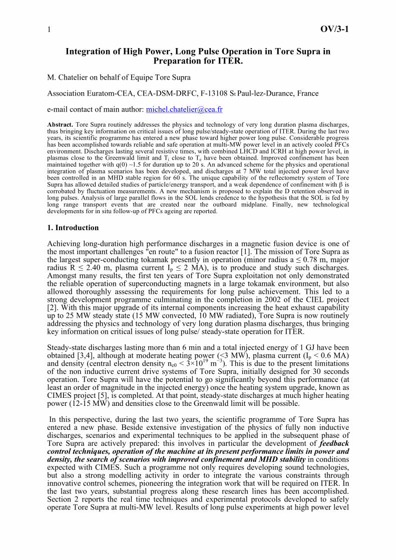
capability. In a first step, areas of potential overheat on the antennas have been identified using the IR systems. Then, the associated heat sources have been identified by varying the plasma parameters and analysing the IR and calorimetric measurements from the cooling loops of the antennas and launchers. This analysis has led to a list of critical areas of potential overheat and their related heat source. For LHCD launchers (see Fig. 1), they consist of:
• Area A: fast electrons accelerated in the near field of the LHCD coupler [7], intercepted on the inside of the guard limiter of the launcher. The maximum allowable temperature (Tmax) for safe operation is 800°C. The safety strategy to prevent overheating is to gradually decrease the power delivered by the concerned launcher down to safe operation. • Area B: fast ions large banana direct losses. Tmax = 600°C. The safety strategy is to
gradually decrease the total ICRH power. • Area C: arcing at the grill mouth. The safety strategy is to promptly decrease the
power delivered by the concerned launcher to 25% of the original value followed by a progressive reapplication of the full power.
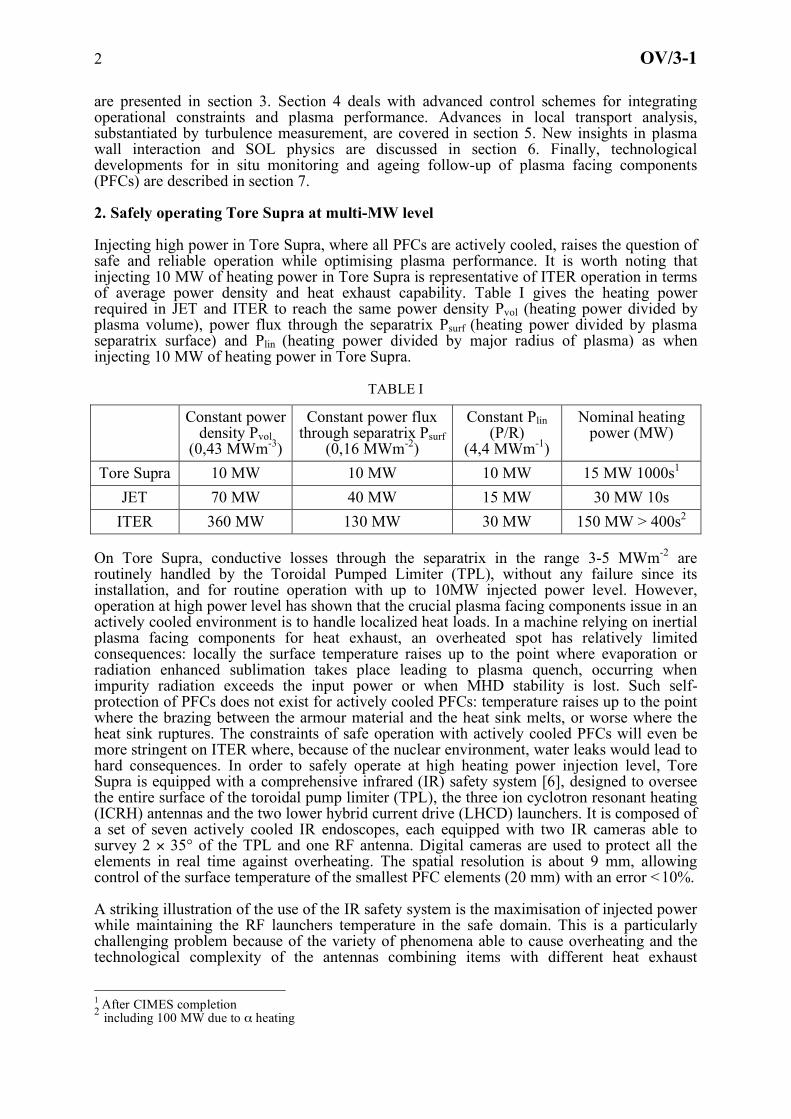
For ICRH antennas (see Fig. 2), they consist of: • Area A: fast electrons accelerated in the near field of the LHCD coupler intercepted on
the outside of the guard limiter of the ICRH antenna connected by magnetic field lines to a LHCD coupler. Tmax = 1000°C. The safety strategy is to gradually decrease the power of the connected LHCD launcher. • Area B and B’: fast ions direct losses. Tmax = 800°C (B), Tmax = 1000°C (B’). The
safety strategy is to gradually decrease the total ICRH power. • Area C: rectified sheath effects [8]. Tmax = 800°C. The safety strategy is to gradually
decrease the power delivered by the concerned antenna.
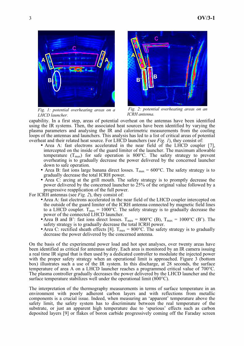
On the basis of the experimental power load and hot spot analyses, over twenty areas have been identified as critical for antennas safety. Each area is monitored by an IR camera issuing a real time IR signal that is then used by a dedicated controller to modulate the injected power with the proper safety strategy when an operational limit is approached. Figure 3 (bottom box) illustrates such a use of the IR system. In this discharge, at 28 seconds, the surface temperature of area A on a LHCD launcher reaches a programmed critical value of 700°C. The plasma controller gradually decreases the power delivered by the LHCD launcher and the surface temperature stabilizes well under the operational limit (800°C). The interpretation of the thermography measurements in terms of surface temperature in an environment with poorly adherent carbon layers and with reflections from metallic components is a crucial issue. Indeed, when measuring an ‘apparent’ temperature above the safety limit, the safety system has to discriminate between the real temperature of the substrate, or just an apparent high temperature due to ‘spurious’ effects such as carbon deposited layers [9] or flakes of boron carbide progressively coming off the Faraday screen
Fig. 2: potential overheating areas on an ICRH antenna.
Fig. 1: potential overheating areas on a LHCD launcher.
4 OV/3-1
box of ICRH antennas. In both cases, the thermal connection between the spurious zones and the heat sink is weak: as a result, the surface temperature of these spurious zones rises up to equilibration between heating by the incident flux and radiative cooling or sublimation, without any consequence for the PFCs. However, if not properly treated, the high surface ‘apparent’
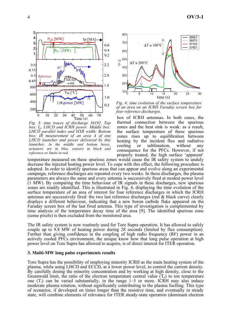
temperature measured on these spurious zones would cause the IR safety system to unduly decrease the injected heating power level. To cope with this effect, the following procedure is adopted. In order to identify spurious areas that can appear and evolve along an experimental campaign, reference discharges are repeated every two weeks. In these discharges, the plasma parameters are always the same and every antenna is successively fired at modest power level (1 MW). By comparing the time behaviour of IR signals in these discharges, new spurious zones are readily identified. This is illustrated in Fig. 4, displaying the time evolution of the surface temperature of an area of interest for four reference discharges in which the ICRH antennas are successively fired: the two last reference discharges (red & black curve) clearly displays a different behaviour, indicating that a new boron carbide flake appeared on the Faraday screen box of the last fired antenna. This type of investigation is complemented by time analysis of the temperature decay time of the area [9]. The identified spurious zone (some pixels) is then excluded from the monitored area. The IR safety system is now routinely used for Tore Supra operation. It has allowed to safely couple up to 9.8 MW of heating power during 28 seconds (limited by flux consumption). Further than giving confidence in the coupling of high radio frequency (RF) power in an actively cooled PFCs environment, the unique know how that long pulse operation at high power level on Tore Supra has allowed to acquire, is of direct interest for ITER operation. 3. Multi-MW long pulse experiments results Tore Supra has the possibility of employing minority ICRH as the main heating system of the plasma, while using LHCD and ECCD, at a lower power level, to control the current density. By carefully dosing the minority concentration and by working at high density, close to the Greenwald limit, the ratio of the electron temperature central value (Te) to ion temperature one (Ti) can be varied substantially, in the range 1–5 or more. ICRH may also induce moderate plasma rotation, without significantly contributing to the plasma fuelling. This type of scenarios, if developed on times longer than the resistive time, and eventually in steady state, will combine elements of relevance for ITER steady-state operation (dominant electron
Fig. 4: time evolution of the surface temperature of an area on an ICRH Faraday screen box for four reference discharges.
Fig. 3: time traces of discharge 36192. Top box: Ip, LHCD and ICRH power. Middle box: LHCD parallel index and HXR width; Bottom box: IR measurement of an area A of one LHCD launcher and power delivered by this launcher. In the middle and bottom boxes, actuators are in blue, sensors in black and reference or limits in red.

5 OV/3-1
heating, low momentum input, decoupling of particle fuelling, bootstrap enhancement and non-inductive current drive). An example of discharges of this type achieved on Tore Supra [10] is shown in Fig. 5. The main plasma parameters are the following: R = 2.4m, a = 0.72 m; magnetic field Bt = 3.8 T, Ip = 0.9 MA, ne0 = 5×10¹⁹ m−3. A total power in excess of 10 MW was injected, mainly by ICRH at 57 MHz in H/D minority scheme (8.4 MW), plus 1.4 MW of LHCD at 3.7 GHz and a small ohmic contribution (0.3 MW). With a minority concentration estimated at 12%, 55% of the ICRH power absorption is computed to be absorbed by the ions and 45% by the electrons, by the code PION [11], run in the framework of an interpretative transport simulation performed by the CRONOS suite of codes [12]. Globally, this discharge has still dominant electron heating, because of the LH and Ohmic parts: 55% on the electrons versus 45% on the ions. As a result, the average ion temperature is very close to the electron one, and also the radial profiles are similar, as shown in figure 6, except in the very central part, owing to the LH power deposition profile. The electron temperature is measured by the ECE radiometer and by Thomson scattering, whereas the ion temperature profile is measured by charge exchange recombination spectroscopy (CXRS). It should be noticed that for this shot the parameters fG (ratio of the line-averaged density to the Greenwald density) and Ti /Te are very close to those of a standard ITER scenario for steady state operation. The stored energy exceeds the ITER thermal L-mode scaling [13] prediction, which is typically well in agreement with the scaling of the Tore Supra L-mode discharges. In these high density discharges using high minority scheme, the energy stored in the fast particles is negligible (less than 10% from the total stored energy as estimated from kinetic measurements). Discarding the fast particle contribution leads to a thermal improvement factor of 1.3. Note that although the bootstrap fraction remains rather modest (15%), this is not a negligible value
Fig. 5: Time traces of discharge 33612. Top box: powers in MW; middle box: normalized beta and Greenwald fraction; bottom box: total energy from diamagnetic measurements (Wdia), thermal energy from kinetic measurements (Wth) compared to ITER L-mode scaling law prediction.
Te Ti
Fig. 6: Te and Ti profile during the stationary phase of discharge 33612
Fig. 7: toroidal rotation velocity for the ohmic (blue diamond) and ICRH heated (red square) phase of four high power discharges.

6 OV/3-1
for a plasma with L-mode edge. A favourable characteristic occurs in those high power/ high minority scheme discharges: plasmas exhibit a spontaneous toroidal counter rotation up to 70 kms-1 in the core region. Fig. 7 displays the radial profiles of toroidal rotation measured by CXRS for four consecutive discharges with feature similar to discharge 33612. It suggests the presence of a sheared rotation at R = 2.8 m. Stability analysis [14] indicates that both the Ion Temperature Gradient (ITG) and Trapped Electron (TE) modes are expected to be stabilized by the E×B shear produced by the sheared rotation. Stabilizing ITG and TE modes could indeed explain the observation of the confinement improvement. Discharges at similar or higher Greenwald factors have also been obtained at lower current, Ip = 0.6 MA. For the same LH power, this has the
advantage of increasing the non-inductive fraction of the current, thus allowing discharges lasting more than 60s, and giving current profile control capability. An example of a 30 s shot is shown in figure 8, with total heating power close to 10 MW, and a fraction of non-inductive current around 50%. For this discharge, the hydrogen concentration was lower than in the previous examples (within the error bar of the measurement ∼10%), which yields a more energetic superthermal ion tail, more ripple losses and the following global repartition of the absorbed power: 32% on the ions and 68% on the electrons. The global (i.e. thermal + superthermal) confinement improvement factor is comparable to that of figure 5. This shot has no sawteeth in its stationary phase, and the reconstruction of the q profile (performed by the CRONOS code in the interpretative mode) yields a safety factor profile completely above 1. This feature is reminiscent of the hybrid scenarios [15], but with the significant difference that here the q profile is controlled by the LHCD source. 4. Integrating operational controls for steady-sate scenarios In fully non-inductive discharges, it is frequently observed that, even after several minutes, a bifurcation occurs into a regime in which a strong permanent MHD activity develops. This so-called MHD regime [16] degrades fast electron confinement as well as LHCD efficiency and confinement in the plasma core. In these discharges, the current profile is globally peaked, but hollow in the narrow core region r/a ≤ 0.2: saturated tearing modes are often observed with deleterious effects only when full reconnection of double tearing modes occurs. A map of the resistive MHD properties has been drawn as a function of Bt, Ip and the parallel index of the LHCD waves (N//) [17], allowing to identify the favourable regions for fully non inductive operation. However, these favourable regions are rather narrow and a strong effort has been undertaken to develop and validate real time (RT) tools to control the current profile and prevent the plasma to enter the deleterious MHD regime. First experiments have been conducted at low plasma current (Ip = 0.6 MA), moderate plasma density (ne0 = 2.5 1019 m-3) and low loop voltage (Vloop = 60 mV). At such plasma parameters, 2.5 MW of LHCD power are sufficient to drive 90% of the plasma current. Past experiments, have documented the dependence of the current profile with the parallel index N// of the LHCD waves [18]. It was shown that the q profile broadens as the parallel index is departing from its peak value of 1.85 for which the spectrum of the LHCD wave is the most unidirectional. In the present experiments, the broadening of the deposition of the LHCD
Fig. 8: Time traces of discharge 33898. Top box: powers in MW; middle box: normalized beta and Greenwald fraction; bottom box: safety factor at the plasma axis and non-inductive current fraction.

7 OV/3-1
wave is this time controlled directly by the parallel index. The measurement of the LHCD deposition profile is made using the hard X-ray emission (HXR) diagnostic (59 detectors distributed in two cameras). This system is capable of discriminating the energy of the bremsstrahlung emission in 8 different energy channels. For the real time measurements of the LH-deposition profile, the 60-80keV energy channel is used since it is characteristic of the non-thermal HXR emission produced by the LH wave [19]. Finally, these experiments have to be conducted at constant loop voltage: if not properly taken care of, the variation of N// modifies the LHCD efficiency thus the ohmic current that participates then to the change of the overall current profile. To minimise this effect, the feedback control of the HXR width has been coupled with the control of the ohmic current routinely used in Tore Supra long pulse experiments: the plasma current is controlled by LHCD power level and flux consumption (Vloop fixed at 60mV) by the main poloidal field amplifier voltage. This “triple control” scheme has been successfully applied, as illustrated in Fig. 9: the requested HXR width is varied in three different steps lasting about 10s each (~2 times the resistive time) while the plasma current and loop
voltage remain constant. These current control experiments have been extended to higher density (ne0 = 3.5 1019 m-3, fG = 0.65) and higher power level by adding ICRH heating. In these discharges, the current profile control feedbacks have been successfully integrated with the RT IR safety system described in section 2 (see Fig. 3). The integration of various and evolving RT controls is eased by the RT architecture implemented on Tore Supra. All sensors and actuators are connected to a shared memory network, as well as dedicated control units where specific control schemes are implemented [20]. The control units receive the real time information from the sensors and calculate the requests to be sent to the actuators. Using the integrated RT controls, discharges up to 7 MW total injected power have been maintained in an MHD stable region for 60 seconds, while maintaining the RF launchers temperature in the safe domain. Such experiments are pioneering the integration work that will be required on ITER when combining several types of control for global performance, profile shaping, plasma stability and PFC protection. 5. Turbulence measurements and local transport analysis Tore Supra is equipped with a unique reflectometry system [21]. Three X-mode reflectometers (50 to 150 GHz) measure the electron density profile from the outer edge to the high field side. Their ultra-fast sweep heterodyne system ensures a high reliability of measurement. These devices also provide the radial profile of the density fluctuations using either the fixed frequency technique or the fast sweep technique. An O-mode Doppler reflectometer (50-75 GHz) measures the poloidal velocity and the perpendicular wave number spectrum of the density fluctuations. Their unique time and spatial resolution allows in depth studies of local transport and of its link with turbulence, as illustrated bellow. Inside the q=1 surface, a progressive peaking of the electron density is observed in ohmic
Fig. 9: time traces of discharge 36133. From top to bottom: LHCD power; plasma current ; LHCD parallel index; HXR width; loop voltage. Dotted lines correspond to references.

8 OV/3-1
discharges during the recovery phase of sawteeth (see Fig. 10). Such a structure has been observed so far only in Tore Supra. Using repetitive measurements (the dwell time between two profiles was reduced to 5µs) the time evolution of this peaking has been recorded. Starting from a flat density profile after a sawtooth crash, the density increases linearly on the magnetic axis during the recovery phase, while it remains flat around the q=1 surface. This peaking can represent up to 10% of the central density, its width is typically 15 cm, while the flat region
is extended beyond the q=1 surface. From the density build-up time evolution at several location inside the q=1 surface, it is possible to derive the particle transport coefficients. The inward pinch velocity (≈ 0.1 m/s) is of the same order as the Ware pinch. The diffusion coefficient (0.05 - 0.1 m2/s), is substantially lower than in the gradient zone and is consistent with a very low level of density fluctuations measured inside the q=1 surface. It is worth noting that the density build-up disappears in plasmas with dominant non-inductive current drive where the Ware pinch vanishes and/or with high auxiliary heating power where the fluctuation level increases and anomalous pinch velocity dominates, as reported in [22]. The ITER scaling laws predict for the L-mode and H-mode a strong degradation of the confinement time with the dimensionless parameter β, the ratio of plasma pressure to magnetic pressure. However, in H-mode, dedicated experiments on JET [23] and DIII-D [24] have shown a very weak dependence with β while the JT-60U [25] results are in agreement with the original ITER scaling law. This difference remains unclear: in H-mode, the ELM physics is driven by MHD and is thus β dependent. To avoid the pedestal contribution, a β scaling experiment has been achieved in L-mode in Tore Supra. By adjusting the plasma parameters and the ICRH power level, two sets of discharges have been obtained, one at βN=0.5 (Bt=3.8T) and the other at βN=0.2 (Bt=3.2T), while keeping constant other dimensionless parameter profiles. The profile matching is good in the gradient area. Inside the q=1 surface a slight mismatch is observed due to a warmer core in the higher β set. Both global confinement time and effective diffusivity show a very weak degradation: β exponent -0.2± 0.15 for global confinement, -0.2± 0.4 for effective diffusivity, to compare to -1.4 for the ITER L-mode scaling law. This result is confirmed by density fluctuation measurements. Thanks to the broad operating band, the X-mode reflectometers accessibility allows an
overlap of fluctuation profiles in the area -0.5<r/a<0.5 for the two sets of discharges. Fig. 11 shows the fluctuation level profiles for two discharges at higher and lower β. The increase of fluctuation level inside the q=1 surface could be due to the slight mismatch of dimensionless parameters already reported. However, the fluctuation level does not change with β outside the q=1 surface, in the gradient area which is the major contributor to the confinement properties. An explanation of the contradiction between scaling experiments and scaling law, for both L and H mode, could be a bias in the extraction of dimensionless scaling laws from databases [26].
6. Plasma wall interaction issues during long discharge operation Long pulse operation on Tore Supra has allowed gaining insight on fuel retention, a crucial issue for ITER occurring on long time scales. After a first phase where the rate in the wall
Fig. 11: density fluctuation profiles for two discharges of the β scaling experiment (blue from higher β set, red from lower β set).
Fig. 10: time evolution of electron density build-up during a sawteeth recovery phase.
R (m) Elec
tron
dens
ity (1
019m
-3)
q=1 q=1
9 OV/3-1
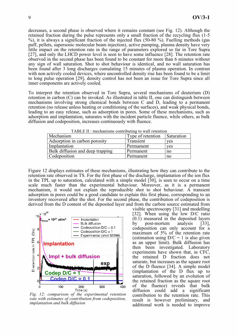
decreases, a second phase is observed where it remains constant (see Fig. 12). Although the retained fraction during the pulse represents only a small fraction of the recycling flux (1-5 %), it is always a significant fraction of the injected flux (50-80 %). Fuelling methods (gas puff, pellets, supersonic molecular beam injection), active pumping, plasma density have very little impact on the retention rate in the range of parameters explored so far in Tore Supra [27], and only the LHCD power level is seen to have some influence [28]. The retention rate observed in the second phase has been found to be constant for more than 6 minutes without any sign of wall saturation. Shot to shot behaviour is identical, and no wall saturation has been found after 3 long discharges cumulating 15 minutes of plasma operation. In contrast with non actively cooled devices, where uncontrolled density rise has been found to be a limit to long pulse operation [29], density control has not been an issue for Tore Supra since all inner components are actively cooled. To interpret the retention observed in Tore Supra, several mechanisms of deuterium (D) retention in carbon (C) can be invoked. As illustrated in table II, one can distinguish between mechanisms involving strong chemical bonds between C and D, leading to a permanent retention (no release unless heating or conditioning of the surfaces), and weak physical bonds, leading to an easy release, such as adsorption in pores. Some of these mechanisms, such as adsorption and implantation, saturates with the incident particle fluence, while others, as bulk diffusion and codeposition, increases continuously with fluence.
TABLE II : mechanisms contributing to wall retention Mechanism Type of retention Saturation Adsorption in carbon porosity Transient yes Implantation Permament yes Bulk diffusion and deep trapping Permanent no Codeposition Permanent no
Figure 12 displays estimates of these mechanisms, illustrating how they can contribute to the retention rate observed in TS. For the first phase of the discharge, implantation of the ion flux in the TPL up to saturation, calculated with a simple model [30], is seen to occur on a time scale much faster than the experimental behaviour. Moreover, as it is a permanent mechanism, it would not explain the reproducible shot to shot behaviour. A transient adsorption in pores could be a good candidate to explain this first phase, corresponding to an inventory recovered after the shot. For the second phase, the contribution of codeposition is derived from the D content of the deposited layer and from the carbon source estimated from
visible spectroscopy [31] and modelling [32]. When using the low D/C ratio (0.1) measured in the deposited layers by post-mortem analysis [33], codeposition can only account for a maximum of 5% of the retention rate (estimation using D/C = 1 is also given as an upper limit). Bulk diffusion has then been investigated. Laboratory experiments have shown that, in CFC, the retained D fraction does not saturate, but increases as the square root of the D fluence [34]. A simple model (implantation of the D flux up to saturation, followed by an evolution of the retained fraction as the square root of the fluence) reveals that bulk diffusion could add a significant contribution to the retention rate. This result is however preliminary, and additional work is needed to improve
CDmax= 1021 at/m2
exp
Implantation
Codep D/C = 1Codep D/C = 0.1
Impl + bulk diffusion
Fig. 12: comparison of the experimental retention rate with estimates of contribution from codeposition, implantation and bulk diffusion
10 OV/3-1
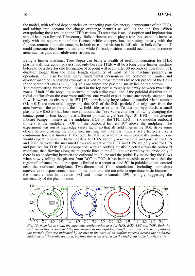
the model, with refined dependencies on impacting particles energy, temperature of the PFCs, and taking into account the charge exchange neutrals as well as the ion flux. When extrapolating these results to the ITER tritium (T) retention issue, adsorption and implantation should lead to a limited T inventory. Bulk diffusion could play a role, but seems to increase only with the square root of the fluence, while codeposition, increasing linearly with the fluence, remains the main concern. In both cases, detritiation is difficult: for bulk diffusion, T could penetrate deep into the material while for codeposition it could accumulate in remote areas such as gaps and subdivertor structures. Being a limiter machine, Tore Supra can bring a wealth of useful information for ITER plasma wall interaction physics, not only because ITER will be a long pulse limiter machine before to be a divertor one (formation of X point will occur after 30 seconds of operation [35], duration longer than the pulse length capability of most of the machine presently in operation), but also because many fundamental phenomena are common to limiter and divertor machine. A striking example is given by measurements by Mach probes of the flows in the scrape off layer (SOL) [36]. In Tore Supra, the plasma usually lies on the bottom TPL. The reciprocating Mach probe, located in the top port is roughly half way between two strike zones. If half of the recycling occurred at each strike zone, and if the poloidal distribution of radial outflux from the core were uniform, one would expect to measure nearly stagnant ion flow. However, as observed in JET [37], surprisingly large values of parallel Mach number (M// ≈ 0.5) are measured, suggesting that 90% of the SOL particle flux originates from the area between the probe and the low field side strike zone. To test this hypothesis, a small plasma (a = 0.65 m) has been moved around the Tore Supra chamber, allowing changing the contact point to four locations at different poloidal angle (see Fig. 13): HFS on six discrete inboard bumper limiters at the midplane; BOT on the TPL; LFS on six modular outboard limiters at the midplane; TOP on the outboard limiters 30° above the midplane. The experiment was run at high edge safety factor so that all field lines in the SOL strike some object before crossing the midplane, insuring that modular limiters act effectively like a continuous toroidal limiter. If the core to SOL outward flux were poloidally uniform, one would expect to measure flows negative for HFS, roughly zero for BOT and positive for LFS and TOP. However the measured flows are negative for BOT and HFS, roughly zero for LFS and positive for TOP. This is compatible with an outflux mostly injected across the outboard midplane, then flowing along the magnetic lines in the SOL and observed by the probe only if there is no shadowing between the outboard midplane and the probe. By measuring the flows when slowly rolling the plasma from BOT to TOP, it has been possible to estimate that the region of enhanced radial transport is limited to a sector around 30° in poloidal extent, centred near the outboard midplane. Two-dimensional fluid simulations including anomalous convective transport concentrated on the outboard side are able to reproduce basic features of the measurements in divertor [38] and limiter tokamaks [39], strongly suggesting the universality of the phenomenon.
Fig. 13: from left to right, the magnetic configuration uses for HFS, BOT, LFS and TOP. Both the last closed flux surface and the flux surface at one e-folding length are drawn. The main paths of the particle flow are indicated by arrows in the case of an outflux injected across the outboard midplane. At the probe location, positive flow is directed from the high field to the low field side.

11 OV/3-1
7. Technological developments for long discharge operation follow-up One very important issue, when operating a long discharge machine is to be able to follow up the inner components and evaluate their degradation in situ. A first step is to be able to perform a thorough visual inspection of the inner components without breaking the vacuum of the machine chamber. For this purpose, an articulated inspection arm (AIA) is being developed to demonstrate the feasibility of an in-vessel remote handling inspection limited payload (10 kg) carrier. The AIA robot is an 8-meter long, multi link carrier composed of 5 identical modules of 160 mm diameter with two actuated joints. Each module includes pitch (±45°) and yaw (±90°) joints linked with a parallelogram structure that keeps yaw joints axis always vertical. It weights about 120 kg. A prototype module has been mounted in a vacuum test facility (Fig. 14). After baking at 200°C during one week, various tests have been performed validating its operation under ITER representative temperature (120 °C) and vacuum conditions. Endurance tests have also been carried out at room conditions to qualify
the module performances under loading. The five modules are now under procurement and the AIA should be installed on Tore Supra in 2007 and equipped with a high definition CCD camera for PFCs visual inspection. Several other potential uses of the AIA are under studies: leak testing, laser ablation for surface characterization and codeposited layer removal…
As reported in section 2, IR systems allow to follow-up PFCs evolution during an experimental campaign. However, much more direct and precise information on ageing of PFCs can be gathered using non-destructive techniques developed for PFCs acceptance test after manufacturing, as the lock-in thermography. The lock-in thermography technique is based on the study of thermal wave propagation into the inspected sample produced by an external sinusoidal thermal stimulation. The thermal response of the component is recorded during the stimulation with an infrared device. Dedicated software and a synchronisation device perform the Fourier analysis at each pixel of the IR image. The calculated phase-shift depends on the thermal diffusivity along the heat path so that a modification of heat transfer efficiency can be detected. Lock-in thermography performed in-situ during a shut-down of Tore Supra with a dedicated experimental device able to move on the LPT surface gave first
promising results in term of health monitoring of PFCs. Fig. 15 displays the cartography of phase shift obtained on a LPT sector: 7 tiles with reduced heat transfer capacity are visible. These small defects do not impact yet the LPT capability. This follow-up will be conducted between successive experimental campaigns and will allow a precise monitoring of the LPT ageing.
8. Conclusion In the last two years, the scientific programme of Tore Supra has entered a new phase towards higher power long pulse experiments. High RF heating power, up to 10 MW level, are now routinely coupled to the plasma for duration of several tens of seconds. A unique know-how has been accumulated on safe and reliable operation at high heating power level in an environment where all plasma facing components are actively cooled. Besides development of relevant technologies and of dedicated diagnostics, this has required a detailed understanding of all involved phenomena and the integration of the various technological and
Fig. 14:AIA prototype module in vacuum test facility
Fig. 15: Phase shift cartography of one TPL sector

12 OV/3-1
physical constraints through real time feedback controls, with consideration not only for machine safety but also for plasma performance optimisation. Meanwhile, much has been learned on more fundamental issues ranging from particle and energy transport to the physics of the SOL and plasma wall interaction. Past achievements of Tore Supra have already brought a wealth of information for ITER (trouble-free use of superconducting coil in a tokamak environment for 18 years, high grade industrial quality control and comprehensive testing for actively cooled PFCs [40], conceptual and detailed design of steady state RF systems [41],…). Present achievements pioneer the integration work that will be required on ITER when combining all the constraints for steady state operation. The presently on-going upgrade of the heating systems will allow increasing Tore Supra operating domain and further addressing ITER key steady state issues. References [1] Saoutic B., Plasma Phys. Control. Fusion 44, 1-12 (2002) [2] Cordier J.J., Fusion Eng. and Des. 66-68, 59-67 (2003) [3] Van Houtte D. et al., Nucl. Fusion 44, L11-L14 (2004) [4] Jacquinot J. , Nucl. Fusion 45, S118-S131 (2005) [5] Beaumont B. et al., Fusion Eng. Des. 56–57, 667-671 (2001) [6] Guilhem D. et al., Proc. 30th EPS Conf. on Control. Fusion and Plasma Phys. (St Petersbourg, 2003) P-
1.67 [7] Goniche M. et al., Nucl. Fusion 28, 919-937 (1998) [8] Colas L. et al., Nucl. Fusion 45, 767-782 (2005) [9] Mitteau R. et al., Nucl. Fusion 46, S49-S55 (2006) [10] Giruzzi G. et al., Plasma Phys. Control. Fusion 47, B93-B105 (2004) [11] Eriksson L.G. et al., Nucl. Fusion 33, 1037-1048 (1993) [12] Basiuk V. et al., Nucl. Fusion 43, 822-830 (2003) [13] ITER Physics Basis, Nucl. Fusion 39, 2201-2209 (1999) [14] Fenzi-Bonizek C. et al., Proc. 31th EPS Conf. on Controlled Fusion and Plasma Physics (London, 2004)
P4.099 [15] Gormezano C. et al., Plasma Phys. Control. Fusion 46, B435-B448 (2004) and references therein [16] Maget P. et al., Nucl. Fusion 44, 443-451 (2004) [17] Maget P. et al., Nucl. Fusion 45, 69-80 (2005) [18] Wijnands T. et al., Plasma Phys. Control. Fusion 43,1291-1302 (2001) [19] Peysson Y. et al., Rev. Sci. Instrum. 70, 3987-4007 (1999) [20] Moreau Ph. et al., to be published in Fusion Eng. Des. [21] Sabot R. et al., Int. J. Infrared Millim. Waves. 25, 229-246 (2004 [22] Hoang T. et al., Phys. Rev. Lett. 90, 155502-1/4 (2003) [23] McDonald D.C. et al., Plasma Phys. Control. Fusion 46, A215-A225 (2004) [24] Petty C.C. et al., Phys. Plasmas 11, 2514-2522 (2004) [25] Urano H. et al., Nucl. Fus. 46, 781-787 (2006) [26] Cordey J.G. et al., Nucl. Fusion 45, 1078-1084 (2005) [27] Tsitrone E. et al., Proc. 20th IAEA Fusion Energy Conference (Vilamoura, 2004) EX/10.2 [28] Bucalossi J. et al., Proc. 32th EPS Conf. on Control. Fusion and Plasma Phys. (Taragona, 2005) O-4.05 [29] Tsitrone E., to be published in Journal Nucl. Mat. [30] Tsitrone E. et al., Journal Nucl. Mat. 337-339, 664-668 (2005) [31] Dufour E. et al., Proc. 32th EPS Conf. on Control. Fusion and Plasma Phys. (Taragona, 2005) P5.002 [32] Hogan J. et al., EX/P4.8, this conference [33] Brosset C. et al., to be published in Journal Nucl. Mat. [34] Roth J., to be published in Journal Nucl. Mat. [35] ITER Design Description Document DDD-11, 43-51 (2004) [36] Gunn J. et al., EX/P4.9, this conference [37] Erents S.K. et al., Plasma Phys. Control. Fusion 46, 1757-1780 (2004) [38] Pigarov A.Y. et al., Contrib. Plasma Phys. 44, 228-237 (204) [39] Zagorski R. et al., to be published in Journal Nucl. Mat. [40] Durocher A. et al., FT/1.5, this conference [41] Beaumont B. et al., IT/2.5, this conference