Integration of Heterogeneous Systems - GUPEA: Home component integration. ... Component-Based ......
149
Abstract: This master thesis concerns principles and technologies for software component integration. It provides an overview of Component-Based Software Development (CBSD), which is a new paradigm for information systems development. It focuses on the comparison of three different techniques: Enterprise JavaBeans, COM and CORBA. To investigate different principles and techniques, we have performed a literature study and made some qualitative interviews with people that have experience from integration tasks/questions. We have also developed a small prototype using Enterprise JavaBeans. We have found design patterns to be useful principles for the integration of software components. Our comparison of the three techniques shows that they have much in common, but that they also differ in some important aspects. Integration of Heterogeneous Systems - A Component-Based Approach - Master of Science Thesis June, 2001 Anna Eriksson Ali Reza Feizabadi Baranoush Zamani Supervisors: Maria Bergenstjerna, Department of Informatics Andreas Jirvén, Ericsson Microwave Systems AB
-
Upload
hoanghuong -
Category
Documents
-
view
229 -
download
0
Transcript of Integration of Heterogeneous Systems - GUPEA: Home component integration. ... Component-Based ......

Abstract:
This master thesis concerns principles and technologies forsoftware component integration. It provides an overview ofComponent-Based Software Development (CBSD), which is anew paradigm for information systems development. It focuseson the comparison of three different techniques: EnterpriseJavaBeans, COM and CORBA. To investigate differentprinciples and techniques, we have performed a literature studyand made some qualitative interviews with people that haveexperience from integration tasks/questions. We have alsodeveloped a small prototype using Enterprise JavaBeans. Wehave found design patterns to be useful principles for theintegration of software components. Our comparison of the threetechniques shows that they have much in common, but that theyalso differ in some important aspects.
Integration of Heterogeneous Systems
- A Component-Based Approach -
Master of Science Thesis June, 2001
Anna ErikssonAli Reza FeizabadiBaranoush Zamani
Supervisors:Maria Bergenstjerna, Department of InformaticsAndreas Jirvén, Ericsson Microwave Systems AB

We are grateful to Maria Bergenstjerna, our supervisor at the Informatics institute inGothenburg University, for her support, guidance, and encouragement.
We would also like to thank Andreas Jirvén, our supervisor at Ericsson TelecomManagement. He initiated this master thesis project and has helped us through ourinvestigation. We are grateful to his support, advice and feedback.
A special thanks goes to Johanna Kjellberg System & Integration Manager atEricsson Telecom Management for her enthusiasm to this work and all resources wegot to accomplish it.
Thanks are extended to the interview persons of this investigation.

Integration of Heterogeneous Systems – A Component-Based Approach
- 1 -
Table of Contents
1 INTRODUCTION .....................................................................................................................................................3
1.1 PURPOSE ..................................................................................................................................................................31.2 PROBLEM DEFINITION ..............................................................................................................................................41.3 BACKGROUND .........................................................................................................................................................41.4 DISPOSITION ............................................................................................................................................................5
2 METHOD...................................................................................................................................................................7
2.1 LITERATURE STUDY .................................................................................................................................................82.2 INTERVIEWS.............................................................................................................................................................92.3 PROTOTYPE..............................................................................................................................................................9
3 THEORY..................................................................................................................................................................10
4 COMPONENT-BASED SOFTWARE DEVELOPMENT...................................................................................16
4.1 TWO EXTREMES AND THE THIRD WAY....................................................................................................................174.2 THE BENEFITS OF COMPONENT-BASED DEVELOPMENT.........................................................................................184.3 INTRODUCTION TO SOME FUNDAMENTAL CONCEPTS .............................................................................................20
4.3.1 Components .................................................................................................................................................204.3.2 Interfaces.....................................................................................................................................................254.3.3 Contracts .....................................................................................................................................................264.3.4 Design Patterns and Frameworks ...............................................................................................................27
4.4 ACTIVITIES OF THE COMPONENT-BASED DEVELOPMENT APPROACH ....................................................................29
5 INTEGRATION PRINCIPLES .............................................................................................................................32
5.1 INTRODUCTION ......................................................................................................................................................325.2 DESIGN PATTERNS .................................................................................................................................................34
5.2.1 Adapter ........................................................................................................................................................355.2.2 Bridge ..........................................................................................................................................................365.2.3 Proxy ...........................................................................................................................................................375.2.4 Mediator ......................................................................................................................................................385.2.5 Facade.........................................................................................................................................................395.2.6 Other patterns..............................................................................................................................................40
6 INTEGRATION TECHNIQUES...........................................................................................................................44
6.1 DOMINATING TECHNIQUES ....................................................................................................................................446.1.1 Enterprise JavaBeans..................................................................................................................................446.1.2 Component Object Model............................................................................................................................686.1.3 CORBA (Common Object Request Broker Architecture) ............................................................................82
6.2 OTHER TECHNIQUES ............................................................................................................................................1036.2.1 Jini.............................................................................................................................................................1036.2.2 Message Broker.........................................................................................................................................1076.2.3 Intelligent Agents.......................................................................................................................................112
7 INTERVIEWS .......................................................................................................................................................115
7.1 INTERVIEW NO. 1 ................................................................................................................................................1157.1.1 Integration Difficulties and Principles ......................................................................................................1157.1.2 Component-Based Software Development ................................................................................................1157.1.3 Integration Techniques..............................................................................................................................116
7.2 INTERVIEW NO. 2 ................................................................................................................................................1167.2.1 Integration Difficulties and Principles ......................................................................................................1177.2.2 Component-Based Software Development ................................................................................................1177.2.3 Integration Techniques..............................................................................................................................117
7.3 INTERVIEW NO. 3 ................................................................................................................................................1187.3.1 Integration Difficulties and Principles ......................................................................................................118

Integration of Heterogeneous Systems – A Component-Based Approach
- 2 -
7.3.2 Component-Based Software Development ................................................................................................1187.3.3 Integration Techniques..............................................................................................................................119
7.4 INTERVIEW NO. 4 ................................................................................................................................................1197.4.1 Integration Difficulties and Principles ......................................................................................................1207.4.2 Component-Based Software Development ................................................................................................1207.4.3 Integration Techniques..............................................................................................................................120
8 PROTOTYPE ........................................................................................................................................................121
8.1 OBJECTIVES .........................................................................................................................................................1218.2 REQUIREMENTS ...................................................................................................................................................1218.3 TOOLS/INSTALLATION .........................................................................................................................................1218.4 TRAINING.............................................................................................................................................................1228.5 MODELLING.........................................................................................................................................................1228.6 PROGRAMMING....................................................................................................................................................123
9 RESULTS...............................................................................................................................................................125
9.1 RESULTS FROM LITERATURE STUDY.....................................................................................................................1259.1.1 Some points from the literature analysis ...................................................................................................1259.1.2 Comparison of the dominating techniques ................................................................................................126
9.2 RESULTS FROM INTERVIEWS ................................................................................................................................1329.2.1 Integration Difficulties and Principles ......................................................................................................1329.2.2 Component-Based Software Development ................................................................................................1329.2.3 Integration techniques...............................................................................................................................132
9.3 PROTOTYPING EXPERIENCE..................................................................................................................................1349.3.1 Development Tool Demanding ..................................................................................................................1349.3.2 Development Tool Dependence.................................................................................................................1349.3.3 Interoperability with CORBA ....................................................................................................................1359.3.4 Inherent Technique Complexity.................................................................................................................1359.3.5 Support for basic information management services ................................................................................1359.3.6 Performance ..............................................................................................................................................135
10 DISCUSSION.........................................................................................................................................................136
10.1 A CRITICAL VIEW ON OUR WORK.....................................................................................................................13610.2 CONCLUSIONS.................................................................................................................................................136
10.2.1 Question 1 .................................................................................................................................................13710.2.2 Question 2 .................................................................................................................................................13710.2.3 Question 3 .................................................................................................................................................138
11 APPENDIX.............................................................................................................................................................140
11.1 INTERVIEW QUESTIONS...................................................................................................................................14011.2 THE ZACHMAN FRAMEWORK..........................................................................................................................141
12 REFERENCES ......................................................................................................................................................142
12.1 BOOKS ............................................................................................................................................................14212.2 WEB REFERENCES ...........................................................................................................................................143

Integration of Heterogeneous Systems – A Component-Based Approach
- 3 -
1 Introduction
One of the major problems with integrating complex information systems is the heterogeneousand different subsystems. According to the Hypertext Webster online dictionary (2001),heterogeneous means “consisting of elements that are not of the same kind or nature”.
Most large-scale information systems solutions in business, science and administration todaytend to share some common characteristics. An essential one among them is, becoming stronglyheterogeneous in their technical and organizational context. We mean by that, diversity anddissimilarity in type, structure, logical, and technical dependencies of their consisting parts.(Kutsche & Sünbül, 1999)
It leads to that they require the capability of handling syntactical and semantic heterogeneity inthe process of component integration and federation of many different, but logically relatedinformation resources.
Often the communication between the system parts is handled in an “ad hoc” way. Theintegration is accomplished for the particular case at hand, without consideration of widerapplication. This leads to problems with inflexibility, inertia of change, and difficulties to have ageneral view over the system. The consequence is that when one part of a system is to bechanged or replaced, other parts of the system also will have to be changed or they will beaffected in undesirable ways. The costs in this context could sometimes be so high that it, inpractice, becomes impossible to accomplish the change.
1.1 Purpose
Our purpose was to study different principles and techniques for integration of softwarecomponents that support simple replacement of system parts, with minor modifications in theremaining system. By literature studies we have investigated the existing principles, techniquesand research in this area. We have performed some interviews with persons who have experienceof integration questions and techniques. To become more familiar and gain a betterunderstanding of integration techniques, we have developed a simple prototype in one of thestudied techniques.
Telecom Management at Ericsson Microwave Systems has a need for an integration strategy andarchitecture to make their software solutions flexible and easy to maintain and upgrade. Ourintention has also been to be able to make a suggestion of a suitable approach for this. The goalof this thesis project has been to increase the knowledge on various integration concepts,principles and technologies.

Integration of Heterogeneous Systems – A Component-Based Approach
- 4 -
1.2 Problem definition
In this thesis we have tried to answer the following general questions:
• What dominating general principles exist for software component integration and what aretheir benefits and drawbacks?
• What different integration techniques exist for this purpose and what are the main differencesbetween them?
For the specific operating support system at Ericsson Telecom Management, we had thefollowing question:
• How can their third-party products be integrated successfully, supporting simple replacementand maintenance?
1.3 Background
Today, organizations face a dynamic and heterogeneous world, in which fast responses to a turbulentenvironment, flexibility and a strategic plan for IT management are essential criteria for survival.
A survey of information systems development during the last decades shows the application of thefollowing strategies (Magoulas & Pessi,1998):
• The dominant principles during the sixties, trying to concentrate all information supply to oneintegrated system,
• Efforts during the seventies to decentralize information systems to each organizational part,• Activities during the eighties developing PC- based systems.
These efforts are essential reasons for the present situation, which can be described as a complex andproblematic world of information systems. This world is characterized of “information islands”caused by isolation, “information labyrinths” composed of conflicting architectures and “rigidstructures” caused by inflexible architectures. This has led to high costs, low information quality,poor information processing and availability and unchangeable structures. (Magoulas & Pessi, 1998)
The previous slow and almost predictable market variations have been replaced with unstable andquick changes, causing new competition situations where time is a critical factor.A complex and fast-changing environment causes external insecurity for the organization.(Christiansson & Jakobsson, 2000)
Surviving in this chaotic world and managing these problematic situations requires well-designed,flexible and maintainable information systems, which contributes to making the right decisions at theright time. This, in its turn requires well-defined integration principles to compose a collection ofinteracting system parts, which are easy to configure and replace. But, this is not an easy andproblem free process.

Integration of Heterogeneous Systems – A Component-Based Approach
- 5 -
Telecom Management is a sector in Ericsson Microwave Systems AB. Here products are developed,services and solutions for both the mobile and stationary nets as well as the data net in the area oftelecom management. The activity constitutes a strategically important section in the businessdeveloping in Ericsson and it is found to be in an expansive level.
These products are selling over the whole world market and are often an entire solution fromEricsson to telephone operators. In some cases, Ericsson has chosen as a strategy, to buy softwarefrom other companies to build bigger and more complex solutions.
Ericsson’s customers use these solutions to manage their telecommunication’s networks. Theseoperating support systems handle, among other things, alarms from the network. Some parts of thesystems need to communicate with each other. Today, the integration between two softwarecomponents happens in a unique way. It is desired that this integration happens in a reusable way. Inother words, it is desired to develop a communication-mechanism, which can be similar in allinterfaces between different components.
Integration is the key word for this work. In this work we try to research the principles, which can beused in an integration work. We hope that our work can be a source of information that can give ahigher view over integration principles, techniques and other involved questions in this area.
1.4 Disposition
This master thesis has the following structure:
In chapter 2, “Method”, we describe the research methods we have used to gather information aboutthe problem area.
In chapter 3, “Theory”, we discuss systems theory, which we have used as the theoreticalfoundation for this thesis.
In chapter 4, “Component-Based Software Development”, we give an overview of CBSD, whichis a new paradigm for systems development, and the basis for the three dominating techniques,which will be described in depth in this thesis.
In chapter 5, “Integration Principles”, we describe what integration principles could be suitable forsoftware component integration.
In chapter 6, “Integration Techniques”, we present the three dominating techniques for softwarecomponent integration and give a brief overview of some alternative techniques.
In chapter 7, “Interviews”, we give an overview of each interviewee’s opinions and experience ofsoftware component integration issues.
In chapter 8, “Prototype”, we describe the process of developing our prototype.
In chapter 9, “Results”, we present our results from the literature study, from the interviews andfrom the prototyping process.

Integration of Heterogeneous Systems – A Component-Based Approach
- 6 -
In chapter 10, “Discussion”, we present our conclusions for the three questions in the problemdefinition and give a critical view over our chosen research method.
There is also an Appendix and a References section at the end of this report.

Integration of Heterogeneous Systems – A Component-Based Approach
- 7 -
2 Method
Figure 2.1 presents an overview of our research within the area of software component integration.As a foundation for our work we have chosen to use systems theory. The systems theory provides uswith basic concepts such as systems, parts, relations, etc. These concepts can be mapped to thecomponent-based software development-paradigm, which we have used as a framework for ourthesis.
We have studied the component-based software paradigm and searched for simple principles ormechanisms suitable for integrating components. We have performed theoretical and empiricalstudies of the three dominating techniques within the area of component-based software integration.
The theoretical studies of integration techniques concern the architectures of EJB, CORBA andCOM and the empirical part of our research consists of interviews with people experienced withinthe field of component integration, and the development of a simple prototype using EnterpriseJavaBeans.
We have also briefly studied some alternative techniques for software component integration,namely JINI, message brokers and intelligent agents.
Figure 2.1 A model showing our chosen path of research

Integration of Heterogeneous Systems – A Component-Based Approach
- 8 -
2.1 Literature study
We have chosen a broad explorative attempt for the literature study.
The major purpose of explorative studies is to gather as much knowledge as possible within aspecific problem area and try to illuminate the problem area comprehensively. Since thesestudies often aim at reaching knowledge that can lay the foundation of further studies, richness ofideas and creativity are important features. (Patel & Davidson, 1991).
In an explorative study, the researcher searches for knowledge in a rather unsystematic way. Theresearcher starts out from his or her own understanding and experience, reads others work andmakes preliminary inquiries to gain knowledge within the area of interest. Here, the researcher isforemost interested in describing reality and discovering new aspects of reality instead of tryingto verify or falsify already existing hypotheses or theories about reality. (Patel & Davidson,1991)
The literature study would help to increase our knowledge of different concepts, principles andtechnologies for system integration. We started to scan a broad area, to get an overview of thearea, and to be able to make a demarcation in our work. When we had become more familiarwith general principles and concepts, we studied in depth the dominating techniques and morebriefly some other techniques. Figure 2.2 depicts the areas we have covered during our literaturestudy.
Figure 2.2 Our literature study model

Integration of Heterogeneous Systems – A Component-Based Approach
- 9 -
2.2 Interviews
We have performed four interviews. The purpose with the interviews was to get some experts’point of view regarding key concepts in the area of software integration and its relatedtechnologies and to derive advantages from their experience.
Our criteria for choosing the interview persons, was that they have been involved in integrationquestions, either in business or in the academic world. The interviews were semi-structured, andtook about one hour per person. We have chosen the semi-structured model for the interviews,because of the nature of the problem domain, which makes it difficult using structured questionswith specific boundaries. It also gave us the opportunity to initiate some deeper discussions withthe interview persons.
The interview questions can be found in the Appendix.
2.3 Prototype
A prototype is a test version of a future system that does not have to be identical with the finalproduct in all respects. It is important that it is similar to the final product in the areas underexamination. Certain functionality could consciously be left out. (Wallén, 1993)
We have developed a simple prototype to become familiar with the degree of difficulty ofsoftware integration tasks and to get a better insight into a new integration technique using aserver-side component architecture, called Enterprise JavaBeans.
An advantage of building a prototype is that it gives a possibility to concretely experience theproblems of performing an integration task.

Integration of Heterogeneous Systems – A Component-Based Approach
- 10 -
3 Theory
We have decided to use systems theory as a comprehensive theory for our work. Systems theoryis generally a concept, which basically was used in 1920 by Von Bertalanffy who was a biologist.Systems theory was originally practiced in natural sciences and more in biology but in the lastyears it has also been practiced in sociology and behavioral researches. It has been even moreusual in some other sciences such as business economics, management, political science etc.(Norrbom, 1973)
Systems theory has an approach to focus on an overall and a comprehensive view as animportant aspect. It pays attention to different valuation and target understanding, which can leadto different solutions for a problem. In this way it is very important to find a system with similarstructure and also the general positions such as control and feedback. (Norrbom, 1973)
This is not so easy as it sounds because “system” as a concept has various meanings for each ofus and therefore systems theory is a very subjective concept.
Before we talk more detailed about system theory we will describe the meaning of the abovesentence in a more philosophical way.
In real life, when we want to get information about something, the first thing we do is to get aclear definition of some concepts. In this way, we often try to describe a concept in a direct way,for example:
Main question: What is a car?Answer: (A direct definition!) A car is a vehicle, which has 4 wheels, a steering wheel,
a clobber, a coach . . . etc.
In other words, in a direct definition, there is more focus on structures. A direct definition is avery usual way to describe objects, problems or concepts, often simple things.
When we meet concepts, which are more complex, a direct definition is often not enough to get aclear understanding over the problem or concept. In these cases there is another useful way todefine the problem. That is an indirect definition.
In an indirect definition we do not try to describe the concept or problem but we try to describeother things, concepts, objects or problems, which are related to the demanded concept but arestill not the concept, which we actually will define. When we have done that, we can make theconclusion that the problem, object or concept actually is something else, something, which isnot the things we already have defined!

Integration of Heterogeneous Systems – A Component-Based Approach
- 11 -
For example:Main question: What is a Wineglass?
Help questions: Do you know a usual glass? Yes Do you know a mug? Yes Do you know a snap? Yes Do you know a Cocktail glass? Yes
Do you know a Brandy glass? YesDo you know a Champagne glass? Yes
Answer: (An indirect definition!) The one that is not one of them, that is a wineglass!
Conclusion: Aha! Then I know what a wineglass is!
An indirect definition is sometimes more powerful than a direct definition, and it is often usedfor more complex concepts but even an indirect definition is not always enough to define thoseconcepts, which are really complex.
Some concepts, such as “Architecture”, “Democracy”, “System”, etc. are very difficult todescribe because they can be “translated/understood” in different ways by different persons.
In these cases there is a third way to define concepts. This third way is nothing more than a mixof both a direct and an indirect definition.
In these complex cases, if we do not use the third way to define the concepts, there is always arisk to get an “unreal” view over the concept and therewith get an understanding that is nottruthful.
For example:A democratic society is sometimes defined as a society that fulfils a number of differentconditions (right to vote, etc.). But the fact is that it can even exist some societies, which have a

Integration of Heterogeneous Systems – A Component-Based Approach
- 12 -
lot of these conditions but yet cannot be counted as democratic societies. They are ratherauthoritarian (dictator) societies than democratic societies.
So for defining a “Democracy” it is not enough to describe it just directly or just indirectly.
The best way is to first describe it directly, and beside it, also try with an indirect definition, i.e.describe an authoritarian system and the factors, which exist in an authoritarian system.
Then, we can finally make the conclusion that a Democracy is something, which has theseconditions and at the same time has not those other factors. Thus, a mix of both a direct and anindirect definition.
System as a concept is another such complex concept. In other word, different persons cantranslate it in different ways. (Johnson, Kast & Rosenzweig, 1973)
We can describe a system in a direct and structural way and say that a system is a structure of anumber of elements/components, which work together.
But we should not forget the fact that a system can even be a subsystem (a part of anothersystem) or a super/mother system, which contains a number of other systems.
With a system structure, we mean the pattern, which is built by components and the relationshipsin a system. At least, the different forms of system’s structures can be divided into three maingroups: Hierarchical, Multilateral and Temporary (which depends on time) structures.The figure 3.1 depicts just a hierarchical structure. In this work we will not describe the otherforms of system’s structures, which was named above. We just want to point out that giving astructural (direct) definition of systems, is not always enough to describe a system well.
Figure 3.1 In this hierarchical system structure (and even in the other structural forms), different observers have different focus and view over the system!
Yes I know that it is a complex system!
Yes I know that it is a complex system!
Yes I know that it is a complex system!
Yes I know that it is a complex system!

Integration of Heterogeneous Systems – A Component-Based Approach
- 13 -
As we see here a direct definition of system is not enough to get a good understanding over thisconcept.
The most difficult problem in this way is to take an acceptable restriction over the elements,which are included in an arbitrary system so “my system” even is “your system”, in other wordwe have a common view over a system! (Norrbom, 1973)
Missing this common view creates big problems because it can lead to a misunderstanding wherewe suppose that we are talking about the same thing and in the same language but actually wemean different things.
This problem grows much more when the problem area does not contain just one system but anumber of systems. (Johnson et al., 1973)
A solution to work out this problem is that we also use an indirect definition. In other words, wetry to get an understanding over the functions, inputs, outputs of a system and even try to get abetter view over “how a system can be influenced by other systems” and “how it influences othersystems”. In this way we can understand: “Who has control over what?!”. (Johnson et al., 1973)
This helps us to demarcate the area of the system and therewith it is more truly that we get acommon view over system where “your system” also is “my system”!
One way to get a more clear view over a system is getting a “Root definition”.With a root definition we try to find answers to three main questions: What, How and Why!There we try to describe What is to be done by the system, How the system will attempt to dothis and Why it is to do this.
Unfortunately even a root definition is not enough to define a system.
A popular way to define an information system in this mixed way is CATWOE, which waspresented in 1976 by Smith & Checkland.
With CATWOE we try to research the construction of a system with help of some importantpoints:
The Customers of thesystem
The beneficiaries or victims of the systems activities,who is advantaged or disadvantaged by the system.
The Actors The persons who carry out or cause the system’sactivities to be carried out.
The Transformationprocesses
The core transformation process of the human activitysystem. This might be defined in terms of the input andoutput of the transformation.
The Weltanschauung The basic beliefs or view of the world implicit in theroot definition that give coherence to this humanactivity system and make it meaningful.

Integration of Heterogeneous Systems – A Component-Based Approach
- 14 -
The Owners The persons who have the power to modify or demolishthe system.
The Environmentalconstraints
The constraints on the system imposed by itsenvironment or a wider system that taken as given inthe root definition.
(Lewis, 1994)
Analysing these six important points is not always too easy. It can sometimes be very difficult tofind out these points, especially when we talk about enterprises, which are very complex wheresome parts of the company are customers/suppliers to some other parts of the same company orsome parts of the company buy products from outside companies to prepare products for sellingto other parts of the same company or vice versa.
In its entirety, the figure below depicts a system in a very compact and informative way.
Figure 3.2 Each environment contains of many systems!
Finally, systems theory puts the focus on a total view over the whole system with all itscomponents, and also on the relationship between these components. In this way, we mean that asystem is not just a collection of components. According to system theory, a system is defined as“an array of components designed to accomplish a particular objective according to plan”.(Johnson et al., 1973)
Thus, choosing a collection of right components is very important, and is a difficult task toperform. But it is also important that these components also work with each other in aharmonically way, i.e. there is an interplay. Therefore it exists some design and each design hassome purpose(s).
In the journey from an abstract world of system concepts to the concrete world of informationsystems, we take the advantages of using the system theory as our guiding-star in this thesis.

Integration of Heterogeneous Systems – A Component-Based Approach
- 15 -
Using this theoretical framework gives us the power to recognize the connectivity between keyconcepts such as software systems, components, architecture and integration in a softwareengineering approach with the concepts of systems, parts, relations, etc. that has already beendiscussed in the systems theory.
Figure 3.3 Our model of application of systems theory in the information system context
Integration of Heterogeneous Systems – A Component-Based Approach
- 16 -
4 Component-based software development
”The best way to attack the essence of building software is not to build it at all. Packagesoftware is only one of the ways of doing this. Program reuse is another.”
F.P. Brooks, JR
In this section, we will give an overview of a new paradigm for system development, which isthe basis for the three dominating techniques described in depth in this thesis.
In recent years, a new paradigm in the development process has been recognized. This is aparadigm motivated by the decreasing lifetime of applications, the need for more rapid productdevelopment, and economic pressures to reduce system development and maintenance costs. Itfocuses on the realization of systems through integration of pre-existing components and shiftsthe development emphasis from programming software to composing software systems. Thefinal products are not closed monolithic systems, but are instead component-based products thatcan be integrated with other products available on the market. The developers are not onlydesigners and programmers, they are integrators and market investigators. (Larsson, 2000)
There are a number of factors, which are driving the approach of component-based softwaredevelopment. According to the Software Engineering Institute they are (Brown, 1996):
• The developments of the World Wide Web and the Internet have increased understandingand awareness of distributed computing. The WWW encourages users to considersystems to be loosely coordinated services that reside somewhere in “cyberspace”. Inaccessing information it becomes unimportant to know where the information physicallyresides, what underlying engines are being used to query and analyse the data, and so on.
• Both the use of object-oriented software design techniques and languages, and the movefrom mainframe-based systems toward client/server computing, lead developers toconsider application system not as monolithic, but rather as separable, interactingcomponents. In some applications, for example, compute-intensive storage and searchengines are separated from visualization and display services.
• The rapid pace of change in technology has brought many advantages, but also a numberof problems. Organisations are struggling in their attempts to build systems in such a waythat they can incrementally take advantages of technology improvements over thesystem’s lifetime. Such flexibility to accept technology upgrades is seen as a key togaining competitive advantages.
• The economic realities of the 1990’s have to lead to downsizing, restructuring, andrescoping of many organizations. In many situations it is infeasible to considerconstructing each new system from scratch. To stay in business, organizations must learnto reuse existing practices and products, and when appropriate to build upon commercialpackages in as many parts of a system as possible.

Integration of Heterogeneous Systems – A Component-Based Approach
- 17 -
• Finally, and perhaps most importantly, a revolution has occurred in the businessenvironment in which organizations operate. A key to the success of many organizationsis to maintain some measure of stability and predictability in the markets in which theyoperate, in the technology employed to support its core businesses, and in the structure ofthe organization itself. Unfortunately, the past few years has seen an inexorable rise inrate of change faced by organizations in all of these areas. Strategic advantage can begained by those organizations that can deal with these changes most effectively. Theability to manage complexity and rapidly adapt to change has become an importantdifferentiator among competing organizations.
Building better software in less time is the goal of every IS shop. Every significant advance insoftware development, whatever its source, aims at that goal. In the last forty years, advancessuch as high-level languages, database management systems, object technology, and more havehelped us to improve the way we create software. The next major innovation in softwaredevelopment is component-based development. Component-based development meansassembling applications from reusable, executable packages of software called components thatprovide their services through well-defined interfaces. The components may have been writteninternally or purchased from third parties, but in either case, the result is the same: more reliableapplications produced in less time. Component-based development still requires programming--it's technology, not magic--but by building on what's already available, it makes the process ofsoftware development faster and easier. (Chappell, 1997)
4.1 Two extremes and the third way
Traditional software development can be described by two extremes.
• On one side we have the custom construction of a tailored solution fitting a specificcustomer’s exact needs.
• On the other side we have the development of application packages that is made fromgeneral demands with an entire customer-segment in focus.
The custom-made approach has the advantage that the software system can support thecustomer’s way of making business, if this is a unique way the customer can get a competitiveedge. A drawback concerning custom made software systems is the cost for developing and timeto market, the whole cost should be covered by the increased profit which using the systemshould result in. If several customers split this cost, as with developing application packages, thecost tends to be lower. Some other disadvantages with custom made software systems are thecommunication problem between the software engineer and the customer as mentioned aboveand the new systems’ ability to communicate with other existing and yet to come softwaresystems. (Christiansson & Jakobsson, 2000)
These disadvantages do not apply when acquiring application packages. There are howeverdrawbacks with the use of application packages as well. One disadvantage is that when acquiringan application package one may need to reorganize ones way of making business to fit theapplication package. Another drawback is if competitors use the same application package that isnot in itself a competitive edge. Yet another drawback is that when a company changes its wayof making business it is very difficult to change an application package at the same time.
Integration of Heterogeneous Systems – A Component-Based Approach
- 18 -
Choosing a standard solution may force drastic changes in the culture and operation of anorganization. An example is the Australia Post, which decided in 1996 to use a new integratedsolution (SAP’s R/3). The Australia Post has a large organization with a federated structure,which means that each state has its own head office reporting to a central head office. R/3 makesit possible to keep track of each individual transaction, down to the sale of a single stamp but itsupports only a monolithic hierarchy of access authorization. It means that it is not possible togrant the national head office access to the accounts in-the-large without also granting access toevery individual transaction. This undermines organization’s traditional autonomy in makinglocale decisions and clashes with the concept of a federated organization. (Szyperski, 1999)
The development of software systems should be imprinted with the use of situation-adaptation,which means that the development should be adapted to the present and unique situation. Thisadaptation can result in a combination of the two above described extremes. The concept ofcomponent software represents a middle path that could solve this problem. Although eachbought component is a standardized product, with all the advantages that brings, the process ofcomponent assembly allows the opportunity for significant customization. The components ofdifferent quality will be available at different prices and this makes it possible to set individualpriorities when assembling based on a fixed budget. Some individual components can be custom-made to suite specific requirements or to win some strategic advantages. (Szyperski, 1999)
4.2 The Benefits of Component-Based Development• Component-based development can produce applications more quickly. Assembling an
application from components, then writing only the code required for new features ismuch faster than writing the entire application from scratch. As hardware designers haveknown for years, building on existing components is a very effective way to increaseproductivity.
• Component-based development can result in more reliable software with higher quality.Creating an application that's largely constructed from existing components means thatmuch of the application's code has already been tested. While testing of the completeapplication is still required, component-based applications can be more reliable thanthose developed using traditional techniques simply because the code within eachcomponent is already known to work.
• Component-based development lets developers focus more on business problems.Building a component-based application using, say, Visual Basic is significantly easierthan building an object-oriented application in C++. While this does not mean thatprogrammers are no longer needed - far from it - component-based development letsthose programmers spend more of their time addressing the business problem they'resolving, rather than worrying about low-level programming details.
• Component-based development can be cheaper than traditional development. Becausecomponent-based development allows building more reliable applications in less time, itcan save money.
• Component-based development allows easy mixing and matching of languages anddevelopment environments. Components written in one language can be easily used from

Integration of Heterogeneous Systems – A Component-Based Approach
- 19 -
another language or even another machine. The component model provides a standardpackaging scheme that makes this transparency possible.
• Component-based development offers the best of both alternatives in the build vs. buydecision. Rather than buying into a complete and perhaps less-than-perfect packagedsolution, an organization can purchase only the required components, and then combinethem into a customized solution. Doing this lessens risk, because the purchasedcomponents have already been extensively used and tested, while at the same timeallowing the organization to build a customized solution to meet its unique needs. This isan especially attractive approach for server components. In fact, we may see serverapplications packaged entirely as groups of components in the not-too-distant future, witheach component complementing the others to provide a complete, highly customisableservice. (Chappell, 1997)
• One of the key problems in the development of modern software systems is planning forchange: open systems must be flexible in that they must be easy to adapt to new andchanging requirements. Increasingly systems developers have come to the consensus thatthe best way of dealing with open requirements is to build systems out of reusablecomponents conforming to a "plug-in architecture". The functionality of an open systemcan then be changed or extended by substituting components or plugging in newcomponents.
• Component software also puts an end to the age-old problem of massive upgrade cycles.Traditional fully integrated solutions required periodic upgrading, usually a painful andexpensive process of migrating old databases, ensuring upwards compatibility, retrainingstaff, buying more powerful hardware, and so on. In a component-based solution,evolution replaces revolution, and individual upgrading of components as needed and outof phase can allow for much smoother operations. This requires of course a different wayof managing services. (Szyperski, 1999)
• Using CBD means reducing the gap between the analysis- and design phases. There isalso, according to Langefors, a gap between the design and implementation phases whenproceeding from the infological to the datalogical part of the system developmentprocess. This gap will be reduced, since a component always has a specification, one ormore implementations and executable forms. This means that one and the samecomponent can be described and identified in all phases of the lifecycle of an informationsystem through its three forms. Depending on which phase of the lifecycle that theinformation system is in, the component form that is most suitable for the moment isused. For infological problems the specification is used, and for datalogical problems theimplementation and the executable form is used. (Christiansson & Jakobsson, 2000)

Integration of Heterogeneous Systems – A Component-Based Approach
- 20 -
4.3 Introduction to some fundamental concepts
4.3.1 Components
There are several established definitions, which define this central concept in various ways fromsimilar and different points of view. We look at three of them:
“A software component is a unit of composition with contractually specified interfaces andexplicit context dependencies only. A software component can be deployed independently and issubject to composition by third parties.” ECOOP (European Conference On Object-oriented Programming, 1996)
“A physical, replaceable part of a system that packages implementation and provides therealization of a set of interfaces. A component represents a physical piece of implementation of asystem, including software code (source, binary or executable) or equivalents such as scripts orcommand files.” OMG (CORBA)
”A component is a reusable piece of software in binary form that can be plugged into othercomponents from other vendors with relatively little effort.” Microsoft (COM)
Microsoft’s definition describes only a property of components, which is obviously true, but istoo weak for a complete definition of this concept. It even holds for compiled libraries (e.g., .o-and .dll – files). (Kiziltan et al., 2000) The definition from OMG is more sufficient, but we havefound the one from ECOOP superior because it covers the most characteristic properties ofcomponents. It has a technical part with aspects such as independence, contractual interfaces, andcomposition. It also has a market-related part, with aspects such as third parties and deployment.Besides the specification of provided interfaces, this definition of components also requirescomponents to specify their needs. In other words, the definition requires specification of whatthe deployment environment will need to provide, such that the components can function. Theseneeds are called context dependencies, referring to the context of composition and deployment.
From the similar point of view, Clemens Szyperski defines three characteristic properties ofcomponents as below (Szyperski, 1999):
• A component is a unit of independent deployment
• A component is a unit of third-party composition
• A component has no persistent state
This means that a component is well separated from its environment and other components, andis sufficiently self-contained. It should come with clear specifications of what it requires and

Integration of Heterogeneous Systems – A Component-Based Approach
- 21 -
provides. Components cannot be distinguished from copies of their own. In any given process,there will be at most one instance of a particular component.
The last statement, “A component has no persistent state” is the focus of a hot debate betweendifferent schools of thought. Persistence is a key issue in for example Enterprise JavaBeanscomponent architecture. By this statement, Szyperski makes a distinct separation betweenconcepts of objects and components. He states that the notions of instantiation, identity, andencapsulation lead to the notion of objects. In contrast to the properties characterizingcomponents, an object’s characteristic properties are:
• It is a unit of instantiation (it has a unique identity).
• It has state that can be persistent.
• It encapsulates its state and behavior.
According to him, a component comes to life through objects and therefore would normallycontain one or more classes or immutable prototype objects. In addition, it might contain a set ofimmutable objects that capture default initial state and other component resources. However,there is no need for a component to contain only classes or any classes at all. A component couldcontain traditional procedures; or it may be realized in its entirety using a functionalprogramming approach, an assembly language, or any other approach. Objects created in acomponent, or references to such objects, can become visible to the component’s clients, usuallyother components. A component may contain multiple classes, but a class is necessarily confinedto a single component, since partial deployment of a class wouldn’t normally make sense.(Szyperski, 1999)
Szyperski (1999) gives an example in his book Component Software, beyond Object-Orientedprogramming to describe this more clearly. A database server could be a component. If there isonly one database maintained by this class of server, then it is easy to confuse the instance withthe concept. For example, you might see the database server together with the database as acomponent with persistent state. According to the definition described previously, this instanceof the database concept is not a component. Instead, the static database server program is and itsupports a single instance: the database object. According to him this separation of theimmutable plan from the mutable instances is key to avoid massive maintenance problems. Ifcomponents could be mutable, that is, have observable state, then no two installations of thesame component would have the same properties. The differentiation of components and objectsis thus fundamentally about differentiating between static properties that hold for a particularconfiguration and dynamic properties of any particular computational scenario. Drawing this linecarefully is essential to curbing manageability, configurability, and version control problems.

Integration of Heterogeneous Systems – A Component-Based Approach
- 22 -
Figure 4.1 Components are the deployable static units that, when activated, cancreate interacting objects to capture the dynamic nature of a computation (Szyperski, 2000)
The same school of thought considers the object technology (OT) insufficient and non necessaryfor component-based software development (CBSD). They mean although OT was a useful andconvenient starting point for CBSD, by itself:
• OT did not express the full range of abstractions needed by CBSD
And
• It is possible to realize CBSD without employing OT.
To illustrate the insufficiency of OT for CBSD, they consider the role of a component as areplacement unit in a system. The earlier definitions of component addressed at least onecharacteristic that relates to replaceability - explicit context specification. Concretely, explicitcontext specification might be implemented via a "uses" clause on a specification, i.e., adeclaration of what system resources are required for the component to work. OT does nottypically support this concept. (Brown & Wallnau, 2000) To illustrate the non-necessity of OT,they argue that there is no need for a component to contain any classes. It could containprocedures or other executable program segments, which don’t behave as objects. In additionthey consider the lack of a visibility scope, which can enclose several objects, as a fundamentalweakness of most Object-Oriented programming languages. Furthermore, object-orientationbinds the implementation to a particular class library and language. Take Smalltalk as anexample. In Smalltalk the programmer is bound to the Smalltalk language and the classesprovided in the environment. Components should not be bound to a particular language and theycommunicate through independent interfaces. (Larsson, 2000)
Class
ClassClass
Object
Object Object
Object Object
Object Object
DeploymentStaticNo identities
ComputationDynamicUnique -identities
Component Component

Integration of Heterogeneous Systems – A Component-Based Approach
- 23 -
Diversity of perspective appears even in consideration of components as replacement units incomponent-based systems. The concept of replacement unit has different meanings dependingupon which of two major perspectives are adopted. The first perspective (CBSD with off-the-shelf components) views components as commercial-off-the-shelf commodity. In thisperspective, CBSD requires industrial standardization on a small number of componentframeworks. The second perspective (CBSD with abstract components) views components asapplication-specific core business assets. This perspective places much less emphasis on standardcomponent infrastructures or component marketplaces, and instead emphasizes component-baseddesign approaches. (Brown & Wallnau, 2000)
Furthermore, components can be considered from three different views of architecture:
• Run-time: This includes component frameworks and component models that provide run-time services for component-based systems.
• Design-time: This includes the application-specific view of components, such asfunctional interfaces and component dependencies.
• Compose-time: This includes all that is needed to assemble a system from components,including generators and other build-time services (a component framework may providesome of these services). (Brown & Wallnau, 2000)
However the majority agree on this point that a component package may consist of:
• A list of provided interfaces to the environment.
• A list of required interfaces from the environment.
• External specifications.
• Executable code.
• Design (i.e. documents and source code).

Integration of Heterogeneous Systems – A Component-Based Approach
- 24 -
Figure 4.2 Component package (Christiansson & Jakobsson, 2000)
Components today can be grouped into four categories, and various component technologiesaddress each of those categories. The categories and their relevant technologies are:
• In-process client components. This style of component must run inside a container ofsome kind - it can't run on its own. Popular choices for containers today includePowerBuilder, Visual Basic, and web browsers such as Netscape Navigator. A developeris usually able to manipulate this style of component visually, allowing her to build anapplication from components by dragging them onto a form, then writing the code neededto make them work together. The leading technologies for creating in-process clientcomponents are Microsoft's ActiveX Controls (which are based on COM), IBM'sOpenDoc, and Sun's JavaBeans.
• Standalone client components. Any application that exposes its services in a standardizedway to other software can be used as a component. Many Windows desktop applicationsdo this, including Excel, Word, CorelDraw, and more. By far the most commontechnology used for this purpose today is Automation, which is another application ofMicrosoft's COM.
• Standalone server components. A process running on a server machine that exposes itsservices in a standardized way can also qualify as a component. This kind of componentis accessed via remote procedure calls or some other kind of network communication.The most visible technologies supporting this option are Microsoft's Distributed COM(DCOM) and the Object Management Group's Common Object Request BrokerArchitecture (CORBA). Sun's Java environment also supports this option using RemoteMethod Invocation (RMI).
• In-process server components. Given a suitable container, in-process components canalso be useful on servers. An obvious choice for a server-side container is a transactionserver. The Microsoft Transaction Server (MTS) is an example of this kind of container,and it requires developers to create transaction programs as ActiveX (i.e., COM-based)components. Sun has Enterprise JavaBeans, a model for in-process components targetedto run in various kinds of server-side containers.
(Chappell, 1997)

Integration of Heterogeneous Systems – A Component-Based Approach
- 25 -
4.3.2 Interfaces
The online Merriam-Webster dictionary (2001) defines an interface as “the place at whichindependent and often unrelated systems meet and act on or communicate with each other”; “themeans by which interaction or communication is achieved”.
In the world of software systems, components express themselves through interfaces. An interface isthe connection to the user that will interact with a component. Szyperski (1999) defines interfaces asmeans by which components connect. In fact they are access points to components. Technically, aninterface is a set of named operations that can be invoked by clients. According to him, eachoperation’s semantics is specified, and this specification serves both:
• Providers implementing the interface
• Clients using the interface(Szyperski, 1999)
As, in a component setting, providers and clients are ignorant of each other, the specification of theinterface becomes the mediating middle that lets the two parties work together. The interface of acomponent is important for composition and customization of components by users, allowing to findsuitable components and to understand their purpose, functionality, usage and restrictions.
Components can export functionality by implementing one or more interfaces, and can importfunctionality by using interfaces from other components. Hence, export interfaces correspond to theservices a component provides, and import interfaces corresponds to the services a component needin order to implement the exported services. (Kiziltan et al., 2000)
A component may either directly provide an interface or it may implement objects that, if madeavailable to clients, provide interfaces. Interfaces directly provided by a component correspond toprocedural interfaces of traditional libraries and indirectly implemented interfaces correspond toobject interfaces. The procedural interfaces are always direct, the definition and its implementationbelongs to the same component. An object interface, on the other hand introduces an indirectioncalled method dispatch, which can lead to the involvement of a third party of which both the callingclient and the interface-introducing component are unaware. This is the case when the objectimplementing an interface belongs to a component different from the component with which theclient seems to interact through the interface. (Szyperski, 1999)
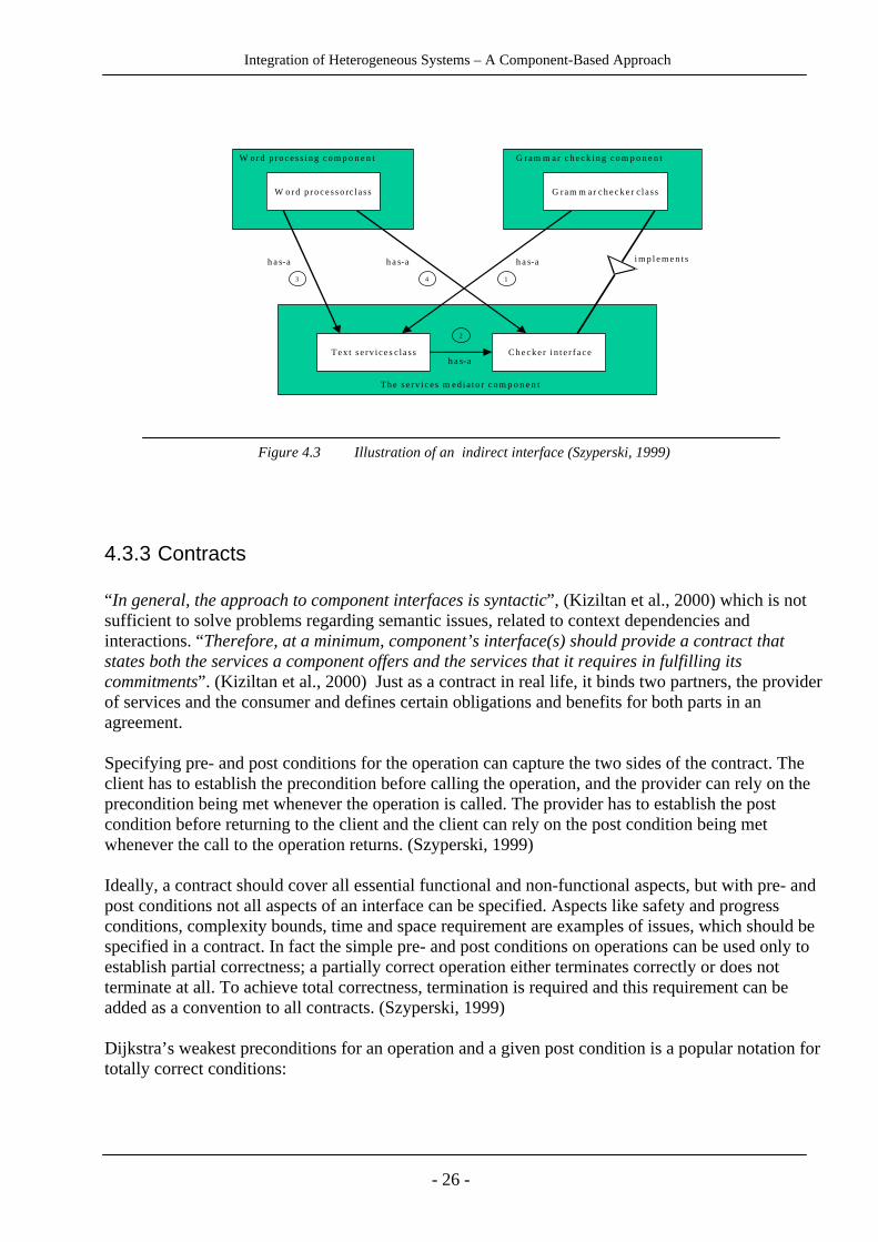
Szyperski gives an example to make this clearer: (Look at the figure 4.3) A word processing clientcalls on services of a grammar checker that is acquired indirectly from a component mediatingbetween clients and providers of text services. First, the grammar checker knows about the textservice mediator. Secondly, the grammar checker registered itself as the default checker with themediator. The mediator knows only about the abstract checker interface. Thirdly, the word processorknows about the mediator. Fourthly, the word processor acquires a reference to the current defaultchecker from the mediator. Just as the mediator, the word processor, knows only the abstract checkerinterface.
Integration of Heterogeneous Systems – A Component-Based Approach
- 26 -
W o r d p r o c e s s i n g c o m p o n e n t G ram m a r c h e c k i n g c o m p o n e n t
W o r d p r o c e s s o r c la s s
T e x t s e r v i c e s c la s s C h e c k e r i n t e r f a c e
T h e s e r v i c e s m e d i a t o r c o m p o n e n t
h a s - a
G ram m ar c h e c k e r c la s s
h a s - a
h a s - a h a s - a 1
2
3 4 i m p l e m e n t s
Figure 4.3 Illustration of an indirect interface (Szyperski, 1999)
4.3.3 Contracts
“In general, the approach to component interfaces is syntactic”, (Kiziltan et al., 2000) which is notsufficient to solve problems regarding semantic issues, related to context dependencies andinteractions. “Therefore, at a minimum, component’s interface(s) should provide a contract thatstates both the services a component offers and the services that it requires in fulfilling itscommitments”. (Kiziltan et al., 2000) Just as a contract in real life, it binds two partners, the providerof services and the consumer and defines certain obligations and benefits for both parts in anagreement.
Specifying pre- and post conditions for the operation can capture the two sides of the contract. Theclient has to establish the precondition before calling the operation, and the provider can rely on theprecondition being met whenever the operation is called. The provider has to establish the postcondition before returning to the client and the client can rely on the post condition being metwhenever the call to the operation returns. (Szyperski, 1999)
Ideally, a contract should cover all essential functional and non-functional aspects, but with pre- andpost conditions not all aspects of an interface can be specified. Aspects like safety and progressconditions, complexity bounds, time and space requirement are examples of issues, which should bespecified in a contract. In fact the simple pre- and post conditions on operations can be used only toestablish partial correctness; a partially correct operation either terminates correctly or does notterminate at all. To achieve total correctness, termination is required and this requirement can beadded as a convention to all contracts. (Szyperski, 1999)
Dijkstra’s weakest preconditions for an operation and a given post condition is a popular notation fortotally correct conditions:

Integration of Heterogeneous Systems – A Component-Based Approach
- 27 -
The predicate Wp(C, R) is true in the state s if and only if every execution of C, which begins in s,leads to a state, in which R is satisfied. Wp(i:=i+1, i>0) ≡ i>-1 (Holström, 1990)
4.3.4 Design Patterns and Frameworks
The basic idea of using patterns is borrowed from work done in building architecture to describequalities for good architectural designs. In the seventies, the architect Christopher Alexander startedusing pattern languages to describe the events and forms that appeared in cities, towns, and buildingsin the world at large. He saw similarities in architectural structures, the problem of constructing themand the solution to construct them well. He showed that many of the problems in architectural designcould be represented as design patterns. Alexander wrote “Each pattern describes a problem whichoccurs over and over again in our environment, and then describes the core of the solution to thatproblem, in such a way that you can use this solution a million times over, without ever doing it thesame way twice”. (Larsson & Sandberg, 2000) Each building is unique, yet all buildings share manyfeatures.
Software development presents an analogous situation. Independently developed software systemsoften share common elements of an architectural structure. The connection between Alexander'spatterns and software architecture has led many in the software community to argue for a higher-level organizing principle in software than that of objects and classes and thereby much of thesediscussions logically centres on software component design, where it is natural to discussinteractions between entities.
Erich Gamma, Richard Helm, Ralph Johnson, and John Vlissides define design patterns as"descriptions of communicating objects and classes that are customized to solve a general designproblem in a particular context. …A design pattern names, abstracts, and identifies the key aspectsof a common design structure that make it useful for creating a reusable object-oriented design. Thedesign pattern identifies the participating classes and their instances, their roles and collaborations,and the distribution of responsibilities. Each design pattern focuses on a particular object-orienteddesign problem or issue. It describes when it applies, whether or not in can be applied in view ofother design constraints, and the consequences and trade-offs of its use. Since we must eventuallyimplement our designs, a design pattern also provides sample ... code to illustrate animplementation. Although design patterns describe object-oriented designs, they are based onpractical solutions that have been implemented in mainstream object-oriented programminglanguages.... “ (Gamma et al., 1995)
Another concept closely related to patterns is frameworks. A framework defines a certain group ofparticipants and relations between them as a highly reusable design for an application, or part of anapplication, in a certain domain. (Kiziltan et al., 2000) According to Gamma et al. the frameworkdictates the architecture of an application. It will define the overall structure, its partitioning intoclasses and objects, the key responsibilities thereof, how the classes and objects collaborate, and thethread of control. (Gamma et al., 1995)
A framework is different from a design pattern. While design patterns are microarchitectures, whichdescribe the abstract interaction between objects collaborating to solve a particular problem, aframework is a concrete powerful solution that can be described in source code. Only examplesusage or applications of a design pattern can be described in source code. Furthermore, a framework

Integration of Heterogeneous Systems – A Component-Based Approach
- 28 -
is often built by the application of a number of design patterns, and thus, patterns describemicroarchitectures often used in frameworks. (Larsson & Sandberg, 2000)
Gamma et al. (1995) list the following differences between patterns and frameworks:
• Design patterns are more abstract. Frameworks are partial implementations of subsystems,while patterns have no immediate implementation at all; only examples of patterns can befound in implementations.
• Design patterns are smaller architectural elements than frameworks. A typical frameworkcontains several design patterns, but the reverse is never true.
• Design patterns are less specialized. Frameworks always have a particular applicationdomain.
A problem with using frameworks in practical development is to determine the level of detail, atwhich the framework should be defined. Finding the proper boundaries and granularity for aframework is a crucial and hard task. A high level of rigidness, limits the use of the framework andwould risk to rule out certain target domains. A high level of flexibility, on the other hand, increasescomplexity and makes it inefficient in usage.
What is the relationship between components and these architectural elements? Actually as the figure4.4 shows, one or more design patterns can be applied to build a component, but also, as a realizationof a design pattern, one or more components can be used. Furthermore, components can be used asparts in for example a framework and a framework can be viewed as the glue code that makescomponents work together. In fact, technologies like JavaBeans, COM/DCOM or CORBA, aredifferent specialized frameworks making it possible to connect components. (Larsson & Sandberg,2000)
Figure 4.4 Relationships between Patterns, Frameworks and Components (Larsson & Sandberg, 2000)
Design Pattern Components
Frameworks
0..n
0..n0..n 0..n
0..n

Integration of Heterogeneous Systems – A Component-Based Approach
- 29 -
4.4 Activities of the Component-Based Development Approach
Development with components differs from the traditional development. In component-baseddevelopment, the notion of building a system by writing code has been replaced with building asystem by assembling and integrating existing software components. In contrast to traditionaldevelopment, where system integration is often the tail end of an implementation effort,component integration is the centrepiece of the approach; thus, implementation has given way tointegration as the focus of system construction. Because of this, integrability is a keyconsideration in the decision whether to acquire, reuse, or build the components.
As depicted in figure 4.5, four major activities characterize the component-based developmentapproach:
• Component qualification (sometimes referred to as suitability testing)
• Component adaptation
• Assembling components into systems
• System evolution
The vertical partitions shown in figure 4.5 describe the central artefact of component-basedsystems – the component – in various states. These are:
• Off-the-shelf components have “hidden interfaces” (not fit for use). They comefrom a variety of sources; some developed in-house (perhaps used in a previousproject), others specifically purchased from commercial vendor.
• Qualified components have discovered interfaces so that possible sources ofconflict and overlap have been identified.
Figure 4.5 Activities of the Component-Based Development Approach (Brown, 1996)

Integration of Heterogeneous Systems – A Component-Based Approach
- 30 -
• Adapted components have been amended to address potential sources of conflict.The figure implies a kind of component “wrapping”, but other approaches arepossible, like the use of mediators and translators.
• Assembled components have been integrated into an architectural infrastructure.This infrastructure will support component assembly and co-ordination.
• Updated components have been replaced by newer versions, or by differentcomponents with similar behaviour and interfaces. Often this requires wrappers tobe rewritten, and for well-defined component interfaces to reduce the extensivetesting needed to ensure operation of unchanged components is not adverselyeffected. (Brown, 1996)
And now a description of the major activities in component-based development according toCarnegie Mellon, Software Engineering Institute (2000):
• Component qualification is a process of determining "fitness for use" of previouslydeveloped components that are being applied in a new system context. Componentqualification is also a process for selecting components when a marketplace of competingproducts exists. Qualification of a component can also extend to include qualification ofthe development process used to create and maintain it (for example, ensuring algorithmshave been validated, and that rigorous code inspections have taken place). There are twophases of component qualification: discovery and evaluation. In the discovery phase, theproperties of a component are identified. Such properties include componentfunctionality (what services are provided) and other aspects of a component's interface(such as the use of standards). These properties also include quality aspects that are moredifficult to isolate, such as component reliability, predictability, and usability. In somecircumstances, it is also reasonable to discover "non-technical" component properties,such as the vendor's market share, past business performance, and process maturity of thecomponent developer's organization. Discovery is a difficult and ill-defined process, withmuch of the needed information being difficult to quantify and, in some cases, difficult toobtain. There are some relatively mature evaluation techniques for selecting from amonga group of peer products. For example, the International Standards Organization (ISO)describes general criteria for product evaluation while others describe techniques thattake into account the needs of particular application domains. These evaluationapproaches typically involve a combination of paper-based studies of the components,discussion with other users of those components, and hands-on benchmarking andprototyping. One recent trend is toward a "product line" approach that is based on areusable set of components that appear in a range of software products. This approachassumes that similar systems (e.g., most radar systems) have similar software architectureand that a majority of the required functionality is the same from one product to the next.The common functionality can therefore be provided by the same set of components, thussimplifying the development and maintenance life cycle.
• Component adaptation: Because individual components are written to meet differentrequirements, and are based on differing assumptions about their context, componentsoften must be adapted when used in a new system. Components must be adapted based

Integration of Heterogeneous Systems – A Component-Based Approach
- 31 -
on rules that ensure conflicts among components are minimized. The degree to which acomponent's internal structure is accessible suggests different approaches to adaptation:
o White box, where access to source code allows a component to be significantlyrewritten to operate with other components.
o Grey box, where source code of a component is not modified but the componentprovides its own extension language or application programming interface (API).
o Black box, where only a binary executable form of the component is available andthere is no extension language or API.
Each of these adaptation approaches has its own positives and negatives; however, whitebox approaches, because they modify source code, can result in serious maintenance andevolution concerns in the long term. Wrapping, bridging, and mediating are specificprogramming techniques used to adapt grey- and black-box components.
• Assembling components into systems: Components must be integrated through some well-defined infrastructure or frameworks. These architectural styles provide the bindings thatform a system from the disparate components.
• System evolution: Component-based systems seem relatively easy to evolve and upgradesince components are the unit of change. To repair an error, an updated component isswapped for its defective equivalent, treating components as plug-replaceable units.Similarly, when additional functionality is required, it is embodied in a new componentthat is added to the system. However, this is a rather simplistic view of system evolution.Regarding today’s component technology, replacement of one component with another isstill a time-consuming and arduous task since the new component will never be identicalto its predecessor and must be thoroughly tested, both in isolation and in combinationwith the rest of the system. Wrappers must typically be rewritten, and side effects fromchanges must be found and assessed.

Integration of Heterogeneous Systems – A Component-Based Approach
- 32 -
5 Integration principles
In this section, we will study what integration principles could be suitable for softwarecomponent integration.
5.1 Introduction
According to systems theory a system is defined as “ an organised or complex whole; anassemblage or combination of things or parts forming a complex or unitary whole.” With thesame spirit integration is defined as the “act or process of making whole or entire, to bring partstogether into a whole”. (Johnson et al., 1973) The vitalist theory of deduction or philosophicalreasoning proposes the following points regarding principles of integration:
• The whole is primary and the parts are secondary.
• Integration is the condition of the interrelatedness of the many parts within one.
• The parts so constitute an indissoluble whole that no parts can be affected withoutaffecting all other parts.
• Parts play their role in light of the purpose for which the whole exists.
• The nature of the part and its function is derived from its position in the whole and itsbehaviour is regulated by the whole to part relationship.
• The whole is any system or complex or configuration of energy and behaves like a singlepiece no matter how complex.
• Everything should start with the whole as a premise and the parts and their relationshipsshould evolve.
(Johnson et al., 1973)
Now it will be helpful to define systems more precisely as “an array of components designed toaccomplish a particular objective according to plan”. (Johnson et al., 1973) Note that there arethree significant points in the definition:
• Purpose or objective which, the system is designed to perform.
• Design or an established arrangement of the components.
• Plan, which inputs of information, energy, and materials must be allocated in accordancewith.
Regarding these points, the definition of integration - to make into a whole; unify, to join withsomething else, and unite – holds true when considering the phrase "system integration". Systemintegration involves taking a number of disparate components and engineering each component
Integration of Heterogeneous Systems – A Component-Based Approach
- 33 -
to integrate with all others. The Institute for Telecommunication Science defines systemintegration as “The progressive linking and testing of system components to merge theirfunctional and technical characteristics into a comprehensive, interoperable system. Integrationof data systems allows data existing on disparate systems to be shared or accessed acrossfunctional or system boundaries”. (Institute for Telecommunication Science, 1996)
Let us transfer the discussion to the world of information systems. An information systemaccording to Andersen is a system for gathering, processing, storing and transferringinformation. This system can be performed in part or as a whole by computers. The part of theinformation systems that is being performed by computers is called software system. Langeforsdescribes a software system as constituted by two parts, the informal and the formal part. Theinformal part contains issues such as required information and how the software solutionaddresses user-issues. The formal part contains issues such as data storage and computerinstructions. (Christiansson & Jakobsson, 2000) Although almost everything mentioned aboveregarding definitions and principles has correspondence in the world of software systems, theessence of the integration concept in this world is to challenge some of the principles above,especially the third one, which is “the parts so constitute an indissoluble whole that no parts canbe affected without affecting all other parts”. Up to now the traditional way of systemdevelopment have led to information systems, which are characterized of hard coupling,unchangeability, inflexibility, and isolation (information island phenomenon). (Magoulas &Pessi, 1998) Every effort of modification of a system to satisfy and manage new needs andsituations is a very complex task, demanding long time and high level of costs.
The selection of a particular architectural style, or the invention of a custom style, is perhaps themost important design decision affecting the integration process. In fact, the architecture willdrive the integration effort.
According to Bass, Clements, and Kazman the software architecture of a program or computingsystem is the structure or structures of the system, which comprise software components, theexternally visible properties of those components, and the relationships among them. By"externally visible" properties, means those assumptions other components can make of acomponent, such as its provided services, performance characteristics, fault handling, sharedresource usage, and so on. (Carnegie Mellon, Software Engineering Institute, 2001) There arefour essential points in this definition:
• Architecture defines components. The architecture embodies information about how thecomponents interact with each other. This means that architecture specifically omitscontent information about components that does not pertain to their interaction.
• The definition makes clear that systems can comprise more than one structure, and thatno one structure holds the irrefutable claim to being the architecture. By intention, thedefinition does not specify what architectural components and relationships are. Is asoftware component an object? A process? A library? A database? A commercialproduct? It can be any of these things and more.
• The definition implies that every software system has architecture, because every systemcan be shown to be composed of components and relations among them.
• The behaviour of each component is part of the architecture, insofar as that behaviour canbe observed or discerned from the point of view of another component. This behaviour is

Integration of Heterogeneous Systems – A Component-Based Approach
- 34 -
what allows components to interact with each other, which is clearly part of thearchitecture.
(Carnegie Mellon, Software Engineering Institute, 2001)
Generally, integration involves a relationship between entities. Regarding this and the definitionabove, in the component based software systems, integration is very much a matter ofarchitecture. In fact there are integration architectures. (Isazadeh et al., 1995)
A software integration architecture is a general pattern that serves as a blueprint to define thebasic layout of an integrated system. It has to deal with bottom-up integration of existingcomponents as well as the development of new components for top-down integration (pre-factointegration). Integration architecture describes the general strategy of system decomposition, datastorage, and communications. The architecture should not be concerned with the internalstructure of the components. A software component within the integration architecture, therefore,should be monolithic, i.e., allow no access to its internal structure. (Isazadeh et al., 1995)
According to our interpretation of studying Isazadeh et al.(1995), Christiansson & Jakobsson(2000) and Szyperski (1999) there are the following major issues concerning integrationarchitectures:
• Design and composition: what is to be put together and how?
• Managing dynamic situations
• Analysing and managing complex situations
• Communication
We believe that one of the difficulties in integration efforts is the lack of a higher-level andexplicit representation of interaction between components, which can be provided by designpatterns. With help of design patterns you can collect and abstract common patterns ofbehaviours and make them explicit and general and thereby get a clear and good high-level viewover the interaction between the involved components. This means that the integrator gets morepower to manage dynamism, complexity and solving communication issues in the composedsystem.
5.2 Design patterns
As we earlier mentioned, a design pattern is a description of a suggested solution to a generaldesign problem that may occur in many different situations. Their purpose is to serve softwareengineers in designing, by using well-proven solutions to their design problems, and to give thema common design vocabulary, that facilitates communication of a specific design. (Hnich,Jonsson & Kiziltan, 1999)
A design pattern is often described as constituted of four elements: a pattern name, a problemelement which describes in which problem contexts the pattern is applicable, a solution elementwhich describes the suggested solution in terms of elements, their relationships, responsibilities

Integration of Heterogeneous Systems – A Component-Based Approach
- 35 -
and collaborations and a consequences element, which describes the results and trade-offs ofapplying the pattern. (Gamma et al., 1995)
Gamma et al. (1995) describe 23 different design patterns for use in design of object-orientedsoftware. They divide these design patterns into three categories: creational, structural andbehavioural patterns. The creational design patterns describe how to abstract the instantiationprocess of objects, the structural design patterns are concerned with how classes and objects arecomposed to form larger structures and the behavioural design patterns are concerned withalgorithms and the assignment of responsibilities between objects. We believe that some of thestructural and behavioural patterns could be applied to the area of component-baseddevelopment, for use in integrating components. Here follows a description of each of thesepatterns.
5.2.1 Adapter
An adapter, as explained by Gamma et al. (1995) converts the interface of a class into anotherinterface that the clients expect, thereby making it possible for classes with incompatibleinterfaces to communicate. Another name for this pattern is wrapper. The clients of a class thatuses an adapter, will make requests to the adapter instead of the class. The adapter translates therequest to a form that can be understood by the class and then sends this request to the class.
This pattern could be applied at a component-level, where the adapter converts the interface of acomponent (see figure 5.1). By using an adapter, no changes need to be done in the existingcomponent or its clients, to enable communication between them. The term client here couldrepresent other components.
The adapter could be used when using COTS-components that have interfaces that do not matchthe interfaces that the existing components expect.
Adapters can vary in the amount of work they do to adapt a class/component to its clients. Insome cases, the adapter simply needs to change the names of the operations and sometimes acompletely different set of operations may need to be supported. This variation depends on thedifference between the component’s interface and the expected interface. (Gamma et al, 1995)
Introducing an adapter to a system’s architecture means that every request to the wrappedcomponent will be performed in two steps, and might result in decreased performance orreliability. (Gamma et al., 1995)
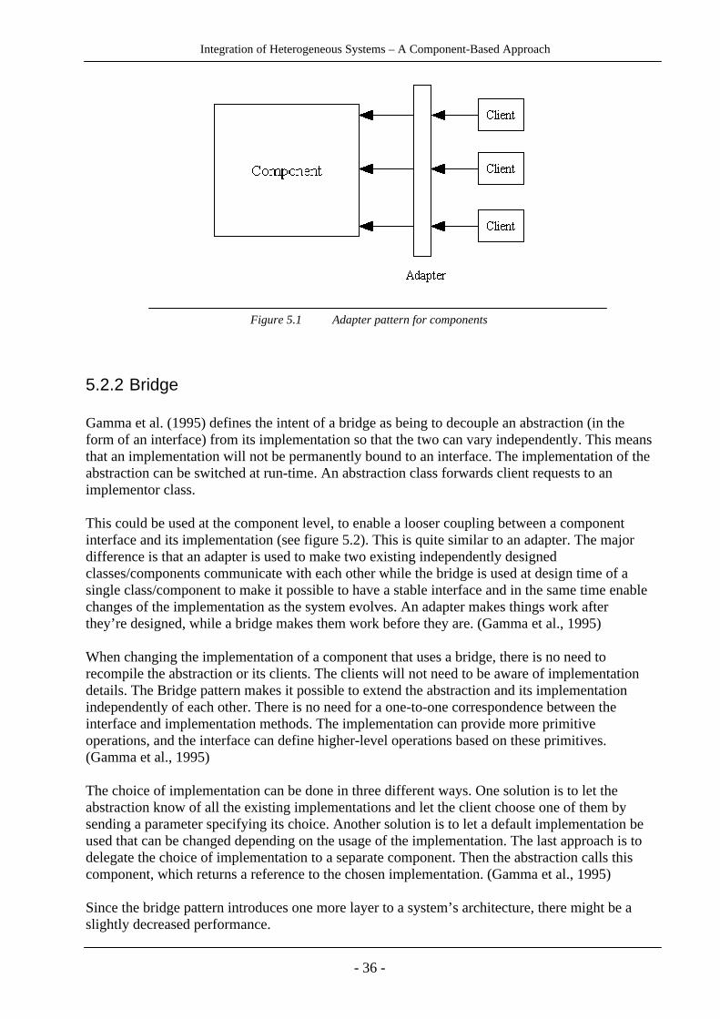
Integration of Heterogeneous Systems – A Component-Based Approach
- 36 -
Figure 5.1 Adapter pattern for components
5.2.2 Bridge
Gamma et al. (1995) defines the intent of a bridge as being to decouple an abstraction (in theform of an interface) from its implementation so that the two can vary independently. This meansthat an implementation will not be permanently bound to an interface. The implementation of theabstraction can be switched at run-time. An abstraction class forwards client requests to animplementor class.
This could be used at the component level, to enable a looser coupling between a componentinterface and its implementation (see figure 5.2). This is quite similar to an adapter. The majordifference is that an adapter is used to make two existing independently designedclasses/components communicate with each other while the bridge is used at design time of asingle class/component to make it possible to have a stable interface and in the same time enablechanges of the implementation as the system evolves. An adapter makes things work afterthey’re designed, while a bridge makes them work before they are. (Gamma et al., 1995)
When changing the implementation of a component that uses a bridge, there is no need torecompile the abstraction or its clients. The clients will not need to be aware of implementationdetails. The Bridge pattern makes it possible to extend the abstraction and its implementationindependently of each other. There is no need for a one-to-one correspondence between theinterface and implementation methods. The implementation can provide more primitiveoperations, and the interface can define higher-level operations based on these primitives.(Gamma et al., 1995)
The choice of implementation can be done in three different ways. One solution is to let theabstraction know of all the existing implementations and let the client choose one of them bysending a parameter specifying its choice. Another solution is to let a default implementation beused that can be changed depending on the usage of the implementation. The last approach is todelegate the choice of implementation to a separate component. Then the abstraction calls thiscomponent, which returns a reference to the chosen implementation. (Gamma et al., 1995)
Since the bridge pattern introduces one more layer to a system’s architecture, there might be aslightly decreased performance.

Integration of Heterogeneous Systems – A Component-Based Approach
- 37 -
Figure 5.2 Bridge pattern for components
5.2.3 Proxy
A proxy provides a “surrogate or placeholder for another object to control access to it” (Gammaet al., 1995). It could be seen as a middleman that manages the communication with a target. Itcontrols access to the target and has an interface that is identical (or a subset) to the interface ofthe target.
The proxy design pattern is widely used in infrastructures for distributed systems to representremote components (see figure 5.3). This pattern makes clients communicate with arepresentative rather than with the component itself.
A proxy could be used to avoid hard coding physical location into the client. It can also be usedto provide access control to the component and may for example give different clients differentaccess rights. When used for access control the proxy might provide an interface that is a subsetof the component’s interface. (Gamma et al., 1995)
The benefit of using a proxy for remote communication is that it decouples clients from thelocation of remote server components. The proxy becomes responsible for encoding requests andtheir arguments and for sending the requests to the remote component in a different addressspace.
The proxy pattern might lead to less efficiency due to indirection and the implementation couldbecome complex.

Integration of Heterogeneous Systems – A Component-Based Approach
- 38 -
Figure 5.3 Proxy pattern for components
5.2.4 Mediator
The mediator design pattern describes a central connection point that controls the interactionbetween a set of objects. The mediator functions as a middleman, that provides a looser couplingbetween the objects, since the objects will not have to explicitly refer to each other. The objectsonly know the mediator and send all their request to this central hub. (Gamma et al., 1995)
The mediator could at a component-level be a component that manages the interaction between aset of components that have well-defined but complex interdependencies (see figure 5.4). Thecomponents will send and receive requests to the mediator. The mediator forwards the requeststo the appropriate target component.
A mediator centralizes behaviour management to a central hub. The communication pathwaysdecrease since there will be one-to-many communication between the mediator and thecomponents, instead of one-to-one communication between every component-pair that needs tointeract. For example, in a system with N components, where every component needs to interactwith every other component, there will be N*(N-1) dependencies without a mediator and 2*Ndependencies with a mediator. This means that the components will be more loosely coupled toeach other when using a mediator, which facilitates easy replacement and reuse of components.
By letting a central hub manage the interaction between the components, the interactionbehaviour is separated from the individual components’ behaviour, which could give a moreclear view of the system as a whole. A problem with using the mediator pattern is that since themediator manages all the interaction between the components, this component could easilybecome very complex and hard to maintain. (Gamma et al., 1995)
Another problem we could see with this pattern is that since the mediator is the only connectionpoint between the components, the architecture becomes heavily dependent on the mediator. Ifthe mediator does not function, no components will be able to send and receive request among

Integration of Heterogeneous Systems – A Component-Based Approach
- 39 -
each other. The performance and reliability of the mediator component will have a deep impacton the functioning of the system as a whole.
Figure 5.4 Mediator pattern for components
5.2.5 Facade
Facade is a design pattern that gives a high-level interface to a set of interfaces in a subsystem, tomake the subsystem easier to use and to shield clients from the inner parts of the subsystem. Thepurpose of the facade is to provide a simple view of the subsystem that will be enough for mostclients. Only those clients, who need more customizability, will have to look beyond the facade.(Gamma et al., 1995)
The facade pattern could be used for components, to provide a simple interface to a component’sclients (see figure 5.5). The clients interact with the component by sending requests to thefacade, which forwards them to the appropriate part of the component. The facade will be a partof the component’s public interface, but there will also be other interfaces that provide a directentry point to different parts of the component for clients with more specialized needs.
The facade is useful when there are many dependencies between different parts of a componentand its clients. A facade provides weak coupling between the component and its clients, whichmean changes can be made within the component without affecting the clients. The facade couldbe used for layering, where the facade functions as a single entry-point to each layer-level.(Gamma et al., 1995)
A drawback of using a facade is that it might not give full possibilities of using all functionalityinside a component, so it might not be useful for all clients. Since a facade does not preventclients from directly making requests to the inner parts of the component, those clients whoaccess the component through other interfaces will still have to be considered when makingchanges to the component.

Integration of Heterogeneous Systems – A Component-Based Approach
- 40 -
Figure 5.5 Facade pattern for components
5.2.6 Other patterns
Architectural patterns
In their book “Pattern-Oriented Software Architecture”, Buschmann, Meunier, Rohnert,Sommerlad and Stal (1996) present 16 patterns divided into architectural and design patterns.Many of the patterns are similar to the design patterns described by Gamma et al. (1995). Twoarchitectural patterns that differ from the patterns described by Gamma et al. and that could beuseful for component integration are:
Broker
The Broker pattern can be used to coordinate communication in distributed software systemswith decoupled components. It consists of six types of components: clients, servers, brokers,bridges, client-side proxies and server-side proxies. (OpenLoop, 2000a)
A server implements services that expose their functionality through interfaces consisting ofoperations and attributes. The server registers itself with the local broker and receives requestsfrom clients and sends back responses and exceptions through a server-side proxy. The clientimplements user functionality and sends requests to servers through a client-side proxy andreceives responses and exceptions. Clients do not know about the location of the servers. Abroker registers and locates servers. It offers an interface to clients and servers, and transmits therequests from clients to servers and the responses and exceptions from the servers back to clients.

Integration of Heterogeneous Systems – A Component-Based Approach
- 41 -
If a request is made to a server hosted by another broker, it forwards the request to that broker(see Figure 5.6). (OpenLoop, 2000a)
A client-side proxy constitutes a layer between clients and the broker. It makes remote serversappear as local to the clients, by hiding implementation details like the message transfer betweenthe broker and the client. A server-side proxy is analogous to the client-side proxy for the server-side. It mediates between the server and the broker. It receives requests, unpacks messages andcalls the appropriate service in the server. A bridge is used to bridge communication amongdifferent brokers. It encapsulates network-specific functionality. A bridge mediates between thelocal broker and the bridge of a remote broker. (OpenLoop, 2000a)
The broker pattern provides location transparency, which means that clients do not care whereservers are located and vice versa. Server implementations can be changed without affecting theclients as long as the interface is not changed. Changes to internal broker implementation doesnot affect clients and servers. Different broker systems may interoperate if they have a commonprotocol for the exchange of messages. The fault tolerance and efficiency compared to non-distributed software will be lower. (OpenLoop, 2000a)
Figure 5.6 Broker pattern (where a client calls a server hosted by a remote broker)
Layer
The Layer pattern structures a system into a number of layers that represent different levels ofabstraction. A layer provides services to the layer directly above, and uses services from thelayer directly below. This pattern is useful when building a system that consists of a mix ofcomponents managing high- and low level issues, where the high-level components make use ofthe lower-level components (see figure 5.7). (OpenLoop, 2000b)
This way of integrating components keep dependencies more local – for each layer there is onlythe layer above that uses its services. When changing the interface of a component, onlycomponents in the above layer might need to be changed. Layering supports easy reuse of layers.Efficiency might be affected and it could be difficult to decide the appropriate number of layersfor a system. (Mathiassen, Munk-Madsen, Nielsen & Stage, 1998; OpenLoop, 2000b)

Integration of Heterogeneous Systems – A Component-Based Approach
- 42 -
Figure 5.7 Layer pattern
Component Interaction Patterns
Eskelin (1999) describes five patterns, called Component Interaction Patterns: AbstractInteraction, Component Bus, Component Glue, Third-Party Binding and Consumer-Producer.The patterns deal with the problem of assembling components to communicate, collaborate andcoordinate in a flexible and effective way.
• Abstract interaction is a pattern that reduces a component’s dependence on its environmentby defining interaction protocols between components separately from the components itself.The interactions are specified in terms of abstract interfaces and implemented as a separatecomponent through which all the communication between the components is directed.
• The Component bus pattern manages the routing of information between participatingcomponents, from those that produce information to those that consume it. Each participantcan dynamically attach and detach to and from the bus without effecting the integrity ofothers. When a component is attached to the bus, it registers interest in the information itrequires. When a component places information onto the bus, it is delivered to theparticipants that registered interest for the information. All components communicate withthe interface of the bus.
• Component glue is a design pattern that solves component incompatibilities by using ascripting language to create “glue” code that mediates or adapts between components. Gluecode ties components together without increasing coupling and is an alternative to the adapterpattern. Glue code is not implemented as components, unless the same glue code is used inmany parts of a system.

Integration of Heterogeneous Systems – A Component-Based Approach
- 43 -
• Third-party binding makes connections among components explicit and separate, by havinga third component bind two interacting components together.
• The Consumer-Producer pattern introduces a producer component that acts as a single,generic interface to different core system services like heterogeneous databases, naming anddirectory services. The consumers are the clients that use these services. A service providerinterface is defined that allows programmers building service providers to conform to theproducer and allow consumers to access their service.

Integration of Heterogeneous Systems – A Component-Based Approach
- 44 -
6 Integration techniques
In this section, we will study various techniques for integrating software components. We willgive a detailed presentation of the three dominating techniques in this area, and also a briefoverview of some other techniques, which may get a significant portion of the market in thefuture.
6.1 Dominating techniques
There are three dominating techniques in the area of software component integration, namelyEnterprise JavaBeans from Sun, COM from Microsoft and CORBA from the ObjectManagement Group. In this section, we will present their architectures in a detailed level.
6.1.1 Enterprise JavaBeans
Enterprise JavaBeans defines a set of services and APIs for server-side Java components,promising hardware and operating system independence for component architecture. It is anextension of the JavaBeans-architecture, which will be described first in the following.
JavaBeans
The Java Development Kit (JDK) 1.1 released in February 1997, had a new API calledJavaBeans. JavaBeans is the portable, platform-independent, component architecture for the Javaapplication environment, which allows applications to be assembled from ready – madecomponents, known as beans. It is intended for use in developing or assembling network-awaresolutions for heterogeneous environment – within an enterprise or throughout the Internet. (Jia,2000)
JavaBeans is an attempt to provide a standard for creating objects that have expected anddocumented behaviour. That is originally an initiative from Sun Microsystems but severalcompanies such as Apple, Borland, IBM, Microsoft and Netscape have been involved in thespecification. Software that adheres to the JavaBean specification will publish information aboutitself onto an Integrated Development Environment (IDE). IDEs usually consist of a compiler,debugger and a graphical development environment. Symantec Café and Java Workshop areexamples of IDEs. The IDE can then present the developer with the object’s attributes as well asnotify the developer of events that the object will respond to. (Schneider & Arora, 1997)
The JavaBeans initiative is a family of specifications as well as some basic classes that facilitatewriting Java Components. A bean is a reusable software component that can be developed in avisual tool builder. Creation of beans is done with a package called java.beans and a BeansDeveloper Toolkit. (Schneider & Arora, 1997)
Software components hide implementation, conform to interfaces, and encapsulate data, just likeclasses do in object-oriented languages. So how do components differ from classes? The answer

Integration of Heterogeneous Systems – A Component-Based Approach
- 45 -
is: almost all software components consist of classes. What makes them components is theirconformance to a software component specification. The JavaBeans Specification is thedocument that describes what a Java class must do to be considered a "Bean." Programmers (and,as importantly, integrated development environments [IDEs]) can depend on any class thatadvertises itself as a Bean to conform to the rules set out in the specification. If it doesn'tconform, the contract has been broken and the Bean is defective. (Johnson, 1997)
One of the requirements to make a class into a Bean is that the class implements the interface“java.io.Serializable”. Serializable classes know how to package themselves into streams ofbytes to be transmitted through networks or saved to disk, awaiting later reincarnation.
Interfaces and classes defined in the package “java.beans” allow a Beans developer to controlhow the Beans user (a programmer using a particular Bean) may set and get Beans' properties,hook Beans up to communicate with other components, and ask Beans to describe themselves.The component specification outlines how the component must implement these methods.(Johnson, 1997)
JavaBeans is not a product, program, or development environment. It is both a core Java package(java.beans) that Beans may use to provide extended functionality, and a document (theJavaBeans Specification) that describes how to use the classes and interfaces in the java.beanspackage to implement "Beans functionality." (Johnson, 1997)
JavaBeans turns classes into software components by providing several new features. Some ofthese features are specific to Beans. Others, like serialization, can apply to any class, Bean orotherwise, but are crucial to the understanding and use of Beans.
There are five features that are common for most JavaBeans:
• Introspection: enables a builder tool to analyse how a bean works.
• Customization: enables a developer to customise the appearance and behaviour of a bean.
• Events: enables beans to communicate and connect together.
• Properties: enables developers to program with beans
• Persistence: enables developers to customize beans and then retrieve those beans withcustomized features for future use.
Software components have properties, which are attributes of the classes. Customization is theprocess of configuring a Bean for a particular task. The new event handling scheme in Java 1.1was created in part to ease communication between Beans. Beans may be dissected by IDEs orby other classes through a process called introspection. Beans may be persisted (i.e., serialized)into byte streams for transmission or storage, and persisted Beans may be packaged into "JARfiles" to ease downloading and access. Finally, Beans have been designed to interoperate easilywith legacy component technologies such as ActiveX and LiveConnect, and participate intransactions with Object Request Broker systems such as CORBA. (Johnson, 1997)

Integration of Heterogeneous Systems – A Component-Based Approach
- 46 -
Properties and customization
Properties, as noted above, are attributes of a Bean. Visual properties might include colour orscreen size. Other properties may have no visual representation: a BrowserHistory Bean, forexample, might have a property specifying the maximum number of URLs to store. Beansexpose setter and getter methods (called "accessor methods") for their properties, allowing otherclasses or IDEs to manipulate their state. The process of setting up a Bean's properties at design-or runtime is called customization. (Johnson, 1997)
The value of an indexed property is an array. Indexed properties' accessor methods receive andreturn arrays of values instead of scalars. Accessor methods may throw checked exceptions toreport error conditions.
Sometimes it's useful for an action to occur when a certain property of an object changes. Boundproperties cause events to be sent to other objects when the property's value changes, possiblyallowing the receiver to take some action. So, a SpreadSheet Bean might be configured to tell aPieChart Bean to redraw itself whenever the spreadsheet data changes.
Sometimes, certain values for properties are illegal, based on the state of other Beans. A Beancan be set up to "listen" to these constrained properties of other Beans, and "veto" changes itdoesn't like.
When a developer is connecting Beans together to create an application, the IDE can present aproperty sheet containing all the Beans' properties and their current values. (A property sheet is adialog box used to set and/or view properties, like what you get by selecting Options… on amenu.) The developer sets the properties graphically, which the IDE translates into calls to theBeans' setter methods, changing the Beans' state. This customizes the Beans for the particularapplication. The relevant classes for manipulating properties and customization are in thejava.beans package.
Event handling
A pre-condition for all interactions between Beans is some way of communication. JDK 1.1brought a new event model that classes use to communicate. In this event model, a class registersinterest in the activities of another class by way of a listener interface. In effect, the target object(the interested party) tells the source object (the object of interest), "Let me know whenever so-and-so happens." When the so-and-so occurs, the source object "fires" an event at the target byinvoking the target's event handler with a subclass of EventObject as the argument.(Johnson, 1997)
Events can be used to implement bound and constrained properties. In the PieChart andSpreadSheet example above, the PieChart "registers" interest in any change to the SpreadSheet's(let's say) DataList property. When the SpreadSheet is going to change its DataList property, itpasses a DataListChangedEvent (subclassed from EventObject), indicating what changed, toevery interested listener's event handler method. The target (PieChart) then examines the event,and takes appropriate action. In the case with constrained properties, it works similarly; but inthat case, the target vetoes the change by throwing an exception.
Integration of Heterogeneous Systems – A Component-Based Approach
- 47 -
The EventObject class can be extended to create user-defined events. Classes can now define anduse new event types to send messages to one another. This means that Beans running inside thesame container may communicate by passing messages around. This helps uncoupledependencies between objects, which we know is an advantage. User-defined (and other) eventsare derived from the class java.util.EventObject. (Johnson, 1997)
Introspection
It is the name of the process of programmatically analyzing a class's public methods andmembers. This process is also sometimes called discovery. The new reflection mechanism in theJava core, which can dissect an object and return a description of its contents, makesintrospection possible.
The IDE discovers a Bean's properties in one of two ways: by asking the Bean for a descriptionof its properties, or by dissecting the Bean by introspecting it. A typical IDE will start by askinga Bean for a BeanInfo object, which describes the Bean's properties, among other things. TheIDE will then use the BeanInfo object to construct a property sheet. (This is assuming the Beandoesn't provide a customizer of its own.) If the Bean doesn't know how to return a BeanInfoobject, the IDE then introspects the Bean, and scans the list of methods for names beginning withset and get. It assumes (by convention) that these methods are accessors for properties, andcreates a new property sheet based on the accessor methods that exist and the types of thearguments those methods take. So, if the IDE finds methods like setColor(Color), ColorgetColor(), setSize(Size), and Size getSize(), then it will create a property sheet with theproperties Color and Size, and appropriately-typed widgets for setting them. This means that if adeveloper simply follows the conventions for naming accessor methods, an IDE can determineautomatically how to create a customization property sheet for the component. (Johnson, 1997)
The reflection mechanism that performs introspection is in the package “java.lang.reflect”.
Persistence and packaging
It's often useful to "freeze-dry" an object by converting its state into a blob of data to be packedaway for later use -- or transmitted through a network for processing elsewhere. This process iscalled serialization.
One of the simplest uses for serialization is to save the state of a customized Bean, so that anewly-constructed Bean's properties can be correctly set at run time.Also, serialization is a mainstay of component technology, making possible distributed-processing schemes such as CORBA.
Where should a group of freeze-dried Beans that have been "pickled" in this way be kept? Well,in a JAR, of course! The JavaBeans specification describes a JAR file as a structured ZIP filecontaining multiple serialized objects, documentation, images, class files, and so on, with amanifest that describes what's in the JAR. A JAR file, containing many compressed small files,can be downloaded all in one piece and decompressed on the client end, making appletdownloading more efficient. (Johnson, 1997)

Integration of Heterogeneous Systems – A Component-Based Approach
- 48 -
The java.io package provides object serialization. The JavaBeans Specification describes the formatof JAR files.
Interoperation
There are a lot of standards in the area of component technology. For example there are manyexisting systems based on OLE (or its latest incarnation, ActiveX), OpenDoc, and LiveConnect.JavaBeans has been designed to (at least eventually) interoperate with these other componenttechnologies.
It's not realistic to expect developers to abandon existing investments in other technologies andreimplement everything in Java. Since the release of Java 1.1, the first Beans/ActiveX "bridge"kits have become available, allowing developers to link Beans and ActiveX componentsseamlessly into the same application. The Java IDL interface, which allowed Java classes tooperate with existing CORBA systems, came later. (Johnson, 1997)
While the Beans/ActiveX bridge and Java IDL are not part of the standard JavaBeansdistribution, they round out JavaBeans' capabilities as an industrial-strength, open technology forportable component software.
Enterprise Beans
As a development of JavaBeans the first version of Enterprise JavaBeans was released in 1998.Enterprise JavaBeans extends JavaBeans by letting container-based objects communicate witheach other via a network. Containers are software receptacles that know how to communicatewith and manage beans and provide services such as persistence management, transactions,concurrency and security. (Jia, 2000) Enterprise JavaBeans specification defines the EnterpriseJavaBeans component architecture and the interfaces between the Enterprise JavaBeanstechnology enabled server and the component.
An enterprise bean is a server-side software component that can be deployed in a distributedmulti-tier environment. An enterprise bean can comprise one or more Java objects because acomponent may be more than just a simple object. Regardless of an enterprise bean’scomposition, the clients of the bean deal with a single exposed component interface. Thisinterface, as well as the enterprise bean itself, must conform to the Enterprise JavaBeansspecification. The specification requires that the beans expose a few required methods, thesemethods allow the EJB container to manage beans uniformly, regardless of which container thebean is running in. (Roman, 1999)
The client of an enterprise bean could be anything—perhaps a servlet, an applet, or even anotherenterprise bean. In the latter case, a client request to a bean can result in a whole chain of beansbeing called. This is a very powerful idea because a complex bean task can be subdivided,allowing one bean to call on a variety of prewritten beans to handle the subtasks. Thishierarchical concept is quite extensible.
Enterprise beans are very similar to two other types of Java components: applets and servlets:

Integration of Heterogeneous Systems – A Component-Based Approach
- 49 -
• Applets are portable Java programs that can be downloaded from a Web server into a Webbrowser and they typically display user interfaces to the end-users. Applets can bedeployed in a Web page, where the browser’s applet viewer provides a runtime containerfor the applets.
• Servlets are networked components that can be used to extend the functionality of a Webserver. Servlets are request/response oriented, in that they take requests from some clienthost and issue a response back to that host. Servlets can be deployed in a Web server,where the Web server’s servlet engine provides a runtime container for the servlets.
• Enterprise beans are deployed in an application server, where the application serverprovides a runtime container for the Enterprise JavaBeans.
(Roman, 1999)
The real difference between applets, servlets, and enterprise beans is the domain of which eachcomponent type is intended to be a part. Both applets and servlets are well suited to handleclient-side operations, such as rendering graphical user interfaces, performing other presentaion-related logic, and lightweight business logic operations. The client side could be a Web browser(in the case of applets), or a Web server (in the case of servlets). In both cases, the componentsare dealing directly with the end-user. (Roman, 1999)
Enterprise beans are server-side components and they are meant to perform server-sideoperations. Server-side components need to run in a highly available, faulttolerant, transactional,and multi user secure environment. An application server provides this high-end server-sideenvironment for the enterprise beans, and it provides the runtime containment necessary tomanage enterprise beans.
IBM, Sun / Netscape and Oracle provide commercial products that implements the EnterpriseJavaBeans specification. The key features of the Enterprise JavaBeans technology are:
• Enterprise JavaBeans components are written entirely in Java programming language.
• Enterprise JavaBeans components contain business logic only, no system levelprogramming.
• The system level services such as security, threading, persistence are automaticallymanaged by the Enterprise JavaBeans server.
• Enterprise JavaBeans component are fully portable across any Enterprise JavaBeansserver and any Operating System.
(Sun Microsystems, 2000a)
EJB is intended to support distributed, Javabased, enterpriselevel applications, such as businessinformation management systems. Among other things, it prescribes an architecture that definesa standard, vendorneutral interface to information services including transactions, persistence,and security. It thereby permits application writers to develop componentbased implementationsof business processing software that are portable across different implementations of thoseunderlying services. (Sousa & Garlan, 1999)

Integration of Heterogeneous Systems – A Component-Based Approach
- 50 -
One of the most important and prevalent classes of software systems are those that supportbusiness information applications, such as accounting systems and inventory tracking systems.Today these systems are usually structured as multitiered clientserver systems, in whichbusinessprocessing software provides services to client programs, and in turn relies on lowerlevel information management services, such as for transactions, persistence, and security. (SeeFigure 6.1.)
Client
Business Application Software
Persistency Security
Information management
services
Transaction Processing
Figure 6.1 A three-tiered business application (Sousa & Garlan, 1999)
Currently one of the problems with writing such applications software is portability: applicationsoftware must be partially rewritten for each vendor's support facilities because informationmanagement services provided by different vendors often have radically different interfaces.
Additionally, clients of application software are faced with a huge variety of interfaces to thoseapplications. While some differences are inevitable, given that different applications mustprovide different capabilities, one would wish for certain levels of standardization for genericoperations such as creating or deleting business entities (such as accounts). To address thisproblem several vendors have proposed component integration frameworks for this class ofsystem. One of these is Sun Microsystems'Enterprise JavaBeans framework(Sousa & Garlan, 1999)
Sun's “Specification of the Enterprise JavaBeans Architecture”, defines a standard for thirdparties to develop Enterprise JavaBeans deployment environments. Understanding EnterpriseJavaBeans architecture requires comprehension of four entities: servers, containers, componentsand clients.
• The EJB server provides a runtime environment for one or more containers. EJB serversmanage low-level system resources, allocating resources to containers as they are needed.Enterprise JavaBeans servers provide fundamental services like legacy systems for

Integration of Heterogeneous Systems – A Component-Based Approach
- 51 -
containers and the components they contain.
• The EJB container provides a playground where your enterprise beans can run. There canbe many beans running within a container. Bean containers are responsible for managingthe beans running within them. They interact with the beans by calling a few requiredmethods that the bean must expose. Containers may also provide access to a legacysystem. Enterprise JavaBeans containers are the middleman between clients andcomponents at the method call level.
• They handle features like life cycle, transaction and security management for thecomponents. Containers make it possible to manage transactions over different servers andeven different machines.
• Enterprise JavaBeans components contain the actual logic. By implementing someinterfaces the developer can use container provided services. Several components usuallyare deployed in the same container.
(Roman, 2000)
The client program is presented with the same interface for all containers. This makes it simplefor the programmer to use different containers on different servers and on different systems.
Figure 6.2 The relationship between EJB servers and EJB containers (Roman, 1999)
An application running in one of these environments would access information managementservices by requesting them of the EJB server, via the EJB API, in the way prescribed by the EJBspec.
Client Code such as as Servlets or applets
invokes invokes
EJB Container 2 EJB Container 1
EJB Server
Fig2. The relationship between EJB servers and EJB containers (Roman, 1999)
Enterprise Bean 1
Enterprise Bean 2
Enterprise Bean 3
Enterprise Bean 4

Integration of Heterogeneous Systems – A Component-Based Approach
- 52 -
Figure 6.3 illustrates a system with a remote client calling an application that implements somebusiness logic, for which Orders and Accounts are relevant operational entities. In theobjectoriented paradigm, such entities are termed objects. An object can be viewed as a unit thatholds a cohesive piece of information and that defines a collection of operations (implementedby methods) to manipulate it. (Roman, 1999)
According to EJB framework Enterprise Beans must conform to specific rules concerning themethods to create or remove a particular bean, or to query a population of beans for thesatisfaction of some property. Hence, whenever a piece of client software needs to access a bean,it can take some features for granted. (Sousa & Garlan, 1999)
EJB server
Figure 6.3 The EJB server offering access to information management services (Sousa & Garlan, 1999)
It is the job of an EJB server provider to map the functionality that the EJB spec describes intoavailable products and technologies. In version 1.0, released in March 1998, the EJB spec coversthe request of transaction management, persistence and security services. The EJB spec does notregulate how these services are to be implemented, however: they may be implemented by the
ClientApplication ApplicationOrder bean
Accountbean
EJB API
TransactionProcessing
Persistency Security

Integration of Heterogeneous Systems – A Component-Based Approach
- 53 -
EJB server provider, as part of the server, or they may rely on external products, eventuallysupplied by other vendors. Such products, however, are invisible to the beans.(Sousa & Garlan, 1999)
The EJB spec refers to the collection of services that both the beans and the client software useas a container (See figure 6.4). A container provides a deployment environment that wraps thebeans during their lifecycle. Each bean lives within a container. The container supports (directlyor indirectly) all aspects that the bean assumes about the outside world, as defined in the EJBspec. The protocols that regulate the dialog between a bean and its container are termed the beancontract. (Sousa & Garlan, 1999)
Figure 6.4 The EJB container (Sousa & Garlan, 1999)
The container also supports a set of protocols, termed the client contract that regulates the dialogbetween client software and a bean. The client contract defines two interfaces that a client uses tocommunicate with a specific bean.
Both interfaces are created at deploymenttime by specialpurpose tools supplied by the EJBserver provider.
ClientBean
Bean
ClientContract
Bean Contract
TransactionProcessing
Persistency Security
Vendor specific mapping
Standard
Integration of Heterogeneous Systems – A Component-Based Approach
- 54 -
• The Remote Interface, which reflects the functionality of the bean it represents, as itpublishes the socalled business methods of the bean. Each bean has one such interface.
• The Home Interface, which contains the methods for creation and removal of beans, as wellas optional methods for querying the population of beans (finder methods). There is one suchinterface per bean class. (Sousa & Garlan, 1999)
Before we discuss further the matter of different types of interfaces, we should look at somefundamental concepts such as enterprise bean class, EJB object, and home object.
Enterprise Bean Class
An enterprise bean component is not a single monolithic file. A number of files work together tomake up an enterprise bean. An enterprise bean is a complete component, which is made up of atleast two interfaces and a bean implementation class. In other word, you provide your enterprisebean component implementation in an enterprise bean class. This is simply a Java class thatconforms to well-defined interfaces, obeys certain rules, and contains implementation details ofyour component. A session bean implementation is very different from an entity beanimplementation. For session beans, an enterprise bean class typically contains business-process-related logic, for example logic to compute prices and transfer funds between bank accounts. Forentity beans, it contains data-related logic, for example logic to change a customer’s name andreduce the balance of a bank account. The EJB specification defines a number of standardinterfaces that bean classes can implement. These interfaces force bean classes to expose certainmethods, which will be called by containers to manage the beans and alert them to significantevents. The most basic interface is the javax.ejb.EnterpriseBean interface. This is a markerinterface, which indicates that the class is indeed an enterprise bean class. It extendsjava.io.Serializable, which means that the class can be converted to a bit-blob and shares allproperties of serializable objects. However the enterprise bean class never needs to implementthe javax.ejb.EnterpriseBean interface directly. It implements the interface corresponding to itsbean type, which is javax.ejb.SessionBean or javax.ejb.EntityBean. (Roman, 1999)
EJB Object
When a client wants to use an instance of an enterprise bean class, the client never invokes themethod directly on an actual bean instance. The invocation is intercepted by the EJB containerand then delegated to the bean instance. There are two important reasons for this. First of all, theenterprise bean class cannot be called across the network directly because this is not network-enabled. The EJB container handles networking by wrapping the bean in a network-enabledobject. This object receives calls from clients and delegates these calls to instances of the beanclass. For the second, by intercepting requests, the EJB container can automatically performsome necessary management, such as transaction logic, security logic, and bean instance poolinglogic. Thus, the EJB container is acting as a layer of indirection between the client code and thebean, which manifests itself as a single network-aware object, called EJB object. An EJB objectacts as glue between client and the bean and expose every business methods that the bean itselfexposes. (Roman, 1999)

Integration of Heterogeneous Systems – A Component-Based Approach
- 55 -
Home Object
But, how do clients acquire references to EJB objects? It is the fact that the client cannotinstantiate an EJB object directly because EJB objects and the client could exist on differentmachines and because of the location transparency the client should never be aware of whereEJB objects reside. For acquiring a reference to an EJB object, the client code asks for an suchobject from an EJB object factory, which is responsible for instantiating and destroying EJBobjects. The EJB specification calls such a factory a home object.
The Remote Interface
As we saw above, the clients invoke methods on EJB objects instead of the beans themselves.For doing this, EJB objects must clone every business method that the beans expose. Thequestion is, how auto-generate EJB objects know which method to clone. The answer is thespecial interface that a bean provider writes, which duplicates all the business logic methods thatthe corresponding bean class exposes. This interface calls remote interface.
All remote interfaces must follow special rules, which are defined by EJB specification. All ofthem must derive from a common interface, which is called javax.ejb.EJBObject. It lists anumber of methods such as, getEJBHome(), getPrimaryKey(), remove(), getHandle(),isIdentical(). All these methods are required that all EJB objects must implement. Theimplementation performs by the EJB container when it auto-generates the EJB objects. Inaddition to these methods, the remote interface duplicates enterprise beans’ business methodstoo. When a client invokes any of these methods, the EJB object will delegate the method to itscorresponding implementation, which resides in the bean itself. (See figure 6.5) (Roman, 1999)
The Home Interface
Home objects are factories for EJB objects. But the question is, how does a home object knowhow the EJB object should be initialized? One EJB object might expose an initialization methodthat takes a string as a parameter, while another EJB object might take an integer. The containerneeds to know this information to generate home objects. This provides to the container byspecifying a home interface. It defines methods for creating, destroying, and finding EJB objects.(Roman, 1999)
EJB specification defines some required methods, which all home interfaces must support. Theseare defined in the javax.ejb.EJBHome which the bean’s home interface must extend. Thejavax.ejb.EJBHome derives from java.rmi.remote, which means that home objects are fullynetworked Java RMI remote objects and can be called across the network. (See figure 6.6)

Integration of Heterogeneous Systems – A Component-Based Approach
- 56 -
Figure 6.5 EJB Objects and Remote Interface (Roman, 1999)
The home and remote interface is the clients’ gate to the server. These interfaces are provided byclasses constructed by the container when a bean is deployed, based on information provided bythe bean. The home interface provides methods for creating a bean instance, while the remoteinterface provides the business logic methods for the component. By implementing theseinterfaces, the container can be a middleman between the client and the beans. (Roman, 1999)
EnterpriseBean
Home Object
EJB Object
1: Call e method
Remote Interface
Home Interface
Client Code such as Servlets or applets
2: Acquire a Bean and Delegate the method To the Bean
3: Method returns
4: Route the method return value back to the client
EJB Container/Server
Fig5. EJB Objects and Remote Interface (Roman, 1999)

Integration of Heterogeneous Systems – A Component-Based Approach
- 57 -
Figure 6.6 Home Objects and Home Interface (Roman, 1999)
Session & Entity beans
EJB supports the two object persistence modes - transient or persistent. EJB defines them assession and entity beans respectively:
• Session beans that provide business logic, are used in the algorithms used by the clientprogrammer. They deal with the logic in the run time processes. For example, a session beancould perform price quoting, order entry, video compression, banking transactions, and more.Session beans are called session beans because they live for about as long as the session (orlifetime) of the client code that’s calling the session bean. For example, if client codecontacted a session bean to perform order entry logic, the application sever is responsible forcreating an instance of that session bean component. When the client later disconnects, theapplication server may destroy the session bean instance. Session beans can be furtherdefined as stateless or stateful.
• Some business processes naturally lend themselves to a single requestparadigm. A single request business process is one that does not require stateto be maintained across method invocations. Stateless session beans arecomponents that can accommodate these types of single request business
EnterpriseBean
Home Object
EJB Object Remote Interface
Home Interface
Client Code such as Servlets or applets
EJB Container/Server
1: Create me a new EJB Object
2: Create EJB Object
3: Return EJB Object reference
Fig6. Home Objects and Home Interface (Roman, 1999)

Integration of Heterogeneous Systems – A Component-Based Approach
- 58 -
processes. With stateless session beans, each method call can be handled byany instance of the EJB. An example of a stateless session bean is a creditcard verification component. The verifier bean would take a credit cardnumber, an an expiration date, a cardholder’s name, and a dollar amount asinput. The verified would then return a yes or no answer. Once the beancompletes this task, it is available to service a different client and retains nopast knowledge from the original client.
• Some business processes are more drawn out and can last across multiplemethod requests and transactions. A stateful session bean is designed toservice such processes. To accomplish this, stateful session beans retain stateon behalf of an individual client. If a stateful session bean’s state is changedduring a method invocation, that same state will be available to that sameclient upon the following invocation. With stateful session beans, all methodcalls made by a given user are handled by a unique instance of the EJB forthat user. An example of a business process that lasts for multiple methodcalls is an E-commerce Web store. As the user peruses an online E-commerceWeb site, he/she can add products to the online shopping cart. This implies abusiness processthat spans multiple method requests. So the component (therelated stateful session bean) must track the user’s state from request torequest.
• Entity beans that provide business data, represents specific data or collects data from adatabase. Entity beans are defined to have a persistent primary key, and the bean is stored ina persistent data store. To be able to perform series of calculations on a database an entitybean survives as long as data remains in the database. Entity beans can be further defined asusing Container Managed Persistence (CMP), or Bean Managed Persistence (BMP). WithCMP, the application server is responsible for reading data from and writing updates to theunderlying data store, such as DB/2, Oracle, SQL Server, etc. With BMP, you have to writethe code to map the data in the bean to the underlying data store. (Roman, 1999)
When accessing stateless session beans, each user has exclusive access to a particular statelesssession bean for a single method call. The container can route subsequent method calls to otherstateless session beans. However, stateful session beans require a unique instance per user, whichcomes with significant performance and memory overhead. Instead of using stateful sessionbeans, you can use fewer stateless session beans to service a larger user community with betterresponse times. You can use an alternative state-handling mechanism, such as HttpSessions, toprovide state management when using stateless session beans. (Higham, 2001)
Session beans are meant for temporary copies of data, optionally stored in a persistent data store.Session beans are required for EJB version 1.0. The session bean does actions on behalf of aclient request, often accessing persistent data. The session bean is not shared between clientrequests. The session bean is responsible for storing it's state to a data store. Session beans areoptionally transactional. (Orchard, 1998)
Entity beans are defined to be objects reflecting some state in a persistent store. Entity beans areoptional in EJB 1.0, but mandatory for EJB 2.0. The entity bean state exists outside the lifetimeof client requests. The entity bean state is shared between client requests. The entity bean statecan be managed by the entity bean, or it can be delegated to the container. Entity beans aretransactional. (Orchard, 1998)

Integration of Heterogeneous Systems – A Component-Based Approach
- 59 -
The choice of session or entity beans is made by the EJB developer by inheriting from eitherEntityBean or SessionBean. The developer then optionally implements various functions. Forexample, a stateful session bean that has open files must close the files when the bean is beingstored to a persistent store. The bean developer provides an implementation of the ejbPassivatemethod to do any special cleanup before passivation.
Often sessions are equated with stateless business objects, and entities are equated with statefulbusiness objects. That comparison is not completely valid. Stateful and stateless middle-tiersboth acknowledge that the data in the middle-tier is representative of data in the persistentstorage. The key difference between the stateful and stateless is whether the state is sharedbetween clients or not. A stateless middle-tier will create a copy of the state for every clientrequest, whereas a stateful middle-tier will use only one copy of the state. A stateless middle-tiercould easily consist of entity beans that are activated for each client, then passivated immediatelyafter the client request is serviced. (Orchard, 1998)
The debate between stateful or stateless middle-tiers is widespread. In general, database andintegration product vendors are supporting stateful middle-tiers, examples being IBM andOracle. Stateless middle-tiers are advocated by many in the web community, prominent gurussuch as Roger Sessions, and by Microsoft.
As usual when there are two entrenched sides, they are both right, as it depends on the type ofapplication. The choice of stateful or stateless objects is one of the largest decisions that systemarchitects will make in application development. The important factors in the state decision are:
• the type of clients,
• whether the connection to the data store supports transactions,
• whether the application has sole access to the data store,
• and the performance and scalability requirements. (Orchard, 1998)
The developer must consider the use of EJB on a case-by-case basis. It's a matter of picking theright tool for the job, and he/she can often use simple JavaBeans instead of EJB. When thedeveloper are deciding whether to use a JavaBean or EJB, he/she should focus on the word"enterprise." If the business logic or data being considered as an EJB will be used by multipleapplications within the enterprise, it's a good EJB candidate. For scenarios in which thedeveloper is coordinating multiple systems or applications (distributed transactions), usingsession beans makes sense because of their built-in transaction management. If the logic or datawill only be used in one application, and won't manage distributed transactions, using EJBbecomes questionable. (Higham, 2001)
One of the major value propositions of entity beans lies in Container Managed Persistence(CMP), where the application server is responsible for reading data from and writing data to anunderlying data store such as DB/2, Oracle, SQL Server, etc. However, the EJB 1.0 and 1.1specifications require the entity bean to map to a single row in a table. Although there areinstances where this might work, if the data the entity bean maps to is contained in multiple rowsor multiple tables (requiring a join), you must use Bean Managed Persistence (BMP), which you

Integration of Heterogeneous Systems – A Component-Based Approach
- 60 -
have to write yourself. The single-row limitation with CMP will be removed with EJB 2.0, duefor release in early 2001.
It is recommend to access entity beans from a stateless session bean. Because the session beanand entity bean both reside on the server, the number of remote calls is drastically reduced. Testshave shown a 40 to 50 percent performance improvement using session beans to access entitybeans. (Higham, 2001) Stateless objects beans are often appropriate for Web applications,applications that do not have sole access to the data store, or applications where the bean statemust be shared across CPUs - possibly for load-balancing or fault-tolerance. (Orchard, 1998)
Passivation/Activation
An EJB server manages the population of beans that reside in main memory in a way that istransparent to the client software. As the population of beans inside a container grows beyond acertain limit, the container sends some number of the least recently used beans to secondarymemory. The EJB spec refers to the beans that are subject to this operation as passivated. Sinceevery call to a bean flows through the interfaces in the container, it is the container that relays thecall to the bean, as appropriate. So, whenever a method call is addressed to a passivated bean, thebean is brought back to primary memory by the container. The EJB spec refers to beans that aresubject to this latter operation as activated. (Sousa & Garlan, 1999)
Although the passivation/activation matter is transparent to the client calling the bean, it is not soto the bean itself. Before being passivated, the bean is required to release any assigned resources,so as not to lock them during the passivation time. Likewise, upon activation, the bean may haveto reacquire the resources in order to serve the client's request. Therefore, in order to allow thebean to perform these actions, the container issues synchronization messagesto the bean just before passivation and right after activation (before the client's call is relayed).
An Example
Here follows a code example of an entity bean called Customer. (jGuru, 1999)
The Home Interface:
import javax.ejb.EJBHome;import javax.ejb.CreateException;import javax.ejb.FinderException;import java.rmi.RemoteException;
public interface CustomerHome extends EJBHome {
public Customer create(Integer customerNumber) throws RemoteException, CreateException;

Integration of Heterogeneous Systems – A Component-Based Approach
- 61 -
public Customer findByPrimaryKey(Integer customerNumber) throws RemoteException, FinderException;
public Enumeration findByZipCode(int zipCode) throws RemoteException, FinderException;}
The Remote Interface:
import javax.ejb.EJBObject;import java.rmi.RemoteException;
public interface Customer extends EJBObject {
public Name getName() throws RemoteException; public void setName(Name name) throws RemoteException; public Address getAddress() throws RemoteException; public void setAddress(Address address) throws RemoteException;
}
Customer Bean Class:
import javax.ejb.EntityBean;
public class CustomerBean implements EntityBean {
Address myAddress; Name myName; CreditCard myCreditCard;
public Name getName() { return myName; }
public void setName(Name name) { myName = name; }
public Address getAddress() {

Integration of Heterogeneous Systems – A Component-Based Approach
- 62 -
return myAddress; }
public void setAddress(Address address) { myAddress = address; }
...}

Integration of Heterogeneous Systems – A Component-Based Approach
- 63 -
Figure 6.7 Class Diagram of Remote Interface, Home Interface and Bean Class (jGuru, 1999)
Java Naming and Directory Interface (JNDI)
The Java Naming and Directory Interface is a standard for naming and directory services. Anaming service is an entity that performs the following tasks:
• It associates name with objects. This calls binding names to objects. This is very similarto a telephone company’s associating a person’s name with a specific residence’stelephone number.
• It provides a facility to find an object based on a name. This calls looking up or searchingfor an object. This is similar to a telephone operator finding a person’s telephone numberbased on that person’s name and connecting the two people together. (Roman, 1999)
Naming services are everywhere in computing. When you want to locate a machine on thenetwork, the Domain Name System is used to translate a machine name to an IP address or whenyou want to access a file on your hard disk, a File System Naming Service provides the
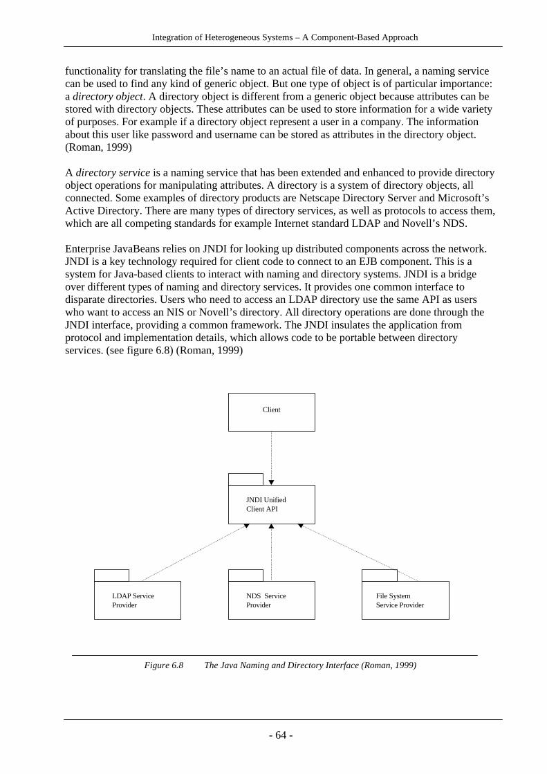
Integration of Heterogeneous Systems – A Component-Based Approach
- 64 -
functionality for translating the file’s name to an actual file of data. In general, a naming servicecan be used to find any kind of generic object. But one type of object is of particular importance:a directory object. A directory object is different from a generic object because attributes can bestored with directory objects. These attributes can be used to store information for a wide varietyof purposes. For example if a directory object represent a user in a company. The informationabout this user like password and username can be stored as attributes in the directory object.(Roman, 1999)
A directory service is a naming service that has been extended and enhanced to provide directoryobject operations for manipulating attributes. A directory is a system of directory objects, allconnected. Some examples of directory products are Netscape Directory Server and Microsoft’sActive Directory. There are many types of directory services, as well as protocols to access them,which are all competing standards for example Internet standard LDAP and Novell’s NDS.
Enterprise JavaBeans relies on JNDI for looking up distributed components across the network.JNDI is a key technology required for client code to connect to an EJB component. This is asystem for Java-based clients to interact with naming and directory systems. JNDI is a bridgeover different types of naming and directory services. It provides one common interface todisparate directories. Users who need to access an LDAP directory use the same API as userswho want to access an NIS or Novell’s directory. All directory operations are done through theJNDI interface, providing a common framework. The JNDI insulates the application fromprotocol and implementation details, which allows code to be portable between directoryservices. (see figure 6.8) (Roman, 1999)
Figure 6.8 The Java Naming and Directory Interface (Roman, 1999)
Client
JNDI Unified Client API
LDAP Service Provider
NDS Service Provider
File System Service Provider
Fig8. The Java Naming and Directory Interface (Roman, 1999)

Integration of Heterogeneous Systems – A Component-Based Approach
- 65 -
To use the services of a bean a client first obtains a reference to the bean's class Home Interfaceusing the Java Naming and Directory Interface (JNDI). Using this reference, the client softwarecan call a create method in the class's Home Interface, thus obtaining a reference to the bean'sRemote Interface implemented by the container. The Remote Interface then delegates subsequentmethod calls to the corresponding bean. The fact that the client uses JNDI, to obtain a referenceto the Home Interface of the class, is a necessary condition for distribution transparency. Anypiece of software, including a bean, may use the client contract to communicate with some bean,if the software does not know (or care) where the target bean is actually being deployed. Suchsoftware calls the interfaces in the container holding the target bean using Remote MethodInvocation. (Sousa & Garlan, 1999)
Figure 6.9 Detail of the Client Contract (Sousa & Garalan, 1999)
Other services in EJB
Enterprise Java Beans are named using the Java Naming and Directory (JNDI) API. The naminghierarchy has the EJB server at the top level, layered on the application name, then the containername. The bean is identified by a primary key within the container. There are no namingconvention requirements for the primary keys. In addition, CORBA Naming standard (COS) issupported. An EJB Server that supports COS will automatically publish a COS version of theEJB name. (Orchard, 1998)
The Container provides the life-cycle services of an object. All containers have a Home interfacethat provides Factory methods for creation of objects. Entity beans also have a set of Findermethods for retrieving objects based upon a primary key. Home interfaces have destroy methodsfor deleting objects.
EJB provides an infrastructure for distributed transactions using two-phase commit protocols. Itis based upon the OMG Transaction Service (OTS), specifically the Java Transaction
Client
HomeInterface
RemoteInterface
JNDI
ClientContract

Integration of Heterogeneous Systems – A Component-Based Approach
- 66 -
Service(JTS) implementation of OTS. JTS supports multiple transaction managers propagatingtransactions to multiple databases. One of the exciting aspects of EJB is that it brings the strengthof database transactions to objects. Distributed objects can participate in thebegin/prepare/commit sequence typical of transaction protocols. (Orchard, 1998)
The transaction requirements that a bean supports are specified in the transaction attributeassociated with the bean. The options are BEAN_MANAGED, NOT_SUPPORTED,SUPPORTS, REQUIRES, REQUIRES_NEW and MANDATORY. These options correspond tothe level of transaction support that a bean can operate in or that it requires from the container.Readers unfamiliar with transactions and two-phase commit protocols are encouraged toinvestigate transaction theory as it can significantly improve the robustness and integrity of dataand programs. (Orchard, 1998)
EJB can use CORBA and RMI for messaging. The beans are defined using the RMI interfaces,then the standard RMI deployment is used. EJB Servers can also support CORBA IIOPintegration. The EJB server provides a CORBA ORB and tools for creating a CORBA objectfrom the EJB object. It is also possible to support DCOM and COM this way.
The run-time information of the Bean is specified in a deployment descriptor field in an ejb-jarfile. The ejb-jar is installed in the EJB Server. It then deploys the bean according to thedescriptor fields, such as transaction characteristics. This is a natural extension of the packagingof the Java Beans specification.
To set up an EJB server
Setting up an Enterprise JavaBeans server requires six steps on the server:
1. Enterprise JavaBeans server vendors supply EJB components run on EJB containers. The firststep is therefore to download an EJB server. A server that is recommended by SUN is BEAWeblogic EJB server.
2. Construct a remote interface on the EJB server. The remote interface is the client’ s view ofthe EJB. The interface is developed using JAVA RMI syntax and the EJB container providergenerates the code for the interface.
3. Construct a home interface by which the container creates new session beans on behalf of theclient. Just like for the remote interface the home interface is declared using RMI syntax andimplemented by the container service provider tools.
4. Write an Enterprise JavaBean. Here is all the logic constructed.
5. The next step is to compile the three files above and package them into a so-called EnterpriseJavaBeans -jar file. This is the file the developer will place in the container.
6. Now, place the Enterprise JavaBeans-jar in the container. The way this is done depends onwhich server vendor that is used.

Integration of Heterogeneous Systems – A Component-Based Approach
- 67 -
After the server side is finished constructing containers and filling them with components theclient needs to find a specific EJB. The client accesses the Enterprise JavaBeans by looking upthe class that contains the EJB by name using Java Naming and Directory Interface (JNDI).JNDI is an API that provides naming and directory functionality for applications written in Java.The function the client programmer has to use is simply called lookup (“EJB_name”) whereEJB_name is the name of the Enterprise JavaBean.
The developers of Enterprise JavaBeans focus on making EJB work for business to businessintegration and their main approach is to make EJB work with different integration techniques.Lots of research is put into making EJB and CORBA work together where CORBA handles thetransaction and EJB the business logic. CORBA would then take the part that RMI has todaywith the biggest advantage that CORBA works with all programming languages. For someimplementations a co-operation between EJB and XML can be suitable. These two technologiesdo not have the same purpose but are complementary. Enterprise JavaBeans handles portablebusiness logic and XML technology defines a standard for portable data.
The Enterprise Java Beans specification provides a great first step in defining how Javadevelopers can build and re-use server logic. EJB is a natural extension of "Write Once, RunAnywhere" to middleware and protocols by providing a robust and well-defined framework fordevelopers and vendors. Developers will be able to focus more on business logic, and less onplumbing, while gaining independence from middleware. (Orchard, 1998)

Integration of Heterogeneous Systems – A Component-Based Approach
- 68 -
6.1.2 Component Object Model
Building applications from classes and their objects is relatively a new popular and modern method.One problem is that every programming language has its own notion of what an object is. There aremany programming languages (such as C++, Java, Delphi, and even Visual Basic) that supportobjects in some way, but the differences among them can cause confusion for developers. Thosedifferences also create difficulties for vendors that want to provide object services in a standard wayto their customers working in any language.
One way to solve this problem is to define a single object model that can be used across alllanguages. Once that object model exists, services that the operating system (or applications runningon that operating system) provides can all be exposed in a common way, regardless of the languagethey're written in. This is exactly what Microsoft's Component Object Model (COM) does.
COM is actually the foundation technology for Microsoft’s OLE and Active X. COM has its roots inOLE version 1, which was created in 1991 and was a proprietary document integration andmanagement framework for the Microsoft Office suite. Microsoft later realized that documentintegration is just a special case of component integration.
OLE version 2, released in 1995 was a major enhancement over its predecessor. The foundation ofOLE version 2, now called COM, provided a general-purpose mechanism for component integrationon Windows platforms. (North, 1997)
Microsoft Component Object Model (COM) refers to both a specification and implementationdeveloped by Microsoft Corporation, which provides a framework for integrating components.This framework supports interoperability and reusability of distributed objects by allowingdevelopers to build systems by assembling reusable components from different vendors, whichcommunicate via COM.
COM defines an application-programming interface (API) to allow for the creation of componentsfor use in integrating custom applications or to allow diverse components to interact. However, inorder to interact, components must adhere to a binary structure specified by Microsoft. As long ascomponents adhere to this binary structure, components written in different languages caninteroperate. (Microsoft, 1999)
COM can even be described as a language-independent, distributed, object-oriented system forcreating binary software components that can interact.
It is important to indicate that COM is not an object-oriented language but a standard. COM definesa language-independent notion of what an object is, how to create objects, how to invoke methods,and so on. This allows development of components that programmers can use (and reuse) in aconsistent way, of which languages they use to write the component and its client. COM does notspecify how an application should be structured. The language, structure and implementation detailsare left to programmer. COM specifies an object model and programming requirements that enableCOM objects (COM components) to interact with other objects. COM also defines how objects worktogether over a distributed environment and has added security features to ensure system andcomponent integrity. (Microsoft, 1999)

Integration of Heterogeneous Systems – A Component-Based Approach
- 69 -
It defines a binary structure for the interface between the client and the object. This binary structureprovides the basis for interoperability between software components written in arbitrary languages.As long as a compiler can reduce language structures down to this binary representation, theimplementation language for clients and COM objects does not matter. The point of contact is therun-time binary representation. Thus, COM objects and clients can be coded in any language thatsupports Microsoft's COM binary structure.
A COM object can support any number of interfaces. An interface provides a grouped collection ofrelated methods. COM objects and interfaces are specified using Microsoft Interface DefinitionLanguage (IDL), an extension of the DCE Interface Definition Language standard. (Gopalan, 1999)
Interfaces are considered logically immutable. Once an interface is defined, it should not be changed,new methods should not be added and existing methods should not be modified. Of course thisrestriction on the interfaces is not enforced, but it is a rule that component developers should follow.Adhering to this restriction removes the potential for version incompatibility. If an interface neverchanges, then clients depending on the interface can rely on a consistent set of services. If newfunctionality has to be added to a component, it can be exposed through a different interface.
Every COM object runs inside of a server. A single server can support multiple COM objects.There are three ways in which a client can access COM objects provided by a server:
1. In-process server: The client can link directly to a library containing the server.The client and server execute in the same process. Communication is accomplished throughfunction calls. (In this case the sharing of data between the two is simple).
2. Local Object Proxy: The client can access a server running in a different process but on thesame machine through an inter-process communication mechanism. This mechanism isactually a lightweight Remote Procedure Call (RPC).
3. Remote Object Proxy: The client can access a remote server running on another machine.The network communication between client and server is accomplished through DCE RPC.The mechanism supporting access to remote servers is called DCOM.
(When the server process is separate from the client process, as in a local server or remoteserver, COM must format and bundle the data in order to share it. This process of preparingthe data is called marshalling. Marshalling is accomplished through a "proxy" object and a"stub" object that handle the cross-process communication details for any particularinterface).
In the case 2 and 3, COM creates the "stub" in the object's server process and has the stub managethe real interface pointer. COM then creates the "proxy" in the client's process, and connects it to thestub. The proxy then supplies the interface pointer to the client. (Gopalan 1999)
The client calls the interfaces of the server through the proxy, which marshals the parameters andpasses them to the server stub. The stub “unmarshals” the parameters and makes the actual callinside the server object. When the call completes, the stub marshals return values and passes them tothe proxy, which in turn returns them to the client. The same proxy/stub mechanism is used when theclient and server are on different machines. However, the internal implementation of marshalling andunmarshalling differs depending on whether the client and server operate on the same machine(COM) or on different machines (DCOM). Given an IDL file, the Microsoft IDL compiler can create
Integration of Heterogeneous Systems – A Component-Based Approach
- 70 -
default proxy and stub code that performs all necessary marshalling and unmarshalling. (Gopalan1999)
All COM objects are registered with a component database. When a client wishes to create and use aCOM object:
1. It invokes the COM API to instantiate a new COM object.
2. COM locates the object implementation and initiates a server process for the object.
3. The server process creates the object, and returns an interface pointer at the object.
4. The client can then interact with the newly instantiated COM object through the interfacepointer.
An important aspect in COM is that objects have no identity. In other words, a client can ask for aCOM object of some type, but not for a particular object. Every time that COM is asked for a COMobject, a new instance is returned. The main advantage of this policy is that COM implementationscan pool COM objects and return these pooled objects to requesting clients. Whenever a client hasfinished using an object the instance is returned to the pool. However, there are even mechanisms tosimulate identity in COM but we will not talk about them here. (Gopalan, 1999)
COM has enjoyed great industrial support with thousands of developing COM components andapplications. COM even suffers from some weaknesses. The main problems with COM is:
1. COM is hard to use. Reference counting, Microsoft IDL, Global Unique Identifiers (GUID),etc. require deep knowledge of COM specification from developers.
2. COM is not robust enough for enterprise deployments. Services such as security,transactions, reliable communications, and load balancing are not integrated in COM.
But at all, a number of developers see COM as more than a little challenging to understand and use.The reason for this is simple: Using COM's language-independent objects in any real programminglanguage requires understanding a new object model, the one defined by COM. For example, a C++programmer knows that creating a new object requires using the language's new operator, whilegetting rid of that object requires calling delete. If that same C++ programmer wants to use a COMobject, however, she can't do things in this familiar way. Instead, she must call the standard COMfunction CoCreateInstance (or one of a few other choices) to create the object. When done with thisCOM object, she doesn't delete it explicitly, as in C++, but instead invokes the object's Releasemethod. The object relies on an internal reference count that it maintains to determine when it has nomore clients, and thus when it's safe to destroy itself. (Platt, 1999)
Writing COM objects requires a developer to provide a significant amount of infrastructure thatdoesn't vary much from one object to another. For example, every COM object requires animplementation of the Unknown interface, which provides reference counting and polymorphism.Many require a class factory to let the operating system reach into the server and create the object,and code for making the registry entries that tell the operating system where to find this class factory.Objects that want to run in scripting environments such as Web browsers (most objects, these days)need to implement a fairly complex interface called IDispatch to permit runtime binding to methodnames, and so on.
Integration of Heterogeneous Systems – A Component-Based Approach
- 71 -
An interesting thing about COM components is that they are never linked to any application. Theonly thing that an application may know about a COM object is what functions it may or may notsupport. In fact, the object model is so flexible that applications can query the COM object at run-time as to what functionality it provides. (Gopalan, 1999)
Garbage Collection is one other major advantage to using COM. When there are no outstandingreferences (a.k.a. pointers) to an object, the COM object destroys itself.
COM can even be seen relatively straightforward to use from some languages. Visual Basicprogrammers, for example, must make some COM-specific calls, but VB itself hides many of thedetails. Today, after the judgment, that Microsoft has got in fraction with SUN, we don’t knowclearly if Microsoft can yet have an implementation of the Java virtual machine or not but any way,Microsoft's implementation of the Java virtual machine makes COM's integration with Java evensimpler. It allows Java programmers to write ordinary Java code, and then silently performs anynecessary translations. But for C++ developers, using COM means understanding a significantnumber of COM-specific rules and API calls. While COM+ will bring some changes to developersworking in VB, Java, and other higher-level languages, it's C++ programmers who will mostappreciate it. Because COM+ relies on the C++ compiler to do much of the work of translatingbetween this language-independent object model and the C++ object model, the developer's lifebecomes easier. In COM, objects and their clients make calls on a standard COM library. Inlanguages like Visual Basic and Java, some or all of these calls are hidden, but C++ programmersuse this library directly.
The only language requirement for COM is that code is generated in a language that can createstructures of pointers and, either explicitly or implicitly, call functions through pointers.So Object-oriented languages such as MS Visual C++ and Smalltalk provide programmingmechanisms that simplify the implementation of COM objects but even some other languages suchas Ada, C, Java, Pascal and even Basic programming environments can create and use COM object.Many of the weaknesses in COM have disappeared in a new version of COM, which is calledCOM+. (Platt, 1999)
COM +
COM+ is much younger than COM. It came in 1997 with NT 5.0. NT 5.0 is named today asWindows 2000. COM+ combines enhancements to the Microsoft Component Object Model (COM)with a new version of the technology called Microsoft Transaction Server 2.0, along with many newservices. COM+ integrates MTS services and message queuing into COM, and makes COMprogramming easier through a closer integration with Microsoft languages, like Visual Basic, VisualC++, and J++. COM+ will not only add MTS-like quality of service into every COM+ object, but itwill hide some of the complexities in COM coding.
Actually, COM+ is many things. COM+ is the merging of the COM and MTS programming modelswith the addition of several new features.

Integration of Heterogeneous Systems – A Component-Based Approach
- 72 -
Some of these features are:
• Object Pooling
• Microsoft Message Queue (MSMQ)
• Role-based Security
• Queued Components
• Threading
• Automatic Transactions
• COM+ Events
• Application and Component Administration
COM was created long ago as a workstation-level component technology; with the release ofDistributed COM (DCOM) in Windows NT 4.0, the technology was expanded to support distributedapplications via remote component instantiation and method invocations. MTS followed. It wasdesigned to provide server-side component services and to fix some of DCOM’s deficiencies, e.g.,how it handles security issues, and the complete lack of a component management and configurationenvironment. COM+ now comes along to unify COM, DCOM, and MTS into a coherent, enterprise-worthy component technology. (Platt, 1999)
Note that programs running on NT or Windows 95 operating systems can be clients of COM+objects running on Windows 2000, but cannot be servers. In one sense, COM+ is just the Windows2000 release of COM, with incrementally more new features to solve new problems, the same asprevious releases of COM have had.
COM+ takes the COM and MTS programming models to the next level. At the same time, COM+addresses many of the shortcomings associated with COM and DCOM development, for example,COM+ provides a much better component administration environment, support for load balancingand object pooling, and an easier-to-use event model.
Here’s another way to look at COM+: It is the maturation of Microsoft’s component architecture.COM has always been difficult for developers to understand, at least initially. Developing COM-based applications requires a change in mindset. It’s almost as difficult as moving from C to C++programming. COM+ doesn’t necessarily change this completely, but it does move many of thedetails into the operating system so developers are free to focus on higher-level problems and theirsolutions. (Platt 1999)
Today, COM and MTS components place all of their configuration information in the Windowsregistry. With COM+, however, most component information will be stored in a new database,currently called the COM+ Catalog. The COM+ Catalog unifies the COM and MTS registrationmodels and provides an administrative environment for components. As a developer you interactwith the COM+ Catalog using either the COM+ Explorer or through a series of new COM interfacesthat expose its capabilities.
Integration of Heterogeneous Systems – A Component-Based Approach
- 73 -
One COM+ feature is its support for declarative programming. What this means is that you candevelop components in a generic way and defer many of the details until deployment time.COM+ is a good candidate to implement the middle layer of multi-tier architectures. The distributionsupport and quality of service provided by COM+ can help to overcome some of the complexitiesinvolved in these architectures.
COM+ Programming is based on the following points:
1. COM+ Programming is Interface Programming. This means that clients program on the basisof Interfaces not Classes.
2. Code is not statically linked but is loaded at runtime as and when required.
3. Component implementers specify their requirements declaratively and the framework ensuresthat these requirements are met as in an MTS or a COM+ system.
COM+ still provides a standard library, and objects and their clients still use it. But in contrast toCOM, COM+ hides calls to this library beneath the equivalent native functions in the programminglanguage.
Since COM+ is involved in every method call, it's now possible to insert other objects in that path. ACOM+ object that is automatically invoked during access of another COM+ object is called aninterceptor. One or more interceptors can lie in wait along the path. For example, an interceptormight perform a security check on the client, then cause the method call to fail if the necessarypermissions aren't in place.
In COM, the COM library is not directly involved when a client calls a method in a COM object.Instead, the call goes directly from the client to the object. In COM+, this is no longer true. AllCOM+ method calls pass through the COM+ library, although Microsoft promises that the overheadthis incurs will be negligible. For example, C++ programmers can use the standard new operatorrather than CoCreateInstance to create a COM+ object. In doing so, they are relying on a C++compiler that is aware of COM+ to generate the correct code to call the COM+ library.
To accomplish this, the compiler uses the COM+ library at compile time, then embeds calls to thissame COM+ library in the generated binary. Microsoft will provide this library, and any languagetool that wants to use COM+ must rely upon it. Unlike classic COM, where only COM objects andtheir clients use the COM library, COM+ also requires compilers (or interpreters, such as those forVisual Basic, and scripting languages, like JavaScript) to rely on a standard library to produce thecorrect code. Microsoft's competitors in the tools market, already accustomed to working on top oftheir competitor's operating system, now face the prospect of depending on yet another Microsoft-supplied component for key functions. The benefit, however, is that doing this will make usingMicrosoft's language-independent object model easier for their customers, too.
Object Pooling
Object pooling allows an application to create objects that can be created and pooled according toapplication needs. Reusing the elements in a pool of deactivated objects can save on system
Integration of Heterogeneous Systems – A Component-Based Approach
- 74 -
resources. You can pool almost any kind of object, and object pooling is easy to implement.(Microsoft, 1999)
Microsoft Message Queue (MSMQ)
MSMQ is a middleware product that enables asynchronous communications between applications.This means that client applications can send messages to a server even when the server isn't running.It also means that the server can receive messages after the client application has gone away. Inenvironments in which client applications and servers can become disconnected for any number ofreasons, this capability allows the distributed application as a whole to stay up and running. MSMQis based on the asynchronous delivery of messages to named queues. It's a product that can beintegrated into distributed applications, including those based on MTS. Messages model procedurecalls between a client and a server except that either party can do its work in the absence of the other.(Microsoft, 1999)
For example, in a sales order application a client could submit several orders to the queue even whenthe server application wasn't running. At some time later when the server was started, the servercould open the queue and retrieve all the order requests that were submitted by any client. MSMQalso makes it possible to return a message receipt to the caller as if it were the response to a methodcall. MSMQ also contributes to an application's scalability. As the traffic in a distributed applicationincreases, the managers of the system need to add more computers to increase the throughput of theentire system. To make use of any additional hardware, the system must somehow distribute clientrequests across all the available servers. This act of using as many of the available processing cyclesas possible is known as load balancing. A queue facilitates load balancing because a client doesn'tsend a request to a specific server. The queue is a single repository that holds all incoming requests.A group of servers monitors the queue and splits up the workload as it arrives. Visual Basicprogrammers can access MSMQ services through a set of COM interfaces. MSMQ integration withMTS makes it possible for a business object to retrieve a message from a queue inside a declarativetransaction. If something goes wrong during the transaction, the message is left in the queue. Thismeans that MSMQ can ensure that all messages eventually reach their destination. MSMQ alsoprovides advanced features that address routing efficiency, security, and priority-based messaging.(Microsoft, 1999)
Role-based Security
COM+ supports both role-based security and process access permissions security. In the role-basedsecurity model, access to parts of an application are granted or denied based on the logical group orrole to which the caller has been assigned (examples of roles could include administrator, developer,and other actors). Also in role-based security is the ability to have security at the method level, aswell as at the component and interface levels. (Platt, 1997)
Integration of Heterogeneous Systems – A Component-Based Approach
- 75 -
Queued Components
Queued Components allow you to create components that can execute immediately if the client andserver are connected; or, if the client and server are not connected, the components can deferexecution until a connection is made. Queued Components is key functionality for line-of-businessapplications built for enterprises. It augments "real time" transactions with the infrastructurenecessary to process asynchronous, queued transactions. This technology is effective for creatingapplications used by clients "in the field" and disconnected from a network; the client can entertransactions that will be executed when the client is again connected to the network. Thisasynchronous message queuing uses Windows 2000 Messaging Services. (Platt, 1999)
Threading
COM+ includes a new threading model called the neutral threading. The neutral model supportsexecution of objects on any thread type. The benefit of neutral apartment threading is that it does notrequire the developer of objects running in a neutral apartment to make the object thread safe.(Microsoft, 1999)
Automatic Transactions
COM+ supports all Microsoft Transaction Server (MTS) 2.0 semantics and adds "Auto-done," whichallows the system to automatically call SetAbort if an exception is triggered or SetComplete if not. Inaddition, COM+ supports components with a special environment called a context, which providesan extensible set of properties that define the execution environment for the component. (Microsoft,1999)
COM+ Events
COM+ event is a component-based event system using publishers and subscribers. Publishers sendevents to subscribers; the publisher through subscriptions identifies subscribers. Publishers can beany COM+ objects that call an event object, and subscribers can be simple COM+ objects thatimplement the methods on the event interface. (Microsoft, 1999)
Application and Component Administration
In COM+, a new registration database called RegDB stores the metadata that describes components.This database is highly optimized for the type of information that COM+ needs for activation ofcomponents and is used instead of the system registry. In addition, COM+ exposes a transactional,scriptable interface called the COM+ catalog, which accesses information in the RegDB. Finally, theComponent Services administrative tool provides a fully scriptable user interface for both developers

Integration of Heterogeneous Systems – A Component-Based Approach
- 76 -
and administrators to administer components as well as deploy both client-side and server-side multi-tier applications.
Metadata's Importance
Today, a COM object defines the methods it supports in some number of interfaces, each of whichcan be described using COM's interface definition language (IDL). A tool (the MIDL compiler) thencompiles an object's IDL to produce a type library, commonly stored in its own file. Clients of theobject can (but don't have to) read this library to learn how to make calls on the object's methods.In COM+, developers no longer need to define interfaces using IDL. Instead, they can just use theirprogramming language's syntax to define the object's interfaces. The compiler for that language thenworks with the COM+ library to generate metadata for the object. Metadata, essentially a superset ofthe information in today's type library, goes in the object's same binary file. And unlike optional typelibraries, every COM+ object must have metadata.
Even more interesting, COM+ object metadata will be accessible through the generic data accessinterfaces defined by OLE Database (more commonly called OLE DB). These let clients of theobject issue SQL queries against its own metadata, in order to search for methods or parameter types.One obvious problem: Not relying on the current IDL might mean adding syntax extensions toprogramming languages to accomplish the same function. Microsoft can use whatever interfacedefinition syntax it chooses for Visual Basic, since it owns the language. Java already has standardlanguage constructs for specifying interfaces. But C++, which will benefit most from COM+,currently has no standard way to specify interfaces. Although plans are not yet finalized, Microsoftsays it intends to extend the language syntax by implementing an interface definition scheme in itswidely used Visual C++ compiler.
Since every COM+ object has metadata, it's also possible to approach marshaling consistently.Marshaling is packaging a method call's parameters in some standard way, allowing these parametersto move effectively between objects written in entirely different languages or running on entirelydifferent machines. COM today provides two very different solutions to perform marshaling.(Gopalan, 1999)
If an object exposes its methods using a vtable interface (also called a custom interface), its clienttypically relies on a proxy and stub to marshal and unmarshal the parameters for calls to thosemethods. A stub and proxy can be automatically generated from an interface's IDL definition usingthe same MIDL compiler that produces type libraries.
The other way is for a COM object to expose its methods using a dispatch interface (ordispinterface). In this case, a client need not rely on a proxy and stub for marshaling andunmarshaling. Instead, the client can read an object's type library, and then dynamically performmarshaling as required. This is a more flexible system; however, since not all COM objects havetype libraries, it's not always possible in practice today.
But every COM+ object has metadata, the new equivalent of a COM type library. So COM+ canpotentially get rid of proxies and stubs altogether, allowing a single consistent type of marshaling.COM+ also does away with the distinction between vtable interfaces and dispinterfaces, aninconvenient artifact of the way COM grew. While Microsoft has indicated that the first release of

Integration of Heterogeneous Systems – A Component-Based Approach
- 77 -
COM+ might still need proxies and stubs, the intent is clearly toward dynamic marshaling as thestandard approach.
COM+ addresses yet another important but challenging problem in creating a language-independentobject model: data types. Different languages support different data types, which causes problemswhen passing parameters between objects written in different languages. C++, for example, supportsstructures, while Visual Basic does not. Today, COM supports one set of data types for vtableinterfaces (defined with C++ in mind) and yet another more limited set of data types for dispinterfaces (created with Visual Basic in mind). COM+ gets rid of this historical distinction by definingone common set of data types that are usable across all interfaces and then relying on the COM+library to perform any translations that are necessary.
COM+ brings many other changes to the COM. One of the most important: COM+ eliminates theneed for clients to call Release when they are done using an object. Instead, the COM+ libraryautomatically handles reference counting, always one of COM's most error-prone areas. And whileCOM has always supported interface inheritance, COM+ also allows implementation inheritancebetween COM+ objects running in the same process. Despite years of arguing that this was not adesirable feature for a component model, Microsoft appears to have yielded to the demands of atleast some of their customers and added this feature. (Gopalan, 1999)
COM+ also changes COM's persistence model. Today, the creator of a COM object must typicallyimplement one or more of a fairly large set of interfaces related to persistence. A client of this objectthen calls various methods in those interfaces to have the object load or save its persistent state. Butthe COM+ library provides standard support for persistence, removing much of the burden from theCOM+ object implementor. And by representing an object's properties in a standard way("serialization"), COM+ lets you pass objects by value. All that's required is to send this serializedrepresentation of an object's data to another object of the same class.
Another interesting change from COM to COM+ is that support for constructors, makes COM+objects more like objects in a typical object-oriented programming language. Languages like C++and Java can define a constructor method that runs when first creating an object. The creator of theobject can then pass parameters as needed to this constructor, allowing easy initialization. So COMobjects do not support constructors, but COM+ objects do. COM+ constructors even allow passingparameters, better integrating COM+ objects and the objects used by today's most popular object-oriented languages.
DCOM
The Distributed Component Object Model (DCOM) is a protocol that enables software componentsto communicate directly over a network in a reliable, secure, and efficient manner. Previously called"Network OLE," DCOM is designed for use across multiple network transports, including Internetprotocols such as HTTP.
Distributed COM is an extension to COM that allows network-based component interaction. WhileCOM processes can run on the same machine but in different address spaces, the DCOM extensionallows processes to be spread across a network. With DCOM, components operating on a variety ofplatforms can interact, as long as DCOM is available within the environment. (Microsoft, 1999)

Integration of Heterogeneous Systems – A Component-Based Approach
- 78 -
Microsoft Transaction Server (MTS)
A transaction defines a set of events that are guaranteed to be committed or rolled back as a unit.Accordingly, every transaction has a beginning, some number of events that are part of thetransaction (such as database updates), and an end. Exactly how a transaction's boundaries aredemarcated can vary. A common approach in traditional client/server transaction products is torequire the client to make a specific call to the transaction coordinator to begin the transaction. Theclient then makes calls to the components that carry out this transaction's work, and finally ends thetransaction with another explicit call to the transaction coordinator. This final, transaction-endingcall can indicate that the transaction should be committed, making all of its changes permanent, oraborted, causing all of its changes to be rolled back. It's the job of the transaction processing systemto ensure that exactly one of these two outcomes occurs. (Microsoft, 1999)
Microsoft Transaction Server is a component-based transaction processing system/service fordeveloping, deploying, and managing high-performing, scalable, and robust enterprise,Internet, and intranet server applications. MTS was first available in 1996 in the Windows NToperating system (such a separate packet). (Platt, 1999)
MTS is a component runtime environment, in which components live, which watches requestscoming into components and participates in processing them, providing security, automatictransaction management and a scaleable environment. Also, it is important to realize that MTS is astateless component model, whose components are always packaged as an in-proc DLL. Since theyare composed of COM objects, MTS components can be implemented in a variety of differentlanguages including C++, Java, Object Pascal (Delphi), Visual Basic and even COBOL!
MTS is actually built on COM and brings in mainframe-like transactional reliability to the PC worldfollowing a "write once, run many" strategy. Developers use MTS to deploy scalable serverapplications built from COM components, focusing on solving business problems instead of on theprogramming application infrastructure. MTS delivers the "plumbing" - including transactions,scalability services, database connection management, and point-and-click administration - providingdevelopers with the easiest way to build and deploy scalable server applications for business and theInternet. (Gopalan, 1999)

Integration of Heterogeneous Systems – A Component-Based Approach
- 79 -
Figure 6.10 Microsoft Transaction Server Model (Microsoft, 1999)
An MTS architecture is mainly built of 5 things:
1. The MTS executive (mtxex.dll)
2. A factory wrapper and a context wrapper for each component
3. The MTS server component
4. MTS client
5. And some other additional services systems such as Service Control Management, COMruntime services, the COM Transaction Integrator etc.
An MTS application is implemented as one or more components. Those COM-Components that arerunning under MTS are called MTS Component. The MTS Executive manages these components.MTS relies on a class factory object to create specific instances of each COM class.
When a client send a call to MTS component, the Factory Wrapper and the Object Wrapper catchthis call and inject their own algorithm, called JITA1, into the call and send in to actual MTScomponent. (Microsoft, 1999)
1 Just In Time Activation

Integration of Heterogeneous Systems – A Component-Based Approach
- 80 -
Figure 6.11 A basic MTS architecture (Gopalan, 1999)
To allow MTS to provide extra services, the MTS Executive transparently inserts a wrapper objectbetween each object it manages and that object's client. For example, when a client uses the COMIClassFactory interface to create an instance of a MTS object, that call is actually made on a factorywrapper object implemented by MTS, which in turn passes on the call to the real class factory.Similarly, every method call a client makes on the business methods of a MTS object is first handledby a MTS-supplied context wrapper object. The MTS Executive also supplies a context object foreach MTS object. This context object maintains information specific to the MTS object, such as whattransaction it belongs to (if any) and whether it has completed its work. Every context objectimplements the IObjectContext interface, through which an MTS object, can access the services thatMTS provides.
MTS objects are typically designed to encapsulate some set of business functionality. For example,an MTS object might allow a client to transfer money between two accounts or build and submit anorder of some kind. Because MTS objects are written as distinct components, business functionsencapsulated into these objects can be combined in arbitrary ways, allowing them to be flexiblyreused. Although it's not strictly required, an MTS object is typically accessed by one client at atime, and it may (but isn't required to) use transactions.
An MTS client needs to do nothing special to create and work with transactional objects; to a client,an MTS object looks like an ordinary COM object. (Microsoft, 1999)
mtx.exe
InterfaceMyComponent
MyServer.dllmtxex.dll
FactoryWrapper
ObjectWrapper
ContextObject
Client
InterfaceClassFactory
InterfaceClassFactory
Database
MTS ServerObject
(Class Factory Object)
MyComponentImplementation
(MTS Object)
InterfaceMyComponent
InterfaceObjectContext
MTS ComponentMTS Executive
Integration of Heterogeneous Systems – A Component-Based Approach
- 81 -
Transactions in Microsoft Transaction Server
When combining transactions with components, the traditional client-controlled model isn't usuallythe best approach. Instead, MTS introduced a new way to demarcate transaction boundaries. Calledautomatic transactions, it allows clients to remain unaware of when transactions begin and end—theynever need to make explicit calls to begin or end a transaction. Instead, when a transaction beginsdepends on the value of that component's transaction attribute. This value can be set to one of fourpossibilities
• If a component is marked as Requires New, the MTS Executive will always begin atransaction when its caller first invokes a method in one of that component's objects.
• If a component is marked as Required, the MTS Executive will begin a transaction when itscaller first invokes a method in one of that component's objects unless the caller is alreadypart of a transaction. In this case, any methods invoked in the object will become part of theexisting transaction.
• If a component is marked as Supported, the MTS Executive will never begin a transactionwhen a caller invokes methods in one of the component's objects. If the caller is already partof a transaction, the work this object does will become part of that transaction. If the caller isnot part of a transaction, this object's work will execute without being wrapped inside atransaction.
• If a component is marked as Not Supported, the MTS Executive will never begin atransaction when a caller invokes methods in one of the component's objects. Even if thecaller is part of an existing transaction, this object's work will not become part of thattransaction.
When it has finished its work, an MTS object can call either SetComplete, if it wishes to commit thatwork, or SetAbort, if the work it has done should be rolled back. If neither is called by the time thisobject's transaction ends, the MTS Executive behaves as though the object called SetComplete-thedefault behavior is to commit the transaction. These calls are made by a method in the MTS objectitself, not by the client (again, the client need not be aware that transactions are being used). If everyobject participating in the transaction agrees to commit, the MTS Executive will tell the transactioncoordinator to commit the transaction. If any MTS object in this transaction calls SetAbort, however,the MTS Executive will tell the transaction coordinator to abort the transaction. (Gopalan, 1999)

Integration of Heterogeneous Systems – A Component-Based Approach
- 82 -
6.1.3 CORBA (Common Object Request Broker Architecture)
CORBA is a specification developed by the Object Management Group (OMG) to aid indistributed objects programming.
Object Management Group (OMG)
The Object Management Group is an international non-profit organization that is supported byover 800 members, including IS vendors, software developers and users. Its purpose is toestablish industry guidelines and specifications for object management to provide a commonframework for application development. This framework is intended to make it possible todevelop heterogeneous applications environments across all major hardware platforms andoperating systems. OMG produces specifications only, not executable systems. OMG alsopromotes using object-oriented technology in software development and has established theObject Management Architecture (OMA), which provides the conceptual infrastructure uponwhich all OMG specifications are based. (Object Management Group, 2001)
OMA Object Model and Reference Model
The Object Management Architecture Guide defines an abstract Core Object Model. From thismodel, a concrete Object Model that underlies the CORBA architecture is derived. The concreteObject Model provides a presentation of object concepts and terminology. (Object ManagementGroup, 2001)
In the OMA Object model, an object is an identifiable, encapsulated entity that provides one ormore services that can be requested by a client. Clients issue requests to objects to performservices on their behalf. The implementation and location of each object are hidden from theclient making the request. A client makes the request through the object’s interface, which is adescription of a set of operations. A client object is an object, which issues a request for aservice. A server object is an object providing response to a request for a service. This meansthat a given object may be a client for some requests and a server for other requests. (ObjectManagement Group, 1997)
The Object Management Architecture Guide also defines a Reference Model (see figure 6.12).The Reference Model identifies the components, interfaces and protocols that compose theOMA, where CORBA is one of these components. The Reference Model consists of thefollowing components:

Integration of Heterogeneous Systems – A Component-Based Approach
- 83 -
Figure 6.12 OMG Reference Model: Interface Categories (Object Management Group, 1997)
Object Request Broker (CORBA)
The Object Request Broker is the central item in the OMA. It is this component that iscommercially referred to as CORBA. The ORB is the middleware that manages the client-serverrelationships between objects. “The term middleware is used to describe separate products thatserve as the glue between two applications. Middleware is sometimes called plumbing because itconnects two sides of an application and passes data between them.” (The Lycos Tech Glossary,2001) It provides an infrastructure that allows objects to communicate, independent of thespecific platforms and techniques that are used to implement the objects. By using an ObjectRequest Broker, a client can transparently invoke an operation on a server object, which can beon the same machine or across the network; the client will not notice any difference. The ORB isresponsible for finding the object implementation for a request, to pass the parameters, invokethe operation and return the results. It is like a telephone exchange, providing the basicmechanism for making and receiving calls. The client does not have to be aware of the object’slocation, its programming language, its operating system, or other system aspects that are notpart of the object’s interface. (Object Management Group, 1997)
Object Services (CORBA Services)
The Object Services component provides general, domain-independent services that are likely tobe used in any program that is based on distributed objects. There are so far 16 standardizedservices that handle tasks such as naming of objects, object security, creation and deletion of

Integration of Heterogeneous Systems – A Component-Based Approach
- 84 -
objects, locating objects by attributes, etc. Note that since OMA is a specification and not anexecutable system, OMA only provides the interface definitions for these services. However,there are implementations of these services in the market, which can be bought off-the-shelf andused directly with a CORBA application. The table below gives a short explanation of eachservice. (Object Management Group, 1997; Szyperski, 1999)
Name DescriptionCollectionService
Provides a uniform way to create and manipulate collections,like stacks, queues and lists.
ConcurrencyService
Enables multiple clients to coordinate their access to sharedresources.
Event Service Allows definition of event objects that can be sent from eventsuppliers to event consumers.
ExternalizationService
Provides support for externalizing and internalizing objects(recording object state to a stream of data and vice versa).
LicensingService
Provides a mechanism to control how an application is used,for example by setting start and expiration dates.
LifecycleService
Supports creation, copying, moving, and deletion of objectsand related groups of objects.
Naming Service Allows association of object references with symbolic names,and lets clients find objects based on these names.
NotificationService
Provides an extension of the Event Service, with some newcapabilities.
PersistentObject Service
Provides interfaces to the mechanisms used for managingpersistent storage of objects.
PropertyService
Allows arbitrary properties to be associated with objects.
Query Service Allows clients to invoke queries on collections of objects.RelationshipService
Allows general relations between objects to be specified andmaintained.
SecurityService
Provides identification and authentication of users to verifythey are who they claim to be, authorization and accesscontrol, etc.
Time Service Handles inaccuracies in a distributed system with multipleasynchronous clocks.
Trader Service Allows clients to find objects based on their properties,describing the service offered by the object.
TransactionService
Supports multiple transaction models.
Common Facilities (CORBA Facilities)
The Common Facilities component provides services that many applications may share, butwhich are not as fundamental as the Object Services. These interfaces are oriented towards end-user applications. There are four areas for standardization so far, though most of thestandardization within these areas is not yet finalized and implemented. The areas are user

Integration of Heterogeneous Systems – A Component-Based Approach
- 85 -
interfaces (for example printing, email, object linking), information management (structuredstorage, universal data transfer, meta-data), system management (instrumentation, monitoring,logging) and task management (workflow, rules, agents). (Object Management Group, 1997;Szyperski, 1999)
At present, the only current formal specifications that have been adopted are theInternationalization and Time specification, which defines a set of interfaces for extractinginformation from localized representation of dates, times and numbers, and the Mobile AgentFacility specification, which provides a standardization of agent management and transfer toachieve a higher interoperability between various agent systems. (Object Management Group,2000a, January; Object Management Group, 2000b, January)
Domain Interfaces (CORBA Domains)
These are domain-specific interfaces for application domains such as Finance, Healthcare,Manufacturing, Telecom, Electronic Commerce, and Transportation. OMG has a large numberof special interest groups, which focus on different application domains. (Object ManagementGroup, 1997)
Application Objects (CORBA Applications)
These are interfaces developed specifically for a given application domain. Basically, anyapplication that anyone writes that uses CORBA counts as a CORBA Application. Because theyare application-specific, these interfaces are not standardized, except for a few more broadlyuseful application objects, like Business Objects. Business Objects are application objects thatdirectly make sense to people in a specific business domain, like customer or stock objects.(Szyperski, 1999; Vinoski, 1997)
Object Request Broker (ORB)The Object Request Broker that was shortly described above, consists of the following primarycomponents: the ORB Core, an ORB Interface, OMG IDL stubs and skeletons, DII, DSI, andObject Adapters. Clients use the ORB to make requests to objects. Figure 6.13 shows thestructure of an ORB.

Integration of Heterogeneous Systems – A Component-Based Approach
- 86 -
Figure 6.13 Structure of an individual Object Request Broker (Object Management Group, 2001)
Object implementation (Servant)
A CORBA object is an instance of an implementation and an interface. It is identified, located,and addressed by its object reference. An object encapsulates state and operations (that areinternally implemented as data and methods) and is capable of being located by an ObjectRequest Broker and having client requests delivered to it. When a client invokes an operation onan object, the object implementation acts as a server for the request. An object and itsimplementation is not part of the ORB, but it uses the ORB to receive requests from clients andto send responses. (Object Management Group, 2001)
Another name for the object implementation is servant. The servant consists of animplementation programming language entity that defines the operations that are supported bythe object’s interface. Servants can be written in many different programming languages. (ObjectManagement Group, 2001)
Client
A client is the program entity that invokes operations on an object. The client only knows theobject through an interface and knows nothing about its implementation. The term client issomething that is relative to a particular object. This means that an implementation of one object
Integration of Heterogeneous Systems – A Component-Based Approach
- 87 -
may be a client of other objects. The client is not part of the ORB, but it uses the ORB to makerequests to objects. (Object Management Group, 2001)
There are three different ways for a client to obtain a reference to a remote object:
• To create a new object, by invoking a creation request, which will return an object referenceto the newly created object.
• To invoke a lookup service, like the Naming Service, that allows the client to obtain anobject reference by giving the name of the object, or the Trader Service, that allows the clientto obtain an object reference by giving the properties of the object.
• By converting a string into an object reference. Objects can be turned to strings and storedinto a file or a database, and later be retrieved and turned into an object reference again.(Vinoski, 1997)
Object Request Broker Core (ORB Core)
The ORB Core is the part of the ORB that provides the basic representation of objects and thecommunication of requests. It supports the minimum functionality to move a request from aclient to the appropriate adapter for the target object, and return any response to the client. TheORB hides from the client the object location, the object implementation, whether the object isactivated or not when the request arrives and what communication mechanism the ORB uses tosend the request. (Object Management Group, 2001; Vinoski, 1997)
ORB Interface
The ORB Interface is an interface to the operations that are implemented by the ORB Core. Thepurpose of the ORB interface is to decouple applications from ORB implementation details. Theoperations are available to both clients and server objects. These operations do not depend onany specific object adapter (this term is described later), and are the same for all ORBs and allobject implementations. Some examples of the operations that the ORB Interface provide are:§ object_to_string()/string_to_object(): Converts an object reference to a string and vice
versa. A stringified object reference can be written down as text somewhere and later betransformed back to a valid object reference.
§ resolve_initial_references(): Helps the client find the object references needed to getstarted, might for example be used to find the object reference to the Naming Service.
§ BOA_init(): Initializes an object adapter. (Benjamin, Vasudevan, Villalba & Vogel, 1999;Object Management Group, 2001)
OMG IDL stubs and skeletons
The OMG Interface Definition Language is an object-oriented declarative language, that is usedto define the objects’ interfaces. It is not a complete programming language; it is only used for

Integration of Heterogeneous Systems – A Component-Based Approach
- 88 -
describing interfaces, and does not contain any executable statements (like for-loops or if/else-statements). Interfaces declared in IDL are programming language neutral. The interfaces consistof attributes and a set of named operations with the parameters to those operations. ThroughIDL, an object tells its potential clients what operations are available and how they should beinvoked. From these IDL definitions the CORBA objects are mapped to the objectimplementations, written in different programming languages. (Mahmoud, 2001)
Programming languages with IDL mapping are for example C, C++, Java, Smalltalk andCOBOL. This separation of object definition and implementation makes it possible to use anyprogramming language with an IDL mapping to make remote requests to a CORBA object.Although OMG IDL is an object-oriented language, it is possible to use programming languagesas C and COBOL with CORBA, as long as there is an IDL mapping for these languages. In thesenon-object oriented languages an object will be mapped to a collection of functions thatmanipulate data (e.g. an instance of a struct or record) that represent the state of the CORBAobject. (Benjamin et al., 1999)
OMG IDL language compilers generate client-side stubs and server-side skeletons in a specificprogramming language. The stubs and skeletons are built directly into the client application andobject application. The client makes local invocations to the stub, which transforms these toremote invocations, by marshalling them and forwarding them through the ORB to the target object. Marshalling means to convert therequest from its representation in a programming language to one that is suitable for transmissionover the connection to the target object. The skeleton receives invocations, unmarshals them(converting from a transmittable form to a programming language form) and invokes the targetmethod. It also accepts return values, marshals these and sends them back to the client. (ObjectManagement Group, 2001; Szyperski, 1999)
There are two ways for an object implementation to be connected to the skeleton. The first is toderive the implementation from the skeleton, which is usually done by inheritance. This means thatthe implementation extends the skeleton. The other way is the delegating approach, which meansthat the skeleton delegates the execution to the implementation, which is kept separate from theskeleton. This second approach is useful when integrating legacy code, since the legacy code will nothave to be changed to inherit from the skeleton. (Appelbaum et al., 1999; Schmidt & Vinoski, 1997)
A simple IDL interface definition might look like:
interface Meeting{attribute string date;void scheduleMeeting();};
This interface defines a string attribute named “date”. String is a CORBA data type that the IDLcompiler must map to an equivalent language-specific type. An attribute keyword corresponds to twooperations that the implementation must provide: an operation for retrieving the item and one formodifying it. These operations are sometimes called “getters” and “setters”. The interface in theexample also defines an object that has an operation named scheduleMeeting(), which takes noparameters and returns nothing.

Integration of Heterogeneous Systems – A Component-Based Approach
- 89 -
IDL interfaces are allowed to inherit from each other, which makes it possible to reuse existinginterfaces when defining new services. Multiple inheritance is also allowed. All interfacesimplicitly inherit from CORBA::Object. The CORBA::Object interface defines some operationsthat are applicable to any object. These operations are implemented by the ORB.CORBA::Object provides operations to retrieve interface type information for the objectreference, to duplicate and release object references, to create request objects for the DII, etc.(Benjamin et al., 1999)
If running the example file in an IDL compiler with Java mapping, the compiler will create astub file, a skeleton file, some extra help files and a file that defines the remote interface as aJava interface. This last file will look like:
public interface Meetingextends org.omg.CORBA.Object{
String date();void date(String arg);void scheduleMeeting();
}
Now, the implementation of the interface can be written. Some IDL compilers alsogenerate part of the implementation class, so the programmer just can “fill in” the rest.
Dynamic Invocation Interface (DII)
The Dynamic Invocation Interface describes the client’s side of the interface that allows dynamiccreation and invocation of requests to objects. Dynamic creation and invocation means that theclient does not need to know the type of object it will create/invoke at compilation time in theform of static stubs. (Object Management Group, 2001)
Using DII is more tedious than coding static stubs. When using IDL, the client stub that isgenerated by the IDL compiler hides the complexity of the low-level communication betweenthe client and server. When a client makes a request to a server object, the client stub performssome steps behind the scenes. When using DII, the programmer must self locate the serverobject, determine the object’s interface by using the Interface Repository (described later), builda request, invoke the request and retrieve the returned values. Some applications, like objectbrowsers or monitors that need to access any object without previous knowledge of theirinterfaces, are suitable for using DII directly. An advantage of using DII is that it supports easilyreplacing server objects without affecting the client. (Appelbaum, Claudio, Cline, Girou &Watson, 1999)
Dynamic Skeleton Interface (DSI)
The Dynamic Skeleton Interface (DSI) allows for dynamic handling of object invocations, and isthe server side’s analogue to the client side’s DII. The DSI is a way to deliver requests from anObject Request Broker to an object implementation that does not have compile-time knowledge

Integration of Heterogeneous Systems – A Component-Based Approach
- 90 -
of the type of the object it is implementing. The client that makes the request does not knowwhether the implementation is using the IDL skeletons or is using the dynamic skeletons. (ObjectManagement Group, 2001)
Using DSI means that the object implementation is responsible for determining the operationbeing requested, interpreting the arguments associated with the request and invoking theappropriate internal operation to fulfill the request and returning the appropriate values. Toimplement an object with DSI requires, as for DII, more manual programming activity than whatis required when using static skeletons. DSI can for example be useful when an object needs tooffer multiple interfaces. (Appelbaum et al., 1999)
Object Adapters (OA)
An Object Adapter serves as the “glue” between object implementations/skeletons and the ORB.The object adapter adapts the interface of the object implementation to the interface expected bythe ORB. Without object adapters, the object implementations would connect themselvesdirectly to the ORB to receive requests. This would mean that the ORB would be forced tohandle a large range of different interfaces to different styles of object implementations, whichwould make the ORB unnecessary complex. The object adapter assists the ORB with registeringprogramming language entities as object implementations, generating object references,activating objects, invoking methods, etc. (Object Management Group, 2001; Vinoski, 1997)
For example, when a client invokes an operation on an object, the object adapter will map theobject reference to the corresponding object implementation. If a client tries to invoke anoperation on an object that is not in memory, the object adapter activates the object (initializes itinto memory) so it can perform the requested operation. The object adapter can also deactivateobjects. This means that all objects do not have to reside in memory all the time, but it willappear as if they were, to the client. There may be different adapters provided for different kindsof implementations. A different object adapter is normally necessary for each differentprogramming language. (Object Management Group, 2001; Vinoski, 1997)
Other components
• Interface Repository: A service that provides run-time knowledge of object interface types. Itcan be thought of as a set of objects that encapsulate the IDL definitions of all CORBA typesavailable in a particular domain. Using the IR, a client can locate an object that is unknown atcompile-time, find information about its interface, and finally build and send a request to theobject. The IR supports dynamic invocation (DII and DSI).
• IDL Compiler: A compiler that generates programming language-specific source files for theclient-side stubs and server-side skeletons from the interface definitions written in IDL.
• Implementation Repository: A repository for information that allows the ORB to locate andactivate implementations of objects. It maps server objects to source code files. Thisrepository is assumed to exist in CORBA, but its interface is not specified, and is different

Integration of Heterogeneous Systems – A Component-Based Approach
- 91 -
for different ORBs. (Benjamin et al., 1999; Mahmoud, 2001; Object Management Group,2001)
GIOP and IIOP
Before CORBA 2.0, one problem with commercial ORB products was that they did notinteroperate. The CORBA specification did not specify any particular data format or protocolsfor communication between ORBs. With CORBA 2.0, a general ORB interoperabilityarchitecture was introduced. It provides a framework and characterizes some mechanisms thatare needed to achieve interoperability between ORBs from different vendors. This architecture isbased on the General Inter-ORB Protocol (GIOP), which specifies transfer syntax and a standardset of message formats for the communication between ORBs over any connection-orientedtransport protocol that meets a minimal set of assumptions. GIOP is not a complete protocol initself, but a specification for defining protocols, such as IIOP. IIOP (Internet Inter-ORBProtocol) is a specialization of GIOP and specifies how GIOP is built over TCP/IP connections.(Object Management Group, 2001; Vinoski, 1997)
IOR (Interoperable Object Reference)
An object reference is used to uniquely identify an object instance. Object references are notglobal identifiers that are valid across all machines in a distributed network. They are limited to alocal ORB. There is no standard format for an object reference. The reason for this is that itenables implementers freedom to develop more efficient platform-dependent referencesstructures. To pass references to objects across ORBs, an Interoperable Object Reference datastructure is used. IORs are created from the local object references which are implemented by theORBs in whatever way they find appropriate. A client application that makes a request to aremote object, does not directly use the IOR. The local ORB creates a local proxy for the remoteobject represented by the IOR. The client program only sees the local object reference for theproxy. (Appelbaum et al., 1999; Henning, 1998)
The IOR makes the details of how an object reference identifies an object and how a requestreaches its destination transparent to the applications. The IOR consists of the following maincomponents (see figure 6.14):
• Type NameThis is an ID for a specific IDL type in the Interface Repository, to allow for retrieval of theobject’s interface type at run-time.
• Protocol and Address DetailsThis field specifies a protocol and addressing information appropriate for that protocol. InIIOP, the specified protocol is TCP/IP and the addressing information consists of a host nameand a TCP port number.
• Object keyThis is a piece of binary data, which looks different depending on the ORB which created it.
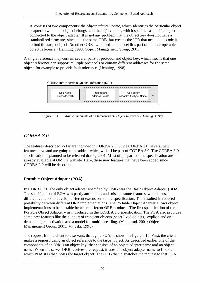
Integration of Heterogeneous Systems – A Component-Based Approach
- 92 -
It consists of two components: the object adapter name, which identifies the particular objectadapter to which the object belongs, and the object name, which specifies a specific objectconnected to the object adapter. It is not any problem that the object key does not have astandardized structure, since it is the same ORB that creates the IOR that needs to decode itto find the target object. No other ORBs will need to interpret this part of the interoperableobject reference. (Henning, 1998; Object Management Group, 2001)
A single reference may contain several pairs of protocol and object key, which means that oneobject reference can support multiple protocols or contain different addresses for the sameobject, for example to provide fault tolerance. (Henning, 1998)
Figure 6.14 Main components of an Interoperable Object Reference (Henning, 1998)
CORBA 3.0
The features described so far are included in CORBA 2.0. Since CORBA 2.0, several newfeatures have and are going to be added, which will all be part of CORBA 3.0. The CORBA 3.0specification is planned to be released during 2001. Most of the parts of the specification arealready available at OMG’s website. Here, these new features that have been added sinceCORBA 2.0 will be described.
Portable Object Adapter (POA)
In CORBA 2.0 the only object adapter specified by OMG was the Basic Object Adapter (BOA).The specification of BOA was partly ambiguous and missing some features, which causeddifferent vendors to develop different extensions to the specification. This resulted in reducedportability between different ORB implementations. The Portable Object Adapter allows objectimplementations to be portable between different ORB products. The first specification of thePortable Object Adapter was introduced in the CORBA 2.3 specification. The POA also providessome new features like the support of transient objects (short-lived objects), explicit and on-demand object activation and a model for multi-threading. (Mahmoud, 2001; ObjectManagement Group, 2001; Vinoski, 1998)
The request from a client to a servant, through a POA, is shown in figure 6.15. First, the clientmakes a request, using an object reference to the target object. As described earlier one of thecomponents of an IOR is an object key, that consists of an object adapter name and an objectname. When the server ORB receives the request, it uses this object adapter name to find outwhich POA it is that hosts the target object. The ORB then dispatches the request to that POA.

Integration of Heterogeneous Systems – A Component-Based Approach
- 93 -
The POA uses the object name to find out which servant it is that implements the target objectand then dispatches the request to that servant. The servant will then carry out the request anddeliver the result back to the client through the POA and ORB. (Vinoski, 1998)
Figure 6.15 Request to a Portable Object Adapter (Vinoski, 1998)
The POA supports two types of CORBA objects: the persistent object that was originallyspecified by CORBA, and a new short-lived object that is called a transient object. Persistentobjects have a lifetime that is independent of the lifetimes of any server processes in which theyare activated. Transient objects have a lifetime that is bounded by the lifetime of the serverprocess in which they’re created. This means, that when their server process die, the transientobject dies too. Transient objects involve less overhead than persistent objects, since there is noneed to keep any activation information for them. This kind of objects are useful in situationsthat only require temporary objects. (Schmidt & Vinoski, 1997; Vinoski, 1998).
The activation modes supported by the BOA were centred around server processes. The POAfocuses instead on CORBA object activation, and supports some different activation styles:
- Explicit activation: The server application programmer explicitly registers servants forCORBA objects by using direct calls on a POA.
- On-demand activation: The server application programmer registers a servant manager thatthe POA calls when it receives a request for an object that is not yet activated. The servermanager then decides what to do.
- Implicit activation: A request to a servant results in activation without any explicit calls tothe POA.
- Default servant: The application registers a default servant which will be used whenever arequest arrives for a CORBA object that is not yet activated, and there is no servantmanagers registered. (Schmidt & Vinoski, 1997; Vinoski, 1998)
The BOA specification did not describe how to manage multithreaded applications. The POAcan either be single-threaded or let the ORB control its threads. If the POA is single-threaded, thePOA will dispatch requests to servants in a serialized manner. The ORB-controlled model allowsthe underlying ORB to choose an appropriate multi-threading model, so that multiple requests tothe POA can be processed concurrently. Applications that use POAs for this model need to be

Integration of Heterogeneous Systems – A Component-Based Approach
- 94 -
able to handle multiple client requests simultaneously. Applications that use single-thread modelPOAs do not need to be thread-aware. (Vinoski, 1998)
The POA also supports separation of servant and CORBA object lifecycles, which means thatone CORBA object may be mapped to several servants during its lifetime, and one servant mayrepresent several CORBA objects. This is an important feature to contribute to scalableapplications. It means for example, that a database where each entry in the database is treated asa separate CORBA object, could have a single servant that gets the requested database entrywhen it is invoked, instead of having a separate servant for each database entry. (Schmidt &Vinoski, 1997; Vinoski, 1998)
CORBA Component Model (CCM)
CORBA 3 includes the introduction of a server-side component model (CORBA componentmodel, or CCM). CCM represents an extension and addition to the OMA and CORBA. TheCCM standard will allow greater software reuse and flexibility for dynamic configuration ofCORBA applications. This section presents some of the most important features of the CCMarchitecture.
Component
A component is the basic building block in CCM. It encapsulates a design entity and isreferenced by a component reference. The component type is an extension and specialization ofthe object type. Component types can be specified in IDL and represented in the InterfaceRepository. A component interacts with external entities, such as ORB services or othercomponents, through four different kinds of mechanisms, called ports:
• Facets (Provided interfaces): An interface contract exposed by a component. Facets allow acomponent to expose different views to its clients by providing distinct interfaces, that arenot related by inheritance. The implementation of the facets are encapsulated by thecomponent and not visible to clients.
• Receptacles: Provides a way for a component to connect to other objects, including objectsof other components, and invoke operations on those.
• Event sources/sinks: Enables components to interact by monitoring asynchronous events.Components can be either event source or event sink for one or more channels. Event sourcesare used for publishing events and event sinks are used for subscribing to events.
• Attributes: Are intended to be used for component configuration. At install time, thecomponent is configured to act in a particular way by setting the value of its configurationattributes. (Levine, Schmidt & Wang, 2000; Object Management Group, 1999, March;O’Ryan, Schmidt & Wang, 2000)
Components also have a single reference that supports an interface called the component’sequivalent interface, which is an interface that conforms to the component definition. There aretwo forms of clients that are supported by the CORBA component model: component-aware andcomponent-unaware clients. The component-unaware clients do not know that they are making a

Integration of Heterogeneous Systems – A Component-Based Approach
- 95 -
request to a component, and can therefore only invoke functions supported by an ordinaryCORBA object. The component-unaware clients can not use the ports, but can invoke operationsvia an object reference to the component’s equivalent interface. The equivalent interface caninherit from other interfaces, called the component’s supported interfaces. The equivalentinterface also provides the possibility for component-aware clients to navigate among thecomponent’s facets and to connect to the component’s ports. (Object Management Group, 1999,March)
The CCM divides components into four categories:
• Service componentsThese components have the lifetime of a single operation request. They represent the mosteffective component form, since they are cheap to create and destroy, and consume resourcesonly when active.
• Session componentsSession components can be called more than once, but they will not survive a server restart.These components can be used for functions that require keeping state during a clientinteraction, but do not require persistent storage, like for example iterators.
• Process componentsThese components are intended to be used for representing business processes, like applyingfor a bank account. A process component exists during the whole business process, even ifthere is a server outage, and maintains its state from one invocation to the next. When thebusiness process finishes the end result from the process becomes a product, like a bankaccount. So, the process component creates the product account component, and then frees upits resources and vanishes.
• Entity componentsThe entity components represent truly persistent items in an application, like customers andbank accounts. Usually, they represent data in a database. For entity components, a key isassigned to every component instance, to help in retrieving specific instances. (Brooke,Pharoah & Siegel, 2000; Levine et al., 2000; Object Management Group, 1999, March)
Component Home
A component home manages instances of a specified component type. Its interface providesoperations to manage component life cycles (create, destroy) and to find component instances forthe type it manages. At execution time, a component instance is managed by a single homeobject of a particular type. The operations on the home are comparable to static class methods inobject-oriented programming languages. All the operations that the developer might want todefine on the set of instances of a particular component type, should also be placed here. (ObjectManagement Group, 1999, March)
To use service and session components, a client will invoke the operation for creating a newinstance. The component home will return a reference to the client, that will be valid for a singleuse for the service component, and for repeated use for a limited time for the session component.For using process and entity components, a client may use the create-operation, but will usuallywant to access already existing components. For accessing an existing entity component, the

Integration of Heterogeneous Systems – A Component-Based Approach
- 96 -
client will use the find_by_primary_key()-operation on the component home. Processcomponents do not have primary keys, and therefore the client will have to store their referencesitself for future use. References may be stored in a client cookie or a Naming or Trader service.(Brooke et al., 2000; Levine et al., 2000)
Container
A container provides the server with a run-time environment for a CORBA componentimplementation. Each container manages one component implementation and connects it to othercomponents and ORB services. A container is a framework for integrating transactions, security,events and persistence into a component’s behaviour at runtime. (Object Management Group,1999, March)
The CCM Container Programming Model (see figure 6.16) defines a set of interfaces, thatsimplify development and configuration of CORBA applications. There are two categories ofinterfaces: external interfaces and container interfaces. The external interfaces are interfaces thatare available to clients, like supported interfaces, provided interfaces and the component homeinterface. The container interfaces include internal interfaces and callback interfaces. Theinternal interfaces can be used by the component to invoke the services provided by thecontainer. The callback interfaces can be used by the container, to invoke services on thecomponent. These interfaces must be implemented by the application developer. They carry outfunctions necessary to allow the server objects to be activated and deactivated by the container asit manages server resources. (Brooke et al., 2000; Levine et al., 2000; Object ManagementGroup, 1999, March).
The container architecture is a server-side framework, which is built on the ORB, POA (PortableObject Adapter) and a set of CORBA services for transactions, security, events and persistence.A component server is a process which provides an arbitrary number of component containers.The container framework manages the interactions with the ORB, POA and CORBA services,and lets the component developer concentrate on the application logic. The major functionalityhandled by this framework include creating object references (with the POA), giving access toHome operations, and interacting with the Transaction, Security, Persistence and Event services.(Object Management Group, 1999, March)
There are six container categories in CCM. Four categories correspond to the componentcategories; service container, session container, process container and entity container. Twocategories handle EJB components: the EJBSession container and the EJBEntity container. Thelast category is called the Empty container and makes all CORBA interfaces available to acomponent’s implementation without restriction. This gives the programmer the possibility todefine an own container, and to use any combination of the CORBA services. (ObjectManagement Group, 1999, October)
Transactions
The container provides access to a transaction processing system. The CCM supports bothcontainer-managed transactions (which is the simpler form to program), and self-managedtransactions. (Brooke et al., 2000)

Integration of Heterogeneous Systems – A Component-Based Approach
- 97 -
Security
The CCM provides a secure environment, which may be controlled via a componentconfiguration file. Access permissions can be defined for any of the component’s ports as well asthe component’s home interface. (Brooke et al., 2000)
Persistence
The container provides access to the CORBA Persistent State Service (PSS) for persistencesupport. There are two modes of PSS operation support; the container-managed persistencemodel, where the saving and restoring of an object’s state over a deactivation/activation cycle istransparent to the programmer, and the component-managed (self-managed) persistence, wherethe programmer must save and restore state explicitly before deactivation and during activationof the component. (Brooke et al., 2000; Object Management Group, 1999, March)
Events
The container also controls access to event channels, by using a simple subset of the CORBAnotification service. Operations for emitting and consuming events are generated from thespecifications in component IDL. The container is responsible for mapping these operations tothe CORBA notification service. (Brooke et al., 2000)
Figure 6.16 Container Programming Model (Object Management Group, 1999, March)
Integration of Heterogeneous Systems – A Component-Based Approach
- 98 -
Component Levels
There are two levels of components: basic and extended. The functionality described aboveapplies to extended components. Basic components have a subset of the functionality ofextended components. They do not offer facets, receptacles, event sources and sinks (onlyattributes). They may use transaction, security and partly use persistence, but not the eventmodel. The basic component is defined to be functionally equivalent to the EJB 1.1. ComponentArchitecture, to allow easy mapping between CORBA and EJB components. (ObjectManagement Group, 1999, October)
Component Implementation Framework (CIF)
CIF is a framework that defines the programming model for constructing componentimplementations. It uses a declarative language, Component Implementation DefinitionLanguage (CIDL), for describing the structure and state of component implementations. Fromthese CIDL definitions, a component-enabled ORB product should automatically generateimplementation skeletons, that automate some basic behaviours of components, such asnavigation, activation, lifecycle management, transactions and security, and that can be extendedby the developer to create complete implementations. (Levine et al., 2000; Object ManagementGroup, 1999, March)
Open Software Description (OSD)
Component implementations may be packaged and deployed. Open Software Description is anXML vocabulary for describing software packages and their dependencies. CCM uses anextended version of OSD to support component packaging and deployment. The deploymentmechanism allows remote installation and activation of a new or modified component. (Levine etal., 2000; Object Management Group, 1999, March)
Resource Management
At runtime, a CCM application will consist of a set of component homes, which createcomponent instances when required. CCM uses a pattern for resource allocation, calledactivation-per-invocation, that can be described by an example. Suppose we have an e-commerce application that consists of customer components (entity components), shopping cartcomponents (session components), and checkout components (service components). For everycustomer in the database, there is a customer component instance in our application. There willbe a shopping cart component instance for every customer who happens to be shopping at themoment. The checkout components are created when the customer presses the “check out”-button, perform their functions and disappear as soon as they are done. Let’s suppose we haveseveral millions of customers in our database. Then, it would not be efficient to have everycustomer and all present shopping cart instances in memory at the same time. Therefore, theCCM runtime manages the instances, by activating an instance when an invocation is made, anddeactivating it (and freeing its resources) as soon as the operation is completed. This
Integration of Heterogeneous Systems – A Component-Based Approach
- 99 -
activation/deactivation is invisible to the client application. Even if a customer component is notalways running, it is always available to the client. (Levine et al., 2000)
CORBA Scripting Language Specification
The Scripting Language Specification is a specification for how to enable the composition andassembly of components using scripts. The specification does not specify a specific syntax, sinceit should be general enough to encompass several object-oriented scripting languages. (ObjectManagement Group, 1999, August)
CORBA messaging
CORBA 2.0 provided three techniques for invoking operations:
1. Synchronous – The client invokes an operation and blocks waiting for the response.
2. Deferred synchronous – The client invokes an operation, then continues processing. It canlater go back and collect the response.
3. One-way – The client invokes an operation and then continues processing. There is noresponse.
Since synchronous invocation techniques tend to tightly couple clients and servers, CORBA hasbeen criticized for not being suitable for large distributed systems. For this reason, a newspecification (the CORBA Messaging specification) has been adopted, that adds twoasynchronous request techniques:
1. Callback – With each request, the client supplies an additional object reference parameter.When the response arrives to the ORB, the ORB uses this object reference to deliver theresponse back to the client.
2. Polling – The client invokes an operation, which returns an object that can be queried at anytime to obtain the status of the request. (Vinoski, 1998)
Objects by value
CORBA 2.0 lacks support for passing objects by value, instead of passing a reference betweenCORBA applications. This has led to the addition of a new construct to the OMG IDL, which iscalled the valuetype. A valuetype supports both data members and operations. When a valuetypeis passed as an argument to a remote operation, a copy of it will be created in the receivingaddress space. The identity of this copy is separate from the original; once the parameter passingoperation is complete, there is no relationship between the two instances. Operations invoked onvaluetypes are local, and unlike ordinary CORBA object invocations, they do not involve the
Integration of Heterogeneous Systems – A Component-Based Approach
- 100 -
transmission of requests and replies over the network. The “Object-by-value”-concept wasintroduced in CORBA 2.3. (Vinoski, 1998)
CORBA 3.0 Firewall Specification
This is a specification, which provides a standard for controlling IIOP traffic through networkfirewalls, to allow outside access to CORBA applications. It defines interfaces for a firewall toidentify and control the flow of IIOP traffic. It allows CORBA objects managed behind thefirewall to have operations invoked on them from the outside world, permitting access to someinside CORBA-based application services and preventing access to IIOP-based services thatshould not be accessible from the outside. (Object Management Group, 1998)
Implementations
CORBA is an open standard and anyone can implement it without having to obtain a licensefrom the OMG or anyone else. There are several CORBA-compliant products available in themarket from different vendors, for example the following three products, which are available fora large number of platforms and support Java and C++ bindings:
IONA’s Orbix
Orbix 2000 is fully compliant with CORBA 2.3, including POA and Object by value. It supportsparts of the CORBA 2.4 and CORBA 3.0 specifications, for example asynchronous messaging.(IONA, 2001)
Inprises’s VisiBroker
VisiBroker 4 is also fully compliant with the CORBA 2.3 specification and partly supports theCORBA 2.4 and CORBA 3.0 specifications. (Inprise, 2001) VisiBroker is also embedded inother products, for example in the Netscape Communicator browser.
BEA Systems’ WebLogic
WebLogic Enterprise 5.1 supports CORBA 2.2 and includes support for some CORBA 2.3extensions. (BEA Systems, 2000)

Integration of Heterogeneous Systems – A Component-Based Approach
- 101 -
Mapping to COM and EJB
The CORBA specification includes a chapter, which describes the data type and interfacemapping between CORBA and COM (OMG IDL vs. Microsoft IDL). The mapping wasdesigned to be implemented by automated interworking tools. This means that there will be animplementation of a bridge between the CORBA and COM system. Another way to access COMobjects from CORBA is to use a wrapper, which contains the required OMG IDL to expose theCOM object. But this requires development and maintenance of a wrapper server object forevery COM object and should only be used if there are a few COM objects that need to beaccessed. (Object Management Group, 2001)
The CORBA component model is based on the Enterprise Java Beans specification, extendingthe EJB component model with some additional features, such as a tighter integration with theCORBA object model. One of the design goals of the CORBA Components Model wascompatibility and interoperability with Enterprise Java Beans, to make it possible to formintegrated applications from EJB and CCM components. The CCM specification makes itpossible to make a CORBA Component appear as an enterprise bean, and to make an enterprisebean appear as if it were a CORBA component. One chapter in the CCM specification describesthe mapping between CORBA and EJB in detail. (Object Management Group, 1999, March)
How to develop a CORBA object, step by step
Here is a short step by step overview of how to develop a CORBA object and a client that canmake a request to the object. In this example, the Naming Service is used, but there are otherways to retrieve an object reference, as described earlier.
Server development steps
1. Write an IDL file that describes the object’s interface.Specify the object’s interface including its attributes and operations.
2. Run the IDL compiler.Choose the programming language that you will use to implement the object and run the IDLcompiler to generate the language-specific implementation files, client stub files and serverskeleton files.
3. Write the implementation of the object in the chosen language.Many IDL compilers generate a file that contains some of the code required to be a CORBAremote object, which can be extended by the programmer.
4. Write a server main program that acts as a server for the object.This program shall perform the following steps:- Initialize the ORB and the object adapter This means obtaining a reference to these objects.

Integration of Heterogeneous Systems – A Component-Based Approach
- 102 -
- Create an instance of the object- Tell the object adapter to connect the new object to the ORB- Find the Naming Service and assign the object a name This step is optional. It makes it possible for the client to find the object, by knowing the object’s name.- Wait for client requests
5. Compile the code.Compile all the generated code and the application code with a compiler for the chosenlanguage. (Benjamin et al., 1999)
Client development steps
1. Write a client application that invokes a request on the remote object.Choose which language to use for the client application. Then write a client application in thechosen language, that performs the following steps:- Initialize the client-side ORB- Find the Naming Service and look up the object This is one possible way to get an object reference. The client sends the name of the object as a parameter, and gets an object reference in return.- Make a request to the remote object Finally, the client makes an invocation on one of the object’s operations.
2. Compile the code.Compile the client application code with a compiler for the chosen language. (Benjamin etal., 1999)

Integration of Heterogeneous Systems – A Component-Based Approach
- 103 -
6.2 Other techniques
Today, the software component market is rapidly developing, and thereby its related integrationtechniques. There are some techniques under development, which might become key techniquesin the future. Here is a brief overview of three such techniques.
6.2.1 Jini
Jini is an object-oriented distributed architecture from Sun, which offers network “plug-n-work”.It provides an infrastructure for delivering services to clients in a network. A Jini system consistsof services that can be collected together for the performance of a particular task. Services canuse other services, and a client of one service may itself be a service for other clients. Servicescan be added or removed from the network, and clients can find existing services, without anyextra administration needed. Jini is written in Java, but clients and services are not constrained tobe in pure Java. They may include other programming languages, and have a wrapper written inJava that communicates with the rest of the system. (Newmarch, 2000; Sun Microsystems,2000b)
Fundamental parts of a Jini system
Service
A service is an entity that can be used by a client. Services can be devices, like printers or disks,software applications, databases or files. When a new service is plugged into a Jini network, itadvertises itself by publishing an object written in Java, that implements the service API, whichindicates what functionality the service provides. The protocol used for the communicationbetween this object and the service implementation, can be chosen by the programmer, and candiffer between implementations of the same service without changing the client code.(Newmarch, 2000; Sun Microsystems, 2001)
Client
An entity that wants to make use of a service. (Sun Microsystems, 2000b)
Lookup service (Service locator)
The lookup service acts as a locator between services and clients. A lookup service maps serviceobjects to the service implementation. There are also descriptive entries associated with a serviceto allow the selection of services, based on properties understandable to people. (SunMicrosystems, 2000b)

Integration of Heterogeneous Systems – A Component-Based Approach
- 104 -
Network
The network connects services, clients and lookup services. Although the Jini specification isindependent of the protocol used for network communication, the only current implementation isbased on the TCP/IP-protocol. (Newmarch, 2000)
Architectural Overview
There are three categories of components in a Jini system, that are the building blocks of the Jiniarchitecture: the infrastructure, the programming model, and services.
The infrastructure is the core of the Jini technology, and provides the resources that are neededfor executing Java programming language objects, for managing communication between theseobjects, and to make it possible to find and use different services in the network. Jini is based onthe Java programming language, and the environment provided for executing objects is the JavaVirtual Machine. Java RMI is used for communication between objects across the network. Adistributed security system is integrated into RMI and defines how entities are identified andgiven the right to perform actions in the system. The infrastructure also includes the look-upservice, which offers and finds services for clients, and discovery/join-protocols, which definehow a service of any kind becomes part of a Jini system. (Sun Microsystems, 2000b)
The programming model supports the production of reliable distributed services. It consists of aset of interfaces, for example the leasing interface, the event and notification interfaces and thetransaction interface. The leasing interface defines a way of allocating and freeing resources. Alease is a contract of guaranteed access to a service over a time period, which is negotiatedbetween the user of the service and the provider of the service. Leases can be exclusive or non-exclusive. An exclusive lease means that only one user has the lease during the agreed upontime. If a lease is not renewed at the expiration date, then the lookup service will remove theentry for it, and the service will no longer be available. The event and notification interfacesenable event-based communication between services. An object may allow other objects toregister their interest in events and receive a notification of the occurrence of such an event. Thetransaction interfaces supply a service protocol, that helps coordinating state changes of objects,in such a way that all or none of the changes to the group of objects are performed. (SunMicrosystems, 2000b)
Entries in the lookup service are leased, which ensures that the lookup provides an accurate viewof currently available services. When a service joins or leaves a lookup service, an event isemitted and those objects that have registered interest in such events get notifications. (SunMicrosystems, 2000b)
Services can be made part of a Jini system and offer functionality to clients. Services appear asobjects written in Java. A service has an interface, which defines the operations it provides toclients. Some services provide a user interface for direct user interaction; others only provideinterfaces to other applications. (Sun Microsystems, 2000b)

Integration of Heterogeneous Systems – A Component-Based Approach
- 105 -
Service Registration
A service will be an object (or set of objects), which is living within a server. To make a serviceavailable to potential clients, the server must register the service with the lookup service (servicelocator). This is done in the following steps (see figure 6.17):
1. The server finds a lookup service. If the server knows the location of the lookup service,the server can make a direct request to it, using unicast TCP (a specific destination isdefined). If it is not known, the server can make a multicast UDP request (deliversrequest to all receivers associated with the multicast group), which will make all availablelookup services respond.
2. The request to the lookup service, will cause the lookup service to return an object, calleda registrar, to the server. The registrar acts as a proxy to the lookup service, and will runin the service’s JVM. All further requests that the server needs to make to the lookupservice, will be made through this registrar. Usually, the protocol used for this is RMI.
3. The service will then send a copy of the service to the service locator, by making arequest to the registrar. (Newmarch, 2000)
Figure 6.17 Service Registration
Integration of Heterogeneous Systems – A Component-Based Approach
- 106 -
Client Lookup
A client who wants to use a service, will have to get a copy of the service into its own JVM. Thisis done in the following steps (see figure 6.18):
1. The client finds a lookup service, with the same mechanism that the server did.
2. The lookup service returns a registrar, that will be used for the client’s further communicationwith the lookup service.
3. The client requests a copy of the service to be created and distributed to itself. The request ismade through the registrar.
4. The service locator returns a copy of the service to the client. (Newmarch, 2000)
When the service locator has returned a copy of the service to the client, the client can makerequests of the service object running in its own JVM. If the service provided is a piece ofhardware, like a printer, or if the service is controlling some hardware, the copy of the servicewill not be a real copy of the original service. It will be a proxy, which will represent the service,by receiving requests from the client and communicating back to the service, usually using RMI.For the proxy service to find its service, the proxy will be “primed” with its own service’slocation when it is created. Exactly how this is done is not specified by Jini, and can be done inseveral ways. (Newmarch, 2000)
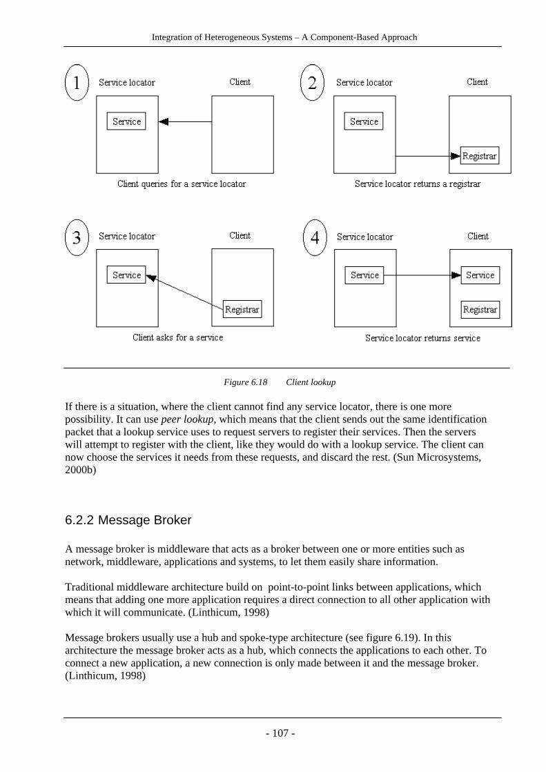
Integration of Heterogeneous Systems – A Component-Based Approach
- 107 -
Figure 6.18 Client lookup
If there is a situation, where the client cannot find any service locator, there is one morepossibility. It can use peer lookup, which means that the client sends out the same identificationpacket that a lookup service uses to request servers to register their services. Then the serverswill attempt to register with the client, like they would do with a lookup service. The client cannow choose the services it needs from these requests, and discard the rest. (Sun Microsystems,2000b)
6.2.2 Message Broker
A message broker is middleware that acts as a broker between one or more entities such asnetwork, middleware, applications and systems, to let them easily share information.
Traditional middleware architecture build on point-to-point links between applications, whichmeans that adding one more application requires a direct connection to all other application withwhich it will communicate. (Linthicum, 1998)
Message brokers usually use a hub and spoke-type architecture (see figure 6.19). In thisarchitecture the message broker acts as a hub, which connects the applications to each other. Toconnect a new application, a new connection is only made between it and the message broker.(Linthicum, 1998)

Integration of Heterogeneous Systems – A Component-Based Approach
- 108 -
Figure 6.19 Message broker with hub-and-spoke architecture
The message broker connects applications that may be written in different programminglanguages and reside on different platforms, by routing messages between them, and providingfunctionality for translating and reformatting messages. Message brokers use asynchronousmessaging. Applications put messages to the message broker and other applications get themessages. (Linthicum, 1998)
A message broker’s major purpose is to constitute a central integration point and to translatemessages and deliver them to the target applications. The message broker could be seen as aprocessing layer between different applications and platforms, which takes care of differences inapplication languages, data formats, and operating systems. By making all necessary conversionswithin the message broker, required changes to the source and target applications are kept at aminimum. (Linthicum, 2001a)
Message brokers can be seen as “middleware for middleware”, since it builds on existingmiddleware technology, most often on messaging middleware. When using traditionalmiddleware, there are components for routing, reformatting and co-ordination of messages thatare placed in the applications or in the middleware. These components are here instead placedcentrally in the message broker. (Linthicum, 1999)
A message broker should ideally be “any-to-any” and “many-to-many”. Any-to-any means that itmust be easy to connect different applications and other resources and the developer should beprovided with a consistent interface to the different resources. Many-to-many means that when aresource has been connected to the message broker, any other application should be able to useit. (Linthicum, 1999)

Integration of Heterogeneous Systems – A Component-Based Approach
- 109 -
Main elements
Message broker are sold by many vendors and have different options and styles. The termmessage broker is rather an architectural concept, than an off-the-shelf product. The coreservices that are provided by most message broker products are the following.
Message Queuing
A message broker is built around a message queuing system, which has the ability to accept,process and pass messages. Some message brokers provide proprietary message queuingcomponents, while others support different industry-standard products, like MQSeries fromIBM, Java Messaging Service from JavaSoft or the Object Messaging System from OMG.(Beveridge & Perks, 2000; Linthicum, n.d./2001a)
The message queue provides asynchronous, store-and-forward messaging. Store-and-forwardingmeans that the message broker stores messages until conditions are right to forward them to therecipients. If a connection fails during message transfers, message stores can recognize thefailure and retransmit the message when the connection is re-established. (Linthicum,n.d./2001b)
Message transformation
Most message brokers have a message translation layer, which understands all the differentformats of the messages that are passed among the applications and changes their formats. Itcontains a dictionary that keeps information on how each application communicates and whichinformation is relevant to which applications. (Linthicum, 1999)
There are two ways of transforming messages: schema conversion and data transformation.When two different application communicate, the message broker converts the message’s dataformats so they are interpretable by each application. This is achieved with schema conversion,which means changing the format of a message so that it is interpretable by the target system.Data transformation means simple conversion of data like aggregation or using lookup-tables.(Linthicum, 1999)
Most message brokers break the incoming message into a common format and then translates itinto an appropriate message format for the receiving system. This is performed by a rules-basedengine. The reformatting of the messages is defined by the programmer by using an interfaceprovided by the message broker. It could be an API or a more user-friendly GUI. The messagebroker stores application information in a repository that keeps track of the system where themessage is coming from, the message’s format, the target system, and the message format thatthe target system expects. (Linthicum, n.d./2001b)

Integration of Heterogeneous Systems – A Component-Based Approach
- 110 -
Message brokers are often able to understand a message schema through message identification,so it can automatically convert data to another format. Sometimes there will be a need for theprogrammer to define a rule for a specific data conversion, for example when convertingbetween numeric and alphanumeric data. (Linthicum, n.d./2001b)
Intelligent routing
Message brokers should have a rules-based engine that implements intelligent routing andtransformation. Intelligent routing means using predefined rules to dynamically route messagesto different applications. (Linthicum, 1999)
This means that the programmer is allowed to define how a message should be transformed androuted, depending on the format and content of a message. By knowing that a message with acertain format comes from a specific application, the programmer can define a rule, which tellsthe message broker that these messages shall be transformed according to some specific rulesand routed to a specific target application. (Linthicum, n.d./2001b)
Message warehousing
A message warehouse is a database that can store messages that passes through the messagebroker. By providing this facility, messages will not be lost at a server break-down, since thewarehouse acts as a persistent buffer or queue. The database can also be used for messagemining, to extract business data for supporting decisions. (Linthicum, 1999)
Repository services
A repository is a database that contains information about the target and source applications,such as data elements, the input, output and relationships between applications. The messagebroker uses these definitions to parse and process messages and for managing the message flowthrough the broker. (Beveridge & Perks, 2000; Linthicum, 1999)
Directory services
A mechanism that is used to locate the distributed applications and systems, which are connectedto the message broker. The directory service provides the location, identification, use andauthorization of network resources, such as source or target application. It supports using ashared set of directory and naming service standards. (Linthicum, 1999)

Integration of Heterogeneous Systems – A Component-Based Approach
- 111 -
Adapters
An adapter is a layer between the message broker interface and the source or target application,which adapts the differences between the application and the message broker’s native interfaces.It hides the complexity from the user and from the EAI developer. The adapters hide theapplication’s interfaces from the user and lets the user deal with the simplified interfaces instead.For example, a message broker may have adapters for several different major source and targetapplications (like SAP), or adapters for certain types of databases (like Oracle or Sybase). Itcould also have adapters for specific brands of middleware. Most message brokers offer softwaredevelopment kits to build new adapters. (Beveridge & Perks, 2000; Linthicum, n.d./2001a)
There are two types of adapters for message brokers, thin and thick adapters. Thin adapters mapthe interface of the source or target system to a common interface that is supported by themessage broker. Thick adapters also contain some functionality, to create an interface against theapplications to be integrated that requires almost no programming. Thick adapters use therepository services to get information of source and target applications for interacting with them.(Linthicum, n.d./2001a)
Adapters can also be classified as static or dynamic adapters. Static adapters must be manuallycoded with the schema for the applications. If the connected application’s schema change, staticadapters will have to be manually changed by the developer. Dynamic adapters use a discoveryprocess when they are first connected to an application, to find out their message schemas. Itmight involve looking in the repository and reading application source code. If later, somethingchanges in the message format for an application, a dynamic adapter will automaticallyunderstand these changes. (Linthicum, n.d./2001a)
Development environment
Message brokers may provide development tools to aid the creation of adapters. All messagebrokers provide an API to let the applications access the message broker and to put and getmessages from the message queuing component. (Beveridge & Perks, 2000)
Platform servicesMany message brokers are not completely self-contained. They require, or provide an option forintegrating with an organization’s standard platform services, like systems management,security, naming and addressing, communications and component-based services. (Beveridge &Perks, 2000)

Integration of Heterogeneous Systems – A Component-Based Approach
- 112 -
6.2.3 Intelligent Agents
There has been some research in the area of using intelligent agents for integratingheterogeneous software systems, and here two examples shortly will be described of how agentscan be used for this purpose.
There is no single universally accepted definition of what an intelligent agent is. One of the morecommonly used definitions is the Wooldridge and Jennings definition which says that an agent is“... a hardware or (more usually) software-based computer system that enjoys the followingproperties:
• autonomy: agents operate without the direct intervention of humans or others, and havesome kind of control over their actions and internal state;
• social ability: agents interact with other agents (and possibly humans) via some kind ofagent-communication language;
• reactivity: agents perceive their environment, (which may be the physical world, a user via agraphical user interface, a collection of other agents, the INTERNET, or perhaps all of thesecombined), and respond in a timely fashion to changes that occur in it;
• pro-activeness: agents do not simply act in response to their environment, they are able toexhibit goal-directed behaviour by taking the initiative.” (Jennings & Wooldridge, 1995)
Agent Adapters
The agent adapter architecture consists of a rules-based agent host and adapter components. Theagent host is an agent that functions as a host process for the application adapters and mediatesbetween the applications. Each adapter forwards messages from and to an application, and is ableto receive notifications from the application. (Yee, 1999)
The agent adapters differ from the message broker adapters in functionality. In the messagebroker architecture, adapters are responsible for interfacing with the applications. The messagebroker handles all the validation and transformation of data, and the adapters only pass messageswithout noting the contents of the messages. In the agent adapter architecture, the adapters arealso responsible for applying filters and performing validation of the data. By applying filters atthe node level instead of the hub level, less data will have to be sent over the network. Byremoving much of the complex processing from one central point, scalability can also beimproved. (Linthicum, 1999; Yee, 1999)
An agent adapter is also responsible for identifying the type and version of the application it isresponsible for and for applying the appropriate adapter component for integration. The agenthost is responsible for application session management, resource pooling, and managing state onbehalf of the adapters. Managing state is important for adapters that are interfacing totransactional systems. (Yee, 1999)

Integration of Heterogeneous Systems – A Component-Based Approach
- 113 -
Agent adapters can also use point-to-point interaction, which means that one agent directlyinitiates another agent adapter to perform a task. This could be useful when there is a task that isof little or no interest to other applications. This differs from the message broker architecture,where all communication is via the central broker. Facilities such as security, transformation,validation, and routing are available to each agent adapter. The agent adapter registers for theservices it is interested in at startup. A central repository manages information on eachapplication/agent adapter and information about the relationship of the information flow betweenindividual agent adapters. (Yee, 1999)
Intelligent Components
Another way to use agents for integrating heterogeneous systems is to take component-basedsoftware development one step further: to create intelligent components. Agent-based softwaredevelopment is similar to component-based development in many respects, but could lead toeven more flexible componentized systems, according to Martin Griss (2000).
An existing component could be turned into an agent by placing wrapper software around thecomponent, that presents an agent interface to the other software components and which mapsoutside agent calls to the legacy code and vice versa. (Jennings, 2001)
Griss describes an agent system reference model, that constitutes an architecture for agentcomponents. Just like the component frameworks include support services such as naming andtransaction support, the agent framework also supports these kinds of features.
The agent system architecture consists of the following parts (see figure 6.20):
• The Agency, which is the local environment (process or server) that provides basicmanagement, security, communication, persistence, naming and transportation of agents.
• The Agent Management System, which manages creation, deletion, migration, etc. of agentsand provides a service for naming and locating agents by name.
• The Directory Facilitator, which supports finding agents by their offered services.
• The Agent Communication Channel, which routes messages between local agents and agentslocated in other agencies.
• The Agent Platform, which provides the communication and naming infrastructure using theInternal Platform Message Transport. (Griss, 2000)

Integration of Heterogeneous Systems – A Component-Based Approach
- 114 -
Figure 6.20 Agent System Reference Model (Griss, 2000)
The intelligent components should have a simple interface, that is similar to all components, butallows messages to have a complex structure. This means that instead of having to change theframework and redefine the interfaces as the system evolves, the messages can be dynamicallyextended. (Griss, 2000)
In agent-based systems, the interaction between the agents usually occurs through a high-levelagent communication language. The interactions are conducted at the knowledge level, in termsof which goals should be followed, at what time and by whom, instead of operating at a puresyntactic level, as in the case of method invocations. (Jennings, 2001)
Agents are able to make context-dependent decisions about their interactions. For a complexsystem it is very difficult to predict at design time, all interactions that will have to take placebetween its various components. In agent-based systems the components have the ability to makedecisions about the nature and scope of their interactions at runtime. Each agent has its ownthread of control and has control over its own actions. This leads to a system consisting ofautonomous components that can act and interact in flexible ways to achieve their objectives.(Jennings, 2001)

Integration of Heterogeneous Systems – A Component-Based Approach
- 115 -
7 Interviews
We have performed four interviews with persons who have had direct or indirect contact withintegration questions. One of them was a senior lecturer in Chalmers Technical University inGothenburg, the second was a manager at Software Lab at Ericsson Microwave Systems inGothenburg, the third person was a systems developer at Ericsson Microwave Systems in Skellefteåand the last two persons worked at a small company in Gothenburg with Microsoft solutions for B2B(Business To Business). Each interview took about one hour and was semi-structured. Here is anabstract over these interviews. The interview questions, which were formulated as open questions,can be found in the Appendix.
7.1 Interview No. 1
The first person, the senior lecturer in Chalmers had not personally worked with any integrationproject but is well informed about distributed systems.
7.1.1 Integration Difficulties and Principles
The most difficult problem in an integration project, according to him, is that there is often notenough documentation or knowledge in the organization about the legacy systems. Or thedocumentation is very difficult to understand. There is often one or a number of such systems thatwill need to be integrated with the new ones in an integration project. Legacy systems could often beintegrated with help of middleware and using standardized interfaces. He meant that well-definedand “clean” interfaces are very important. He thought that design patterns are a good approach forintegrating components and mentioned the “facade” and “proxy” as useful patterns for this. He alsocommented that design patterns do not need to be object-oriented, but they have become popularwithin the area of object-oriented development. He said that the purpose of design patterns is to putnames on general solutions to certain problems, to provide developers with a common language.
He meant that there is nothing such as an optimal integration, since he did not think that there is onesolution to all problems. There will always be different systems with different specifications and anoptimal integration depends on the specific integration problem.
7.1.2 Component-Based Software Development
He was convinced that component-based software development has a bright future. As an example,he said that twelve years ago it was very difficult and costly to develop a graphical user interface or asimple database. Today it is easy and relatively cheap to do this, because we can buy componentsfrom different suppliers for this (database management systems and libraries for GUI-development).It is also relatively cheap to maintain those components, because when we upgrade them we just buy

Integration of Heterogeneous Systems – A Component-Based Approach
- 116 -
an upgrade from the supplier. The supplier can keep low prices, since there are many customerssharing the costs for development and upgrading. The same thing applies for “in-house” componentdevelopment: the components can often be used in different parts of the organization and then thedevelopment costs can be shared.
He also said that when buying components, there are some important factors to consider, except forthe technical aspects, for example what position in the market the supplier has. It could be dangerousto become dependent on components from a supplier with just a few customers. Then, there is a riskthat the supplier will disappear and no other company will be interested in upgrading thecomponents.
He gave the following definition of what a component is: a program part, which is isolated fromother program parts and can be accessed through a standardized interface. Usually components areexecutable, but a more primitive form of components could be non-executable. He meant that adatabase management system is a good example of a component and that a more primitive form ofcomponents are libraries for developing graphical user interfaces, which become harder coupled toother program parts.
He pointed out that this was his interpretation of the word component, and that it is a generalproblem that there is no commonly accepted definition for this concept.
7.1.3 Integration Techniques
On our question whether we can trust that the different integration techniques can handle what theypromise, he meant that in the computer world, you could never trust anything, especially when weare talking about new techniques. He supposed that the best thing is to wait, to see differentcomments about new techniques and use them first when they are well established on the market.
He did not know which of the techniques (COM, CORBA, EJB) was the most complex to learn. Hehad had students working with Enterprise Java Beans, and he knew that it took some time for them tobecome familiar with this technique and to be able to use it.
He also said that CORBA has the advantage of giving a language-neutral standardized way ofdefining interfaces between servers and clients. COM is a Microsoft standard and not useful outsidethe Microsoft world.
He had not heard anything about message brokers or JINI but thought that XML was an interestingnew technique for integration, since it defines both information and how the information should bestructured, which means that the receiver can be unaware of how the information should bestructured.
7.2 Interview No. 2
The second interview was with the manager at Software Lab at Ericsson Microwave Systems. Thisperson was working with research about software products that will be introduced to the defencewithin 10 - 20 years. Software Lab co-operates with other big companies in the world. They work

Integration of Heterogeneous Systems – A Component-Based Approach
- 117 -
with middleware technologies such as CORBA. They have had focus in their work to create anindependent platform, which makes it easy to use different heterogeneous products on one platform.
7.2.1 Integration Difficulties and Principles
The manager thought that the most important part of an integration project is specifying theinterfaces carefully. The trend is that different parts of systems are not all developed simultaneously.There will always be legacy systems.
He meant that middleware is a good pattern for an optimal integration and to use wrapping of legacysystems. A general problem in integration projects is the integration of components in differentprogramming languages. He thought CORBA IDL is a good way to specify interfaces since it islanguage-independent.
He recommended design patterns for a successful integration project. He meant that design patternsare very useful; because when we talk about design patterns we are talking about actual problems,what kind of structure is valid in a specific problem and about the interplay between elements.Design patterns are very powerful for this, because when we say a name like “proxy”, everyonedirectly knows what we are talking about. At Software Labs, they have arranged courses, discussingthe design patterns described by “the Gang of Four”, i.e. Gamma et al. (1995).
7.2.2 Component-Based Software Development
Regarding component-based software development, he thought it was interesting but did not see it asthe future paradigm. He meant that people look at object-orientation in the same way, but after all,object-orientation is just another way to organize things. And even if it is a powerful way oforganizing things, it does not help to activate or stimulate human creativity. Besides, the mostinteresting thing for us is not how components and objects are constructed and how they work. Wejust want to know what they do. We are interested in their services, and therefore he believed that thefuture paradigm will be based on loosely coupled services, where the user self can choose how tocombine the services (service-oriented software development). At Software Labs for example, theyhave been working with the development of a system using voice recognition, where the user quicklywill be able to request a service by giving a verbal command.
He defined a component as an underlying element that realizes a service.
7.2.3 Integration Techniques
He thought that EJB does not cover all the important areas for distributed components yet. He meantthat CORBA 3.0 is a much better alternative, even supporting “real time” transactions. One problemwith CORBA has been that many of the CORBA Services in the specifications have been difficult toimplement.

Integration of Heterogeneous Systems – A Component-Based Approach
- 118 -
He meant that both EJB and COM are very complex. The complexity depends to some degree on thedevelopment tool that is used. A disadvantage of COM is that it is owned and specified by Microsoft,as the only key player. The biggest problem with COM is its platform dependence. He mentionedthat there had been a German company, trying to implement a COM-solution for Solaris, but it neverworked very well. On the other hand, EJB is platform independent but language dependent (Java),which makes it difficult to combine them with each other. He meant that Sun has become a dominantplayer in the area, having EJB mapped to CORBA and being a key member of OMG.
He did not recognize the concept message broker, but he was familiar with JINI. He meant that JINIbuilds on the new service-oriented paradigm. For the user, components are not so interesting; it is theservices that can be used that are interesting. JINI is based on this philosophy: when printing a paperwith your computer it is usually not interesting to know what kind of printer you have. Theinteresting thing is the printer’s service, i.e. the service of printing papers for you.
7.3 Interview No. 3
The third person worked as a systems developer at Ericsson. For the moment, he was working withan integration project where they were using CORBA. He had previously been working withmanagement systems in Windows NT and had experiences of COM.
7.3.1 Integration Difficulties and Principles
When asked about which principles are the most important in an integration work, he said thatmaking “everything work” is not easy. The biggest problem is often that you do not have well-specified interfaces. For example, he said, in his current project they were working with standardsfor interface specification, but these standards were themselves not clearly specified.
As weaknesses that could be harmful for an integration work, he pointed out the interoperabilityproblems in CORBA. He meant that there were two such problems: the interoperability betweendifferent CORBA-implementations from different vendors and between different CORBA-versions.For example, there is a new data type in IDL, named valuetype in CORBA 2.3, which does not existsin previous versions (see the CORBA chapter for details). It means that there might be problems ifusing this valuetype and wanting interoperability with older CORBA-versions.
7.3.2 Component-Based Software Development
When asked about what he thinks of component-based software development, he said that he hadworked with ActiveX-components. He meant that on the Windows platform, CBSD is almost in solecontrol and he definitely thought it has a future.
He defined a component as a binary, which you can use without having any knowledge about itscontents and it can be integrated with help of tools (such as an ActiveX-component). A componenthas two types of interfaces: an interface for the component’s functionality and another for

Integration of Heterogeneous Systems – A Component-Based Approach
- 119 -
configuring the component, which gives you the possibility of managing and administering thecomponent with tools. A component does not need to be executable by it self. For example anActiveX-component does not execute by itself but you can place it in a container, which can makeuse of it.
7.3.3 Integration Techniques
We asked if the techniques like COM and CORBA keep what they promise. He said that for COM itis true that many programming languages can be used, but it is essential that the compiled codefollows a specific binary format, which requires compilers specifically designed for that. VisualBasic, Microsoft’s version of Java and C++ supports it.
He meant that it is practically possible to combine different integration techniques, for examplecreating a bridge between COM and CORBA. Such products already exist in the market, but ofcourse it leads to a higher complexity level in an integration work, and should be avoided wheneverpossible.
We asked him about his experiences about flexibility and complexity. He thought that CORBAhandles flexibility better than COM. In CORBA you can build operations that work as bridgesbetween COM and CORBA. It can count as a benefit for CORBA if you need to integrate CORBAwith COM. Besides, CORBA has several services such as naming service, event service, etc. Thereis not any equivalence for these in COM.
On the other hand many CORBA-implementations such as Orbix and VisiBroker do not have allthese services, which are defined in the specification. The most implementations just have a few ofthese services. He said that in his current project, they used a third-party software from OpenFusion,which has all the CORBA-services.
Also, COM can only be used on the Windows platform, while CORBA can be used on severalplatforms, even if there are much more CORBA implementations for Windows than for Unix or anyother platform.
He thought programming with COM is more complex and that it is easier for a beginner to learnCORBA. He also said that the manuals for both COM and CORBA are not easy to understand.
7.4 Interview No. 4
We had our last interview with two persons, in a company, which works with Microsoft solutions forB2B (Business To Business). They were almost only working with COM solutions.
Integration of Heterogeneous Systems – A Component-Based Approach
- 120 -
7.4.1 Integration Difficulties and Principles
When we asked them about the weaknesses that exist in an integration work, they said that the mostimportant and difficult thing in such as projects is describing standards for interfaces in a clear wayand to make sure they are followed.
7.4.2 Component-Based Software Development
They both thought that component-based software development is something that will become afuture trend. They meant that with the continuing development of the Internet and the increase ofdistributed computing, the use of components will also increase.
They said that they had never thought of how to define a component, but that it might be defined assomething that performs a specific task, and is written in a specific programming language.
7.4.3 Integration Techniques
They mentioned that it was a disadvantage for COM that there is only one key player (Microsoft)that has the total control and sets the standard but they meant that after all, COM really works well inthe Microsoft world.
Some times it is enough to divide a system’s tasks in a number of servers instead of collecting all ofthem in one centralized mainframe. For example you can have customer information in one server,order information in another one, etc. They meant that it is not just better to build a system in thisway but also with Internet, enterprises will automatically be, more or less, forced to re-design theirsystems in this way in the future, where enterprises will need to have different servers for differentservices, not just in different places in the company, but at different geographical locations in theworld.
They thought CORBA is a working solution for this but that it is very complex to use and that it doesnot manage security aspects very well. They thought that CORBA is a good solution for intranetsand local networks, but not for the Internet. Here, they thought, it is much easier to work with SOAP,which is a new technique for exchanging structured information in a decentralized distributedenvironment, using XML. But when large data volumes need to be distributed binary, they stillthought that CORBA is a better alternative. In their projects, they use SOAP for integrating theircustomers’ distributed environments with the customers’ partners’ environments, which might bebased on other platforms than Windows.
SOAP sends information in a well-structured way. The sender just sends a packet of information andtherefore there is not any heavy loading on the servers. The receiving computer takes care ofunpacking the information and making any necessary computations.

Integration of Heterogeneous Systems – A Component-Based Approach
- 121 -
8 Prototype
In this section, we will describe the objectives and requirements with our small prototype and thedifferent phases of the development process.
8.1 Objectives
During our literature study we have become familiar with three different techniques forcomponent integration, namely Enterprise JavaBeans, COM and CORBA. To better understandsome of the more detailed descriptions of the techniques, we decided to develop a simpleprototype with one of these techniques. The ideal approach would have been to develop aprototype with each of the techniques, but because of the time constraints we did not have thispossibility. We also hoped that hands-on experience from a prototyping process, would give us abetter understanding of the general problems involved in performing an integration task.
We decided to choose EJB, since that would give us a better understanding of the component-model of both EJB and CORBA (as we have mentioned earlier, their component-models aresimilar). At present, there is no implementation in the market that supports CORBA’scomponent-model. COM is a less interesting alternative to Ericsson, since COM is platform-dependent.
8.2 Requirements
The task we were given was to develop a simple prototype for a portal that would make itpossible for a network-operator’s customers to log in with user-name and password and viewtheir trouble tickets. A trouble ticket is a record of a problem that has occurred with a customer’snetwork-connection. There are different standard categories of troubles that can occur.
From the beginning, the intent was that we would make a connection to an existing database atEricsson, but these tables were difficult to interpret since they lacked understandable columnnames, had complex relationships and we did not have access to any documentation. Therefore,we decided to make a simple local database ourselves and define our own tables.
8.3 Tools/Installation
As development environment we have used Borland’s JBuilder 4 on Windows NT. JBuilder is atool that supports building applications in the Java language, applets, JSP/Servlets, JavaBeans,Enterprise JavaBeans and distributed J2EE applications for the Java 2 Platform. We usedBorland AppServer 4.5 to act as a runtime environment for our Enterprise JavaBeans and we

Integration of Heterogeneous Systems – A Component-Based Approach
- 122 -
used JDataStore 4, which came with JBuilder to manage our database. JDataStore is an objectrelational database management system2.
We had some installation problems with JBuilder, because JBuilder’s documentation did notexplain all the configurations that needed to be done to make JBuilder find the applicationserver’s libraries. When compiling our first beans, we had strange compilation errors, which wedid not understand had to do with an incomplete installation. Finally, we could solve thisproblem, with some help from a person who answered our question in one of Borland’s usergroups. JBuilder comes with the Java 2 Standard Edition SDK-libraries, but when developingEnterprise JavaBeans, the Enterprise Edition-libraries are required. There was no explanation forthis in the documentation and at first we did not realize that we had to download this ourselves.Because of these and some other problems, the installation process took much longer than wehad expected.
8.4 Training
We started to learn how JBuilder worked by creating some simple session beans and deployingthem in a container on the application server. JBuilder has wizards that simplify the developmentand deployment of beans. It supports the process of creating an “empty” bean (containing nobusiness logic) with a home and remote interface, and it creates a first version of an ejb-jar file,which will be used for deploying the bean.
We also tested to create some tables in JDataStore and learned how to create a simple entity beanfrom an existing database table. When we had this basic knowledge of the techniques we wouldbe using, we proceeded to the next step: modelling our prototype.
8.5 Modelling
We decided to have four database tables: Customer, User, Trouble Ticket and Ticket Type. Foreach database table we would create an entity bean. We decided to use container-managedpersistence, since it simplifies the mapping of the data in the beans with the underlying datastore.
The client application would contain the functionality to let a customer log in with a user nameand password, and to list trouble tickets for the customer. We decided to put the graphical userinterfaces as separate classes, to keep them separated from the functionality for a better overviewand changeability. To give the user some alternatives, we decided to add choices for listingtrouble tickets between a given start and end date and choices for specifying status and type ofthe trouble tickets of interest. The default end date would be the current date and the default startdate would be the date of the first trouble ticket for that customer that existed in the database. Wewould also have some error messages handling users specifying wrong username or passwordand typing unexpected date formats. We also decided to list customer information in the upperpart of the window. 2 An object relational DBMS is a hybrid that combines features of both relational and object-oriented databasemanagement systems.

Integration of Heterogeneous Systems – A Component-Based Approach
- 123 -
The connection between the client and the entity beans was implemented using CORBA.Borland’s AppServer builds on a CORBA-based infrastructure (VisiBroker), and provides aVisiBroker java2iiop compiler to enable RMI over IIOP. Using RMI over IIOP we could definethe interfaces in Java, letting the compiler create the necessary IDL. This was a chance for us tosee how the interoperability worked between EJB and CORBA. An overview of the flow ofrequests from the client application to the beans are shown in figure 8.1.
Figure 8.1 An overview of the flow of requests for our prototype
8.6 Programming
Finally, we started to create the database tables, the entity beans and the client application. Thisstep went quite fast and problem-free, since we now had all the knowledge needed to developour prototype. The main graphical user interfaces for the client application are shown in figure8.2 and 8.3.
EnterpriseBean 1
HomeInterface
EJBObject
RemoteInterface
For Bean2
2
4
5
7
6
8
AppServer
Client
1
3
Database
1. Request for creation of a new EJB object2. An EJB object is created3. EJB object reference is returned to client4. A method-call5. The method-call is delegated to the Bean6. Communication with database7. Value of method-call returns8. Value of method-call is routed back to client
EnterpriseBean 2
EnterpriseBean 3
EnterpriseBean 4
USER
username*passwordcustomerId
CUSTOMER
customerId*nameaddressphone
TICKETTYPE
typeId*typeNamedescription
TROUBLETICKET
troubleId*typeidcustomerIdprioritystatedatedescription
HomeObject
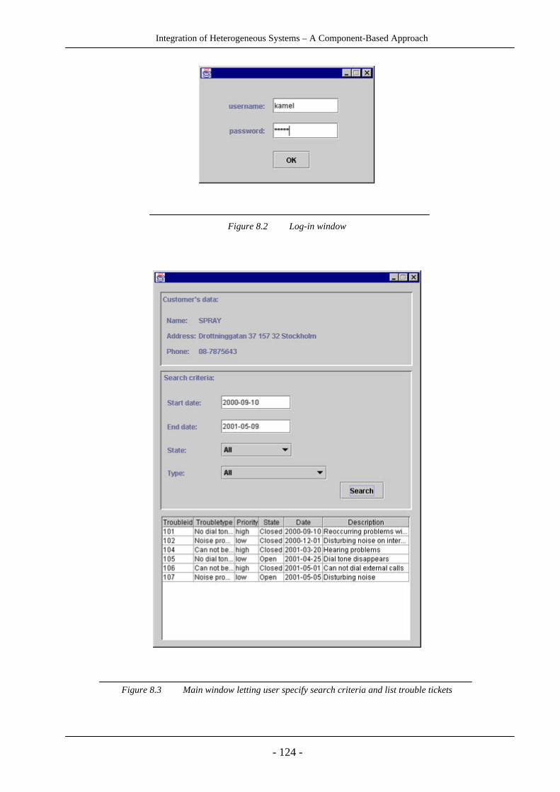
Integration of Heterogeneous Systems – A Component-Based Approach
- 124 -
Figure 8.2 Log-in window
Figure 8.3 Main window letting user specify search criteria and list trouble tickets

Integration of Heterogeneous Systems – A Component-Based Approach
- 125 -
9 Results
In this section we will present our results, categorized after each method we have used: theliterature study, the interviews and the prototype development.
9.1 Results from literature study
9.1.1 Some points from the literature analysis
• In the last few years a new paradigm in the area of software development has beenrecognised, namely Component-Based Software Development (CBSD). It focuses on therealization of systems through integration of pre-existing components and shifts thedevelopment emphasis from programming software to composing software systems.
• Four major activities characterize the component-based development approach: componentqualification, component adaptation, assembling components into systems, and systemevolution.
• The selection of a particular architectural style, or the invention of a custom style, is perhapsthe most important design decision affecting the integration process. In fact the architecturewill drive the integration effort.
• A design pattern is a description of a well-proven solution to a general design problem that mayoccur in many different situations.
• Design patterns are not only useful for the design of object-oriented systems. Some designpatterns could be used at the software component level, for component integration. Thosepatterns that we have found suitable for application in this area are the adapter, bridge, proxy,mediator and facade patterns described by Gamma et al. (1995), the broker and layer patternsdescribed by Buschmann et al. (1996), and the Component Interaction Patterns described byEskelin (1999).
• There are three dominating techniques in the area of software component integration, namelyEnterprise JavaBeans, COM and CORBA.
• In addition to these techniques, there are several other techniques under development, whichmight become more widely used in the future. Some examples are JINI, message brokers andintelligent agents.

Integration of Heterogeneous Systems – A Component-Based Approach
- 126 -
9.1.2 Comparison of the dominating techniques
Here, we will give an overview of similarities and differences between Enterprise JavaBeans,COM and CORBA. To make a meaningful comparison, we need to compare the parts of thearchitectures that are on the same level, covering the same area of use. First, we will present acomparison between the component-models, namely MTS, EJB and CCM. Then we will give acomparison of the three distributed architectures DCOM, CORBA and RMI.
MTS vs. EJB
Architecture
The general architecture of MTS and EJB are very similar. As with MTS, EJB supports serverapplication assembly.
A basic architecture of EJB and MTS can be described as follows:
MTS Architecture EJB Architecture
• The mtx.exe • An EJB server
• The MTS Executive (mtxex.dll) • EJB containers that run within the server
• The Factory Wrappers and ContextWrappers for each component
• Home objects and Remote EJBObjects
• The MTS Server component • Enterprise Beans, which runs within thecontainer
• Support systems like the Service ControlManager (SCM), the Microsoft MessageQueue (MSMQ), etc.
• Support systems like Java NamingDirectory Interface (JNDI), JavaTransaction Service (JTS), etc.
While EJB Components run inside an EJB Container, MTS components run in an MTS Executive.The MTS runtime (mtxex.dll) manages creation, management, and destruction of MTS componentslike an EJB container, which creates, manages, and destroys EJB components.
Both MTS and EJB work by intercepting method calls and inserting services based on a set ofattributes defined at deployment time. MTS uses class factory wrappers and object wrappers tointercept the method calls (the MTS executive is called automatically by the COM runtime).Similarly, EJB requires wrappers for each component type (EJBHome) and each component instance(EJBObject).
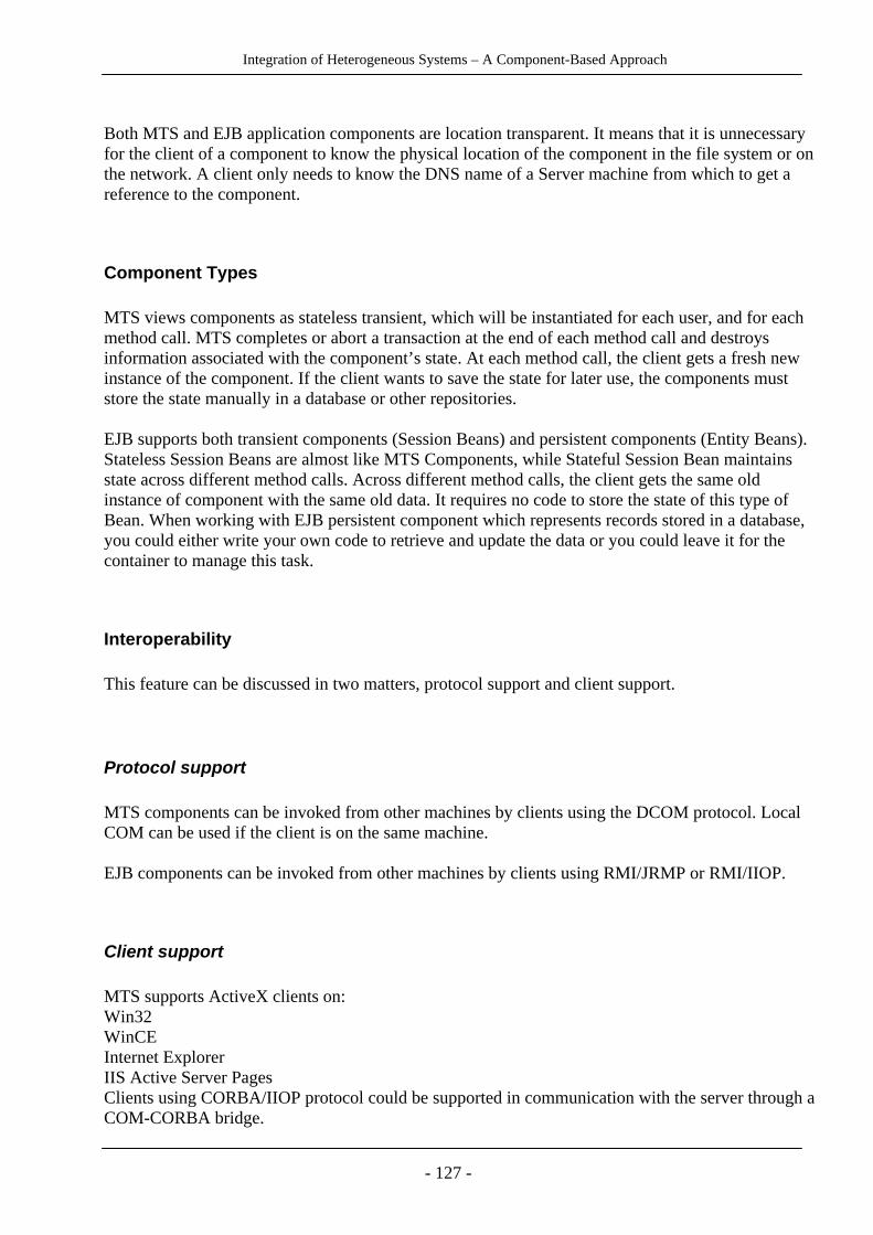
Integration of Heterogeneous Systems – A Component-Based Approach
- 127 -
Both MTS and EJB application components are location transparent. It means that it is unnecessaryfor the client of a component to know the physical location of the component in the file system or onthe network. A client only needs to know the DNS name of a Server machine from which to get areference to the component.
Component Types
MTS views components as stateless transient, which will be instantiated for each user, and for eachmethod call. MTS completes or abort a transaction at the end of each method call and destroysinformation associated with the component’s state. At each method call, the client gets a fresh newinstance of the component. If the client wants to save the state for later use, the components muststore the state manually in a database or other repositories.
EJB supports both transient components (Session Beans) and persistent components (Entity Beans).Stateless Session Beans are almost like MTS Components, while Stateful Session Bean maintainsstate across different method calls. Across different method calls, the client gets the same oldinstance of component with the same old data. It requires no code to store the state of this type ofBean. When working with EJB persistent component which represents records stored in a database,you could either write your own code to retrieve and update the data or you could leave it for thecontainer to manage this task.
Interoperability
This feature can be discussed in two matters, protocol support and client support.
Protocol support
MTS components can be invoked from other machines by clients using the DCOM protocol. LocalCOM can be used if the client is on the same machine.
EJB components can be invoked from other machines by clients using RMI/JRMP or RMI/IIOP.
Client support
MTS supports ActiveX clients on:Win32WinCEInternet ExplorerIIS Active Server PagesClients using CORBA/IIOP protocol could be supported in communication with the server through aCOM-CORBA bridge.

Integration of Heterogeneous Systems – A Component-Based Approach
- 128 -
EJB supports:Java clients on any platform through RMICORBA clients on any platform through IIOPWeb clients through Java Server Pages and servletClients using COM+ protocol could be supported in communication with the server through a COM-CORBA bridge.Beyond this one EJB server implementation, namely WebLogic supports ActiveX clients.
Transaction Support
MTS supports four types of transaction attributes:
• not supported (the method does not support transactions)
• supported (the method can support the transaction, but it does not require one)
• requires (the method requires a transaction, if the caller does not provide one it will create one)
• requires new (the method always requires a new transaction)
EJB supports the same transaction types, and offers two new types:
• mandatory (the method requires that the caller provides a transaction)
• Bean-managed (the Bean manages its own transactions, specifying its own transactiondemarcation)
Portability
Since MTS is a component model for Windows NT and 2000, MTS components are portable onlyacross these platforms.
Portability for EJB components can be discussed in two different levels, namely:platform level and between different EJB servers/containers.
Since EJB components are developed in the Java language, there is no limit for portability acrossdifferent platforms.
In theory, EJB components can be ported to any EJB-compliant application server. But since theinterface between server and container has been left open in the EJB specification, there may besome difficulties, especially regarding container managed persistent Entity Beans. However,different EJB servers are available from BEA Systems, Bluestone, Gemstone, Borland andPersistence.

Integration of Heterogeneous Systems – A Component-Based Approach
- 129 -
Language support
MTS supports C, C++, Cobol, Visual Basic, Delphi, and practically any other development language.
EJB supports Java only.
EJB vs. CCM
The architecture of CORBA’s component model is very much similar to the component model ofEJB. Therefore, we will not go in to any detailed technical comparison between these two models.CCM provides two component levels, where the basic component provides the same functionality asan EJB component, and the extended component adds some extra features.
Architecture
The extended model of CCM adds facets, receptacles, event sources and sinks as new ways for acomponent to interact with external entities. In the extended model, components also can utilize theevent model of CCM. The session and entity components of CCM correspond to the session andentity beans of EJB. CCM also supports two more component types, service and processcomponents.
Portability
The EJB specification assumes that the components and containers/servers will be run on platformsthat already have the Java Virtual Machine installed. The CCM specification assumes that thecomponents and containers/servers can run on any platform.
Language support
The major difference between these two component models is their language support. EJB is suitedonly for the Java language, while CCM intends to ease the integration of heterogeneous componentsby supporting components developed in various programming languages.

Integration of Heterogeneous Systems – A Component-Based Approach
- 130 -
CORBA, DCOM & RMI
CORBA, DCOM and Java RMI provide the infrastructure needed for clients and objects tocommunicate in a distributed environment. Their architectures are based on the same basic concepts.They all use an object-oriented RPC-based (Remote Procedure Call) form of communication. Toinvoke a remote operation, the client makes a call to the client stub (called proxy in DCOM), whichpacks the call parameters into a request message, and sends the message. At the server side, themessage is unpacked by the server stub (called skeleton in CORBA and RMI), and sent to the targetobject’s operation.
Still, there are some differences between the three architectures. The following table summarizesdifferences and similarities for the three architectures and some of them are described in more detailbelow.
CORBA DCOM Java RMISupport fordifferentprogramminglanguages
Can be used withany programminglanguage that hasan IDL mapping.
Can be used withdifferentprogramminglanguages, since thespecification is at thebinary level.
Supports Java only.
Platformdependence
Will run on anyplatform that hasa CORBAimplementation.
Will run on anyplatform that has aCOM serviceimplementation.
Will run on anyplatform that has aJava VirtualMachineimplementation.
Underlyingprotocol
IIOP (InternetInter-ORBProtocol)
ORPC (ObjectRemote ProcedureCall)
JRMP (JavaRemote MethodProtocol)
Distributedgarbagecollection
No Yes. Performsgarbage collection bythe use of a pingingprotocol.
Yes (using themechanisms in theJava VirtualMachine).
InterfaceDefinitionLanguage
OMG IDL MIDL (MicrosoftIDL)
Java
Multipleinterfaces/Interfaceinheritance
Supports multipleinheritance forinterfaces.
Supports severalunrelated interfacesfor the same object.
Supports multipleinheritance forinterfaces.
Exceptionhandling
Allows throwingCORBA standardexceptions, anduser-definedexceptions inIDL, which are
Each method callreturns a bit stringwith return status.Uses Error Objectsfor richer exceptionhandling.
Allows throwingexceptions, whichare serialized andmarshaled.

Integration of Heterogeneous Systems – A Component-Based Approach
- 131 -
serialized andmarshaled.
Name mappingto objectimplementation
Handled by theImplementationRepository.
Handled by theRegistry.
Handled by theRMIRegistry.
Typeinformation foroperations
Is held in theInterfaceRepository.
Is held in the TypeLibrary.
Is held by theobject itself.
Responsibilityfor locating anobjectimplementation
Object RequestBroker
Service ControlManager
Java VirtualMachine
Pass object byvalue
Yes Yes Yes
Dynamicinvocation
Yes Yes Yes
CORBA and DCOM both support different programming languages. Java RMI is an extension to thecore Java language and depends on many of the features of Java like object serialization and Javainterface definitions. Java RMI can only be used in a distributed environment, where all the serverand client objects are written in Java. If legacy systems need to interface with RMI systems, adaptershave to be written to the older systems.
CORBA and DCOM both use their own variant of IDL for defining interfaces. RMI does not use anyseparate interface definition language. Instead it uses Java for this purpose. By using IDL, CORBAand DCOM separates interface definition from implementation, which leads to the possibility ofusing different programming languages for the object implementations.
Reference counting provides a mechanism that allows an object to keep track of its clients andenables it to delete itself when it is no longer needed (that is, when there are no references to theobject. DCOM and Java RMI support reference counting for distributed garbage collection. InCORBA, there is no count of object references, and object deletion can only be done by explicitapplication programming by the developer. CORBA allows a client to convert an object reference toa string, and later converting it back to a usable object reference. Since object references converted tostrings not are included in reference counting, it would not work well to both provide object-to-string/string-to-object capabilities and reference counting.
CORBA and Java RMI support interface inheritance. DCOM does not support this feature, butinstead allows an object to have several interfaces to the same object, which allows each distinctfeature of an object to have a separate interface.

Integration of Heterogeneous Systems – A Component-Based Approach
- 132 -
9.2 Results from interviews
9.2.1 Integration Difficulties and Principles
• The major problem in an integration work is the lack of a good understanding and insight overinterfaces. It means that interfaces are either not well specified, or there are not enoughdocuments about them (this holds more for legacy systems), or the documentation is written in away that does not give a good description over the interfaces (this holds more for modernsystems).
• Design patterns are useful for software component integration. Design patterns give thedevelopers a common concept base, and represent solutions to general design problems.
9.2.2 Component-Based Software Development
• Component-based software development seems to be an increasing trend, which bringsadvantages such as quicker development time, less costs, and easier upgrading and replacementof system parts.
• Component-based software development is no silver bullet, though. It will not solve allproblems. CBSD could be seen as a powerful way of organizing things, but for example, it doesnot support human creativity.
• There is not a commonly accepted definition of what a component is. All the interviewees gavetheir own definition of this concept, which seemed to be affected by the kind of components theypersonally had come in contact with.
• In future there might be more focus on another paradigm; service oriented software development,where the focus is less on components and how they are constructed, and more on the servicesthat these components offer and their quality.
9.2.3 Integration techniques
• Integration techniques like CORBA, COM and EJB are all complex techniques, which requiremuch training from the developer to learn and to be able to use effectively. A well-designeddevelopment-tool can simplify the use of the techniques, and reduce the training needed.
• It is possible to make techniques such as CORBA and COM to interoperate, but it results in ahigher complexity in the integration work.
• The CORBA specification covers many useful services, but most vendors have onlyimplemented a limited number of these services.

Integration of Heterogeneous Systems – A Component-Based Approach
- 133 -
• It is true that COM works with different programming languages, but it requires compilers,which compile the code according to a specific binary format. Those programming languages,which do not have such compilers, could not be used with COM.
• CORBA could be seen as more flexible than EJB and COM regarding some aspects. It supportsmany different platforms and different programming languages, and many additional serviceslike trading and event service.

Integration of Heterogeneous Systems – A Component-Based Approach
- 134 -
9.3 Prototyping experience
The development of a simple prototype using Enterprise JavaBeans gave us a much betterunderstanding of the theoretical descriptions of EJB’s architecture, and of the process of developingand deploying beans in a runtime environment. We could easily relate this to the architecture ofCORBA, since CORBA’s Component Model is an extension of EJB’s.
We were also able to draw some more general conclusions about this kind of integration techniques,which are summarized below.
9.3.1 Development Tool Demanding
Using a development tool such as JBuilder for creating and deploying components means that a lotof work could be automated (for example the creation of the home and remote interfaces and thecreation of the ejb-jar file). It also lets the developer deploy the beans in the application server fromwithin this development environment. Other useful features are help with keeping backup copies andversion tracking of files.
Even for small projects, there will be a large number of source files when developing enterprisebeans. Our simple prototype resulted in 48 java source-files and 71 class files, where a large numberconsisted of CORBA-classes, like stubs and skeletons. To manage such a large amount of files couldbe complex without a suitable development tool.
For these reasons we think it is necessary to use a development tool for component development anddeployment, to be able to work efficiently and to have control over the process.
9.3.2 Development Tool Dependence
Our biggest problem during our prototyping process was the installation of JBuilder, and tounderstand the logic of JBuilder and how it acted in different situations. We had some problems withmenus sometimes disappearing or getting locked, strange compilation messages pointing at errors infiles that JBuilder self had created, etc.
Even if we had many troubles as a direct result of using JBuilder, JBuilder also had many advantagessuch as the wizards helping to develop and deploy simple enterprise beans. Choosing anotherdevelopment environment would probably have led to other experiences of what was the easy andmore difficult steps in the development process, depending on the benefits and drawbacks of thespecific development tool. Thus, the development tool is an important factor when evaluating thedifficulty and complexity of a specific technique for component development and integration.

Integration of Heterogeneous Systems – A Component-Based Approach
- 135 -
9.3.3 Interoperability with CORBA
During our literature study, we read about how to combine EJB and CORBA. The CCMspecification contains a chapter describing the mapping between EJB and CORBA. Using CORBAfor the communication between the beans and the client gave us an opportunity to see how thedescribed interoperability worked in reality. The development process was not complicated by thischoice: all we had to do was to compile the home interfaces with the VisiBroker compiler. TheCORBA IDL interfaces were generated automatically in the background from our Java interfaces;we did not have to make any special considerations to handle the CORBA communication. So forthis simple prototype the interoperability worked entirely without problems, with JBuilder and theAppServer transparently managing the mapping between EJB and CORBA at development anddeployment.
9.3.4 Inherent Technique Complexity
EJB is a complex technique. There are many new concepts to learn for a beginner before being ableto use the technique, like home and remote interfaces, deployment descriptor, ejb groups, stubs andskeletons, container, session and entity beans, naming service, narrowing, transaction management,etc. Therefore, a developer not familiar with component-based integration techniques will need sometime for learning these underlying concepts. When the developer has this basic knowledge and hassucceeded to create and deploy some simple session and entity beans, this process will be easilyrepeated though, especially if using a tool that automates much of the repetitive work.
9.3.5 Support for basic information management services
EJB’s support for transaction management, persistence and security simplifies the work needed to bedone by the developer. When developing the entity beans, we only needed to specify a databasedriver, the location of our database and a few other parameters. The actual calls to the database wereautomatically generated and hidden from our view, which greatly simplified our work.
9.3.6 Performance
We have worked with Windows NT, 128 MB RAM which is the minimal requirements for theBorland AppServer. The time required for deploying our four entity beans varied between a fewseconds and sometimes up to two minutes. What this variation depended on is unclear, but it usuallyhelped to restart the computer when the process became too slow. The communication between theclient and the server was also sometimes very slow.

Integration of Heterogeneous Systems – A Component-Based Approach
- 136 -
10 Discussion
In today’s turbulent and rapidly changing information society, having flexible and updatedinformation systems becomes a critical factor for the survival of many enterprises. To be able tooffer such solutions, the IT organizations are increasingly confronted with integration problems. Theneed for integration appears in various forms, such as integration with legacy systems or buildingsystems consisting of integrated third-party products. Because of its often-vital importance for theenterprise as a whole, IT-organizations, especially at the leadership and management level, mustconsider these questions at a strategic point of view, and give them a high-level priority.
We think that working with such questions cannot be done with the traditional developmentmethods. It needs a new way of thinking, having a component-based perspective. Just choosing anew technology is not sufficient to overcome the difficulties involved in integration tasks.
10.1 A critical view on our work
To answer the question of how to make Ericsson’s third-party products become successfullyintegrated we did not have the possibility to analyse the different involved systems in this missionbecause of their complexity, regarding the number of involved systems, their size and interrelations.
It was not easy to find the right path and depth of research for our work, especially during the firstweeks. Another problem was the different outlook, which the university and Ericsson had over thesame mission.
With respect to these reasons, we decided to have a macro view over the problem area. In thebeginning of our work, we tried to get a better understanding over our role in this integration effortusing the Zachman table (see the Appendix) placing our selves in the distributed system architecture,taking a design perspective and focusing on distributed architectures.
As a consequence to this choice, we chose to study dominating principles and techniques forsoftware component integration. At the same time we tried to see other thinkable techniques, whichcould be used in integration projects.
To perform interviews in a way that leads to qualitative results, needs both experience and routine.Our limited earlier experience in this area could be seen as a lack in our research. Another limitedresource has been the time aspect. If we would have had more time, we could have developed oneprototype for each integration technique, providing us with more detailed material for making acomparison of the techniques regarding aspects such as performance and difficulties of learning.
10.2 Conclusions
Here, we will present the conclusions we have drawn from our results, regarding our three mainquestions for this thesis work.

Integration of Heterogeneous Systems – A Component-Based Approach
- 137 -
10.2.1 Question 1
What dominating general principles exist for software component integration and what are theirbenefits and drawbacks?
To be able to answer this question, we first tried to find a definition of the concepts componentand integration. As we soon realized, these concepts have many different definitions and there isnot a single true and all agreed-upon definition. In chapter four we gave a number of directdefinitions of component and also gave an indirect definition, by contrasting a component to thedefinition of an object. In chapter five, we discussed the terms system, integration, architectureand their relationships, and concluded among other things that integration to a high degree is amatter of architecture.
We found during our literature studies, that the dominating principles that are used forintegrating software components are design patterns. We have studied some of the more well-known design patterns, and described those patterns we found applicable to the area ofcomponent integration, like adapter, bridge, mediator and broker, including their benefits anddrawbacks, in chapter five.
That some design patterns are useful for component integration was also later confirmed in ourinterviews. When studying the different integration techniques, we could also see ourselves thatthese techniques are built upon some of the design patterns. For example, CORBA is built on thebroker pattern, message brokers are built on the mediator pattern and the registrar in JINI is builton the proxy pattern.
10.2.2 Question 2
What different integration techniques exist for this purpose and what are the main differencesbetween them?
Middleware Component Models take a high level approach to building distributed systems. Theyfree the application developer to concentrate on programming only the business logic, whileremoving the need to write all the "plumbing" code that is required in any enterprise applicationdevelopment scenario. For example, the enterprise application developer no longer needs to writecode that handles transactional behaviour, security, database connection pooling or threading,because the architecture delegates this task to the server vendor. There are three dominatingMiddleware Component Models, namely Microsoft Transaction Server (MTS) Architecture, Sun’sEnterprise JavaBeans (EJB), and OMG’s CORBA Component Model (CCM).
EJB technology and CORBA are not really competitors. EJB makes it easier to build application ontop of a CORBA infrastructure, where CORBA handles the transaction and EJB the business logicwith the biggest advantage that CORBA works with all programming languages. Additionally, therecently released CORBA component specification is based on the EJB architecture.
Both Microsoft Transaction Server and Enterprise JavaBeans target the creation of component-based, transaction-oriented applications. Both of them support transactional applications and provideservices for scalability and can also be defined as component-based programming model. Becausethe two technologies attempt to solve many of the same problems, they have much in common.

Integration of Heterogeneous Systems – A Component-Based Approach
- 138 -
Almost all of the techniques that are used in an integration work are complex and tool-dependent.But the core of techniques such as EJB is in another level of complexity compared to the complexitythat a developer meets in his/her developing work. The last one depends on the tools that a developeruses in his/her work. In other words you can use a complex technique in a relatively easy way andvice versa.
As an example, Microsoft MTS has fewer development options than EJB does. Therefore MTSdevelopment might be experienced as easier. But most EJB development environment has tools suchas graphic wizards that generate almost all EJB constructs automatically. It means that theapplication developer experiences the task of development as easy and has no need to be involved inthe deep of complexity behind the technique.
MTS’s biggest weakness is that it is tied exclusively to Windows NT and 2000, which limits itsapplication in many systems requiring multiple platforms. EJB’s and CORBA’s biggest strength isthat they are available on lots of different operating systems. This diversity means that EJB- andCORBA-based applications can also run on systems that are bigger and more reliable than NT-systems.
EJB supports only a single programming language, namely Java. It is not reasonable to assume thatone language will ever be the right choice for every organization and every application, andtherefore, by tying itself to a single language, EJB limits it reach.
EJB defines support for two kinds of components (two kinds of enterprise beans). In addition tosession beans, which are much like MTS components, EJB’s second option, known as entity beans,has no analogue in MTS. Taking this approach, makes it easier for application developers to load andstore the components’ state and to manage their persistence. It makes it possible to createcomponents that are portable across any datastore.
The EJB specification leaves some details undefined, such as the relation between server andcontainer, which could harm the portability between different vendor implementations.
10.2.3 Question 3
For the specific operating support system at Ericsson Telecom Management, we had thefollowing question:How can their third-party products be integrated successfully, supporting simple replacementand maintenance?
We have the following suggestions for how Ericsson can continue the work with making theirsoftware solutions having a more flexible integration architecture:
• One problem involved with integration questions is that there does not exist common definitionsover different concepts. Therefore, arranging/creating a common concept base could be useful. Itis also important to have a common and clear definition of the problem, because the clearer theproblem definition is, the more easily we understand what we should do and what we should notdo. Having clear definitions of common concepts and of the problem in general is an importantstarting point, even if it is not enough in itself.

Integration of Heterogeneous Systems – A Component-Based Approach
- 139 -
• There exist a number of techniques for software component integration. Every technique sooneror later becomes obsolete and new techniques will continue to arrive on the market. To be able tochoose a suitable technique, it is important to specify what is needed in more abstract terms,without defining the needs in terms of a specific technique. A guidance model could help tofocus on which aspects are important when choosing a specific integration strategy. There is nointegration technique, which is the best solution for every integration task; the choice isdependent on how aspects such as flexibility, performance, platform independence, etc. areranked. There is no integration technique that is better than the others in all respects, and therewill never be, since some of these qualities are partly contradictory. The guidance model shouldalso help to put focus on the long-term needs and requirements. Time is an important factor.Sometimes solutions that are good for the present, will be unsuitable for tomorrow. Short-termfocus on a specific technique could therefore be very risky.
• We consider component-based software development to be a suitable development form forEricsson’s development of integrated third-party products, since it puts focus on the acquisitionof appropriate ready-made components, and the integration of these. Even if CBSD is a rathernew paradigm, we believe it is here to stay, which the interviewees also agreed upon. Even ifthere will be, for example, a service-oriented paradigm in the future, there will still be a need foran underlying component architecture for realizing these services. A development method thatviews a system at a higher abstraction-level than ordinary system development methods will berequired for components-off-the-shelf integration.
• Design patterns could be used to facilitate integration tasks. It facilitates the work in twoimportant ways. First, design patterns can work as a common concept base because whendevelopers are talking about some specific design patterns such as proxy etc., they canunderstand each other much easier. Second, using design patterns can help in reducing the degreeof complexity. For example, design patterns can help in these matters by:− Reduction in variety: A simple way to ease the integrative problem is to reduce the diversity
of elements present in the situation using standardization as a means against "spaghetti"mixture of elements.
− Reduction in quantity: By eliminating a significant number of the elements, the integrativeproblem may also be eased.
Therefore, we recommend Ericsson Telecom to educate software integrators about designpatterns.
• Giving recommendations about choosing the right technique is difficult. Having a world with thesame standards is just a utopia. So we suppose that using COM+ and Microsoft as a commonplatform is not possible for Ericsson. Enterprise JavaBeans has a well-designed component-architecture and is platform-independent. EJB could be useful when developing new componentsand when using the Java programming language. For integrating third-party products fromdifferent vendors, written in different programming languages, CORBA seems to be the mostappropriate alternative, with its new component-model in CORBA 3, which is very similar to thecomponent model of EJB.
• Finally, it is important that management is involved in the integration questions, and increasesthe degree of motivation within the organization and reserves resources for this work.
We believe that our effort is a pilot study towards a much greater project to bring out aconvincing guidance model and studying the semantic aspects of component integration(contracts), which has only been discussed shortly in this thesis.
Integration of Heterogeneous Systems – A Component-Based Approach
- 140 -
11 Appendix
11.1 Interview Questions
Background
1. Have you been involved in integration projects? What are your experiences of integrationprocesses?
Integration difficulties and principles
2. What general principles are important when integrating software systems?
3. How would you define an optimal integration?
4. What weaknesses are most damaging to an integration process?
Component-Based Software Development
5. What do you think about Component-Based Software Development? Is it a promisingparadigm or something that will soon disappear?
6. What is your definition of a component?
Integration Techniques
7. Do the techniques keep what they promise, when it comes to platform independence forexample?
8. What are the benefits and drawbacks of COM, CORBA and EJB? What are their strengthsand weaknesses compared to each other?
9. What are your experiences of the techniques when it comes to qualities such as performance,reliability, flexibility, user friendliness and complexity?
10. How is the interoperability between COM, CORBA and EJB? Could they easily becombined?
11. Dou you know message brokers, JINI? Do you think they are good techniques forintegration?
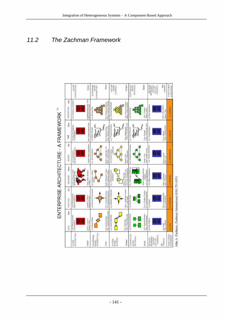
Integration of Heterogeneous Systems – A Component-Based Approach
- 141 -
11.2 The Zachman Framework

Integration of Heterogeneous Systems – A Component-Based Approach
- 142 -
12 References
12.1 Books
Benjamin, M., Vasudevan, B., Villalba, T., & Vogel, A. (1999). C++ Programming withCORBA. New York: Wiley Computer Publishing.
Britton, C. (2000). IT Architectures and Middleware. New Jersey: Addison-Wesley.
Brown, A. W. (1996). Component-based Software Engineering : selected papers from theSoftware Engineering Institute. Washington : IEEE Computer Society.
Gamma, E., Helm, R., Johnson, R., & Vlissides, J. (1995). Design Patterns – Elements ofReusable Object-Oriented Software. Addison-Wesley.
Holström, S. (1990). Konstruktion och verifiering av imperativa program med Dijkstras metod.Institutionen för Datavetenskap, Göteborg Universitet.
Jia, X. (2000). Object-Oriented Software Development Using Java. USA: Addison-Wesley.
Johnson, R., Kast, F., & Rosenzweig, J. (1973). The Theory and Management of Systems. McGraw-Hill
Lewis, P. (1994). Information-Systems Development. Pitman Publishing.
Lundahl, U. & Skärvad, P-H., 1982. Utredningsmetodik för samhällsvetare och ekonomer. Lund:Studentlitteratur.
Magoulas, T., & Pessi, K. (1998). Strategisk IT-management. Department of Informatics,Göteborgs University.
Mathiassen, L., Munk-Madsen, A., Nielsen, P., Stage, J. (1998). Objektorienterad analys och design.Lund: Studentlitteratur
Norrbom, C. (1973). Systemteori – en introduktion. M&B Fackbokförlaget.
Patel, R. & Davidson, B., 1991. Forskningsmetodikens grunder – Att planera, genomföra ochrapportera en undersökning. Lund: Studentlitteratur.
Roman, E. (1999). Mastering Enterprise JavaBeans. New York: John Wiley & Sons.
Ruh, W. A., Maginnis F. X. & Brown, W. J. (2001). Enterprise Application Integration. New York:John Wiley & Sons.

Integration of Heterogeneous Systems – A Component-Based Approach
- 143 -
Schneider, J. & Arora, R. (1997). Using Enterprise Java. Indianapolis, IN: Que Corporation.
Sommerville, I., (1998). Software Engineering. Essex: Addison-Wesley.
Szyperski, C. (1999). Component Software – Beyond Object-Oriented Programming. New York:ACM Press Books.
Wallén, G. (1993). Vetenskapsteori och forskningsmetodik. Lund: Studentlitteratur.
12.2 Web references
Appelbaum, R., Claudio, L., Cline, M., Girou, M., & Watson, J. (1999). The CORBA FAQ –Frequently Asked Questions [WWW document]. URL http://www.aurora-tech.com/corba-faq/index.html
BEA Systems. (2000). BEA WebLogic Enterprise 5.1 [WWW document] URLhttp://edocs.bea.com/wle/interm/corba.htm
Beveridge, T., & Perks, C. (2000). Messaging is the Medium [WWW document]. URLhttp://www.intelligenteai.com/feature/2000929.shtml
Buschmann, F., Meunier, R. Rohnert, H., Sommerlad, P., & Stal, M. (1996). The PatternAbstracts [WWW document]. URL http://hillside.net//patterns/Siemens/abstracts.html
Brooke, C., Pharoah, A., Siegel, J. (2000). Creating Commercial Components – CORBAComponent Model (CCM) [WWW document] URLhttp://componentsource.com/build/corbawhitepaper.asp
Brown, A. W. & Wallnau, K. C. (2000). An Examination of the Current State of CBSE[WWW document] URL http://www.sei.cmu.edu/cbs/icse98/summary.html
Carnegie Mellon, Software Engineering Institute (2000). Component-Based Software Development /COTS Integration [WWW document]. URL http://www.sei.cmu.edu/str/descriptions/cbsd.html
Carnegie Mellon, Software Engineering Institute (2001). How Do You Define Software Architecture?[WWW dokument]. URL http://www.sei.cmu.edu/architecture/definitions.html
Chappell, D. (1997). The Next Wave, Component Software Enters The Mainstream [WWWdocument]. URL http://www.rational.com/products/whitepapers/354.jsp
Christiansson, B. & Jakobsson, L. (2000). Component-Based Software Development Life Cycles[WWW document]. URL http://www.idt.mdh.se/kurser/phd/CBSE/
Dr. Dobbs Journal (1997). The Component Object Model: Technical Overview [WWWdocument]. URL http://www.cs.umd.edu/~pugh/com/
Integration of Heterogeneous Systems – A Component-Based Approach
- 144 -
Eriksson, D. (2000). COM [WWW document]. URLhttp://www.calpoly.edu/~jeriksso/COM/COM_Paper.htm
Eskelin, P. (1999). Component Interaction Patterns [WWW document]. URLhttp://jerry.cs.uiuc.edu/~plop/plop99/proceedings/Eskelin1/ComponentInteractionPatterns.pdf
Gopalan, S. (1998). Microsoft Message Queue Server [WWW document]. URLhttp://www.execpc.com/~gopalan/mts/msmq.html
Gopalan, S. (1999). Middleware Component Models - CCM, EJB, MTS [WWW document]. URLhttp://www.execpc.com/~gopalan/
Griss, M. (2000). My Agent Will Call Your Agent [WWW document]. URLhttp://www.sdmagazine.com/articles/2000/0002/0002c/0002c.htm
Henning, M. (1998). Binding, Migration, and Scalability in CORBA [WWW document] URLhttp://www.ooc.com.au/staff/michi/cacm.pdf
Higham, T. (2001). The Reality of EJB [WWW document]. URLhttp://advisor.com/Articles.nsf/aid/HIGHT11
Hnich, B., Jonsson, T., & Kiziltan, Z. (1999). On the Definition of Concepts in Component BasedSoftware Development [WWW document]. URLhttp://www.idt.mdh.se/kurser/phd/CBSE/reports/Final_reports/report_03.pdf
Hypertext Webster Dictionary. (2001). [WWW document] URLhttp://www.fin.gov.nt.ca/webster.htm
Inprise. (2001). VisiBroker – The Engine for Internet Applications [WWW document] URLhttp://www.inprise.com/visibroker
Institute for Telecommunication Science, (1996). Glossary of Telecommunication Terms [WWWdocument]. URL http://www.its.bldrdoc.gov/fs-1037/
IONA. (2001). Orbix 2000 [WWW document]. URLhttp://www.iona.ie/products/orbix2000_home.htm
Isazadeh, A., MacEwen, G.H. & Malton (1995). A. A Review of Post-Factum SoftwareIntegration Methods [WWW document]. URL http://citeseer.nj.nec.com/1567.html
Jennings, N. (2001). An Agent-Based Approach For Building Complex Software Systems [WWWdocument]. URL http://www.ecs.soton.ac.uk/~nrj/download-files/cacm01.pdf
Jennings, N., & Wooldridge, M. (1995). Intelligent Agents: Theory and Practice [WWWdocument]. URL http://www.ecs.soton.ac.uk/~nrj/download-files/KE-REVIEW-95.ps
JGuru (1999). Enterprise JavaBeans Fundamental [WWW document]. URLhttp://developer.java.sun.com/developer/onlineTraining/EJBIntro/EJBIntro.html

Integration of Heterogeneous Systems – A Component-Based Approach
- 145 -
Johnson, M. (1997). A walking tour of JavaBeans [WWW document]. URLhttp://www.javaworld.com/javaworld/jw-08-1997/jw-08-beans.html
Kiziltan, Z, Jonsson, T. & Brahim, H. (2000). On the Definition of Concepts in ComponentBased Software Development [WWW document] URL http://www.idt.mdh.se/kurser/phd/CBSE/
Kutsche, R-D., & Sünbül, A. (1999). A Meta-Data Based Development Strategy forHeterogeneous Distributed Information Systems [WWW document]. URLhttp://www.computer.org/proceedings/meta/1999/papers/60/rkutsche.html
Larsson, M. (2000). The Different Aspects of Component Based Systems [WWW document].URL http://www.idt.mdh.se/kurser/phd/CBSE/
Larsson, T. & Sandberg, M. (2000). Building Flexible Components Based on Design Patterns[WWW document]. URL http://www.idt.mdh.se/kurser/phd/CBSE/
Levine, D., Schmidt, D., & Wang, N. (2000). Optimizing the CORBA Component Model forHigh-performance and Real-time Applications [WWW-document]. URLhttp://www.cs.wustl.edu/~schmidt/PDF/middleware2000.pdf
Linthicum, D. (1998). Message Broker Rising [WWW document] URLhttp://www.dbmsmag.com/9809d07.html
Linthicum, D. (1999). Mastering Message Brokers [WWW document]. URLhttp://www.sdmagazine.com/articles/1999/9906/9906c/9906c.htm
Linthicum, D. (n.d./2001a) How To Free Your Information – Selecting A Message Broker – Part1 [WWW document]. URL http://eai.ebizq.net/enterprise_integration/linthicum_8.html
Linthicum, D. (n.d./2001b). How To Free Your Information – Selecting A Message Broker – Part2 [WWW document]. URL http://eai.ebizq.net/enterprise_integration/linthicum_9.html
Lycos (2001). The Lycos Tech Glossary [WWW document]. URLhttp://webopedia.lycos.com/Communications/
Mahmoud, Q. (2001, January). Overview of CORBA [WWW document]. URLhttp://developer.java.sun.com/developer/Books/corba/ch11.pdf
Merriam-Webster. (2001). Merriam-Webster Online [WWW document]. URL http://www.m-w.com/
Microsoft (1999). Transaction Server—Transactional Component Services [WWW document].URL http://www.microsoft.com/com/wpaper/revguide.asp
Newmarch, J. (2000, February). Jan Newmarch’s Guide to JINI Technologies [WWWdocument]. URL http://www.javacoffeebreak.com/books/extracts/jini/jini.html
North, K. (1997). Understanding OLE [WWW document]. URLhttp://www.dbmsmag.com/9506d13.html

Integration of Heterogeneous Systems – A Component-Based Approach
- 146 -
Object Management Group. (1997, January). A Discussion of the Object ManagementArchitecture [WWW document]. URL ftp://ftp.omg.org/pub/docs/formal/00-06-41.pdf
Object Management Group. (1998, May). Joint Revised Submission - CORBA/Firewall Security[WWW document]. URL ftp://ftp.omg.org/pub/docs/orbos/98-05-04.pdf
Object Management Group. (1999, March). CORBA Components – Joint Revised Submission[WWW document]. URL ftp://ftp.omg.org/pub/docs/orbos/99-02-05.pdf
Object Management Group. (1999, August). CORBA Component Scripting [WWW document]URL ftp://ftp.omg.org/pub/docs/orbos/99-08-01.pdf
Object Management Group. (1999, October). CORBA 3.0 New Components Chapters [WWWdocument] URL ftp://ftp.omg.org/pub/docs/ptc/99-10-04.pdf
Object Management Group. (2000a, January). Internationalization, Time Operations, andRelated Facilities [WWW document] URL ftp://ftp.omg.org/pub/docs/formal/00-01-01.pdf
Object Management Group. (2000b, January). Mobile Agent Facility Specification [WWWdocument] URL ftp://ftp.omg.org/pub/docs/formal/00-01-02.pdf
Object Management Group. (2001, February). The Common Object Request Broker:Architecture and Specification 2.4.2 [WWW document]. URLftp://ftp.omg.org/pub/docs/formal/01-02-01.pdf
OpenLoop. (2000a). Architectural Patterns: Broker [WWW document]. URLhttp://www.edatamirror.com/openloop/softwareEngineering/patterns/architecturePattern/arch_Broker.htm
OpenLoop. (2000b). Architectural Patterns: Layer [WWW document]. URLhttp://www.edatamirror.com/openloop/softwareEngineering/patterns/architecturePattern/arch_Layers.htm
Orchard, D. (1998). Enterprise Java Beans [WWW document]. URLhttp://www.pacificspirit.com/Authoring/ObjectMag-Ejb/EJB.html
O’Ryan, C., Scmidt, D., & Wang, N. (2000). Overview of the CORBA Component Model[WWW document]. URL http://www.cs.wustl.edu/~schmidt/PDF/CBSE.pdf
Platt, D. (1999). What The Heck Is COM+, Anyway? [WWW document]. URLhttp://www.byte.com/column/BYT19990826S0030
Schmidt, D., & Vinoski, S. (1997). Object Interconnections – Object Adapters: Concepts andTerminology [WWW document]. URL http://www.iona.com/hyplan/vinoski/col11.pdf
Sousa, J.P. & Garlan, D. (1999). Formal Modelling of The Enterprise JavaBeans ComponentIntegration Framework, [WWW document].URL http://reports-archive.adm.cs.cmu.edu/anon/2000/CMU-CS-00-162.pdf

Integration of Heterogeneous Systems – A Component-Based Approach
- 147 -
Sun Microsystems. (2000a). Enterprise JavaBeans, Frequently Asked Questions [WWWdocument]. URL http://java.sun.com/products/ejb/faq.html
Sun Microsystems. (2000b). Jini Architecture Specification Version 1.1 [WWW document].URL http://www.sun.com/jini/specs/jini1.1html/jini-title.html
Sun Microsystems. (2001). Jini Network Technology FAQs [WWW document]. URLhttp://www.sun.com/jini/faqs/
Szyperski, C. (2000). ObjectiveView- Issue 5 : Components versus Objects [WWW document]URL http://www.ratio.co.uk/ov5.pdf
Vinoski, S. (1997, February). CORBA: Integrating Diverse Applications Within DistributedHeterogeneous Environments [WWW document]. URLhttp://www.iona.com/hyplan/vinoski/ieee.pdf
Vinoski, S. (1998, October). New Features for CORBA 3.0 [WWW document]. URLhttp://www.iona.com/hyplan/vinoski/cacm.pdf
Yee, A. (1999). Agent Adapters: Beyond APIs [WWW document]. URLhttp://www.sdmagazine.com/articles/1999/9911/9911b/9911b.htm