Integration of Feature Templates in Product Structures ... · other designers. Manuscript received...
9
Abstract—In today’s product development, the use of templates to reuse knowledge and existing design solutions is well-established. Most CAD systems offer functions for defining and storing design knowledge, but user-friendly classification and structuring is still a matter of research. As a consequence, the retrieval of existing templates is challenging and instead of reusing design knowledge in successive development projects, new design solutions have to be created. In this paper an approach to structure Feature Templates is introduced. The approach is based on the generic product structure, which provides extensive contextual information about possible applications of templates. By integrating structural information about Feature Templates into the product structure, reuse of existing design knowledge can be improved. The approach is exemplarily applied to the assembly of a planetary gear and an elastomer coupling. Index Terms—feature, knowledge based engineering, product family, product structure, template I. INTRODUCTION HE usage of templates to reuse knowledge and design solutions is a common knowledge based engineering (KBE) approach within today’s product development. Most modern CAD systems provide functions to define Feature Templates (FT) and to store and manage them in libraries. In this context, FT represent a creation logic for defining geometry models. The creation logic is depending on parameters, which can be changed by the designer to create different instances of FT. While defining FT is becoming more and more popular, the consequent reuse is still rare due to two main reasons: The first reason is that geometry definition of FT is insufficient to be instantiated in a different context. The second and more frequent reason is that structuring of FT and their libraries are lacking a methodical approach and thus FT cannot be retrieved by other designers. Manuscript received July 10, 2013; revised July 20, 2013. A. Christ is with Technische Universität Darmstadt, Department of Computer Integrated Design, Darmstadt, Hesse, Germany (phone: +49-6151-16-3771; fax: +49-6151-16-6854; e-mail: [email protected] darmstadt.de). V. Wenzel is with Technische Universität Darmstadt, Department of Computer Integrated Design, Darmstadt, Hesse, Germany (e-mail: [email protected]). A. Faath is with Technische Universität Darmstadt, Darmstadt, Hesse, Germany (e-mail: [email protected]). R. Anderl is with Technische Universität Darmstadt, Department of Computer Integrated Design, Darmstadt, Hesse, Germany (e-mail: [email protected]). In this paper a methodical approach to support the structuring process of FT is introduced. The approach combines the product structure, hierarchically representing assemblies and parts of a product or a product family, with the FT library structure as it exists in modern CAD systems. The main goal of the approach is to provide a structuring guideline for FT, which enables linking FT and product structure and which can be comprehended equally well by designers defining FT and designers using them. The usage of FT is most promising in adaptive design, where mainly geometrical details or shape-defining parameters are varied, while the product structure remains basically unchanged. This invariance of the product structure and its comprehensibility for all involved designers supports the integration of FT. Both elements together, the product structure and the FT library structure, define a matrix that allows representing a) relations between different parts of the product structure, b) relations between different Feature Templates, and c) relations between parts and Feature Templates. The capabilities of the approach are illustrated by an example of the product family “planetary gears”, which contains several FT highlighting the different types of relations a), b) and c). The paper shows how the usage of existing and already digitalized knowledge can be enhanced by following a methodical approach for structuring FT. The conceptual approach is independent of any software. But both product structures and FT libraries are accessible in CAD/PDM software and pave the way for a sample implementation. II. RELATED WORK The approach described in this paper belongs to the field of knowledge-based engineering (KBE). Its main goal is the integration of Features Templates in product structures via a proper mapping. This enables the consistent reuse of Feature Templates and established design solutions, but also the integration of expert knowledge through Feature Templates. In this chapter a brief overview about relevant subjects will be given and the essential terms will be defined. A. Product Structure The product structure is a structured presentation of a product. It describes the sub-elements of a product and their Integration of Feature Templates in Product Structures Improves Knowledge Reuse Alexander Christ, Volkmar Wenzel, Andreas Faath, and Reiner Anderl T Proceedings of the World Congress on Engineering and Computer Science 2013 Vol II WCECS 2013, 23-25 October, 2013, San Francisco, USA ISBN: 978-988-19253-1-2 ISSN: 2078-0958 (Print); ISSN: 2078-0966 (Online) WCECS 2013
Transcript of Integration of Feature Templates in Product Structures ... · other designers. Manuscript received...
Abstract—In today’s product development, the use of
templates to reuse knowledge and existing design solutions is
well-established. Most CAD systems offer functions for defining
and storing design knowledge, but user-friendly classification
and structuring is still a matter of research. As a consequence,
the retrieval of existing templates is challenging and instead of
reusing design knowledge in successive development projects,
new design solutions have to be created. In this paper an
approach to structure Feature Templates is introduced. The
approach is based on the generic product structure, which
provides extensive contextual information about possible
applications of templates. By integrating structural information
about Feature Templates into the product structure, reuse of
existing design knowledge can be improved. The approach is
exemplarily applied to the assembly of a planetary gear and an
elastomer coupling.
Index Terms—feature, knowledge based engineering,
product family, product structure, template
I. INTRODUCTION
HE usage of templates to reuse knowledge and design
solutions is a common knowledge based engineering
(KBE) approach within today’s product development. Most
modern CAD systems provide functions to define Feature
Templates (FT) and to store and manage them in libraries. In
this context, FT represent a creation logic for defining
geometry models. The creation logic is depending on
parameters, which can be changed by the designer to create
different instances of FT. While defining FT is becoming
more and more popular, the consequent reuse is still rare due
to two main reasons: The first reason is that geometry
definition of FT is insufficient to be instantiated in a
different context. The second and more frequent reason is
that structuring of FT and their libraries are lacking a
methodical approach and thus FT cannot be retrieved by
other designers.
Manuscript received July 10, 2013; revised July 20, 2013.
A. Christ is with Technische Universität Darmstadt, Department of
Computer Integrated Design, Darmstadt, Hesse, Germany (phone:
+49-6151-16-3771; fax: +49-6151-16-6854; e-mail: [email protected]
darmstadt.de).
V. Wenzel is with Technische Universität Darmstadt, Department of
Computer Integrated Design, Darmstadt, Hesse, Germany (e-mail:
A. Faath is with Technische Universität Darmstadt, Darmstadt, Hesse,
Germany (e-mail: [email protected]).
R. Anderl is with Technische Universität Darmstadt, Department of
Computer Integrated Design, Darmstadt, Hesse, Germany (e-mail:
In this paper a methodical approach to support the
structuring process of FT is introduced. The approach
combines the product structure, hierarchically representing
assemblies and parts of a product or a product family, with
the FT library structure as it exists in modern CAD systems.
The main goal of the approach is to provide a structuring
guideline for FT, which enables linking FT and product
structure and which can be comprehended equally well by
designers defining FT and designers using them. The usage
of FT is most promising in adaptive design, where mainly
geometrical details or shape-defining parameters are varied,
while the product structure remains basically unchanged.
This invariance of the product structure and its
comprehensibility for all involved designers supports the
integration of FT. Both elements together, the product
structure and the FT library structure, define a matrix that
allows representing
a) relations between different parts of the product
structure,
b) relations between different Feature Templates, and
c) relations between parts and Feature Templates.
The capabilities of the approach are illustrated by an
example of the product family “planetary gears”, which
contains several FT highlighting the different types of
relations a), b) and c).
The paper shows how the usage of existing and already
digitalized knowledge can be enhanced by following a
methodical approach for structuring FT. The conceptual
approach is independent of any software. But both product
structures and FT libraries are accessible in CAD/PDM
software and pave the way for a sample implementation.
II. RELATED WORK
The approach described in this paper belongs to the field
of knowledge-based engineering (KBE). Its main goal is the
integration of Features Templates in product structures via a
proper mapping. This enables the consistent reuse of Feature
Templates and established design solutions, but also the
integration of expert knowledge through Feature Templates.
In this chapter a brief overview about relevant subjects will
be given and the essential terms will be defined.
A. Product Structure
The product structure is a structured presentation of a
product. It describes the sub-elements of a product and their
Integration of Feature Templates in Product
Structures Improves Knowledge Reuse
Alexander Christ, Volkmar Wenzel, Andreas Faath, and Reiner Anderl
T
Proceedings of the World Congress on Engineering and Computer Science 2013 Vol II WCECS 2013, 23-25 October, 2013, San Francisco, USA
ISBN: 978-988-19253-1-2 ISSN: 2078-0958 (Print); ISSN: 2078-0966 (Online)
WCECS 2013
interdependencies in a structured composition. The
assignment of elements is realized by product characteristics
and interfaces [1].
In professional literature there exist a wide range of
definitions for the term product structure and it is often used
as a hypernym. Tichem and Storm define product structure
as “a context-dependent description of the composition of
the product out of elements and relations between the
elements.”[2] Wu and Kimura call the realization of product
function the main objective of designing a product structure
[3]. According to Salonen different views on the product
structured have to be taken in consideration [4]. Product
structures are used in several areas, for example as
functional structure, relational model or assembly hierarchy.
They can also be transformed into other forms, like a bill of
material or serve as reference in variant management [2],
[5], [6].
There are several approaches to represent product
structures, usually with the help of pedigrees. Common
structures are simple string, hierarchic order and network.
Based on graph theory the structure consists of nodes. The
topmost node has only outputs and is called root. Inner
nodes contain inputs and outputs. Nodes that only contain
inputs are called leaves [7], [8]. A schematic structure with
the chosen naming convention is shown in Fig. 1.
Fig. 1. Node naming convention [7], [8]
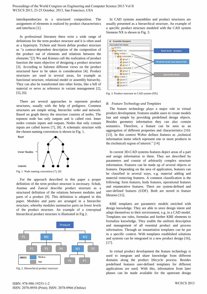
For the approach described in this paper a proper
definition of the term product structure is necessary. Schuh,
Assmus and Zancul describe product structure as a
structured definition of the relations between modules and
parts of a product [9]. This definition is adopted in this
paper. Modules and parts are arranged in a hierarchic
structure, whereby modules summarize parts on lower levels
of the product structure. An example of a conceptual
hierarchical product structure is illustrated in Fig 2.
Fig. 2. Hierarchical product structure
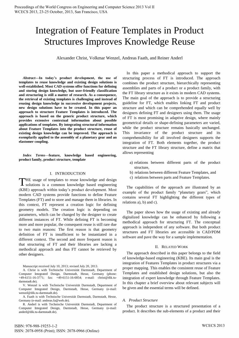
In CAD systems assemblies and product structures are
usually presented as a hierarchical structure. An example of
a specific product structure modeled with the CAD system
Siemens NX is shown in Fig. 3.
Fig. 3. Product structure in CAD system (NX)
B. Feature Technology and Templates
The feature technology plays a major role in virtual
product development. Features enable users to create models
fast and simple by providing predefined design objects.
Besides geometry information they can also contain
semantics. Therefore, a feature can be seen as an
aggregation of different properties and characteristics [10]-
[13]. In this context Weber defines features as „technical
information items which represent one or more products in
the (technical) region of interest.” [14]
In current 3D-CAD systems features depict areas of a part
and assign information to them. They are described by
parameters and consist of arbitrarily complex structure
information. Features can be made up of several objects or
features. Depending on the area of application, features can
be classified in several ways, e.g. material adding and
material removing features. A common classification is the
following: form features, body features, operational features
and enumerative features. There are system-defined and
user-defined features (UDF). Both are stored in feature
libraries [15].
KBE templates are parametric models enriched with
design knowledge. They are able to store design intent and
adapt themselves to their environment, e.g. in a CAD model.
Templates use rules, formulas and further KBE elements to
formalize knowledge. They enable the uniform description
and management of all essential product and process
information. Through an instantiation templates can be put
in a specific context. With templates established solutions
and systems can be integrated in a new product design [16],
[17].
In virtual product development the feature technology is
used to integrate and share knowledge from different
domains along the product lifecycle process. Besides
predefined features user-defined templates for different
applications are used. With this, information from later
phases can be made available for the upstream design
Proceedings of the World Congress on Engineering and Computer Science 2013 Vol II WCECS 2013, 23-25 October, 2013, San Francisco, USA
ISBN: 978-988-19253-1-2 ISSN: 2078-0958 (Print); ISSN: 2078-0966 (Online)
WCECS 2013

process. This allows the reuse of expert knowledge and the
integration of downstream process chains. Benefits are a
shorter time to market, cost reduction and a continuous
enhancement of the design maturity. Both, features and
templates are well-established in industry and science today.
Reusable Feature Templates are approved knowledge based
engineering approaches [11], [16].
C. Feature Templates
Nowadays, features are often used in the form of Feature
Templates. These templates are made up of predefined CAD
features and stored as new Feature Templates with an
immutable structure and changeable parameters. They are
also referred to as user-defined features (UDF). Feature
Templates are an aggregation of attributes and constraints,
enriched with engineering knowledge, to specify the overall
shape. With Feature Templates reusable geometry elements
from below the component level to complex geometric
elements consisting of multiple parts can be defined. Since
Feature Templates can be created in every established CAD
system, they offer a convenient design environment [18],
[19].
Feature Templates are mostly deployed as reusable parts in
variant and adaptive design. They are templates for
application-specific features. Through a well-formed
definition of parameters and constraints they can adapt
themselves intelligently. With this, FT can be treated like
system-defined features. For the integration in several
models a suitable definition of references and interfaces is
needed. Only geometry elements and parameters function as
inputs. FT enable a reliable product development based on
standardization and modularization below the part level and
the integration of expert knowledge from different domains.
They are suitable for modifications, maintenance and
reusability. The consistent application of KBE technologies
reduces the design effort and leads to cost savings [11], [20],
[21].
D. Knowledge Based Engineering
Knowledge Based Engineering enables the consistent
reuse of design solutions and sharing of expert knowledge.
KBE objectives are to save time and to reduce cost in
product development by automating repetitive design tasks.
Therefore KBE systems capture and store knowledge from
different domains about products and processes. This expert
knowledge can then be reused to solve design problems [22],
[23]. Verhagen et al. give a good overview about existing
methodologies and systems [23]. MOKA [24], [25],
KNOMAD [26] and KOMPRESSA [27] are common
representatives.
Although a lot of research has been done towards KBE in
the last decades, there is still a need to develop systems that
support designers with expert knowledge from different
domains of the product life cycle. Chandrasegaran et al.
reflect the importance of knowledge representation in design
systems. They also address reasons for the low acceptance of
knowledge-based systems. Current KBE systems fall short to
integrate knowledge properly. Often the knowledge is only
captured partially and is not represented in a formalized
manner. The appropriate storage in knowledge repositories
is also a yet unsolved problem [28].
Szykman et al. mention the need for supporting the
capture, reuse and formal representation of expert
knowledge. This requires mechanisms to encode, index and
retrieve knowledge. Current KBE systems are often to
complex, have a bad usability and show gaps in their
representation ability. They usually work only in a specific
IT environment, while international and cross-company
product development is usually performed in a
heterogeneous software tool environment [29]-[31].
These shortcomings prevent the comprehensive spreading
and application of knowledge-based systems. Many
individual and customized solutions have been developed,
but they only focus on specific business cases or work only
for a single enterprise. Until now there couldn’t be
established a general methodology. To solve this problem
more research effort has to be applied. Partial improvements
are always possible and they pave the way for a holistic
solution. One improvement is the mapping of Feature
Templates to parts of the product structure. Expert
knowledge is associated to Feature Templates and they can
be stored suitably in a knowledge repository, e.g. a product
lifecycle management (PLM) system [32].
III. CONCEPT
In today’s product development not just particular
products are designed, but mostly product families with
different versions and variants of the same product. They are
characterized by similar shape, functionality and very often
share the same generic product structure. Within such a
product family, the usage of FT enables the harmonized
storage, administration and, most important, the reuse of
existing knowledge and design solutions. In modern CAD
systems FT can be stored and managed in libraries, offering
insufficient functions for classifying FT and for backtracking
instances of used FT. Thus, existing FT and possible
application parts cannot be found easily and instead of using
existing FT, new variants and design solutions are created.
To enhance the knowledge reuse, an approach for a
structured classification and managing of FT is introduced
here.
Although the feature technology and Feature Templates
are common KBE approaches and well-established in
science and industry today, there is still a lack of experience
and knowledge concerning the systematic reuse of Feature
Templates. For designers it is important to know which
Feature Template is used in which Part and how they interact
with each other. The main challenges are the proper
definition of appropriate feature structures, as features are
often stored unstructured in feature libraries, and a suitable
assignment to existing product structures.
Proceedings of the World Congress on Engineering and Computer Science 2013 Vol II WCECS 2013, 23-25 October, 2013, San Francisco, USA
ISBN: 978-988-19253-1-2 ISSN: 2078-0958 (Print); ISSN: 2078-0966 (Online)
WCECS 2013

In research there already exist approaches to define
relationships between features and parts of a product
structure. Shah and Rogers have developed a concept for
feature-based assembly modeling [33], [34]. A framework
for assembly design that enables the creation and
management of several design alternatives as well as the
integration of knowledge has been introduced by Jounghyun
and Szykman [35]. He, Song and Wang use a feature-based
structure concept model to combine parts and components
into a generalized assembly, which can be seen as an
abstraction of the product structure [36]. A lot of other
concepts have been developed for integrating features in
assembly resp. product structures. Although many
approaches are promising, no general concept or method
could become prevalent so far.
Ontologies are one way to represent and reuse knowledge.
Knowledge can easily be integrated in ontologies, but for
complex structures they tend to confusion and it can be
difficult to extract knowledge. For our approach a
specialized graphical user interface would be required. An
interim solution could be provided by ontology editors, like
Protégé [37], but in the long run a specialized software tool
has to be developed [38], [39]. Hence, ontologies should not
be used for our approach.
A. Requirements
Based on the need for a solution that integrates Feature
Templates, and with this knowledge, in product structures
requirements have to be defined. The following
requirements represent the most important ones for the
concept.
Requirement 1
The concept shall enable a simple integration of Feature
Templates in different product structures.
Requirement 2
The procedure of integrating Feature Templates shall be
independent from the respective product structure and shall
be able to be done intuitively.
Requirement 3
An integration of hierarchic product structures is intended.
Requirement 4
The concept shall be based on product family-dependent
product structures.
Requirement 5
Variant and adaptive design are the main scope. It has to be
ensured that the concept is not merely limited to existing
products.
Requirement 6
The concept shall enable the reuse of Feature Templates in
different products as much as possible.
Requirement 7
To reduce complexity parts and Feature Templates should
occur as few as possible.
Requirement 8
The structure of the concept should be chart- or matrix-
based.
Requirement 9
Dependencies between parts of a product and Feature
Templates have to be visualized.
Requirement 10
The concept should have a good and intuitive usability.
Therefore it is necessary to ensure clarity and unambiguity.
Requirement 11
The concept should be independent of a specific software.
These requirements serve as criteria for the evaluation of
the concept. Therefore, the concept will be checked against
the requirements and their fulfillment will be estimated.
B. Conceptual Approach
The approach is based on the generic product structure of
a product. This structure contains different hierarchical
levels and several FT, which can be applied to products of
the product family. A generic product structure represents
the structure of an entire product family and shows, which
types or classes of modules and parts are used in products of
a product family. The opposite of the generic product
structure is the precise product structure, which shows the
particular modules and parts which together form a
particular product. While elements in the precise product
structure refer to the specific instance of a part or module,
elements in the generic product structure refer to the type of
module or part that is used in every product of the product
family. Fig. 4 provides an overview about the difference
between precise and generic product structures.
Fig. 4. Precise and generic product structure
The purpose of a template is to enable reuse of design
solutions and knowledge in developments that are
characterized by similar requirements. The multiple
instantiation of the same template among variants of a
product family offers a high potential for rationalization.
Proceedings of the World Congress on Engineering and Computer Science 2013 Vol II WCECS 2013, 23-25 October, 2013, San Francisco, USA
ISBN: 978-988-19253-1-2 ISSN: 2078-0958 (Print); ISSN: 2078-0966 (Online)
WCECS 2013
The precise product structure only offers information
about one particular product and the use of templates within.
The generic product structure instead offers information
about possible applications of existing templates within a
broad range of similar products. In the following will be
explained, how generic product structure and FT can be used
to create a structure that allows comprehending which FT
can be applied as instances to which parts of the product
family.
The concept follows a matrix based approach. The
previously introduced generic product structure and the list
of existing FT are merged to form a matrix table, which is
called Part-Template-Matrix (PTM). On the horizontal axis,
elements of the generic product structure are outlined. Each
element of the product structure on the lowest hierarchical
level is assigned to a particular column. This ensures that all
relations between FT and parts can be represented, but no
relations between FT and non-geometric elements, e.g.
modules or subassemblies. On the vertical axis, each existing
FT applicable to the related generic product structure is
assigned to a particular line of the matrix. This list can be
derived from the list of FT as it is structured in the library of
the CAD system. Although it is not necessary for the
introduction of this concept, this list should be sorted, e.g.
according to the FT classification, in order to achieve a
proper usability.
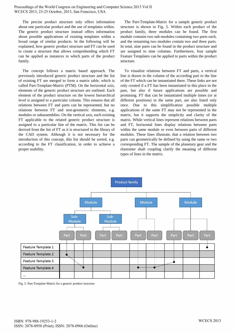
The Part-Template-Matrix for a sample generic product
structure is shown in Fig. 5. Within each product of the
product family, three modules can be found. The first
module contains two sub-modules containing two parts each,
and the remaining two modules contain two and three parts.
In total, nine parts can be found in the product structure and
are assigned to nine columns. Furthermore, four sample
Feature Templates can be applied to parts within the product
structure.
To visualize relations between FT and parts, a vertical
line is drawn in the column of the according part to the line
of the FT which can be instantiated there. These links are not
only created if a FT has been instantiated in this place in the
past, but also if future applications are possible and
promising. FT that can be instantiated multiple times (or at
different positions) in the same part, are also listed only
once. Due to this simplification possible multiple
applications of the same FT may not be represented in the
matrix, but it supports the simplicity and clarity of the
matrix. While vertical lines represent relations between parts
and FT, horizontal lines display relations between parts
within the same module or even between parts of different
modules. These lines illustrate, that a relation between two
parts can geometrically be defined by using the same or two
corresponding FT. The sample of the planetary gear and the
elastomer shaft coupling clarify the meaning of different
types of lines in the matrix.
Fig. 5. Part-Template-Matrix for a generic product structure
Proceedings of the World Congress on Engineering and Computer Science 2013 Vol II WCECS 2013, 23-25 October, 2013, San Francisco, USA
ISBN: 978-988-19253-1-2 ISSN: 2078-0958 (Print); ISSN: 2078-0966 (Online)
WCECS 2013
IV. SAMPLE APPLICATION
The approach has been prototypically implemented with a
sample of a planetary gear and an elastomer shaft coupling,
see Fig. 6. Before the sample implementation of the concept
will be explained, a short overview of the sample assembly
is given. All geometry models have been created with
Siemens NX 7.5.
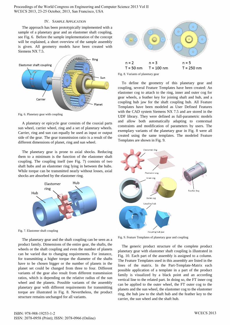
Fig. 6. Planetary gear with coupling
A planetary or epicycle gear consists of the coaxial parts
sun wheel, carrier wheel, ring and a set of planetary wheels.
Carrier, ring and sun can equally be used as input or output
side of the gear. The gear transmission ratio is a result of the
different dimensions of planet, ring and sun wheel.
The planetary gear is prone to axial shocks. Reducing
them to a minimum is the function of the elastomer shaft
coupling. The coupling itself (see Fig. 7) consists of two
shaft hubs and an elastomer ring lying in between the hubs.
While torque can be transmitted nearly without losses, axial
shocks are absorbed by the elastomer ring.
Fig. 7. Elastomer shaft coupling
The planetary gear and the shaft coupling can be seen as a
product family. Dimensions of the entire gear, the shafts, the
wheels or the shaft coupling and even the number of planets
can be varied due to changing requirements. For instance,
for transmitting a higher torque the diameter of the shafts
have to be chosen bigger or the number of planets in the
planet set could be changed from three to four. Different
variants of the gear also result from different transmission
ratios, which is depending on the relative radius of the sun
wheel and the planets. Possible variants of the assembly
planetary gear with different requirements for transmitting
torque are illustrated in Fig. 8. Nevertheless, the product
structure remains unchanged for all variants.
Fig. 8. Variants of planetary gear
To define the geometry of this planetary gear and
coupling, several Feature Templates have been created: An
elastomer cog to attach to the ring, inner and outer cog for
gear wheels, a feather key for joining shaft and hub, and a
coupling hub jaw for the shaft coupling hub. All Feature
Templates have been modeled as User Defined Features
with the CAD system Siemens NX 7.5 and are stored in the
UDF library. They were defined as full-parametric models
and allow both automatically adapting to contextual
constraints and modification of parameters by users. The
exemplary variants of the planetary gear in Fig. 8 were all
created using the same templates. The modeled Feature
Templates are shown in Fig. 9.
Fig. 9. Feature Templates of planetary gear and coupling
The generic product structure of the complete product
planetary gear with elastomer shaft coupling is illustrated in
Fig. 10. Each part of the assembly is assigned to a column.
The Feature Templates used in this assembly are listed in the
lines of the matrix. In the Part-Template-Matrix each
possible application of a template in a part of the product
family is visualized by a black point and an according
vertical line to the related part. In doing so, the FT inner cog
can be applied to the outer wheel, the FT outer cog to the
planets and the sun wheel, the elastomer cog to the elastomer
ring, the hub jaw to the shaft hub and the feather key to the
carrier, the sun wheel and the shaft hub.
Proceedings of the World Congress on Engineering and Computer Science 2013 Vol II WCECS 2013, 23-25 October, 2013, San Francisco, USA
ISBN: 978-988-19253-1-2 ISSN: 2078-0958 (Print); ISSN: 2078-0966 (Online)
WCECS 2013
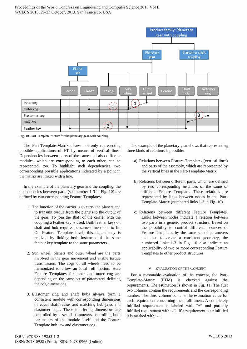
Fig. 10. Part-Template-Matrix for the planetary gear with coupling
The Part-Template-Matrix allows not only representing
possible applications of FT by means of vertical lines.
Dependencies between parts of the same and also different
modules, which are corresponding to each other, can be
represented, too. To highlight such dependencies, two
corresponding possible applications indicated by a point in
the matrix are linked with a line.
In the example of the planetary gear and the coupling, the
dependencies between parts (see number 1-3 in Fig. 10) are
defined by two corresponding Feature Templates:
1. The function of the carrier is to carry the planets and
to transmit torque from the planets to the output of
the gear. To join the shaft of the carrier with the
coupling a feather key is used. Both feather keys on
shaft and hub require the same dimensions to fit.
On Feature Template level, this dependency is
realized by linking both instances of the same
feather key template to the same parameters.
2. Sun wheel, planets and outer wheel are the parts
involved in the gear movement and enable torque
transmission. The cogs of all wheels need to be
harmonized to allow an ideal roll motion. Here
Feature Templates for inner and outer cog are
depending on the same set of parameters defining
the cog dimensions.
3. Elastomer ring and shaft hubs always form a
consistent module with corresponding dimensions
of equal shaft radius and matching hub jaws and
elastomer cogs. These interfering dimensions are
controlled by a set of parameters controlling both
parameters of the module itself and the Feature
Template hub jaw and elastomer cog.
The example of the planetary gear shows that representing
three kinds of relations is possible:
a) Relations between Feature Templates (vertical lines)
and parts of the assembly, which are represented by
the vertical lines in the Part-Template-Matrix.
b) Relations between different parts, which are defined
by two corresponding instances of the same or
different Feature Template. These relations are
represented by links between nodes in the Part-
Template-Matrix (numbered links 1-3 in Fig. 10).
c) Relations between different Feature Templates.
Links between nodes indicate a relation between
two parts in a generic product structure. Based on
the possibility to control different instances of
Feature Templates by the same set of parameters
and thus to create a consistent geometry, the
numbered links 1-3 in Fig. 10 also indicate an
applicability of two or more corresponding Feature
Templates to other product structures.
V. EVALUATION OF THE CONCEPT
For a reasonable evaluation of the concept, the Part-
Template-Matrix (PTM) is checked against the
requirements. The estimation is shown in Fig. 11. The first
two columns contain the requirements and the corresponding
number. The third column contains the estimation value for
each requirement concerning their fulfillment. A completely
fulfilled requirement is labeled with “+” and partially
fulfilled requirement with “o”. If a requirement is unfulfilled
it is marked with “-“.
Proceedings of the World Congress on Engineering and Computer Science 2013 Vol II WCECS 2013, 23-25 October, 2013, San Francisco, USA
ISBN: 978-988-19253-1-2 ISSN: 2078-0958 (Print); ISSN: 2078-0966 (Online)
WCECS 2013
TABLE I
REQUIREMENTS AND THEIR FULFILLMENT
No. Requirement Fulfillment
1 Simple Integration of Feature
Templates +
2 Intuitive procedure o
3 Integration of hierarchic product
structures +
4 Based on product family-dependent
product structures +
5 Not limited to existing products +
6 Enable the reuse of FT in different
products +
7 No multiple occurrence of parts and
FT -
8 Chart- or matrix-based structure +
9 Visualization of dependencies +
10 Good and intuitive usability o
11 Independence of a specific software +
The Part-Template-Matrix enables the simple integration
of Feature Templates, due to the matrix-based structure. It is
applicable to different product structures, but for each
product one matrix is needed. The assignment of Feature
Templates to parts is a relative easy task for product
designers. Capturing all dependencies between Feature
Templates used in a product is a serious challenge even for
design experts. Therefore, the procedure of creating a
specific Part-Template-Matrix is not always as intuitive as
desired.
As the Part-Template-Matrix enables the reuse of Feature
Templates in different products, it can efficiently be applied
in variant and adaptive design. It is used for existing and
new products as well as for whole product families. One of
the main advantages of the Part-Template-Matrix is the
visualization of affiliations and dependencies between parts
and Feature Templates. Feature Templates get instantiated
by an entry in the matrix where the respective Feature
Template and part intersect. Dependencies between different
Feature Templates are visualized by lines. Through the
integration of hierarchic product structures relations between
parts and modules of a product are represented.
Although the visualization of dependencies is a main
advantage of the Part-Template-Matrix, clarity and
unambiguity are limited for highly complex product
structures. Through the integration of hierarchic product
structures parts normally occur multiple times. All Feature
Templates only appear once. As mentioned above, the
difficulty of creating a PTM depends on the complexity of
the product structure and the number of relations.
Nevertheless, a prepared Part-Template-Matrix gives
engineers a quick and suitable overview combined with a
good and intuitive usability. The Part-Template-Matrix is
independent from a specific software. The application is
independent from specific program skills and license fees.
VI. CONCLUSION AND OUTLOOK
Benefit of the Part-Template-Matrix is a structured
visualization of dependencies and affiliations between
Feature Templates, parts and modules of a product. Most of
all the PTM gives a proper overview, which Feature
Template is used in which part and of the relations between
Feature Templates. PTM enables a clear assignment of
features resp. Feature Templates to single parts of the
product structure. This simplifies the reuse of expert
knowledge, which is stored in the Feature Templates.
The Part-Template-Matrix provides a reasonable design
aid, since a matching between existing geometry and
required Feature Templates can easily and quickly be
visualized. Fast access to Feature Templates saves time and
their reuse leads to a constant quality in the design process.
Dead files are avoided, as the availability of a Feature
Template is captured and processed in a defined product
context. Through the consistent use of Feature Templates
variant reduction and an establishment of geometry
standards can be achieved.
The applicability of the PTM concept is demonstrated by
the use of a planetary gear and an elastomer shaft coupling.
The sample application shows that the clarity of the chosen
matrix-based approach is sometimes limited, if the product
structure is highly complex and the same Feature Templates
are used in several parts. To provide a remedy, a decrease of
the product structure’s complexity is conceivable, e.g.
through a modularization of the product.
Future research will concentrate on the development of
methods and tools for a further integration of Feature
Templates. The development of a feature structure similar to
product structure is intended as well as the assignment of
both structures. The generation of a feature structure would
require an appropriate classification of Feature Templates.
Another research issue is the multi-usage of Feature
Templates in a single part. Therefore, the Part-Template-
Matrix has to be enhanced. The application of a number
scheme and a color code are conceivable. The integration of
KBE methods and tools into a Product Data Management
(PDM) system allows the reuse of established design
solutions. Nevertheless, it can be difficult to get the relevant
information for feature based modeling out of the PDM
system [32]. The central storage of Feature Templates would
improve the knowledge capturing. Therefore, the
prototypical linkage of the Part-Template-Matrix to a PDM
system is planned.
REFERENCES
[1] VDI 2209, “3D product modelling. Technical and organizational
requirements,” Procedures, tools, and applications. Cost-effective
practical use. Berlin. Beuth Verlag, 2009.
[2] M. Tichem and T. Storm, “Designer support for product structuring -
development of a DFX tool within the design coordination
framework,” Computers in Industry, Volume 33, Issues 2-3, 1997 pp.
155-163.
[3] Y. Wu, and F. Kimura, “Conceptual design of product structure for
parts reuse,” Advances in Life Cycle Engineering for Sustainable
Manufacturing Businesses. Proceedings of the 14th CIRP Conference
on Life Cycle Engineering, Tokyo, Japan, 2007, pp. 35-40.
Proceedings of the World Congress on Engineering and Computer Science 2013 Vol II WCECS 2013, 23-25 October, 2013, San Francisco, USA
ISBN: 978-988-19253-1-2 ISSN: 2078-0958 (Print); ISSN: 2078-0966 (Online)
WCECS 2013

[4] N. V. Salonen, “Dynamic product structure configuration of
superimposed part structure solutions,” International Journal on
Interactive Design and Manufacturing (IJIDeM), Volume 1, Issue 4,
2007, pp. 185-194.
[5] B. Agard and S. Bassetto, “Modular design of product families for
quality and cost,” International Journal of Production Research, Vol.
51, No. 6, 2013, pp. 1648-1667.
[6] E. Nurcahya, “Configuration instead of new design using reference
product structures,” The Future of Product Development. Proceedings
of the 17th CIRP Design Conference, F. L. Krause, ed., 2007, pp.
125-134.
[7] L. Ibarra, “A fully dynamic graph algorithm for recognizing interval
graphs,” WALCOM, Algorithms and Computation. Third
International Workshop, S. Das, and R. Uehara, eds., Kolkata, India,
2007, pp. 190-201.
[8] S. Nakano, R. Uehara and T. Uno, “A new approach to graph
recognition and applications to Distance-Hereditary graphs,” Journal
of Computer Science and Technology, Volume 24, Issue 3, 2009, pp.
517-533.
[9] G. Schuh, D. Assmus and E. Zancul, “Product structuring - the core
discipline of product lifecycle management,” 13th CIRP International
Conference on Life Cycle Engineering, 2006.
[10] K. Case and M. S. Hounsell, “Feature modelling. A validation
methodology and its evaluation,” Journal of Materials Processing
Technology, Volume 107, Issues 1-3, 2000, pp. 15-23.
[11] VDI 2218, “Information technology in product development. Feature
Technology,“ Berlin. Beuth Verlag, 2012.
[12] X. Chen and C. M. Hoffmann, “On editability of feature-based
design,” Computer-Aided Design, Volume 27, No. 12, 1995, pp. 905-
914.
[13] D. C. Anderson and T. C. Chang, “Geometric reasoning in feature
based design and process planning,” Computer Graphics, 14(2),
1990, pp. 225-235.
[14] C. Weber, “What is a feature and what is its use? - Results of
FEMEX Working Group I,” 29th International Symposium on
Automotive Technology and Automation 1996 (ISATA 96),
Florence/Italy, pp. 109-116.
[15] R. Anderl, “New information technologies in industrial activity of the
enterprises (IAE),” Manufacturing Technologies for Machines of the
Future. 21st Century Technologies, Part III, A. Dashchenko, 2003,
pp. 461-513.
[16] A. Katzenbach, W. Bergholz and A. Rolinger, “Knowledge-based
design - An integrated approach,” The Future of Product
Development. Proceedings of the 17th CIRP Design Conference, F.
L. Krause, ed., 2007, pp. 13-22.
[17] O. Kuhn, T. Dusch, P. Ghodus and P. Collet, “Framework for the
support of knowledge-based engineering template update,”
Computers in Industry, Volume 63, Issue 5, 2012, pp. 423-432.
[18] C. M. Hoffmann and R. J. Joan-Arinyo, “On user-defined features,”
Computer-Aided Design, Vol. 30, No. 5, 1998, pp. 321-332.
[19] V. Wenzel, A. Christ, J. T. Jagenberg, D. Strang, R. Anderl and T.
Bornkessel, “Functional shape elements integrating design and
manufacturing knowledge,” Smart Product Engineering. Proceedings
of the 23rd CIRP Design Conference, M. Abramovici, and R. Stark,
eds., Bochum, Germany, 2013, pp. 969-978.
[20] R. Bidarra, and W. F. Bronsvoort, “Semantic feature modelling,”
Computer-Aided Design, Volume 32, Issue 3, 2000, pp. 201-225.
[21] R. Xiao, Y. Zu and S. Mei, “Creative product configuration design
driven by functional features,” Journal of Manufacturing Systems,
Volume 31, Issue 1, 2012, pp. 69-75.
[22] D. Cooper and G. LaRocca, “Knowledge-based techniques for
developing engineering applications in the 21st Century,”
Proceedings of the 7th AIAA Aviation Technology, Integration, and
Operations Conference (ATIO), Belfast, 2007.
[23] W. J. C. Verhagen, P. Bermell-Garcia, R. E. C. van Dijk and R.
Curran, “A critical review of knowledge-based engineering: An
identification of research challenges,” Advanced Engineering
Informatics, Volume 26, Issue 1, 2011, pp. 5-15.
[24] K. Oldham, S. Kneebone, M. Callot, A. Murton and R. Brimble,
“MOKA - A Methodology and tools Oriented to Knowledge-based
engineering Applications,” Shaping the ICT-solutions for the Next
Century, 1998, pp. 198-207.
[25] P. Sainter, K. Oldham, A. Larkin, A. Murton and R. Brimble,
“Product knowledge management within knowledge-based
engineering systems,” Proceedings of the ASME 2000 Design
Engineering Technical Conference (DETC), Baltimore.
[26] R. Curran, W. J. C. Verhagen, M. J. L. van Tooren and T. H. van der
Laan, „A multidisciplinary methodology for knowledge based
engineering: KNOMAD,” Expert Systems with Applications, Volume
37, Issue 11, 2010, pp. 7336-7350.
[27] P. Lovett and C. Bancroft, “Knowledge transfer for knowledge based
engineering,” Proceedings of Technology Transfer and Innovation
Conference (TTI), London, 2000.
[28] S. K. Chandrasegaran, K. Ramani, R. D. Sriram, I. Horvath, A.
Bernard, R. F. Harik and W. Gao, “The evolution, challenges, and
future of knowledge representation in product design systems,”
Computer-Aided Design, Volume 45, Issue 2, 2013 pp. 204-228.
[29] S. Szykman, R. D. Sriram and W. C. Regli, „The role of knowledge
in next-generation product development systems,” Journal of
Computing and Information Science in Engineering, Volume 1,
Issue 1, 2001, pp. 3-11.
[30] S. Szykman, “Architecture and implementation of a design repository
system,” Proceedings of DETC2002, DETC2002/CIE-34463,
Montreal, Canada.
[31] B. Bettig and V. Bapat, “Integrating multiple information
representations in a single CAD/CAM/CAE environment,”
Engineering with Computers, Volume 22, Issue 1, 2006, pp. 11-23.
[32] D. Pugliese, G. Colombo and M. S. Spurio, “About the integration
between KBE and PLM,” Advances in Life Cycle Engineering for
Sustainable Manufacturing Business, Proceedings of the 14th CIRP
Conference on Life Cycle Engineering, Tokyo, 2007, pp. 131-136.
[33] J. J. Shah and M. T. Rogers, “Assembly modeling as an extension of
feature-based design,” Research in Engineering Design, Volume 5,
Issue 3-4, 1993, pp. 218-237.
[34] J. J. Shah, “Assessment of feature technology,” Computer-Aided
Design, Volume 23, No. 5, 1991, pp. 331-343.
[35] G. Jounghyun and S. Szykman, “Combining interactive exploration
and optimization for assembly design,” Proceedings of the 1996
ASME Design Engineering Technical Conference and Computers in
Engineering Conference, Irvine, California, Paper no. 96-
DETC/DAC-1482.
[36] B. He, W. Song, Y. Wang, “A feature-based approach towards an
integrated product model in intelligent design,” The International
Journal of Advanced Manufacturing Technology, 2013.
[37] Stanford Center for Biomedical Informatics Research, The Protégé
Project, 2013, http://protege.stanford.edu/.
[38] V.-C. Liang, C. J. J. Paredis, “A port ontology for conceptual design
of systems,” Journal of Computing and Information Science in
Engineering, Volume 4, Issue 3, 2004, pp. 206-217.
[39] T. R. Gruber, “Toward principles for the design of ontologies used for
knowledge sharing,” International Journal of Human-Computer
Studies, Volume 43, Issue 5-6, 1995, pp. 907-928.
Proceedings of the World Congress on Engineering and Computer Science 2013 Vol II WCECS 2013, 23-25 October, 2013, San Francisco, USA
ISBN: 978-988-19253-1-2 ISSN: 2078-0958 (Print); ISSN: 2078-0966 (Online)
WCECS 2013