
Integration of computational design tools in the design ...
240
Integration of computational design tools in the design and production of prefabricated homes A thesis submitted to fulfil requirements for the degree of Doctor of Philosophy Robert Doe (BSc Architecture (Hons), Diploma Architecture, Master of Studies) Innovation in Applied Design Lab, Faculty of Architecture, Design and Planning, The University of Sydney Date: 12/06/2018
Transcript of Integration of computational design tools in the design ...
Integration of computational design tools in the design and production of prefabricated homes
A thesis submitted to fulfil requirements for the degree of Doctor of Philosophy
Robert Doe (BSc Architecture (Hons), Diploma Architecture, Master of Studies)
Innovation in Applied Design Lab,
Faculty of Architecture, Design and Planning,
The University of Sydney
Date: 12/06/2018


This is to certify that, to the best of my knowledge, the content of this
thesis is my own work. This thesis has not been submitted for any
degree or other purposes.
I certify that the intellectual content of this thesis is the product of
my own work and that all the assistance received in preparing this
thesis and sources have been acknowledged.
Student’s name: Robert Doe
Signature:

This thesis contains material published in Papers 1 to 3. I designed the
study and was primary author of these papers:
Chapter 6 contains material from Paper 1, ‘Multi-criteria
optimisation in the design of modular homes - from theory to
practice’, in Real Time - Proceedings of the 33rd Annual Conference
of Education Research in Computer Aided Design in Europe
(eCAADe15), 2015
Chapter 7 contains material from Paper 2, ‘Facilitating change: the
design domain in prefabricated home design’, in Proceedings of
Parallelism in Architecture, Environment and Computing
Techniques (PACT), 2016, and also from Paper 3, ‘Facilitating change:
the modular format in the design of prefabricated homes’, in
Proceedings of the 50th International Conference of the Architectural
Science Association (ASA), 2016
As supervisor for the candidature upon which this thesis is based, I
can confirm that the authorship attribution statements above are
correct.
Supervisor’s name: Professor Mathew Aitchison
Signature: Date: 8 December 2017
This research makes the case that integrated computational
design tools, combined with better strategies for
prefabrication, can exploit synergies to improve the quality of
homes in Australia.
This should be of significant interest to educators and
architects progressively challenged by implementation of
these new tools, by questions of design authorship and by the
desire to take concepts to realisation seamlessly. These
complex uncertainties prompt an additional aim of this study
- to orient architectural discourse, in education and practice,
towards demands for better, more effective design tools
focussed on the integrated making of projects through a
streamlined process that links all participants.
The case for integration is reinforced by a methodology
directed towards:
• Exposing the complementarity of computational design
tools integrated with prefabricated home assembly
through literature review and case study precedents, in
Australia and internationally.
• Demonstrating, through the implementation of three live
projects aligned to funded research streams, that
computational design tools are synergetic with
prefabrication utilising modular design methods, and
that integration of these tools and methods leads to
better quality homes. The methodology includes
reporting the findings of this research utilising Herbert
Simon’s ‘science of design’ (Simon 1996, p. 111) and Donald
Schön’s ‘reflection-in-action’ (Schön 2008, p. 85).
• Proposing an Integrated Modelling approach to assist
with identification of the intensity of integration of
computational design and production methods and tools,
to provide a brief for the toolmakers, and to support
improvements to integration of the architectural,
engineering and construction (AEC) sector’s operations
and systems.
This research aims to make an original contribution to better
understanding of the symbiosis between computational
design tools and the design and making of prefabricated
homes. It is a relationship which promotes credible and
realisable outcomes because it embraces the constraints
imposed by the logic of design and production processes as
they exist today.
Abstract

My thanks to Professor Mathew Aitchison and Dr Rizal Muslimin for
their inspiration and support, and to my PhD colleagues at the
Innovation in Applied Design Lab, The University of Sydney. Also, my
thanks to Happy Haus, Hutchinson Builders, BVN Donovan Hill and
Kate Humphries (University of Queensland).
This dissertation is dedicated to my partner Venessa Lam and
daughter Beatrice Doe, and to my family and friends, near and far in
time and space.
• advanced CAD, manufacturing sector CAD, feature-
based modelling, or solid modelling e.g. Digital
Project (Gehry Technologies/Trimble), 3D
Experience & SolidWorks (Dassault), NX (Siemens)
• AEC CAD, Architecture, Engineering and
Construction (AEC) sector Computer-Aided Design
(CAD) software e.g. Revit (Autodesk), Archicad
(Graphisoft), MicroStation (Bentley)
• assembly, is the fitting together, on or off-site, of
parts and components
• associative programming, or visual programming
graphs, use the concept of graph dependencies to
establish 'flow control’ e.g. Grasshopper, Dynamo
(Autodesk)
• authorship, is the fact of being the sole creator of the
architectural design and its built form
• Building Information Modelling (BIM), is a
process for creating and managing all project
information embodied in AEC CAD 3D models
• closed system refers analogously to living organisms
which allow no inflow or outflow of materials
• collaboration refers to AEC participants working
together to meet their goals
• computational design is an exploratory process
with the goals of rationalisation, reasoning and logical
outcomes. No specific CAD tools
• conceptual design is an initial stage of the
architectural design process
• construction is the work of building or making
something, usually on a building site
• conventional design is the process of drafting,
creating and managing project information (BIM),
visualisation and form finding. No specific CAD tools
• declarative format design rules explain the facts and
rules of a situation; this encompasses optimisation
problems which combine theories of probability and
utility e.g. PROLOG, LISP, shape grammars
• detailed design is an intermediate stage of the
architectural design process
• design domain is a framework of topological
relationships representing design intent
• design intent, the expression of conceptual ideas
• fabrication is conflated from ‘digital fabrication’
where the making of products or components result
directly from computational design processes
• federated models are a collection of shared models
created in AEC CAD during a BIM process
Glossary
• imperative programming, or procedural
programming, is characterised by explicit ‘flow
control’ which describes steps to achieve end results
e.g. C#, Python and DesignScript (Autodesk)
• integration is the process of combining two or more
things into one, or of becoming part of a group
• interaction is conflated from ‘dynamic interaction’
and refers analogously to interactions which occur
within and between organisms’ parts
• interoperability is the facilitation of exchange
without affecting the functioning of a system e.g. the
use of common exchange formats, Industry
Foundation Classes (IFCs), or customised scripts
• modular design refers to principles which reduce
complexity into understandable parts
• modular format design rules encourage openness
and interchangeability between parts
• open system, or openness, refers analogously to
living organisms which allow the inflow and outflow
of material in a state of homeostasis
• operability is the usability, user-friendliness,
reliability and maintainability of the tools used
• optimisation is the search for the best state in a
natural or artificial system
• parametric modelling, or ‘constraint modelling’,
allows parts to relate and change in a coordinated way
• prefabrication is the off-site manufacture of parts,
components and 3D modules for assembly elsewhere
• production is the process and action of making or
manufacturing from parts and components
• protocols are procedures and rules which facilitate
or impair engagement with a tool or method e.g.
‘open-source’, ‘closed-integrated’, and neutral file
exchanges (e.g. IFCs)
• set up is the process which begins definition of the
design intent
• shared model defines a single shared model used by
all participants on advanced CAD projects
• simulation refers to the analysis and testing of
physical and virtual models
• templates are patterns for making analogue or
digital copies of shapes and forms
• topology is the way that the parts of something are
organised or connected
1 Introduction …………………….………… 1
1.1 Outline of thesis 1
1.1.1 Thesis problems 2
1.1.2 Thesis sub-problems 3
1.1.3 Objectives and scope 4
1.1.4 Research contribution and originality 5
1.1.5 Research beneficiaries 5
1.1.6 Research findings and benefits 6
1.2 Computational design 6
1.3 Prefabrication 9
1.4 Methodology 11
1.4.1 Project research methodology 12
1.5 Structure of the thesis 13
1.6 Limitations 17
2 Analogue to digital ……………………. 19
2.1 Control 19
2.2 Proportion and order 23
2.2.1 Case Study 1 – Segal & Frazer 25
2.3 Systems 28
2.3.1 Measure of Integration 31
2.4 Summary 36
3 Generation and set up ………………… 38
3.1 Set up 39
3.2 Interface 41
3.2.1 Alternative AEC interfaces 42
3.2.2 Parametric modelling 43
3.2.3 Declarative format 44
3.3 Interaction 46
3.3.1 Case Study 2 – WikiHouse & Flux 48
3.4 Summary 50
4 Simulation and optimisation ………… 52
4.1 Simulation 53
4.1.1 Simulation of spatial and thermal performance 56
4.1.2 Simulation of the design studio 56
4.1.3 Simulated project workflows 57
4.2 Optimisation 58
4.2.1 Optimisation searches 58
4.2.2 Intuition and computation 59
4.2.3 Optimisation algorithms 60
4.2.4 Multi-criteria optimisation 61
4.2.5 Collaboration and optimisation 61
4.2.6 Case Study 3 – Evins et al. 62
4.3 Summary 64
Contents

5 Prefabrication ………………………… 66
5.1 Coordination 67
5.2 Modular design 70
5.2.1 Case Study 4 - Loblolly House & Bensonwood 73
5.3 Prefabrication 76
5.3.1 Case Study 5 – Stehn & Bergström 77
5.3.2 Case Study 6 – Jensen et al. 78
5.4 Summary 80
6 Project 1: Searching for better ……… 82
6.1 Introduction 82
6.2 Project methodology 83
6.2.1 Multi-criteria optimisation 84
6.3 Findings 86
6.3.1 Single trial GA optimisation 86
6.3.2 Simple GA optimization 100
6.3.3 Micro GA optimisation 106
6.4 Summary 110
7 Project 2: Generation and set up ……. 112
7.1 Introduction 112
7.2 Project methodology 113
7.2.1 Design domain 115
7.2.2 Associative programming and modular formats 115
7.3 Findings 116
7.3.1 Design domain 116
7.3.2 Associative programming 123
7.3.3 Modular format 127
7.4 Summary 135
8 Project 3: A modular design strategy .. 140
8.1 Introduction 140
8.2 Project methodology 142
8.3 Findings 144
8.3.1 Frame 144
8.3.2 Coordination 149
8.3.3 Modular design 156
8.3.4 Realisation 162
8.4 Summary 165
9 Discussion ……………………………... 167
9.1 Searching ‘intelligently’ for better 169
9.1.1 Single trial – an overview 170
9.1.2 Simple GA – thorough but slow 173
9.1.3 Micro GA efficiency 174
9.2 Rigorous and flexible frameworks 177
9.2.1 Whole and partial design domains 177
9.2.2 Associative programming challenges 178
9.2.3 Modular format challenges 180
9.3 A modular design strategy 183
9.3.1 Framing flexibility 183
9.3.2 Closed integration: an incomplete system 185
9.3.3 Modular design strategy 187
9.3.4 Seamless realization 190
9.4 Summary 190
10 Integrated modelling ………………… 192
10.1 Methodology 192
10.1.1 Purpose 192
10.1.2 Operation 193
10.1.3 Limitations 195
10.2 Project 1 - Searching for better 195
10.3 Project 2 - Generation and set up 199
10.4 Project 3 - A modular design strategy 202
10.5 Summary 206
11 Conclusion …………………………....… 207
11.1 How will the integration of 207
computational design tools be achieved?
11.2 How will it improve the design and 208
production of prefabricated homes?
11.3 How will this integration 211
affect architects’ education and practice?
11.4 Summary 213
Bibliography …………………………… 215
Published works 216
Works cited 217
Illustration credits 226

1
Reason, order, prediction and control have played a central part in the systems argument. (Russell 1981, p. 699)
In many ways, the energy of architects through the ages has
been directed towards ensuring that design intentions are
realised in the completed object. In the 1st century BC,
Vitruvius described the architect’s role in shaping this
realisation. During the Renaissance, this notion of the
architect’s role developed into the idea of the architect as the
sole author of design intent, and their separation from the
building process. As noted by Mario Carpo: with Alberti’s
separation in principle between design and making came the
modern definition of the architect as an author, in the
humanistic sense of the term (Carpo 2011, p. X). This concern
with the fidelity of design intent as representative of the
completed building is a narrative that can be traced from the
analogue to the digital age as methods of controlling
outcomes have been refined. However, the digital age of
interaction and cooperation has introduced new methods
and tools. Order and proportion have been freed of the
constraints of orthogonal organisation, and control is no
longer the preserve of the architect.
An understanding that architecture is a systemic whole, not
reducible to its parts, means that new design tools are
assistants in the process of reasoning, and in predicting
holistic design outcomes. Central to this activity, is the
integration of design tools and their assimilation with
production methods. Presaged in earlier times, the tools of
parametric modelling, simulation, algorithmic searching and
automation could today be part of this systemic integration
in the making of architecture. In turn, the making of
architecture could influence the nature of these design tools.
For instance, modularity, the assembly of parts and their
interactions, and the configurability of components, are
concepts common to new computational design tools and to
improved methods of making architectural solutions. This
combination suggests that these concepts have developed
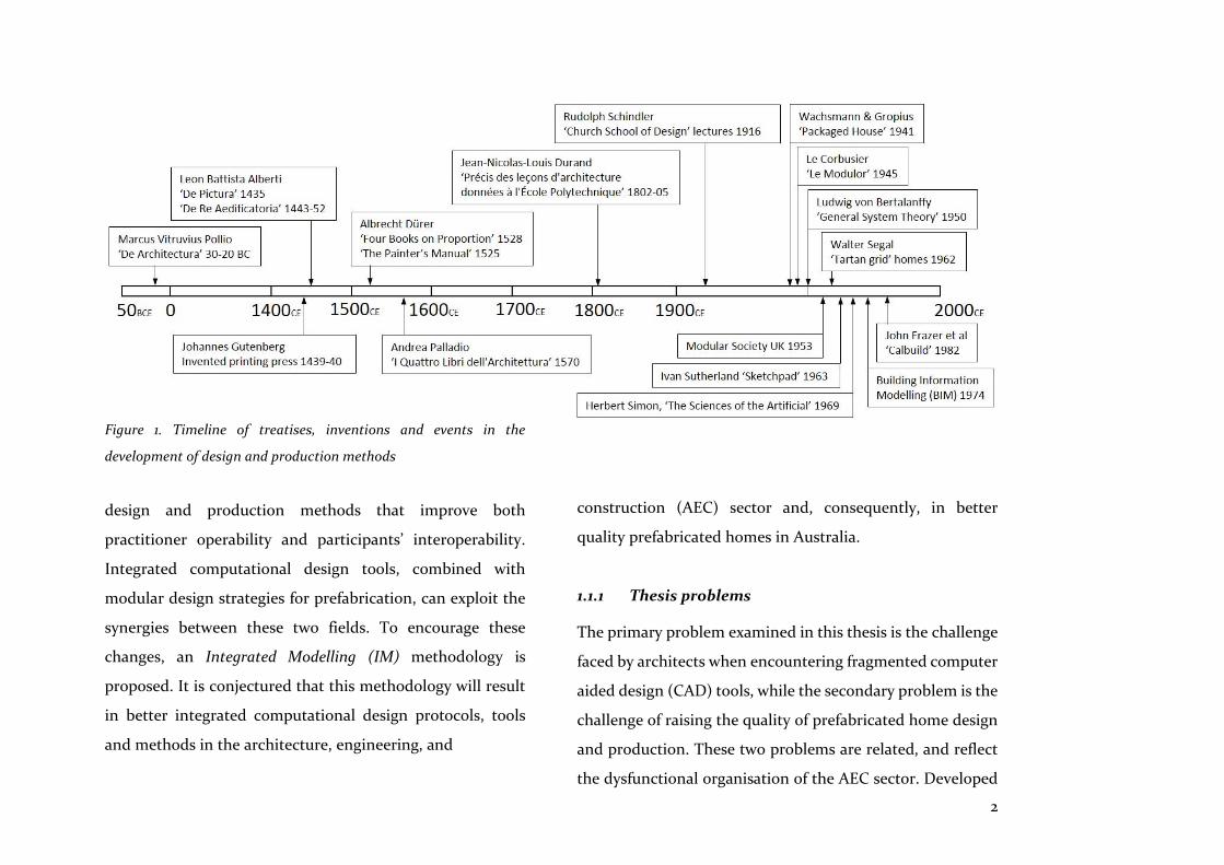
progressively from the analogue to the digital age (Figure 1):
1.1 Outline of the thesis
This research postulates, that integrated computational
design tools combined with compatible prefabrication
techniques will lead to better housing alternatives. It also
maintains that solutions lie in more effective, user-friendly
1 Introduction
2
Figure 1. Timeline of treatises, inventions and events in the
development of design and production methods
design and production methods that improve both
practitioner operability and participants’ interoperability.
Integrated computational design tools, combined with
modular design strategies for prefabrication, can exploit the
synergies between these two fields. To encourage these
changes, an Integrated Modelling (IM) methodology is
proposed. It is conjectured that this methodology will result
in better integrated computational design protocols, tools
and methods in the architecture, engineering, and
construction (AEC) sector and, consequently, in better
quality prefabricated homes in Australia.
1.1.1 Thesis problems
The primary problem examined in this thesis is the challenge
faced by architects when encountering fragmented computer
aided design (CAD) tools, while the secondary problem is the
challenge of raising the quality of prefabricated home design
and production. These two problems are related, and reflect
the dysfunctional organisation of the AEC sector. Developed
3
over the past 60 years, design tools are form-generation and
documentation focused, and thus fail to accommodate the
full complexity of architectural design workflows and tasks.
Often, these design tools are both difficult to use, and
unreliable. They also lack integration with other participants’
design tools (e.g. developers, engineers, contractors,
manufacturers, fabricators), do not facilitate collaboration
with these participants, and are not integrated into the
production and assembly stages. Furthermore, downstream
of the design process, the prefabrication of homes lacks a
strategy for integration with digital design and production
tools. Thus, a strategy that responds to synergies between
these new design tools and their production outcomes is
needed.
Computational design methods and tools that are
differentiated from conventional CAD address some of the
deficiencies noted above; however, they also bring challenges
of their own. For example, when using computational design
tools, the identity of the author of the design solutions
generated is sometimes unclear. This lack of clarity often
deters the engagement of a discipline that is steeped in the
idea of the single author of a design. In short, the early
promise that CAD would be an effective assistant, an
interactive adjunct, and an intelligent aid has not
materialised. These are the technological challenges
architects face when engaging with digital age design tools,
and some of the key issues this research addresses.
1.1.2 Thesis sub-problems
Sub-problems identified in this thesis are the management
challenges that architects and the AEC sector face as the
result of systemic dysfunction and insufficient integration.
Though not the focus of this study, these challenges demand
practice and sector changes. This thesis suggests that such
changes would occur concurrently with, and be motivated by,
the technological changes examined in the following
chapters. For instance, the role of the architect within this
emerging paradigm will need to embrace collaboration and
interaction.
Additionally, the AEC sector will need to improve the
interoperability and effectiveness of exchanges among
participants. Indeed, this has been the focus of initiatives
since Australia’s pioneering Alliance projects in the mid-
1990s (Walker & Hampson 2003). These projects led to

4
Partnering in the United Kingdom (Latham 1994) and, by
2007, to Integrated Project Delivery in the United States (AIA
2007). The technological focus of these initiatives in the AEC
sector has become known as ‘Building Information
Modelling’ (BIM), a concept initiated by Eastman et al. at
Carnegie Mellon University in 1974 (Eastman et al. 1974).
Today, BIM is variously, and often contradictorily, defined as
a process for creating and managing all project information,
or as an intelligent 3D model that improves the efficiency of
planning, designing, constructing and managing buildings.
1.1.3 Objectives and scope
The objectives and the scope of this thesis follow from the
statement of the hypothesis, that integrated computational
design tools combined with compatible prefabrication
techniques will lead to better housing alternatives:
Firstly, the goal of better housing alternatives will only be
achieved when computational design tools become
integrated and can be fully engaged in a seamless process
from conceptual design to production. This requires better
tools that can maintain flexible parametric relationships
between elements of the design intent, but also tools that are
capable of simulating and optimising quantifiable design
objectives, and can even provide ‘intelligent’ assistance to
help architects find better solutions.
Secondly, it is proposed that, to achieve this goal, a guide is
needed to help evaluate and define the meaning of ‘integrated
computational design tools’. Therefore, this study formulates
a Measure of Integration (MoI) for this purpose. The AEC
sector has neglected the essential requirement that their
systems and tools should be integrated to function well and
support the design and production process. Reflection-in-
action during the implementation of project work will inform
this guide, whilst lessons will also be drawn from the
manufacturing sector which has consistently pursued
integration of its design and production tools.
Thirdly, it is proposed that ‘compatible prefabrication
techniques’ embrace modular design because of the intrinsic
synergy between this approach and computational design
thinking. Thus, the making of artefacts and buildings will be
more appropriately aligned to the process of conception and
design.

5
Fourthly, the hypothesis cannot overlook educational and
practitioner awareness of, and engagement with, integrated
computational design tools and processes combined with
improved prefabrication techniques, if it is to result in better
housing alternatives. This engagement needs to be cultivated
in a climate of collaboration and trust amongst all members
of the AEC sector.
1.1.4 Research contribution and originality
This research aims to contribute to a better understanding of
the symbiosis between integrated computational design tools
and better strategies for the construction of prefabricated
homes. This aim is furthered by the proposal of the IM rating
methodology. IM is based on the features and attributes
defined by the MoI (Chapter 2), and by principles that
promote the modular design of prefabricated homes. IM’s
goal is to assess the integration intensity level of
computational design tools and methods that are
implemented in the three projects examined for this study,
and to provide a methodology that is more widely applicable
to other projects, methods, and tools.
The research hypothesis is tested using ‘the science of design’
(Simon 1996, p. 111) and Donald Schön’s ‘reflection-in-action’
methodology (Schön 2008, p. 85) in three live projects that
implement everyday architectural design tasks. This
methodology brings to the surface tacit assumptions about
current design and production methods; these can then be
assessed according to their utility and effectiveness. This
approach facilitated synthesis of the proposal for the IM
rating methodology, centring on integration as the key
measure for assessment.
1.1.5 Research beneficiaries
This research should be of significant interest to educators
and architects who are progressively challenged by the
implementation of new design tools and methods. These
beneficiaries include: those separated by the historical divide
between design and construction, a separation fuelled by
architects’ belief in the notion of ‘sole author’; and
participants brought together by design tools which are
integrated with other participants’ tools, and that are suitable
for the task of taking concepts to detailed design to
production. The implications and effects of improved
integrated design processes, and a methodology to measure
6
the intensity of their integration into AEC workflows—while
at the same time incorporating a modular design
prefabrication strategy—should also be of wider benefit to
the prefabrication sector of the AEC industry in Australia and
internationally.
1.1.6 Research findings and benefits
Findings from each project guided by the MoI reveal that
when integrated computational design tools were utilised,
benefits included more certainty that design intent would be
realised, and greater reassurance that performance objectives
could be met. As noted previously, the MoI forms the basis of
an IM methodology that aims to foster these beneficial
outcomes by providing a measure of the intensity of
integration for these and other projects. This, in turn, leads
to the formulation of solutions that increase this intensity.
The Findings also reveal that an integrated design process is
essential because it provides more certainty that design
intentions will be achieved, that data loss will be reduced,
that the downstream re-working of drawings will be
eliminated, that fewer errors will occur, and that the end
result will concur with participants’ initial expectations. The
historical and recent context that has led to this imperative
for integration in the AEC sector, and for better strategies for
prefabricated home design and production, is now examined
in parallel with the literature review. This examination is then
supported by selected case studies in Chapters 2 to 5.
1.2 Computational design
To continue as architects, we must change our ideas. (Scheer 2014, p. 192)
Computational design has been characterised as being
exploratory in nature; as having the goals of rationalisation,
reasoning, and logical outcomes; and as using the processes
of deduction and induction, and prediction and estimation
(Terzidis 2006, p. 58). As Mark Burry notes, it has also been
differentiated from current CAD practice as involving
‘intentionality’, or ‘…the mapping of an idea through to an
intended outcome’ (Burry, M 2011, p. 25). While
computational design is often contrasted with the CAD
design processes commonly used by architects, many of their
features are often shared or overlap. Since the development
of CAD in the early 1960s, it has been argued that architects
and designers have remained as spectators leaving the
7
technological capabilities of CAD systems to be resolved by
programmers to the extent that, ‘…CAD software developers
are meta designers…’ (Terzidis 2006, p. 54). As a result, CAD
in many architectural practices is mainly used to implement
‘computerisation’, which, as Kostas Terzidis explains, is a
pejorative term: ‘Generally, it involves the digitisation of
entities or processes that are preconceived, predetermined,
and well defined’ (Terzidis 2006, p. 57).
Thus, architectural CAD skills have been limited to drafting
and visualisation, or to form-finding— skills restricted to the
manipulation and storing of preconceived entities in the
computer system’s database. This emphasis has prevented
the development of skills that could also have encompassed
integrated computational design tools capable of taking
conceptual ideas to realisation on-site, and within a
collaborative and holistic design environment. It is also noted
here that the manufacturing sector’s advanced CAD
platforms incorporate many computational design tools;
thus, this research often differentiates between ‘AEC CAD’
and ‘advanced CAD’. Correspondingly, some AEC CAD tools
incorporate computational design capabilities: for example,
this research examines Autodesk Revit’s ability to facilitate
the modelling of prefabricated components by defining
‘Families’ utilising parametrically connected templates.
A challenge to architects’ involvement with, and shaping of,
computational design tools includes their self-perception as
sole authors (as noted earlier), a notion which frustrates
integration because it deters open participation. This
perception is seen both within practice, and in the promotion
of design work to AEC participants. Traditionally, control of
the design tool represented control of the design. Now,
however, as Yannis Loukissas comments, architects are
asking: ‘Who am I in relation to software?’ (Loukissas 2009,
p. 167). Educators have been aware of the need to introduce
computational design skills to architectural students as a key
part of their design craft (McCullough 2006, p. 14). In
particular, these educators have highlighted the need for
tomorrow’s architects to understand how their design
decisions influence the making of forms and objects,
emphasising process over product (Aitchison & Doe 2017;
Burry, J 2007; Hanna & Turner 2006; Schnabel, M A 2012).
In moving forward the debate over authorship, Terzidis has
also suggested that architects should be more open to the
8
question, ‘Who designs?’ (Terzidis 2006, p. 60). Awareness
and acceptance of computational design tools as co-
contributors to the process of design and its outcomes is
required. Perception has to move towards the notion of
collective making, a departure from the current perception of
architecture being designed by one group and made by others
(Carpo 2011, p. 16). In changing their ideas, architects could
learn much from other fields of design, particularly the
manufacturing sector. In that sector, digital design tools are
seen as adjuncts, as partners and advocates in the design
process, rather than simply as novel form-finders or threats
to design authority.
However, problems remain for architects in deciding which
computational design tools are useful for their purposes. For
example, these tools need to be more responsive to a design
process that is typically open-ended, involving changes of
mind and changes of constraints. As Bryan Lawson noted in
his critique of Christopher Alexander’s own self-critical
attempts to test the capabilities of logical design processes,
not all stages of design are amenable to the use of
computational design tools (Lawson, B 2005, p. 76).
Furthermore, intelligibility is key to the uptake of
computational design tools as noted by Jane Burry et al.
(2007; 2012). Correspondingly, Sean Hanna (2010, 2014)
counsels focus on the nuances of uncertainty in creative
design tasks, rather than on the uncertainties of engineering
design tasks, the focus to date. But intelligibility will also be
improved if these tools acquire a degree of intelligence and,
as Yehuda Kalay noted, ‘Embedded intelligence need not be
elaborate to be effective’ (Kalay 2004, p. 196). For example,
such intelligence is part of the bespoke multi-criteria
optimisation tool DEXEN devised by Patrik Janssen et al.
(2011; 2016). Nevertheless, Wassim Jabi et al. (2013) remind us
of the importance of human intuition and good judgement
during the evaluation of optimisation tasks. It is evident,
however, that computational design tools can be challenging
and complex, thus frustrating intelligibility. In addressing
this complexity, Marc Aurel Schnabel (2011; 2012) accentuates
process over product, with development of the notion of an
immersive virtual environment design studio (VeDS) that
fosters greater interactivity and collaboration.
This study focuses on integrated computational design tools
combined with compatible prefabrication techniques. It
9
examines them in the context of everyday architectural
design tasks, and in relation to the challenges presented in
architects’ engagement with them. In so doing, it exposes
their potential, or lack thereof, to improve design outcomes.
1.3 Prefabrication
‘Prefabrication’ refers to the off-site assembly of parts,
components and volumes; it can be compared to processes in
the manufacturing sector, where products are made in the
factory. While prefabrication has a long history in the AEC
sector, architects’ engagement with it has been irregular and
infrequent. In times of great need, such as the post-war era of
labour shortages, examples of successful engagements can be
found. As Barry Russell (1981, p. 243) notes, for example,
clients and tenants of the single-storey ARCON homes in the
UK (late 1940s) were impressed by the quality of this
architecturally designed collaboration with industry. In
general, however, it is argued that architects’ unsuccessful
attempts to deliver prefabricated solutions are due to a lack
of understanding of, and engagement with, industry. Walter
Gropius and Konrad Wachsmann’s ‘Packaged House’ system
is often cited as an example of this failure in the post-war
years in the USA (Davies 2005, p. 23).
A preferred method for architects’ engagement with the AEC
sector has been expressed in an emphasis on dimensionally
coordinated systems. For example, Rudolph Schindler’s
preoccupation with modular coordination in the 1920s and
30s was an early attempt to reintegrate design and
construction. Schindler referred to human proportion when
defining ‘reference frames in space’, the framework for a
system that facilitated integrated spatial and component
design, as recorded in Jin Ho Park’s study of his work (2005a,
p. 69). This preference for an organising whole can be traced
back to Vitruvius’s assertion in the 1st century BC that temple
design should be based on the proportions of the human
body, a conception in which the part is understood within a
hierarchical relationship to the whole (Vitruvius 1960, p. 14).
However, despite the schism between architecture and
construction dating from the Renaissance, architecture, in a
contemporary sense, is a collaborative process which must
include the wider culture of the construction industry to
achieve its goals. And, as already noted, architects’ direct
involvement with the fabrication of homes and their
component parts, whether successful or not, pre-dates
current interest shown in digital methods. Supporting this

10
idea, Ryan Smith et al. (2010, p. 55) propose that integrated
practice should adopt Integrated Project Delivery (IPD) as a
process essential for prefabrication to succeed. Clearly then,
the notion of the architect as sole author of design outcomes
has not only hindered their engagement with computational
design tools, but has also impeded collaboration with
industry attempts to supply prefabricated homes. As we
transition from the age of mass production to the age of mass
customisation (Kieran & Timberlake 2004, p. 111), authorship
shared with customers and manufacturers is an expectation
of the digital age, as is choice and flexibility. Indeed, in the
early 21st century, horizontal integration of design and
production is envisaged as an ‘interactive’ and ‘collaborative’
process in which actors and agents blur into a flat ‘isotropic
platform’ (Carpo 2011, p. 113).
The design process for prefabricated homes varies according
to the nature of markets in different countries. For example,
in Sweden a long tradition of prefabrication has resulted in a
sophisticated combination of customer-focus, good design
and implementation via industrialised platforms (Aitchison
& Doe 2017, p. 122), while in Australia, boutique prefab home
firms utilise in-house or commissioned architects and
utilitarian prefab homes are offered by specialised
contractors with in-house designers. Nevertheless, common
challenges arise during the design of prefabricated homes:
end-user participation (Broome 1986); design tools’
interoperability (flux.io 2017b; WikiHouse 2017a); customer
choice (Stehn & Bergström 2002); the operability and
intelligibility of tools (Jensen, Olofsson & Johnsson 2012);
collaboration between design and production participants
(Wikberg, Olofsson & Ekholm 2014).
It should also be noted that, despite perceptions of
authorship, it is clear that some architects in Australia find
the collaborative process complementary. This speaks to the
mindset of those comfortable with notions of combinatorial
and modular design, rather than to more traditional-minded
architects who might be happy to keep construction site-
based. Hence, this study examines prefabrication’s modular
potential, with off-site examples and their interfaces relevant
to programming and manufacturing paradigms, as described
by Lawson et al. (2014). However, it also notes the nature of
the Australian market, where a shift in cultural expectations
is needed to promote innovative and affordable housing
solutions (Newton et al. 2015, p. 7). With this in mind,
11
inspiration can be drawn from Kieran and Timberlake
architects in the USA who, immersed in the activity of
designing and making buildings collectively and
collaboratively, observe that:
The vision of an integrated process, in which a collective intelligence replaces the architect’s singular imposed intelligence, must become widespread before off-site fabrication can become the standard means of architectural construction. (Kieran & Timberlake 2004, p. 109)
While integration and collaboration might have been
hindered by division among architects and other AEC
participants, architects discernibly want to understand how
to use computers to their full potential, and to collaborate in
making better quality homes by taking assembly off-site. This
goes to the essence of the differentiation (made earlier)
between computerisation and computational design tools.
This research demonstrates that these new design tools and
off-site methods of making homes, in an Australian context,
result in a creative and productive alliance. Architecture
incorporates craft, and this study argues that these new tools
underpin these craft skills—skills that need updating in the
interest of better quality outcomes.
1.4 Methodology
The research methodology is multi-facetted; that is, different
methods are implemented to illuminate its various aspects
(Evans, D, Gruba & Zobel 2011, p. 129). These methods include
the literature review, selected case studies, and project work
aligned with live research case studies that utilise a variety of
computational design tools. More specifically:
• Case studies are chosen to support the literature review
chapters. They examine precedents that are assessed
according to the themes of the research and the particular
chapter concerned.
• Project work is at the core of this research. This is
examined with the methods of ‘the science of design’
(Simon 1996, p. 111) and ‘reflection in action’ (Schön 2008,
p. 85):
1. Projects are chosen based on externally funded
research streams that explore the prefabrication of
homes, and that test the hypothesis that that
integrated computational design tools combined with
compatible prefabrication techniques will lead to
better housing alternatives .
2. A variety of tools are used to facilitate comparison of
findings and to mitigate the ‘trace’ of software, a
12
transmuting phenomenon noted by Carpo (2011, p.
100). The design tools used are categorised by
Schodek et al. (2005, pp. 182-183); however, their
descriptions are amended where noted: ‘concept
modellers’, e.g. Rhinoceros; ‘component based
programs’, e.g. Autodesk Revit; ‘design development
programs’, e.g. CATIA, Digital Project. The
description ‘component based program’ is replaced
with ‘AEC CAD’, while ‘design development program’
is replaced with ‘advanced CAD’: the former are
ubiquitous within the AEC sector, while the latter are
rarely used. Other tools utilised include ‘visual
programming’ software (e.g. Grasshopper, Autodesk
Dynamo) and their plug-ins, and an environmental
‘simulation engine’ (EnergyPlus8.1).
3. The projects and the tools used were evaluated based
on the MoI founded on Ludwig von Bertalanffy’s
(2008) definition of open systems, with their
characteristics of dynamic interaction, operability
and interoperability. The rationale for converging on
these characteristics is defined in detail in Chapter 2.
4. The MoI forms the basis for the IM rating
methodology described in Chapter 10.
The project work is guided by two approaches. Accordingly,
Simon’s positivist view of design as ‘rational problem solving’
(Cross 2006, p. 102) directs searches for optimal solutions in
Chapter 6, Project 1, while permeating this and Projects 2 and
3 in Chapters 7 and 8, is Schön’s notion of ‘reflective practice’,
the constructivist view that we construct knowledge and
meaning from experience. As noted by Kees Dorst, the two
approaches utilised to examine design practice and processes
‘have complementary strengths for gaining an overview of the
whole range of activities in design’ (as cited in Cross 2006, p.
102). Schön’s approach, used here to reflect on tacit norms
behind understanding of integration in the early and
intermediate stages of architectural design, discloses the way
that we frame the problems we are trying to solve, and shows:
… how reflection-in-action may be rigorous in its own right, and links the art of practice in uncertainty and uniqueness to the scientist’s art of research. (Schön 2008p. 85)
The MoI records these approaches by depicting and
describing the qualitative and quantitative experience of
performing the architectural design task while utilising a
particular set of design tools.
13
The strategy employed in this research—to test its main
hypothesis that integrated computational design tools
combined with compatible prefabrication techniques will lead
to better housing alternatives —was to explore precedents
and case studies by a literature review, and to then respond
to gaps in the knowledge through project work. In summary,
the framework followed in this dissertation is engaged with:
• Exposing, through the literature review and case study
precedents in Australia and internationally, the
complementarity of computational design tools and
prefabricated home assembly
• Demonstrating, through the implementation of three live
projects aligned to funded research case studies, that
computational design tools work together with
prefabricated methods of home assembly, and that the
integration of these tools and processes leads to better
quality outcomes
• Reporting the findings using ‘the science of design’
(Simon 1996, p. 111) and ‘reflection-in-action’ research
methods (Schön 2008, p. 85). Findings are captured by
the MoI methodology which measures responses to these
questions.
• Proposing an Integrated Modelling (IM) methodology to
assist with identification of the intensity of integration
inherent in the features and attributes of computational
design and production protocols, methods, and tools. The
goal of the IM methodology is to promote integration of
the AEC CAD sector’s protocols, methods, and tools.
1.5 Structure of the thesis
Chapters 2 to 5
Supported by case studies of precedents, the literature review
in Chapters 2 to 5 examines the integration of traditional and
current design tools, and their relationships with production
processes. It argues that integration has been influenced by
past practices that separated the architect from the builder.
This separation engendered attempts to remotely control
design outcomes, and shaped authorial norms that idealised
the role of individual designer or architect. However,
methods founded in System Theory - methods that subsume
computational design techniques and prefabricated methods
of construction - are reshaping relationships between
designers and producers, and their modes of practice.
14
Chapter 2, Analogue to digital investigates traditional design
and production processes, and the development of methods
to control and order outcomes. System Theory is assessed
and utilised to define the MoI that guides evaluations and
assessment of the projects and their findings.
Case study 1: The Walter Segal method (UK, 1982), and
John Frazer’s digital version of this method - a tangible
user interface (TUI) - are examined.
Chapter 3, Generation and set up examines the set up of
parametrically designed models compared with conventional
and methods. Consideration is given to the graphical user
interface (GUI) and the range of interaction it allows.
Case study 2: WikiHouse’s open digital building system,
and Google’s Flux interoperability software are explored
and assessed.
Chapter 4, Simulation and optimisation examines adjuncts to
searches for better solutions, and the contribution these tools
make to integration.
Case study 3: A multi-criteria optimisation study is the
focus of a low-carbon-dioxide housing problem
(Scotland, UK, 2012).
Chapter 5, Prefabrication examines the nature and
consequences of open integration for prefabrication systems
and computational design tools. It argues that considerations
of coordination and modular design strategies are an
appropriate prefabrication methodology when implemented
synchronously with parametric and automated
computational design tools.
Case study 4: Loblolly House (Maryland, USA, 2006) and
Unity House (Maine, USA, 2007)
Case study 5: Degrees of allowable customer choice and
their effects on downstream production flows (Sweden,
2002)
Case study 6: Modularisation and configuration of a
multi-storey timber building system (Sweden, 2012)
Chapters 6 to 8
The hypothesis - that integrated computational design tools
combined with compatible prefabrication techniques will lead
to better housing alternatives -presages the rationale behind
decisions to use particular computational design tools for the
three projects examined, and determines that these tools
should be relevant to the tasks implemented.

15
Chapters 6 to 8 discuss three projects developed within live
research case studies that test the hypothesis of this thesis
and its relevance in small-scale home prefabrication markets
like Australia’s.
Chapter 6, Project 1 Searching for better. AEC CAD
computational design tools comprise an open, integrated
system. They are used to examine optimisation in the context
of a prefabricated modular home series. This project
examines the strengths and weaknesses of a multi-criteria
optimisation search, and its ability to integrate developed
designs and their prefabricated outcomes.
Chapter 7, Project 2 Generation and set up. The interruption
between concept and design development that occurs when
using computational design tools for set-up, is an
impediment to architects’ engagement. This project
examines this set up process for a three-storey, hybrid,
prefabricated housing project in Brisbane (Queensland,
Australia).
Chapter 8, Project 3 A modular design strategy.
Manufacturing’s advanced CAD tools comprise closed
integrated systems and are used to examine modular design
techniques common to the manufacturing sector.
Component sharing and cut-to-fit modularity are two of the
techniques applied to the design of panellised floor and wall
components, and to the configuration of modular bathroom
pods and clip-on balconies. This project tests the vision of
this research: that the combined effect of integrated
computational design tools working together with
prefabrication methods can lead to significantly improved
outcomes.
Chapter 9: Discussion
The discussion assesses the findings of each project, and is
guided by the MoI that focuses on the features and attributes
of the computational design tools and methods applied.
With Project 1, the genetic algorithm encouraged open
collaboration. This collaboration began with the creative
input of the architect, and then required all participants to
carefully hone the project objectives, to direct meaningful
searches for better solutions. The GA necessitated high
interoperability with the parametric model and the
simulation engine, and required knowledge of algorithmic
and evolutionary search processes. However, the results
16
included many more and better solutions than the architect
could find if acting alone, thus improving the prefabricated
volumetric home solutions provided.
Set up of the design domain in Project 2, included formation
of sub-design domains that established the openness of
relationships between the whole model and its parts. Set up
was implemented using associative programming to improve
ease-of-use and intelligibility. However, scaling-up to
complex tasks over-stretched the capability of this method.
Design rules expressed in a modular format encouraged
openness and interchangeability between parts, while also
revealing compatibilities with building assembly methods.
The hybrid prefabrication strategy of Project 3 was
underpinned by the modular design strategy, and
implemented using an advanced CAD system. This fully
integrated tool combined well with prefabricated methods of
assembly. A single, shared model facilitated interoperability
between participants’ design tasks. Advanced CAD has many
task specific applications within its closed system, therefore
interoperability is fundamental to its functioning effectively.
Data loss was eliminated as no files needed to be exchanged
with other vendors’ applications using this closed integrated
system.
If assimilated with prefabrication techniques and widely-
used, these integrated computational design tools would
significantly impact the practice of architecture, and the
training of architectural students, as discussed in the
concluding chapter.
Chapter 10: Integrated Modelling
This chapter introduces and demonstrates the use of the
Integrated Modelling (IM) methodology that synthesises the
hypothesis of this research. It does this by imagining,
devising, and demonstrating the notion of a fully integrated
modelling system, and the way in which projects might be
appraised to reach improved levels of integration intensity.
Like BIM, IM ranks levels of proficiency from 0-3; however,
where BIM’s general aim is to improve the efficiency of AEC
projects, the IM tool’s aim is quite specific - to provide, by
way of graphic illustration and appraisal, a means for
improving the intensity of integration of computational
design protocols, tools and methods utilised by the AEC
sector.
17
Chapter 11: Conclusion
This conclusion draws on the evidence of the literature
review and its selective case studies; the findings of the
project work (as earlier discussed); the IM tool; and the
modular design strategy to answer the main questions
implied by the hypothesis:
• How will integration of computational design tools be
achieved?
• How will this improve the design and production of
prefabricated homes?
• How will integration affect architects’ education and
practice?
Reflection-in-action has been a significant part of the
research methodology of this study. This approach is
appropriate in a context where the pace of change allows little
time for practice to ‘pause for reflection’. Hence, this study
contributes to this pressing need for reflection, and models
reflective practice in reflecting on the above questions during
the implementation of the study’s project work.
Although the way that architects think might not have
changed significantly, their cognitive flow has been disturbed
by the digital flow of bits, allowing them to achieve more than
they could when acting alone. Thus, full engagement with
these emergent computational design tools will provide more
and better design solutions, and will improve the way that
prefabricated homes are produced. IM, which will
increasingly incorporate smarter and more intelligent means
to advance design objectives, is proposed as an aid to finding
these better solutions.
1.6 Limitations
The limitations of this research are shaped by the objectives
noted in Section 1.1.3 which themselves follow-on from the
stated hypothesis. These limitations include:
• Integration of participant workflows and
communications in the AEC sector, because this would be
an extensive and complex undertaking involving
intersubjective testing of all AEC participants.
• Integration of design and production methods to foster
seamless workflows from concept to realisation, because
this moves beyond the research scope to include
interactions between all AEC participants and across all
design and production stages.
18
• Detailed examination of the influx of digital fabrication
tools and methods (e.g. 3D printing, robotic fabrication),
and their contribution to integrated design workflows
involving user participation, because this moves beyond
the research scope to include interactions between all
AEC participants, across all design and production stages.
Nevertheless, as later discussed in Chapter 2, because
integration is holistic in scope the research includes a
brief examination of the integration of design tools in
partnership with prefabrication methods.
• Integration of technological and management changes. It
is acknowledged that management changes would be
concurrent with technological changes arising from the
emergence of integrated computational design tools and
improved methods of production, but detailed discussion
of management tools and methods is beyond the scope of
this research.
This research is also limited by an approach which excludes
intersubjective corroboration of results, or validation by
questionnaire of the project work. Instead, the findings
examined by the Measure of Integration (MoI) in Chapter 10
are based on qualitative and heuristic values defined by the
researcher. Nevertheless, the project work carried out by the
researcher is analytically and empirically tested and
evaluated.
19
This Chapter examines the hypothesis of this research: it
outlines the features and attributes of integrated
computational design tools combined with compatible
prefabrication techniques which are necessary to achieve
better housing alternatives in the AEC sector. A case study is
also presented: Walter Segal’s analogue prefabricated
housing method of the late 20th century, which attracted the
attention of those exploring transitions to integrated digital
techniques.
2.1 Control
… few great Works are compleated by the first Undertaker… For this Reason I think we should adhere to the original Design of the Inventor, who we are to suppose had maturely weighed and considered it. (Alberti 1755, De Re Aedificatoria, Book 9, Chapter 11)
In the western world, Vitruvius’s De Architectura, written
c.30-20 BC, was a significant source of architectural theory.
As noted earlier, it influenced development of the idea of the
architect as sole author of the design from initial sketch to
completed building, a perception which progressively
sanctioned architects’ separation from the process of making
buildings. This role was formalised by Leon Battista Alberti
in De Re Aedificatoria (written between 1443-52), the first
modern treatise on the theory and practice of architecture,
which Carpo depicts as defining the principles of ‘an
authorial, allographic, notational art’, principles that
computational design tools are only now ‘unmaking’ (Carpo
2011, p. 44).
The Alphabet and the Algorithm (Carpo 2011) has been an
inspiring influence for this study, in particular, Carpo’s
elucidation of the succession from the innovators of the
Renaissance, to today’s computationally design-focussed
architects. In developing this theme, Carpo describes digital
architecture’s current practice of combining designing with
making as counter to the Albertian paradigm, which focused
on design, and separated these activities.
Elaborating on the tools of practice that supported this
authorial approach, in his treatise De Pictura (1435), Alberti
described the laws of perspective and a machine to assist its
capture, a square wooden frame with a ‘veil’ which enabled
the artist to transfer an image onto a piece of paper to
facilitate the drafting of perspective views (Alberti 1755, De
Pictura, Books 1-3). These experiments with representation
occurred prior to the invention of the printing press, and
2 Analogue to Digital

20
underpinned Alberti’s objective to ensure reproducibility
and, as noted by Branko Mitrović, to demonstrate the
quantifiable nature of visual perception:
Alberti’s principle that the totality of human visual experience is quantifiable is the fundamental assumption of architectural practice. This principle makes three-dimensional computer modelling software possible. (Mitrović 2004, p. 319)
The printing press, invented by Johannes Gutenberg in the
mid-15th century, enabled identical copies of designs to be
distributed and, in 1570, Andrea Palladio presented his
theories in I Quattro Libri dell'Architettura (The Four Books
of Architecture). This publication was illustrated with
Alberti’s protocols for set up of architectural project drawings
(Carpo 2011, p. 28). David Ross Scheer affirms that these
protocols preserved models of frontality and symmetry,
using ‘…proportions and angles, with no geometrically
consistent idea of projection’, unlike today’s orthographic
drawings which are mathematically based projections
(Scheer 2014, p. 61). Palladio’s illustrations emphasised the
Renaissance architects’ primary purpose in determining
formal symmetry, while leaving construction to the builder.
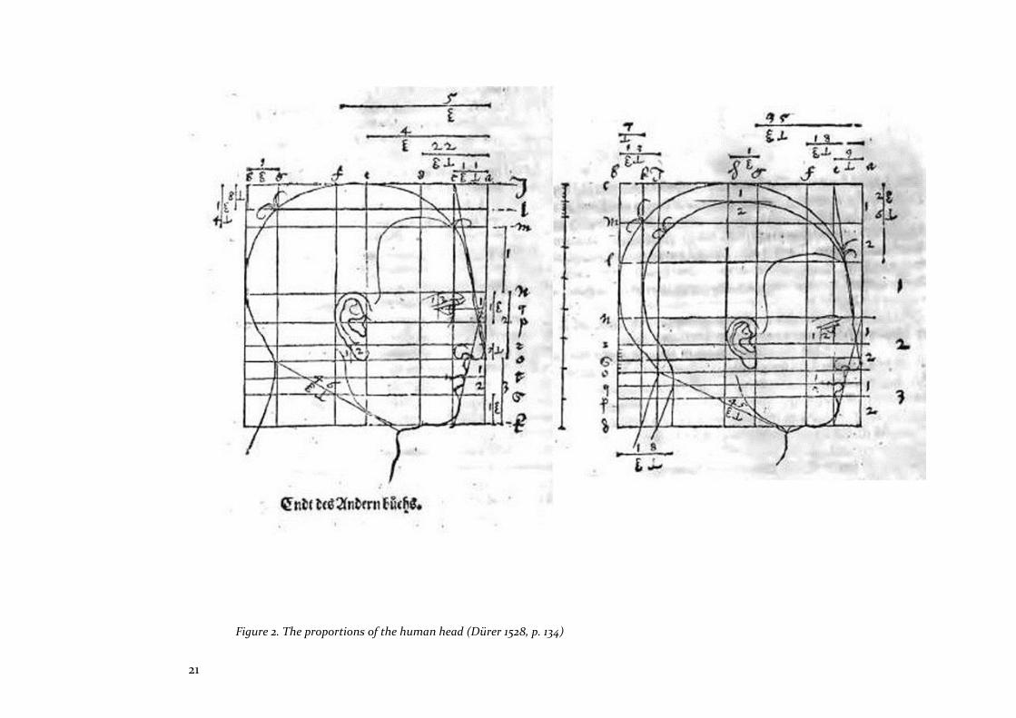
In the 16th century, however, Albrecht Dürer, unlike Alberti
and Palladio, appeared less concerned with authorship and
ideals of harmonic proportion, and more interested in
techniques which prefigured late 20th century parametric
modelling. An illustration of Dürer’s version of Alberti’s
‘perspective machine’ was published in The Painter’s Manual
(Dürer 1525, pp. 182-183). He used this and other tools to study
proportion and the relation of human body parts to the whole
body, and also examined topological associations and
constraints to create variations of form. This could be an
account of what today is termed ‘parametric’ or ‘constraint’
modelling’, its fundamental characteristics defined by Robert
Woodbury in Elements of Parametric Design as follows:
‘”marks”, that is, parts of a design, relate and change together
in a coordinated way’ (Woodbury 2010, p. 11). These
characteristics are illustrated in Dürer’s Four Books on
Proportion where, in the third part of the book, when
exploring dissimilarity and transformation of form, he adjusts
the proportions of the human head using mathematical rules
(Figure 2).
21
Figure 2. The proportions of the human head (Dürer 1528, p. 134)
22
With similarly far-reaching outcomes, an alternative but
parallel course to the application of Vitruvian classical rules
was taken by Jean-Nicolas-Louis Durand, who was professor
at the École Polytechnique (Paris, France) from 1795. Antoine
Picon remarks that Durand’s work, Précis des leçons
d'architecture données à l'École Polytechnique (1802-05),
analyses classical forms in a combinatorial manner,
identifying types defined by function and usage for modular
combination into a system (Picon 2000, p. 49). Reyner
Banham similarly describes this as a ‘particulate’ approach to
design, involving a clear identification of parts of buildings, a
characteristic of neo-classical architecture (Banham 1960, pp.
20-21). As William J Mitchell observes in his influential book
The Logic of Architecture (1990, p. 149), Durand’s rationalist
approach began from the bottom-up, with axes, grids and
primitive shapes formed into ‘skeletons of construction lines’,
followed by a top-down process to refine the floor plan,
comprising a ‘…recursive process of top-down substitution’
(Mitchell 2001, p. 1).
In Vitruvius Redux (2001), Mitchell further criticises the
classical idea of particulate composition. He regards this as
the singular failing of architectural CAD which ‘reified these
well-established design traditions’, thus limiting the
architect’s imagination and, in particular, obscuring the
architect’s capacity to read shapes and sub-shapes during the
design process (Mitchell 2001, p. 11). Nevertheless, as noted by
James Curl, Durand had inadvertently developed the notion
of repetitive, standardised, and modular elements, attributes
which anticipated the manufacture of industrialised building
components (Curl 2006). This is an opinion supported by
Picon in his study of Durand’s work:
Any building as a whole is not and cannot be other than the result of the assembly and combination of a greater or lesser number of parts. (Picon 2000, p. 188)
At the turn of the 20th century, systems of design and
production retained notions of the primacy of the architect
as author, committed to controlling identical reproductions
of their work. Additionally, the industrial revolution, in order
to achieve economies of scale, enshrined standardisation and,
therefore, identical reproduction, as essential attributes of
mass produced products. These ‘instances of identicality’
were to shape the development of modern and contemporary
architecture, and highlighted the fragmentary nature of the
system within which architectural design and production
operated (Carpo 2011, p. X).

23
2.2 Proportion and order
Vitruvius’s design method was based on a proportional modular system, where each modular unit was a constituent part of the building... (Carpo 2011, pp. 28-29)
Thus, Carpo describes Vitruvius’ proportional and modular
design method, which influenced later Renaissance
architects who devised methods of ordering and coordinating
parts within the whole, to ensure that proportional
relationships were understood and implemented by the
builder.
As he explains in Book 3, Chapter 1 of De Architectura,
Vitruvius derived his aesthetic theory from the Greeks who
regarded the members of the human body as properly
proportioned in relation ‘…to the frame as a whole…
transmitting to us the proper arrangement for buildings of all
kinds’ (Vitruvius 1960, p. 73). Indeed, as John Summerson
surmises, it was Vitruvius who was responsible for associating
the classical orders with the idea of personalities
(Summerson 1980, p. 14).
Palladio’s I Quattro Libri dell' Architettura (1570) enhances
the architectural design process devised by Alberti. He
addresses his book to practising architects in order, as James
Ackerman asserts, ‘…to teach usable measurements and
proportions’ (Ackerman 1983, p. 29). It was considered that
these systems of proportioning could guarantee a
harmonious architectural composition. This enduring idea
was taken up by Le Corbusier in the early 20th century, with
his system based on Fibonacci sequences and the golden ratio
(Mitchell 1990, p. 29). However, Colin Rowe, in The
Mathematics of the Ideal Villa, notes that, where Palladio’s
exact proportional volumes expressed ‘unchallengeable
clarity’, Le Corbusier’s conviction about proportion expressed
‘planned obscurity’ (Rowe 1978, p. 8).
As noted earlier, Durand’s particulate approach to design
unintentionally influenced industrial building systems. Kalay
elucidates such attempts to rationalise the creative process in
his book Architecture’s New Media, which describes the Ecole
de Beaux-Arts’ ‘composition’ theory that is centred on the
repertoire of classical forms. He compares ‘composition’
theory with ‘organic’ theory, a rational approach which was
the precursor to Louis Sullivan’s proclamation that ‘form
follows function’ (Kalay 2004, p. 200).
24
With a similarly rational and organic disposition, Rudolph
Schindler (in Chicago, 1916) explains his ideas concerning
maths, proportion, and architecture in his Church School of
Design lectures (Park 2005b). In this case, mental
computations facilitated Schindler’s conception of ‘reference
frames’ in space, a system based on a unit dimension of four
feet, which made it possible for the architect to form mental
images relative to human stature. However, unlike his
classical predecessors, Schindler’s method of dimensional
coordination extended to project coordination, and to the
manufacturers of the components. Park notes that his system
was grounded on two principles: first, parts were accurately
located in relation to the whole; second, the system
facilitated visualisation of spatial form based on a
proportional unit which the architect ‘…can carry palpably in
his mind’ (Park 2005a, p. 3038). Therefore, as Schindler’s
himself remarks, his design and construction system
remained flexible and open:
For practical reasons the unit should adapt itself to certain standard dimensions already established in our industry – lumber lengths, door and ceiling height…(Schindler 1946, p. 40)
Walter Gropius, also a European émigré in pre-World War II
USA, and a contemporary of Schindler, was similarly focused
on the idea of rationalising, and even mass-producing,
housing, as Colin Davies documents in The Prefabricated
Home (Davies 2005, p. 19). For this purpose, he worked with
Konrad Wachsmann, and it is illustrative to compare
Schindler’s work with Wachsmann and Gropius’s ‘Packaged
House’ of 1941-42, which Davies expounds as follows:
For Wachsmann the Packaged House was not really a house, not a locus for the lives of real people, not even ‘a machine for living in’; it was an abstract geometrical system, tending always towards mathematical perfection. (Davies 2005, p. 23)
Both approaches conceived of a hierarchically organised
relationship of parts to the whole, within an integrated
system. However, as Gilbert Herbert comments in The Dream
of the Factory-made House, the ‘Packaged House’ design
system was flexible and open-ended, while the construction
system was closed and rigid (Herbert 1984, pp. 254-256).
Modular coordination developed in the 1950s as an attempt
to integrate the requirements of designer, manufacturer, and
constructor. In his book, Building Systems, Industrialisation
and Architecture, Barry Russell records that The Modular
25
Society (UK), formed in 1953, furthered the idea of
dimensionally related buildings, based on a ‘basic module’ of
a 4-inch cube (Russell 1981, p. 304). Meanwhile, in Europe, a
report titled Modular Coordination in Building (1956) by the
European Productivity Agency recommended that a modular
system should be an ‘open’ system of construction, allowing
for interchangeability and the location of components in
different positions (Russell 1981, pp. 313).
Sidestepping the impact of industrialisation and architects’
attempts to retain control and impose order, Segal, a Swiss
émigré architect in the UK, found a different way to integrate
design tools with production processes. With his method, the
user drove the process, while the analogical techniques he
developed were refashioned for the digital age by the
computational design skills of others, as described in the case
study which follows.
2.2.1 Case Study 1
Walter Segal’s method and Calbuild
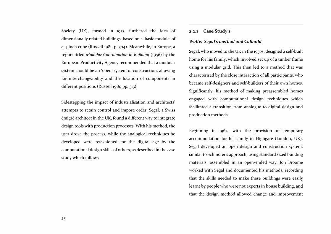
Segal, who moved to the UK in the 1930s, designed a self-built
home for his family, which involved set up of a timber frame
using a modular grid. This then led to a method that was
characterised by the close interaction of all participants, who
became self-designers and self-builders of their own homes.
Significantly, his method of making preassembled homes
engaged with computational design techniques which
facilitated a transition from analogue to digital design and
production methods.
Beginning in 1962, with the provision of temporary
accommodation for his family in Highgate (London, UK),
Segal developed an open design and construction system,
similar to Schindler’s approach, using standard sized building
materials, assembled in an open-ended way. Jon Broome
worked with Segal and documented his methods, recording
that the skills needed to make these buildings were easily
learnt by people who were not experts in house building, and
that the design method allowed change and improvement

26
with a high degree of user control (Broome 1986). Owners
sketched layouts on squared graph paper, based on a modular
or tartan grid, determined by the materials’ dimensions of
600mm or 1200mm wide (Figure 3).
Figure 4. The Segal method: house at Yelling, Cambridgeshire, UK.
1970 (Broome 1986, p. 34)
The post and beam structural frame had a thickness of 50mm,
and no cutting was needed, as walls were non-loadbearing
and could be placed in any position. Wet trades were
eliminated since components were assembled using dry
joints secured with bolts and screws. Many varieties of home
were made, including one- and two- storey buildings with flat
or pitched roofs, and double-height spaces (Figure 4).
Figure 3. The Segal method: a ‘tartan’ grid of modular panels (Broome 1986, p. 39)
27
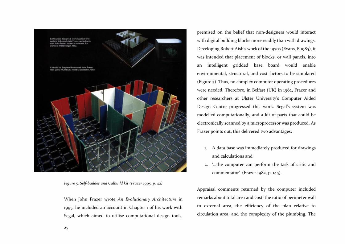
Figure 5. Self-builder and Calbuild kit (Frazer 1995, p. 42)
When John Frazer wrote An Evolutionary Architecture in
1995, he included an account in Chapter 1 of his work with
Segal, which aimed to utilise computational design tools,
premised on the belief that non-designers would interact
with digital building blocks more readily than with drawings.
Developing Robert Aish’s work of the 1970s (Evans, B 1985), it
was intended that placement of blocks, or wall panels, into
an intelligent gridded base board would enable
environmental, structural, and cost factors to be simulated
(Figure 5). Thus, no complex computer operating procedures
were needed. Therefore, in Belfast (UK) in 1982, Frazer and
other researchers at Ulster University’s Computer Aided
Design Centre progressed this work. Segal’s system was
modelled computationally, and a kit of parts that could be
electronically scanned by a microprocessor was produced. As
Frazer points out, this delivered two advantages:
1. A data base was immediately produced for drawings
and calculations and
2. ‘…the computer can perform the task of critic and
commentator’ (Frazer 1982, p. 145).
Appraisal comments returned by the computer included
remarks about total area and cost, the ratio of perimeter wall
to external area, the efficiency of the plan relative to
circulation area, and the complexity of the plumbing. The
28
computer could also make suggestions for improving
organisation.
Once the user was satisfied, the computer was instructed to
produce drawings, while the model was used for three
purposes:
1. General arrangement: using flat floor panels, giving
total area and efficiency feedback
2. Roughing-in of walls: inserted using cut circuit board,
with windows and doors
3. Final detailed design: a comprehensive kit-of-parts
was made available, including kitchen and sanitary
fittings (Frazer 1982, p. 146)
This was a pioneering attempt to use physical digital
components to make the architect-user dialogue more
effective (Evans, B 1985, p. 54). Today, this physical digital
method is referred to as a ‘tangible user interface’ (TUI), and
Frazer notes that its key advantage over the graphical user
interface (GUI) is its ‘…immediacy of response and
comprehension’, engendered by the link between the
physical model and its screen representation (Frazer 1982, p.
147). This solution brought the user’s input into the design
and production of homes, with the computer acting as an
‘intelligent’ assistant. Furthermore, it highlighted a
significant endeavour: the need to make CAD tools effective,
meaningful, and accessible for all participants.
At the heart of Segal’s process was the notion of the user as
driver of design and production, a notion which struggled
amid the onslaught of industrialisation and its impact on the
AEC sector. In order to scale-up Segal’s key lessons and
methodology to the increasing complexities of current design
and production, a better understanding of the systems and
subsystems within which design and production operates is
needed.
2.3 Systems
Architects’ desire to claim sole authorship, maintain distance
from builders, and control design, were tenable within the
prototypical system understood by all participants in the
building field before the Industrial Revolution. However, the
Industrial Revolution changed the nature of the
methodology, weakening the grip of these tenets, and
29
eventually overtaking these norms of practice. To a high
degree, modular coordination can be interpreted as a means
to maintain control.
Amid the increasing complexity and fragmentation of design
and production processes, System Theory provided some
clarity regarding methods for successful integration. In 1950,
Ludwig von Bertalanffy (2008) began noticing systemic
similarities in the sciences and social sciences, which held a
mechanistic view of the world such that, ‘…all phenomena are
ultimately aggregates of fortuitous actions of elementary
physical units’ (von Bertalanffy 2008, p. 165). This
interpretation regarded natural and social phenomena as the
only measure of reality; consequently, all could be explained
in terms of cause and effect. However, von Bertalanffy’s
General System Theory (System Theory) replaced this
interpretation with the proposition that ‘dynamic interaction’
was the unique measure of reality, and the intention of
System Theory was to provide science with an all-inclusive
doctrine of ‘wholeness’. Russell suggests that it is these
‘interacting forces’ within an open system which architects
should acknowledge:
… intuitive or explicit, there has to be a recognition by architects of the interacting forces in an open system. Using this open system in a responsive and responsible way can offer new and original results as well as drawing sensitively on tradition. (Russell 1981, p. 705)
However, in search of lessons from System Theory that might
be relevant to architects’ design tools and methods of
prefabrication, a cautious approach is needed. For instance,
the creative design process has been described as a ‘wicked’
problem, ill-defined, and difficult to constrain; the focus of
System Theory, on the other hand, is the scientific or
engineering design process, which has been described as a
‘tame’ problem that progresses linearly from analysis, to
synthesis, to solution (Rittel & Webber 1973, p. 160).
Nevertheless, one aspect of System Theory attracted
architects’ attention: its description of an open system.
Russell described this in more detail as a system which
interacts with a ‘specific environment’, and in which energy
can flow in and out to maintain its ‘homeostatic’ state
(Russell 1981, p. 687). Superficially, it would appear that the
openness of open systems, as a key feature of design and
construction systems, would be of wider interest to designers,
and of greater utility to other participants, than closed
30
systems. Again, however, Russell asserts that this interest in
open systems should be broad rather than narrow, and
should consider the nature of the overall system and its inter-
related parts, including the building’s structure; its fabric and
servicing; its cultural and social context; the people who use
it; and what happens over time (Russell 1981, p. 695).
Alexander attempted to provide a more relevant and holistic
understanding of System Theory, with his postulation of
‘unself-conscious’ architecture, as exemplified by vernacular
architecture (Alexander 1964). He distinguishes the ‘self-
conscious’ architectural outputs of his time as ‘misfits’,
victims of the overwhelming complexity of the design
problem. He urges reorganisation of the system with the
formation of concepts and subsystems suitable for the control
of ‘fit’. Refuting the traditional role of architect as sole author,
Alexander also notes that adaptation, development, and
invention are limited when the individual designer takes
control of the process:
The artist’s self-conscious recognition of his individuality has deep effect on the process of form-making. Each form is now seen as the work of a single man, and its success is his achievement only. (Alexander 1964, p. 59)
A more subtle understanding of System Theory’s relevance to
design and production processes is provided by Herbert
Simon’s concepts of the ‘decomposable’ and the ‘nearly-
decomposable’, which introduced models that disclosed the
interplay between parts and the interaction within parts, and
which placed emphasis on the characteristically hierarchic
structure of complex systems (Simon 1996). With Simon’s
analogy, successful complex systems evolved from simple
systems more rapidly if there were stable subsystems than if
there were not. Simon went on to compare ‘decomposable’
systems with ‘nearly-decomposable’ systems: in the former,
subsystems are independent of each other with no
interactions, such as gas molecules; in the latter, intense
dynamic interactions occur within parts, and weak (but
essential) dynamic interactions occur between parts (Simon
1996, p. 197).
From von Bertalanffy and Simon’s analyses, it can be
suggested that ‘open’ and ‘nearly-decomposable’ are
characteristic of openly interactive systems, where ‘closed’
and ‘decomposable’ are characteristic of closed, non-
interactive systems. Hence, in relation to architects’ design
tools and production processes, an open, ‘nearly-
decomposable’ system would allow interaction among their
31
parts, tools, or subsystems, whereas a closed, ‘decomposable’
system would allow no interactions. To ground this in terms
of the hypothesis— that integrated computational design
tools combined with compatible prefabrication techniques will
lead to better housing alternatives —it is conjectured that
better understanding of dynamic interactions between these
tools and processes is required for this change to be effective
and meaningful.
2.3.1 Measure of Integration
The above conjectures are now developed in more detail to
define a Measure of Integration (MoI), which is devised (in
this research) as a means of evaluating computational design
protocols, methods and tools.
The MoI is founded on five key features derived from an
examination of the characteristics and qualities expected to
be found in well-integrated complex systems. Inevitably,
there is some overlap between the features and attributes of
the integrated system defined here because its key qualities
of openness and dynamic interaction range across
technological and management based protocols, tools, and
methods.
Openness
As noted above, von Bertalanffy postulated Systems Theory
which observed that living organisms are characteristic of the
state of open systems where there is inflow and outflow of
materials, and that it is interaction between organism and
environment which is absent from the mechanistic world
view. In this research, this ‘doctrine of wholeness’ is
condensed into the notion of integration, while the concept
of open systems is abbreviated to ‘openness’, a significant and
sometimes coveted, feature of well-functioning systems. For
example, in his book The Open Work, Umberto Eco
acknowledges the significance of ‘openness’, reasoning that
the artist should leave some parts of a work to the public or
to chance, because its ‘”openness” and dynamism... make it
susceptible to a whole range of integrations’ (Eco, Cancogni
& Robey 1989, p. 20). In the same vein, but in the context of
the AEC sector, Carpo observes that openness and
participation ‘by even nontechnical agents’ could result from
BIM as a benefit beyond its bureaucratic rationale (Carpo
2011, p. 125). It is implied by these examples that ‘openness’ is
beneficial and this view is reinforced where ‘open’ is often
conjoined to define a desirable concept: for example, open-
source is a decentralised software development model that

32
encourages open collaboration, while open-design is a form of
co-creation where the final product is designed by the users,
both terms emerging in the late 1990s (Wikipedia 2018b,
2018c); in a similar manner, open-access encourages
unrestricted online access to scholarly research which may
include a Creative Commons license to promote reuse
(Wikipedia 2018a). Hence, founded on von Bertalanffy’s
notion of open systems, openness is the first key feature of
the MoI.
Interoperability
According to Afsari et al, ‘Interoperability... is considered the
ability of data exchange and integration’ (Afsari, Eastman &
Shelden 2016, p. 909). Additionally, Chen and Maver observe
that while tool interoperability fosters design integration it
should be combined with a collaborative context which
facilitates human-human interaction (Chen, Y & Maver 1997,
p. 24). Writing in 2000, Fischer et al bemoaned the lack of
interoperability and operability between AEC sector software
applications, considering them to be ‘static, non-
interoperable’ and requiring excessive manual maintenance
(Fischer, Burry & Woodbury 2000, p. 149). Hence,
interoperable standards are essential to ensuring ‘inter-
domain communication ...beyond the boundaries of locally
implemented software’ (Fischer, Burry & Woodbury 2000, p.
154). Commenting on the difficulties of exchanging data
using IFCs, Pazler & Turk noted that:
...end users practicing interoperability in day to day work still cannot blindly trust the mapping process. (Pazlar & Turk 2008, p. 378)
More recently, Afsari et al have focussed on the challenges of
BIM data integration and interoperability noting a gap in the
research for cloud-based-BIM interoperability where,
ironically, vendors are developing solutions in isolation,
risking problems similar to those experienced by
conventional desk-top applications (Afsari, Eastman &
Shelden 2016, p. 908). Thus, interoperability, which enables
data to be interlinked so that queries may be answered across
different databases (Kalay 2004, p. 154), is included as the
fourth key feature of the MoI.
Collaboration
Openness enables collaboration, as exemplified by initiatives
in the AEC sector which nurture team working facilitated by
risk-sharing agreements between participants e.g. Partnering
and Integrated Project Delivery (AIA 2007; Egan 1998;
33
Latham 1994). But, as Carpo observes, collaboration is now
assisted by ‘digitally supported social participation’ (Carpo
2011, p. 114), and again, he singles out BIM as a potential
catalyst for its advancement. Collaboration is the second key
feature of the MoI.
Dynamic Interaction
von Bertalanffy identified ‘dynamic interaction’ as an
essential constituent of System Theory which was depicted as
‘a scientific doctrine of wholeness’, a response to the
perceived weakness of a mechanistic world view (von
Bertalanffy 2008, p. 112):
The attitude that considers physical phenomena as the sole standard measure of reality, has led to the mechanisation of mankind and to the devaluation of higher values. (von Bertalanffy 2008, p. 165)
Expanding on this theory, Simon refers to ‘interaction’ among
subsystems during an examination of the features of adaptive
complex systems. For example, Simon notes that intra
component linkages are generally stronger than inter
component linkages. In the context of architectural design
systems, this could infer the following: that ‘intra’, meaning
inside or within, could denote the knowledge or intelligence
embodied in an element or component e.g. labelling,
performance and material properties, spatial location and
direction; or that ‘inter’, meaning between, could denote
relationships between elements or components e.g.
parametric associations, rules of association and constraints
placed on elements’ and components’ behaviour. Reinforcing
this notion of interaction Simon describes better ways to
manage complexity as follows:
When information is put in outline form, it is easy to include information about the relations among the major parts and information about the internal relations of parts in each of the sub outlines. (Simon 1996, p. 206)
This could describe the process examined later-on in Chapter
6 where modelling templates are set up to define inter
relationships utilising a topological framework, parametric
relationships, rules and constraints. In other words, the
relevance of this method of organising complexity is already
understood by those utilising computational design
processes in architecture, and the MoI is an attempt to codify
those features and attributes. Hence, these special meanings
of interaction – weak/inter/between, intense/intra/within -
have been included as sub-features of the key feature of
‘dynamic interaction’ anticipated as present in an

34
architectural design system which is whole or integrated, and
which is therefore the third key feature of the MoI.
Operability
Operability simply means ‘able to perform’, a concept closely
related to maintainability and reliability, which facilitate
consistent performance. In the AEC sector, the term ‘fit-for-
purpose’ signifies the operability of the built entity. However,
as Designing Buildings Wiki recently suggested, the
construction industry’s knowledge may itself not be fit-for-
purpose to support the standard of performance expected,
due to the proliferation of digital publications which are
difficult to control and manage (Designing Buildings Ltd
2017, p. 6). In the context of the project management of
industrial projects, Brito et al assert that commissioning is
the means of achieving operability and ‘shall be considered a
responsibility of integration management’ (Brito et al. 2015,
p. 73). Operability is a fundamental feature to be expected of
an integrated architectural design system and is included as
the fifth key feature of the MoI.
These features and their sub-features, which describe how
such a system might be defined in relation to the
architectural design process, are captured in the MoI. Codes
are defined to assist with identification later-on when the
three projects discussed in this thesis are examined in
Chapter 10. These codes are:
Op Openness
Protocols, tools, and methods utilised in combination
are independent of a particular supplier, but allow
interactions and exchange of feedback.
Io Interoperability
Protocols, tools, and methods used in combination
are able to be exchanged with each other without
affecting the functioning of the system, and without
data loss or errors. It includes the ability to share and
re-use knowledge from:
1. Multiple software platforms linked to component
and federated models that utilise common
exchange formats e.g. Industry Foundation
Classes (IFC), or customised scripts
2. A single software platform with a single shared
model e.g. Product Lifecycle Management (PLM)

35
C Collaboration
1. Digital entities and participants are able to work
together to create or achieve objectives via a data
management system (e.g. Aconex), or PLM
platform.
2. Communication between operations and
participants is facilitated via Partnering or IPD.
D Dynamic interaction
1. Weak but essential dynamic interactions occur
between tools and methods and components, via
parametric relationships.
2. Intense dynamic interactions occur within tools,
methods, and components, via, encapsulated
knowledge and intelligent feedback.
O Operability
1. Protocols, tools, and methods are operable (e.g.
effective, user-friendly), reliable (e.g. robust),
supportable, and maintainable.
2. Intelligibility and the cognitive burden are
proportionate to the task.
3. Affordance is appropriate i.e. ‘…the potential of
the technology to enable the assertive will of its
user’ (Kalay 2004, p. 476).
This MoI is used to gauge the degree of integration of the
computational design tools and prefabrication techniques
(examined later in Chapters 6 to 8) that focus on live
prefabrication home projects. It is also used in Chapters 9 and
10 to formulate a more complete understanding and means
to rate integration intensity utilising the Integrated Modelling
(IM) methodology.
The IM rating tool proposed here is based on the BIM model.
In the UK, BIM Level 0-3 ratings are the accepted definition
of the criteria required for an AEC company’s approach and
projects to be deemed BIM-compliant (NBS 2014). The
National Building Specification (NBS) UK defines these levels
as follows: Level 0 means no collaboration; Level 1 comprises
a mixture of 3D and 2D CAD, a Common Data Environment
(CDE) to encourage collaborative working; Level 2 involves
collaborative working with CAD exported to a common file
format (e.g. IFC) and compliance with guides developed by
NBS and the British Standards Institute; Level 3 has not yet

36
been fully defined but may include ‘Open Data’ standards and
new contractual frameworks to encourage open,
collaborative working. Significantly, there is no mention here
of a technological change which would foster a fully
integrated BIM Level 3 rating i.e. a single shared model, as
utilised in the manufacturing sector. Nevertheless, this rating
system is effective in simplifying the complexity of the BIM
process itself.
However, the objective of the IM tool is more specific than
the BIM rating tool, because it aims to identify impediments
to integration, and to appraise the range of features and
attributes that constitute fully integrated architectural design
systems. The IM rating tool is described in more detail in
Chapter 10.
2.4 Summary
This Chapter has examined the development of architectural
design methods and production processes from a
prototypical system of authorial control and order where
design was separated from building, to its fragmentation
during the Industrial Revolution, as manufacturing increased
its influence. It has also noted off-shoots from the classical
tradition which foreshadowed modern computational design
and prefabrication methods; for example, in the 16th century,
Dürer focussed less on the control of design intent, and more
on constraints that manipulated design relationships,
utilising the ‘veil’, as noted by Carpo (2011, p. 58). This focus
is similar to current parametric modelling techniques. Later,
in the 19th century, Durand proposed combinatorial
techniques of design, which predicted the industrialised and
standardised methods of 20th century building systems, as
noted by Curl (2006).
The ordering of parts in relation to wholes had been a
preoccupation since Vitruvius in the 1st century BC, primarily
as a means of hierarchically organising harmonic
proportions. However, with less control over design
outcomes, modular coordination became, during the early-
20th century, a means to organise and frame building
components, and to ensure that ratios and proportions were
met, while reasserting architect’s relationship with industry.
Schindler, for example, devised ‘reference frames’ in space.
Meanwhile, from the 1960s onwards, Segal showed how such
techniques could be part of a user-led process. He merged his
analogue ‘tartan’ grid system with a pioneering physical
37
computational design approach; this also provided textual
and visual data, alongside commentary appraisals, to improve
the design process for the user. But, as Kalay observes, since
Segal’s experiments were carried out in the late 1970s
computational power has risen exponentially in accordance
with Moore’s Law and, combined with the Internet, this has
transformed the design process across professions,
organisations and locations:
By embedding interconnected computational devices in both the building components themselves and the means of assembling them, the process of construction and its products will become more ‘intelligent’. (Kalay 2004, p. 396)
During the mid-20th century, System Theory introduced the
concept of ‘dynamic interaction’ as the fundamental measure
of reality. The theory suggested ways that complex design and
production processes might successfully integrate, in the
context of design as a ‘wicked’ problem. Open systems,
suggestive of flux and the interchangeability of parts, and
‘nearly-decomposable’ systems which highlighted
interactions between and within parts, are postulated here as
criteria for measuring the degree of integration achieved by
computational design tools and production systems.
Encapsulated in the MoI, their specific features and attributes
are made explicit for the purposes of evaluation in Chapters
6 to 8, which focus on project work. They are discussed in
Chapter 9, and form the basis of the IM methodology
described in Chapter 10.

38
Up to the present time, generation of the computationally
designed model has been defined as ‘creation in the pursuit
of form-finding’. Here, it is defined more specifically to mean
set up of the framework of the design, marking a transition
from conceptual to developed understanding. ‘Set up’ (verb)
is introduced here as a particular phenomenon of the
computational design process, the act of initial generation or
inception of a parametric model which promises relational
interoperability, and which can be facilitated or hindered by
the interface (typically a GUI) and the degree of interaction
available to the designer. As Terzidis observes, in Algorithmic
Architecture (2006), computational design reduces ‘…a
process into discrete patterns and the articulation of these
patterns into new entities to be used by the computer’
(Terzidis 2006, p. 39). Set up is the beginning of this process.
Hence, it is the verb, rather than the noun, the process rather
than the product, which is addressed here. Terzidis goes on
to explain why it is important to view computational design
as a process:
…then the emphasis is placed on understanding, distinguishing, and discerning the means by which design can enter the world of computation, and not the other way around. (Terzidis 2006, p. 39)
The computational design interface—the ubiquitous GUI
consisting of keyboard, mouse, monitor and applications—
might cause hesitation as it intercedes during set up of the
design framework, a process described by Burry (2007) as the
formation of the ‘design domain’:
It is the definition of the domain which is at the very front of the design process. It is an open starting point, a point that permits both commitment and deferral for the same attribute simultaneously. (Burry, J 2007, p. 615)
Additionally, when ambiguity fades and certainty forms,
there might be a reluctance to implement parametric
modelling design tools, thus impeding development of
complementary prefabrication methodologies. This
reluctance partly depends on the degree of interaction
available, which is determined by the range of human-
computer relations allowed by the interface and, in turn,
influences the process of set up. For example, transferring
from concept sketch to computational design could benefit
from a more interactive experience, which includes a critical
feedback loop, commentary, and appraisal, as provided by
Frazer’s Calbuild (1995), as noted in Chapter 2. It is the
characteristics and difficulties experienced during the
3 Generation and set up

39
process of set up, when computational design tools are
initially implemented, which are examined here.
3.1 Set up
The world of computational design is quite different from the manual world of design. (Terzidis 2006, p. 39)
According to Lawson (2005), at the very least, the client,
designer, user, and legislator all have input into generation of
the design solution. However, while the designer is
traditionally the author of these initial ideas, following on
from Vitruvius and Alberti’s conceptions, today, the
computer can suggest inconceivable options where human
thoughts are complemented and extended by its capabilities.
For designers, however, application of these computational
design tools to explore, implement, and develop, is not an
unequivocal exercise. For example, Aish suggests that to
mitigate the complexities of set up, a parametric model could
utilise a ‘control rig’ to capture the intended logic of the
structure ‘…in a form which is understandable, editable and
re-executable’ (Aish 2005, p. 13). Robert Woodbury et al.,
describe the ‘jig’ in a similar vein, as a pattern for parametric
modelling which ‘…should appear and behave like a
simplified version of your end goal’ (Woodbury, Aish & Kilian
2007, p. 223). However, perhaps these parametric modelling
tools, intended to define and constrain a bottom-up process
where the future positioning of components is unknown, are
too restrictive for architectural projects.
More significantly, these methods of setting up the design
framework reveal the nature of the problem, which is that
manufacturing design tasks progress differently to creative
design tasks. In the manufacturing sector, set up of the design
intent is inherently inflexible as it proceeds from sketch, to
shape, to part and assembly, and it is not expected to be
fundamentally changed by parametric variation. In this
context, set up of design intent would be described
reductively as a top-down process, a plan of how to construct
a model in order to properly express its visual and functional
characteristics. This reflects the kinds of uncertainty
encountered in engineering tasks, where change can be
required within the product’s system, or be due to some
unforeseen glitch in the data, but where the whole system is
not likely to change. Daniel Schodek et al. (2005) note that
this is the main reason why it is difficult to set up
architectural projects using manufacturing-oriented, or

40
‘feature-based’, computational design methods such as the
‘control rig’ or ‘jig’:
This need for thorough planning of the digital model is probably the most prohibiting factor in the use of feature-based environments during earlier design phases, with their unpredictable design changes. (Schodek et al. 2005, p. 202)
A study by Jane Burry and Dominik Holzer (2009) supported
this conclusion by focusing on the ability of manufacturing
CAD tools to link changes by automatically updating the
model, and by making all artefacts parametrically variable. It
was an experiment described as a ‘wild rally drive’ through
the early design stages to extract new knowledge, using Gehry
Technology’s Digital Project/CATIA v5; however, a key
advantage of the software was its ability to avoid
‘interoperability gaps’ and ensure ‘good transfer of design
data’ (Burry, J & Holzer 2009, pp. 338). However, the
overriding disadvantage concerned its restrictions on
creativity, its ‘tendency towards very rigid protocols and
hierarchical structures of model objects and modelling role’
(Burry, J & Holzer 2009, p. 339).
This suggests that, when setting up the framework for
parametrically modelled AEC projects, in contrast to
manufacturing projects, a deeper understanding of the kind
of change which needs accommodating is required. Hanna
(2014) compares the nature of uncertainty in creative design
tasks with that of engineering design tasks. Hanna observes
that, for the creative designer, the generation of design is
characterised by ‘ontological uncertainty’, reflected in the
fact that it is the properties and relations between design
criteria that are changed:
Inherent to the process of creative design is that these representations are constantly under change and revision, and it is this act of revision to our ontology that is the key. (Hanna 2014, p. 2)
Significantly, then, it is the abstraction of concepts or
representations based on instances—objects, models,
sketches—rather than the process of generating the instances
themselves, which is at the core of creative design. With this
additional understanding that the jig or rig is better
conceived of as an abstracted concept, its assembly can be
improved in the knowledge that its properties and relations
can change completely to represent the design intent.
41
Ideally, the computer would be an intelligent adjunct to the
designer engaged in the process of setting up a project. As
noted in Chapter 2, Frazer’s intelligent building blocks for
Segal’s self-built homes in the 1980s, returned commentary
and performance appraisals to users, exhibiting greater levels
of interaction than many CAD platforms currently provide.
Furthermore, set up of workflow is presently complex and
laborious because parametric relationships are defined
manually. In future, a solution could emerge from the
artificial intelligence (AI) technique of machine learning,
which is considered by Andia and Spiegelhalter (2015a, p. 25)
to be the successor to parametric modelling. For example,
when combined with optimisation techniques, it has
demonstrated automatic generation of 2D and 3D residential
building models, as documented by Professor Vladlun Koltun
and Paul Merrell at Stanford University (Merrell, Schkufza &
Koltun 2010). Such a computational design tool would
represent the intelligent and effective assistance that
architects hope for during transition between concept and
detailed design stages. Nevertheless, and as Frazer (1995)
remarks, the very beginning of the design process will
probably remain a mystery of human invention:
The prototyping, modelling, testing, evaluation and evolution all use the formidable power of the computer, but the initial spark comes from human creativity. (Frazer 1995, p. 19)
Inception, set up of the concept ready for development,
optimisation, and realisation remain difficult and complex
tasks when using computational design tools. However, it is
clear that the labour-intensive content of all these tasks will
eventually be substituted by more intelligent automated
techniques, as is the case with labour-intensive activities in
many other sectors. However, it is less certain that human
creativity and intuition can be replaced.
3.2 Interface
Today’s stilus is not the style of the designer but the inevitable trace left by the software being used which, just as Cicero’s stilus was, is itself man-made and produced by specialized technicians. (Carpo 2011, p. 100)
The interface affects how the computational design project is
set up, and is dependent on the different media used, for
example: the ubiquitous GUI (including computer, mouse
and monitor); the TUI employed by Frazer; virtual or
augmented reality with goggles and headsets (VR/AR); or,
photogrammetry with camera and photographs. These tools,
42
with their different interfaces, affect the way that the user
imagines and acts on their ideas, a correlation which pre-
dates computers and which has, therefore, been influenced
by earlier developments. Carpo (2011) records that Alberti’s
15th century digital experiments foretold modern
photogrammetry, which uses laser scanning techniques to
create a point cloud, as utilised by Frank Gehry to capture
formal intuitions:
…his treatise on sculpture, De statua, includes the lengthy technical description of another improbable machine, this one meant to scan human bodies and translate them into lists of three-dimensional coordinates. (Carpo 2011, p. 55)
Many tools which have transitioned from the analogue to the
digital era are available as applications in the advanced CAD
used in the manufacturing sector. Arguably, integration can
only be complete if all these applications are available for set
up of the AEC project, so that their ‘trace’ or style can be
evaluated more evenly against the design intent. The
manufacturing sector recognises the need to have these tools
available, whereas the AEC sector relies on a fragmented and
limited collection of similar tools; often, therefore, the trace
of the interface of a particular software—in particular, the
functioning and operational methods of its applications—is
apparent.
3.2.1 Alternative AEC interfaces
However, AEC educators and researchers have engaged with
a variety of computational design tools commonly used in
other sectors. Notably, Marc Aurel Schnabel’s ‘immersive
virtual environment design studio’ experiments (VeDS) used
virtual reality headsets to understand how designers perceive
architectural space within virtual environments when
creating and collaborating with team members:
The design process becomes more immediate, in some aspects, with the tools available enhancing the translation of the designers’ and users’ mental intention into spatial objects and 3D design decisions. (Schnabel, Marc Aurel 2011, p. 186)
Such an approach could ensure that all parties have up-to-
date versions of a design, and that revisions and errors are
reduced But, the material realisation of design using VeDS
remains problematic and further research is needed to assess

43
whether rapid prototyping and digital fabrication can
mitigate these problems.(Kalay 2004, p. 196).
Earlier studies by Professor Tom Maver at the Architecture
and Building Aids Computer Unit, University of Strathclyde
(ABACUS) from the 1970s to 1990s, focused on a user
participation interface supported by innovative
computational design tools. For example, PARTIAL
developed with Aish between 1975 and 1979, made plans from
users’ sketches; these were objectively appraised by a
computer, and provided far more alternatives than an
architect could ever achieve (Aish 1977, p. 10) (Figure 6).
3.2.2 Parametric modelling
Also, as noted in Chapter 2.1, parametric modelling, which is
currently the most pervasive computational design method,
has several aspects that can be traced back to Dürer’s
explorations (in the 16th century) of human figure
transformations subjected to constraints. However, in the
AEC sector today, parametric modelling is intrinsically
Figure 6. Appraisals of a nursery school’s functionality, utilising PARTIAL (Aish 1977, p. 1)
44
coupled to its GUI, introduced to the world in 1963 by Ivan
Sutherland with his thesis, Sketchpad:
…ideas introduced in Sketchpad still influence how every computer user thinks about computing…being one of the first graphical user interfaces. It exploited the light-pen, predecessor of the mouse, allowing the user to point at and interact with objects displayed on the screen. (Sutherland 1963, Preface by Blackwell & Rodden, p. 3)
However, it is seldom noted that it was a combination of
MIT’s hardware and Sutherland’s software which comprised
the GUI, where the ‘TX-2’ created at MIT in 1958 was designed
to ‘…facilitate and enhance real-time human-computer
interaction’ (Sutherland 2012, p. 82).
Concurrently with Sutherland’s experiments, aircraft and
automobile companies began developing parametric surface
and solid modelling capabilities into fully integrated
advanced CAD systems. In 1977, CATI was started by a French
aircraft manufacturer, and became the Computer Aided
Three-dimensional Interactive Application (CATIA) in 1981.
Integration of product design and manufacture was achieved
by Product Lifecycle Management (PLM), conceived by
American Motors Corporation in 1985 to foster better CAD
and communication systems, reduce conflicts faster, and
store all drawings and documents in a central database. By
2014, 3DExperience/CATIA Version 6 was launched as a fully
integrated PLM system. For the first time, the AEC sector was
its target audience (Systèmes 2017b).
Conventional AEC CAD’s parametric capability emerged in
1986 with Graphisoft’s ArchiCAD, and in 2000 with
Autodesk’s Revit (Wikipedia 2017). However, parametric
relationships in AEC CAD, unlike in advanced CAD, were
largely hidden because their application was focussed on the
use of parametrically linked data to leverage the power of
BIM, rather than on the creation of parametric models and
components (Davis 2013). In summary, although the
manufacturing sector developed fully integrated closed
systems, AEC CAD has remained fragmented with a variety
of tools. However, it is aiming for better and open integration
through BIM and common file exchange protocols.
3.2.3 Declarative format
Founding his thoughts on George Stiny and James Gip’s (1971)
work on shape grammars in the 1970s, William J Mitchell led
the critique of AEC CAD limitations during the exploratory
design stage. In particular, Mitchell criticised the AEC CAD
45
interface for its intrinsic bias towards ‘particulate
composition’ as a means to generate meaningful design
(Mitchell 2001, p. 11). According to this argument, AEC CAD
simply reflected traditional design and production methods
by deconstructing compositions into graphical arrangements
of parts based on grids, axes, points and lines, which inhibited
a designer’s options for creative generation of alternatives. As
noted, Mitchell’s opinions reference Stiny and Gips (1971),
who favoured the creative rereading of shapes as the initiator
of design invention:
Our underlying aim is to use formal, generative techniques to produce good art objects and to develop understanding of what makes good art objects. (Stiny & Gips 1971, p. 125)
Mitchell also notes (1989, p. 8) that architects find the
implementation and conceptual structure of AEC CAD
challenging and, in the quest for more flexible and intelligible
design rules, argues that they should be expressed in a
‘declarative’ and ‘modular’ programming format. While
design rules in declarative format specify what the facts or
rules of a situation are they do not describe how a
computation is performed. Procedural or imperative format
design rules, on the other hand, describe the steps on the way
to achieving the end result (Kalay 2004, pp. 50-53). The
differences between these formats are further illustrated by
the user interfaces that represent them: declarative formats
include production systems that encode design rules e.g.
programming languages PROLOG and LISP, and shape
grammars, while imperative formats include text written in
programming code e.g. C# and Python.
However, the term ‘declarative format’ has a broader reach.
For example, Simon notes (1996), during a discussion of
‘declarative logic’ and its relevance to reasoning methods
used by designers, that it includes optimisation methods
which combine theories of probability and utility:
The optimization problem is to find an admissible set of values of the command variables, compatible with the constraints, that maximise the utility function for the given values of the environmental parameters. (Simon 1996, p. 116)
Accordingly, optimisation is the subject of examination in
Project 1, thus encompassing the scope of Mitchell’s proposal
that the declarative format should be advocated in the search
for more intelligible and flexible representations of design
rules.

46
3.3 Interaction
We know that building a home is a collaborative project...Once you’re satisfied with the design, Blu Homes can make your virtual dream home a reality. (BluHomes 2017)
Increasingly, the generation of design solutions is developing
into a contentious issue because of the prevalence of
cooperation and interaction in the digital environment.
Consequently, participants’ expectations compel a
proportionately greater influence in set up and generation of
design projects than previously. Prefabricated home
providers BluHomes appear to have considered these
changes with their application, ‘Blu Design Studio’, which
allows interaction with on-line customers. However, it is
questionable whether, in the AEC sector, these tools are
integrated design tools linked to production systems, or
simply a marketing tool. Nonetheless, as Carpo (2011) states,
in the manufacturing sector, it is clear that such
considerations are intrinsic to the process:
…advanced CAD-CAM systems already support and, indeed, encourage cooperation and interaction among human actors and technical networks in all stages of design and production… One can discuss, design, and
make at the same time - just as premodern artisans and pre-Albertian master builders once did. (Carpo 2011, p. 79)
Carpo’s assertion makes it clear that cooperation and
interaction are supported by PLM systems for participants
within the manufacturing sector. By contrast, with AEC CAD,
and the proliferation of digital fabrication tools linked to 3D
printing, 2D and 3D robots, it is less clear how participants
are encouraged to cooperate and interact. A re-assessment of
Maver and Aish’s participatory methods of the 1970s-90s is
relevant and instructive, although it would need updating in
the context of the digital age. Nevertheless, the double
challenge of fragmented CAD systems, and their operation
within a fragmented AEC sector, remains. Schodek et al.
(2005) observe that this hindrance to interaction with AEC
CAD systems partly results from the way that data is
represented and stored:
Ultimately, what one can or cannot do with a digital design system depends on how the underlying program is written and structured, what programming language is used, and what type of application database stores the information the user inputs during the design process. (Schodek et al. 2005, p. 181)
Most AEC CAD programs—e.g. Autodesk Revit, Bentley
MicroStation, and Graphisoft ArchiCad—have an underlying
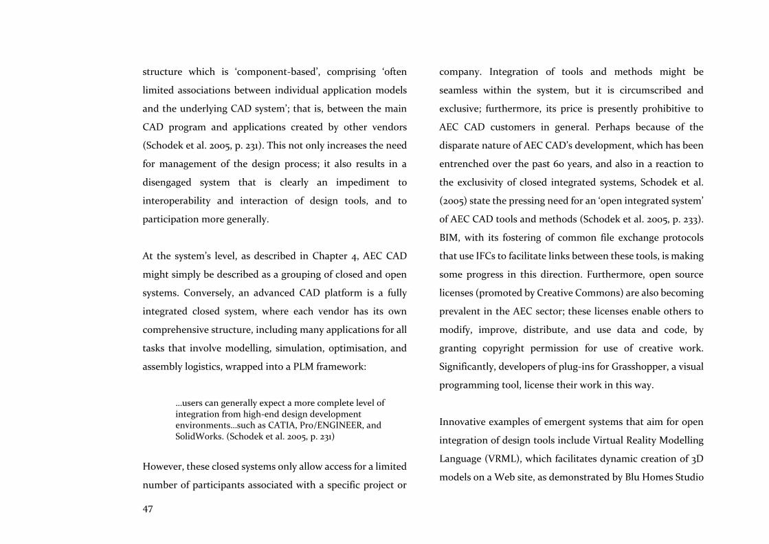
47
structure which is ‘component-based’, comprising ‘often
limited associations between individual application models
and the underlying CAD system’; that is, between the main
CAD program and applications created by other vendors
(Schodek et al. 2005, p. 231). This not only increases the need
for management of the design process; it also results in a
disengaged system that is clearly an impediment to
interoperability and interaction of design tools, and to
participation more generally.
At the system’s level, as described in Chapter 4, AEC CAD
might simply be described as a grouping of closed and open
systems. Conversely, an advanced CAD platform is a fully
integrated closed system, where each vendor has its own
comprehensive structure, including many applications for all
tasks that involve modelling, simulation, optimisation, and
assembly logistics, wrapped into a PLM framework:
…users can generally expect a more complete level of integration from high-end design development environments…such as CATIA, Pro/ENGINEER, and SolidWorks. (Schodek et al. 2005, p. 231)
However, these closed systems only allow access for a limited
number of participants associated with a specific project or
company. Integration of tools and methods might be
seamless within the system, but it is circumscribed and
exclusive; furthermore, its price is presently prohibitive to
AEC CAD customers in general. Perhaps because of the
disparate nature of AEC CAD’s development, which has been
entrenched over the past 60 years, and also in a reaction to
the exclusivity of closed integrated systems, Schodek et al.
(2005) state the pressing need for an ‘open integrated system’
of AEC CAD tools and methods (Schodek et al. 2005, p. 233).
BIM, with its fostering of common file exchange protocols
that use IFCs to facilitate links between these tools, is making
some progress in this direction. Furthermore, open source
licenses (promoted by Creative Commons) are also becoming
prevalent in the AEC sector; these licenses enable others to
modify, improve, distribute, and use data and code, by
granting copyright permission for use of creative work.
Significantly, developers of plug-ins for Grasshopper, a visual
programming tool, license their work in this way.
Innovative examples of emergent systems that aim for open
integration of design tools include Virtual Reality Modelling
Language (VRML), which facilitates dynamic creation of 3D
models on a Web site, as demonstrated by Blu Homes Studio

48
(noted above). In depth investigations of this phenomenon’s
ability to facilitate interactivity and collaboration in assembly
and construction processes have been carried out by
Schnabel’s team (at Victoria University of Wellington, NZ),
utilising the ‘immersive environment design studio’
(Schnabel, Marc Aurel 2011). Furthermore, as Schodek
comments, networks of client and server constellations have
been proposed to replace centralised servers, using Unified
Modelling Language for data object exchange, or Extensible
Mark-up Language (XML) with Java, to enable exchange of
data between different platforms over the Internet (Schodek
et al. 2005, p. 234). Case Study 2 which follows elaborates on
these emergent themes by examining two recent innovations
that are both web-based and collaboration focussed.
3.3.1 Case Study 2
WikiHouse
Based in the UK, WikiHouse is a common web platform, and
‘an open source project to reinvent the way we make homes ’
(WikiHouse 2017a). Its intention is to allow participants to
collaborate in the development of new open technologies and
standards for housing and sustainable development. To this
end, data provided by WikiHouse is open source, allowing
anyone to change it; however, it is also a host to any open-
source building system—from components to complete
house types—that can be shared as code in distributed design
to production processes (Figure 7). WikiHouse effectively
confronts BIM’s inability to penetrate the whole supply chain,
and it does this by utilising collaborative spreadsheets and
linked parametric models (e.g. Rhino/Grasshopper) that
automate design and fabrication information (Figure 8).
Hence, WikiHouse is responding to the collaborative and
interactive expectations of participants and home builders.
Figure 7. Sourced from WikiHouse Engineering Day, 3 March 2017 (WikiHouse 2017b)
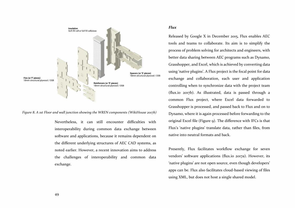
49
Nevertheless, it can still encounter difficulties with
interoperability during common data exchange between
software and applications, because it remains dependent on
the different underlying structures of AEC CAD systems, as
noted earlier. However, a recent innovation aims to address
the challenges of interoperability and common data
exchange.
Flux
Released by Google X in December 2015, Flux enables AEC
tools and teams to collaborate. Its aim is to simplify the
process of problem solving for architects and engineers, with
better data sharing between AEC programs such as Dynamo,
Grasshopper, and Excel, which is achieved by converting data
using ‘native plugins’. A Flux project is the focal point for data
exchange and collaboration, each user and application
controlling when to synchronize data with the project team
(flux.io 2017b). As illustrated, data is passed through a
common Flux project, where Excel data forwarded to
Grasshopper is processed, and passed back to Flux and on to
Dynamo, where it is again processed before forwarding to the
original Excel file (Figure 9). The difference with IFCs is that
Flux’s ‘native plugins’ translate data, rather than files, from
native into neutral formats and back.
Presently, Flux facilitates workflow exchange for seven
vendors’ software applications (flux.io 2017a). However, its
‘native plugins’ are not open source, even though developers’
apps can be. Flux also facilitates cloud-based viewing of files
using XML, but does not host a single shared model.
Figure 8. A 1st Floor and wall junction showing the WREN components (WikiHouse 2017b)
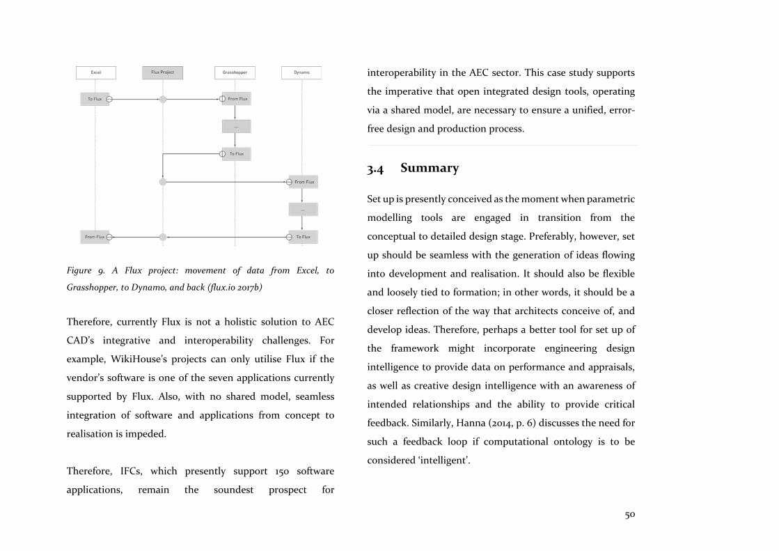
50
Figure 9. A Flux project: movement of data from Excel, to
Grasshopper, to Dynamo, and back (flux.io 2017b)
Therefore, currently Flux is not a holistic solution to AEC
CAD’s integrative and interoperability challenges. For
example, WikiHouse’s projects can only utilise Flux if the
vendor’s software is one of the seven applications currently
supported by Flux. Also, with no shared model, seamless
integration of software and applications from concept to
realisation is impeded.
Therefore, IFCs, which presently support 150 software
applications, remain the soundest prospect for
interoperability in the AEC sector. This case study supports
the imperative that open integrated design tools, operating
via a shared model, are necessary to ensure a unified, error-
free design and production process.
3.4 Summary
Set up is presently conceived as the moment when parametric
modelling tools are engaged in transition from the
conceptual to detailed design stage. Preferably, however, set
up should be seamless with the generation of ideas flowing
into development and realisation. It should also be flexible
and loosely tied to formation; in other words, it should be a
closer reflection of the way that architects conceive of, and
develop ideas. Therefore, perhaps a better tool for set up of
the framework might incorporate engineering design
intelligence to provide data on performance and appraisals,
as well as creative design intelligence with an awareness of
intended relationships and the ability to provide critical
feedback. Similarly, Hanna (2014, p. 6) discusses the need for
such a feedback loop if computational ontology is to be
considered ‘intelligent’.
51
The monitor, the mouse, and a partially parametric CAD
modelling system is the ubiquitous interface for designers in
the AEC sector. This constrains the process of creative design
and, although alternatives that reinstate the primacy of
perceptive feedback using shape grammars have been
proposed, design tools and production processes that are
seamless and fully integrated are yet to emerge. VR/AR
suggests that a different perceptual approach to intelligent
feedback and appraisal is possible. However, these tools need
collating into the AEC computational design toolbox, so that
all aspects of design intent can be considered, and the traces
of a particular software erased.
Interaction and cooperation are the norms of the digital age,
with which the AEC sector has yet to fully engage. Challenges
arise from the fragmented structure of the sector which, in
contrast to solutions in the manufacturing sector which are
closed and exclusive, itself nurtures innovative open-source
solutions. For example, the Internet is already changing
human-computer relationships in the AEC sector, enabling
open-source sharing and common data exchange among
disparate vendor applications (as the case study
demonstrates).
When designing creatively, architects hold complex
relationships in mind; thus, to be effective assistants,
computational design tools need to possess some degree of
intelligence to provide interaction in the creative design
process. As Kalay remarks, this need only involve embedding
design rules, constraints, and goals within object
representations to make ‘…it an active, rather than a passive
partner in the design process’ (Kalay 2004, p. 195), as is
common with advanced CAD tools. Architects want these
new kinds of tools as their assistants in design creativity. Such
tools require the computational power to synchronously
analyse performance, and to seamlessly resolve relationships
in space with methods of realisation.
52
Science is mainly concerned with analysis and how things are,
whereas design is mainly concerned with synthesis and how
things ought to be. However, both fields utilise simulation,
optimisation, and appraisal for determining the state of
things. This chapter examines simulation in support of
optimisation searches that are computationally directed, and
their contribution to the integration of computational design
tools and production solutions. Appraisal of optimisation
results could be computationally led, as illustrated by Frazer
(1995) and Maver’s (1970) work (cited in Chapters 2 and 3
respectively); here, however, appraisal is considered as the
human contribution of critical evaluation and feedback. As
Kalay remarks in Architecture’s New Media, appraisal might
concern measurement of a building’s performance, its post-
occupancy performance, or the effectiveness of the design
process itself. In this chapter, appraisal relates to the
‘…predictive assessment of the expected performances of
design solutions’ (Kalay 2004, p. 295).
Simulation enables us to comprehend and predict the
performance of systems without the expense of building full-
scale replicas. Physical and imaginary methods of simulation
which predate the computer include, model basins to test
ship hull design; wind tunnel simulation in aeroplane
development; and thought experiments to determine a
machine’s ability to exhibit ‘intelligent’ behaviour (Simon
1996, p. 13; Turing 1950). Model basins and wind tunnels have
been supplemented or replaced by computational fluid
dynamic (CFD) computer simulations, while Hanna’s recent
studies illustrate that the Turing test continues to stimulate
thought experiments relating to artificial intelligence (2014,
p. 5). In each case, however, reality is recreated as a model for
testing an artefact or a process, the results of which will be
appraised in relation to outcomes and expectations.
Simulations can also tell us things we do not know. For
example, the physical sciences might understand the
properties of gas molecules, but have less understanding of
their behaviour when combined. In the design disciplines,
this might be analogous to the behaviour of parts combining
within the whole. This gives rise to further considerations; as
Simon (1996) comments: ‘The difficulty of the design
problem often resides in predicting how an assemblage of
such components will behave’ (Simon 1996, p. 15).
4 Simulation and optimisation
53
Simulation incorporates analysis, and the testing of physical
or virtual models. It can influence synthesis of the design
intention as tested parts are rejected, re-made, or re-
combined into the whole. Before the synthesis, however, it
may be necessary to check that we have selected the best
results, the optimal outcomes of the analysis measured
against the expected outcomes, as defined by the program
and the design intent. The Latin ‘optimus’ means ‘best’, and
‘optimisation’ is a search for the best state in a natural or
artificial system (Burry, J & Burry 2010, p. 117). As Lawson
observes, however, there will not usually be a single best
solution resulting since design problems are complex, and
their criteria cannot be fully stated as they could be unknown
(Lawson, B 2005, p. 143).
The benefit of prefabricated solutions is that they facilitate
prediction, simulation, and optimisation. As Smith observes
(2010, p. 84), prefabricated home design and assembly
progresses concurrently, whereas conventional design and
on-site construction occurs linearly. Prefabrication’s
concurrent flows allow data to be precipitated and this, in
turn, expedites the modelling of components and modules.
Kalay (2004, p. 327) affirms that, together with models of the
conditions under which they are to be tested, this timely flow
of data forms the basis of making predictions. Furthermore,
as Lawson et al. remark, early testing of prefabricated
solutions leads to efficiency gains when performance is
optimised and waste is reduced in the design and
manufacturing processes (Lawson, M, Ogden & Goodyear
2014, p. 241).
This next section examines the value of simulation in support
of optimisation (which searches for better solutions), and
their integration as computational design tools to improve
prefabricated home design and assembly solutions.
4.1 Simulation
The conditions for architecture created by simulation seem barren in the light of traditional ideas, but may present new possibilities if seen through different eyes. (Scheer 2014, p. 192)
Lawson (2005) is similarly doubtful when describing the
ability of ‘purely evaluative’ tools to assist with synthesising
solutions, and also questions the accuracy of results about
‘highly variable phenomenon’ (sic), such as daylight, without
an integrated understanding of heat loss, heat gain, and views

54
(Lawson, B 2005, p. 72). However, and perhaps paradoxically,
it is also a key advantage that few details of the subsystem or
part are required for the purpose of simulation, as noted by
Simon: ‘We can often predict behaviour from knowledge of
the system's goals and its outer environment, with only
minimal assumptions about the inner environment’ (Simon
1996, p. 8).
Hanna (2010), expanding on this notion, states that it is not
the individual agents that count but their interactions, where
‘higher order’ behaviour becomes significant because its
predictability makes design possible, in contrast to the
complexity and unpredictability of design in general. He
notes that:
… designers typically do not need to work toward the precise behaviour of an individual at a precise moment in time, but for a varied group and over a relatively long period. (Hanna 2010, p. 2)
Simulation of higher order behaviour was demonstrated in a
study by Janssen and Kaushik (2013) which incorporated
gaming software simulations for implementation of a
development and evaluation procedure to generate point
block housing configurations on a hypothetical site in
Singapore. In this case, ‘dynamic particle solvers’ were used
to manipulate the behaviour of circular objects representing
the open spaces, pools, playgrounds, and point blocks on the
site. When defined simply as ‘particles’, these objects exhibit
higher order behaviour as positive charges are applied,
causing them to repel each other. After animation for 1000
frames, the particles or circular objects reposition themselves
to effectively resolve any overlaps (Janssen, Patrik & Kaushik
2013, p. 202).
Architects are in a better position today to view the
possibilities of simulation from a different perspective, due in
part to the pioneering work of Maver (1970), as noted in
Chapter 3. During the 1970s, having lamented architecture’s
failure to take advantage of the computer, Maver began to
outline a direction of study to understand the contribution
computers might make to design. He was particularly
concerned about: ‘…the lack of an externally valid model of
the design activity which can serve as a framework for a
taxonomy of computer design techniques’ (Maver 1970, p.
199).

55
Therefore, he began to describe, probably for the first time in
the context of CAD, those particular aspects of the computer
which complemented human activities. At the time, he
believed these were limited to the operations of analysis and
appraisal, until breakthroughs in cathode-ray tube
technology and improvements to the GUI began to widen the
scope of human-computer interaction. Even at this early
stage, however, Maver followed an approach whose goal was
a suite of appraisal programs, which would be applied to an
architect’s hypothesised solution and considered by a team of
designers, users, and all other participants. Central to this
methodology were simulations initiated by the architect’s
intuitive synthesis as a first approximation of the design
problem.
Having noted the nature of the problem, Maver went on
during the 1980s and 1990s to help make better CAD tools to
measure planning efficiency and energy efficiency, and to
integrate heating, lighting, and energy into appraisals. For
instance, ABACUS authored PACE in 1972, one of the first
integrated appraisal systems. By the 1990s, PACE had
evolved, via CUPID and PARTIAL, into GOAL, a tool which
‘numerically’ appraised geometry, construction materials
relative to climate, material costs, user requirements, and
local building regulations. GOAL was described as a
‘…knowledge-based, integrated, case-based design decision
support system’, which is confirmation of its pragmatic and
serviceable intentions (Maver 1997, p. 4). However, before
progressing further, it is important to note that some
adherents of the simulation of design models had other ideas
and ambitions because, as Terzidis (2006) remarks:
‘…architecture can be regarded as either a simulation of the
laws and structure of nature or as a world of fantasy and
imagination’ (Terzidis 2006, p. 8).
Frazer’s approach, as described in Evolutionary Architecture
(1995), investigates both of these interpretations, where
simulation facilitated evaluation of environmental
performance and was also used for ‘the development of
prototypical forms’ (Frazer 1995, p. 9). However, this section
focuses on simulation of the ‘laws and structure of nature’,
accepting the challenge of Maver’s insights by examining how
the computer can continue to assist with better predictions
of performance by increasing the likelihood of fitness of the
design intent, and thus enhancing outcomes for clients and
users. Maver’s approach emphasises a collaborative context
56
for the development of integrated design tools. During
experiments with energy simulations, however, a recurring
challenge concerned the trade-off between accuracy of the
design model and ease of use of the appraisal tools (Maver
1997, p. 3). This and other challenges were confronted by
those who followed, as computational design tools improved,
and as simulation investigated new territory amid an
increasing imperative to use resources sustainably.
4.1.1 Simulation of spatial and thermal
performance
In a study of spatial and thermal simulation methods by
Niemasz et al. (2011), a sophisticated simulation engine,
complemented by relational modelling methods, illustrated
developments towards achieving the combined goals of
accuracy and ease of use. The study formed and visualised
‘solar envelopes’ for detached residential properties,
facilitated by parametric modelling. Solar gain was measured
for its effect on heating and cooling energy use, while annual
carbon dioxide equivalents were also measured as CO2e
emissions factors for electricity or gas. Simulation was carried
out using EnergyPlus, verified to perform as would a real
building (EnergyPlus 2017). The study envisaged future
research involving even more accurate ‘multi-scalar
simulations’ by accounting for additional criteria including
transportation patterns, occupant use, and urban form
(Niemasz, Sargent & Reinhart 2011, p. 112).
4.1.2 Simulation of the design studio
Studies that simulated a collaborative and interactive design
method, while also simulating the creation of the design
model itself, were inspired by the idea of a virtual design
studio (VDS), proposed in the newsletter of MIT’s School of
Architecture and Planning in the Fall of 1993. Chen and
Maver (1996) developed the concept of a simulated multi-
user, virtual studio environment (VSE) of the future. This
included networked facilities that enabled participants to
access a virtual organisation’s servers and databases, and to
communicate using real-time messaging and video
conferencing in a fully integrated way (Chen, YZ & Maver
1996, p. 126). This idea was developed by Schnabel (2011) who
set up a learning experience for students in a virtual
environment design studio (VeDS), simulating a
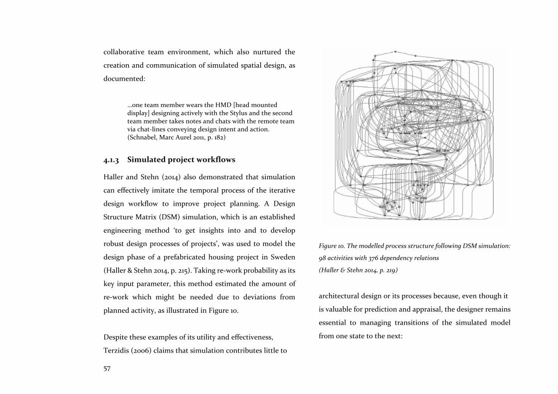
57
collaborative team environment, which also nurtured the
creation and communication of simulated spatial design, as
documented:
…one team member wears the HMD [head mounted display] designing actively with the Stylus and the second team member takes notes and chats with the remote team via chat-lines conveying design intent and action. (Schnabel, Marc Aurel 2011, p. 182)
4.1.3 Simulated project workflows
Haller and Stehn (2014) also demonstrated that simulation
can effectively imitate the temporal process of the iterative
design workflow to improve project planning. A Design
Structure Matrix (DSM) simulation, which is an established
engineering method ‘to get insights into and to develop
robust design processes of projects’, was used to model the
design phase of a prefabricated housing project in Sweden
(Haller & Stehn 2014, p. 215). Taking re-work probability as its
key input parameter, this method estimated the amount of
re-work which might be needed due to deviations from
planned activity, as illustrated in Figure 10.
Despite these examples of its utility and effectiveness,
Terzidis (2006) claims that simulation contributes little to
Figure 10. The modelled process structure following DSM simulation:
98 activities with 376 dependency relations
(Haller & Stehn 2014, p. 219)
architectural design or its processes because, even though it
is valuable for prediction and appraisal, the designer remains
essential to managing transitions of the simulated model
from one state to the next:
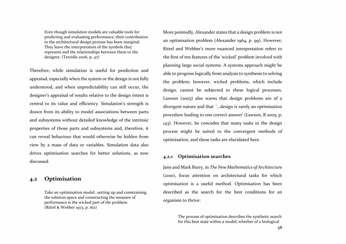
58
Even though simulation models are valuable tools for predicting and evaluating performance, their contribution to the architectural design process has been marginal. They leave the interpretation of the symbols they represent and the relationships between them to the designer. (Terzidis 2006, p. 47)
Therefore, while simulation is useful for prediction and
appraisal, especially when the system or the design is not fully
understood, and when unpredictability can still occur, the
designer’s appraisal of results relative to the design intent is
central to its value and efficiency. Simulation’s strength is
drawn from its ability to model associations between parts
and subsystems without detailed knowledge of the intrinsic
properties of those parts and subsystems and, therefore, it
can reveal behaviour that would otherwise be hidden from
view by a mass of data or variables. Simulation data also
drives optimisation searches for better solutions, as now
discussed.
4.2 Optimisation
Take an optimisation model…setting up and constraining the solution space and constructing the measure of performance is the wicked part of the problem. (Rittel & Webber 1973, p. 162)
More pointedly, Alexander states that a design problem is not
an optimisation problem (Alexander 1964, p. 99). However,
Rittel and Webber’s more nuanced interpretation refers to
the first of ten features of the ‘wicked’ problem involved with
planning large social systems. A systems approach might be
able to progress logically from analysis to synthesis to solving
the problem; however, wicked problems, which include
design, cannot be subjected to these logical processes.
Lawson (2005) also warns that design problems are of a
divergent nature and that ‘…design is rarely an optimisation
procedure leading to one correct answer’ (Lawson, B 2005, p.
143). However, he concedes that many tasks in the design
process might be suited to the convergent methods of
optimisation, and these tasks are elucidated here.
4.2.1 Optimisation searches
Jane and Mark Burry, in The New Mathematics of Architecture
(2010), focus attention on architectural tasks for which
optimisation is a useful method. Optimisation has been
described as the search for the best conditions for an
organism to thrive:
The process of optimisation describes the synthetic search for this best state within a model, whether of a biological

59
system or architectural or structural system, usually under restrictions, implied or expressed. (Burry, J & Burry 2010, p. 119)
More precisely, optimisation searches for better states
relative to others, usually involving trade-offs between
interacting or competing performance criteria. Because an
optimisation method involves trade-offs, we are not looking
for an optimal or single best solution, but rather, a number of
satisfactory solutions. Instead of optimising, Simon (1996)
prefers and introduces the term, ‘satisficing’ remarking that,
although most will only settle for best, ‘that is not the way the
problem usually poses itself in actual design situations’
(Simon 1996, p. 119).
4.2.2 Intuition and computation
Optimisation, like simulation, not only pre-dates
computational design tools but, as implied earlier, involves
evaluative methods which the computer cannot replicate. For
example, believing that computers with their inability to
discover general principles from sets of facts manifestly lack
inductive logic, Maver (1970) relies instead on human
evaluation to optimise better solutions. He explains:
… it is possible, using an intuitive synthesis as a first approximation, to explicitly appraise it [the design solution] in such a way that promotes convergence by iterative modification towards an optimum solution. (Maver 1970, pp. 204-205)
Figure 11. (Left) Maqueta funicular (Wikimedia 2017b);
(Right) Cripta de la Colònia Güell, Santa Coloma de
Cervelló (Wikimedia 2017a)
Antoni Gaudi demonstrated intuition and the importance of
the designer’s role as appraiser when he experimented with
optimisation searches for structural economy in the inclined
columns for the Church of Colònia Güell (Santa Coloma de

60
Cervelló, Spain). By attaching bags of sand to a web of strings,
he discovered the catenary curves which described the
‘masses of the static loads of the structure’, thus revealing the
resultant shape and form of the chapel’s towers (Burry, J &
Burry 2010, p. 119) (Figure 11).
4.2.3 Optimisation algorithms
Nevertheless, it is affirmed here that mathematical
algorithms support the designer’s intuition. Algorithmically,
optimisation methods can be divided into stochastic and
deterministic approaches. Stochastic routines combine a
random or probabilistic component with a selective process,
similar to aiming arrows at a target, while noting that each
state would not completely determine the next. By contrast,
deterministic optimisation routines have no randomness,
each state determining the next with the same outcome
repeated. Evolutionary algorithms use stochastic routines,
effectively using higher probabilities towards desirable
outcomes; hill climbing algorithms, on the other hand, are
deterministic, searching locally for better solutions to a
function without necessarily finding the optimum (Burry, J &
Burry 2010, p. 258; Deb 2011, p. 2). Genetic algorithms are a
type of evolutionary algorithm developed by John Holland
and colleagues at the University of Michigan in 1975, which
Holland describes in general terms as follows:
Successful analysis separates incidental or ‘local’ exaggerations from fundamental features. A broadly conceived analytic theory brings data and explanation into a coherent whole, providing opportunities for prediction and control. (Holland 1992, p. 2)
Table 1. Typical structures and operators
(Based on Table 1, Holland 1992, p. 4)
Field Performance
measure
Structures Operators
Genetics Fitness Chromosomes Recombination,
mutation, etc.
Architecture Performance rate
Objectives
Measure of fitness
Minimise/maximise
Parameters
(genes)
Objectives
(phenotype)
Reproduction,
crossover,
mutation
Holland (1992, p. 2 ) elucidates this description of GAs with
the story of blind men examining an elephant by contact
alone, each of whom will emphasise different, ‘local’,
61
aspects of its adaptation. Although the analogy between
evolutionary and architectural processes will always be
imprecise, it is reproduction and the structured, albeit
randomised, information exchange of crossover which gives
GAs much of their power. As David E Goldberg notes, it is a
process where direction and chance build new solutions from
the best partial solutions of previous trials, with mutation
playing a secondary role (Goldberg 1989, p. 14). The table
above compares the terms of this analogy (Table 1):
4.2.4 Multi-criteria optimisation
Formalisation of this evolutionary architectural process using
a GA is a description of the outcome of competition between
differently performing criteria. It is a complex process,
termed ‘multi-criteria optimisation’. It results in a trade-off
front, or a Pareto front of ‘best’ solutions, where each solution
is in a state in which a single criteria can only improve at the
other’s expense (Burry, J & Burry 2010, p. 118). Several studies
(below) exemplify multi-criteria optimisation searches
applied to residential projects, to illustrate their utility when
trading-off competing criteria.
A study by Narahara and Terzidis (2006) documents the
design of a theoretical 200-unit housing project,
incorporating multiple environmental, functional, and
economic constraints. This design traded-off better views
against the increased construction cost of adding floor levels.
In a similar vein, Patrik Janssen (2011) devised DEXEN, a
‘parallel processing networked system’. He utilises a GA and
simulation engines to generate individual housing designs,
optimised for three competing criteria: minimisation of
energy consumption (simulated using EnergyPlus);
maximisation of daylighting (simulated using Radiance); and
maximisation of privacy based on the position and
orientation of neighbours’ windows (Janssen, Patrik, Basol &
Chen 2011, p. 250). Lastly, Caldas and Santos (2012) created
GENE ARCH, linking integrated parametric modelling, a GA,
an energy simulation program, and shape grammars to
generate environmentally optimised and novel urban and
patio house designs.
4.2.5 Collaboration and optimisation
A study by Luebkeman and Shea (2005, p. 17) demonstrates
that multi-criteria optimisation, because of its multi-
disciplinary nature, can also improve the collaborative
62
experience of the design process. This was articulated when a
complex optimisation model, encoding 3x1048 possible
designs for the bracing system of Bishopsgate Tower
(London), received an enthusiastic and attentive response
from architects, Kohn Pedersen Fox (Luebkeman & Shea
2005, p. 19). Validation of the breadth of influence that multi-
criteria optimisation can have across disciplines was further
demonstrated by Aish et al. (2012), with a method used to
generate and optimise the geometry of the Great Court roof,
(British Museum, London) by Foster & Partners. This method
is defined as ‘embedded rationality,’ where the performance
assessment and form finding algorithm combine in a single
design optimisation process:
This integration of SMART Form, Robot, and Ecotect is part of a strategy to integrate a number of design tools (geometric, generative, and evaluative) into DesignScript. (Aish et al. 2012, p. 53)
These examples recall Simon’s (1996) vision, that
computational design can provide the ‘common ground’
between the cultures of engineering and design. Perhaps
more significantly, as observed by Kalay, the rules,
constraints, and goals of the optimisation process reveal the
potency of ‘intelligent’ objects (2004, p. 195). A more in-
depth case study follows. This study aims to draw some
conclusions for the use of multi-criteria optimisation as an
integrated design tool linked to production methods.
4.2.6 Case Study 3
Evins et al.
A well-cited study of multi-criteria optimisation by Evins et
al. (2012) examined a low-carbon-dioxide housing problem.
In particular, it noted the complementarity of multi-criteria
optimisation and parametric modelling, and the strengths
and weaknesses of these two computational design methods.
In this study, careful pre-planning of sub-systems, objectives,
variables, and constraints was carried out prior to
commencement of the optimisation method. Additionally,
parametric modelling was perceived to align well with
optimisation because of its holistic and flexible approach. It
was observed that accessibility to the parametric approach
was improved by visual programming methods, using both
Grasshopper and Generative Components: ‘The result is a
ubiquitous and adaptive design system that can lever
computational power to offer more possibilities in less time
compared with conventional CAD’ (Evins et al. 2012, p. 7).
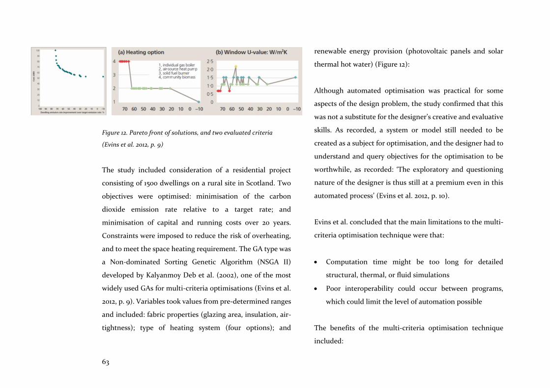
63
Figure 12. Pareto front of solutions, and two evaluated criteria
(Evins et al. 2012, p. 9)
The study included consideration of a residential project
consisting of 1500 dwellings on a rural site in Scotland. Two
objectives were optimised: minimisation of the carbon
dioxide emission rate relative to a target rate; and
minimisation of capital and running costs over 20 years.
Constraints were imposed to reduce the risk of overheating,
and to meet the space heating requirement. The GA type was
a Non-dominated Sorting Genetic Algorithm (NSGA II)
developed by Kalyanmoy Deb et al. (2002), one of the most
widely used GAs for multi-criteria optimisations (Evins et al.
2012, p. 9). Variables took values from pre-determined ranges
and included: fabric properties (glazing area, insulation, air-
tightness); type of heating system (four options); and
renewable energy provision (photovoltaic panels and solar
thermal hot water) (Figure 12):
Although automated optimisation was practical for some
aspects of the design problem, the study confirmed that this
was not a substitute for the designer’s creative and evaluative
skills. As recorded, a system or model still needed to be
created as a subject for optimisation, and the designer had to
understand and query objectives for the optimisation to be
worthwhile, as recorded: ‘The exploratory and questioning
nature of the designer is thus still at a premium even in this
automated process’ (Evins et al. 2012, p. 10).
Evins et al. concluded that the main limitations to the multi-
criteria optimisation technique were that:
• Computation time might be too long for detailed
structural, thermal, or fluid simulations
• Poor interoperability could occur between programs,
which could limit the level of automation possible
The benefits of the multi-criteria optimisation technique
included:
64
• Greatly reduced time per design option trialled (balanced
by increased set up time)
• Improvements in performance for complex problems
• Increased rigour in the design process
The advantages of simulation and optimisation, and the
potential for improvements to prefabricated home design
and assembly, have been presented here. Niemasz et al.’s
(2011) work demonstrated that energy performance
simulations can reduce energy use and CO2 emissions, while
Haller and Stehn (2014) improved design workflows for a
prefabricated housing project in Sweden. The 200-unit
housing study by Narahara and Terzidis (2006) utilised
optimisation methods to trade-off views against construction
costs, and Janssen and Kaushik (2013) utilised similar criteria
to optimise solutions for a residential development project in
Singapore. Luebkeman and Shea (2005) even showed how the
process of optimisation utilising a GA can bring design
disciplines together. Notably, the case study of Evins et al.’s
(2012) work on 1500 dwellings in Scotland, affirmed the
complementarity of multi-criteria optimisation and
parametric modelling methods.
4.3 Summary
The pragmatic and utilitarian features of simulation have
been examined in this chapter. It is clear that simulations are
useful in the early stages when design options are being
explored, and that the nature of these simulations will differ
from those carried out in the later stages. Early on, flexibility,
ease of use, and real-time feedback are needed; in the detailed
design stage, however, more time is spent setting up models
for structural and environmental performance simulations
and this process needs greater accuracy. Nevertheless,
simulation and optimisation tools are rarely utilised by the
architect in these early and intermediate stages of design
when their feedback could be most beneficial. A new
perspective on the opportunities that simulation can
contribute to architecture has been shown here including:
high level simulation of the behaviour of architectural
objects; better responses to the need to preserve resources;
and design process and workflow simulations to improve
creative possibilities and efficiencies.
While simulation and optimisation searches can be diverted
to the investigation of unimagined forms, this chapter has
explored their practical and wider applications to
65
architecture. It has also clarified the goal of optimisation
searches which, rather than offering the best solutions,
provide trade-off sets of satisfactory solutions, either for
synthesis of the design solution, or for further evaluation. The
designer remains central to this process, from their intuitive
initiation of the design model, through to querying and
understanding the objectives of the search, to playing their
part as appraisers and evaluators. As Kalay perceives,
evaluation is the ‘glue’ that joins ‘…the feedback part of each
design cycle’ (2004, p. 299).
Evolutionary algorithms, such as GAs, in their ability to
search for solutions that combine multiple criteria, are a
useful tool for AEC participants who are searching for trade-
offs between environmental, functional, and commercial
criteria, as they are able to supply many solutions to complex
problems. Real-time evaluation is of significant value to AEC
participants, especially in the conceptual stages of design
when accuracy can be traded-off for speed. It is also clear that
the process of optimisation fosters a collaborative approach
and could be of significant benefit to the integration and
better functioning of AEC design processes. Notably, as Kalay
(2004, p. 196) comments, optimisation processes contain
unelaborated, ‘embedded intelligence’ in the form of rules,
constraints, and goals which contribute effective
computational design assistance to the architect. As also
noted in Chapter 3.2.3 the declarative format includes the
technique of optimisation, thus embracing Mitchell’s
endorsement for its inclusion as a more intelligible and
flexible representation of design rules (Mitchell 1989, p. 8).
This examination of the nature of simulation in support of
optimisation, and the in-depth review of a case study
focusing on multi-criteria optimisation, prompted
explorations that formed the basis of Project 1, Chapter 6: an
examination of the challenges and benefits of multi-criteria
optimisation in the design of prefabricated volumetric
homes.
66
From its earliest industrialised conceptions of the 19th
century, prefabrication has promised time, cost, and quality
improvements compared to conventional methods of
construction. For the AEC sector, the promise would
translate into predictability, productivity, and efficiency
improvements if standardised and pre-assembled strategies
were followed. It seems that all would benefit, and yet it is a
promise that has rarely been fulfilled. However, while noting
the themes underlying these failures, this chapter focusses on
the nature and consequences of open systems of
prefabrication combined with integrated computational
design tools—a combination which could fulfil the promises
made.
Definitions of prefabrication have proliferated, but Nicholas
Habraken’s broad delineation from Supports: an alternative
to mass housing (1999) is instructive: ‘In itself prefabrication
means no more than the manufacture of housing
components in one place and their assembly in another’
(Habraken 1999, p. 67). This statement encompasses the
whole spectrum of definitions, from the manual making of
components remote from site, to mechanised methods of
production in a factory, all bound for assembly elsewhere. It
is a definition which is pliant and extensible, facilitating a
wide exploration of its synergies with computational design
methods and tools. To update the definition, ‘prefabrication’
subsumes recent advances in digital fabrication, although
these methods are not discussed in detail here.
It is important to note, however, that prefabrication is an
innovative means to an end within a complex system of
intransigent relationships. This broader context is reflected
in Steinhardt et al.’s (2013, p. 5) ‘prefabricated housing
systems innovation model’, which accounts for relationships
among policy, products, people (builders, users,
manufacturers), technology, and business processes.
However, a study by Owen et al. affirms that when working
within this complex system of relationships in the AEC
sector, the design and production process lacks integration:
Information must flow efficiently from the direction of functional utilisation and client or stakeholder requirements backwards, as well as from the designer forwards, within carefully optimized design information architectures. Only then can physical activities be optimized and integrated in a holistic manner. (Owen et al. 2010, p. 237)
5 Prefabrication
67
This chapter focusses on prefabrication methods and
computational design tools that streamline this flow, by
examining the upstream pull of contractor, engineer, and
fabricator constraints and requirements, and their effect on
the downstream push of architect and customer
expectations.
5.1 Coordination
Since dimensional coordination between all the components is essential in prefabrication, the application of a modular design is fundamental. (Park 2005a, p. 3040)
In his study of Rudolph Schindler’s work, Park (2005a)
describes an idea premised on the belief that the design of a
building could be a rational procedure. As noted in Chapter
2, this premise had also been formulated by Durand in the
early 19th century, when he systematised architectural
knowledge by classifying types from antiquity for the purpose
of identifying fundamental principles and procedures that
were to be made explicit. For this purpose, Durand’s
methodology involved composing architectural form,
beginning with set out of main axes, secondary compositional
grids, and lesser grids for placement of walls and columns.
Schindler transposed this methodology into a mental
projection that the architect could visualise at all times as a
proportional 4ft unit system, and which he defined as a
‘reference frame in space’ (Schindler 1946). It is contended
here that these rational procedures, based on dimensional
coordination techniques, evolved into modular design and
prefabrication methodologies, a progression which
recognised that integration of these tools and methods was a
motivating force.
In the United States in the early 20th century, architects were
attracted by the idea that accurate dimensional coordination
and interchangeability of parts would facilitate customer
variety and choice, and the idea of standardised dimensions
grew. For instance, Albert Farwell Bemis in his book The
Evolving House (1936, p. 62), when comparing car and house
production, concluded that coordination on a ‘cubical
modular’ basis was the key to standardisation of design and
production. For Bemis, as Davies (2005) observes, the module
referred to a standard dimension and to an intrinsic part of
the building, and was based on a 4-inch cube (Figure 13): ‘His
idea was that all building components should be made in
sizes that were multiples of the module’ (Davies 2005, p. 134).
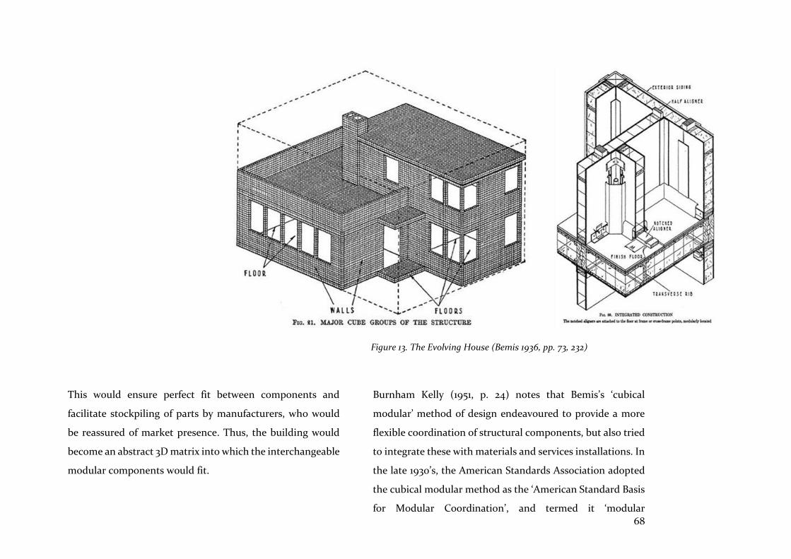
68
This would ensure perfect fit between components and
facilitate stockpiling of parts by manufacturers, who would
be reassured of market presence. Thus, the building would
become an abstract 3D matrix into which the interchangeable
modular components would fit.
Burnham Kelly (1951, p. 24) notes that Bemis’s ‘cubical
modular’ method of design endeavoured to provide a more
flexible coordination of structural components, but also tried
to integrate these with materials and services installations. In
the late 1930’s, the American Standards Association adopted
the cubical modular method as the ‘American Standard Basis
for Modular Coordination’, and termed it ‘modular
Figure 13. The Evolving House (Bemis 1936, pp. 73, 232)
69
coordination’; this, as Kelly notes, with its elimination of
cutting and fitting on site, gave impetus to the prefabrication
movement (Kelly 1951, p. 25).
However, a cautionary note is sounded by Barry Russell (1981,
p. 683) who perceived that post-World War Two building
systems based on rational procedures in Britain, consisted
mainly of factory-made groups of dimensionally coordinated
components which were self-referential and, therefore,
unable to accept components from other systems. Therefore,
it seems that, rather than System Theory principles, which
were valid for systems in general, the narrower field of
systems engineering thinking had encouraged solutions with
a technological emphasis. Hence, as Russell attests, this focus
on systematic improvements to production and efficiency
had ignored the fundamentals, including environmental
control, context, energy use, maintenance, and ‘delight’; in
summary, properties which contribute to a building
becoming a ‘meaningful whole’: ‘In limiting meanings to
those associated with the production and efficiency model
the buildings are seen to be mere essays in cost effectiveness’
(Russell 1981, p. 685).
Nevertheless, in Europe, modular coordination became the
tool of socially-minded architects who were designing houses
and schools after the Second World War and, in 1953, the
Modular Society was founded. This society also
recommended a basic module of 4 inches (Davies 2005, p.
137). According to the Organisation for Economic
Cooperation in 1956, modular coordination was viewed as the
basis for standardised building components, enabling
industrialised building production Europe-wide. However,
according to Davies (2005, p. 139), the concept of modular
coordination was flawed because it tried to transfer the
principle of ‘interchangeability of parts’ from manufacturing
to building. The principle worked in the manufacturing
sector because it was applied to identical parts but, in the
building sector, the same principle failed because it was
applied to a variety of parts such as doors, windows and wall
panels. This misconception arose from the idea of modular
coordination as an ideal abstract dimensioning system, rather
than from a conception of real design and production
processes for making components and buildings.
However, as Russell remarks (1981, p. 699), perhaps it is not
difficult to understand architects’ fascination with a
70
systematic methodology which implies order, planning,
prediction, and control, because these features appeal to
clients and society with their expectations of faster, cheaper,
and better results. However, architecture cannot be reduced
to this desire for control, and the allure of a systematic
methodology for architects ignored the real value of systems
thinking, which is its ability to make clear the nature of
interactions between systems under certain conditions and,
therefore, its potential to shape integrated design solutions
and tools: ‘… intuitive or explicit, there has to be a recognition
by architects of the interacting forces in an open system’
(Russell 1981, p. 705).
Nevertheless, standardising the dimensions of building
components and their joints avoided cutting and fitting on
site, thus producing less waste, while modular coordination
offered flexibility and diversity in housing development by
incorporating standardised building components. Thus, as
Kelly (1951, p. 81) observes, these key features of
prefabrication, standardised dimensions, and modular
coordination, resulted in more off-site work.
5.2 Modular design
In 1961, Nicholas Habraken (1999, p. 27) warned that mass
housing (MH) had begun to separate the user from the house
or home, imperilling the age-old ‘natural relationship’. He
also presaged current debate about mass customisation and,
almost in passing, drew attention to a particular feature of
prefabrication, the ‘component’:
When we reach the point at which component production can be undertaken for assembly into dwellings, the natural relationship will inevitably enter into the sphere of the housing process. (Habraken 1999, p. 70)
Here, Habraken is saying that, at the scale of the component,
whether it be kitchen unit or furniture piece, the potential for
variation increases; hence, the relationship with the user can
be restored. More generally, in ‘Supports’ Habraken (1999)
articulates the concept of open building, a broad range of
ideas which includes the interface between technical systems,
allowing the replacement of one system by another that
performs the same function. This also has consequences for
improving the interchangeability of parts, and for repairing
the ‘natural relationship’.
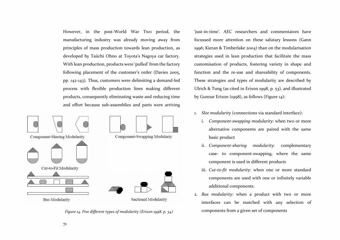
71
However, in the post-World War Two period, the
manufacturing industry was already moving away from
principles of mass production towards lean production, as
developed by Taiichi Ohno at Toyota’s Nagoya car factory.
With lean production, products were ‘pulled’ from the factory
following placement of the customer’s order (Davies 2005,
pp. 142-143). Thus, customers were delimiting a demand-led
process with flexible production lines making different
products, consequently eliminating waste and reducing time
and effort because sub-assemblies and parts were arriving
‘just-in-time’. AEC researchers and commentators have
focussed more attention on these salutary lessons (Gann
1996; Kieran & Timberlake 2004) than on the modularisation
strategies used in lean production that facilitate the mass
customisation of products, fostering variety in shape and
function and the re-use and shareability of components.
These strategies and types of modularity are described by
Ulrich & Tung (as cited in Erixon 1998, p. 53), and illustrated
by Gunnar Erixon (1998), as follows (Figure 14):
1. Slot modularity (connections via standard interface):
i. Component-swapping modularity: when two or more
alternative components are paired with the same
basic product
ii. Component-sharing modularity: complementary
case- to component-swapping, where the same
component is used in different products
iii. Cut-to-fit modularity: when one or more standard
components are used with one or infinitely variable
additional components.
2. Bus modularity: when a product with two or more
interfaces can be matched with any selection of
components from a given set of components Figure 14. Five different types of modularity (Erixon 1998, p. 54)
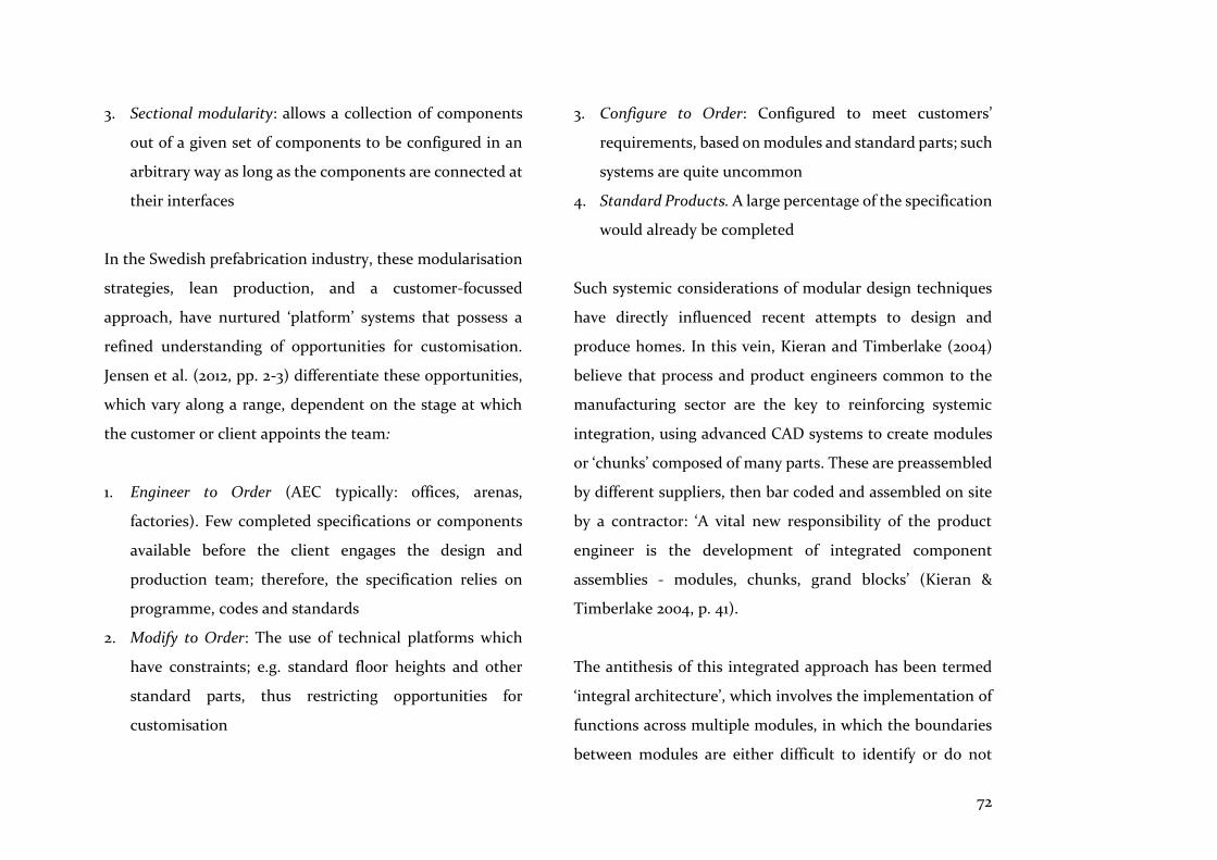
72
3. Sectional modularity: allows a collection of components
out of a given set of components to be configured in an
arbitrary way as long as the components are connected at
their interfaces
In the Swedish prefabrication industry, these modularisation
strategies, lean production, and a customer-focussed
approach, have nurtured ‘platform’ systems that possess a
refined understanding of opportunities for customisation.
Jensen et al. (2012, pp. 2-3) differentiate these opportunities,
which vary along a range, dependent on the stage at which
the customer or client appoints the team:
1. Engineer to Order (AEC typically: offices, arenas,
factories). Few completed specifications or components
available before the client engages the design and
production team; therefore, the specification relies on
programme, codes and standards
2. Modify to Order: The use of technical platforms which
have constraints; e.g. standard floor heights and other
standard parts, thus restricting opportunities for
customisation
3. Configure to Order: Configured to meet customers’
requirements, based on modules and standard parts; such
systems are quite uncommon
4. Standard Products. A large percentage of the specification
would already be completed
Such systemic considerations of modular design techniques
have directly influenced recent attempts to design and
produce homes. In this vein, Kieran and Timberlake (2004)
believe that process and product engineers common to the
manufacturing sector are the key to reinforcing systemic
integration, using advanced CAD systems to create modules
or ‘chunks’ composed of many parts. These are preassembled
by different suppliers, then bar coded and assembled on site
by a contractor: ‘A vital new responsibility of the product
engineer is the development of integrated component
assemblies - modules, chunks, grand blocks’ (Kieran &
Timberlake 2004, p. 41).
The antithesis of this integrated approach has been termed
‘integral architecture’, which involves the implementation of
functions across multiple modules, in which the boundaries
between modules are either difficult to identify or do not
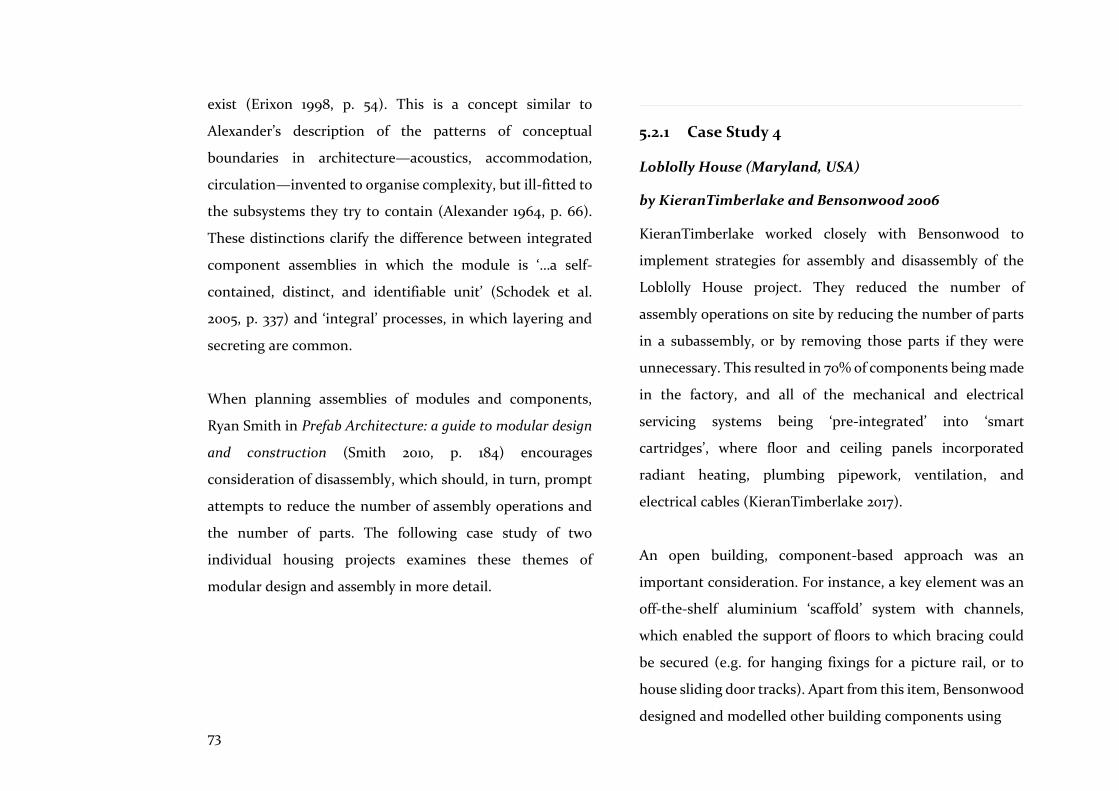
73
exist (Erixon 1998, p. 54). This is a concept similar to
Alexander’s description of the patterns of conceptual
boundaries in architecture—acoustics, accommodation,
circulation—invented to organise complexity, but ill-fitted to
the subsystems they try to contain (Alexander 1964, p. 66).
These distinctions clarify the difference between integrated
component assemblies in which the module is ‘…a self-
contained, distinct, and identifiable unit’ (Schodek et al.
2005, p. 337) and ‘integral’ processes, in which layering and
secreting are common.
When planning assemblies of modules and components,
Ryan Smith in Prefab Architecture: a guide to modular design
and construction (Smith 2010, p. 184) encourages
consideration of disassembly, which should, in turn, prompt
attempts to reduce the number of assembly operations and
the number of parts. The following case study of two
individual housing projects examines these themes of
modular design and assembly in more detail.
5.2.1 Case Study 4
Loblolly House (Maryland, USA)
by KieranTimberlake and Bensonwood 2006
KieranTimberlake worked closely with Bensonwood to
implement strategies for assembly and disassembly of the
Loblolly House project. They reduced the number of
assembly operations on site by reducing the number of parts
in a subassembly, or by removing those parts if they were
unnecessary. This resulted in 70% of components being made
in the factory, and all of the mechanical and electrical
servicing systems being ‘pre-integrated’ into ‘smart
cartridges’, where floor and ceiling panels incorporated
radiant heating, plumbing pipework, ventilation, and
electrical cables (KieranTimberlake 2017).
An open building, component-based approach was an
important consideration. For instance, a key element was an
off-the-shelf aluminium ‘scaffold’ system with channels,
which enabled the support of floors to which bracing could
be secured (e.g. for hanging fixings for a picture rail, or to
house sliding door tracks). Apart from this item, Bensonwood
designed and modelled other building components using
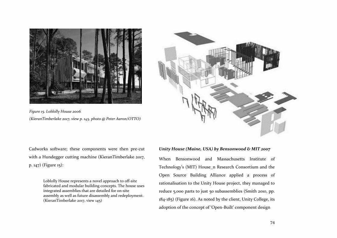
74
Cadworks software; these components were then pre-cut
with a Hundegger cutting machine (KieranTimberlake 2017,
p. 147) (Figure 15):
Loblolly House represents a novel approach to off-site fabricated and modular building concepts. The house uses integrated assemblies that are detailed for on-site assembly as well as future disassembly and redeployment. (KieranTimberlake 2017, view 145)
Unity House (Maine, USA) by Bensonwood & MIT 2007
When Bensonwood and Massachusetts Institute of
Technology’s (MIT) House_n Research Consortium and the
Open Source Building Alliance applied a process of
rationalisation to the Unity House project, they managed to
reduce 5,000 parts to just 50 subassemblies (Smith 2010, pp.
184-185) (Figure 16). As noted by the client, Unity College, its
adoption of the concept of ‘Open-Built’ component design
Figure 15. Loblolly House 2006
(KieranTimberlake 2017, view p. 145, photo @ Peter Aaron/OTTO)
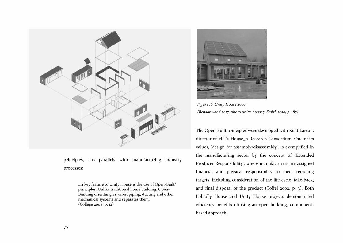
75
principles, has parallels with manufacturing industry
processes:
…a key feature to Unity House is the use of Open-Built® principles. Unlike traditional home building, Open-Building disentangles wires, piping, ducting and other mechanical systems and separates them. (College 2008, p. 14)
The Open-Built principles were developed with Kent Larson,
director of MIT’s House_n Research Consortium. One of its
values, ‘design for assembly/disassembly’, is exemplified in
the manufacturing sector by the concept of ‘Extended
Producer Responsibility’, where manufacturers are assigned
financial and physical responsibility to meet recycling
targets, including consideration of the life-cycle, take-back,
and final disposal of the product (Toffel 2002, p. 3). Both
Loblolly House and Unity House projects demonstrated
efficiency benefits utilising an open building, component-
based approach.
Figure 16. Unity House 2007
(Bensonwood 2017, photo unity-house5; Smith 2010, p. 185)

76
5.3 Prefabrication
…the point is that it is precisely the machine which liberates prefabrication from the slavery of MH [mass housing], and makes prefabrication without MH possible. (Habraken 1999, p. 69)
In a memorandum to the AEG electrical company in 1910,
Walter Gropius defined the principles for mass production of
housing and, when expanding on the notion of a limited
degree of customisation, he proposed that a ‘system of
components’ could be configured in different ways to
respond to customers’ particular requirements (Davies 2005,
p. 132). However, it is only recently that this possibility has
been facilitated with computer-aided manufacturing (CAM),
which dispenses with the need for standardisation, as many
different components can now be made in the same time that
it took to make identical components. According to Davies
(2005, pp. 145-146), dimensional coordination and regulating
grids are no longer necessary.
Although, due to advances in computational technology the
production of information needed to describe and
manipulate different design options is now ‘cheap and easy’
(Kalay 2004, p. 395), in the production of prefabricated
housing, this ability to mass customise information does not
translate viably into an ability to mass customise buildings:
Customer choice that exceeds the limited range is often pushed into a more expensive price bracket for ‘bespoke’ or ‘custom-built’ solutions (Aitchison & Doe 2017, p. 80).
Furthermore, it is argued here that abundance of choice
through on-demand customisation increases the need for
rational procedures that facilitate moderation and regulation
of resource use. Carpo (2011) concurs with this imperative if
the ‘new world’ is to be ideal:
The new world promises seamless, on-demand customization through interactive decision-making, hence - ideally - social responsibility in design, as well as parsimony in the use of natural and human resources. (Carpo 2011, p. 127)
Advancing this argument, it is noted that accurately
dimensioned and parametrically variable coordination is
enhanced when combined with the merits of re-usability and
shareability, concepts indispensable both to computational
design and to prefabrication methods. Perhaps, as Branko
Kolarevic (2009) states, the notion of ‘integrative’, rather than
‘integrated’ design, better captures the digital age’s openness
to collaboration with participants of all persuasions and
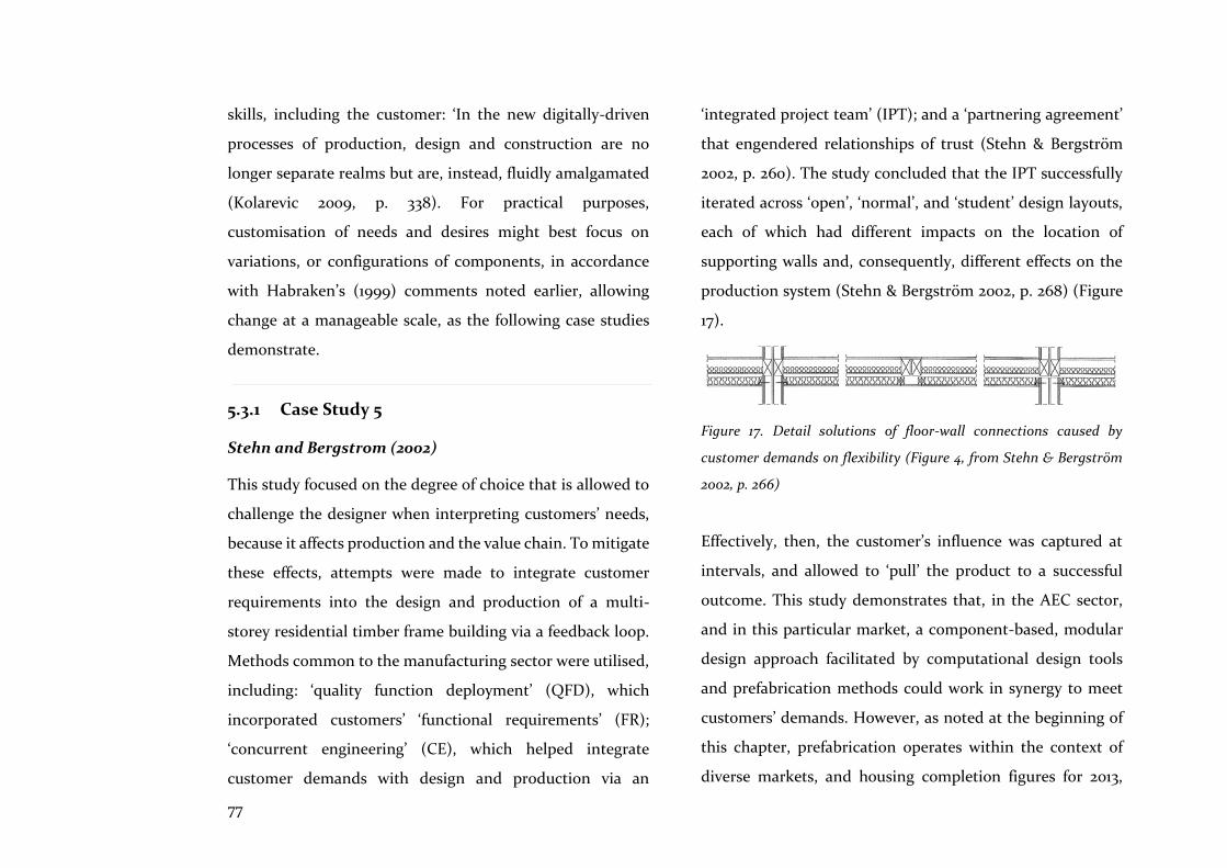
77
skills, including the customer: ‘In the new digitally-driven
processes of production, design and construction are no
longer separate realms but are, instead, fluidly amalgamated
(Kolarevic 2009, p. 338). For practical purposes,
customisation of needs and desires might best focus on
variations, or configurations of components, in accordance
with Habraken’s (1999) comments noted earlier, allowing
change at a manageable scale, as the following case studies
demonstrate.
5.3.1 Case Study 5
Stehn and Bergstrom (2002)
This study focused on the degree of choice that is allowed to
challenge the designer when interpreting customers’ needs,
because it affects production and the value chain. To mitigate
these effects, attempts were made to integrate customer
requirements into the design and production of a multi-
storey residential timber frame building via a feedback loop.
Methods common to the manufacturing sector were utilised,
including: ‘quality function deployment’ (QFD), which
incorporated customers’ ‘functional requirements’ (FR);
‘concurrent engineering’ (CE), which helped integrate
customer demands with design and production via an
‘integrated project team’ (IPT); and a ‘partnering agreement’
that engendered relationships of trust (Stehn & Bergström
2002, p. 260). The study concluded that the IPT successfully
iterated across ‘open’, ‘normal’, and ‘student’ design layouts,
each of which had different impacts on the location of
supporting walls and, consequently, different effects on the
production system (Stehn & Bergström 2002, p. 268) (Figure
17).
Figure 17. Detail solutions of floor-wall connections caused by
customer demands on flexibility (Figure 4, from Stehn & Bergström
2002, p. 266)
Effectively, then, the customer’s influence was captured at
intervals, and allowed to ‘pull’ the product to a successful
outcome. This study demonstrates that, in the AEC sector,
and in this particular market, a component-based, modular
design approach facilitated by computational design tools
and prefabrication methods could work in synergy to meet
customers’ demands. However, as noted at the beginning of
this chapter, prefabrication operates within the context of
diverse markets, and housing completion figures for 2013,

78
collated by Steinhardt et al. (2013, p. 20, Table 6), are
revealing: 12-15% of new homes were prefabricated in Japan,
where homes are considered consumer goods rather than
financial investments, and owners expect to ‘scrap and
rebuild’ approximately every 26 years (Barlow et al. 2003, p.
137); in Sweden, a heritage of prefabricated social housing
programs has seen annual prefabrication rates of 50-90% for
new homes; by contrast, in Australia, dominated by small
business operators, only 5% of homes were prefabricated
(Barlow et al. 2003, p. 137; Steinhardt, Manley & Miller 2013,
p. 20, Table 6).
The example of BoKlok, IKEA and Skanska’s joint venture in
Sweden, is informative in this discussion of markets and
customer expectations: its success is due in part to the sales
experience of IKEA, but primarily because of Skanska’s
understanding and experience of the Swedish housing
market (Aitchison & Doe 2017, p. 136). To increase utilisation
of prefabrication in Australia, Steinhardt et al. (2013, p. 25)
suggest that the following are required:
1. Industry-wide R&D investment
2. Larger markets
3. Skilled workforces
4. Less speculative procurement
5. Multi-residential preferences bringing economies of scale
However, in the absence of these macro level changes,
solutions in Australia need to be pliant and extensible, able
to accommodate change, and able to scale-up when required.
It is argued that the tools and methods discussed—modular
design strategies utilising appropriate computational design
tools - could respond to the flux inherent in such a context.
These methods and tools are examined in a final case study
which examines the effect of customer choice on
modularisation, and the demands it makes on a prefabricated
housing system’s value chain.
5.3.2 Case Study 6
Jensen et al
At Lulea University of Technology (Sweden) Jensen et al.
(2012) worked with Tyrens AB, an AEC consulting company,
to develop a multi-storey residential timber building system,
free-for-use by prospective builders to make parts for
assembly on site. The study focused on a timber floor slab
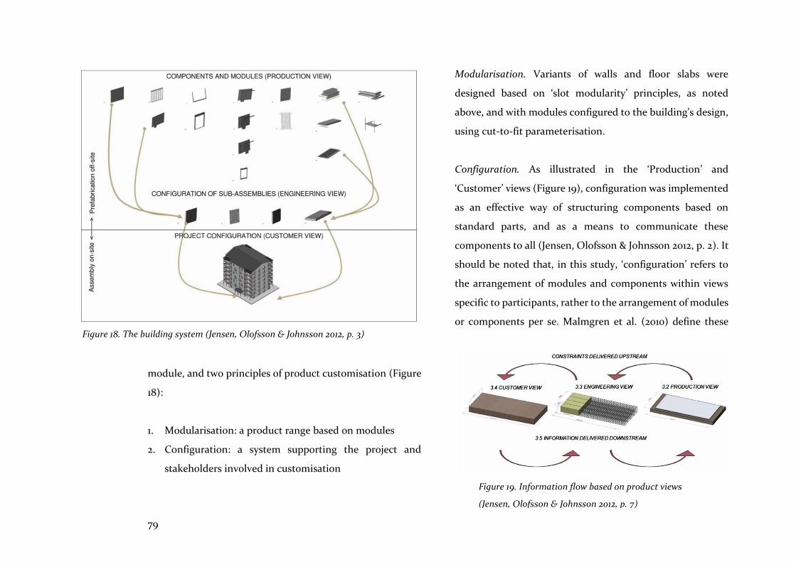
79
module, and two principles of product customisation (Figure
18):
1. Modularisation: a product range based on modules
2. Configuration: a system supporting the project and
stakeholders involved in customisation
Modularisation. Variants of walls and floor slabs were
designed based on ‘slot modularity’ principles, as noted
above, and with modules configured to the building’s design,
using cut-to-fit parameterisation.
Configuration. As illustrated in the ‘Production’ and
‘Customer’ views (Figure 19), configuration was implemented
as an effective way of structuring components based on
standard parts, and as a means to communicate these
components to all (Jensen, Olofsson & Johnsson 2012, p. 2). It
should be noted that, in this study, ‘configuration’ refers to
the arrangement of modules and components within views
specific to participants, rather to the arrangement of modules
or components per se. Malmgren et al. (2010) define these Figure 18. The building system (Jensen, Olofsson & Johnsson 2012, p. 3)
Figure 19. Information flow based on product views
(Jensen, Olofsson & Johnsson 2012, p. 7)
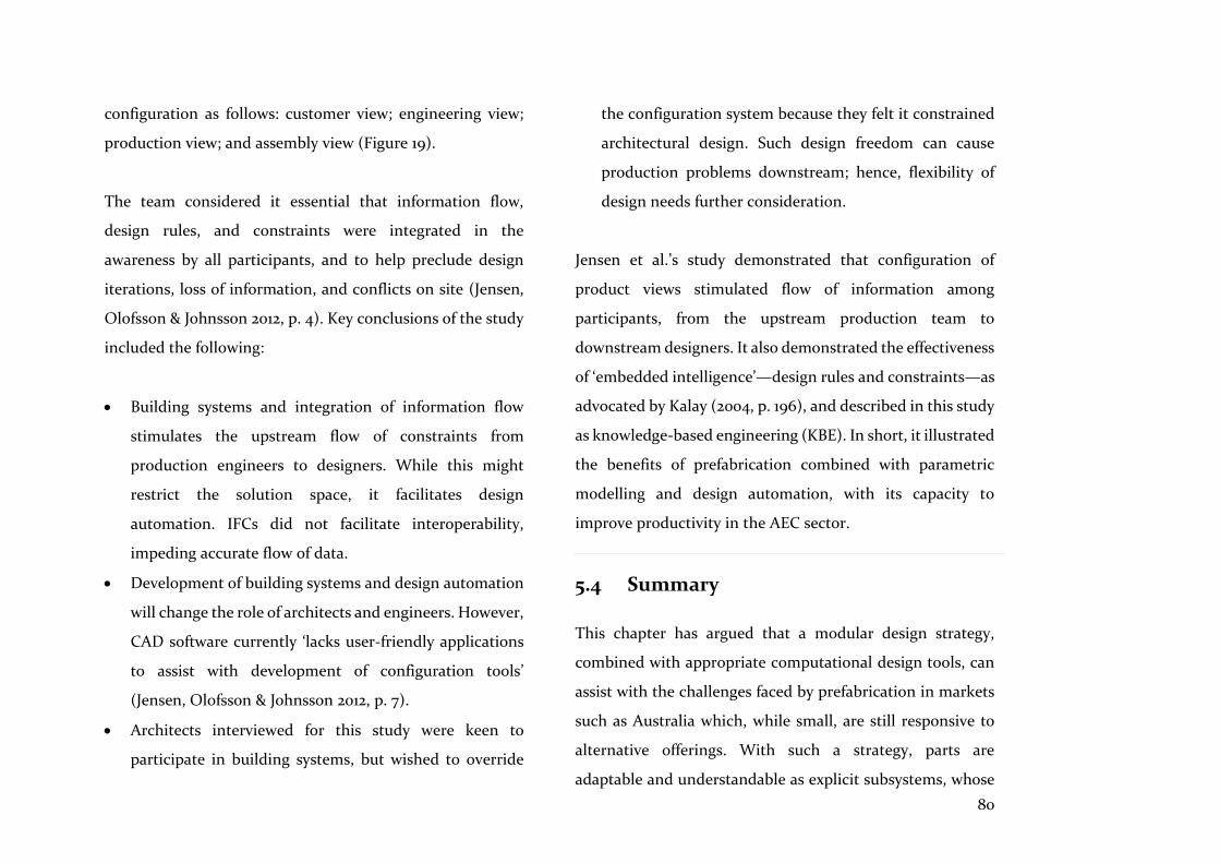
80
configuration as follows: customer view; engineering view;
production view; and assembly view (Figure 19).
The team considered it essential that information flow,
design rules, and constraints were integrated in the
awareness by all participants, and to help preclude design
iterations, loss of information, and conflicts on site (Jensen,
Olofsson & Johnsson 2012, p. 4). Key conclusions of the study
included the following:
• Building systems and integration of information flow
stimulates the upstream flow of constraints from
production engineers to designers. While this might
restrict the solution space, it facilitates design
automation. IFCs did not facilitate interoperability,
impeding accurate flow of data.
• Development of building systems and design automation
will change the role of architects and engineers. However,
CAD software currently ‘lacks user-friendly applications
to assist with development of configuration tools’
(Jensen, Olofsson & Johnsson 2012, p. 7).
• Architects interviewed for this study were keen to
participate in building systems, but wished to override
the configuration system because they felt it constrained
architectural design. Such design freedom can cause
production problems downstream; hence, flexibility of
design needs further consideration.
Jensen et al.’s study demonstrated that configuration of
product views stimulated flow of information among
participants, from the upstream production team to
downstream designers. It also demonstrated the effectiveness
of ‘embedded intelligence’—design rules and constraints—as
advocated by Kalay (2004, p. 196), and described in this study
as knowledge-based engineering (KBE). In short, it illustrated
the benefits of prefabrication combined with parametric
modelling and design automation, with its capacity to
improve productivity in the AEC sector.
5.4 Summary
This chapter has argued that a modular design strategy,
combined with appropriate computational design tools, can
assist with the challenges faced by prefabrication in markets
such as Australia which, while small, are still responsive to
alternative offerings. With such a strategy, parts are
adaptable and understandable as explicit subsystems, whose
81
interactions with other modules can be measured. This is in
contrast to ‘integral’ strategies characterised by on-site
construction, with its layered work sequences which cover up
and conceal.
Dimensional coordination, combined with modular design, is
the foundation for this approach, and techniques for
modularisation have been described as they are used in the
manufacturing sector, and are applicable to AEC projects.
These techniques define distinct and self-contained modules
which may be configured and ‘pulled’ in accordance with
design and production requirements that are shaped by the
customer. This necessitates understanding of upstream
processes and their effect on design outcomes, and a means
to capture changes to these processes, such as an integrated
project team (IPT).
It is also clear that current architectural CAD systems cannot
implement the automated modular design approach
described. Interoperability is a key hindrance, leading to
errors and loss in the exchange of data using IFCs. This is a
significant problem for the AEC sector, as Jensen et al.
comment:
…the implementation of the IFC schema in many commercial applications has been shown to be unreliable, with information being lost or corrupted as a result. (Jensen, Olofsson & Johnsson 2012, p. 3)
One remedy is to use advanced CAD systems for automation
and detailed design tasks which— according to Erixon (1998,
p. 3), KieranTimberlake (2004, p. 41), and Jensen et al.)—
should be implemented by ‘production’ or ‘process’
engineers. However, it is argued here that more user-friendly,
open integrated advanced CAD tools are required to facilitate
architects’ inclusion in a seamless process from conception to
realisation, which includes these tasks. Furthermore,
architects, as key proponents of design intent and customer
requirements, should be fully involved in utilising
configuration systems which are flexible, and which do not
compromise production tasks downstream.
Clearly, prefabrication needs to offer something that site-
constructed homes do not. For the customer, this means a
prefabricated home which is cheaper, faster, and better than
the alternative. It is argued here that prefabrication
incorporating a modular design methodology, when
integrated with appropriate computational design tools, is
the means to offer this alternative.

82
Integrated computational design tools are needed to provide
more certainty that design intentions will be achieved; that
data loss will be reduced; that the re-working of drawings
downstream will be eliminated; that fewer errors will occur;
and that the end result will be what participants and the
client set out to achieve. To realise this integration, and to
meet the needs and expectations of digital age clients and
users, design tools and methods, and the AEC sector itself,
need to be more open, collaborative, interactive, intelligent
and transparent than they presently are.
Project 1 examined the contribution that the computational
design methods and tools of optimisation could make
towards providing better prefabricated home solutions.
Optimisation, with its use of algorithms (components in the
advance towards artificial intelligence), proffers smart
assistance for the designer searching for better solutions—a
search that is central to the design process itself. The
integrated nature of the methods and tools utilised in this
project are examined, and their contribution to improving
prefabricated home design and production are assessed.
6.1 Introduction
Through the use of intricate algorithms, complex computations, and advanced computer systems, designers are able to extend their thoughts into a once unknown and unimaginable world of complexity. (Narahara & Terzidis 2006, p. 423)
Multi-criteria optimisation using a genetic algorithm, as
described in Chapter 4.2, is the method used in this chapter
to implement searches for better environmental performance
of configurations of volumetric homes in the context of a live
case study two standard design variants from two separate
‘module series’ were chosen to demonstrate these analysis
and optimisation processes. For current purposes, these are
termed ‘Type 1’ and ‘Type 2’ (Figures 20 & 21). ‘Volumetric’ or
‘modular’ homes are three-dimensional units that are fitted
out in the factory, and ‘which consist of similar room-sized
units of a size suitable for transportation’ to site (Lawson, M,
Ogden & Goodyear 2014, p. 2).
GAs are seldom used by architectural practices for
optimisation searches to inform their workflow and improve
6 Searching for better
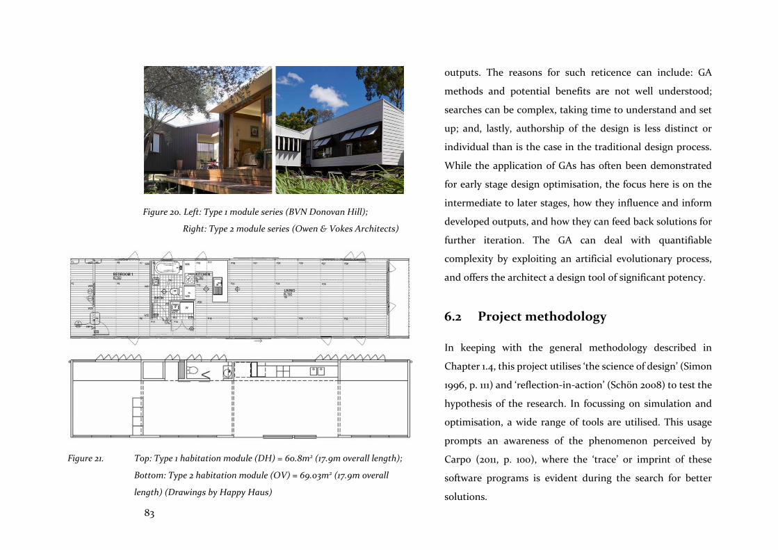
83
outputs. The reasons for such reticence can include: GA
methods and potential benefits are not well understood;
searches can be complex, taking time to understand and set
up; and, lastly, authorship of the design is less distinct or
individual than is the case in the traditional design process.
While the application of GAs has often been demonstrated
for early stage design optimisation, the focus here is on the
intermediate to later stages, how they influence and inform
developed outputs, and how they can feed back solutions for
further iteration. The GA can deal with quantifiable
complexity by exploiting an artificial evolutionary process,
and offers the architect a design tool of significant potency.
6.2 Project methodology
In keeping with the general methodology described in
Chapter 1.4, this project utilises ‘the science of design’ (Simon
1996, p. 111) and ‘reflection-in-action’ (Schön 2008) to test the
hypothesis of the research. In focussing on simulation and
optimisation, a wide range of tools are utilised. This usage
prompts an awareness of the phenomenon perceived by
Carpo (2011, p. 100), where the ‘trace’ or imprint of these
software programs is evident during the search for better
solutions.
Figure 20. Left: Type 1 module series (BVN Donovan Hill);
Right: Type 2 module series (Owen & Vokes Architects)
Figure 21. Top: Type 1 habitation module (DH) = 60.8m2 (17.9m overall length);
Bottom: Type 2 habitation module (OV) = 69.03m2 (17.9m overall
length) (Drawings by Happy Haus)

84
Project 1 was a component of the LP13 ARC Linkage research
study (supported by Queensland Government Accelerate
Partnerships) that examined methods and tools for the
improvement of prefabricated residential modules. It
included industry partners, Happy Haus, Hutchinson
Builders, and BVN Donovan Hill. Happy Haus, based in
Brisbane (Queensland, Australia) is a niche developer
producing several series of architecturally designed modular
homes, suited to both Darwin’s tropical heat and humidity
and Hobart’s temperate coolth. The experiments described
below were carried out from October 2014 to April 2015, and
updated in 2017. Brisbane, with its subtropical climate, was
used as the context for the modular home experiments.
In this investigation of integrated design tools and
production processes, an open integrated system of
parametric and optimisation design tools was employed to
perform multi-criteria optimisation searches, with the aim of
achieving better environmental performance. Tools used
included Rhinoceros, a concept modeller, for creation of
volumetric sleeping and habitation modules and their
configurations; Grasshopper, a visual programming graph
which was linked with the modelled modules to facilitate
environmental analysis and optimisation by genetic
algorithm using the plug-ins Ladybug, Honeybee and
Octopus; EnergyPlus8.1, an environmental simulator which
was linked to Grasshopper; and Excel spreadsheets for
parametric manipulation and visualisation of data. Project 1
comprised three experiments. These were implemented as
follows: either, via Amazon EC2 in a cloud-based
environment to utilise fast and efficient computational
processors – all software was uploaded to Amazon EC2 linked
to EnergyPlus8.1 and optimisations were run from there; or,
on an office-based PC, using software loaded onto its hard-
drive, linked on-line to EnergyPlus8.1.
6.2.1 Multi-criteria optimisation
The art of architecture always engages, at some level, the search for an optimal formal, spatial, constructional answer to diverse aesthetic and performance measures, or a knowing compromise among the above. (Burry, J & Burry 2010, p. 118)
Multi-criteria optimisation involves trade-offs between
interacting performance criteria to find a set of satisfactory
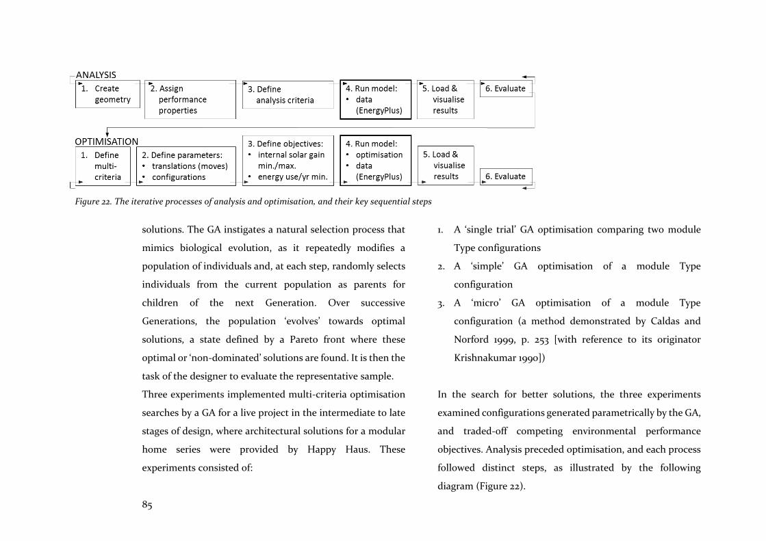
85
solutions. The GA instigates a natural selection process that
mimics biological evolution, as it repeatedly modifies a
population of individuals and, at each step, randomly selects
individuals from the current population as parents for
children of the next Generation. Over successive
Generations, the population ‘evolves’ towards optimal
solutions, a state defined by a Pareto front where these
optimal or ‘non-dominated’ solutions are found. It is then the
task of the designer to evaluate the representative sample.
Three experiments implemented multi-criteria optimisation
searches by a GA for a live project in the intermediate to late
stages of design, where architectural solutions for a modular
home series were provided by Happy Haus. These
experiments consisted of:
1. A ‘single trial’ GA optimisation comparing two module
Type configurations
2. A ‘simple’ GA optimisation of a module Type
configuration
3. A ‘micro’ GA optimisation of a module Type
configuration (a method demonstrated by Caldas and
Norford 1999, p. 253 [with reference to its originator
Krishnakumar 1990])
In the search for better solutions, the three experiments
examined configurations generated parametrically by the GA,
and traded-off competing environmental performance
objectives. Analysis preceded optimisation, and each process
followed distinct steps, as illustrated by the following
diagram (Figure 22).
Figure 22. The iterative processes of analysis and optimisation, and their key sequential steps
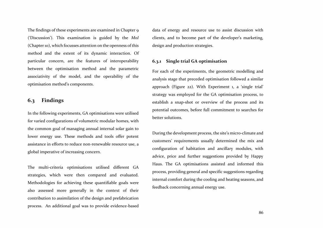
86
The findings of these experiments are examined in Chapter 9
(‘Discussion’). This examination is guided by the MoI
(Chapter 10), which focusses attention on the openness of this
method and the extent of its dynamic interaction. Of
particular concern, are the features of interoperability
between the optimisation method and the parametric
associativity of the model, and the operability of the
optimisation method’s components.
6.3 Findings
In the following experiments, GA optimisations were utilised
for varied configurations of volumetric modular homes, with
the common goal of managing annual internal solar gain to
lower energy use. These methods and tools offer potent
assistance in efforts to reduce non-renewable resource use, a
global imperative of increasing concern.
The multi-criteria optimisations utilised different GA
strategies, which were then compared and evaluated.
Methodologies for achieving these quantifiable goals were
also assessed more generally in the context of their
contribution to assimilation of the design and prefabrication
process. An additional goal was to provide evidence-based
data of energy and resource use to assist discussion with
clients, and to become part of the developer’s marketing,
design and production strategies.
6.3.1 Single trial GA optimisation
For each of the experiments, the geometric modelling and
analysis stage that preceded optimisation followed a similar
approach (Figure 22). With Experiment 1, a ‘single trial’
strategy was employed for the GA optimisation process, to
establish a snap-shot or overview of the process and its
potential outcomes, before full commitment to searches for
better solutions.
During the development process, the site’s micro-climate and
customers’ requirements usually determined the mix and
configuration of habitation and ancillary modules, with
advice, price and further suggestions provided by Happy
Haus. The GA optimisations assisted and informed this
process, providing general and specific suggestions regarding
internal comfort during the cooling and heating seasons, and
feedback concerning annual energy use.
87
Figure 23. Configurations: Type 1 (left), Type 2 (right)
(Drawings by Happy Haus)
Orientation and configurations
The passive solar design principles implemented in this study
defined the orientation of the habitation module and this, in
turn, influenced later choice of optimisation criteria. Hence,
for Brisbane, with a latitude 27.4° in the southern
hemisphere, living spaces should preferably face 20-30°
degrees east of solar north, to maximise solar heat gain in
winter, and to minimise it in summer (McGee, Reardon &
Clarke 2013). Simulation of the habitation module’s
environmental performance was also affected by passive solar
shading devices designed by the architects, and by over-
shadowing of the two sleeping modules. All of these factors
affected the internal solar gain and annual energy use of the
habitation module. Furthermore, the Type 1 habitation
modules had almost equal sized glazing on both sides,
whereas the Type 2 modules had larger areas of glazing on
one long side only (Figure 23).
Creation of geometry
In setting up the geometry, both Type 1 and Type 2’s
volumetric modules were modelled as individual wall and
floor surfaces, and then passed into analysis nodes in the
visual programming graph (Grasshopper). Their habitation
modules were converted into a single enclosed thermal zone,
in which simulated heated and cooled air were to be mixed.
Meanwhile, separate ancillary sleeping modules and all
external shading devices were converted into neutral context
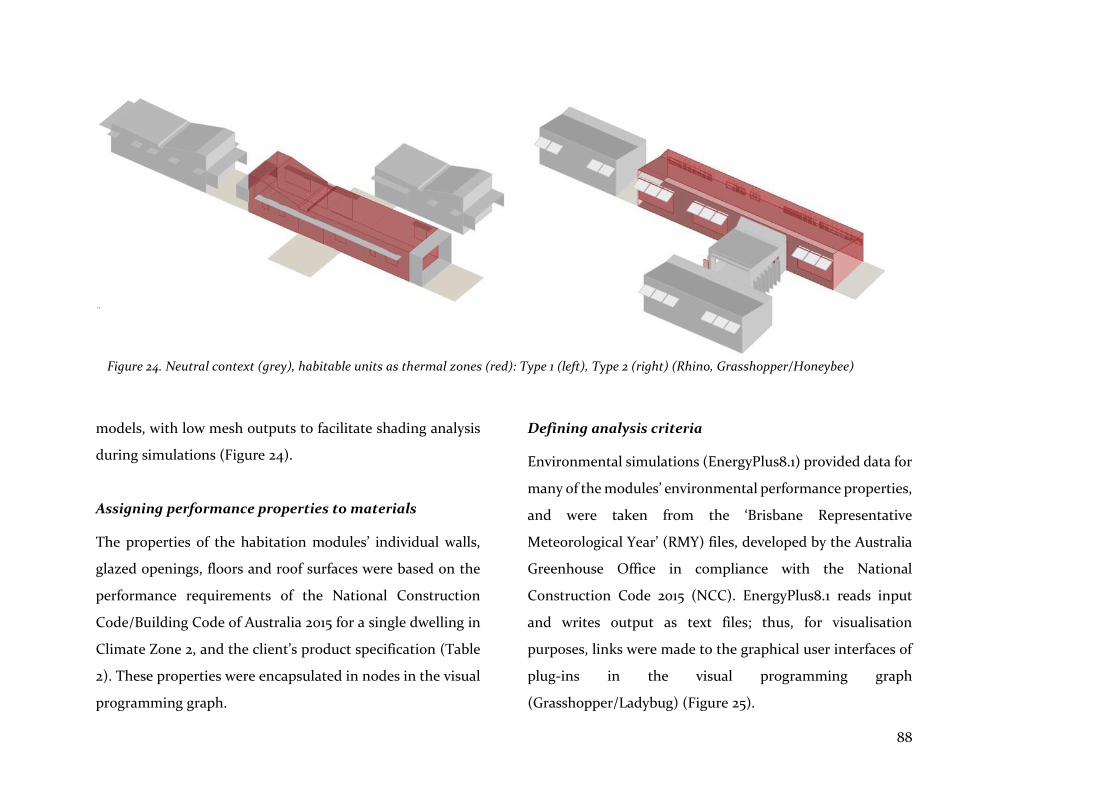
88
models, with low mesh outputs to facilitate shading analysis
during simulations (Figure 24).
Assigning performance properties to materials
The properties of the habitation modules’ individual walls,
glazed openings, floors and roof surfaces were based on the
performance requirements of the National Construction
Code/Building Code of Australia 2015 for a single dwelling in
Climate Zone 2, and the client’s product specification (Table
2). These properties were encapsulated in nodes in the visual
programming graph.
Defining analysis criteria
Environmental simulations (EnergyPlus8.1) provided data for
many of the modules’ environmental performance properties,
and were taken from the ‘Brisbane Representative
Meteorological Year’ (RMY) files, developed by the Australia
Greenhouse Office in compliance with the National
Construction Code 2015 (NCC). EnergyPlus8.1 reads input
and writes output as text files; thus, for visualisation
purposes, links were made to the graphical user interfaces of
plug-ins in the visual programming graph
(Grasshopper/Ladybug) (Figure 25).
Figure 24. Neutral context (grey), habitable units as thermal zones (red): Type 1 (left), Type 2 (right) (Rhino, Grasshopper/Honeybee)

89
Table 2. NCC 2015 R-Values & client’s specification requirements for
windows
Element
R-Value
Walls 2.8
Exposed floor 1.0 upwards
Roof 4.1 downwards
Aluminium framed windows
U-Value 5.5
Solar Heat Gain Coefficient (SHGC) 0.65
Transmittance Value (TVw) 0.65
Figure 25. Environmental simulation data (EnergyPlus8.1): annual
solar data and wind rose October-March, visualised for the Brisbane
(Queensland, Australia) region (Rhino, Grasshopper/Ladybug)
Ventilation, heating and cooling. Environmental management
behaviour would clearly have involved users opening
windows and doors to cool the interior of the residential
modules over the summer season. However, the simulation
tool determined a scenario where inhabitants only made use
of air conditioning while window glazing was fixed in place,
which facilitated simulated calculation of internal solar gain
and energy use. Hence, the fact that cooling breezes were
from the south-east, the fact that the narrow plan of the
modules suited cross-ventilation during summer, and the
reality of user behaviour, were not taken into account, as

90
these factors would have nullified the energy performance
simulations.
Thermal comfort. A measure of thermal comfort was
considered an important check on the effect of internal solar
gains throughout the year. Passive strategies considered in
the thermal comfort analysis included internal heat gain
(from lights, people, etc.), and occupants’ use of fans. These
strategies are shown as overlaid polygons on the
psychrometric chart, their area proportional to their
influence (Figure 26). The thermal comfort node of the visual
programming graph took account of several factors: dry bulb
and mean radiant temperature; internal air speed of 0.5m/s;
occupants’ metabolic rate of 1 met; and clothing levels set to
0.5 clos for summer and 1.5 clos for winter. The measure of
thermal comfort, the Predicted Mean Vote (PMV), was
adjusted by a factor of 0.9 to account for a non-conditioned,
warm-climate, internal environment, as recommended by
Fanger and Toftum (2002, p. 534). However, as noted
previously, a conditioned environment was simulated for
internal solar gain calculations.
Metrics normalised. Internal solar gain and energy use
metrics (kWh) were normalised to the floor area of the
Figure 26. Data from EnergyPlus8.1 to derive annual comfort levels based on PMV (Rhino, Grasshopper/Ladybug)
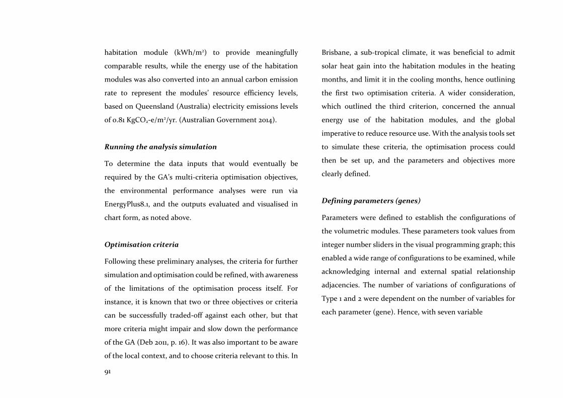
91
habitation module (kWh/m2) to provide meaningfully
comparable results, while the energy use of the habitation
modules was also converted into an annual carbon emission
rate to represent the modules’ resource efficiency levels,
based on Queensland (Australia) electricity emissions levels
of 0.81 KgCO2-e/m2/yr. (Australian Government 2014).
Running the analysis simulation
To determine the data inputs that would eventually be
required by the GA’s multi-criteria optimisation objectives,
the environmental performance analyses were run via
EnergyPlus8.1, and the outputs evaluated and visualised in
chart form, as noted above.
Optimisation criteria
Following these preliminary analyses, the criteria for further
simulation and optimisation could be refined, with awareness
of the limitations of the optimisation process itself. For
instance, it is known that two or three objectives or criteria
can be successfully traded-off against each other, but that
more criteria might impair and slow down the performance
of the GA (Deb 2011, p. 16). It was also important to be aware
of the local context, and to choose criteria relevant to this. In
Brisbane, a sub-tropical climate, it was beneficial to admit
solar heat gain into the habitation modules in the heating
months, and limit it in the cooling months, hence outlining
the first two optimisation criteria. A wider consideration,
which outlined the third criterion, concerned the annual
energy use of the habitation modules, and the global
imperative to reduce resource use. With the analysis tools set
to simulate these criteria, the optimisation process could
then be set up, and the parameters and objectives more
clearly defined.
Defining parameters (genes)
Parameters were defined to establish the configurations of
the volumetric modules. These parameters took values from
integer number sliders in the visual programming graph; this
enabled a wide range of configurations to be examined, while
acknowledging internal and external spatial relationship
adjacencies. The number of variations of configurations of
Type 1 and 2 were dependent on the number of variables for
each parameter (gene). Hence, with seven variable
92
parameters defining a variety of translations and rotations of
the sleeping modules relative to the habitation module, the
2B sleeping module could adopt 24 different positions in
relation to the 1B sleeping module’s 8 positions. As each
sleeping module was also allowed to rotate one step from 0
to 90 degrees, and could slide to one alternative location
relative to the habitation module, the number of
configurations amounted to 768 for Type 1, and 144 for the
Type 2 volumetric modules. Aside from these variable
parameters, fixed parameters included all the habitation and
sleeping modules’ main dimensions, the habitation module’s
glazed window and door dimensions, and the orientation of
all volumetric modules, based on the habitation module’s
longest elevation (which faced 20 degrees east of north, or 70
degrees from the x-axis) in accordance with the passive solar
design principles noted earlier (Figure 27).
Even though narrow adherence to passive solar design
principles - by fixing orientation of all modules—had
restricted the number of configurations that would be
optimised, it became clear that definition of these parameters
could significantly affect the scale of the optimisation
process. However, it was also anticipated that this orientation
tactic would assist evaluation of the effect of shading by the
sleeping modules on the habitation modules. This evaluation
was achieved by limiting the quantity of data outputs for
internal solar gain and energy use criteria provided for
comparison of Type 1 and Type 2 configurations.
Figure 27. Translations & rotations, Type 1: Six of 768 possible configurations (All modules oriented by 700 [north = 900])
93
Defining objectives (phenotype)
Having carefully analysed and considered the criteria for
simulation that were consistent with local climate
characteristics and energy use imperatives, and having set the
parameters, the next step was to set the objectives and
constraints of the optimisation. These objectives and
constraints are detailed below:
• Objective 1: Minimise internal solar gain during
the cooling months (December to February)
• Objective 2: Maximise internal solar gain during
the heating months (June to August)
• Objective 3: Minimise annual energy use (water
heating, heating, cooling, lighting, appliances)
• Constraint 1: Check that, following each
optimisation, comfort levels ranged between Predicted
Mean Vote (PMV) levels of plus or minus 1
As indicated during the analysis phase, Constraint 1 was
introduced with each optimisation, to provide reassurance
that internal solar gain would not impair thermal comfort
levels during the cooling and heating seasons. This constraint
operated as a Boolean true/false regulator, either allowing or
disallowing the optimisation to proceed.
Interface
If the process was to be followed visually, optimisations
required three windows to remain open; however, this was
unnecessary, as evaluations could only occur once the
optimisation process was complete. Typically, the CAD
interface would be minimised to speed up the process, as this
lessened graphics card processing of reiterated screen images
(Figure 28).
Running the optimisation
The fitness values or objectives of individuals that the
simulation engine (EnergyPlus8.1) iteratively supplied, were
optimised by the GA. The population began with 50
individuals, with a crossover rate set to 0.8, and a mutation
rate set to 0.05, which represented the GA’s operators of
reproduction, crossover and mutation. These operators
searched each individual to compute their fitness, relative to
the population of other individuals in the Generation. This
description of the GA’s operators underscores the two

94
Figure 28. Typical user interface (UI): (left to right) CAD (Rhinoceros); GA (Octopus); Visual Programming graph (Grasshopper); (in the background) iterative calls
to the environmental simulation engine (EnergyPlus8.1)

95
separate, yet linked, simulation processes involved: the
iterative calling or accessing of environmental simulation
data, via EnergyPlus8.1; and optimisation of the objectives by
the GA plug-in, simulating artificial evolution and bound by
the operators noted.
Optimisation strategy: ‘single trial’
While drawing concrete conclusions from a single trial of a stochastic process is, at best, a risky business, we start to see how genetic algorithms combine high-performance notions to achieve better performance. (Goldberg 1989, p. 16)
The run-time for optimisation of each individual was
dependent on several factors: the variable number of
individuals or module configurations; the size of the initial
population; and the number of Generations the GA would
optimise. A population of 50 and 1 Generation was estimated
to take 1.5 hours if all individuals were each optimised in 55
seconds, a time contingent on the iterative accessing and
returning of data from the simulation engine (EnergyPlus8.1).
Amazon EC2’s efficient and fast on-line processors resulted
in individual optimisation times similar to the time taken on
an office-based PC; therefore, they were ineffectual in
speeding up this process of iterative calling to the simulation
engine. At this stage, a quick optimisation search was needed
to provide an overview of results and the process. Thus, an
optimisation strategy that involved searching across a single
Generation of a maximum of 100 individuals (population x 2)
- to limit run-time and create a snap-shot of the optimisation
process as a whole - was implemented. While this was not a
strategy that would provide accurate conclusions, it was
anticipated that this ‘single trial of a stochastic process’ would
assist in understanding the optimisation process itself, and its
effectiveness in achieving better solutions (Goldberg 1989, p.
16). The ‘single trial’ strategy was also expected to aid
understanding of the operability and utility of the
methodology.
Hence, two optimisation runs were implemented to compare
Type 1 and Type 2 volumetric module configurations. Type 1
had an initial population of 50 individuals, which was
reproduced to 100, yielding 14 Pareto front individuals. Type
2, on the other hand, had an initial population of 25
individuals, reproduced to 50, and yielding 10 Pareto front
individuals for further evaluation (Table 3). Type 1’s
optimisation run took approximately 1 hr 40 mins to
complete, while Type 2’s took half this time.

96
Table 3. Pareto front (optimal) and elite solutions: Type 1 (dh) and Type 2 (ov), Brisbane (Queensland, Australia); (27.4S, 153.1E)
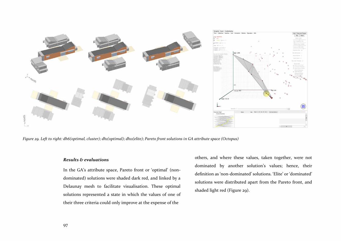
97
Results & evaluations
In the GA’s attribute space, Pareto front or ‘optimal’ (non-
dominated) solutions were shaded dark red, and linked by a
Delaunay mesh to facilitate visualisation. These optimal
solutions represented a state in which the values of one of
their three criteria could only improve at the expense of the
others, and where these values, taken together, were not
dominated by another solution’s values; hence, their
definition as ‘non-dominated’ solutions. ‘Elite’ or ‘dominated’
solutions were distributed apart from the Pareto front, and
shaded light red (Figure 29).
Figure 29. Left to right: dh6(optimal, cluster); dh1(optimal); dh11(elite); Pareto front solutions in GA attribute space (Octopus)
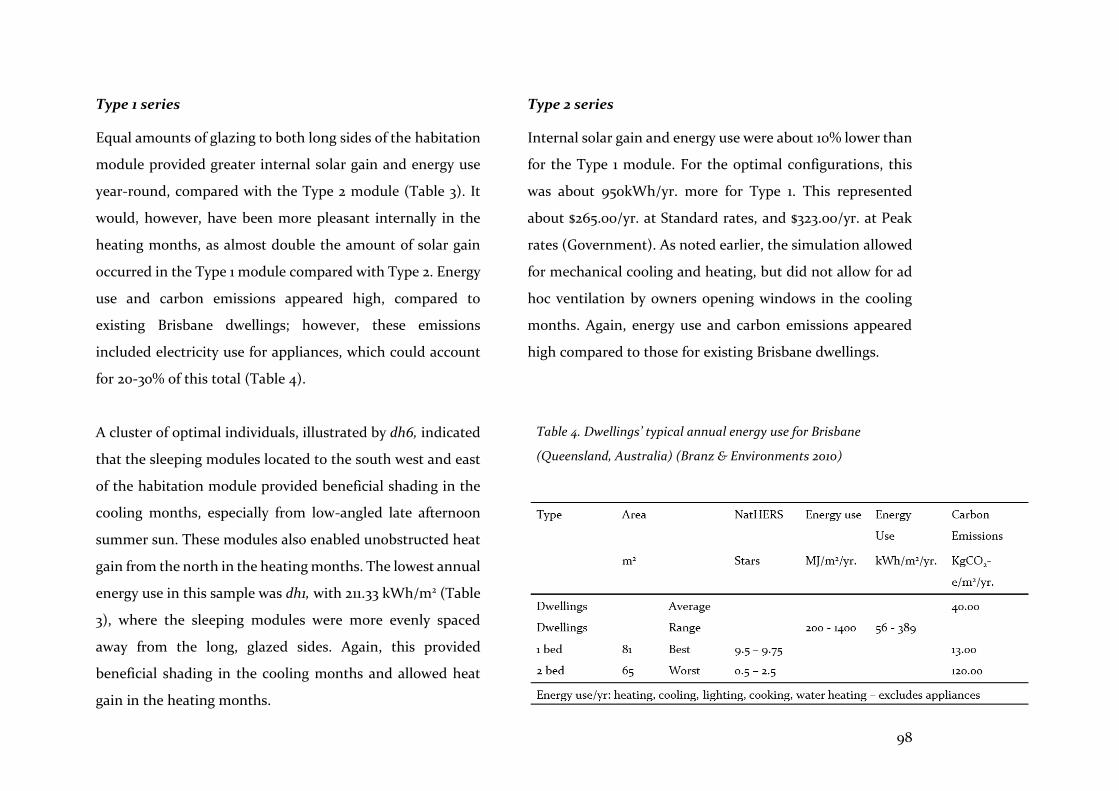
98
Type 1 series
Equal amounts of glazing to both long sides of the habitation
module provided greater internal solar gain and energy use
year-round, compared with the Type 2 module (Table 3). It
would, however, have been more pleasant internally in the
heating months, as almost double the amount of solar gain
occurred in the Type 1 module compared with Type 2. Energy
use and carbon emissions appeared high, compared to
existing Brisbane dwellings; however, these emissions
included electricity use for appliances, which could account
for 20-30% of this total (Table 4).
A cluster of optimal individuals, illustrated by dh6, indicated
that the sleeping modules located to the south west and east
of the habitation module provided beneficial shading in the
cooling months, especially from low-angled late afternoon
summer sun. These modules also enabled unobstructed heat
gain from the north in the heating months. The lowest annual
energy use in this sample was dh1, with 211.33 kWh/m2 (Table
3), where the sleeping modules were more evenly spaced
away from the long, glazed sides. Again, this provided
beneficial shading in the cooling months and allowed heat
gain in the heating months.
Type 2 series
Internal solar gain and energy use were about 10% lower than
for the Type 1 module. For the optimal configurations, this
was about 950kWh/yr. more for Type 1. This represented
about $265.00/yr. at Standard rates, and $323.00/yr. at Peak
rates (Government). As noted earlier, the simulation allowed
for mechanical cooling and heating, but did not allow for ad
hoc ventilation by owners opening windows in the cooling
months. Again, energy use and carbon emissions appeared
high compared to those for existing Brisbane dwellings.
Table 4. Dwellings’ typical annual energy use for Brisbane
(Queensland, Australia) (Branz & Environments 2010)

99
However, as with Type 1, they included electricity use for
appliances, and this could account for 20-30% of this total
(Table 3, Figure 30).
A cluster of individuals illustrated by ov2 indicated a
configuration that allowed low-angle winter sun to penetrate
adequately, albeit obstructing low-angle, early and late
afternoon sun in the summer. The least internal solar gain in
summer, and in energy use annually, was achieved by ov1, at
3.11 kWh/m2 and 194.40 kWh/m2 respectively. However, of all
the optimal solutions evaluated, ov1 achieved the least
internal solar gain in winter. A surprise was ov8, which not
only gave very low energy use and low heat gain in summer,
at 194.67 kWh/m and 3.14 kWh/m2 respectively, but also low
heat gain in winter. This might have been an option that a
customer was happy with, and the evaluation illustrated the
nature of this decision-making process, which is about trade-
offs rather than finding the best of all solutions.
Figure 30. Left to right: ov1(optimal); ov2(optimal, cluster); ov7(optimal); Pareto front solutions in GA attribute space (Octopus)
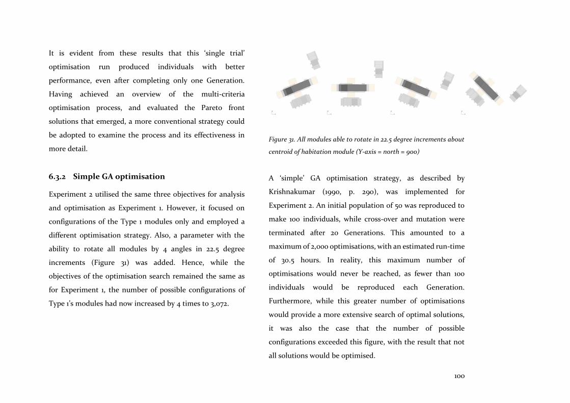
100
It is evident from these results that this ‘single trial’
optimisation run produced individuals with better
performance, even after completing only one Generation.
Having achieved an overview of the multi-criteria
optimisation process, and evaluated the Pareto front
solutions that emerged, a more conventional strategy could
be adopted to examine the process and its effectiveness in
more detail.
6.3.2 Simple GA optimisation
Experiment 2 utilised the same three objectives for analysis
and optimisation as Experiment 1. However, it focused on
configurations of the Type 1 modules only and employed a
different optimisation strategy. Also, a parameter with the
ability to rotate all modules by 4 angles in 22.5 degree
increments (Figure 31) was added. Hence, while the
objectives of the optimisation search remained the same as
for Experiment 1, the number of possible configurations of
Type 1’s modules had now increased by 4 times to 3,072.
Figure 31. All modules able to rotate in 22.5 degree increments about
centroid of habitation module (Y-axis = north = 90o)
A ‘simple’ GA optimisation strategy, as described by
Krishnakumar (1990, p. 290), was implemented for
Experiment 2. An initial population of 50 was reproduced to
make 100 individuals, while cross-over and mutation were
terminated after 20 Generations. This amounted to a
maximum of 2,000 optimisations, with an estimated run-time
of 30.5 hours. In reality, this maximum number of
optimisations would never be reached, as fewer than 100
individuals would be reproduced each Generation.
Furthermore, while this greater number of optimisations
would provide a more extensive search of optimal solutions,
it was also the case that the number of possible
configurations exceeded this figure, with the result that not
all solutions would be optimised.
101
Evaluations
Optimisation searches were carried out via a PC and left to
run during the day and overnight. A considerable amount of
data was generated, necessitating a more sophisticated
evaluation process than was the case for Experiment 1. As
visual evaluations of individuals’ models and related data
outputs were ineffectual, data was transferred to Excel
spreadsheets to facilitate observation from the 1st Generation
to the last, thus indicating improvements to individuals’
objectives over time. Consequently, the chart below
compares the difference between 40 solutions for Generation
1 and Generation 19’s three objectives. This confirmed that
better solutions had evolved over time: the preponderance of
bars to the left of zero indicate overall reductions in kWh/m2
for internal solar gain in the heating and cooling seasons
(negative kWh/m2 results normalised for comparison), and
for annual energy use (Figure 32).
In Generation 1, the optimisation search provided 49 optimal
solutions and, by Generation 20, it had provided 78 for
evaluation. Analysis periods differed slightly between
Experiment 1 and 2: the former analysed cooling and heating
seasons from December-February and from June-August,
while the latter analysed January-March and May-July. This
explained why the kWh figures for Objective 1 and 2’s internal
solar gain differed during the cooling and heating months.
However, values for Objective 3 (minimisation of annual
energy use) could be compared directly between Experiment
1 and 2 for the Type 1 module configurations. The chart below
indicates the improvement of these values for 9 optimal
solutions (Figure 33).

102
Figure 32. Experiment 2: Generation 19 objectives minus Generation 1 objectives, indicates change over time for 40 Pareto front solutions (units kWh/m2)
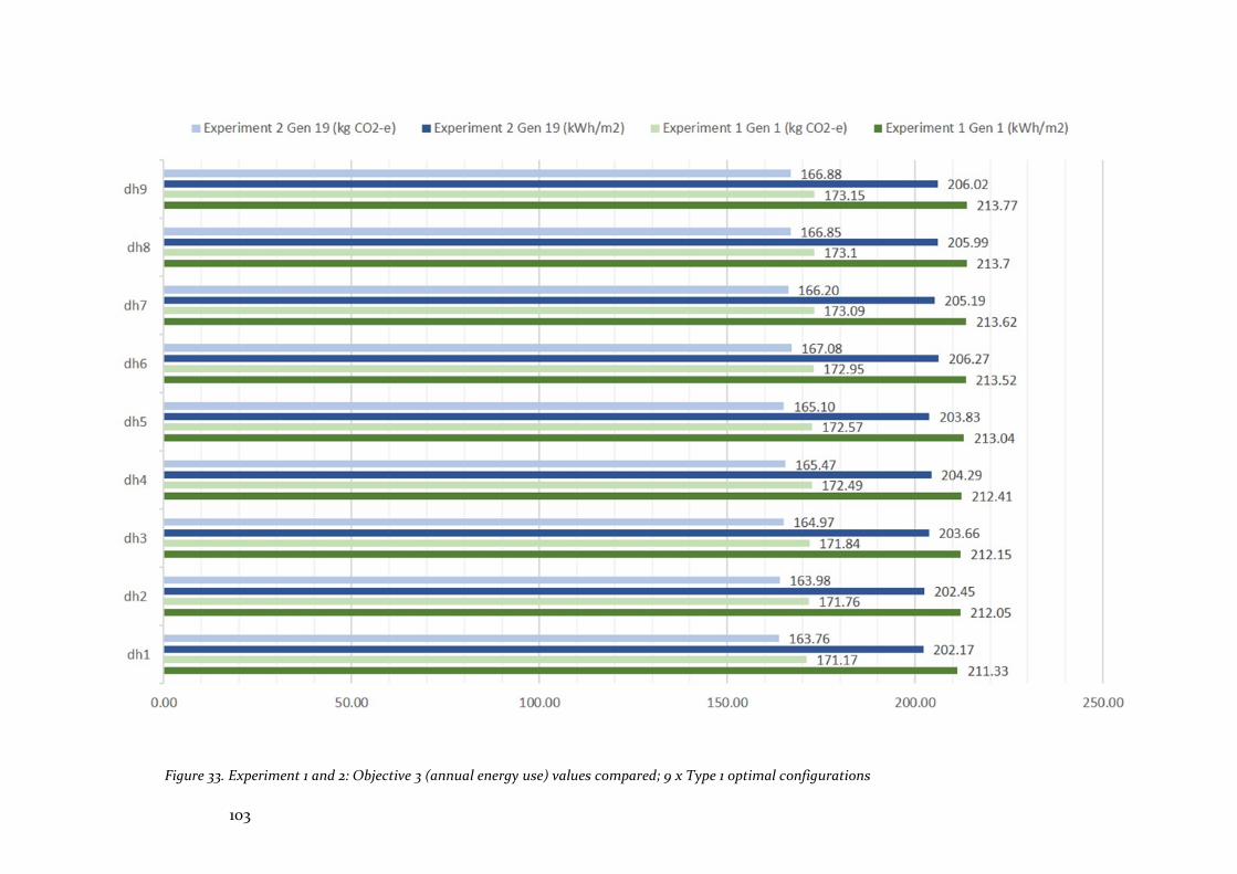
103
Figure 33. Experiment 1 and 2: Objective 3 (annual energy use) values compared; 9 x Type 1 optimal configurations
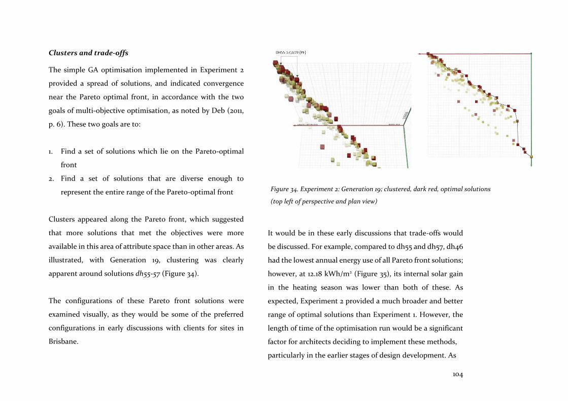
104
Clusters and trade-offs
The simple GA optimisation implemented in Experiment 2
provided a spread of solutions, and indicated convergence
near the Pareto optimal front, in accordance with the two
goals of multi-objective optimisation, as noted by Deb (2011,
p. 6). These two goals are to:
1. Find a set of solutions which lie on the Pareto-optimal
front
2. Find a set of solutions that are diverse enough to
represent the entire range of the Pareto-optimal front
Clusters appeared along the Pareto front, which suggested
that more solutions that met the objectives were more
available in this area of attribute space than in other areas. As
illustrated, with Generation 19, clustering was clearly
apparent around solutions dh55-57 (Figure 34).
The configurations of these Pareto front solutions were
examined visually, as they would be some of the preferred
configurations in early discussions with clients for sites in
Brisbane.
It would be in these early discussions that trade-offs would
be discussed. For example, compared to dh55 and dh57, dh46
had the lowest annual energy use of all Pareto front solutions;
however, at 12.18 kWh/m2 (Figure 35), its internal solar gain
in the heating season was lower than both of these. As
expected, Experiment 2 provided a much broader and better
range of optimal solutions than Experiment 1. However, the
length of time of the optimisation run would be a significant
factor for architects deciding to implement these methods,
particularly in the earlier stages of design development. As
Figure 34. Experiment 2: Generation 19; clustered, dark red, optimal solutions
(top left of perspective and plan view)
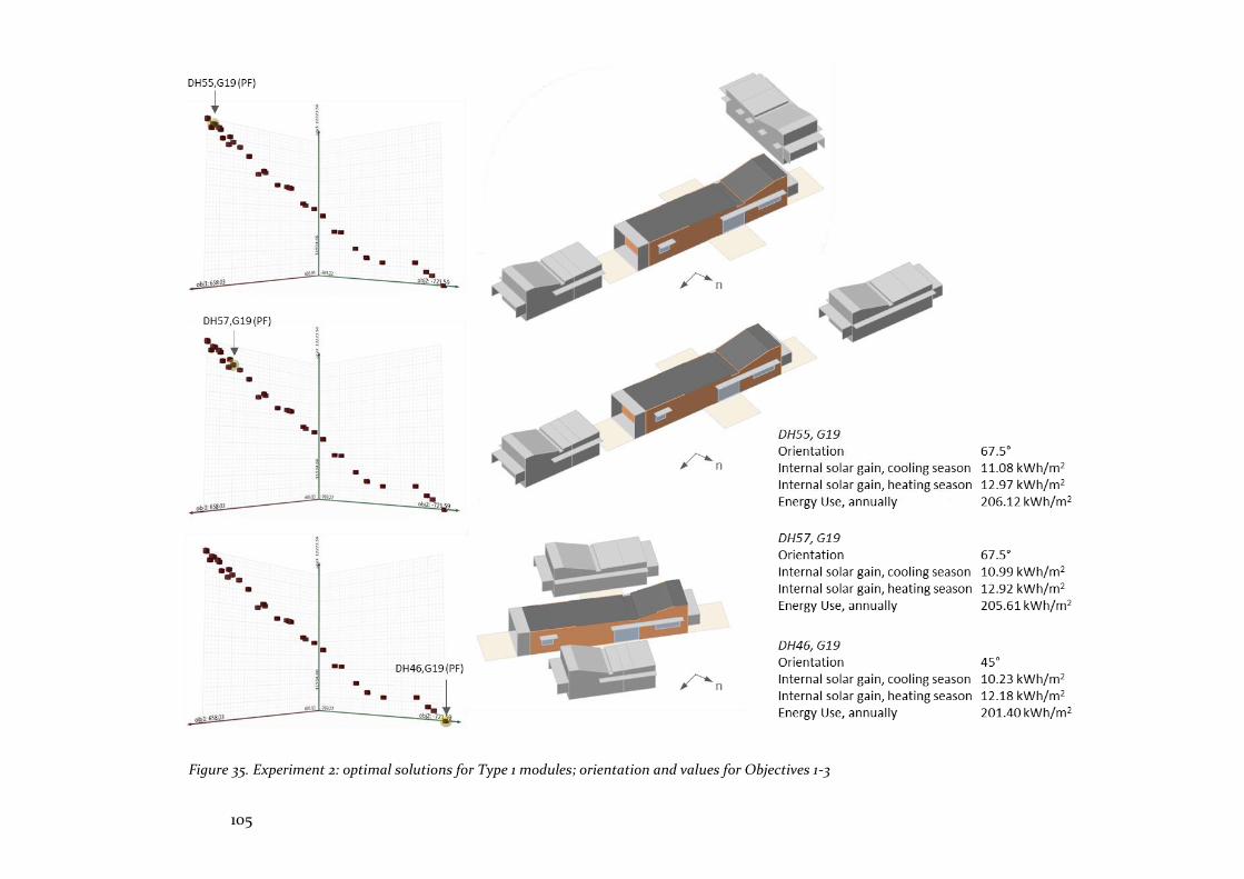
105
Figure 35. Experiment 2: optimal solutions for Type 1 modules; orientation and values for Objectives 1-3

106
with set up of the design domain described in Chapter 3, set
up and implementation of the GA optimisation process
placed distance in time and space between the researcher and
the design task. Therefore, the intention with Experiment 3
was to examine a method for reducing this distance.
6.3.3 Micro GA optimisation
…our performance measure for μGA [micro GA] should be based on the best-so-far string, rather than on any average performance. (Krishnakumar 1990, p. 291)
Experiment 3 also utilised the same three objectives for
analysis and optimisation as Experiment 2, and focused on
configurations of the Type 1 modules. However, it employed
an optimisation strategy which would provide quicker results
early on in the optimisation run.
Optimisation strategy - ‘micro’
For Experiment 3, a ‘micro’ GA (μGA ) optimisation strategy
devised by Krishnakumar (1990, p. 291), and based on the
work of Goldberg (1988), was implemented. It began with a
very low population of only 5 individuals. The purpose was to
find an optimum solution quickly, rather than to find the
average of a population of individuals. GA settings that
influenced this included a cross-over rate of 1.0, and a
mutation rate set to 0.0. Once a population had been
optimised, a new random population was generated, while
carrying over the best or elite individual from the previous
generation, as intended by the SPEA2 algorithm utilised by
the plug-in (Octopus). Even though the generation rate was
set to 100, the optimisation run behaved differently to the
previous strategy, as solutions converged early on around
Generation 20, after which few changes occurred. If 1,000
solutions had been optimised, the run-time should have been
12.5 hours; rather, because the population was small and
convergence occurred early, it was much quicker, taking
approximately 2.5 hours to complete.
Evaluations
In general, the micro GA performed well, as it found high
performance solutions close to the global minimum for the
three objectives optimised. In contrast, and as noted in
Chapter 4.2, a search of the ‘local’ minimum might have given
a distorted overall view. As already mentioned, Holland
(1992, p. 2) suggested that similar results would be found
should blind men examine an elephant by contact alone.
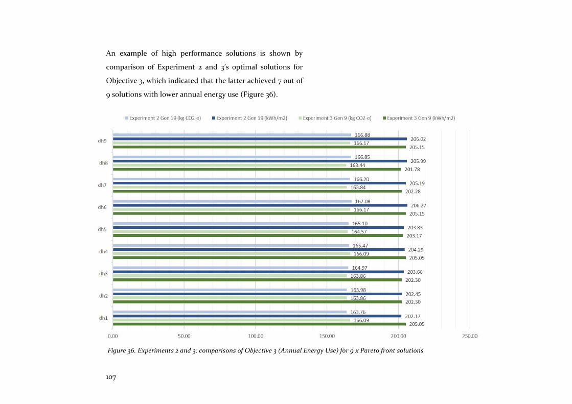
107
An example of high performance solutions is shown by
comparison of Experiment 2 and 3’s optimal solutions for
Objective 3, which indicated that the latter achieved 7 out of
9 solutions with lower annual energy use (Figure 36).
Figure 36. Experiments 2 and 3: comparisons of Objective 3 (Annual Energy Use) for 9 x Pareto front solutions
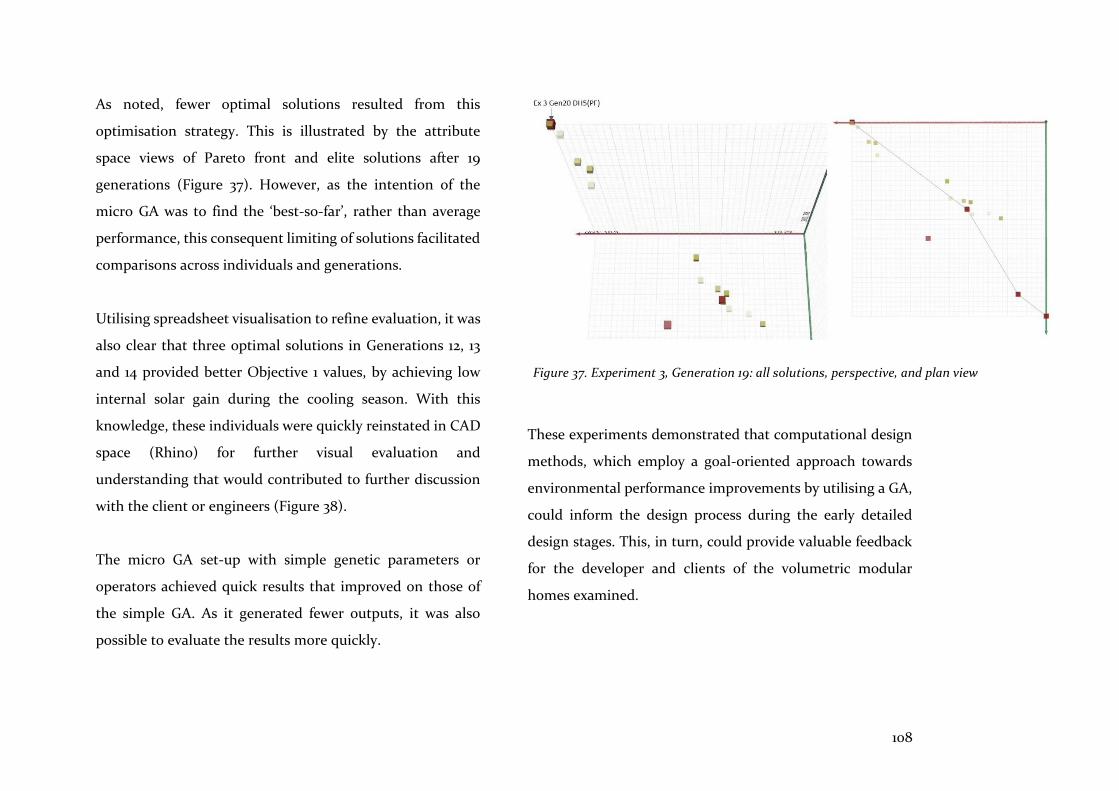
108
As noted, fewer optimal solutions resulted from this
optimisation strategy. This is illustrated by the attribute
space views of Pareto front and elite solutions after 19
generations (Figure 37). However, as the intention of the
micro GA was to find the ‘best-so-far’, rather than average
performance, this consequent limiting of solutions facilitated
comparisons across individuals and generations.
Utilising spreadsheet visualisation to refine evaluation, it was
also clear that three optimal solutions in Generations 12, 13
and 14 provided better Objective 1 values, by achieving low
internal solar gain during the cooling season. With this
knowledge, these individuals were quickly reinstated in CAD
space (Rhino) for further visual evaluation and
understanding that would contributed to further discussion
with the client or engineers (Figure 38).
The micro GA set-up with simple genetic parameters or
operators achieved quick results that improved on those of
the simple GA. As it generated fewer outputs, it was also
possible to evaluate the results more quickly.
These experiments demonstrated that computational design
methods, which employ a goal-oriented approach towards
environmental performance improvements by utilising a GA,
could inform the design process during the early detailed
design stages. This, in turn, could provide valuable feedback
for the developer and clients of the volumetric modular
homes examined.
Figure 37. Experiment 3, Generation 19: all solutions, perspective, and plan view
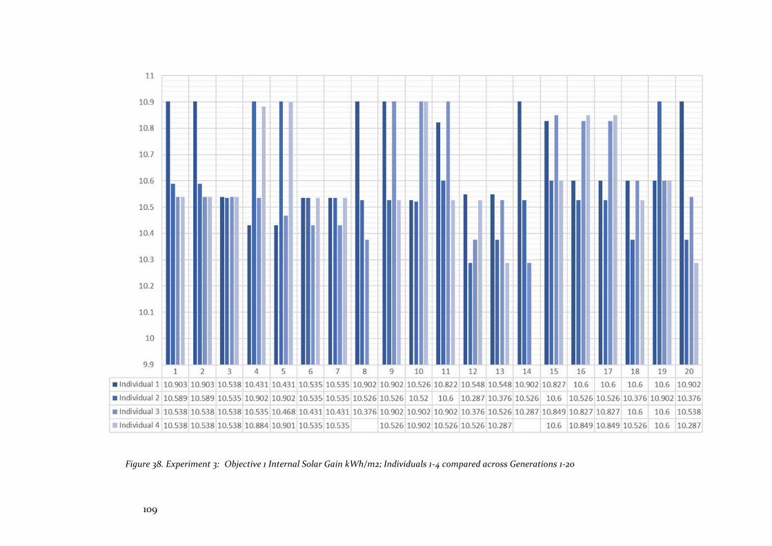
109
Figure 38. Experiment 3: Objective 1 Internal Solar Gain kWh/m2; Individuals 1-4 compared across Generations 1-20
110
6.4 Summary
The three experiments in Project 1 adapted optimisation to a
top-down design problem. As the volumetric modules had
already been designed (by Happy Haus architects), questions
that remained open concerned the configuration of the
client’s modules on site, based on environmental or
functional performance. Therefore, as noted in the
introduction to this thesis, one of the goals of these
experiments was to assist discussion with clients, and to
provide evidence-based energy and resource usage data that
could become part of the developer’s marketing, design and
production strategies.
The first experiment focused on a ‘single trial GA’
optimisation that provided an overview of the process and its
potential outcomes. Detailed analysis of the environmental
conditions enabled clear definition of the relevant objectives
that defined the technical goals of the optimisation search.
This definition highlighted differences between parameters
that could influence the model, and parameters that were
intrinsic to the GA utilised. Set up of the optimisation process
was a lengthy exercise, involving a moderate degree of
cognitive stress when creating the logical imperatives of the
visual programming graph. Once set up, it became clear that
the run-time of the optimisation searches would be a
significant factor affecting architects’ utility and ease-of-use
of the tool.
The second experiment, using a ‘simple GA’ optimisation,
employed a more thorough search of the solution space.
While this took much more time to reach completion, it
provided better solutions than the ‘single trial’. The results
required more sophisticated analysis and evaluation
techniques, using spreadsheets. However, it was clear that
the algorithmic set-up, and the time taken to search
solutions, placed distance between the researcher, the design
intent, and the design solutions.
The third experiment, using a ‘micro GA’ optimisation,
attempted to mitigate some of the problems identified above.
This optimisation strategy was quicker and provided
improved solutions compared with the ‘simple GA’. Fewer
outputs and, therefore, a reduced quantity of data results
enabled evaluations to be processed more quickly.

111
The three experiments utilised ‘intelligent’ strategies to assist
the architect when searching for better design solutions. This
contribution by the computational design tool advances
attempts to provide architects with tools that are adjuncts to
the design process. The optimisation process itself also
closely reflects the way that architects operate because, as
Goldberg (1989, p. 22) observes, they ‘connect to our own
ideas of human search or discovery’. Accordingly, Simon
likens optimisation to the declarative logic ‘designers use
when they are being careful about their reasoning’ (Simon
1996, p. 115), which is consistent with Mitchell’s (1989, p. 8)
advocation of the declarative format as a better
representation of design rules, as noted in Chapter 3.2.3.
Integration of computational design tools that improve
production—and prefabrication in particular—in the AEC
sector, requires tools that improve interoperability and
interaction among participants. To be effective, the GA that
was implemented for Project 1 demands close interoperability
of methods and systems, while interaction among
participants is central to ensuring that relevant criteria are
examined so that search outputs are relevant and meaningful.
These discussion points, and the findings of the experiments
in Project 1, are examined in more detail in Chapter 9
(‘Discussion’). There, the MoI is used to assess the features
and attributes of these tools. In Chapter 10 (‘Integrated
Modelling’), it is used to evaluate the degree of integration
that such tools and methods provide.
112
This project examined set up of the computationally designed
model, beginning at the design development stage, where
schematic ideas, analogue sketches and CAD models progress
to a more complete organisation of the whole. This research
argues that this moment of set up is the main impediment to
a seamless transition from the concept stage to project
realisation, because of the lack of integrated computational
design tools that are able to facilitate this transition. An
architect should be able to model a component with the
understanding that it represents something realisable, and
that it is not merely a virtual construction determined by the
software tool rather than by the exigencies of production.
Correspondingly, improvements to prefabricated homes will
only occur when tools and methods facilitate such
authenticity; that is, when they are able to contribute to
downstream flows of accurate information from designers
and clients, and can respond effectively to upstream flows of
data from engineers and fabricators.
7.1 Introduction
Set up is investigated with reference to the ‘design domain’,
the framework that creates better understanding of the
structure of the artefact being designed, and the topological
space of relations abstracted from geometrical content
(Burry, J 2007, p. 615). Paradoxically, this framework confers
the benefit of distance between designer and artefact,
allowing the deferral of design decisions, and emerging as an
expanded cognitive design space, open for exploration by
students and architects (Burry, J 2007, p. 622). This opening
move benefits from prefabricated design workflows because
they are front-loaded, thus bringing forward the flow of data
and information that supports set up of the design domain.
This chapter also examines the format in which design rules
for set up of the model are expressed. As noted in Chapter
3.2.3, design rules are a computational expression of a
procedure, delineating design requirements as input, and the
result as output. Mitchell (1989, p. 8) argues that they should
be expressed in a ‘declarative’ and ‘modular’ programming
format. The focus of Project 2 is to examine design rules in
the modular format.
In the programming context, a modular format denotes
discrete input and output parameters that comprise ‘self-
contained chunks of code’, allowing modules to be shared, re-
used, and debugged at modular level (Davis, Burry & Burry
7 Generation & set up
113
2011, p. 58). However, because modularity (as discussed in
Chapter 5) assists with the comprehension of all complex
artificial systems, the concept of the modular format is
extensible, relating to programming, computational design,
and to prefabrication methods. Examples of the principles of
modularity used in prefabricated home design and
production were described in Chapter 5.2, and will be
examined later in Project 3 (Chapter 8). Meanwhile, the focus
in this Chapter is the notion of the modular format and its
compatibility with programming, computational design, and
prefabrication methods.
7.2 Project methodology
Developing the general methodology described in Chapter
1.3, this project further demonstrates the process of
‘reflection-in-action’ (Schön 2008) to test the hypothesis of
the research. Integration necessitates a commitment to
methods and tools that foster interoperability of participants,
and that emphasise these tools operability. When focussing
on generation and set up a variety of tools were employed to
implement the computational design methods described
above, for the purpose of improving prefabricated home
design. Autodesk Revit, an AEC CAD tool, was used to
examine its Family type’s ability to create modular
components; these Family types were linked to Autodesk
Dynamo, a visual programming graph, to examine its ability
to automatically place and manipulate these types; for
comparison, Digital Project, an advanced CAD tool, was used
to examine its hierarchically organised, parametric, solid-
modelling approach when creating modular components.

114
Project 2 and Project 3 were adjuncts to the AP14 research
case study supported by Queensland Government Accelerate
Partnerships (2014 to 2016), which compared prefabricated
assembly with traditional building methods in the design of
a three-storey residential building in Brisbane (Queensland,
Australia). It developed a hybrid prefabrication strategy
comprising: panellisation of cross-laminated timber (CLT)
walls, floors, and roofs; the volumetric design of bathroom
and storage pods using light gauge steel (LGS) members; and
CLT clip-on balcony assemblies (Figure 39). Project 2 was
carried out from May to September 2016, and was updated in
2017.
Figure 39. AP14 case study: unit plans (top left); whole scheme in axonometric (top right);
assembly studies (bottom) (Autodesk Revit)
115
7.2.1 Design domain
The advantages and disadvantages arising from set up of the
framework of the design domain were assessed, as follows:
1. Distance created by set up of the abstract rules that define
the design domain. Jane Burry describes the design
domain’s framework as a topological rather than a
geometrical representation of design intent, which may
be ‘inhibitory’ to the further investigation of ideas (Burry,
J 2007, p. 622). This framework, an abstract
representation of geometrical form, requires shared
knowledge of the properties of the representation to be
understood by participants, as Kalay notes (Kalay 2004,
pp. 87-88).
2. Deferral, allowed by the distance created. Distance
between the design solution and its set up can be a
benefit, because the explicitly defined rules allow deferral
of design decisions to later stages of the design process
(Burry 2007, p. 623).
3. Complexity creates reliance and, therefore, separation.
Terzidis notes that, because of the complex nature of the
computational design tool employed, the architect might
rely on the software developer, or ‘meta-designer’, to
become proxy author of the design intent (Terzidis 2006,
p. 54).
7.2.2 Associative programming and modular
formats
Design rules were implemented using associative
programming and modular formats, as follows:
1. Associative programming, is represented by a visual
programming graph (Autodesk Dynamo), where ‘nodes’
and ‘wires’ graphically express the process of design, and
‘how’ the artefact’s parts are related.
2. Modular format, as a computational design rule,
describes discrete and reusable chunks with well-defined
interfaces that facilitate ease-of-use and modifiability.
Project 2 examines these characteristics, and their
synergy with prefabrication methodologies.
The findings of these experiments are examined in Chapter 9
(‘Discussion’). This examination is guided by the MoI (as
described in Chapter 2), and focusses attention on the
openness of this method, and the extent of its dynamic
interaction.
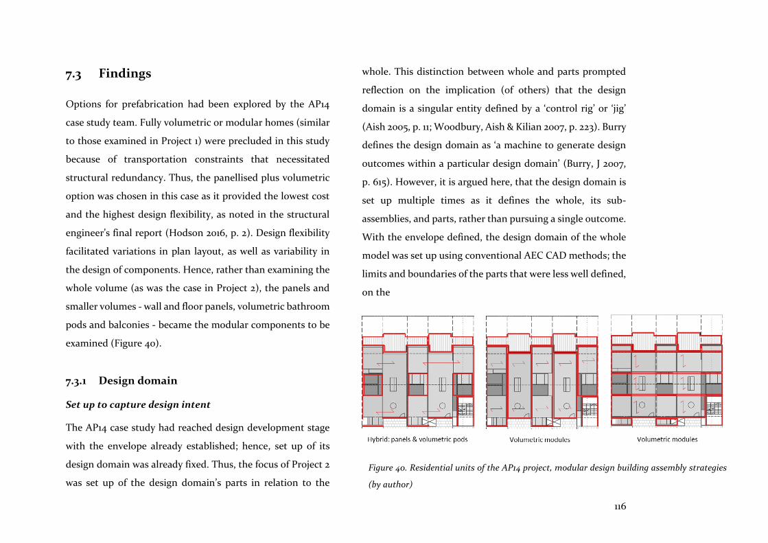
116
7.3 Findings
Options for prefabrication had been explored by the AP14
case study team. Fully volumetric or modular homes (similar
to those examined in Project 1) were precluded in this study
because of transportation constraints that necessitated
structural redundancy. Thus, the panellised plus volumetric
option was chosen in this case as it provided the lowest cost
and the highest design flexibility, as noted in the structural
engineer’s final report (Hodson 2016, p. 2). Design flexibility
facilitated variations in plan layout, as well as variability in
the design of components. Hence, rather than examining the
whole volume (as was the case in Project 2), the panels and
smaller volumes - wall and floor panels, volumetric bathroom
pods and balconies - became the modular components to be
examined (Figure 40).
7.3.1 Design domain
Set up to capture design intent
The AP14 case study had reached design development stage
with the envelope already established; hence, set up of its
design domain was already fixed. Thus, the focus of Project 2
was set up of the design domain’s parts in relation to the
whole. This distinction between whole and parts prompted
reflection on the implication (of others) that the design
domain is a singular entity defined by a ‘control rig’ or ‘jig’
(Aish 2005, p. 11; Woodbury, Aish & Kilian 2007, p. 223). Burry
defines the design domain as ‘a machine to generate design
outcomes within a particular design domain’ (Burry, J 2007,
p. 615). However, it is argued here, that the design domain is
set up multiple times as it defines the whole, its sub-
assemblies, and parts, rather than pursuing a single outcome.
With the envelope defined, the design domain of the whole
model was set up using conventional AEC CAD methods; the
limits and boundaries of the parts that were less well defined,
on the
Figure 40. Residential units of the AP14 project, modular design building assembly strategies
(by author)
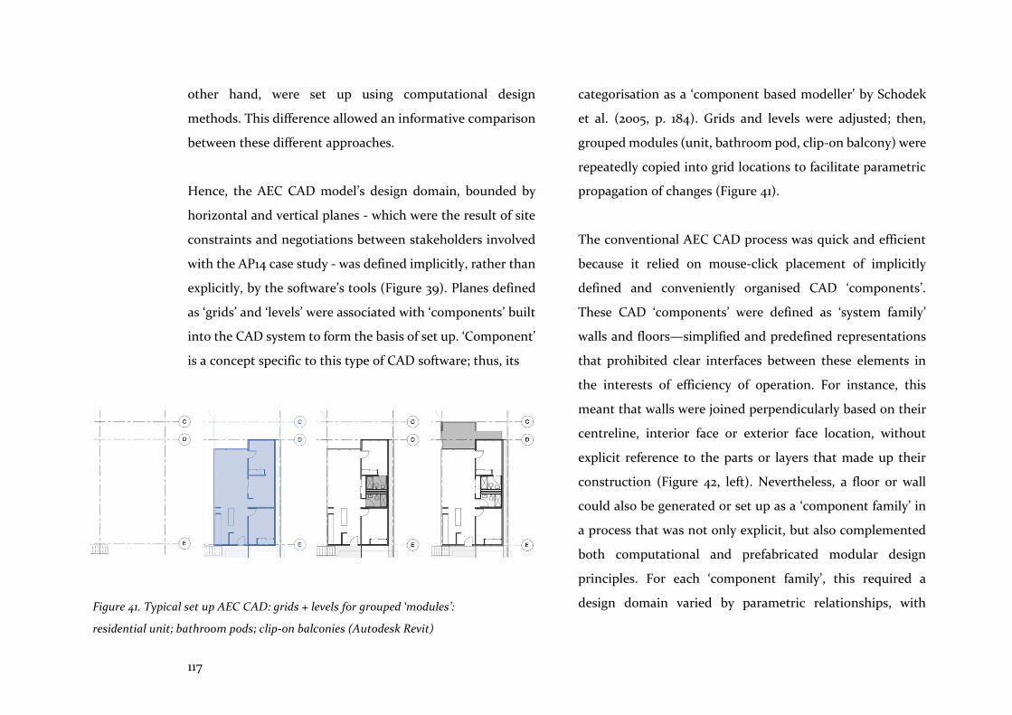
117
other hand, were set up using computational design
methods. This difference allowed an informative comparison
between these different approaches.
Hence, the AEC CAD model’s design domain, bounded by
horizontal and vertical planes - which were the result of site
constraints and negotiations between stakeholders involved
with the AP14 case study - was defined implicitly, rather than
explicitly, by the software’s tools (Figure 39). Planes defined
as ‘grids’ and ‘levels’ were associated with ‘components’ built
into the CAD system to form the basis of set up. ‘Component’
is a concept specific to this type of CAD software; thus, its
categorisation as a ‘component based modeller’ by Schodek
et al. (2005, p. 184). Grids and levels were adjusted; then,
grouped modules (unit, bathroom pod, clip-on balcony) were
repeatedly copied into grid locations to facilitate parametric
propagation of changes (Figure 41).
The conventional AEC CAD process was quick and efficient
because it relied on mouse-click placement of implicitly
defined and conveniently organised CAD ‘components’.
These CAD ‘components’ were defined as ‘system family’
walls and floors—simplified and predefined representations
that prohibited clear interfaces between these elements in
the interests of efficiency of operation. For instance, this
meant that walls were joined perpendicularly based on their
centreline, interior face or exterior face location, without
explicit reference to the parts or layers that made up their
construction (Figure 42, left). Nevertheless, a floor or wall
could also be generated or set up as a ‘component family’ in
a process that was not only explicit, but also complemented
both computational and prefabricated modular design
principles. For each ‘component family’, this required a
design domain varied by parametric relationships, with Figure 41. Typical set up AEC CAD: grids + levels for grouped ‘modules’:
residential unit; bathroom pods; clip-on balconies (Autodesk Revit)

118
careful consideration of material dimensions and structural
properties (Figure 42, right).
Set up of floor panels
To explore more fully the compatibility between this CAD
method and prefabricated modular design principles, a
‘component family’ CLT floor panel was set up with its own
design domain (Figure 43). Rather than geometry, the
outcome was a topological description of relationships
defined by explicit parametric values that could be adjusted
at future stages of the design process; at this stage, however,
length and width parameter values were allowed to vary. The
material’s dimensional and structural properties, and
transportation logistics, would eventually determine these
values. From this point forward, in this chapter, the term
‘component’ will be used interchangeably with ‘panel’, and
will refer more specifically to a physical entity with material
properties, rather than to a virtual entity defined by CAD
software.
Because the intention was to create different panel types and
locate these in the model framework, the act of placement
Figure 42. Set up of residential unit module: ‘system family’ predefined components (left);
‘component family’ explicitly defined components (right) (Autodesk Revit)

119
needed careful consideration. In particular, the component’s
origin determined precise spatial placement in the model’s
framework and its interface relationship to other instantiated
floor components. It also influenced the facility with which
automated placement procedures might be used later on.
Furthermore, the interfaces, or edges, had to be considered
for all likely variations, including overlapped notches and
butt joints that might meet on the outside, centre, or inside
line in relation to wall components. The positioning and
addition of fixings was also determined automatically,
making use of formulas associated with the panel’s width
dimension.
Figure 43. Floor panel design domain: a template for floor panel types in Project 2 (Autodesk Revit)
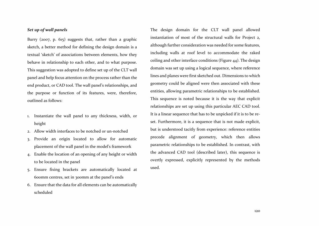
120
Set up of wall panels
Burry (2007, p. 615) suggests that, rather than a graphic
sketch, a better method for defining the design domain is a
textual ‘sketch’ of associations between elements, how they
behave in relationship to each other, and to what purpose.
This suggestion was adopted to define set up of the CLT wall
panel and help focus attention on the process rather than the
end product, or CAD tool. The wall panel’s relationships, and
the purpose or function of its features, were, therefore,
outlined as follows:
1. Instantiate the wall panel to any thickness, width, or
height
2. Allow width interfaces to be notched or un-notched
3. Provide an origin located to allow for automatic
placement of the wall panel in the model’s framework
4. Enable the location of an opening of any height or width
to be located in the panel
5. Ensure fixing brackets are automatically located at
600mm centres, set in 300mm at the panel’s ends
6. Ensure that the data for all elements can be automatically
scheduled
The design domain for the CLT wall panel allowed
instantiation of most of the structural walls for Project 2,
although further consideration was needed for some features,
including walls at roof level to accommodate the raked
ceiling and other interface conditions (Figure 44). The design
domain was set up using a logical sequence, where reference
lines and planes were first sketched out. Dimensions to which
geometry could be aligned were then associated with these
entities, allowing parametric relationships to be established.
This sequence is noted because it is the way that explicit
relationships are set up using this particular AEC CAD tool.
It is a linear sequence that has to be unpicked if it is to be re-
set. Furthermore, it is a sequence that is not made explicit,
but is understood tacitly from experience: reference entities
precede alignment of geometry, which then allows
parametric relationships to be established. In contrast, with
the advanced CAD tool (described later), this sequence is
overtly expressed, explicitly represented by the methods
used.
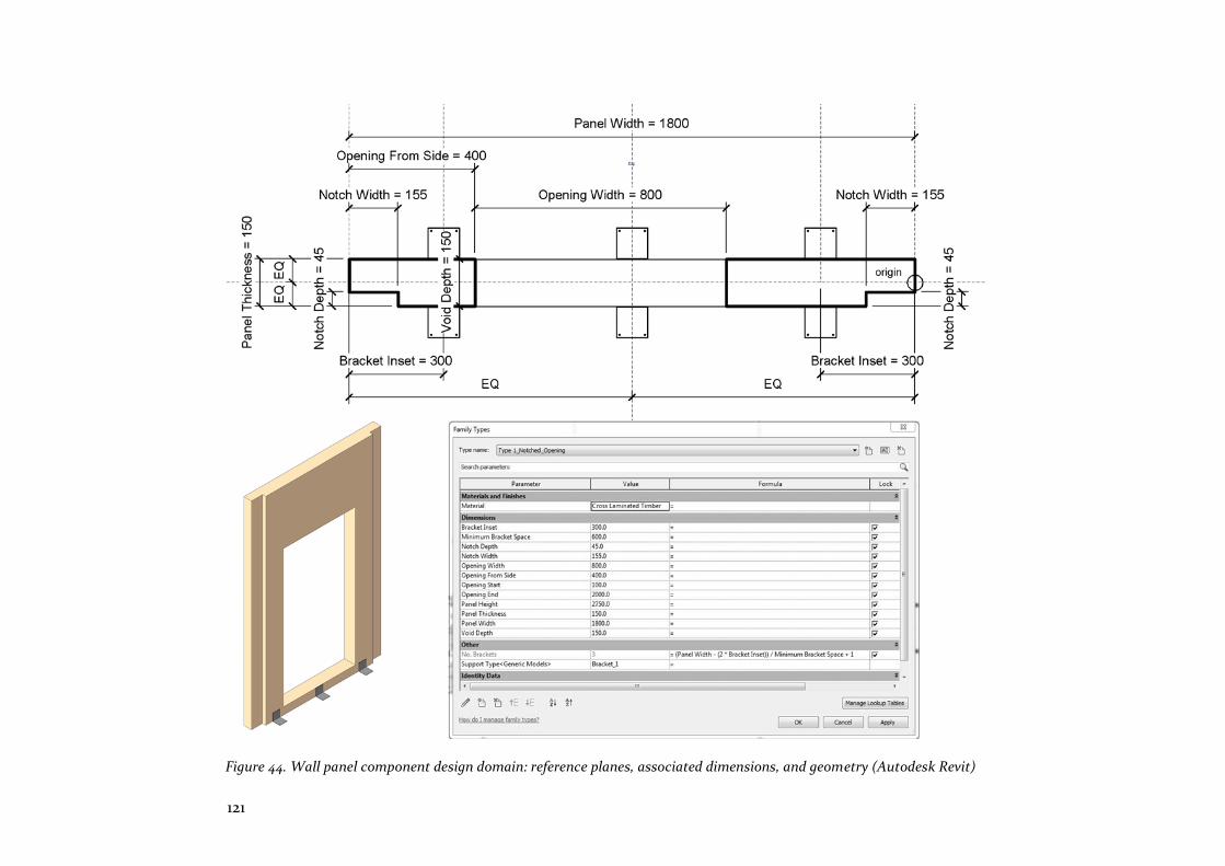
121
Figure 44. Wall panel component design domain: reference planes, associated dimensions, and geometry (Autodesk Revit)
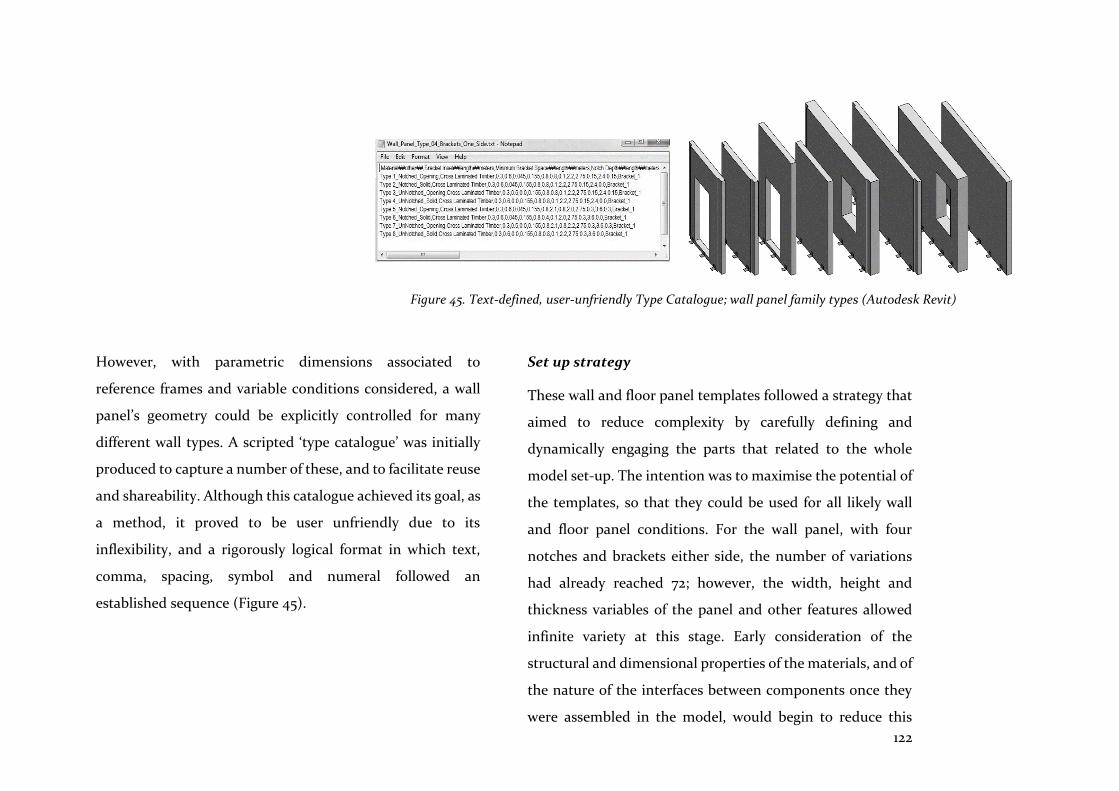
122
However, with parametric dimensions associated to
reference frames and variable conditions considered, a wall
panel’s geometry could be explicitly controlled for many
different wall types. A scripted ‘type catalogue’ was initially
produced to capture a number of these, and to facilitate reuse
and shareability. Although this catalogue achieved its goal, as
a method, it proved to be user unfriendly due to its
inflexibility, and a rigorously logical format in which text,
comma, spacing, symbol and numeral followed an
established sequence (Figure 45).
Set up strategy
These wall and floor panel templates followed a strategy that
aimed to reduce complexity by carefully defining and
dynamically engaging the parts that related to the whole
model set-up. The intention was to maximise the potential of
the templates, so that they could be used for all likely wall
and floor panel conditions. For the wall panel, with four
notches and brackets either side, the number of variations
had already reached 72; however, the width, height and
thickness variables of the panel and other features allowed
infinite variety at this stage. Early consideration of the
structural and dimensional properties of the materials, and of
the nature of the interfaces between components once they
were assembled in the model, would begin to reduce this
Figure 45. Text-defined, user-unfriendly Type Catalogue; wall panel family types (Autodesk Revit)
123
number of variations. However, the all-encompassing nature
of these templates involved a trade-off between complexity
and flexibility, with both qualities being captured by the
functional and material properties of the fixed and variable
parametric values. This is addressed in more detail below.
Explicit set up of the templates, following a logical sequence,
was a rigorous exercise. However, visualisation of the
relationship between topological set-up, geometry, and
parametric values was facilitated by frequent flexing and
examination of these associations, in real-time, in a single
screen view. These abstract associations have been described
by Aish (2005, p. 11), using the programming concept of
‘indirection’. This concept is the ability to reference
something by using a name rather than the value itself; for
example, ‘Panel Width’ or ‘Bracket Inset’ (Figure 44). The
result of indirection is the creation of abstract distance
between the architect and design intent. Because set up of the
floor and wall templates involved relatively low levels of
complexity, the degree of distance or indirection between the
designer and design intent was limited. However, the
following exercise examines interoperability and the ease and
effectiveness with which these templated components can be
related to the whole model, inevitably increasing the overall
complexity of associations and inter-relationships.
7.3.2 Associative programming
Interface
AEC CAD has only recently adopted associative
programming as an add-on application to facilitate architects’
engagement with computational design methods by
manipulation of relationships between nodes and wires in the
graph environment. Hence, a visual programming graph
(Autodesk Dynamo), which represents associative
programming, was used to set up the model’s grids and levels,
and to facilitate placement of the wall and floor panel
components described in the previous chapter. Mouse-click
placement of components in model space was replaced by the
set up of a graph in which nodes described and generated the
location of levels, grids and intersection points, to which wall
and floor panels were to be associated.
As noted above, parametric set up of the wall and floor panel
templates had only resulted in limited indirection between
the framework, parametric values and geometry, as only a few
parameters were needed to generate geometric instances.

124
However, the visual programming graph interface separates
the graph’s representation of design intent (as wires and
nodes) from the geometric model to maintain intelligibility.
With this arrangement, indirection - the distance between
designer and design intent - is increased, as it becomes both
an abstract and a visual phenomenon (Figure 46).
Grid and level set up
The visual programming graph was used to examine
improvements to workflow and interoperability, rather than
the set up of geometrical entities. Therefore, instead of
utilising the implicitly defined grids and levels used to set up
the whole model (Figure 39), these grids and levels were
defined explicitly and parametrically, using nodes in the
visual programming graph.
The different conventions for set up of a grid using AEC CAD
compared to computational design methods are noted here
because they represent differences in spatial thinking and
awareness. Coordinates defined by the AEC CAD grid are
typically laid out numerically from 1 on the X-axis, and
alphabetically from A on the Y-axis, or vice versa. Coordinates
on the computational design grid, on the other hand, always
begin at the origin from 0, and progress numerically on the
Figure 46. Interface: model view (left); extent of the visual programming graph’s script (right) (Autodesk Revit & Dynamo)

125
X- and Y-axes. Consequently, mental computations were
required to translate a component from AEC grid location
[F,10], based on origin [A,1], to digital coordinate location
[5,9], based on origin [0,0]. While this might seem
insignificant, this tacit understanding is part of the terrain to
be mapped when moving between analogue and
computational design processes. It was also mainly for this
reason that, compared with mouse-click placement, more
work was needed to set up the model from the graph.
However, the benefits of explicit definition of coordinate
locations included (Figure 47):
• A record of the decisions and, therefore, the ability to
revise placement positions
• A greater level of precision in the placement of
components and, therefore, the ability to assess and plan
downstream prefabrication and assembly outcomes with
more confidence
• An ability to search for grid intersections and to extract
coordinates for placement of each panel
Figure 47. Set up of the model’s design domain to find grid intersection coordinates (Autodesk Dynamo)
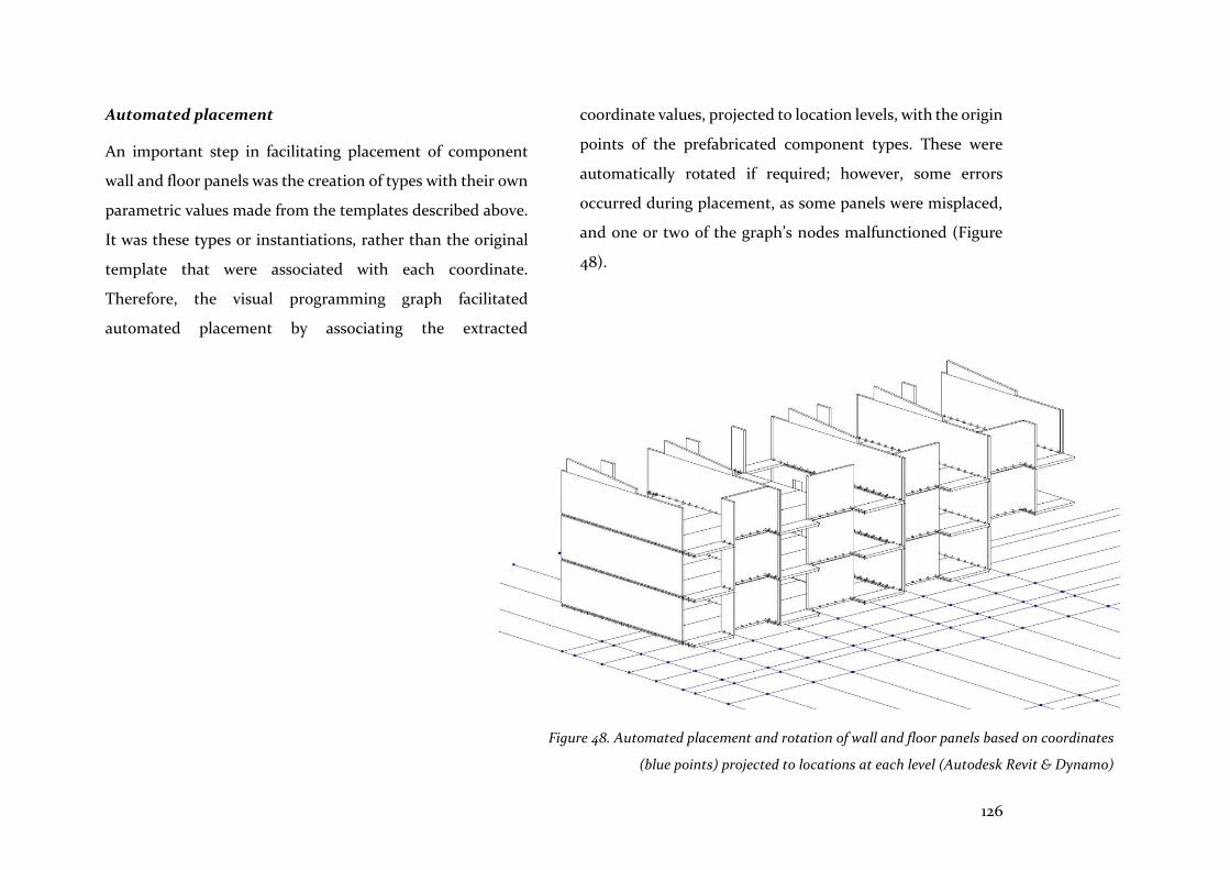
126
Automated placement
An important step in facilitating placement of component
wall and floor panels was the creation of types with their own
parametric values made from the templates described above.
It was these types or instantiations, rather than the original
template that were associated with each coordinate.
Therefore, the visual programming graph facilitated
automated placement by associating the extracted
coordinate values, projected to location levels, with the origin
points of the prefabricated component types. These were
automatically rotated if required; however, some errors
occurred during placement, as some panels were misplaced,
and one or two of the graph’s nodes malfunctioned (Figure
48).
Figure 48. Automated placement and rotation of wall and floor panels based on coordinates
(blue points) projected to locations at each level (Autodesk Revit & Dynamo)
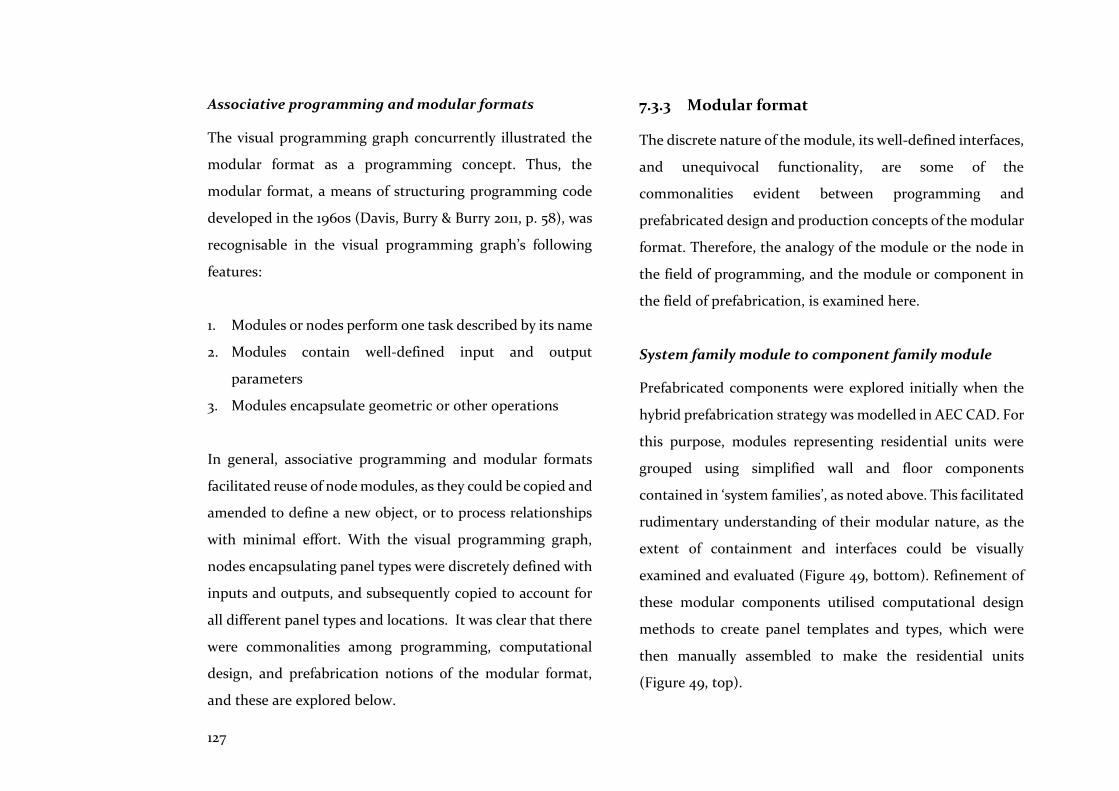
127
Associative programming and modular formats
The visual programming graph concurrently illustrated the
modular format as a programming concept. Thus, the
modular format, a means of structuring programming code
developed in the 1960s (Davis, Burry & Burry 2011, p. 58), was
recognisable in the visual programming graph’s following
features:
1. Modules or nodes perform one task described by its name
2. Modules contain well-defined input and output
parameters
3. Modules encapsulate geometric or other operations
In general, associative programming and modular formats
facilitated reuse of node modules, as they could be copied and
amended to define a new object, or to process relationships
with minimal effort. With the visual programming graph,
nodes encapsulating panel types were discretely defined with
inputs and outputs, and subsequently copied to account for
all different panel types and locations. It was clear that there
were commonalities among programming, computational
design, and prefabrication notions of the modular format,
and these are explored below.
7.3.3 Modular format
The discrete nature of the module, its well-defined interfaces,
and unequivocal functionality, are some of the
commonalities evident between programming and
prefabricated design and production concepts of the modular
format. Therefore, the analogy of the module or the node in
the field of programming, and the module or component in
the field of prefabrication, is examined here.
System family module to component family module
Prefabricated components were explored initially when the
hybrid prefabrication strategy was modelled in AEC CAD. For
this purpose, modules representing residential units were
grouped using simplified wall and floor components
contained in ‘system families’, as noted above. This facilitated
rudimentary understanding of their modular nature, as the
extent of containment and interfaces could be visually
examined and evaluated (Figure 49, bottom). Refinement of
these modular components utilised computational design
methods to create panel templates and types, which were
then manually assembled to make the residential units
(Figure 49, top).
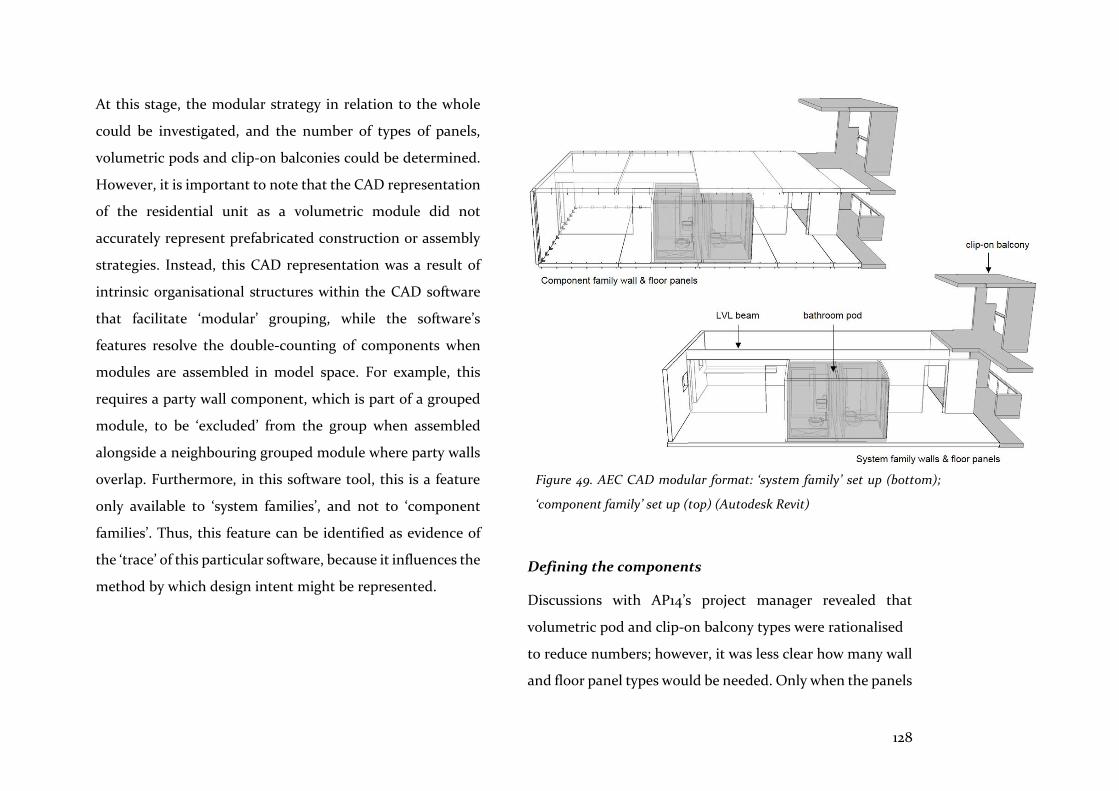
128
At this stage, the modular strategy in relation to the whole
could be investigated, and the number of types of panels,
volumetric pods and clip-on balconies could be determined.
However, it is important to note that the CAD representation
of the residential unit as a volumetric module did not
accurately represent prefabricated construction or assembly
strategies. Instead, this CAD representation was a result of
intrinsic organisational structures within the CAD software
that facilitate ‘modular’ grouping, while the software’s
features resolve the double-counting of components when
modules are assembled in model space. For example, this
requires a party wall component, which is part of a grouped
module, to be ‘excluded’ from the group when assembled
alongside a neighbouring grouped module where party walls
overlap. Furthermore, in this software tool, this is a feature
only available to ‘system families’, and not to ‘component
families’. Thus, this feature can be identified as evidence of
the ‘trace’ of this particular software, because it influences the
method by which design intent might be represented.
Defining the components
Discussions with AP14’s project manager revealed that
volumetric pod and clip-on balcony types were rationalised
to reduce numbers; however, it was less clear how many wall
and floor panel types would be needed. Only when the panels
Figure 49. AEC CAD modular format: ‘system family’ set up (bottom);
‘component family’ set up (top) (Autodesk Revit)

129
had been assembled by the visual programming method
described, could their interface conditions be interrogated so
that the number of types could be refined (Figure 50).
Subsequently it was determined that four wall panel and
three floor panel types would be needed to account for most
conditions. Following assembly by the visual programming
graph, parametric manipulation of panel types took place in
the CAD model.
Templates and types
Template set up facilitated the later stage process of fine-
tuning the parameters of each panel type to suit the particular
location or interface condition. For instance, wall brackets
could be flipped from one side to the other, include both
sides, or the end interface of wall panels could be changed
from notched to un-notched. Also, wall panel bracket or floor
panel screw spacings could be adjusted in relation to the
panel’s length. At Level 3, wall panels with roof extension
Figure 50. Half of the AP14 building: automated wall and floor panel assembly, 1st to 3rd floor levels (Autodesk Revit & Dynamo)
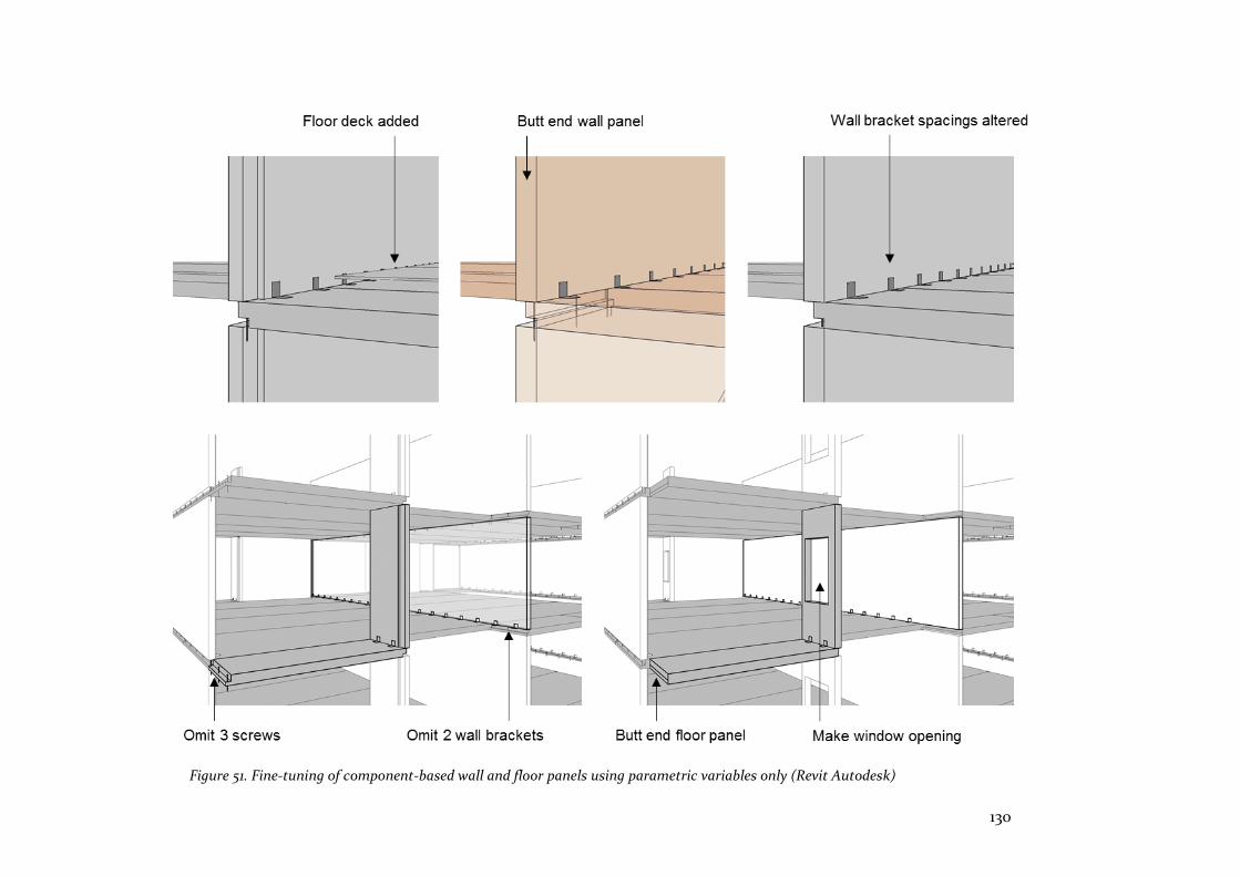
130
Figure 51. Fine-tuning of component-based wall and floor panels using parametric variables only (Revit Autodesk)
131
pieces were parametrically manipulated to be ‘on’ and visible,
whereas, in lower level locations, they were ‘off’ and invisible.
Similarly, acoustic built-up layers to floor panels could be
switched ‘on’ or ‘off’ depending on location, while interfaces
with other floor panels could switch between butt joints or
overlaps.
However, it soon became clear that more panel types would
be needed to deal with different interfaces, and to eventually
generate error-free fabrication documentation. For example,
some wall panels needed rebates inset from the ends, or
bracket fixings omitted where they extended beyond a floor
panel; alternatively, tolerance between wall and floor panel
junctions needed to be considered, to ensure seals could be
fixed in place (Figure 51).
In summary, automatic placement had facilitated visual
enquiry, and reinforced the idea that modular, formatted,
prefabricated components could be efficiently assembled in
the modelling environment to provide most of the variations
required. However, it was also clear that well-defined
interfaces were fundamental in providing flexibility.
Modular design programming concepts
A cautious approach was taken when searching for lessons
from the programming concept of the modular format that
were relevant to prefabrication. As noted earlier,
programming modules aim to be discrete and reusable
chunks, with well-defined interfaces, facilitating ease-of-use
and modifiability. These programming modules, their goals,
and features are described in more detail by Hasselbring
(2002, p. 2), and include:
Managerial goals:
1. Cost reduction.
2. Ease of assembly.
3. Reusability. The component’s potential for reuse.
4. Customisation and Flexibility.
5. Maintainability. The ease with which components can be
added or removed.
Technical features:
1. Coupling. The module provides a set of services through
its interfaces, and its main feature is ‘coupling’, the extent
to which the component is coupled with other
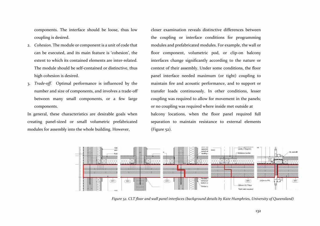
132
components. The interface should be loose, thus low
coupling is desired.
2. Cohesion. The module or component is a unit of code that
can be executed, and its main feature is ‘cohesion’, the
extent to which its contained elements are inter-related.
The module should be self-contained or distinctive, thus
high cohesion is desired.
3. Trade-off. Optimal performance is influenced by the
number and size of components, and involves a trade-off
between many small components, or a few large
components.
In general, these characteristics are desirable goals when
creating panel-sized or small volumetric prefabricated
modules for assembly into the whole building. However,
closer examination reveals distinctive differences between
the coupling or interface conditions for programming
modules and prefabricated modules. For example, the wall or
floor component, volumetric pod, or clip-on balcony
interfaces change significantly according to the nature or
context of their assembly. Under some conditions, the floor
panel interface needed maximum (or tight) coupling to
maintain fire and acoustic performance, and to support or
transfer loads continuously. In other conditions, lesser
coupling was required to allow for movement in the panels;
or no coupling was required where inside met outside at
balcony locations, when the floor panel required full
separation to maintain resistance to external elements
(Figure 52).
Figure 52. CLT floor and wall panel interfaces (background details by Kate Humphries, University of Queensland)
133
Therefore, the function of prefabricated modules was to meet
certain performance characteristics, while their interfaces
partially continued, continued, or separated these
performance characteristics. As the technical goal of the
programming module’s interface was to achieve low
coupling, any closer comparison of programming and
prefabricated module interfaces seemed unproductive.
However, in general, the programming concept of the
modular format contributed to better understanding when
creating prefabricated modules, as follows:
• Attention is focussed on the creation of self-contained,
distinct modules
• Goals are focussed on reusability, modifiability, trade-offs
and ease-of-use
• Management of modules with well-defined interfaces is
able to occur independently of other participants
Reusability, modifiability, trade-offs and ease-of-use
Reusability and modifiability partly depended on the panel’s
templates encompassing all possibilities, as defined by its
fixed and variable parameter values. Thus, if a wall panel type
could be defined, then it could be reused by instantiation in
the visual programming graph environment for placing in the
model. However, as noted with the programming concept of
modular design, it becomes apparent that trade-offs between
complexity and flexibility are required, as follows:
• Maximum flexibility. A template could be instantiated for
each wall or floor panel condition, where all the
parameter values would come into play, thus maximising
the flexibility of each type, but also maximising
complexity of the whole assembly.
• Average flexibility. A few types of panel utilising some of
the template’s parameters might reduce flexibility and
complexity.
• Minimum flexibility. Too many panel types utilising fewer
of the template’s parameters per instantiation would
minimise flexibility of each type and, again, maximise the
complexity of the whole assembly.
Hasselbring (2002, pp. 4-6) notes that, in software
programming, trade-offs between numbers of modules or
templates, and their reuse or instantiation as types to
regulate complexity, is supported by ‘domain engineering’,
which may be managed by a component library or a ‘pattern
134
language’. Therefore, in the building assembly context of
Project 2, just enough panel types needed to be made, with
enough parametric variables in each, to account for the
different conditions.
Ease-of-use and complexity were clearly related. Hence, in
the visual programming environment, to be able to precisely
place components based on their origin, all the coordinates
of intersecting grids were required. Mental computations,
visualisations of the ‘reference frame in space’, as proposed
by Schindler (1946, p. 44), were needed to translate graph
coordinates to AEC grid space, as noted earlier. Therefore,
the greater the number of types of panel created to deal with
each location or interface condition, the greater the
complexity and difficulty of utilising the visual programming
graph to translate and rotate modules in the CAD
environment. As also mentioned previously, errors had
started to creep into this process. Hence, the preference was
to allow for Maximum flexibility (as described above) by
reducing the number of panel types.
The difficulties with this task highlighted a problem with
visual programming graphs when ‘scaling-up’ to deal with the
complexity of geometric or component configuration: as
graph size and node quantities increase, intelligibility and
manageability decrease (Burnett & al 1995, p. 46). Thus, set
up of explicit, parametrically variable prefabricated
components, based on the modular design principles, and
automatically placed into the framework of the whole,
necessitated careful consideration of flexibility, complexity,
and the viability of the whole model.
Hierarchical structure and the modular format
To further examine these trade-offs between complexity and
flexibility, in the final experiment, an advanced CAD system
(Digital Project/CATIA) was utilised. Advanced CAD is
mainly used in the manufacturing sector for the design and
production of cars, aeroplanes, ships and other products. The
interface was significantly different to AEC CAD and the
visual programming graph, because parametric associations
were managed by explicit formation and representation of
hierarchical frameworks, and their corresponding
geometrical forms. While AEC CAD enabled creation of
parametrically associated components, it was noted that this
was an add-on feature with limited functionality, rather than
an integral feature of the software. By contrast, advanced

135
CAD’s explicit operations are fully parametric. However,
compared to AEC CAD, these fully integrated CAD systems
require greater cognitive effort and rigour to set up
components. Furthermore, as Schodek et al. (2005, p. 185)
note, these components have the intrinsic characteristics of
‘solid’ entities with physical properties, rather than the vague
and indistinct characteristics of AEC CAD entities.
Hierarchy and logic
The hierarchical tree, which graphically portrays the
relationship of parts to the whole, is the most prominent
representation of this mode of operation. In this software
environment, topological frames were set up and
parametrically associated with the geometry as ‘sketches’, to
create extrusions, pads, pockets and other geometric objects.
This meticulous process is known as ‘feature based’
modelling in the manufacturing sector (Schodek et al. 2005,
p. 202). Consequently, the wall panel component was made
up of three sketches—an opening, notches, and the ‘pad’ or
panel itself—that could then be examined in the hierarchical
tree, where their parameters were also clearly described and
modifiable (Figure 53).
Due to this hierarchical set-up, conceptualisation of
workflow, while rigorous, was unambiguous because it
followed a logical sequence. Accordingly, wall panel and
spaced bracket ‘parts’ were created separately, and assembled
as ‘products’. These were then assembled to make a more
complex product; that is, a unit of accommodation located in
relation to explicitly modelled grids and levels (Figure 54).
Hence, both the programming and prefabrication concepts of
the modular format could be clearly organised, explicitly
managed, and correspondingly represented by the interface
of the advanced CAD tool.
7.4 Summary
Integrated design tools and methods are needed if
production methods are to improve, and the one cannot
occur without the other. Furthermore, the synergies that
exist between better ways of designing and making need to
be better understood. Systems of designing and making are
inter-linked and already share concepts and goals that are
compatible. Modular design principles are one example
examined in this project (Project 2), where breaking down
complexity into understandable parts is at the root of such
thinking.
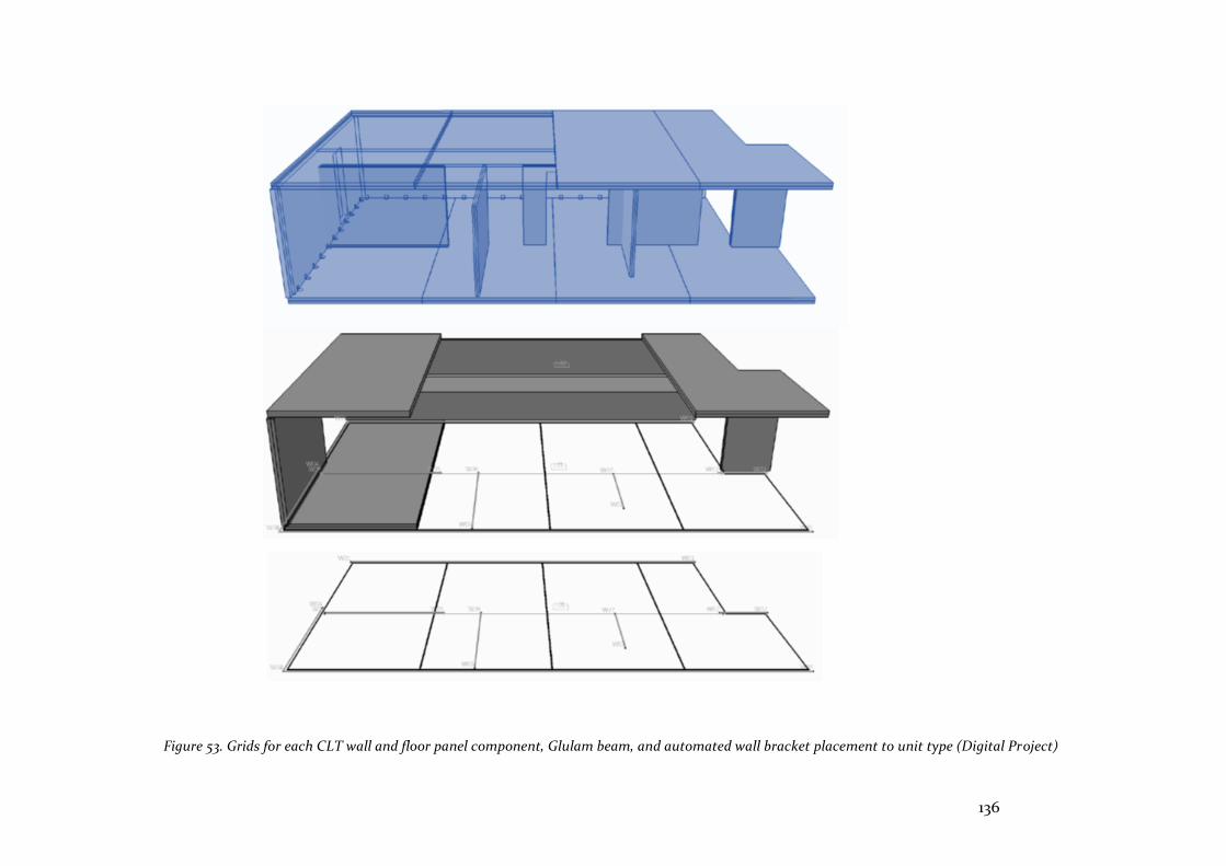
136
Figure 53. Grids for each CLT wall and floor panel component, Glulam beam, and automated wall bracket placement to unit type (Digital Project)
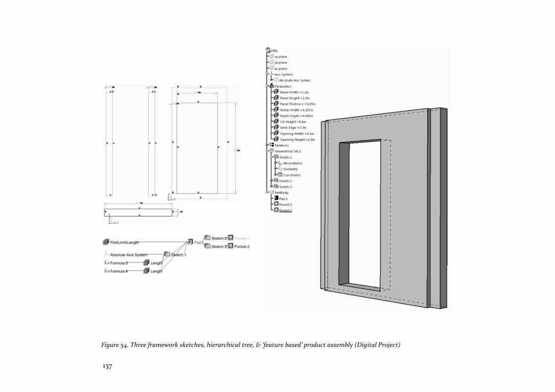
137
Figure 54. Three framework sketches, hierarchical tree, & ‘feature based’ product assembly (Digital Project)
138
The three experiments of Project 2 focussed on the
implementation of the computational design concepts of the
design domain, using associative programming and the
modular format. The design domain and its effectiveness
were examined as a device for setting up the framework of the
parametrically associated computational design model. The
contribution of the modular format was also investigated as
an expression of a computational design rule which,
according to Mitchell (1989, p. 8), contributes flexibility and
intelligibility. The subject for these investigations was a
three-storey, hybrid prefabricated residential project in
Brisbane (QLD, Australia).
It has been contended here that the design domain, rather
than being regarded as a singular entity, should be
understood as several entities that also define the sub-
assemblies and parts of the whole model. This understanding
facilitated set up of the prefabricated floor and wall panels,
and the volumetric bathroom pods. The parametric values
associated with these modular components attempted to
anticipate future conditions and interfaces that might be
encountered. It became clear that the use of too many fixed
and variable parameters in the set up of the panel templates
resulted in increased complexity, and decreased flexibility - a
trade-off that required careful consideration.
Associative programming is a recent addition to the
architect’s computational design tool-box and is expressed in
the form of visual programming graphs. The task examined
improvements to workflow through automatic placement of
components and revealed errors and inconsistencies when
panels were located in model space. Rather than contributing
to flexibility and intelligibility, associative programming
struggled to cope with scaling-up to the complexity of single
and associated design tasks. For this tool to be useful for
placement of prefabricated panels, or for simulation of
assembly processes, it would need to be more robust and
reliable.
The modular format as a programming concept is the
expression of a design rule that also aims to improve
flexibility and intelligibility in the use of computational
design tools. Prefabrication shares some of the characteristics
of this concept, including the creation of discrete and
reusable chunks, well-defined interfaces, ease-of-use, and
modifiability. It was clear that, in general, this analogy of

139
programming and prefabrication systems was useful,
although the nature of their interfaces did reveal fewer
commonalities. Finally, this experiment utilised advanced
CAD to set up a more rigorous hierarchical relationship
between components and panels. While the logical rigour of
this approach increased cognitive input, the concept of the
modular format appeared to be well-expressed, both
computationally and in the form of prefabricated
components and assemblies.
It is clear that concepts of the design domain do not fully
accord with architectural design frameworks. Furthermore,
the expression of design rules using associative programming
might improve ease of use and intelligibility for discrete
tasks, but it failed to address the whole task and its
interrelationships. The modular format, however, appears to
offer solutions which can foster integrated computational
design and prefabrication outcomes. These findings will be
examined in more detail in Chapter 9 (‘Discussion’), utilising
the MoI to assess the features and attributes of these methods
and tools. This examination is a precursor to rating the
degree of integration of each of the three projects in Chapter
10 (‘Integrated Modelling’).
140
This project appraises the nature and consequences of using
integrated computational design tools with compatible
prefabrication systems. It argues that early consideration of
coordination and modular design operate in harmony with
integrated parametric and automated design tools. It also
tests the assertion that, in the AEC sector, technological
change is needed, and that integrated design tools are
essential if design and production are to be joined in a
seamless process from conceptual design to realisation.
Prefabricated homes can only be improved with reliable,
user-friendly and robust design and production systems in
place.
8.1 Introduction
The interface of an advanced CAD system is examined,
including its cloud-based collaboration, its shared model
environment, and its parametric modelling and automated
techniques (based on scripting). These features are more
dispersed in the AEC CAD context where collaboration and
exchange of files occurs in silos, often resulting in data loss
and errors because of dissimilar software systems or versions,
and different protocols for exchange. AEC CAD also lacks a
shared model, while its parametric modelling and
automation capabilities are limited. By contrast, in the
manufacturing sector, CAD software has integrated these
features because its customers have demanded accuracy,
consistency, and reliability. This demand has encouraged
software vendors to engage with the full implications of
modelling complex solids and surfaces, in collaborative
environments that embrace all participants sharing a single
CAD model (Figure 55).
However, these advanced CAD systems are limited in their
design scope, because conceptual design tools are not yet
incorporated. Furthermore, these systems are closed,
denying open-source access to developers of add-ons and
plug-ins. They also rely on the inadequacies of neutral file
exchange protocols (IFCs) should interoperability with other
vendors’ platforms be required.
With these limitations in mind, and using an advanced CAD
tool common to the manufacturing sector, the design of
prefabricated homes that use modular design strategies is
evaluated. The main objective of this project is to examine
and refine a methodology that works symbiotically with the
8 A modular design
strategy
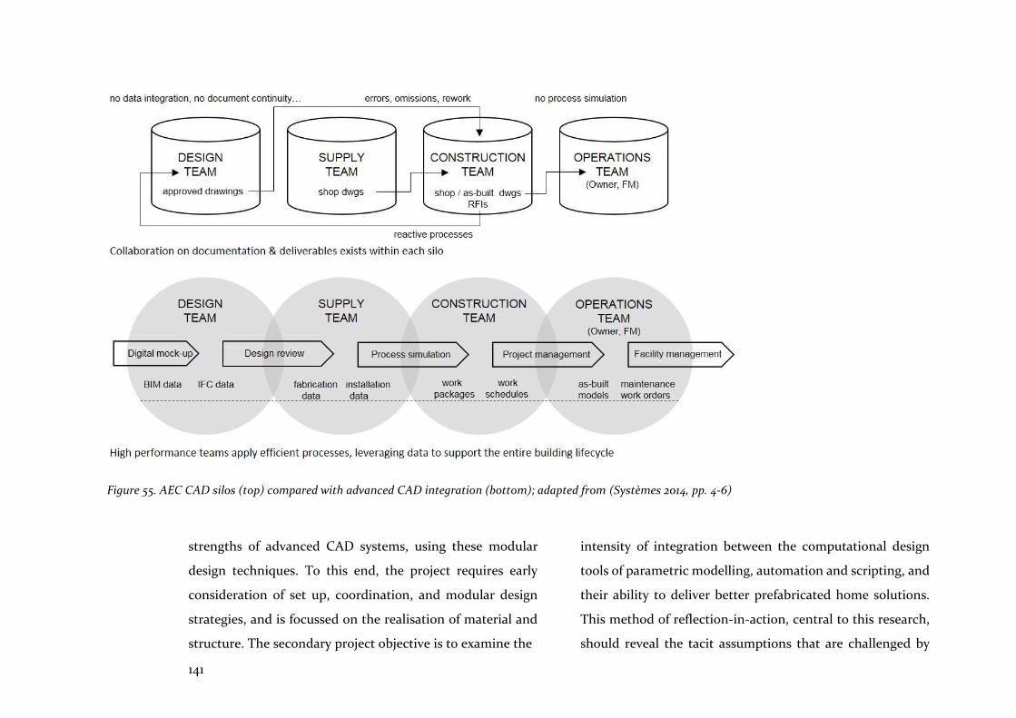
141
strengths of advanced CAD systems, using these modular
design techniques. To this end, the project requires early
consideration of set up, coordination, and modular design
strategies, and is focussed on the realisation of material and
structure. The secondary project objective is to examine the
intensity of integration between the computational design
tools of parametric modelling, automation and scripting, and
their ability to deliver better prefabricated home solutions.
This method of reflection-in-action, central to this research,
should reveal the tacit assumptions that are challenged by
Figure 55. AEC CAD silos (top) compared with advanced CAD integration (bottom); adapted from (Systèmes 2014, pp. 4-6)
142
these emergent tools and modes of practice. Indeed, as noted
by Loukissas (2009), it is important to acknowledge that the
wider impact that these tools can have on the culture of
architectural practice, requires further understanding.
8.2 Project methodology
Project 3 develops the general methodology described in
Chapter 1.3, and tests challenges to the hypothesis of this
research - that integrated computational design tools
combined with compatible prefabrication techniques will lead
to better housing alternatives – observing that the AEC sector
has failed to develop design and production tools that
implement objectives in an effective way, and that this failure
leads to cost inefficiencies, poor quality solutions, data loss in
the exchange of information, and a tendency for participants
to retreat into their own domains. The integration of design
and production tools offers solutions to these problems, and
can bring the AEC sector into the digital age with its
expectations of collaboration and seamless workflows. A
single tool is utilised to examine this proposition: Dassault 3D
Experience is an advanced CAD tool that is a closed
integrated system comprising many applications for the
implementation of different tasks (as discussed in Chapter 2).
As noted in the previous chapter, Project 3 was an adjunct to
the AP14 research case study funded by Queensland
Government Accelerate Partnerships. The project was carried
out (from October 2016 to March 2017, at the invitation of the
AP14 project manager) to examine integrated design and
production strategies that combine the advanced CAD
system with a hybrid prefabrication strategy.
The project was set up on a cloud-based server which is
centrally managed by Dassault, enabling project team
members to communicate remotely, with access to a single
shared model. A desktop-based virtual private network
(VPN) facilitated navigation, searching for data and files, the
loading and launching of applications, and collaboration
between participants. This tool was examined for its
hierarchically organised, parametric, solid-modelling
approach to creating modular components utilising ‘3D
Modelling’, ‘Social and Collaborative’, and ‘Information
Intelligence’ applications which are described in more detail
in Section 8.3.2. (Unless otherwise noted, the model images
referenced in the ‘Findings’ section later in this chapter were
collaboratively produced by the researcher and Graham Day,
University of Sydney).
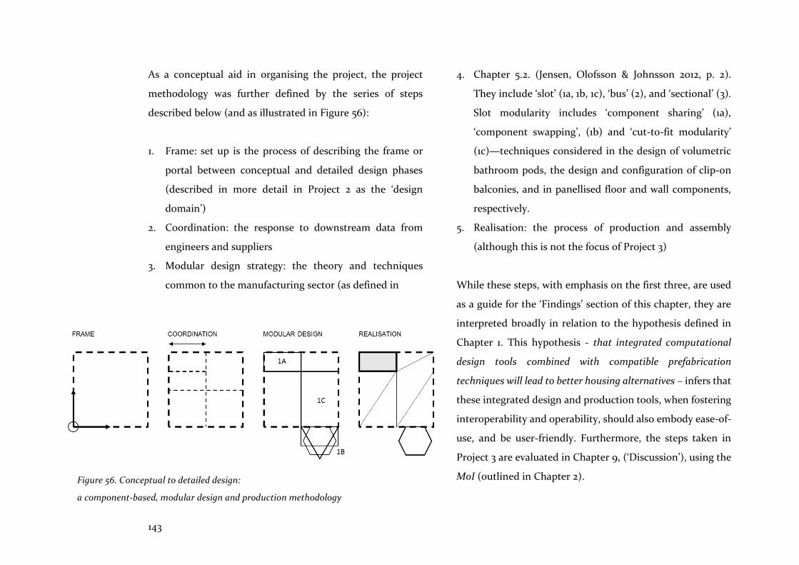
143
As a conceptual aid in organising the project, the project
methodology was further defined by the series of steps
described below (and as illustrated in Figure 56):
1. Frame: set up is the process of describing the frame or
portal between conceptual and detailed design phases
(described in more detail in Project 2 as the ‘design
domain’)
2. Coordination: the response to downstream data from
engineers and suppliers
3. Modular design strategy: the theory and techniques
common to the manufacturing sector (as defined in
4. Chapter 5.2. (Jensen, Olofsson & Johnsson 2012, p. 2).
They include ‘slot’ (1a, 1b, 1c), ‘bus’ (2), and ‘sectional’ (3).
Slot modularity includes ‘component sharing’ (1a),
‘component swapping’, (1b) and ‘cut-to-fit modularity’
(1c)—techniques considered in the design of volumetric
bathroom pods, the design and configuration of clip-on
balconies, and in panellised floor and wall components,
respectively.
5. Realisation: the process of production and assembly
(although this is not the focus of Project 3)
While these steps, with emphasis on the first three, are used
as a guide for the ‘Findings’ section of this chapter, they are
interpreted broadly in relation to the hypothesis defined in
Chapter 1. This hypothesis - that integrated computational
design tools combined with compatible prefabrication
techniques will lead to better housing alternatives – infers that
these integrated design and production tools, when fostering
interoperability and operability, should also embody ease-of-
use, and be user-friendly. Furthermore, the steps taken in
Project 3 are evaluated in Chapter 9, (‘Discussion’), using the
MoI (outlined in Chapter 2).
Figure 56. Conceptual to detailed design:
a component-based, modular design and production methodology

144
Although the research hypothesis states that a technological
approach to the integration of computational design tools is
needed, it is acknowledged that architecture in the digital age
is still a discipline in which project management and design
team members collaborate interactively, in an open-ended
process. As Carpo (2011, p. 127) observes, the goal today is to
produce variability, based on social responsibility in design
and resource use. Therefore, as noted in Chapter 1
(‘Introduction’), it is recognised that management changes—
including partnering agreements or Integrated Project
Delivery (IPD)—would occur concurrently with these
technological innovations. However, their study is beyond
the scope of this research.
8.3 Findings
Following the steps noted above, a strategy is examined to
create modules that are adaptable and understandable as
explicit, self-contained subsystems, and whose interactions
with other modules are clearly defined. Usually, advanced
CAD tools are the domain of manufacturing and product
engineers; here, however, they are examined from the
architect’s perspective, in the context of the AEC sector. To
date, the larger AEC CAD software companies and the AEC
sector have ignored these lessons from the manufacturing
sector. Therefore, this examination is instructive, and its
lessons are pertinent if the AEC sector is to integrate its tools
and methods, and improve its outcomes.
8.3.1 Frame
Set up of the framework
Project 3 began with the drafting of grids, placement of levels,
and location of axes in respect to context, and in anticipation
of the placement of panellised walls and floors, volumetric
bathroom pods and clip-on balconies. However, making this
spatial framework was a more intricate process than the
simple placement of reference points in space. This was
because these points also represented location and direction,
had relationships with other points and primitives, and
became an anchor to which other parts accreted. Location of
points, lines, and planes was, therefore, the foundation of the
design modelling methodology, and simultaneously
accounted for conception and realisation as the model
developed in complexity (Figure 57).

145
Figure 57. Setting up the frame of the building (top); a CLT wall panel template (bottom-left); a clip-on-balcony template (bottom-right); and an LGS stud part
(bottom), utilising points, lines, planes, levels and directional axes
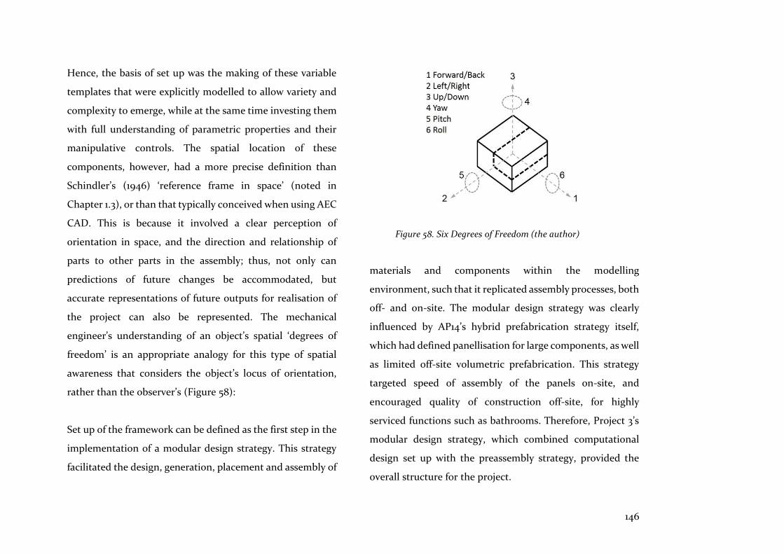
146
Hence, the basis of set up was the making of these variable
templates that were explicitly modelled to allow variety and
complexity to emerge, while at the same time investing them
with full understanding of parametric properties and their
manipulative controls. The spatial location of these
components, however, had a more precise definition than
Schindler’s (1946) ‘reference frame in space’ (noted in
Chapter 1.3), or than that typically conceived when using AEC
CAD. This is because it involved a clear perception of
orientation in space, and the direction and relationship of
parts to other parts in the assembly; thus, not only can
predictions of future changes be accommodated, but
accurate representations of future outputs for realisation of
the project can also be represented. The mechanical
engineer’s understanding of an object’s spatial ‘degrees of
freedom’ is an appropriate analogy for this type of spatial
awareness that considers the object’s locus of orientation,
rather than the observer’s (Figure 58):
Set up of the framework can be defined as the first step in the
implementation of a modular design strategy. This strategy
facilitated the design, generation, placement and assembly of
Figure 58. Six Degrees of Freedom (the author)
materials and components within the modelling
environment, such that it replicated assembly processes, both
off- and on-site. The modular design strategy was clearly
influenced by AP14’s hybrid prefabrication strategy itself,
which had defined panellisation for large components, as well
as limited off-site volumetric prefabrication. This strategy
targeted speed of assembly of the panels on-site, and
encouraged quality of construction off-site, for highly
serviced functions such as bathrooms. Therefore, Project 3’s
modular design strategy, which combined computational
design set up with the preassembly strategy, provided the
overall structure for the project.
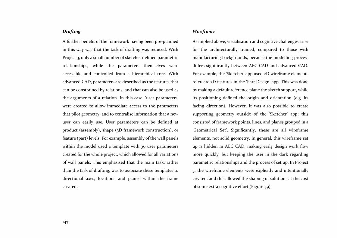
147
Drafting
A further benefit of the framework having been pre-planned
in this way was that the task of drafting was reduced. With
Project 3, only a small number of sketches defined parametric
relationships, while the parameters themselves were
accessible and controlled from a hierarchical tree. With
advanced CAD, parameters are described as the features that
can be constrained by relations, and that can also be used as
the arguments of a relation. In this case, ‘user parameters’
were created to allow immediate access to the parameters
that pilot geometry, and to centralise information that a new
user can easily use. User parameters can be defined at
product (assembly), shape (3D framework construction), or
feature (part) levels. For example, assembly of the wall panels
within the model used a template with 36 user parameters
created for the whole project, which allowed for all variations
of wall panels. This emphasised that the main task, rather
than the task of drafting, was to associate these templates to
directional axes, locations and planes within the frame
created.
Wireframe
As implied above, visualisation and cognitive challenges arise
for the architecturally trained, compared to those with
manufacturing backgrounds, because the modelling process
differs significantly between AEC CAD and advanced CAD.
For example, the ‘Sketcher’ app used 2D wireframe elements
to create 3D features in the ‘Part Design’ app. This was done
by making a default reference plane the sketch support, while
its positioning defined the origin and orientation (e.g. its
facing direction). However, it was also possible to create
supporting geometry outside of the ‘Sketcher’ app; this
consisted of framework points, lines, and planes grouped in a
‘Geometrical Set’. Significantly, these are all wireframe
elements, not solid geometry. In general, this wireframe set
up is hidden in AEC CAD, making early design work flow
more quickly, but keeping the user in the dark regarding
parametric relationships and the process of set up. In Project
3, the wireframe elements were explicitly and intentionally
created, and this allowed the shaping of solutions at the cost
of some extra cognitive effort (Figure 59).

148
Figure 59. ‘Sketcher’ defines wireframe set up (top); Wall panel template parameters x 36 and ‘Rule’ directions (bottom)
(Graham Day, University of Sydney)
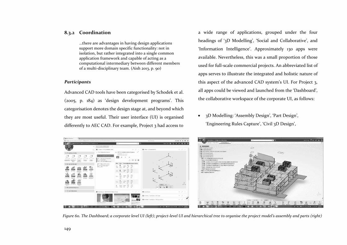
149
8.3.2 Coordination
…there are advantages in having design applications support more domain specific functionality: not in isolation, but rather integrated into a single common application framework and capable of acting as a computational intermediary between different members of a multi-disciplinary team. (Aish 2013, p. 90)
Participants
Advanced CAD tools have been categorised by Schodek et al.
(2005, p. 184) as ‘design development programs’. This
categorisation denotes the design stage at, and beyond which
they are most useful. Their user interface (UI) is organised
differently to AEC CAD. For example, Project 3 had access to
a wide range of applications, grouped under the four
headings of ‘3D Modelling’, ‘Social and Collaborative’, and
‘Information Intelligence’. Approximately 130 apps were
available. Nevertheless, this was a small proportion of those
used for full-scale commercial projects. An abbreviated list of
apps serves to illustrate the integrated and holistic nature of
this aspect of the advanced CAD system’s UI. For Project 3,
all apps could be viewed and launched from the ‘Dashboard’,
the collaborative workspace of the corporate UI, as follows:
• 3D Modelling: ‘Assembly Design’, ‘Part Design’,
‘Engineering Rules Capture’, ‘Civil 3D Design’,
Figure 60. The Dashboard; a corporate level UI (left); project-level UI and hierarchical tree to organise the project model’s assembly and parts (right)
150
‘Engineering Templates’, ‘Component Family’ and ‘Live
Rendering’
• Social and Collaborative: ‘3D Space’ and ‘3D Play’
• Information Intelligence: ‘3D Dashboard’
At project level, a hierarchical UI defined a model shared by
all team members (Figure 60). Reflecting its manufacturing
background, the project was feature-based. This meant that
objects were modelled with solid geometry modified by
pockets, holes, fillets, flanges and slots, and were
dimensionally driven with a tree-like visual display—in text
and symbols—of their internal structure. Close collaboration
with other engineers was supported by simulation apps for
structural analysis and computational fluid dynamic analysis;
however, these were not used in Project 3. All files and
documents related to the project were contained in a
database and stored in the cloud from where they were
opened. Depending on hierarchical level (assembly or part),
apps were selected as required for the task. Therefore, during
the induction phase, it became clear that the project and
model’s UIs were comprehensive, and provided a clear visual
and conceptual understanding of the whole that was open to
all participants.
Parametric modelling
The researchers built up the parametric model’s framework
during a collaborative coordination exercise that required
anticipation of future automated placement of assemblies
and components. This exercise instilled understanding from
the outset, and encouraged early but precise and
parametrically variable prediction of the placement of wall
and floor panels, volumetric pods and clip-on balconies
(based on the modular design principles noted earlier).
Parametric relationships were manually defined—a lengthy
and rigorous process. However, the interoperability of
components and the whole that this allowed was
fundamental to the coordination of Project 3, both among
participants, and among and within the model’s objects.
Shared model
The AP14 shared model contained complex parametric and
scripted knowledge and required collaborative
understanding to set up robust, logical relationships between
assemblies and parts. Shareability of this knowledge and
understanding relied on the clarity of the hierarchical tree of
relationships, which enabled ease of access and re-use of each
other’s model files, when needed. Project 3’s shared model

151
proved to be parametrically robust and, with the careful pre-
planning of anticipated changes noted above, the assembly
and part models stood up to the constant flexing and changes
required.
Concurrent access to documents was managed by the
‘Collaboration and Approvals’ app, which defined the
lifecycle state of the document via its maturity level, and via
the ability to ‘check-in’ or ‘check-out’ the document. For
example, in the ‘Private’ state, the document was accessible
by the owner only; in the ‘In Work’ state, on the other hand,
the document could be modified, a new revision created, or
it could be demoted by the owner to the ‘Private’ state. If
‘Frozen’, the document would be under review; if ‘Released’,
it would be available for production and delivery. When no
longer in use, the document was promoted to the ‘Obsolete’
state. ‘Checkout’ enabled the document to be downloaded
from the cloud to the PC when the document was locked for
independent working. With ‘Upload/Check In’, a new version
of the document was automatically created. It was also
possible to ‘Reserve’ a document, thus activating a green key
icon that indicated owner access, or a red key icon that
indicated that non-owners’ were prevented access. In short,
to safeguard the documents, the system managed and kept
track of all states, and of checked-in and checked-out
versions (Systèmes 2017a).
Dimensions
Panellised CLT walls and floors, fully fabricated off-site, were
chosen because they were more adaptable to space planning
variations, and to later changes in design, in comparison with
volumetric, off-site, pre-assembled components. On the AP14
case study, before the researchers began to investigate using
advanced CAD, the properties of CLT panels had been
analysed in consultation with the structural engineers and
suppliers. Therefore, maximum length, width, thickness
dimensions and spanning direction of the CLT, as well as the
coordinating requirements for Glulam infill and support
beams, were all considered early during the schematic design
stage. Thus, the upstream flow of data had reached the
researchers in a timely manner; this, in turn, enabled set up
of the frame, coordination, and modular design steps to
progress, with researchers having the confidence that
outcomes could be met (Figure 61).

152
Figure 61. Coordination and modular design, with CLT wall / floor panels (cut-to-fit), and LGS pods (component sharing)
153
Checks and Rules
Coordination of complex modular relationships also
benefited from advanced CAD instruments that monitored
the status of component accuracy and location in relation to
other components. For example, ‘Check’ is a set of statements
intended to inform the user whether the specified conditions
are fulfilled or not. It does not modify the object to which it
is applied, but uses traffic light icons switched between red
and green (according to the check status) to assess whether a
parameter is responding to a technical limitation, or to a set
of conditions. For the CLT wall panels, a check was first
defined in non-programming language as follows: ‘Check that
the rebate depth parameter is less than or equal to the wall
thickness’.
Additionally, the ‘Rule’ feature facilitated variations to
modules, and was written in Enterprise Knowledge Language
(EKL) to control relationships between parameters. For
example, the CLT wall panel had notches, openings and
rebates that were activated or deactivated depending on the
panel’s location. This could be defined simply as follows: ‘If
the parameter for the balcony cut-out to the wall panel
indicates ‘ON’, then activate it; if ‘OFF’, then deactivate it’.
Therefore, rules and checks facilitated conditional control of
parametric variation. These monitoring instruments
contributed to refining the detail of the modular design
strategy.
Automation
Automation was implemented using ‘Knowledgeware’, as
defined by the ‘Engineering Rules Capture’ app that allowed
knowledge, or ‘intelligence’, to be embedded in the project.
This process reduced errors and maximised the productivity
of repetitive tasks. The app embedded knowledge as
formulas, rules, checks, and knowledge patterns within the
hierarchical tree. The EKL programming language enabled
definition of associative rules to drive parameter propagation,
and for the transformation and instantiation of objects.
Features that enabled instantiation included, ‘Engineering
Templates’ (assembly level), ‘PowerCopies’ (part level) and
user defined features (UDFs at part level). The latter two were
components and features that could be retrieved from the
database for re-use, to avoid recreating frequently used
geometries.

154
Figure 62. Visual perception of integration of modular design components: the building, the pod and its parts

155
Visualisation
Understanding of—and, therefore, the ability to visually
coordinate—the many parts and components created for
Project 3 was partly dependent on the ability to perceive
clearly self-contained, explicitly defined separate objects. The
process of making the components was reproduced by their
representation, so that relationships, types of components
and materials could be quickly and visually checked (Figure
62).
Interference Simulation
A more thorough understanding of coordination problems
was provided by the ‘Interference Simulation’ feature. A full
assembly of Project 3 was analysed for all clashes, some of
Figure 63. ‘Interference Simulation’: clash detection for all components and parts of the model
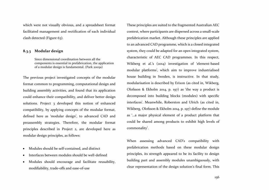
156
which were not visually obvious, and a spreadsheet format
facilitated management and rectification of each individual
clash detected (Figure 63).
8.3.3 Modular design
Since dimensional coordination between all the components is essential in prefabrication, the application of a modular design is fundamental. (Park 2005a)
The previous project investigated concepts of the modular
format common to programming, computational design and
building assembly activities, and found that its application
could enhance their compatibility, and deliver better design
solutions. Project 3 developed this notion of enhanced
compatibility, by applying concepts of the modular format,
defined here as ‘modular design’, to advanced CAD and
preassembly strategies. Therefore, the modular format
principles described in Project 2, are developed here as
modular design principles, as follows:
• Modules should be self-contained, and distinct
• Interfaces between modules should be well-defined
• Modules should encourage and facilitate reusability,
modifiability, trade-offs and ease-of-use
These principles are suited to the fragmented Australian AEC
context, where participants are dispersed across a small-scale
prefabrication market. Although these principles are applied
to an advanced CAD programme, which is a closed integrated
system, they could be adapted for an open integrated system,
characteristic of AEC CAD programmes. In this respect,
Wikberg et al.’s (2014) investigation of ‘element-based
modular platforms’, which aim to improve industrialised
house building in Sweden, is instructive. In that study,
modularisation is described by Erixon (as cited in, Wikberg,
Olofsson & Ekholm 2014, p. 197) as ‘the way a product is
decomposed into building blocks (modules) with specific
interfaces’. Meanwhile, Roberston and Ulrich (as cited in,
Wikberg, Olofsson & Ekholm 2014, p. 197) define the module
as ‘…a major physical element of a product platform that
could be shared among products to exhibit high levels of
commonality’.
When assessing advanced CAD’s compatibility with
prefabrication methods based on these modular design
principles, its strength appeared to be its facility to design
building part and assembly modules unambiguously, with
clear representation of the design solution’s final form. This
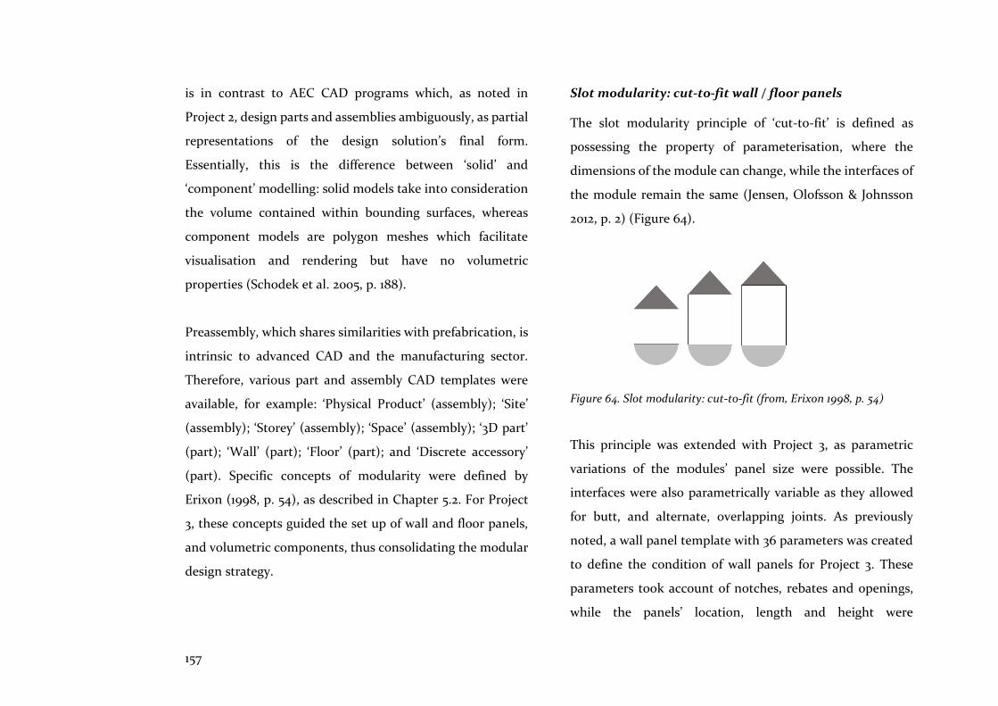
157
is in contrast to AEC CAD programs which, as noted in
Project 2, design parts and assemblies ambiguously, as partial
representations of the design solution’s final form.
Essentially, this is the difference between ‘solid’ and
‘component’ modelling: solid models take into consideration
the volume contained within bounding surfaces, whereas
component models are polygon meshes which facilitate
visualisation and rendering but have no volumetric
properties (Schodek et al. 2005, p. 188).
Preassembly, which shares similarities with prefabrication, is
intrinsic to advanced CAD and the manufacturing sector.
Therefore, various part and assembly CAD templates were
available, for example: ‘Physical Product’ (assembly); ‘Site’
(assembly); ‘Storey’ (assembly); ‘Space’ (assembly); ‘3D part’
(part); ‘Wall’ (part); ‘Floor’ (part); and ‘Discrete accessory’
(part). Specific concepts of modularity were defined by
Erixon (1998, p. 54), as described in Chapter 5.2. For Project
3, these concepts guided the set up of wall and floor panels,
and volumetric components, thus consolidating the modular
design strategy.
Slot modularity: cut-to-fit wall / floor panels
The slot modularity principle of ‘cut-to-fit’ is defined as
possessing the property of parameterisation, where the
dimensions of the module can change, while the interfaces of
the module remain the same (Jensen, Olofsson & Johnsson
2012, p. 2) (Figure 64).
Figure 64. Slot modularity: cut-to-fit (from, Erixon 1998, p. 54)
This principle was extended with Project 3, as parametric
variations of the modules’ panel size were possible. The
interfaces were also parametrically variable as they allowed
for butt, and alternate, overlapping joints. As previously
noted, a wall panel template with 36 parameters was created
to define the condition of wall panels for Project 3. These
parameters took account of notches, rebates and openings,
while the panels’ location, length and height were
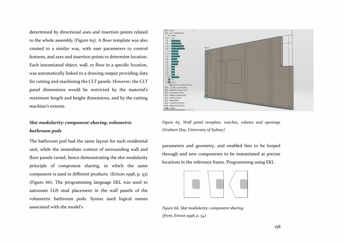
158
determined by directional axes and insertion points related
to the whole assembly (Figure 65). A floor template was also
created in a similar way, with user parameters to control
features, and axes and insertion points to determine location.
Each instantiated object, wall, or floor in a specific location,
was automatically linked to a drawing output providing data
for cutting and machining the CLT panels. However, the CLT
panel dimensions would be restricted by the material’s
maximum length and height dimensions, and by the cutting
machine’s extents.
Slot modularity: component-sharing, volumetric
bathroom pods
The bathroom pod had the same layout for each residential
unit, while the immediate context of surrounding wall and
floor panels varied, hence demonstrating the slot modularity
principle of component sharing, in which the same
component is used in different products (Erixon 1998, p. 53)
(Figure 66). The programming language EKL was used to
automate LGS stud placement in the wall panels of the
volumetric bathroom pods. Syntax used logical names
associated with the model’s
Figure 65. Wall panel template, notches, rebates and openings
(Graham Day, University of Sydney)
parameters and geometry, and enabled lists to be looped
through and new components to be instantiated at precise
locations in the reference frame. Programming using EKL
Figure 66. Slot modularity: component sharing
(from, Erixon 1998, p. 54).

159
captured the efficiency of automatic placement of members
at regular spacing, accounting for openings and different end
conditions. Again, it required careful set up of the framework
in recognition of orientation, direction, and placement
within the whole bathroom pod assembly. The EKL script
associated stud (part) to wall panel (part) to volumetric pod
(sub-assembly) to building framework (assembly), thus
demonstrating a rigorous and robust ability to parametrically
link part to part in a complex hierarchical whole (Figure 67).
Slot modularity: component swapping, clip-on-balconies
The most useful initial sketch for the associative geometry model is not a shape or a map but a description of what it should ‘do’… a machine to generate design outcomes within a particular design domain. (Burry, J 2007, p. 615)
Four different types of clip-on balconies were required for
Project 3, each meeting the main building’s floor panels and
external wall facades in similar ways. These varied
components meeting the same interface condition, defined
the slot modularity principle of component swapping, where
different components meet the same product (Erixon 1998, p.
53) (Figure 68). Variation was created and managed using
configuration applications common to the manufacturing
sector and advanced CAD.
Figure 68. Slot modularity: component sharing
(from, Erixon 1998, p. 54)
Figure 67. LGS stud placement and volumetric pod assembly: slot modularity and component sharing
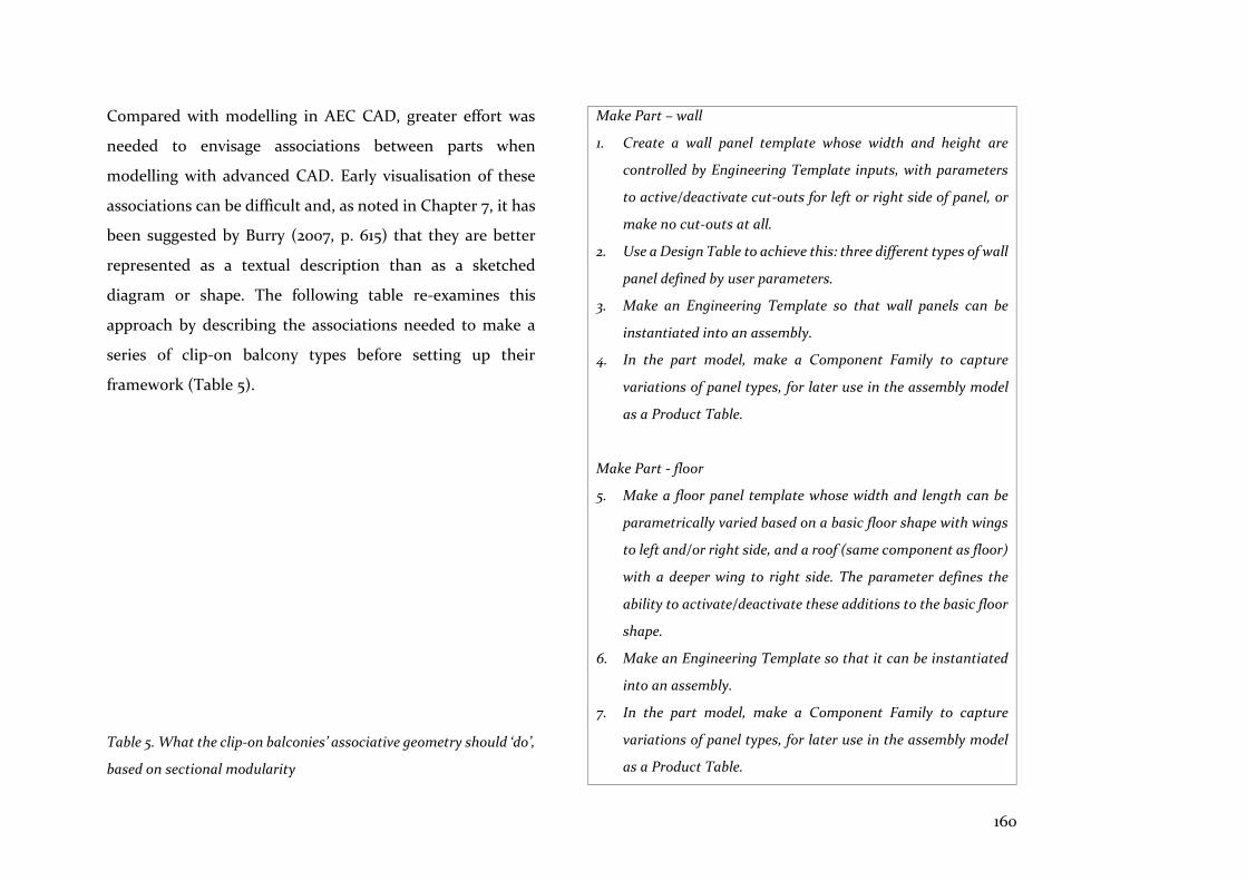
160
Compared with modelling in AEC CAD, greater effort was
needed to envisage associations between parts when
modelling with advanced CAD. Early visualisation of these
associations can be difficult and, as noted in Chapter 7, it has
been suggested by Burry (2007, p. 615) that they are better
represented as a textual description than as a sketched
diagram or shape. The following table re-examines this
approach by describing the associations needed to make a
series of clip-on balcony types before setting up their
framework (Table 5).
Table 5. What the clip-on balconies’ associative geometry should ‘do’,
based on sectional modularity
Make Part – wall
1. Create a wall panel template whose width and height are
controlled by Engineering Template inputs, with parameters
to active/deactivate cut-outs for left or right side of panel, or
make no cut-outs at all.
2. Use a Design Table to achieve this: three different types of wall
panel defined by user parameters.
3. Make an Engineering Template so that wall panels can be
instantiated into an assembly.
4. In the part model, make a Component Family to capture
variations of panel types, for later use in the assembly model
as a Product Table.
Make Part - floor
5. Make a floor panel template whose width and length can be
parametrically varied based on a basic floor shape with wings
to left and/or right side, and a roof (same component as floor)
with a deeper wing to right side. The parameter defines the
ability to activate/deactivate these additions to the basic floor
shape.
6. Make an Engineering Template so that it can be instantiated
into an assembly.
7. In the part model, make a Component Family to capture
variations of panel types, for later use in the assembly model
as a Product Table.
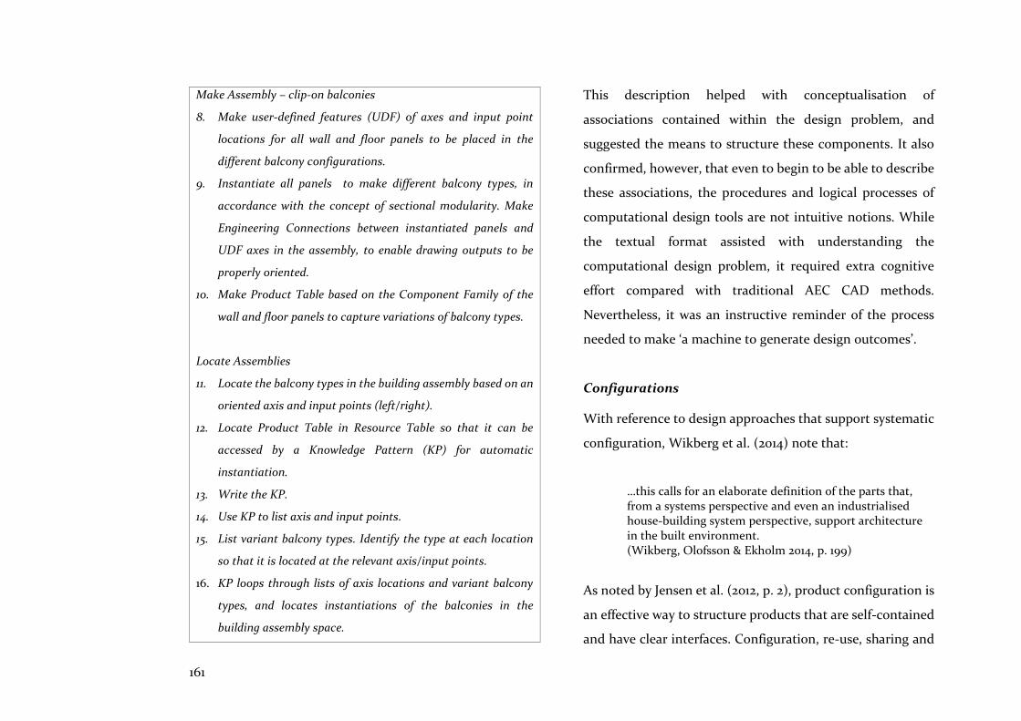
161
Make Assembly – clip-on balconies
8. Make user-defined features (UDF) of axes and input point
locations for all wall and floor panels to be placed in the
different balcony configurations.
9. Instantiate all panels to make different balcony types, in
accordance with the concept of sectional modularity. Make
Engineering Connections between instantiated panels and
UDF axes in the assembly, to enable drawing outputs to be
properly oriented.
10. Make Product Table based on the Component Family of the
wall and floor panels to capture variations of balcony types.
Locate Assemblies
11. Locate the balcony types in the building assembly based on an
oriented axis and input points (left/right).
12. Locate Product Table in Resource Table so that it can be
accessed by a Knowledge Pattern (KP) for automatic
instantiation.
13. Write the KP.
14. Use KP to list axis and input points.
15. List variant balcony types. Identify the type at each location
so that it is located at the relevant axis/input points.
16. KP loops through lists of axis locations and variant balcony
types, and locates instantiations of the balconies in the
building assembly space.
This description helped with conceptualisation of
associations contained within the design problem, and
suggested the means to structure these components. It also
confirmed, however, that even to begin to be able to describe
these associations, the procedures and logical processes of
computational design tools are not intuitive notions. While
the textual format assisted with understanding the
computational design problem, it required extra cognitive
effort compared with traditional AEC CAD methods.
Nevertheless, it was an instructive reminder of the process
needed to make ‘a machine to generate design outcomes’.
Configurations
With reference to design approaches that support systematic
configuration, Wikberg et al. (2014) note that:
…this calls for an elaborate definition of the parts that, from a systems perspective and even an industrialised house-building system perspective, support architecture in the built environment. (Wikberg, Olofsson & Ekholm 2014, p. 199)
As noted by Jensen et al. (2012, p. 2), product configuration is
an effective way to structure products that are self-contained
and have clear interfaces. Configuration, re-use, sharing and

162
variability of clip-on-balcony components were facilitated by
the use of spreadsheets. This familiar and easy-to-use
parametric method increased productivity by simplifying the
accessibility and visualisation of parametric associations
between parts and assemblies. Variations were initially
defined in a ‘Design Table’: a spreadsheet containing values
of the parameters of a model file, from which a ‘Component
Family’ was created to provide pre-defined sets of
configurations of the wall or floor component.
These components were parts or products that differed with
respect to their parameter values, and the ‘Component
Family’ app facilitated viewing and publishing to the data
base of all possible variants to the component model. It also
provided pre-defined variations of the component, which
were taken into a ‘Product Table’ at assembly level, utilising
another spreadsheet to capture configurations of the four
different clip-on balcony types. This assembly-level
associativity tool, by enabling or disabling product instances,
allowed re-use and modification of assemblies and their
parameters. Balcony dimensions relating to the building
framework, wall and floor components, and automated
placement in building space, were parametrically linked by
spreadsheets in the Design Table and Product Table
(Figure 69).
8.3.4 Realisation
As noted earlier, realisation - the fabrication and assembly
stages of the project - was not the focus of this research.
However, because advanced CAD progresses in a seamless
manner from detailed design to manufactured product, these
realisation activities overlapped with the research carried
out, and are noted as follows.
Documentation and assembly
Spatial awareness of the relationship between parts and their
assemblies, which was instilled during set up of the
framework, facilitated automatic creation of documentation
drawings, with parts properly oriented on the sheet.
Therefore, in the early stages, outputs (drawings) were
considered by the pre-planning of the locations of axes and
their direction in relation to ‘input points’, and this oriented
components and assemblies in accordance with
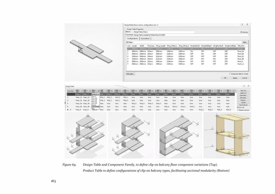
163
Figure 69. Design Table and Component Family, to define clip-on balcony floor component variations (Top),
Product Table to define configurations of clip-on balcony types, facilitating sectional modularity (Bottom)
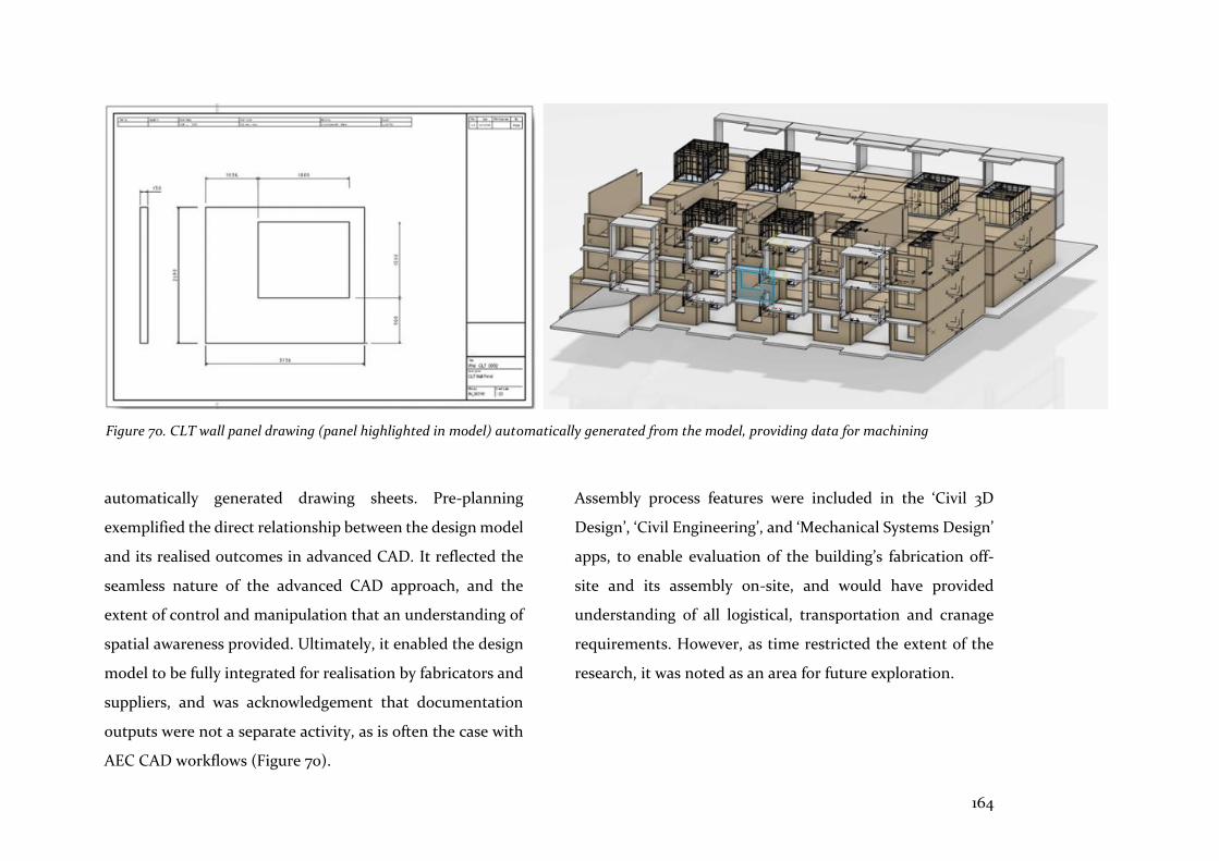
164
automatically generated drawing sheets. Pre-planning
exemplified the direct relationship between the design model
and its realised outcomes in advanced CAD. It reflected the
seamless nature of the advanced CAD approach, and the
extent of control and manipulation that an understanding of
spatial awareness provided. Ultimately, it enabled the design
model to be fully integrated for realisation by fabricators and
suppliers, and was acknowledgement that documentation
outputs were not a separate activity, as is often the case with
AEC CAD workflows (Figure 70).
Assembly process features were included in the ‘Civil 3D
Design’, ‘Civil Engineering’, and ‘Mechanical Systems Design’
apps, to enable evaluation of the building’s fabrication off-
site and its assembly on-site, and would have provided
understanding of all logistical, transportation and cranage
requirements. However, as time restricted the extent of the
research, it was noted as an area for future exploration.
Figure 70. CLT wall panel drawing (panel highlighted in model) automatically generated from the model, providing data for machining
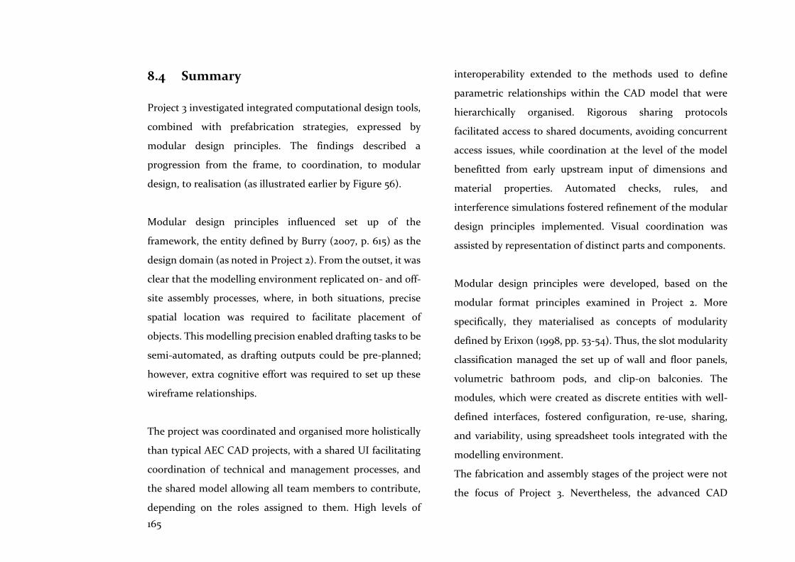
165
8.4 Summary
Project 3 investigated integrated computational design tools,
combined with prefabrication strategies, expressed by
modular design principles. The findings described a
progression from the frame, to coordination, to modular
design, to realisation (as illustrated earlier by Figure 56).
Modular design principles influenced set up of the
framework, the entity defined by Burry (2007, p. 615) as the
design domain (as noted in Project 2). From the outset, it was
clear that the modelling environment replicated on- and off-
site assembly processes, where, in both situations, precise
spatial location was required to facilitate placement of
objects. This modelling precision enabled drafting tasks to be
semi-automated, as drafting outputs could be pre-planned;
however, extra cognitive effort was required to set up these
wireframe relationships.
The project was coordinated and organised more holistically
than typical AEC CAD projects, with a shared UI facilitating
coordination of technical and management processes, and
the shared model allowing all team members to contribute,
depending on the roles assigned to them. High levels of
interoperability extended to the methods used to define
parametric relationships within the CAD model that were
hierarchically organised. Rigorous sharing protocols
facilitated access to shared documents, avoiding concurrent
access issues, while coordination at the level of the model
benefitted from early upstream input of dimensions and
material properties. Automated checks, rules, and
interference simulations fostered refinement of the modular
design principles implemented. Visual coordination was
assisted by representation of distinct parts and components.
Modular design principles were developed, based on the
modular format principles examined in Project 2. More
specifically, they materialised as concepts of modularity
defined by Erixon (1998, pp. 53-54). Thus, the slot modularity
classification managed the set up of wall and floor panels,
volumetric bathroom pods, and clip-on balconies. The
modules, which were created as discrete entities with well-
defined interfaces, fostered configuration, re-use, sharing,
and variability, using spreadsheet tools integrated with the
modelling environment.
The fabrication and assembly stages of the project were not
the focus of Project 3. Nevertheless, the advanced CAD
166
processes described above exemplified a seamless process, as
realisation outputs were built into the earliest stages of
setting up frameworks to define parts and components. Thus,
documentation and data outputs could be shared with
fabricators and suppliers throughout the design process.
In summing up the three projects detailed in Chapters 6, 7
and 8, it can be said that Project 3 demonstrated the synthesis
that AEC CAD tools and methods are clearly lacking. It
combined the intelligence exhibited by the GA in Project 1
with the logical methodology and robustness of an approach
that set up the framework of Project 2, and brought together
the best available tools and methods, thus coming closest to
the concept of an integrated computational design system.
This concept was implemented with the objective of
improving the way that prefabricated homes are designed
and produced.
These projects also demonstrated the distinction between the
notion of ‘test drive’ and the process of reflection-in-action.
A test drive compares similar products that have the same
function or goal, such as a car or the latest gadget. This is a
manufacturing concept that would be misapplied, as an
analogy, to the comparison or evaluation of tools aiming to
assist the design process. This is because most of the tools
used in the AEC sector have different objectives, and perform
different functions. Therefore, the visual programming graph
used in Project 1 cannot be compared with the advanced CAD
tool used in Project 3. As the research has demonstrated,
there is certainly no integrated tool or method that can
perform all the functions and objectives required of the
design and production process. Thus, in the face of
fragmentation and uncertainty, reflection-in-action takes the
place of the test drive, to uncover implicit assumptions, and
to reveal better solutions.
Chapter 9 (‘Discussion’) takes the notion of synthesis further.
There, following discussion of the findings of each project,
the MoI tool is applied to evaluate the level of integration of
each of the three projects. It highlights the steps that need to
be taken for particular projects to become integrated across
tools, methods, and participants. It is also offered as a means
to illustrate deficiencies, and to suggest solutions for the
integration of computational design tools in support of
everyday architectural design tasks, such as the improvement
of prefabricated homes.
167
The literature review, with its related, selective case studies
in Chapters 2 to 5, and the three projects which followed in
Chapters 6 to 8, tested the hypothesis of the research - that
integrated computational design tools combined with
compatible prefabrication techniques will lead to better
housing alternatives. This hypothesis further asserts that
solutions lie in more effective, user-friendly design and
production methods that will improve operability for
practitioners, and interoperability among participants. These
changes and solutions will result in better quality
prefabricated homes in Australia.
Integrated design tools and methods are essential if
production outcomes are to improve. Furthermore, systems
of designing and making are inter-linked, as they already
share concepts and goals that are compatible; however, a
better understanding of these synergies is required. More
effective integrated tools and methods will facilitate
collaboration, the sharing of knowledge, and the re-use of
concepts and components (computational and prefabricated)
that work. An integrated design process will also provide
more certainty that design intentions will be achieved, that
data loss will be reduced, that the re-working of drawings
downstream will be eliminated, that fewer errors will occur,
and that design solutions will more closely match
participants’ intentions and desires. Consequently, with
participants working across domains in an integrated and
collaborative manner, the design and prefabrication of homes
would improve, as a broader variety of cost-effective, higher
quality solutions would be developed.
Therefore, this chapter’s goal is to assemble, in clearer
outline, the changes and solutions required to achieve
integration. It provides a precursor to Chapter 10 which
introduces the IM methodology for rating levels of
integration. In both these chapters, the MoI (first defined in
Chapter 2.3) is used as a guide for evaluation and assessment.
Its features and attributes are repeated below for ease of
reference.
Op Openness
Protocols, tools and methods utilised in combination
are independent of a particular supplier, but allow
interactions and exchange of feedback.
9 Discussion

168
I0 Interoperability
Protocols, tools and methods utilised in combination
are able to be interchanged without affecting the
functioning of the system, and without data loss or
errors. This includes the ability to share and re-use
knowledge from:
1. Multiple software platforms linked to component
and federated models that utilise common
exchange formats (IFC) or customised scripts
2. A single software platform with a single shared
model (e.g. PLM)
C Collaboration
1. Digital entities and participants are able to work
together to create or achieve objectives via a data
management system (e.g. Aconex) or PLM
platform.
2. Communication among operations and
participants is facilitated via partnering or IPD.
D Dynamic interaction
1. Weak but essential dynamic interactions occur
between tools, methods, and components, via
parametric relationships.
2. Intense dynamic interactions occur within tools,
methods, and components, via encapsulated
knowledge and intelligent feedback.
O Operability
1. Protocols, tools, and methods are operable (e.g.
effective, user-friendly), reliable (e.g. robust),
supportable, and maintainable.
2. Intelligibility and the cognitive burden are
proportionate to the task.
3. Affordance is appropriate i.e. ‘…the potential of
the technology to enable the assertive will of its
user’ (Kalay 2004, p. 476).
This chapter comprises evaluations of the findings of Projects
1, 2, and 3, and a summary section, as follows:
Project 1: Searching ‘intelligently’ for better
Project 1 assessed the effectiveness of GAs and their
contribution to design solutions. It also examined methods
to make them more intelligible and suited to the exigencies
of design workflows, making use of the intelligent assistance
they provide.
169
Project 2: Rigorous and flexible frameworks
Project 2 evaluated the nature of concepts that purport to aid
designers when setting up computational design frameworks,
and assessed the expression of design rules that aim to
improve the flexibility and intelligibility of these methods.
The shortcomings of some of these concepts and methods are
described, while the modular format, as a programming
concept, is perceived as extensible to prefabrication methods,
including the development of modular design principles.
Project 3: A modular design strategy
Project 3 attempted to combine intelligent methods with the
logical methodology and robustness of an approach that sets
up the framework of the computational design project. It
aimed to improve prefabricated home design using modular
design principles, utilising an advanced CAD platform that is
claimed (by its vendors) to be the most integrated CAD
system available to the AEC sector.
Summary
The integrated nature of the main features and attributes of
the tools and methods of the three projects is summarised.
Based on the findings of this discussion and the MoI, a rating
tool is proposed for the purpose of assisting with the
understanding and development of integrated computational
design methods and tools, combined with prefabrication
workflows. This rating tool is defined in more detail in
Chapter 10.
9.1 Searching ‘intelligently’ for better
The starting point for many design methods has been the notion that design is a process of searching for a solution that satisfies a given set of goals and constraints. (Kalay 2004, p. 17).
Project 1 examined a computational design tool that supports
and enhances architects’ endeavours to find better solutions.
The genetic algorithm, as described in Chapter 4.2, is one
example from the artificial intelligence tool box that
enhances the capabilities of parametric modelling; indeed,
parametric modelling has recently been described as ‘the
most primitive stage of artificial intelligence’ (Andia &
Spiegelhalter 2015b, p. 23). Thus, the GA is assessed according
to its utility as an integrated design tool, which includes the
degree of openness and dynamic interaction, but it is also
evaluated for its seemingly ‘intelligent’ capabilities.
170
9.1.1 Single trial - an overview
GAs have been shown to be robust and flexible as they search
large populations for optimal solutions; however, they are
also known to be hindered by the effect of constraints, and
can find too many criteria difficult to optimise (Deb 2011, p.
16; Kalay 2004, pp. 286-287). Nonetheless, the ‘single trial’ GA
optimisation provided an informed overview of design
solutions in the early stage of design development. This was
an optimisation strategy that searched across a single
generation of 100 individuals (population x 2), to limit run-
time and create a snap-shot of the optimisation process as a
whole. This enabled feedback for further design generation
or the adaptation of existing solutions and better
understanding of the performance characteristics of
solutions, and facilitated development of the more focussed
optimisation routine that followed. The single trial also
highlighted a small sample of better solutions for
configurations of modules, which assisted comparison of
environmental performance between Happy Haus’s series
types and, more generally, between Happy Haus’s modules
and existing Brisbane dwellings.
Relevant objectives (phenotype)
…evolutionary methods allow the designer to set target goals and input parameters and rules that act together to search the population for the best possible candidates and use that pool of candidates as an input to breed an even better solution. (Jabi, Grochal & Richardson 2013, p. 225)
The definition of the criteria or objectives and the constraints
that modify them, is a key task of the architect. This is an
occasion when tacit knowledge and experience assist, as
outputs need to be meaningful in the environmental and
spatial context of the design problem. Based on chosen
objectives, simulated analysis can provide any quantity of
weather data for the site; however, only some of it may be
relevant if those objectives are ill-chosen. The goal is for the
objectives’ fitness values to converge in the area of the Pareto
optimal front, where prediction of the performance of
optimal solutions is more probable. For the goal to be
meaningful the objectives have to be relevant to the design
problem—a decision that only the architect (not the
computer) can make. Although the first experiment of
Project 1 confirmed the view that the GA is essential for
dealing with potentially large solution spaces, it also
demonstrated that human evaluative input is essential once
optimal solutions have been provided by the GA. In
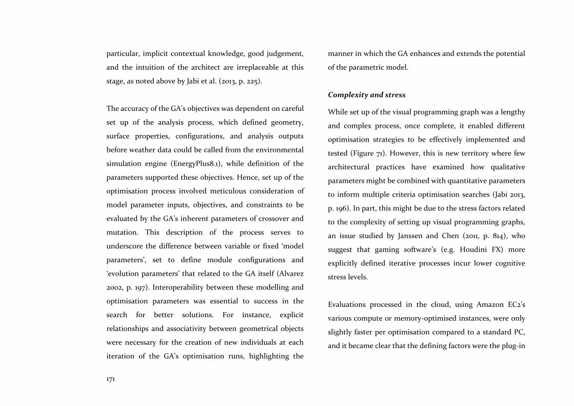
171
particular, implicit contextual knowledge, good judgement,
and the intuition of the architect are irreplaceable at this
stage, as noted above by Jabi et al. (2013, p. 225).
The accuracy of the GA’s objectives was dependent on careful
set up of the analysis process, which defined geometry,
surface properties, configurations, and analysis outputs
before weather data could be called from the environmental
simulation engine (EnergyPlus8.1), while definition of the
parameters supported these objectives. Hence, set up of the
optimisation process involved meticulous consideration of
model parameter inputs, objectives, and constraints to be
evaluated by the GA’s inherent parameters of crossover and
mutation. This description of the process serves to
underscore the difference between variable or fixed ‘model
parameters’, set to define module configurations and
‘evolution parameters’ that related to the GA itself (Alvarez
2002, p. 197). Interoperability between these modelling and
optimisation parameters was essential to success in the
search for better solutions. For instance, explicit
relationships and associativity between geometrical objects
were necessary for the creation of new individuals at each
iteration of the GA’s optimisation runs, highlighting the
manner in which the GA enhances and extends the potential
of the parametric model.
Complexity and stress
While set up of the visual programming graph was a lengthy
and complex process, once complete, it enabled different
optimisation strategies to be effectively implemented and
tested (Figure 71). However, this is new territory where few
architectural practices have examined how qualitative
parameters might be combined with quantitative parameters
to inform multiple criteria optimisation searches (Jabi 2013,
p. 196). In part, this might be due to the stress factors related
to the complexity of setting up visual programming graphs,
an issue studied by Janssen and Chen (2011, p. 814), who
suggest that gaming software’s (e.g. Houdini FX) more
explicitly defined iterative processes incur lower cognitive
stress levels.
Evaluations processed in the cloud, using Amazon EC2’s
various compute or memory-optimised instances, were only
slightly faster per optimisation compared to a standard PC,
and it became clear that the defining factors were the plug-in
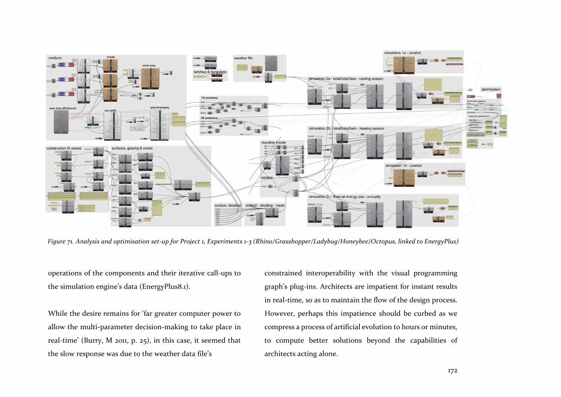
172
operations of the components and their iterative call-ups to
the simulation engine’s data (EnergyPlus8.1).
While the desire remains for ‘far greater computer power to
allow the multi-parameter decision-making to take place in
real-time’ (Burry, M 2011, p. 25), in this case, it seemed that
the slow response was due to the weather data file’s
constrained interoperability with the visual programming
graph’s plug-ins. Architects are impatient for instant results
in real-time, so as to maintain the flow of the design process.
However, perhaps this impatience should be curbed as we
compress a process of artificial evolution to hours or minutes,
to compute better solutions beyond the capabilities of
architects acting alone.
Figure 71. Analysis and optimisation set-up for Project 1, Experiments 1-3 (Rhino/Grasshopper/Ladybug/Honeybee/Octopus, linked to EnergyPlus)
173
Figure 72. Simple, Single and Micro GA operation processes and
settings, utilised by Project 1, Experiments 1-3
9.1.2 Simple GA - thorough but slow
An additional parameter and a focus on the environmental
performance of the Type 1 modules were the main differences
to the model parameters of Experiment 2. More significantly,
however, the simple GA’s evolution parameters were set to
optimise a larger population over a greater number of
generations, necessitating a lengthier optimisation run
(Figure 72).
Distance and indirection
The simple GA emphasised spatial, time, and
representational abstraction or separation between the
researcher and searches for solutions to the design problem.
Optimisation amplifies these levels of separation, as the
architect becomes the ‘maker of rules’ for both the model and
the algorithm (Jabi, Grochal & Richardson 2013, p. 225).
Although three views of each application (Rhino,
Grasshopper, Octopus) can be open while the optimisation
progresses, interaction is impractical and unnecessary at this
stage, as computations progress until completion, when the
results can be evaluated. Abstractions exemplified by the act
of set up, spatial, and time separation are levels of indirection
compounded by optimisation, a general characteristic of
computational design methods noted by Aish (2005, p. 11).
However, while physical separation between visual
programming graph and model facilitates deferral of design
decisions (as noted with Project 1), temporal separation due
to the GA’s operational mode has to be patiently accepted as
174
part of the computational design process for finding better
solutions, as noted above. However, as Kalay notes, too much
abstraction can hinder communication: ‘A high degree of
abstraction, therefore, makes communication more efficient,
though not necessarily more effective’ (Kalay 2004, p. 90).
Trust and commitment
Participants in the open source community of open,
integrated computational design tools are dependent on
support from plug-in developers, who, in the case of Project
1, are those who have created Octopus, Ladybug and
Honeybee. As Grasshopper and its plug-ins are free to
download, support is contingent in nature rather than
assured, and relies on trust that someone will be committed
to help, as no binding contract or transaction exists to compel
that commitment. The system seems to have worked for
Project 1 that stretched over a two-year period, as support was
always available. However, for large, complex, time-
consuming projects, firmer relationships of support and
greater reassurance might be accomplished by the open and
trust-based contractual relationships promoted by
‘partnering’ or Integrated Project Design (IPD). (As noted in
Chapter 1, these are management process changes outside the
scope of this research.)
Spreadsheets not models
With Project 1, when the quantity of data outputs increased
as optimisation run-time increased, spreadsheets (Excel)
became the means to collate and organise this data. From the
spreadsheets, more detailed human-directed evaluations and
decisions could be made; however, their parametric
capability and visual clarity were an essential part of the
optimisation process.
9.1.3 Micro GA efficiency
Indeed, there is an important sense in which a good theory defines the objects with which it deals. It reveals their interactions, the methods of transforming and controlling them, and predictions of what will happen to them. (Holland 1992, p. 2)
Experiment 3 also used the same model parameters as the
previous experiments. However, the evolution parameters
changed significantly in accordance with the setting
requirements for a micro GA that enables convergence
towards Pareto front solutions at a quicker rate than the
simple GA (Figure 72).
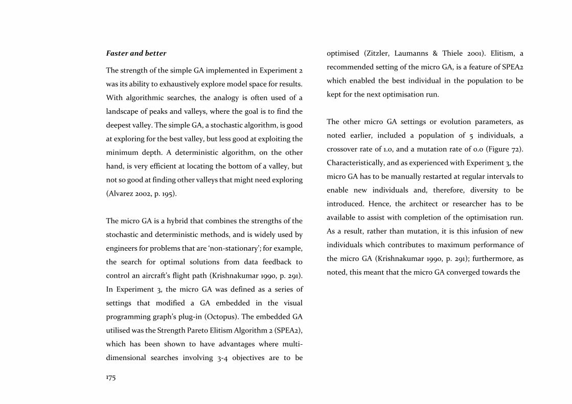
175
Faster and better
The strength of the simple GA implemented in Experiment 2
was its ability to exhaustively explore model space for results.
With algorithmic searches, the analogy is often used of a
landscape of peaks and valleys, where the goal is to find the
deepest valley. The simple GA, a stochastic algorithm, is good
at exploring for the best valley, but less good at exploiting the
minimum depth. A deterministic algorithm, on the other
hand, is very efficient at locating the bottom of a valley, but
not so good at finding other valleys that might need exploring
(Alvarez 2002, p. 195).
The micro GA is a hybrid that combines the strengths of the
stochastic and deterministic methods, and is widely used by
engineers for problems that are ‘non-stationary’; for example,
the search for optimal solutions from data feedback to
control an aircraft’s flight path (Krishnakumar 1990, p. 291).
In Experiment 3, the micro GA was defined as a series of
settings that modified a GA embedded in the visual
programming graph’s plug-in (Octopus). The embedded GA
utilised was the Strength Pareto Elitism Algorithm 2 (SPEA2),
which has been shown to have advantages where multi-
dimensional searches involving 3-4 objectives are to be
optimised (Zitzler, Laumanns & Thiele 2001). Elitism, a
recommended setting of the micro GA, is a feature of SPEA2
which enabled the best individual in the population to be
kept for the next optimisation run.
The other micro GA settings or evolution parameters, as
noted earlier, included a population of 5 individuals, a
crossover rate of 1.0, and a mutation rate of 0.0 (Figure 72).
Characteristically, and as experienced with Experiment 3, the
micro GA has to be manually restarted at regular intervals to
enable new individuals and, therefore, diversity to be
introduced. Hence, the architect or researcher has to be
available to assist with completion of the optimisation run.
As a result, rather than mutation, it is this infusion of new
individuals which contributes to maximum performance of
the micro GA (Krishnakumar 1990, p. 291); furthermore, as
noted, this meant that the micro GA converged towards the
176
Pareto front at a faster rate than the simple GA. The chart
below compares the run times for each of the GA strategies,
incorporating the parameters recorded in the exercises
(Figure 73).
In the AEC setting, where modelling is driven by less rigorous
imperatives, the micro GA could be used more widely in the
early stages of design development. There, it provides faster
exploratory and exploitative searches than simple GAs, as
demonstrated with Experiment 3, thus partially mitigating
the waiting game for architects.
‘Intelligent’ and subtle
Computers must help not only by doing ordinary computing, but also by doing computing that exhibits intelligence. (Winston 1993, p. 3)
Nicholas Negroponte (1973) described an architecture
machine which is able to learn from, and support its users.
These machines currently exist and have enabled self-driving
cars, while the GA is one of the tools which exhibit this ability
to learn. However, Negroponte suggests something more in
saying that: ‘given a form, generate the criteria… learn from
the criteria and someday generate new forms’ (Negroponte
1969, p. 12). His proposition could soon be a tool for use by
architects if the GA is combined with an artificial neural
network (ANN) so that its strength in producing unexpected
solutions is matched with the ANN’s ability to ‘evaluate
solutions in nonprocedural ways’ (Kalay 2004, p. 292).
Integration of design and production in the AEC sector needs
integrated technological tools that will improve
interoperability and interaction among participants. The GA
utilised for Project 1 is one of the tools that will contribute to
integration, and comes closer to Mitchell’s proposition that
‘commensurably subtle instruments’ in a declarative format
should be part of the creative design process and its CAD
support systems (Mitchell 1989, p. 14).
Figure 73. Comparison of GA strategy run-times (Gen = generations; Pop = population; RT
= run-time [in minutes])
177
9.2 Rigorous & flexible frameworks
Project 2 focused on set up of the design domain, the
architect’s introduction to the rigour and flexibility required
of the computational design process. The project revealed
limitations, challenges, and opportunities for improving
integration of design and production processes.
9.2.1 Whole and partial design domains
The design domain of the whole model was set up
conventionally, while the design domains of its parts were set
up computationally. This was designed to highlight and
examine differences between these approaches, their relative
ease of use, and operability. The conventional design
approach used implicitly defined objects and processes, while
the computational design approach employed explicit
definition.
As the initial expression of the dynamic and hierarchical
characteristics of a complex artificial system, the concept of
‘the design domain’ is fundamental in establishing an
understanding of the whole in relation to its parts. Therefore,
it is a concept which addresses recommendations that such
complexity should be decomposed into functional parts to
aid understanding, and in a manner that allows each
component to be designed independently of others (Simon
1996, p. 128). The design domain utilises abstract design rules
to define relationships, a technique first devised by
Sutherland with Sketchpad (1963). Furthermore, it is the
format of these design rules, and their manner of expression,
that can hinder or assist understanding. Explicit expression
assists, while implicit expression hides, or even obfuscates,
understanding. As demonstrated with Project 2, AEC CAD
allows predominantly implicit expression of these design
rules, with limited implementation of explicit expression,
thus hindering full understanding of the nature of
relationships between parts and the whole.
If architects are to improve integration of their craft’s
methods and tools, then explicit expression of these
relationships using computational design principles is
essential. Additionally, it has been observed that reflection on
these relationships fosters the notion and practice of
seamlessness between computational design and realisation
methods, where the computed part and the assembled part
are considered to be the same object (Retsin 2016, p. 145).

178
Partial design domains: a bottom-up approach
It was also asserted during set up of Project 2 that the design
domain is not one entity but many related entities, a
condition which reveals wider implications for interaction
and interoperability among components and assemblies. As
noted in Chapter 3, the idea of a single design domain
emanates from manufacturing design processes rather than
architectural design processes, as implied by descriptions of
its nature as ‘control rig’—a tool designed by the designer as
a formalised and externalised design process—or the ‘jig’, an
abstract framework isolating structure and spatial location
from geometric detail (Aish 2005, p. 11; Woodbury, Aish &
Kilian 2007, p. 223). These are top-down, holistic conceptions
of set-up, where, as stated above, a bottom-up, ‘nearly-
decomposable’ conception is needed—one which
acknowledges partial design domains applicable to parts and
sub-assemblies, where characteristics of openness and
interchangeability are fundamental (as noted in Chapter 2.3).
Set up of floor and wall panels for Project 2 demonstrated the
notion of these partial design domains, and, although
implemented by the constrained capabilities for explicit
expression of design rules using AEC CAD, it clearly
illustrated their ability to encapsulate understanding and
awareness of relationships and constraints.
9.2.2 Associative programming challenges
Design rules expressed using associative programming, as
represented by the visual programming graph’s UI, have been
described as ‘the principal technical obstacle to further
practical use’ (Aish & Woodbury 2005, p. 154). This
description was corroborated by Project 2, where physical
and visual distance between the graph’s and model’s UIs, and
abstract distance between expression of design intent and
design rules, led to levels of indirection which separated the
designer from interaction with the artefact, thus disturbing
design workflow and design thinking. However, this
abstraction of design rules is also advantageous, because
design decisions can then be revisited or deferred to later
stages (Aish & Woodbury 2005, p. 155). However, if architects
rely on other players to define explicit parametric
relationships or fall back on utilising AEC CAD’s implicitly
supplied objects and processes, they forego this advantage:
they are playing the role of secondary authors as ‘interactors’
with, rather than designers of, the game itself (Carpo 2011, p.
126).
179
Dealing with complexity
As Project 2 demonstrated, visual programming ‘does not
scale to more complex logic’ (Aish 2013, p. 88) or, by
extension, to more complex building assemblies. The
management of complexity itself is challenged by the UI’s
representation as the numbers of wires and nodes proliferate
in proportion to the increase in complexity. Combined with
errors in outputs and inconsistencies with nodal operation,
these factors undoubtedly deter architects’ engagement, and
lessen their assurance that design intent can be realised.
Solutions to manage complexity and support the acquisition
of more advanced computational design skills, have been
proposed by Aish (2013) and Janssen et al. (2016). They
suggest combining associative programming with imperative
textual programming that incorporates iterative looping and
higher order functions, a progression from ‘node to code’
(Aish 2013, p. 88). Perhaps, in this scenario, there is a role for
the ‘process engineer’, as proposed by Kieran and Timberlake
(2004, p. 7). However, as Fabian Scheurer notes, this ‘…adds
another layer of abstraction to the modelling problem’
(Schuerer 2012, p. 114). Hence, this strategy could be counter-
productive, presaging a greater hindrance to interaction.
Furthermore, while enabling a more complex task to be
carried out, this will not improve interoperability among
tasks, which is at the core of architectural workflows. The
visual programme is a ‘propagation based constraint system’
which progresses linearly using two algorithms—one for
ordering the graph and one for propagating values—while
the user’s task is to determine how particular relationships
are processed (Aish & Woodbury 2005, p. 154). This
description of its methodology highlights its focus—
computation of an instance—where, by contrast, the
architectural process concerns relationships among many
instances. Thus, the visual programme struggles to scale to
the size of a whole project with its myriad relationships,
which demand to be organised in a hierarchical manner to
address the relationship of parts to the whole.
In summary, associative programming enhances the
implementation of singular tasks and processes, but falls
short of improvements to interoperability and to
understanding of the whole. Computational design tools, to
be of use to architects, need to address these relationships,
and to consider complexity’s preferred and likely hierarchical
systemic organisation (as noted by Simon (1996, p. 184).

180
9.2.3 Modular format synergies
Understanding the nature of the modular format as a
building assembly method was assisted by early visualisation
of the hybrid prefabricated modules in relation to the whole
project, as implemented by simplified representations in the
AEC CAD tool. However, the underlying properties of these
components were hidden, which is evidence of the ‘trace’ or
‘style’ of the software (Carpo 2011, p. 100). Indeed, as Terzidis
observes, ‘…the designer’s work is at risk of being dictated by
the language-tools they use’ (Terzidis 2006, p. 58).
Consequently, part to whole relationships were obfuscated by
the terms ‘component’ applied to an indistinct, indiscrete
entity, and ‘part’ applied to an undivided, integral layer in the
‘system family’ of the AEC CAD tool.
An alternative method enabled explicit formation of
parametrically associated wall and floor components by
creation of templates that encapsulated design intent so that
interactions could be better understood. Accordingly, this
computational design method enabled the modular nature of
the components to be explored more fully.
Prefabrication and programming concepts
Further investigation of synergies between programming
concepts of modular design and prefabrication concepts of
modular design, suggested their commonalities in the notion
of ‘module’, but inconsistencies in their notion of ‘interface’.
The aim of the interface of the prefabrication module was to
achieve maximum, average, or minimum coupling depending
on location, as depicted in Project 2, Figure 14. The aim of the
programming interface (across which services are provided
by coded modules), on the other hand, is to consistently
achieve loose or minimum coupling. However, domain
engineering—a process where optimisation trades off
numbers of types of modules against the complexity of
interfaces as numbers increase—is a requirement common to
both fields, and a method deserving more attention in the
context of prefabrication. Thus, a starting point for
investigation might be Bemis’s 4-inch modular cube of the
1930s (noted in Chapter 5.1), which demonstrated extreme
complexity due to the large number of interfaces as a
consequence of a small number of types.
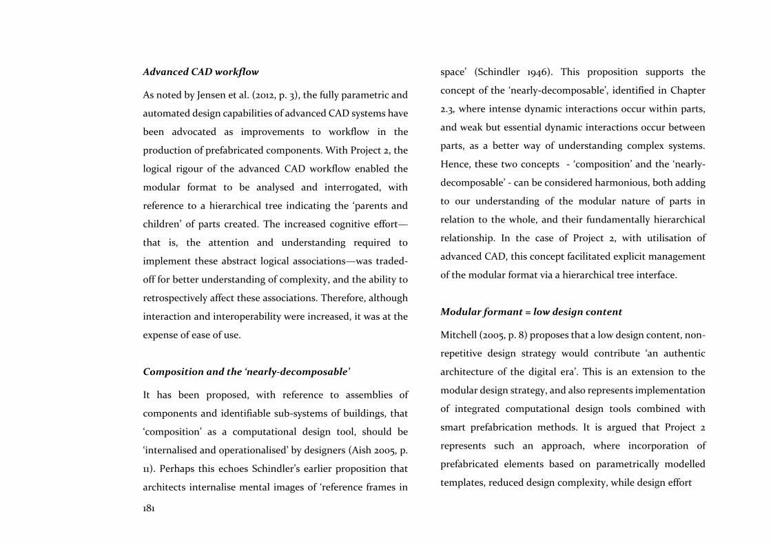
181
Advanced CAD workflow
As noted by Jensen et al. (2012, p. 3), the fully parametric and
automated design capabilities of advanced CAD systems have
been advocated as improvements to workflow in the
production of prefabricated components. With Project 2, the
logical rigour of the advanced CAD workflow enabled the
modular format to be analysed and interrogated, with
reference to a hierarchical tree indicating the ‘parents and
children’ of parts created. The increased cognitive effort—
that is, the attention and understanding required to
implement these abstract logical associations—was traded-
off for better understanding of complexity, and the ability to
retrospectively affect these associations. Therefore, although
interaction and interoperability were increased, it was at the
expense of ease of use.
Composition and the ‘nearly-decomposable’
It has been proposed, with reference to assemblies of
components and identifiable sub-systems of buildings, that
‘composition’ as a computational design tool, should be
‘internalised and operationalised’ by designers (Aish 2005, p.
11). Perhaps this echoes Schindler’s earlier proposition that
architects internalise mental images of ‘reference frames in
space’ (Schindler 1946). This proposition supports the
concept of the ‘nearly-decomposable’, identified in Chapter
2.3, where intense dynamic interactions occur within parts,
and weak but essential dynamic interactions occur between
parts, as a better way of understanding complex systems.
Hence, these two concepts - ‘composition’ and the ‘nearly-
decomposable’ - can be considered harmonious, both adding
to our understanding of the modular nature of parts in
relation to the whole, and their fundamentally hierarchical
relationship. In the case of Project 2, with utilisation of
advanced CAD, this concept facilitated explicit management
of the modular format via a hierarchical tree interface.
Modular formant = low design content
Mitchell (2005, p. 8) proposes that a low design content, non-
repetitive design strategy would contribute ‘an authentic
architecture of the digital era’. This is an extension to the
modular design strategy, and also represents implementation
of integrated computational design tools combined with
smart prefabrication methods. It is argued that Project 2
represents such an approach, where incorporation of
prefabricated elements based on parametrically modelled
templates, reduced design complexity, while design effort
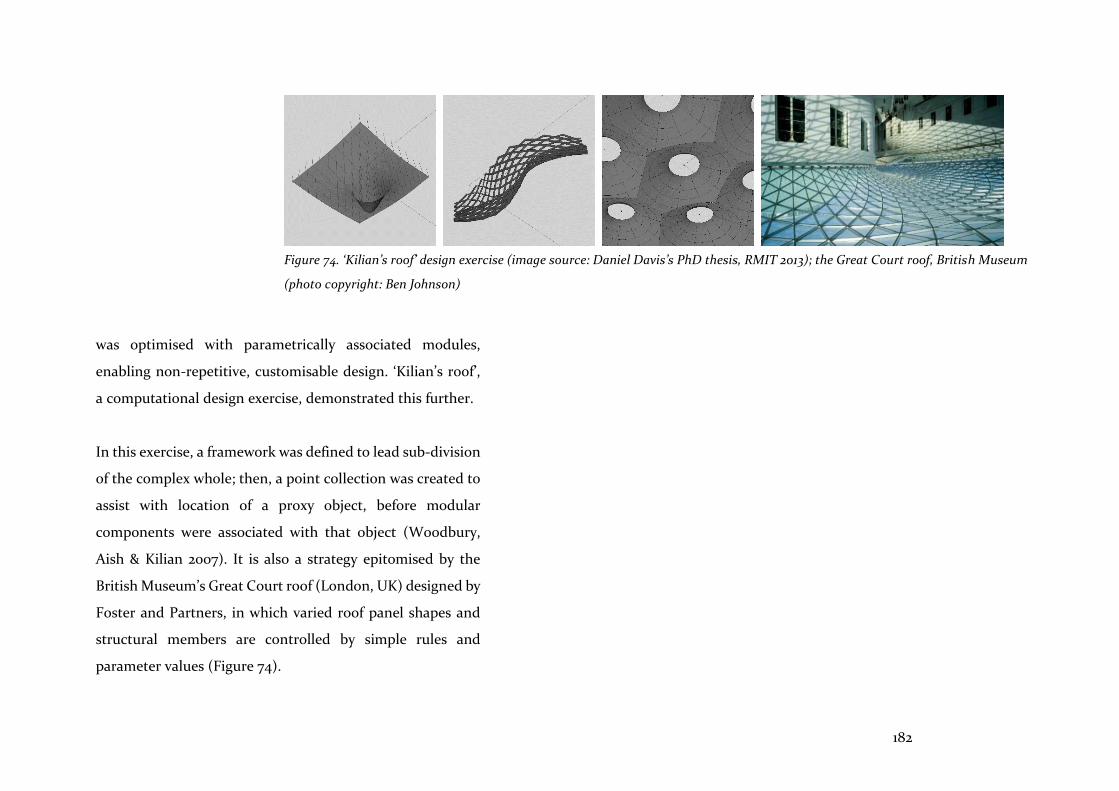
182
was optimised with parametrically associated modules,
enabling non-repetitive, customisable design. ‘Kilian’s roof’,
a computational design exercise, demonstrated this further.
In this exercise, a framework was defined to lead sub-division
of the complex whole; then, a point collection was created to
assist with location of a proxy object, before modular
components were associated with that object (Woodbury,
Aish & Kilian 2007). It is also a strategy epitomised by the
British Museum’s Great Court roof (London, UK) designed by
Foster and Partners, in which varied roof panel shapes and
structural members are controlled by simple rules and
parameter values (Figure 74).
Figure 74. ‘Kilian’s roof’ design exercise (image source: Daniel Davis’s PhD thesis, RMIT 2013); the Great Court roof, British Museum
(photo copyright: Ben Johnson)
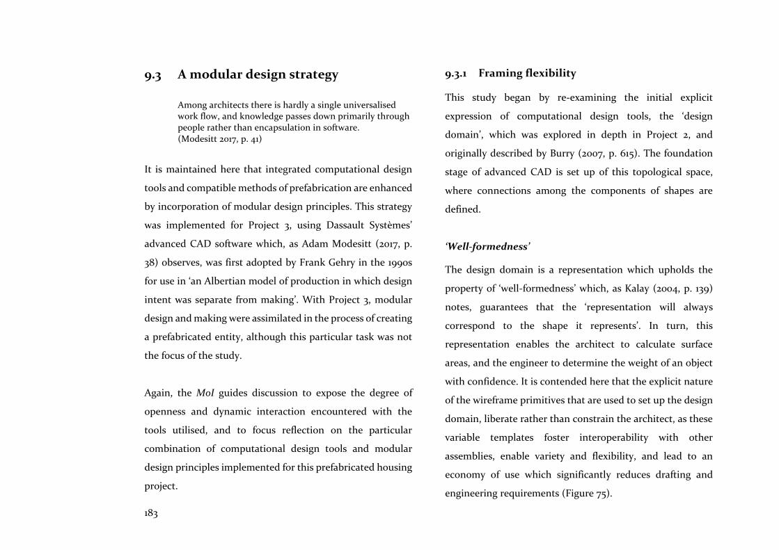
183
9.3 A modular design strategy
Among architects there is hardly a single universalised work flow, and knowledge passes down primarily through people rather than encapsulation in software. (Modesitt 2017, p. 41)
It is maintained here that integrated computational design
tools and compatible methods of prefabrication are enhanced
by incorporation of modular design principles. This strategy
was implemented for Project 3, using Dassault Systèmes’
advanced CAD software which, as Adam Modesitt (2017, p.
38) observes, was first adopted by Frank Gehry in the 1990s
for use in ‘an Albertian model of production in which design
intent was separate from making’. With Project 3, modular
design and making were assimilated in the process of creating
a prefabricated entity, although this particular task was not
the focus of the study.
Again, the MoI guides discussion to expose the degree of
openness and dynamic interaction encountered with the
tools utilised, and to focus reflection on the particular
combination of computational design tools and modular
design principles implemented for this prefabricated housing
project.
9.3.1 Framing flexibility
This study began by re-examining the initial explicit
expression of computational design tools, the ‘design
domain’, which was explored in depth in Project 2, and
originally described by Burry (2007, p. 615). The foundation
stage of advanced CAD is set up of this topological space,
where connections among the components of shapes are
defined.
‘Well-formedness’
The design domain is a representation which upholds the
property of ‘well-formedness’ which, as Kalay (2004, p. 139)
notes, guarantees that the ‘representation will always
correspond to the shape it represents’. In turn, this
representation enables the architect to calculate surface
areas, and the engineer to determine the weight of an object
with confidence. It is contended here that the explicit nature
of the wireframe primitives that are used to set up the design
domain, liberate rather than constrain the architect, as these
variable templates foster interoperability with other
assemblies, enable variety and flexibility, and lead to an
economy of use which significantly reduces drafting and
engineering requirements (Figure 75).
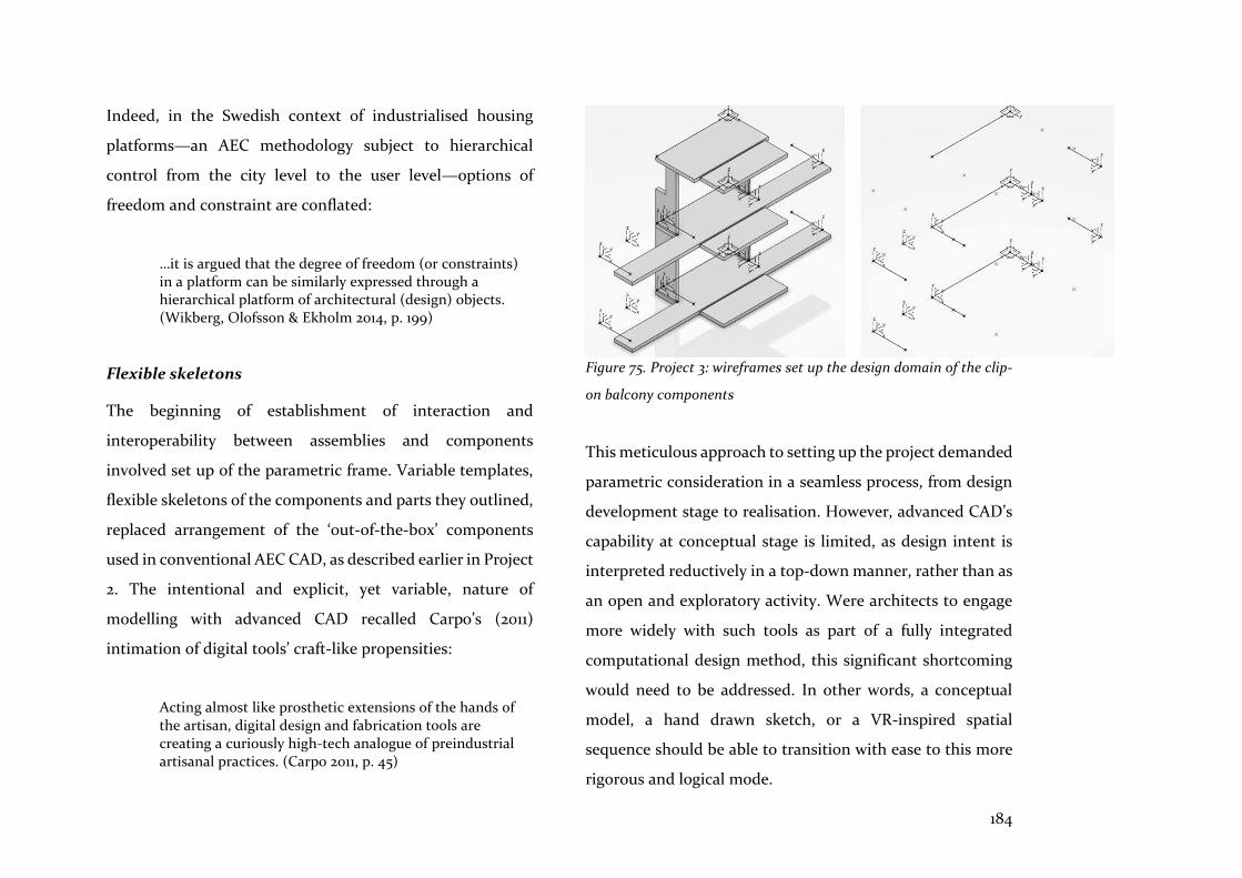
184
Indeed, in the Swedish context of industrialised housing
platforms—an AEC methodology subject to hierarchical
control from the city level to the user level—options of
freedom and constraint are conflated:
…it is argued that the degree of freedom (or constraints) in a platform can be similarly expressed through a hierarchical platform of architectural (design) objects. (Wikberg, Olofsson & Ekholm 2014, p. 199)
Flexible skeletons
The beginning of establishment of interaction and
interoperability between assemblies and components
involved set up of the parametric frame. Variable templates,
flexible skeletons of the components and parts they outlined,
replaced arrangement of the ‘out-of-the-box’ components
used in conventional AEC CAD, as described earlier in Project
2. The intentional and explicit, yet variable, nature of
modelling with advanced CAD recalled Carpo’s (2011)
intimation of digital tools’ craft-like propensities:
Acting almost like prosthetic extensions of the hands of the artisan, digital design and fabrication tools are creating a curiously high-tech analogue of preindustrial artisanal practices. (Carpo 2011, p. 45)
Figure 75. Project 3: wireframes set up the design domain of the clip-
on balcony components
This meticulous approach to setting up the project demanded
parametric consideration in a seamless process, from design
development stage to realisation. However, advanced CAD’s
capability at conceptual stage is limited, as design intent is
interpreted reductively in a top-down manner, rather than as
an open and exploratory activity. Were architects to engage
more widely with such tools as part of a fully integrated
computational design method, this significant shortcoming
would need to be addressed. In other words, a conceptual
model, a hand drawn sketch, or a VR-inspired spatial
sequence should be able to transition with ease to this more
rigorous and logical mode.
185
9.3.2 Closed integration: an incomplete solution
This advanced CAD system, although dynamically interactive
across and within its subsystems, was open to participants
only by subscription, while closed to alternative vendors’
software, except via neutral file exchange. The UI was present
in different contexts and formats at corporate, project, and
model level, managing complexity in alternative ways;
however, interoperability of this closed system was, by its
denial of access to other participants, incomplete. Other
Product Lifecycle Management (PLM) systems—including
Siemens NX and Windchill Creo—are similarly closed
integrated systems which are exclusively engineering
focussed.
‘Open integrated, advanced CAD’
Because the AEC sector’s CAD tools are increasingly
developed as open-source applications, an advanced CAD UI
needs to be framed differently to account for an open and
fragmented structure. For example, John Nastasi (Product-
Architecture Lab, Stevens Institute of Technology, NYC)
describes the ‘fluid desktop’, as ‘…a collective set of
interactive data that effects and is affected by any singular
adjustment’ (Nastasi 2012, p. 251). Project management
processes allowing full collaboration, interchangeability, and
dynamic flow between and within parts of the system are
essential if beneficial outcomes are to result. In an earlier age,
in the context of modular coordinated systems, Russell
expressed a similar but still relevant sentiment:
Using this open system in a responsive and responsible way can offer new and original results as well as drawing sensitively on tradition. (Russell 1981, p. 705)
Shared model, shared data
Nevertheless, a strength of closed integrated, advanced CAD
systems is that the exchange of data and communication
among participants is achieved by using a single, shared
model, as demonstrated with Project 3. This prevents data
loss and errors, as exchanges of text files and models only
occur within the single supplier’s system. By contrast,
organisation of complex AEC projects is often managed by
Aconex or FusionLive (formerly BuildOnLine) software; these
are both cloud-based, but without access to a single, shared
design model. Data loss and errors occurs during exchange,
leaving imported data as reference models that cannot be
edited. This prompted Schodek et al. to assert that ‘the need
for better mechanisms of data exchange is undisputed’

186
(Schodek et al. 2005, pp. 229). Presently, advanced CAD offers
the highest level of integrated file exchange.
Furthermore, the software UI of AEC design participants is
often dependent on the task in hand, and implemented and
expressed functionally by ‘geometric modellers’, ‘concept and
rendering modellers’, ‘animation modellers’, ‘entity based
modellers’, and ‘component based modellers’ (Schodek et al.
2005, p. 182). However, even within an architectural practice,
it is common for each designer to use a preferred design tool.
This is a decision based on political and social status, and
behaviour that is concerned with keeping control of the
design rather than its effective representation and
implementation, as observed by Loukissas in Keepers of the
Geometry (2009). Clearly then, this organisation of UIs across
AEC projects is the antithesis of an integrated approach.
Rather, the AEC sector should aim to match the assertion of
advanced CAD vendors that:
…the only approach that fully connects the data chain from start to finish…A Single Source of Truth is established, stored in a database on the cloud, and accessible by all project contributors through web services. (Systèmes 2014)
The main disadvantage of closed integrated systems is their
exclusion of all but subscribers to the software. Taking the
MoI as a guide, this exclusion would stifle innovation and the
ability for the system to adapt fully to its environment, in this
case, the AEC sector. For this reason, the MoI places a higher
value on openness and dynamic interaction—features which
von Bertalanffy’s (2008) System Theory included as evidence
of an all-encompassing doctrine of ‘wholeness’ (as noted in
Chapter 2). As noted with Project 3, it is also no longer the
case that sharing of data is hampered by concurrency
management, where two or more participants wish to work
on the same files. Advanced CAD systems have been
implementing these methods for decades, and an open,
integrated AEC CAD system could utilise such methods.
Parametric and operational interoperability
Interaction and operability between assemblies and
components were well supported by this closed integrated
system, but parametric set up is rigorous and time
consuming. With the modular design strategy, parametric
associations were established in complex relationships
between the whole and its parts, with a correspondingly
interrelated approach cultivated among the researchers to
187
ensure that modelling captured and developed the design
intent. However, in return for extra cognitive effort, varied
and flexible outcomes resulted, errors were reduced, and re-
use of knowledge and objects was maximised, contributing to
a more complete and fully coordinated design solution.
Dimensions, checks, rules and automation
Project 3 also demonstrated that early understanding of the
dimensions and properties of materials, and of modular
design strategies, aided by tools which check and monitor
relationships, is a pre-condition for maximising the
effectiveness of these tools and strategies. Checks reduced re-
work and errors, while strengthening the likelihood that a
resilient modular design strategy, where rules facilitated
manipulation of parametric variability and modular
configurations, would be created. Both features used EKL
programming language embedded with the model, which
was explicitly defined and, therefore, easily manageable. For
ease of communication, such high levels of abstraction using
imperative programming certainly depend on shared
knowledge among participants (Kalay 2004, p. 90). The EKL
textual programming language embedded in the parametric
modelling workflow represents a level of abstraction from the
design workflow but EKL is also an accessible and potent
design assistant which deals effectively with the complexity
of inter-relationships among associated parts. By contrast,
the recent addition of textual programming language to
visual programming graphs has created two levels of
abstraction, further distancing the architect from design
workflow.
Visual interaction, checking and correcting the model, were
continuous tasks. Self-contained, clearly defined components
facilitated this activity; however, automated checking of
clashes between components was fundamental, and would
have contributed to seamless progression of modelling
towards simulation of assembly, had this been the object of
study.
9.3.3 Modular design strategy
When a complex system is divided into smaller parts or modules, its complexity can be reduced. (Jensen, Olofsson & Johnsson 2012, p. 2)
A modular design strategy guided the prefabrication
methodology, which captured interoperability and
operability by utilising self-contained components with well-
188
defined interfaces. Scheurer (2012, p. 117) affirms the
necessity, at the outset, of defining interfaces, especially
when setting up a non-standard project. This is a theory and
application built into lean manufacturing processes.
However, in the AEC sector, challenges to its implementation
include the need to ensure that upstream flow of data from
engineers and fabricators reaches the design team early on.
However, prefabrication supports this approach, as
demonstrated by Project 3, where data was provided early on
via engineers involved with the AP14 case study, which
included materials’ structural and dimensional properties.
Open and interchangeable
A modular design strategy, which is open and integrated into
the computational design tool workflows, can also respond
more easily to the downstream flow of customer needs and
desires, compared to the fragmented tools and workflows of
the AEC sector’s present ‘silo-like’ organisation. Stehn &
Bergstrom (2002) note that consideration of components’ re-
usability and shareability can facilitate responses to upstream
flow and the pull of engineering and production processes (as
earlier mentioned in Chapter 5.3). Utilising this strategy as
part of an integrated design and production methodology,
the AEC sector could respond more effectively by identifying
appropriate types of modularity, and focusing on variations
of module types and their configurations. Such an approach
would allow flexibility and change at the manageable scale of
the module. This is defined in Project 3 as hybrid
prefabricated entities, including panellised floors and walls,
volumetric pods and clip-on balcony components.
Accordingly, it was noted (in Chapter 5) that the Swedish
home prefabrication industry uses modularisation as a key
constituent of their platform systems (Erixon 1998, p. 54).
Erixon’s study elucidated the notion of modularity,
describing modules as ‘chunks’ which encapsulate one or a
few functions, and which have well defined interactions with
other chunks (1998, p. 54). In the manufacturing sector,
modularisation is also considered a good method of
structuring products to manage variety. These properties of
modularity were tested in Project 3, and it is asserted that
they are effective methods for providing well defined
subsystems that contribute to clarification of the complexity
of the whole system. For this reason, consideration of floor
panels as cut-to-fit modules, rather than as elements without
clear boundaries—as would be the case with in situ concrete

189
floor slabs—complemented the computational design
technique of creation of a template which explicitly defines a
module’s parametric variables.
However, the purpose of this discussion as a whole is not to
evaluate modular design in isolation, but rather, as part of an
assimilated system of design and production. It is an
approach which embodies openness because the virtual and
physical modules or chunks can be exchanged, re-used and
shared as modelled or fabricated parts; hence, the
components designed for Project 3 exhibit the feature of
interoperability. However, in the MoI, while this feature is
applied to exchanges between software platforms, it is equally
applicable to exchanges between physical components. In
Chapter 5.2, this approach was contrasted with ‘integral
architecture’, a commonplace practiced in the AEC sector,
where boundaries between modules are either difficult to
identify or do not exist.
Configuration of spatial assemblies
An effective way of structuring self-contained yet variable
components is to utilise configuration—in this case, walls,
floors, bathroom pods and balconies assembled into the
whole. However, configuration is also a means to
communicate these arrangements of components to all
participants in the project, using only the model data
necessary for the particular participant, and taken from the
single shared model (Jensen, Olofsson & Johnsson 2012, p. 2).
This then allows the different advanced CAD ‘product views’
common to the manufacturing sector, which could be
applicable to the AEC sector: customer view; design and/or
engineering view; production view; and assembly view, as
defined by Malmgren et al. (2010, p. 358).
However, the configurational features of advanced CAD tools
should facilitate, rather than hinder, the architectural design
process, and be more user-friendly, as also noted by Jenson et
al. (2012, p. 7). With Project 3, configuration was confined to
the design and/or engineering view, primarily as a method of
structuring self-contained components, utilising Design
Tables, Component Families and Product Tables to assemble
parts. However, these configuration tools were oriented to
manufactured assemblies where self-contained parts are
made from primitive shapes that are added to or subtracted
from; assemblies of building components, on the other hand,
are usually one-offs made up of similar repeated parts with
190
spatial relationships, where the desire is to create variations
of the type. An open, integrated computational design tool
for the AEC sector would, therefore, address this issue, thus
facilitating variety and customisation through the
configuration of unique spatially defined, self-contained
components that make up modular assemblies.
9.3.4 Seamless realisation
Adoption of these platforms will not happen in AEC overnight…Uptake will require a restructuring of supply chains, an overhaul of contractual arrangements, a transformation of design and construction practices, and perhaps even developments in artificial intelligence. (Modesitt 2017, p. 40)
In this study, realisation received less focus than the frame,
coordination, and modular design, as steps in the design and
production methodology proposed, and as illustrated in
Figure 56, Chapter 8. However, realisation—or prefabrication
and assembly—was never absent from consideration because
it was anticipated during these earlier steps, and noted
accordingly. With the advanced CAD system utilised for
Project 3, realisation is part of a seamless process, in contrast
to current AEC CAD practice, and to practice in the AEC
sector in general.
9.4 Summary
In this discussion, the findings of each project have been
assessed, guided by the MoI, which has focussed on the
features and attributes of computational design tools, utilised
alongside compatible prefabrication methods. These
assessments are summarised below.
With Project 1, the practice of applying the GA encouraged
open collaboration, as it promoted the sharing and
communication of data and intelligence across participants,
to determine the relevant criteria for evaluation. The initial
creative input of the architect was subject to a trial of fitness,
as many alternative design solutions were generated and
tested by the evolutionary parameters of reproduction, cross-
over, and mutation. However, all participants needed to
carefully hone the objectives that directed this search for
better solutions, to ensure contextually meaningful and valid
outputs. The GA derived its potency and effectiveness from
the high degree of interoperability with the parametric
model, and the simulation engine. The operability of the GA
itself required knowledge of algorithmic and evolutionary
search processes, but revealed similarities with architects’
own searches for better solutions. The fact that the GA
191
offered more and better solutions than the architect could
find, made it a valuable computational design tool which
certainly assisted with providing more effective prefabricated
volumetric home solutions.
Set up of the design domain in Project 2 emphasised the
necessity to improve the expression of design rules. For
instance, it was clear that the concept of the design domain
needed to include partial domains, which established the
openness of relationships between the whole model and its
parts. As an expression of design rules, associative
programming improved intelligibility for a single task, rather
than a holistic design exercise. For example, while the task of
automated panel placement succeeded, the concurrent task
of setting up the panels with fixed and variable parameters
would have extended the visual programming graph’s
capability. However, the modular format, as an expression of
design rules, encouraged openness and interchangeability
between parts. Furthermore, it is an extensible concept,
applicable to building assembly methods, which likewise aim
for distinct components with well-defined interfaces.
The hybrid prefabrication strategy of Project 3 was
underpinned by the concept of modular design.
Implementation of this concept used an advanced CAD
system, demonstrating how effectively fully integrated
computational design tools assimilate with compatible
prefabrication methods. Collaboration and
interchangeability of knowledge created by the project was
wholly supported by a sophisticated UI, which included a
shared model. This also facilitated interoperability between
participants and the components of the shared model. As no
files were exchanged with other platforms, no data was lost,
and errors and inconsistencies within the shared model were
investigated and rectified. However, the modelling process
was cognitively rigorous and challenging. Furthermore, the
significant benefits noted were only available to subscribers
of the software platform.
These assessments have refined understanding of the nature
of methods and tools that foster integration of design and
production tasks. This development, in turn, prompts a
proposal for a tool that synthesises this understanding, and
enables measurement of the degree of integration of a
project, method, or tool. This proposed tool uses the MoI as
the foundation of its development and is defined in more
detail in Chapter 10 which follows.

192
In 1963, Sutherland, utilising the resources of the
Massachusetts Institute of Technology (MIT) invented the
prototypical CAD system, ‘Sketchpad’. Although it did not
reflect or implement the integrated nature of architectural
design tasks, it marked the beginning of attempts to create
digital design assistants. Since then, the toolmakers of the
AEC CAD software companies, with their extensive
technological and material resources, have addressed
integration of design tasks and their participants' interactions
in a piecemeal manner. Thus, the technological solution to
integration is beyond the reach of this research project.
Nevertheless, this thesis, having examined the deficiencies
noted above, proposes a brief to the toolmakers. This brief is
in the form of a rating methodology that evaluates the
Measure of Integration (MoI) of a particular tool, method, or
project and that, by inference, suggests what is needed to
foster more effective, integrated modelling systems.
This chapter’s goal is to synthesise the hypothesis of this
research by evaluating the findings of Projects 1, 2, and 3 in
accordance with the MoI, and by proposing a methodology
which rates the level of integration of computational design
methods and tools, and the projects for which they are
implemented. A rating tool termed Integrated Modelling (IM)
is proposed, and the methodology describing its goals,
purpose, operation, and limitations are described below. The
projects themselves are then assessed and rated.
10.1 Methodology
10.1.1 Purpose
The purpose of IM is to assist with the understanding and
development of integrated computational design and
production methods and tools. Projects 1-3 implemented the
three tasks of set up, optimisation, and modularisation.
However, each task comprised 3-4 experiments which
utilised different combinations of CAD and computational
design tools. The integrated nature of the methods and tools
used to implement these exercises, and of the projects
themselves, is rated. The goal is for these ratings, and the
graphical diagrams which represent them, to enable
comparison of the different methods and tools used to
implement each task, and to facilitate speculation regarding
the means to improve these ratings.
10 Integrated modelling
193
10.1.2 Operation
IM aims to achieve full integration, which incorporates full
collaboration as well as the other features and attributes
defined by the MoI. ‘Fully integrated’ means that AEC
methods and tools necessary for the implementation of AEC
design and production tasks are included. Thus, if the system
used incurs data loss and errors, and requires re-drafting
following exchange of data, it is not fully integrated. If the
methods and tools are unintelligible to those using them for
everyday tasks, or if they are incapable of defining
relationships between components and the model as a whole,
then they are not fully integrated. For example, the advanced
CAD system, a PLM platform, used in Project 3 approaches
BIM Level 3 compliance, but would fail the test of full
integration proposed here. This is because, not only is this
PLM closed to feedback and development from outside
sources, it does not link seamlessly to conceptual design
methods and tools.
Rating system:
Accordingly, IM rating Levels 0 to 3 are used to define
progressive levels of integration as follows:
Level 0 Zero integration
Level 1 Passive integration (e.g. separately integrated
or federated models)
Level 2 Active integration (e.g. partially integrated
models, or closed PLM systems)
Level 3 Full integration (e.g. comprising the features
and attributes of the MoI, an open and
dynamically interactive system)
Scoring system:
Codes defining the features and attributes of the MoI are used
to build up scores from which rating levels of 0-3 are
determined. All of the codes’ features are scored 0-6, and
each of the total scores of the sub-features of C, D and O are
equally weighted with Op’s and Io’s scores. Finally, the 5 main
codes are averaged to find the IM rating of 0-3 for each
exercise, and the total of these scores is then averaged to find
the overall IM rating for the project as a whole.

194
Op Openness
Io Interoperability
C Collaboration:
C1 Digital and physical entities
C2 Communication
between operations
and participants facilitated
D Dynamic Interaction:
D1 Interactions between
tools and methods
D2 Interactions within
tools and methods
O Operability:
O1 Reliable, supportable,
maintainable
O2 Intelligible, appropriate
cognitive burden
O3 Affordance of tool(s) is
appropriate
Spider diagrams. The features and attributes of each task were
appraised as a whole, and then scored according to the sub-
task or exercise, using the MoI as a guide. These scores were
entered into a spreadsheet which graphically depicted the
level of integration based on the scores’ intensity. The
spreadsheets utilised spider diagrams constructed around a
set of heuristic values which were derived from the MoI, while
the diagrams themselves indicated the intensity of
integration of that feature or attribute, which increased in
concentration away from the origin. Intensity was measured
on a scale of 0-6, ranging from absence, through degrees of
scarcity, to the concentrated intensity of the presence of
features and attributes. Through the identification of
patterns in the spider diagram, it is possible to highlight areas
of scarce integration or concentrated integration, revealing
the nature and impact of the features and attributes which
form the MoI. The resulting patterns facilitate speculation
about ways to increase integration to achieve better
solutions. For example, this might mean increasing the
openness of the task to allow wider cooperation between
participants, or it might mean focusing on the operability of
a particular tool or method.
Tasks, methods, and tools. Each project’s task is also
represented graphically according to the methods and tools
used to implement it. Often, because the task was broken

195
down into 2-3 exercises, there is overlap between methods
and tools, as described in Chapters 6 to 8. This overlap is most
noticeable for tasks implemented with open, integrated AEC
CAD tools. For tasks implemented with closed, integrated
PLM systems, such as advanced CAD, there is no overlap, as
all the methods and tools are contained in the closed system.
10.1.3 Limitations
The management changes which might influence the
heuristic values have not been considered in detail, as this is
outside the scope of the research. Nevertheless, it is tacitly
understood that implementation of partnering or Integrated
Project Delivery (IPD) would improve the code scores for
openness OP and collaboration C2, consequently increasing
the overall IM rating.
This study and assessments of the IM rating tools are also
influenced by the limited scope and scale of each project,
where the focus was on the design development stage of the
design and production process. Nevertheless, the earlier
conceptual and later realisation stages were taken into
consideration during evaluation of the findings (in Chapters
6 to 9), and are taken into consideration in these assessments.
Additionally, it is recognised that third party intersubjective
corroboration, including interviews with subjects about this
rating tool, is essential for a complete validation of its
effectiveness: this is noted as an objective of future research.
10.2 Project 1 - Searching for better
The main task of Project 1 was to search for better solutions
for the configuration of prefabricated volumetric homes.
These searches aimed to find low energy use options, and
focused on the heating and cooling season’s internal solar
heat gain. Open, integrated AEC CAD tools were used to
perform this task, which included several sub-tasks or
exercises incorporating the use of spreadsheets for
parametric modelling, visual programming, environmental
analysis, optimisation, and evaluations. These methods
overlapped with a variety of tools compiled to complete the
main task (Figure 76).
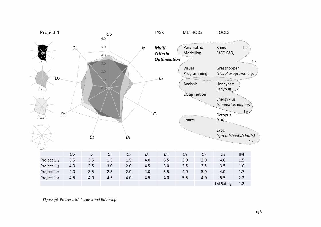
196
Figure 76. Project 1: MoI scores and IM rating
197
Op Openness
All the tools for this task were produced by independent
developers; nevertheless, their protocols, tools, and methods
facilitated their interaction. The researcher relied on
interaction and exchange of feedback with the developers of
the energy analysis plug-ins in particular; this was readily
available and helpful. All the tools had on-line forums for
exchange of feedback and debugging issues.
Io Interoperability
Exchanges of data and components among the AEC CAD
model, the visual programming graph and its add-ons, did
not impair the functioning of the system as a whole.
However, the data exchanged by the simulation engine with
these other components, significantly slowed the processing
and computation of optimal solutions (as noted in Chapter
6). Knowledge was shared across platforms without loss of
data during the exchange and, although real-time exchange
of data was slow, it depended on a firm foundation of
protocols and methods for sharing and re-use of this data. For
example, thermal data was transferred from the simulation
engine to plug-ins within the visual programming graph, and
this was then encapsulated as objectives to drive the GA’s
optimisation searches for better solutions, without data loss
during the process. Had there been more participants,
interoperability could have been enhanced with software
links to component and federated models.
C Collaboration
1. The digital entities facilitated a collaborative
workflow between the different suppliers’ platforms,
and this enabled objectives to be achieved. Although
collaboration among participants was not tested by
this task, it could have benefitted from
implementation of a data management system.
2. Communication between operations and participants
could have benefitted from a partnering or IPD
agreement.
D Dynamic Interaction
1. The intensity of interactions within these protocols,
tools, and methods was exemplified by parametric
relationships linking the nodes of the visual
programming graph to the simulation engine and the
GA of the multi-criteria optimisation method - all of
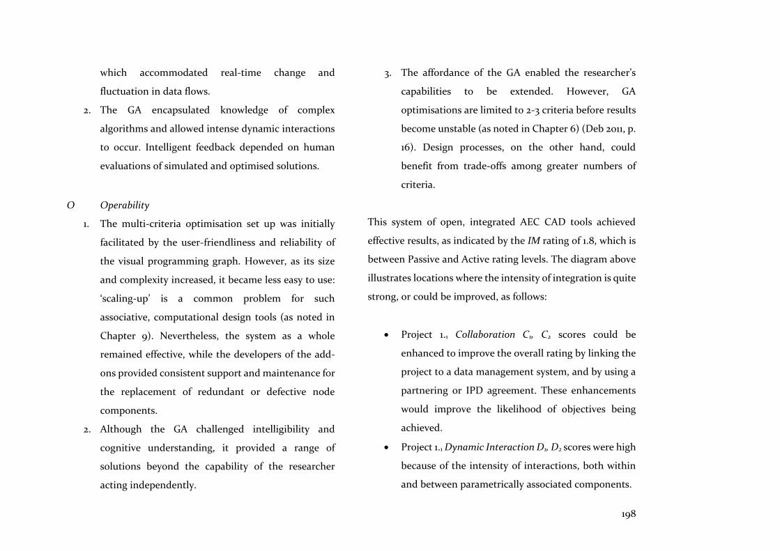
198
which accommodated real-time change and
fluctuation in data flows.
2. The GA encapsulated knowledge of complex
algorithms and allowed intense dynamic interactions
to occur. Intelligent feedback depended on human
evaluations of simulated and optimised solutions.
O Operability
1. The multi-criteria optimisation set up was initially
facilitated by the user-friendliness and reliability of
the visual programming graph. However, as its size
and complexity increased, it became less easy to use:
‘scaling-up’ is a common problem for such
associative, computational design tools (as noted in
Chapter 9). Nevertheless, the system as a whole
remained effective, while the developers of the add-
ons provided consistent support and maintenance for
the replacement of redundant or defective node
components.
2. Although the GA challenged intelligibility and
cognitive understanding, it provided a range of
solutions beyond the capability of the researcher
acting independently.
3. The affordance of the GA enabled the researcher’s
capabilities to be extended. However, GA
optimisations are limited to 2-3 criteria before results
become unstable (as noted in Chapter 6) (Deb 2011, p.
16). Design processes, on the other hand, could
benefit from trade-offs among greater numbers of
criteria.
This system of open, integrated AEC CAD tools achieved
effective results, as indicated by the IM rating of 1.8, which is
between Passive and Active rating levels. The diagram above
illustrates locations where the intensity of integration is quite
strong, or could be improved, as follows:
• Project 1.1 Collaboration C1, C2 scores could be
enhanced to improve the overall rating by linking the
project to a data management system, and by using a
partnering or IPD agreement. These enhancements
would improve the likelihood of objectives being
achieved.
• Project 1.1 Dynamic Interaction D1, D2 scores were high
because of the intensity of interactions, both within
and between parametrically associated components.
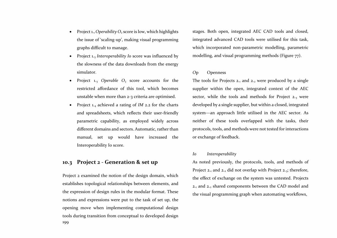
199
• Project 1.1 Operability O2 score is low, which highlights
the issue of ‘scaling-up’, making visual programming
graphs difficult to manage.
• Project 1.3 Interoperability Io score was influenced by
the slowness of the data downloads from the energy
simulator.
• Project 1.3 Operable O3 score accounts for the
restricted affordance of this tool, which becomes
unstable when more than 2-3 criteria are optimised.
• Project 1.4 achieved a rating of IM 2.2 for the charts
and spreadsheets, which reflects their user-friendly
parametric capability, as employed widely across
different domains and sectors. Automatic, rather than
manual, set up would have increased the
Interoperability Io score.
10.3 Project 2 - Generation & set up
Project 2 examined the notion of the design domain, which
establishes topological relationships between elements, and
the expression of design rules in the modular format. These
notions and expressions were put to the task of set up, the
opening move when implementing computational design
tools during transition from conceptual to developed design
stages. Both open, integrated AEC CAD tools and closed,
integrated advanced CAD tools were utilised for this task,
which incorporated non-parametric modelling, parametric
modelling, and visual programming methods (Figure 77).
Op Openness
The tools for Projects 2.1 and 2.2 were produced by a single
supplier within the open, integrated context of the AEC
sector, while the tools and methods for Project 2.3 were
developed by a single supplier, but within a closed, integrated
system—an approach little utilised in the AEC sector. As
neither of these tools overlapped with the tasks, their
protocols, tools, and methods were not tested for interactions
or exchange of feedback.
Io Interoperability
As noted previously, the protocols, tools, and methods of
Project 2.1 and 2.2 did not overlap with Project 2.3; therefore,
the effect of exchange on the system was untested. Projects
2.1 and 2.2 shared components between the CAD model and
the visual programming graph when automating workflows,
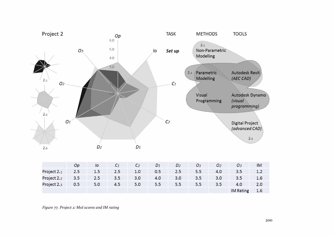
200
Figure 77. Project 2: MoI scores and IM rating
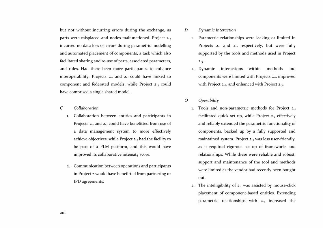
201
but not without incurring errors during the exchange, as
parts were misplaced and nodes malfunctioned. Project 2.3
incurred no data loss or errors during parametric modelling
and automated placement of components, a task which also
facilitated sharing and re-use of parts, associated parameters,
and rules. Had there been more participants, to enhance
interoperability, Projects 2.1 and 2.2 could have linked to
component and federated models, while Project 2.3 could
have comprised a single shared model.
C Collaboration
1. Collaboration between entities and participants in
Projects 2.1 and 2.2 could have benefitted from use of
a data management system to more effectively
achieve objectives, while Project 2.3 had the facility to
be part of a PLM platform, and this would have
improved its collaborative intensity score.
2. Communication between operations and participants
in Project 2 would have benefitted from partnering or
IPD agreements.
D Dynamic Interaction
1. Parametric relationships were lacking or limited in
Projects 2.1 and 2.2 respectively, but were fully
supported by the tools and methods used in Project
2.3.
2. Dynamic interactions within methods and
components were limited with Projects 2.1, improved
with Project 2.2, and enhanced with Project 2.3.
O Operability
1. Tools and non-parametric methods for Project 2.1
facilitated quick set up, while Project 2.2 effectively
and reliably extended the parametric functionality of
components, backed up by a fully supported and
maintained system. Project 2.3 was less user-friendly,
as it required rigorous set up of frameworks and
relationships. While these were reliable and robust,
support and maintenance of the tool and methods
were limited as the vendor had recently been bought
out.
2. The intelligibility of 2.1 was assisted by mouse-click
placement of component-based entities. Extending
parametric relationships with 2.2 increased the
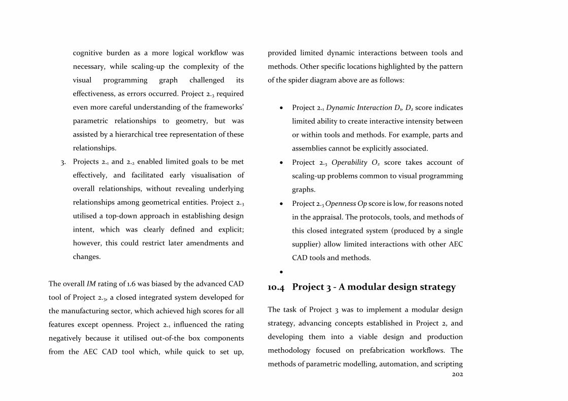
202
cognitive burden as a more logical workflow was
necessary, while scaling-up the complexity of the
visual programming graph challenged its
effectiveness, as errors occurred. Project 2.3 required
even more careful understanding of the frameworks’
parametric relationships to geometry, but was
assisted by a hierarchical tree representation of these
relationships.
3. Projects 2.1 and 2.2 enabled limited goals to be met
effectively, and facilitated early visualisation of
overall relationships, without revealing underlying
relationships among geometrical entities. Project 2.3
utilised a top-down approach in establishing design
intent, which was clearly defined and explicit;
however, this could restrict later amendments and
changes.
The overall IM rating of 1.6 was biased by the advanced CAD
tool of Project 2.3, a closed integrated system developed for
the manufacturing sector, which achieved high scores for all
features except openness. Project 2.1 influenced the rating
negatively because it utilised out-of-the box components
from the AEC CAD tool which, while quick to set up,
provided limited dynamic interactions between tools and
methods. Other specific locations highlighted by the pattern
of the spider diagram above are as follows:
• Project 2.1 Dynamic Interaction D1, D2 score indicates
limited ability to create interactive intensity between
or within tools and methods. For example, parts and
assemblies cannot be explicitly associated.
• Project 2.3 Operability O2 score takes account of
scaling-up problems common to visual programming
graphs.
• Project 2.3 Openness Op score is low, for reasons noted
in the appraisal. The protocols, tools, and methods of
this closed integrated system (produced by a single
supplier) allow limited interactions with other AEC
CAD tools and methods.
•
10.4 Project 3 - A modular design strategy
The task of Project 3 was to implement a modular design
strategy, advancing concepts established in Project 2, and
developing them into a viable design and production
methodology focused on prefabrication workflows. The
methods of parametric modelling, automation, and scripting
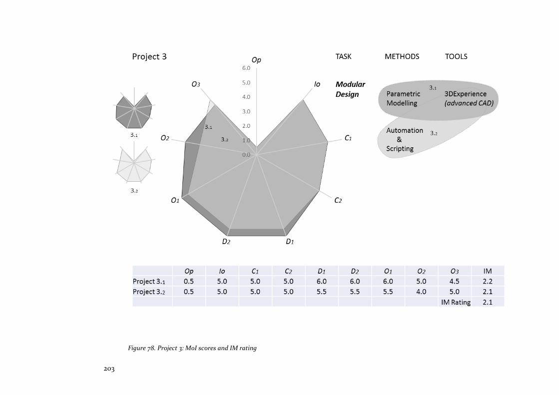
203
Figure 78. Project 3: MoI scores and IM rating
204
were all contained within the closed integrated system
employed; hence, no overlap occurred (Figure 78).
Op Openness
This Product Lifecycle Management (PLM) system operates
as a closed integrated platform; hence, all of its protocols,
tools, and methods have been developed by a single supplier.
Interactions and exchange with other vendors’ platforms
occur via common data exchange protocols, such as IFCs.
Io Interoperability
Protocols, tools, and methods were numerous, and
seamlessly exchanged within the closed system. Exchange
with other systems, and its effect on the whole system, was
not tested in Project 3. Tools and methods exchanged and
made use of intelligence and knowledge, without data loss or
errors. Several of the system’s features enabled instantiation,
and sharing and re-use of components at part and assembly
levels (as described in Chapter 8.3). A single shared model
facilitated interoperability between tools and methods.
C Collaboration
1. For Projects 3.1 and 3.2 the PLM operating in the cloud
enabled extensive collaborative management and
modelling among participants, to ensure that
objectives were met. A sophisticated ‘Dashboard’ UI
facilitated this process.
2. Communication and collaboration could have been
enhanced using a partnering or IPD agreement.
D Dynamic Interaction
1. Parametrically modelled templates and components
allowed comprehensive parametric relationships to
be established.
2. Tools and components containing values, formulas,
rules, constraints, and knowledge patterns, facilitated
intense dynamic interactions.
O Operability
1. While effective, these tools were developed for the
engineering domains; hence, manipulation of tools
and methods challenged the cognitive understanding
of this architecturally trained researcher. However,
the system is reliable, and well supported and
205
maintained in accordance with the expectations of
large manufacturing companies.
2. The tools and methods demanded logical thinking
processes, which were reflected in logical and
meticulous workflows. Also, modelling often
combined scripting in a seamless process to complete
tasks, demanding some knowledge of programming
rules and conventions.
3. Affordance. The tools’ capabilities were extensive,
reaching well beyond the ‘…assertive will’ of the
researcher. However, it is the realisation of the design
intent which is supported by the tools and methods,
rather than realisation arising from the earlier
architectural design stages of ideation or
conceptualisation.
The spider diagram highlights the overall intensity of
integration compared to Projects 1 and 2. This is because
Project 3’s tools and methods are the result of decades of
development and implementation, honed by the exigencies
of the automotive and aerospace industries in particular.
However, the pattern also shows the scarcity of intensity in
the region of openness, for the simple reason that a heuristic
value determines that openness achieves a higher intensity
score than ‘closedness’. Other locations of reduced intensity
indicated by the spider diagram include:
• Project 3.1. Collaboration C1, C2, values did not achieve
full intensity because the earlier stages of conceptual
design were not fully supported by the tools and
methods. Only the creation and achievement of
objectives from design development to realisation
could be the focus of collaborative working. Hence,
although Projects 1, 2 and 3 all focused on the later
stages, if partnering or IPD had been instituted at the
outset of the design process, it might have needed to
begin by utilising other AEC CAD tools.
• Project 3.2. Operability O1, O2 values indicate reduced
intensity scores due to the cognitive burden of
imperative scripting, a method which is frequently
used alongside parametric modelling tasks. While
this method increases the affordance of the tool, it
would necessitate extensive changes to architectural
education for it to become a familiar design process
for architects.
206
10.5 Summary
This chapter introduced and demonstrated use of the
Integrated Modelling (IM) rating tool, derived from the MoI
(introduced in Chapter 2.3), that aims to raise the level of
intensity of the integration of computational design methods
and tools used in the AEC sector. It does this by providing a
graphic depiction of the integrated status of protocols, tools,
and methods implemented for projects and tasks. From this
depiction, utilising spider diagrams, it is possible to speculate
about improvements to features and methods that would
increase the intensity of integration.
The methodology described the purpose of the rating tool, its
mode of operation, and its limitations. Heuristic values were
used to score the intensity of features and attributes, and
rated open and dynamically interactive systems more highly
than closed systems. This reflects a view, supported by
Simon’s notion of the ‘nearly-decomposable’ (described in
Chapter 2), that openness allows the optimal dynamic
interaction within a system. At the same time, it fosters the
likelihood of successful integration as no players are excluded
from contributing to its success. The value placed on
openness is also in response to the researcher’s perception of
the AEC sector, and the path it has taken to integrate its
protocols, tools, and methods. Indeed, the main feature of
this journey has been openness, where a plethora of suppliers
and developers have responded to the demands of the sector,
consequently needing to be able to work together in an
integrated and collaborative way to achieve goals and
objectives. In other words, as observed with the AEC sector’s
CAD systems, the IM tool reveals evidence of the trace of the
software and, in this case, also the researcher’s values and
opinions about the nature of the AEC sector.
This chapter’s goal was to synthesise the hypothesis of the
research by imagining, devising, and demonstrating the
notion of a fully integrated modelling system, its features and
attributes, and how projects might be appraised to reach
improved levels of integration intensity. The next
(concluding) chapter reviews the hypothesis and the
outcomes of this research, and draws together its broader
themes. It then examines the implications of a fully
integrated design and production environment for architects’
education and practice.
207
This conclusion draws on the evidence of the relevant
literature; the selective case studies; the findings of the
relevant project work; the Integrated Modelling (IM)
methodology; and the modular design strategy, to respond to
the main questions implied by the hypothesis, that integrated
computational design tools combined with compatible
prefabrication techniques will lead to better housing
alternatives:
• How will the integration of computational design
tools be achieved?
• How will it improve the design and production of
prefabricated homes?
• How will this integration affect architects’ education
and practice?
These questions and their solutions are related because the
integration of CAD tools utilised by architects in everyday
practice, combined with better strategies for designing and
making prefabricated homes, will assist in repairing the
dysfunctional and fragmented nature of the AEC sector.
11.1 How will the integration of
computational design tools be achieved?
The outcomes of the ratings of the IM tool (examined in
Chapter 10) do not suggest simple solutions. This is because,
as Kalay (2004, p. 475) observed, at least two paradigms that
affect the practice of architectural design and production are
created by these emerging tools and methods: first, the
misapplication or poor fit of tools; and second, changes to
practices and processes that are the result of the capabilities
of emerging tools. Nevertheless, the IM ratings of the tasks in
the three projects (documented in Chapter 10) facilitated the
investigation of these different paradigms, and feasible
solutions can be extrapolated. Therefore, these appraisals
demonstrate that solutions to integrating computational
design tools in the AEC sector are possible.
The AEC sector’s protocols, tools, and methods are as
fragmented as the sector itself. However, the IM tool has the
potential to assist in addressing this fragmentation. By using
this tool, it is possible to appraise a project’s integration
intensity by identifying weaknesses and strengths, enabling
further speculation about improvements and strategies to
improve the IM rating. By focusing on integration, this tool
11 Conclusion
208
goes to the heart of the AEC sector’s problems. As noted in
Chapter 1, BIM ranges across various management and
technical problems, with the aim of increasing efficiency; the
goal of the IM tool, on the other hand, is more specific: to
identify impediments to integration, and to appraise the
range of features and attributes that constitute fully
integrated systems.
A new integrated modelling system
A fully integrated design and production system would be
open: its protocols, tools, and methods would allow
interaction and exchange of feedback with other systems.
These exchanges would not adversely affect the integrated
modelling system, as full collaboration would be fostered by
access to Project Lifecycle Management (PLM) style
platforms, and partnering or Integrated Project Development
(IPD) agreements among participants.
Additionally, the integrated system would operate across a
single shared model, and its methods and tools would
embody intense dynamic interactions, with extensive
parametric and intelligent capabilities. Its interoperability
would allow seamless exchange of data without loss, and
would encourage the re-use and sharing of knowledge.
Protocols, tools, and methods would be effective, user-
friendly, reliable, and comprehensively supported and
maintained. Intelligibility and the intent of the designer
would be enhanced and extended by the affordance these
tools and methods provide.
However, participants in the AEC sector need to engage with
the changes to practice that are underway, to ensure a better
understanding of the way these changes are influenced by
these tools, and to also ensure that the tools are improved to
fit the tasks of design and production. To date, the core
participants in the AEC sector—that is, the clients, designers,
engineers, contractors and suppliers who have settled for
piecemeal improvements of their tools and methods—have
been neglectful. To be successfully and fully integrated, tools
and practices need shaping by their users so as to fit and
represent an open and dynamically interactive system.
11.2 How will it improve the design and
production of prefabricated homes?
Smarter ways of designing and making prefabricated homes
will emerge from integration, as symbiotic relationships

209
between tools and methods will be energised by this fully
integrated, interactive, and collaborative process. Integration
will connect design with production, thus reducing the cost
inefficiencies and waste inherent in fragmented and
dysfunctional AEC workflows.
Prefabrication
Prefabrication will benefit from smarter ways of designing
and making homes (as demonstrated by the modular design
strategy examined in Project 3). Through the use of
computational design methods, more and better design
options can be tested, simulated, optimized, and offered as
better solutions. As noted above, this will cast the architect
in the role of keeper of corpora of designs—all of which will
be quantitatively optimal, but still subject to qualitative
judgements arising from interaction with clients and other
participants.
A smarter method of prefabricating homes would incorporate
the modular design principles of modularity borrowed from
the programming and manufacturing sectors. These
principles acknowledge the distinctiveness of components,
and the particular types of interface encountered. They
represent an understanding of the properties of re-usability
and shareability, as noted by selected case studies of
successful examples from industrialised house building in
Sweden, and as implemented by Project 3 via a closed
integrated modelling environment. Utilising a modular
design strategy, the practice of design and the processes of
production can share compatible goals, mediated by
appropriate computational design tools, and resulting in
better quality outcomes.
Furthermore, a modular design strategy corresponds with the
integrated modelling goal of interoperability; that is, rather
than virtual protocols, tools, and methods, the physical
components themselves are interchanged without affecting
the functioning of the system, while also incorporating the
ability to share and re-use components. These features are
facilitated by the principles of ‘slot-modularity’—cut-to-fit,
component sharing, component swapping—as illustrated in
Chapter 8, Project 3. This project identified the component
interfaces, and their clear definition, as the key enabling
characteristic. Indeed, it is this setting up of the interfaces
that defines the difference between digital age non-standard
projects, and the standardised processes of the industrial age.
210
Notably, as with the selection of meaningful criteria as the
basis of multi-criteria optimisation, this set-up requires
careful, human consideration to succinctly describe the
template that forms the basis of a well-formed parametric
model.
In support of this notion of digital age non-standard projects
it is maintained that they are accommodated by an integrated
modular design strategy where the module is of variable scale
and where configurations are defined by interfaces such that
outcomes are numerous and varied. This contrasts with non-
modular projects which lack clear boundaries and interfaces,
and any ability to identify self-contained components or
entities, leading to any number of possible configurations.
This approach was described in Chaper 5.2 as ‘integral’
design, the prevailing form of production and construction in
the AEC sector.
Productivity, efficiency, costs, design and assembly time
Conspicuously, the construction industry suffers from poor
productivity and inefficiency, while its projects and costs
often overrun time and budget respectively. A key problem is
that the industry is highly fragmented, with project teams
often working in isolation on a project before moving on to
the next. This fragmentation adds to inefficiencies, and stifles
innovation. The prefabrication of components and
volumetric assemblies off-site promises faster project
delivery, improved quality and building performance, and
has the potential to lower costs. By adopting prefabricated
processes, which combine integrated computational design
and production tools and methods incorporating a modular
design strategy, the AEC sector will begin to transform the
way that the built environment is designed and constructed.
Furthermore, in a less risk averse, more settled, and more
integrated AEC sector, innovation will be encouraged and
facilitated.
If synergies between computational design tools and smarter
prefabrication strategies are acknowledged and understood,
integration will improve the design and production of homes.
Higher quality prefabricated homes will be produced because
computational design tools will be connected in a
streamlined flow from production, to fabrication, to
assembly.
211
11.3 How will this integration affect architects’
education and practice?
Computational design and production tools are already
beginning to change practice as workflows are
computationally assisted or improved by automation, and as
the authorial identity of the architect changes in keeping with
more interactive and collaborative work modes. Accordingly,
the training of architects needs to respond more energetically
to these changes to prepare architects for these new tools,
and these new ways of working. Most importantly, architects’
training should empower them to engage with the
toolmakers, embolden them to shape practice according to
their vision, and even to make the tools themselves.
Education
The effects of integration, and the implications of more
collaborative and interactive ways of working, need to be
introduced at the outset of architects’ training. The Product-
Architecture Lab (Stevens Institute of Technology, NYC), for
example, is the pioneer of an approach that is focused on
digital craft and material properties, while an emphasis on
collaborative workflows is at the core of Interdisciplinary
Design for the Built Environment (Cambridge University,
UK).
Different ways of thinking also need to be encouraged to
assist architects’ engagement with computational design
concepts and operations, and to facilitate discussion across
disciplines. However, these issues should not be addressed in
a subject that is separate from traditional design modes of
thinking; rather, they should be treated as a logical,
reasonable, and algorithmic supplement that is supportive of,
and extends, architectural intuition and imagination to make
more innovative and better buildings. Rather than being
form-focused, students would be process-focused—
encouraged to develop their digital craft expertise and their
understanding of material properties and propensities, while
engaged in collaborative and interactive discussions with the
disciplines that make buildings.
Interoperability is one of the biggest challenges to achieving
integrated design and project delivery. Therefore, the
emphasis would be on managing digital workflows between
platforms, by creating and encouraging open-sourced
software platforms that are able to exchange data and files
212
without loss or error. Ideally, this exchange would occur
across a single, shared model, and this would eventually
become the basis of the project contract for a partnering or
IPD agreement.
Practice
The role of architects will broaden as they become authors of
computational design rules. In this authoring process, they
will instill their intuitive and tacit knowledge, which will
begin to transfigure digital processes. Integration of
computational design tools will also advance architects’
removal from manual drafting and re-drafting tasks. Rather,
they will refocus on the authorship and management of
design rules that will incorporate their design values and
preconceptions.
However, rather than solely designing buildings, architects
will also be designing and managing design processes
themselves, ensuring that the flow of data is streamlined and
error-free. They could also become managers of design
outputs that are the result of optimisation processes that
generate solutions that satisfy design intent (as demonstrated
by Project 1). The artificial intelligence (AI) techniques at the
core of smart computational design tools, such as genetic
algorithms (GAs), will advance these changes. Intelligence
that is embedded in design workflows to define constraints,
design rules, parametric rules, and goals will also assist
architects as it reduces the likelihood of errors and
inconsistencies (as shown by Project 3). But, architects could
also take note of the wider range of design support systems
available. This research has focussed on design tools , but,
increasingly, more advanced forms of support will be
provided by semi-autonomous assistants (e.g. space
allocation programmes), and by software agents that can
respond to instructions and initiate actions: thus, the direct
manipulative techniques offered by AEC CAD tools will give
way to degrees of delegation based on ‘the ability of software
agents to automatically ascertain their users’ intentions and
take action based on a vague statement of goals ‘(Kalay 2004,
p. 439). With a shared understanding of computational
design procedures, this broader spectrum of tools and
methods will also nurture interdisciplinary relationships.
Practice will evolve in response to the technological pressures
and opportunities examined in this study. Integrated design
and production practices are already beginning to emerge,

213
and could be defined as specialists within large design
practices (e.g. SuperSpace, Woods Bagot, Sydney); as stand-
alone design assistants (e.g. Cadmakers, Vancouver); or as
embedded design services in fabrication practices (e.g. ShOP,
Architects and ShOP Construction, New York). These
distinct design specialists will be at the core of the digital
information exchange, pioneering new models of practice,
and defining a new industry. This industry will be less
recognized by an acronym that combines separate domains—
that is, AEC—and more as a single activity (yet to be named).
It will focus on the process of the design, making, fabrication
and assembly of buildings. Integration of computational
design tools and methods will transform practice,
production, workflows, efficiency, quality, cost, performance,
and communication. In this way, the AEC sector will be
brought into the digital age.
11.4 Summary
Schön observed in The Reflective Practitioner that architects
will have to function in radically new ways as a consequence
of ‘…new techniques of information processing in design’
(Schön 2008, p. 25). Accordingly, a significant aspect of the
research methodology involved project work that
incorporated ‘reflection-in-action’ in combination with ‘the
science of design’ (Simon 1996, p. 111). Reflection brings to the
surface tacit assumptions that are implicit in actions that deal
with situations of uncertainty and instability. This reflective
research method is also pertinent because architectural
practice has had little time for reflection on the utility and
practical implications of these emergent computational
design tools. Furthermore, the pace of change has not
allowed time for training in the use of these tools so that
architects of the future can fully engage with them. Hence,
this study contributes by reflecting on these issues during its
project work.
The Integrated Modelling (IM) tool synthesises a solution to
the question raised by the research hypothesis. It facilitates
change by highlighting deficiencies and weaknesses in the
intensity of the integration of protocols, tools, and methods
utilised for the implementation of design and production
tasks. In an open environment—where innovation,
interaction, and collaboration are intrinsic to the solutions
provided, and where tools and methods are created with
intensely dynamic and synergistic properties—integration is
facilitated and nurtured. IM assists with the search for better
214
ways of designing and producing prefabricated homes by
incorporating smarter and more intelligent means to reach
this goal. It can also help software companies, educators,
practitioners, and toolmakers, by providing them with a
framework and a brief around which to orient their efforts
towards integration.
Future research will focus on integration utilising the IM
rating tool, including intersubjective corroboration of the
implementation of computational design support systems
that enable indirect manipulation of design tasks. As noted
earlier, this includes assistants and agents that can respond
to instructions and initiate actions, while also facilitating
collaboration and interaction between participants (Kalay
2004, p. 418) This scenario envisages a less distinct role for
the design professional, both an imperative and an
opportunity recognised by design embedded fabrication
practice SHoP Architects and SHoP Construction (2007-
2015), as discussed earlier. Correspondingly, the contractor’s
role will be transformed by recognition that vertically
integrated companies involved with manufacturing and
development can spread risk more evenly, while feedback
from end-users can be built-in to design and production thus
leveraging full design value (Aitchison & Doe 2017, pp. 123-
124). Accordingly, as Kieran and Timberlake observe, the
contractor will become an assembler working between the
architect and the product engineer ‘to develop integrated
component assemblies’ (Kieran & Timberlake 2004, p. 47).
While everyday architectural design tasks might not change,
these emerging tools will nevertheless almost surely change
the practice of architecture. This is because architects’
cognitive flow has been stimulated by the digital flow of bits,
extending and improving their ability to contrive, order, and
settle the disparate parts of the design problem. While they
might still grapple with design problems by utilising age-old
paper-based protocols for their representation and
production, they now have additional processes to support
their task. Furthermore, the design process can now be
informed by an unimaginable number of computation-based
procedures, assimilated with smarter methods of
prefabrication. These new aids will ultimately improve
production processes in general, and prefabricated housing
solutions in particular.

215
Bibliography

216
First author papers:
Doe, Robert, and Mathew Aitchison 2015a,
‘Computational design of prefabricated modular
homes’, in MST Anderson (ed.), Proceedings of the 3rd
International Conference of Architecture and
Engineering (ACE), Singapore, pp. 648 - 654
Doe, Robert, and Mathew Aitchison. 2015b, ‘Multi-
criteria optimisation in the design of modular homes
- from theory to practice’, in B Martens, G Wurzer, T
Grasl, WE Lorenz, R Schaffranek (eds), Real Time -
Proceedings of the 33rd Annual Confrence of Education
Research in Computer Aided Design in Europe
(eCAADe15), Vienna, pp. 295 - 303
Doe, Robert, and Mathew Aitchison. 2016a,
‘Facilitating change: the design domain in
prefabricated home design’, in H Abdalla,
Abdelmohsen, A Barracco, G Retsin, MS Amer (eds)
Proceedings of Parrallelism in Architecture,
Environment and Computing Techniques (PACT),
London, pp. 258 - 268
Doe, Robert, and Mathew Aitchison. 2016b,
‘Facilitating change: the modular format in the design
of prefabricated homes’, in J Zuo, L Daniel, V Soebarto
(eds), Proceedings of the 50th International
Conference of the Architectural Science Association
(ASA), at Adelaide, pp. 397 – 406
Doe, Robert. 2018, ‘Facilitating integration of
computational design processes in the design and
production of prefabricated homes’, in Architectural
Science Review, vol 61, issue 4, pp. 246 - 254. Taylor &
Francis Online
Book chapter:
Aitchison, M, Doe, R, et al. 2018, Prefab Housing and
the Future of Building: Product to Process, Lund
Humphries, London.
Published works
217
Ackerman, JS 1983, Palladio, 2nd edn, The Architect and Society, Pelican Books, Harmondsworth, Middx. Afsari, K, Eastman, C & Shelden, DR 2016, 'Data transmission opportunities for collaborative cloud-based building information modelling', paper presented to XX Congress of the Iberoamerican Society of Digital Graphics, Buenos Aires. AIA 2007, Integrated Project Delivery: A Guide, The American Institute of Architects. Aish, R 1977, 'Prospects for Design Participation', Design Methods and Theories, vol. 11, no. 1, pp. 38-47. —— 2005, 'From Intuition to Precision', in JP Duarte, G Ducla-Soares & AZ Sampaio (eds), eCAADe 23, Lisbon, pp. 10-4. —— 2013, 'DesignScript: Scalable Tools for Design Computation', in eCAADe 31, Delft, vol. 2, pp. 87-96. Aish, R, Fisher, A, Joyce, S & Marsh, A 2012, 'Progress toward multi-criteria design optimisation using DesignScript with SMARTForm, Robot Sructural Analysis, and Ecotect buiding performance analysis', paper presented to ACADIA 2012. Aish, R & Woodbury, R 2005, 'Multi-level Interaction in Parametric Design', in B A, F B, K A & O P (eds), Smart Graphics. SG 2005. Lecture Notes in Computer Science, Springer, Berlin, vol. 3638, pp. 151–62. Aitchison, M & Doe, R 2017, Prefab Housing and the Future of Building: Product to Process, Lund Humphries, London.
Alberti, LB 1755, De Re Aedificatoria, De Pictura, De Statua, Edward Owen, London. Alexander, C 1964, Notes on the Synthesis of Form, Harvard University Press, Cambridge, MA. Alvarez, G 2002, Can we make genetic algorithms work in high-dimensionality problems?, Stanford University, Stanford, CA. Andia, A & Spiegelhalter, T 2015a, 'Automating Design via Machine Learning Algorithms', in Post-Parametric Automation in Design and Construction, Artech House, Boston, MA, pp. 191-9. —— 2015b, 'Automating What?', in Post-Parametric Automation in Design and Construction, Artech House, Boston, MA, pp. 17-33. Australian Government, DotE 2014, National Greenhouse Accounts Factors: Australian National Greenhouse Accounts, Australian Government, Canberra, <http://www.environment.gov.au/>. Banham, R 1960, Theory and Design in the First Machine Age, Architectural Press, London. Barlow, J, Childerhouse, P, Gann, DM, Hong-Minh, S, Naim, M & Ozaki, R 2003, 'Choice and delivery in housebuilding: lessons from Japan for UK housebuilders', Building Research & Information, vol. 31, no. 2, pp. 134-45. Bemis, AF 1936, 'Rational Design', in The Evolving House, MIT Press, Cambridge, MA, vol. 3.
Works cited
218
Bensonwood 2017, Unity House, Bensonwood, viewed 15 September 2017, <http://bensonwood.com/projects/unity-house/?portfolioCats=396>. BluHomes 2017, Blu Design Studio, BluHomes, viewed 12 September 2017, <https://www.bluhomes.com/design_studio/>. Branz & Environments, E 2010, AccuRate Sustainability: Greenhouse Performance Module Research, Australian Government, Canberra. Brito, ME, Lopes, RdOA, Rocha, L & Qualharini, L 2015, 'Beyond buildability: operability and commissioning of industrial facilities', paper presented to 29th World Congress International Project Management Association (IPMA), Panama. Broome, J 1986, 'Special Issue: the Segal Method', Architect's Journal, vol. 183, no. 45, pp. 31-68. Burnett, M & al, e 1995, 'Scaling up Visual Programming Languages', Computer, vol. 28, no. 3, pp. 45-54. Burry, J 2007, 'Mindful spaces: computational geometry and the conceptual spaces in which designers operate', International Journal of Architectural Computing, vol. 5, no. 4, pp. 611-24. Burry, J & Burry, M 2010, The New Mathematics of Architecture, Thames and Hudson, London. Burry, J, Burry, M, Tamke, M, Thomsen, MR, Ayres, P & al, e 2012, 'Process through practice: synthesizing a novel design and production ecology through Dermoid', in JK Johnson, M
Cabrinha & K Steinfield (eds), ACADIA 12, San Francisco, pp. 127-38. Burry, J & Holzer, D 2009, 'Sharing Design Space: remote concurrent shared parametric modeling', in eCAADe 27, Istanbul, pp. 333-40. Burry, M 2011, Scripting Cultures: Architectural Design and Programming, AD Primers, John Wiley & Sons Ltd., Hoboken, NJ. Caldas, L & Santos, L 2012, 'Generation of Energy Efficient Patio Houses with GENE_ARCH', in eCAADe 30, Prague, pp. 459-70. Carpo, M 2011, The Alphabet and the Algorithm, MIT Press, Cambridge, MA. Chen, Y & Maver, TW 1997, 'Integrating design tools within a human collaborative working context', International Journal of Construction IT, vol. 15, pp. 35-53. Chen, YZ & Maver, TW 1996, 'The Design and Implementation of a Virtual Studio Environment', in East-West Conference on Information Technology in Design, Moscow, vol. Proceedings of 2nd EWITD, pp. 126-37. College, U 2008, 'Unity House: Revolutionizing Green Architecture', Unity, vol. 22, no. 2. Cross, N 2006, Designerly Ways of Knowing, Springer, London.
219
Curl, JS 2006, Durand, Jean-Nicolas-Louis, 2nd edn, ed. JS Curl, Oxford University Press, Oxford, viewed 12 September 2017, via Oxford Reference, <http://www.oxfordreference.com/view/10.1093/acref/9780198606789.001.0001/acref-9780198606789-e-1576>. Davies, C 2005, The Prefabricated Home, Reaktion Books, London. Davis, D 2013, A History of Parametric, <http://www.danieldavis.com/a-history-of-parametric/>. Davis, D, Burry, J & Burry, M 2011, 'Untangling Parametric Schemata: Enhancing Collaboration through Modular Programming', in P Leclercq, A Heylighen & G Martin (eds), Designing Together - CAADFutures 2011, Liège. Deb, K 2011, Multi-Objective Optimisation using Evolutionary Algorithms: an Introduction, 2011003, Indian Institute of Technology, Kanpur Nagar, Uttar Pradesh. Deb, K, Pratap, A, Agarwal, S & Meyarivan, T 2002, 'A Fast and Elitist Multiobjective Genetic Algorithm: NSGA-II', IEEE Transactions on Evolutionary Computation, vol. 6, no. 2, pp. 182-97. Designing Buildings Ltd 2017, Report: Fit for purpose? Big data reveals the construction knowledge gap, Design Buildings Wiki, UK. Dürer, A 1525, The Painter's Manual. A manual of measurementof lines, areas and solids by means of compass and ruler, Nuremberg, viewed 16 September 2017, via Getty Research Institute, <https://archive.org/details/vnderweysungderm00drer>.
—— 1528, Four Books on Human Proportion, Hieronymus Andreae Formschneider, viewed 16 September 2017, via Glasgow School of Art, <https://archive.org/details/hierinnsindbegri00dure>. Eastman, C, Fisher, D, Lafue, G, Lividini, J, Stoker, D & Yessios, C 1974, An Outline of the Building Description System, 50, Carnegie Mellon University, Institute of Physical Planning, Pittsburgh, PA. Eco, U, Cancogni, A & Robey , D 1989, The Open Work, Harvard University Press. Egan, SJ 1998, Rethinking Construction - the Report of the Construction Task Force, Department of the Envrionment, Trade and the Regions, UK. EnergyPlus 2017, EnergyPlus, EnergyPlus, viewed 12 September 2017, <https://energyplus.net/>. Erixon, G 1998, 'Modular Function Deployment - a Method for Product Modularisation', PhD thesis, The Royal Institute of Technology. Evans, B 1985, 'Intelligent Building Blocks', Architect's Journal, vol. 30, pp. 47-50. Evans, D, Gruba, P & Zobel, J 2011, How to write a better thesis, Melbourne University Press, Carlton, VIC. Evins, R, Joyce, SC, Pointer, P, Sharma, S, Valdyanathan, R & Williams, C 2012, 'Multi-objective design optimisation: getting more for less', Civil Engineering Special Issue, vol. 165, no. CE5, pp. 5-10.

220
Fanger, P & Toftum, J 2002, 'Extension of PMV model to non-air conditioned buildings in warm climates', Energy and Buildings, vol. 34, pp. 533-6. Fischer, T, Burry, M & Woodbury, R 2000, 'Object-oriented modelling using XML in computer-aided architectural and educational CAD - the problem of interoperability exemplified in two case studies', paper presented to CAADRIA, Singapore. flux.io 2017a, Flux Apps, flux.io, viewed 12 September 2017, <https://community.flux.io/articles/1272/flux-plugins.html>. —— 2017b, flux. io, flux.io, viewed 12 September 2017, <https://flux.io/>. Frazer, J 1982, 'The Use of Simplified Three-Dimensional Computer Input Devices to Encourage Public Participation in Design.', paper presented to Computer Aided Design 82. —— 1995, An Evolutionary Architecture, vol. Themes VII, AA Publications, London. Gann, DM 1996, 'Construction as a Manufacturing Process? Similarities and Differences Between Industrialized Housing and Car Production in Japan', in Construction Management and Economics, Routledge, London, vol. 14, pp. 437-50, DOI 10.1080/014461996373304. Goldberg, DE 1989, 'A Gentle Introduction to Genetic Algorithms', in Genetic Algorithms in Search, Optimisation and Machine Learning, Addison-Wesley, Reading, MA, pp. 1-25.
Goldberg, DE, Deb, K & Clark, JH 1988, Genetic Algorithms, Noise, and the Sizing of Populations, 91010, University of Illinois at Urbana Champaign, Illinois. Government, Q 2015, Current electricity prices: 2014 - 2015, Department of Energy and Water Supply, viewed 12 September 2015, <https://www.dews.qld.gov.au/energy-water-home/electricity/prices/current-prices>. Habraken, NJ 1999, Supports: an alternative to mass housing, 2nd edn, Urban International Press, Gateshead, Tyne & Wear. Haller, M & Stehn, L 2014, 'Increasing the accuracy of a prefab building process simulation using simulated annealing', Procedia Engineering, vol. 85, pp. 214-21. Hanna, S 2010, 'Simulation and the Search for Stability in Design', in J Gero (ed.), Design Computing and Cognition, Stuttgart, pp. 1-6. —— 2014, 'Ontological Uncertainty and Design; Requirements for Creative Machines', in J Gero (ed.), Design Computing and Cognition '14, London, pp. 1-7. Hanna, S & Turner, A 2006, 'Teaching Parametric Design in Code and Construction', in SiGraDi2006, Santiago, pp. 158-61. Hasselbring, W 2002, 'Component-Based Software Engineering', in SK Chang (ed.), Handbook of Software Engineering and Knowledge Engineering: Emerging Technologies, World Scientific, Singapore, vol. 2, pp. 289-305. Herbert, G 1984, The dream of the factory-made house: Walter Gropius and Konrad Wachsmann, MIT Press, Cambridge, MA.
221
Hodson, T 2016, AP14 Constructing the Future of Housing, University of Queensland, Brisbane, QLD. Holland, J 1992, Adaptation in Natural and Artificial Systems: an Introductory Analysis with Applications to Biology, Control, and Artificial Intelligence, 1st edn, MIT Press, Cambridge, MA. Jabi, W 2013, Parametric Design for Architecture, Laurence King Publishing Ltd., London. Jabi, W, Grochal, B & Richardson, A 2013, 'The Potential of Evolutionary Methods in Architectural Design', in R Stouffs & S Sariyildiz (eds), eCAADe 31, Delft, vol. 2, pp. 217-26. Janssen, P, Basol, C & Chen, KW 2011, 'Evolutionary developmental design for non-programmers', paper presented to eCAADe 29, Ljubljana. Janssen, P & Chen, KW 2011, 'Visual Dataflow Modelling: a comparison of three systems', in P Leclercq, A Heylighen & G Martin (eds), CAAD Futures, Liège. Janssen, P & Kaushik, V 2013, 'Evolutionary design of housing: a template for development and evaluation procedures', in International Architectural Science Association. Conference (47th : 2013 : Hong Kong), Hong Kong, pp. 197-206. Janssen, P, Ruize, L & Mohanty, A 2016, 'Mobius: a parametric modeller for the web', in S Chien, S Choo, MA Schnabel, W Nakapan, J Kim & S Roudavski (eds), CAADRIA 2016, Hong Kong, pp. 157-66.
Jensen, P, Olofsson, T & Johnsson, H 2012, 'Configuration through the parameterisation of building components', Automation in Construction, vol. 23, pp. 1-8. Kalay, YE 2004, Architecture's New Media: principles, theories and methods of Computer-Aided Design, MIT Press, Cambridge, MA. Kelly, B 1951, The Prefabrication of Houses: A Study by the Albert Farwell Bemis Foundation of the Prefabrication Industry in the United States, MIT, John Wiley & Sons Inc., Cambridge, MA. Kieran, S & Timberlake, J 2004, Refabricating Architecture: How Manufacturing Methodologies are Poised to Transform Building Construction, McGraw Hill Professional, New York, NY. KieranTimberlake 2017, Loblolly House, KieranTimberlake, viewed 10 September 2017, <http://kierantimberlake.com/pages/view/20/>. Kolarevic, B 2009, 'Towards Integrative Design', International Journal of Architectural Computing, vol. 7, no. 3, pp. 335-44. Krishnakumar, K 1990, 'Micro-Genetic Algorithms for Stationary and Non-Stationary Function Optimisation', in Intelligent Control and Adaptive Systems, Philadelphia, PA, vol. 1196, pp. 289-96. Latham, SM 1994, Constructing the Team - Joint Review of Procurement and Contractual Arrangements in the United Kingdom Construction Industry, Department of the Environment, UK.
222
Lawson, B 2005, How Designers Think - The Design Process Demystified, 4th edn, Elsevier, Amsterdam. Lawson, M, Ogden, R & Goodyear, C 2014, Design in Modular Construction, CRC Press, Boca Raton, FL. Loukissas, YA 2009, 'Keepers of the Geometry', in WJ Clancey (ed.), Simulation and its Discontents, MIT Press, Cambridge, MA, pp. 153-70. Luebkeman, C & Shea, K 2005, 'CDO: computational design and optimisation in building practice', The Arup Journal, no. 3, pp. 17-21. Malmgren, L, Jensen, P & Olofsson, T 2010, 'Product Modelling of Configurable Building Systems - a Case Study', Journal of Information Technology in Construction, vol. 15, pp. 354-68. Maver, TW 1970, 'A Theory of Architectural Design in Which the Role of the Computer is Identified', Building Science, vol. 4, pp. 199-207. —— 1997, 'A Number is Worth a Thousand Pictures', in eCAADe 15, Vienna. McCullough, M 2006, '20 Years of Scripted Space', Architectural Design, vol. 76, no. 4, pp. 12-5. McGee, C, Reardon, C & Clarke, D 2013, Passive solar heating, Australian Government, viewed 10 September 2017, <http://www.yourhome.gov.au/passive-design/passive-solar-heating>.
Merrell, P, Schkufza, E & Koltun, V 2010, 'Computer Generated Residential Building Layouts', in SIGGRAPH Asia, Seoul, vol. 29. Mitchell, WJ 1989, 'A New Agenda for Computer-Aided Design', in M McCullough, WJ Mitchell & P Purcell (eds), Electronic Design Studio, Boston, MA, pp. 1-16. —— 1990, The Logic of Architecture - Design, Computation, and Cognition, MIT Press, Cambridge, MA. —— 2001, 'Vitruvius Redux: Formalised Design Synthesis in Architecture', in EK Antonsson & J Cagan (eds), Formal Engineering Design Synthesis, Cambridge University Press, Cambridge, pp. 1-19. —— 2005, 'Constructing Complexity', in B Martens & A Brown (eds), CAAD Futures, Vienna. Mitrović, B 2004, 'Leon Battista Alberti and the Homogeneity of Space', Journal of the Society of Architectural Historians, vol. 63, no. 4, pp. 424-39. Modesitt, A 2017, 'Mashup and Assemblage in Digital Workflows: The Role of Integrated Software Platforms in the Production of Architecture', Architectural Design, vol. 87, no. 3, pp. 34-41. Narahara, T & Terzidis, K 2006, 'Multiple-constraint genetic algorithm in housing design', in ACADIA 06, Lousville, KY, pp. 418-24. Nastasi, J 2012, 'Designing Education', in S Marble (ed.), Digital Workflows in Architecture, Birkhäuser, Basel.

223
NBS 2014, BIM Levels explained, National Building Specification, viewed 14 October 2017, <https://www.thenbs.com/knowledge/bim-levels-explained>. Negroponte, N 1969, 'Toward a Theory of Architecture Machines', Journal of Architectural Education, vol. 23, no. 2, pp. 9-12. —— 1973, The Architecture Machine: Toward a More Human Environment, MIT Press, Cambridge, MA. Newton, C, Gilzean, I, Backhouse, S, Alves, T, Whizman, C & Pert, A 2015, 'Building Transformation Through Housing Expos: A multi-pronged strategy to help address the wicked problem of affordable housing.', in P Burton & H Shearer (eds), State of Australian Cities Conference, Gold Coast, QLD, pp. 1-9. Niemasz, J, Sargent, J & Reinhart, CH 2011, 'Solar Zoning and Energy in Detached Residential Dwellings', paper presented to simAUD, Boston, MA. Owen, R, Amor, R, Palmer, M, Dickinson, J, Tatum, CB, Kazi, AS, Prins, M, Kviniemi, A & East, B 2010, 'Challenges for Integrated Design and Delivery Solutions', Architectural Engineering and Design Management, vol. 6, pp. 232-40. Park, J-H 2005a, 'Demountable and interchangable construction system: R. M. Schindler's Panel Post Construction', paper presented to The 2005 World Sustainable Building Conference, Tokyo. —— 2005b, 'Rudolph M. Schindler: proportion, scale and 'row'', Nexus Network Journal, vol. 5, no. 2, pp. 60-72.
Pazlar, T & Turk, Z 2008, 'Interoperability in Practice: Geometric Data Exchange using the IFC Standard', Journal of Information Technology in Construction, vol. 13, pp. 362-80. Picon, A 2000, 'From "Poetry of Art" to Method: The Theory of Jean-Nicolas-Louis Durand', in B Bergdoll (ed.), Précis of the Lectures on Architecture with Graphic Portion of the Lectures on Architecture, Getty Research Institute, Los Angeles, CA, pp. 1-68. Retsin, G 2016, 'Discrete Assembly and Digital Materials in Architecture', in A Herneoja, T Österlund & P Markkanen (eds), eCAADe 34, Oulu, vol. 1, pp. 143-51. Rittel, HWJ & Webber, MM 1973, 'Dilemmas in a General Theory of Planning', Policy Sciences, vol. 4, pp. 155-69. Rowe, C 1978, The Mathematics of the Ideal Villa and Other Essays, The MIT Press, Cambridge, MA. Russell, B 1981, Building Systems, Industrialisation and Architecture, John Wiley & Sons, London. Scheer, DR 2014, The Death of Drawing: Architecture in the Age of Simulation, Routledge, London. Schindler, RM 1946, 'Reference Frames in Space', Architect and Engineer, vol. 165, no. 1, pp. 10,40,4-5. Schnabel, MA 2011, 'The Immersive Virtual Environment Design Studio', in X Wang & JJ-H Tsai (eds), Collaborative Design in Virtual Environments, Springer Dordrecht, South Holland, vol. 48, pp. 177-91.

224
Schnabel, MA 2012, 'Learning Parametric Designing', in N Gu & L Wang (eds), Computational Design Methods and Technologies: Applications in CAD, CAM and CAE Education, IGI Global, Hershey, PA, pp. 56-70. Schodek, D, Bechthold, M, Griggs, K, Kao, KM & Steinberg, M 2005, Digital Design and Manufacturing: CAD/CAM Applications in Architecture and Design, John Wiley & Sons Inc., Hoboken, NJ. Schön, DA 2008, Part 1: Professional Knowledge and Reflection-in-Action, Basic Books New York, NY. Schuerer, F 2012, 'Digital Craftsmanship: from Thinking to Modelling to Building', in S Marble (ed.), Digital Workflows in Architecture, Birkhäuser, Basel. Simon, HA 1996, The Sciences of the Artificial, 3rd edn, MIT Press, Cambridge, MA. Smith, RE 2010, Prefab Architecture: A Guide to Modular Design and Construction, John Wiley & Sons, Hoboken, NJ. Stehn, L & Bergström, M 2002, 'Integrated design and production of multi-storey timber frame houses: production effects caused by customer-oriented design', INternational Journal of Production Economics, vol. 77, pp. 259-69. Steinhardt, DA, Manley, K & Miller, WF 2013, Profiling the nature and context of the Australian prefabricated housing industry, Queensland University of Technology, Brisban, QLD.
Stiny, G & Gips, J 1971, 'Shape grammars and the generative specification of painting and sculpture', in IFIP Congress 71, Ljubljana, pp. 1460-5. Summerson, J 1980, The Classical Language of Architecture, Thames and Hudson, London. Sutherland, I 1963, 'Sketchpad: a man-machine graphical communication system', PhD thesis, MIT. —— 2012, 'The TX-2 Computer and Sketchpad', Lincoln Laboratory Journal, vol. 19, no. 1, pp. 82-4. Systèmes, D 2014, End-to-End Collaboration Enabled by BIM Level 3, Dassault Systèmes. —— 2017a, Collaboration and Approvals, Dassault Systèmes, viewed 12 September 2017, <https://academy.3ds.com/en/learn/enovia-collaboration-and-approvals-essentials>. —— 2017b, History: from Digital Mock-up to 3DExperience, Dassault Systèmes, viewed 12 September 2017, <https://www.3ds.com/about-3ds/history/1981-1997/>. Terzidis, K 2006, Algorithmic Architecture, Elsevier, Oxford. Toffel, MW 2002, 'End-of-life Product Recovery: Drivers, Prior Research, and Future Directions', paper presented to Les Conférences de l'INSEAD Fontainebleu. Turing, AM 1950, 'Computing Machinery and Intelligence', Mind, vol. 59, no. 236, pp. 433-60.
225
Vitruvius 1960, The Ten Books on Architecture, Dover Publications Inc., New York, NY. von Bertalanffy, L 2008, An Outline of General System Theory, vol. 10, ISCE Publishing, Marblehead, MA, viewed 12 September 2017. Walker, D & Hampson, K 2003, Procurement strategies: a relationship-based approach, Blackwell Science Ltd. Wikberg, F, Olofsson, T & Ekholm, A 2014, 'Design configuration with architectural objects: linking customer requirements with system capabilities in industrialised house-building platforms', Construction Management and Economics, vol. 32, no. 1-2, pp. 196-207. WikiHouse 2017a, About WikiHouse, WikiHouse, viewed 12 September 2017, <https://wikihouse.cc/about>. —— 2017b, WikiHouse Engineering Day, WikiHouse, viewed 12 September 2017, <https://medium.com/wikihouse-stories/wikihouse-engineering-day-256e60d9ae5c>. Wikimedia 2017a, Cripta de la Colònia Güell (Santa Coloma de Cervelló), Wikimedia, viewed 14 September 2017, <https://commons.wikimedia.org/wiki/ (see Cripta_de_la_Colònia_Güell)>. —— 2017b, Maqueta funicular, Wikimedia, viewed 14 September 2017, <https://upload.wikimedia.org/wikipedia/commons/f/fa/Maqueta_funicular.jpg>. Wikipedia 2017, ArchiCAD, Wikipedia, viewed 12 September 2017, <https://en.wikipedia.org/wiki/ArchiCAD>.
—— 2018a, History of open access, viewed 5th July 2018, <https://en.wikipedia.org/wiki/History_of_open_access>. —— 2018b, Open-source model, viewed 5th July 2018, <https://en.wikipedia.org/wiki/Open-source_model>. —— 2018c, Open design, viewed 5th July 2018, <https://en.wikipedia.org/wiki/Open_design>. Winston, PH 1993, Artificial Intelligence, 2nd edn, Addison-Wesley Publishing Company, Reading, MA. Woodbury, R 2010, Elements of Parametric Design, Routledge, Oxon, UK. Woodbury, R, Aish, R & Kilian, A 2007, 'Some Patterns for Parametric Modelling', in B Lilley & P Beesley (eds), ACADIA 2007, Halifax, Nova Scotia, pp. 222-9. Zitzler, E, Laumanns, M & Thiele, L 2001, SPEA2: improving the Strength Pareto Evolutionary Algorithm, Swiss Federal Institute of Technology (ETH), Zurich.

226
Figure 1 Robert Doe 2
Figure 2 Albrecht Dürer 1528, p. 134 21
Figure 3 John Broome 1986, p. 39 26
Figure 4 John Broome 1986, p. 34 26
Figure 5 John Frazer 1995, p. 42 27
Figure 6 Robert Aish 1977, p. 1 43
Figure 7 WikiHouse 2017b 48
Figure 8 WikiHouse 2017b 49
Figure 9 flux.io 2017b 50
Figure 10 Haller & Stehn 2014, p. 219 57
Figure 11 Wikimedia 2017a, Wikimedia 2017b 59
Figure 12 Evins et al. 2012, p. 9 63
Figure 13 Bemis 1936, pp. 73, 232 68
Figure 14 Erixon 1998, p. 54 71
Figure 15 KieranTimberlake 2017, view p. 145, 74
photo @ Peter Aaron/OTTO
Figure 16 Bensonwood 2017, photo unity-house5; 75
Smith 2010, p. 185
Figure 17 Figure 4, from Stehn & Bergström 77
2002, p.266
Figure 18 Jensen, Olofsson & Johnsson 79
2012, p. 3
Figure 19 Jensen, Olofsson & Johnsson 79
2012, p. 7
Figure 20 Photos by Happy Haus 83
Figure 21 Drawings by Happy Haus 83
Figure 22 Robert Doe 85
Figure 23 Drawings by Happy Haus 87
Figure 24 Robert Doe 88
Figure 25 Robert Doe 89
Figure 26 Robert Doe 90
Figure 27 Robert Doe 92
Figure 28 Robert Doe 94
Figure 29 Robert Doe 97
Figure 30 Robert Doe 99
Figure 31 Robert Doe 100
Figure 32 Robert Doe 102
Figure 33 Robert Doe 103
Figure 34 Robert Doe 104
Figure 35 Robert Doe 105
Figure 36 Robert Doe 107
Figure 37 Robert Doe 108
Figure 38 Robert Doe 109
Figure 39 Robert Doe 114
Figure 40 Robert Doe 116
Figure 41 Robert Doe 117
Figure 42 Robert Doe 118
Figure 43 Robert Doe 119
Figure 44 Robert Doe 121
Figure 45 Robert Doe 122
Figure 46 Robert Doe 124
Figure 47 Robert Doe 125
Illustration credits
227
Figure 48 Robert Doe 126
Figure 49 Robert Doe 128
Figure 50 Robert Doe 129
Figure 51 Robert Doe 130
Figure 52 Robert Doe, plus background 132
details by Kate Humphreys,
University of Queensland
Figure 53 Robert Doe 136
Figure 54 Robert Doe 137
Figure 55 Bottom diagram adapted from, 141
Systèmes 2014, pp.4,6
Figure 56 Robert Doe 143
Figure 57 Robert Doe 145
Figure 58 Robert Doe 146
Figure 59 Bottom diagram by Graham Day, 148
University of Sydney
Figure 60 Robert Doe 149
Figure 61 Robert Doe 152
Figure 62 Robert Doe 154
Figure 63 Robert Doe 155
Figure 64 Erixon 1998, p.54 157
Figure 65 Graham Day, University of Sydney 158
Figure 66 Erixon 1998, p.54 158
Figure 67 Robert Doe 159
Figure 68 Erixon 1998, p.54 159
Figure 69 Robert Doe 163
Figure 70 Robert Doe 164
Figure 71 Robert Doe 172
Figure 72 Robert Doe 173
Figure 73 Robert Doe 176
Figure 74 Daniel Davis, permission to use 182
Figure 2 (Kilian’s roof), PhD thesis,
RMIT 2013.
Foster & Partners, permission
to use photo of the Great Court
roof, British Museum, UK,
(copyright, Ben Johnson)
Figure 75 Robert Doe 184
Figure 76 Robert Doe 196
Figure 77 Robert Doe 200
Figure 78 Robert Doe 203
Table 1 Based on Table 1, Holland 1992, p. 4 60
Table 2 Robert Doe 89
Table 3 Robert Doe 96
Table 4 Based on Branz & Environments 2010 98
Table 5 Robert Doe 160-1

228


![A Computational Design Tool for Compliant … Computational Design Tool for Compliant Mechanisms ... [Coros et al. 2013], ... A Computational Design Tool for Compliant Mechanisms •](https://static.fdocuments.in/doc/165x107/5a90e3117f8b9a4a268e64ed/pdfa-computational-design-tool-for-compliant-computational-design-tool-for.jpg)


