Integration of a CAD System Into an MDO Framework - · PDF fileIntegration of a CAD System ......
12
NASA/TM-1998-207672 Integration of a CAD System Into an MDO Framework J. C. Townsend Langley Research Center, Hampton, Virginia J. A. Samareh Computer Sciences Corporation, Hampton, Virginia R. P. Weston and W. E. Zorumski Langley Research Center, Hampton, Virginia National Aeronautics and Space Administration Langley Research Center Hampton, Virginia 23681-2199 May 1998 https://ntrs.nasa.gov/search.jsp?R=19980151079 2018-05-15T03:08:16+00:00Z
Transcript of Integration of a CAD System Into an MDO Framework - · PDF fileIntegration of a CAD System ......
NASA/TM-1998-207672
Integration of a CAD SystemInto an MDO Framework
J. C. Townsend
Langley Research Center, Hampton, Virginia
J. A. Samareh
Computer Sciences Corporation, Hampton, Virginia
R. P. Weston and W. E. Zorumski
Langley Research Center, Hampton, Virginia
National Aeronautics and
Space Administration
Langley Research Center
Hampton, Virginia 23681-2199
May 1998
https://ntrs.nasa.gov/search.jsp?R=19980151079 2018-05-15T03:08:16+00:00Z

The use of trademarks or names of manufacturers in this report is for accurate reporting and does not constitute an Iofficial endorsement, either expressed or imphed, of such products or manufacturers by the National Aeronautics and I
Space Administration. I
Available from the following:
NASA Center for AeroSpace Information (CASI)7121 Standard Drive
Hanover, MD 21076-1320
(301) 621-0390
National Technical Information Service (NTIS)
5285 Port Royal Road
Springfield, VA 22161-2171(703) 487-4650

INTRODUCTION
Manydesignproblemsaremultidisciplinary;thatis,theyrequire the coordination of information from a num-
ber of highly specialized disciplines. (For example, air-
plane design may include the disciplines of
aerodynamics, structures, propulsion, controls, and man-
ufacturing.) The point of view, design emphasis, and
design approach of each discipline specialist can be quite
different. Often, the practice has been for specialists to
independently optimize each discipline with limiteddirect interaction or communication with others. Under
the sponsorship of the federal High Performance Com-
puting and Communications Program (HPCCP), the
MultiDisciplinary Optimization Branch at the NASA
Langley Research Center is investigating the use of a dis-tributed heterogeneous computing system to facilitate
communications, apply computer automation, and intro-
duce parallel computing to produce a truly multidiscipli-
nary design optimization (MDO) process. This concept is
illustrated in figure 1.
As part of this work, NASA Langley has developed
a heterogeneous distributed computing environment,called the Framework for Interdisciplinary Design Opti-
mization (FIDO) (reference 1, 2, 3). The purpose of the
FIDO project is to demonstrate the technical feasibilityand the usefulness of its approach to optimizing the pre-
liminary design of complex systems and also to provide a
working environment for testing various optimization
schemes. The FIDO system has now progressed beyond
the feasibility stage and is being upgraded with major
new capabilities. Because these capabilities require a
more detailed geometry description than has been used
so far, a commercial computer aided design (CAD) sys-tem will be used
This report f'n'st presents the philosophy behind someof the decisions that have shaped the FIDO system and
then gives a brief case study of the problems encountered
in integrating a CAD system into the FIDO system and
proposed solutions. The report is an expanded version ofa paper presented at the Engineering Foundation confer-
ence on Optimization in Industry, Palm Coast, FL,March 1997.
Figure 1. Concept of an MDO framework on HPCCP heterogeneous network of computers.

FIDO SYSTEM PHILOSOPHY
The FIDO system is a heterogeneous distributed
computing environment being developed at the NASA
Langley for optimizing complex designs that depend on
several engineering disciplines for design analysis. The
system has three purposes: demonstrate technical feasi-
bility, demonstrate usefulness for selected applications,
and provide a working environment for use by Langley
researchers testing various optimization schemes. Philo-sophically, the FIDO system can be considered as a tool
to be applied by a "design manager" who needs to
improve a complex product design process. Basically,
FIDO automates the coordination of analyses by the vari-ous disciplines (each on its assigned computer) into an
overall optimization scheme, while allowing for visual-
ization and steering of the process by the design man-
ager.
Simplified test problem
For the purpose of developing the FIDO system, a
very simplified test problem, based on preliminary
design of a High Speed Civil Transport (HSCT,figure 2), was chosen. The disciplines included in the
optimization are structures, aerodynamics, propulsion,
performance, and an interdisciplinary interface (see sys-tem schematic, figure 3). The FIDO system was first
demonstrated for a version of this design problem with
fast, limited-fidelity discipline codes (equivalent plate
structural analysis, linearized aerodynamic analysis,
table lookup propulsion, and a range equation for perfor-
mance fuel weight estimation), a geometry given by a set
of points, a small number of design variables (on the
order of ten), and a simple objective function. Recently it
has been demonstrated with medium-fidelity structural
(coarse-grain finite element analysis) and aerodynamic(supersonic marching Euler) codes.
Modularity
The FIDO system design is modular. The modules
for such services as the graphical user interface (GUI),
Executive control, Data Manager, Setup, and Spy (shown
in figure 3) are intended to be independent of any partic-
ular application. In practice, some small changes may be
necessary; for example, the introduction of higher fidel-
ity discipline codes has required changes to system calls
for transferring files to higher capacity computers. Obvi-
ously, the discipline modules and the code governing
their use are much more dependent on the particularproblem.
For integration into early FIDO versions, discipline
codes were modified to make them modular. The legacysource codes, which were decades old and contained
deeply embedded output and stop statements, were made
to act like well-behaved library subroutine modules. For
the latest FIDO version, "wrapper" technology has been
Design ConditionsMach 2.4
Altitude 63,000 ft.
Range 6,000 mi.
Payload 30,000 Ibs
Length 300 ft.
Max Load 2.5g
Figure 2. Sample FIDO application: High Speed Civil Transport (HSCT).
2
developed for unmodified legacy codes to properly for-
mat input, intercept unwanted output, and handle runtime
errors that otherwise could cause unacceptable modulebehavior.
Communications
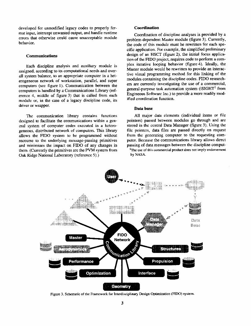
Each discipline analysis and auxiliary module is
assigned, according to its computational needs and over-
all system balance, to an appropriate computer in a bet-
erogeneous network of workstation, parallel, and super
computers (see figure 1). Communication between the
computers is handled by a Communications Library (ref-
erence 4, middle of figure 3) that is called from eachmodule or, in the case of a legacy discipline code, its
driver or wrapper.
The communication library contains functions
designed to facilitate the communications within a gen-eral system of computer codes executed in a hetero-
geneous, distributed network of computers. This libraryallows the FIDO system to be programmed without
recourse to the underlying message-passing primitives
and minimizes the impact on FIDO of any changes in
them. (Currently the primitives are the PVM system from
Oak Ridge National Laboratory (reference 5).)
Coordination
Coordination of discipline analyses is provided by a
problem-dependent Master module (figure 3). Currently,the code of this module must be rewritten for each spe-
cific application. For example, the simplified preliminary
design of an HSCT (figure 2), the initial focus applica-
tion of the FIDO project, requires code to perform a com-
plex iterative looping behavior (figure 4). Ideally, theMaster module would be rewritten to provide an interac-
tive visual programming method for this linking of the
modules containing the discipline codes. FIDO research-
ers are currently investigating the use of a commercial,general-purpose task automation system (iSIGHT 1 from
Engineous Software Inc.) to provide a more readily mod-ified coordination function.
Data base
All major data elements (individual items or file
pointers) passed between modules go through and are
stored in the central Data Manager (figure 3). Using the
file pointers, data files are passed directly on request
from the generating computer to the requesting com-
puter. Because the communications library allows direct
passing of data messages between the discipline comput-IThe use of this commercial product does not imply endorsement
by NASA.
Figure 3. Schematic of the Framework for Interdisciplinary Design Optimization (FIDO) system.
3

! !
_---_= Program
Q = Data
Rigd Aero Weinhts I v _.)u"'"='Y"LJ ...., Analysis _ _ _ upumlzer
I A_'E2_ _ Aeroelastic I .r
SOC = Start of Cruise _, ,_,.,,, _.L_ _D_, _ ...... _ _ .... L, _.aD_'
--T-
SOC _ EOC
Prop Analysis Prop Analysis
[ Peff°rmance I "_@
Figure 4. FIDO discipline interaction diagram for an HSCT application.
Aero Grid i FEM NodeUpdate Update
ers, direct communications of messages can be imple-
mented if the increased efficiency warrants it.
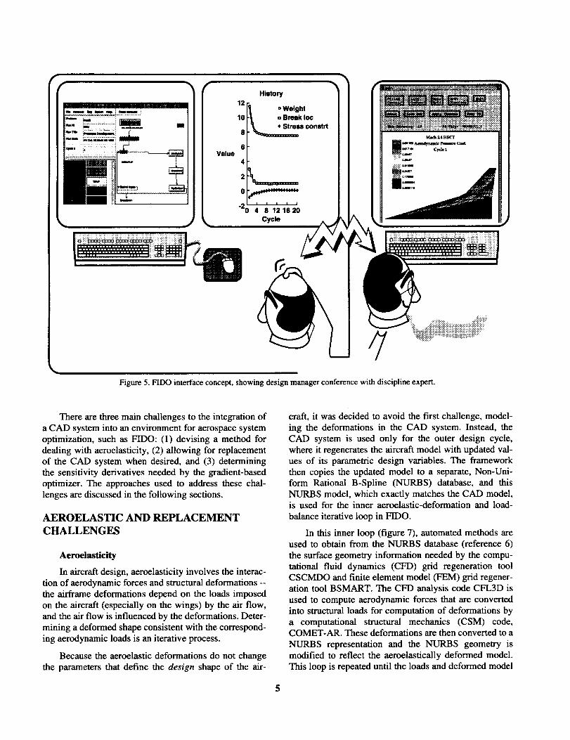
User interface
The FIDO Graphical User Interface (GUI) gives the
design manager control of the process and provides a
way to view optimization progress and intermediateresults. A feature of FIDO is that the viewing module
(Spy in figure 3) can be invoked in multiple instancesand from remote sites on the network in order to allow
remote experts to evaluate the design graphically while it
is in progress (figure 5).
Configuration files
Before execution of each case, the design manager
typically invokes the GU]'s Setup module to pick the
system configuration and the initial conditions and con-
straints of the optimization process from a range of previ-
ously defined possibilities. These are contained in four
configuration files that define the data in standardizedformats: a file of the characteristics of all host machines
to be considered; a file pairing the computational mod-
ules with the machines to be used for execution of a par-
ticular case; a file defining the base aircraft geometry,
flight conditions, and design variable initial and bound-
ing values; and a file specifying which segments are to be
run in a debug or demonstration mode.
Upgrades
Current plans are to upgrade the FIDO system to use
more realistic analysis modules, including both high-
fidelity structure (adaptive refinement finite-elementmethod) and aerodynamic (Navier-Stokes CFD) codes.
A commercial computer aided design (CAD) system
(Pro/ENGINEER ® from Parametric Technology Corpo-ration 2) will be used to provide these codes with a uni-
fied, high-fidelity surface description. Because the
purpose of the FIDO framework is to automate the MDO
process, the CAD system must regenerate a new surface
model each time the value of any geometric design vari-
able is changed (as in figure 6).
2The use of this commercial product does not imply endorsementbyNASA.
4
Value
History
12o Weight
10 ._ a Break Ioc
. _mu constrt8
6
4
2 _ ................
"%; ; 1;1;20Cycle
Figure 5. FIDO interface concept, showing design manager conference with discipline expert.
There are three main challenges to the integration of
a CAD system into an environment for aerospace system
optimization, such as FIDO: (1) devising a method for
dealing with aeroelasticity, (2) allowing for replacementof the CAD system when desired, and (3) determining
the sensitivity derivatives needed by the gradient-based
optimizer. The approaches used to address these chal-
lenges are discussed in the following sections.
AEROELASTIC AND REPLACEMENT
CHALLENGES
Aeroelasticity
In aircraft design, aeroelasticity involves the interac-
tion of aerodynamic forces and structural deformations --
the airframe deformations depend on the loads imposed
on the aircraft (especially on the wings) by the air flow,
and the air flow is influenced by the deformations. Deter-
mining a deformed shape consistent with the correspond-
ing aerodynamic loads is an iterative process.
Because the aeroelastic deformations do not changethe parameters that define the design shape of the air-
craft, it was decided to avoid the first challenge, model-
ing the deformations in the CAD system. Instead, the
CAD system is used only for the outer design cycle,
where it regenerates the aircraft model with updated val-
ues of its parametric design variables. The framework
then copies the updated model to a separate, Non-Uni-form Rational B-Spline (NURBS) database, and this
NURBS model, which exactly matches the CAD model,is used for the inner aeroelastic-deformation and load-
balance iterative loop in FIDO.
In this inner loop (figure 7), automated methods areused to obtain from the NURBS database (reference 6)
the surface geometry information needed by the compu-
tational fluid dynamics (CFD) grid regeneration toolCSCMDO and finite element model (FEM) grid regener-
ation tool BSMART. The CFD analysis code CFL3D is
used to compute aerodynamic forces that are converted
into structural loads for computation of deformations by
a computational structural mechanics (CSM) code,COMET-AR. These deformations are then converted to a
NURBS representation and the NURBS geometry is
modified to reflect the aeroelastically deformed model.
This loop is repeated until the loads and deformed model
5

Figure 6. Parametric change of leading-edge sweep in Pro/ENGINEER model of an HSCT.
shape converge, usually in three to five iterations. Then,
the CFD and CSM results are applied to the overall opti-
mization process, along with other discipline results, to
determine a new set of values for the design variables
(CAD parameters). These new values are used to regen-
erate the CAD model, and the whole process repeats untilno further improvement in the objective is evident.
CAD replacement
It has become apparent that no one CAD system isuniquely applicable to MDO frameworks. Because most
CAD systems can export the required NURBS geometry,the uncoupling of the CAD and aeroelastic databases as
described above also eases the second challenge, because
it simplifies the replacement of the CAD system whenthis is desired
SENSITIVITY DERIVATIVES
CHALLENGE
The third major challenge to integration of the CAD
system into FIDO is the determination of the sensitivityderivatives used by the gradient-based optimizer. Essen-
tially, what is needed is the partial derivative of each
computational grid point position with respect to each
geometric design variable. These geometric derivatives
can be chained together with derivatives in the discipline
codes with respect to the grid points to obtain, eventu-ally, sensitivities of constraints and objective functions
with respect to the design variables. An example is the
derivative of total aircraft weight with respect to wingleading-edge sweep angle, including contributions from
the aerodynamic loads and the structural deformations.
The optimizer then applies the overall derivatives to its
algorithm for determining improved values of the designvariables.
Derivatives using NURBS database
In some instances it will be possible to relate the
NURBS control points to the design variables. For thosedesign variables, the required derivatives can be com-
puted without recourse to the CAD system. But, some
alternate means will have to be found to compute thederivatives of design variables that cannot be so related.
Finite difference approximations
The usual direct approach is to apply an incrementalchange to each geometric design variable in turn and
compute its finite difference approximations for the
required derivatives. This method is being used by the

Des ie°metric-" r fS uc algn Variables_/---_.--___/ CAD System
(Pro�ENGINEER) _gn Varia_J[
_ _CFDGrid / _ [CSMGrid] _.--__
/" CFD "_ IGenerat°r _N/__.._[Generator ["_'fFEM_"k
\ -_ ....... .......
[Computational] , f • _ , [ Computational "
/Fluid Dynamics / [ Loads / Deformations / IStructural Mechanics| (CFD) Analysis ] [Interface J Interface J [ (CSM)Analysis
Figure 7. Aemelastic iteration loop (heavy arrows) in the FIIX) system.
FIDO project in the interim while pursuing analyticderivative methods.
The problem with finite differences is that the
approximated value of a derivative sometimes is very
sensitive to the size of the design variable increment used
to compute it. The mathematical basis for the approxima-tion is the Mean Value Theorem of calculus, which
assumes that the function being approximated is continu-
ous. This assumption is not strictly true for any computed
function (due to round off and truncation errors) and may
be far off (relatively speaking), depending on the nature
of the geometry at a particular point. Even a relatively
smooth surface geometry has regions of low and high
sensitivity to any given design variable. Thus, the bestsize for the increment to use for each design variable
depends on the derivative being computed; differentincrements may well be appropriate for different deriva-tives.
Obviously, trade-offs are involved in computing the
finite difference approximations. If a single increment ischosen, the resulting poor approximation of derivatives
can lead to poor performance of the optimizer. On theother hand, if many different increments are used for
each design variable, the overall system performance
may be poor because of the many additional regenera-
tions required of the CAD system. These trade-offs andother issues relating to the use of finite difference
approximations of geometric sensitivity derivatives arebeing studied at the Langley Research Center as the inte-
gration of Pro/ENGINEER with FIDO proceeds.
Analytic derivatives
Ideally, one would like to have analytically definedsensitivity derivatives for use in gradient-based optimiza-
tion. Because surfaces in the CAD system are defined by
a patchwork of analytic curves and surfaces, it is possible
to produce analytic derivatives of those curves and sur-
faces. And, because the CAD system contains within its
code the logic and equations that relate the surface
patches to the design variables (CAD parameters), it is
theoretically possible to produce analytic derivatives rel-ative to the design variables.
A computer code, ADI-C (for Automatic Differenti-ation of C), which has been developed by researchers at
Rice University and Argonne National Laboratory, takes
a normal C code as its input and produces as output the
same code supplemented with additional statements to
compute the analytic derivatives of selected variables

withrespectedtoselectedinputvariables. ADI-C (and itsFortran forerunner ADIFOR (reference 7)) have been
tested and found to work reliably on such complex soft-ware as block-gridded CFD codes (reference 8)
Of course, the application of ADI-C requires accessto the source code. Because the CAD system source code
is proprietary, some kind of cooperative arrangementmust be made with its owners in order for ADI-C to be
applied. In preliminary talks, sales representatives have
shown some interest relating to the application of ADI-C
to the Pro/ENGINEER CAD system. It would appear to
be a great advantage for a CAD system to be able to sup-ply sensitivity derivatives to its users. However, it will
ultimately take a business decision by a CAD system
vendor to devote the necessary resources before this ave-nue to integrating a CAD system with MDO can be fol-lowed.
Transformation matrix formulation
There is another approach to obtaining analytic sen-
sitivity derivatives that uses presently available informa-
tion. The geometric sensitivity derivatives are essentially
the linear transformation matrices used in producing the
graphical displays of the geometry. Or, at least, the trans-formation matrices contain all the information needed to
compute the derivatives, as in the case of rotations. ForPro/ENGINEER these transformation matrices can be
accessed through a system library known as Pro/DEVELOP. Thus, the information needed is available
without differentiating throughout the Pro/ENGINEER
source code. At NASA Langley, we are currently lookinginto how to write the code necessary to pull out all the
required matrices from the Pro/ENGINEER database and
put them into sensitivity derivative form.
CONCLUDING REMARKS
More and more, the design of complex engineeringproducts, such as aircraft, is coming to rely on computer-
aided design systems. And, more and more, optimization
methods are being applied to the design of complex engi-
neering products in an effort to make them more efficientto manufacture, maintain, and use. Thus, there is a natu-
ral need to integrate computer-aided design systems withthe emerging optimization environments, such as FIDO
(the Framework for Interdisciplinary Design Optimiza-
tion described herein). This report has discussed three
issues arising in the integration and how they are being
handled by the FIDO project. Of these, decoupling seemsto handle the aeroelastic issue well and eases the CAD
replacement, but the issue of deriving geometric sensitiv-
ity derivatives from the CAD system is more problemati-cal. Which of the four proposed solutions (NURBS
database, finite differences, CAD analytical derivatives,or transformation matrix analytical derivatives) turns out
to be most effective in the long run remains to be seen.
REFERENCES
1. Townsend, J.C.; Weston, R.P., and Eidson, T.M.: A Program-wing Environment for Distributed Complex Computing. AnOverview of the Framework for Interdisciplinary Design Opti-mization (FIDO) Project. NASA TM 109058, December 1993.
2. Weston, R.E; Townsend, J.C.; Eidson, T.M.; and Gates, R.L.:
A Distributed Computing Environment for MultidiseiplinaryDesign. 5th AIAA/USAF/NASA/ISSMO Symposium onMultidiseiplinary Analysis and Optimization, Panama City,FL, 1994. (Published in AIAA CP9413, pp. 1091-1097; alsoavailable at NASA Langley Technical Report Server URLhttp://techreports.larc.nasa.gov/ltrs/1994.html)
3. Weston, Robert P.: FIDO - Framework for InterdisciplinaryDesign Optimization, A Programming Environment for Dis-tributed Complex Computing. WWW URL http://hpccp-www.larc.nasa.gov/~fido/homepage.html, 1996.
4. Eidson, T.M.: A Programming Support Library for DistributedMemory Architectures. High Technology Report No. HTC-9501, High Technology Corporation, Hampton, VA, March1995
5. Breshears, C.: PVM Guide. Joint Institute for ComputationalScience, University of Tennessee. (Available on the WWW atURL http://csep I .phy.ornl.gov/CSEP/PVM/PVM.html).
6. Samareh, Jamshid A.: Use OF CAD Geometry in MDO. 6thAIAA/USAF/NASA/ISSMO Symposium on Multidisci-plinary Analysis and Optimization, Bellevue, WA, AIAA-96-3991, September, 1996, p. 12ff (Available at NASA LangleyTechnical Report Server URL http://techreports.larc.nasa.gov/ltrs/1996-cit.html)
7. Bischof, Christian; Carle, Alan; Khademi, Peyvand; andManer, Andrew: The ADIFOR 2.0 System for the AutomaticDifferentiation of Fortran 77 Programs. CRPC-TR94491 or
ANL/MCS-P481-1194, 1994. (See also WWW URL http://www.cs.rice.edu/~adifor/').
8. Taylor NI, A.C., Oloso, A., and Newman III, J.C.,"CFL3D.ADII (Version 2.0): An Efficient, Accurate, General-Purpose Code for Flow Shape-Sensitivity Analysis," Proc.,15th AIAA Applied Aero. Conf., AIAA Paper 97-2204, June1997.
8


Form ApprovedREPORT DOCUMENTATION PAGE o_e No.orzo_o_ee
Publicrel0o(llngburden/or this collectionof tm_ormationis estimatedto average1hourper response,includingthe time forreviewing instructions,searchingexistingdata sourcesgatheringend maintainingthe data needed,andcompletingand reviewingthe collectionof information.Send commentsregardingthis 10urdenestimateor anyother aspectof thi|collectionof information,includingsuggestionslot reducingthis burden,to WashingtonHeadquartersSen/¢es, Dkectoratefor Info¢mattonOperationsand Reports,1215Jeffarsu_DavisHlgh_y, Suite 1204, Arlington,VA22202J,.302,and tothe Officeof Managementand Budget,PaperworkReductionProject(0704-0188),Washington,DC 20503.
1. AGENCY USE ONLY (Leave blank) 2. REPORT DATE
May 19984. TITLE AND StJtJi,, -E
Integration of a CAD System Into an MDO Framework
3. REPORT TYPE AND DATES COVEREDTechnical Memorandum
6. AUTHOR(S)
Townsend, J. C., Samareh, J. A., Weston, R. P., and Zorumski, W. E.
7. PERFORM:_JG ORGANIZATION NAME(S) AND ADDRESS(ES)
NASA Langley Research Center
Hampton, VA 23681-2199
9. SPONSORING/MONITORING AGENCY NAME(S) AND ADDRESS(ES)
National Aeronautics and Space Administration
Washington, DC 20546-0001
11. SUPPLEMENTARY NO i ,-_
5. FUNDING NUMBERS
509-10-11-01
8. PERFORMING ORGANIZATIONREPORT NUMBER
L-17726
10. SPONSORING/MONITORINGAGENCY REPORT NUMBER
NASA/TM-1998-207672
Townsend, Weston, and Zorumski: Langley Research Center, Hampton, VA; Samareh: Computer Sciences Corpo-ration, Hampton, VA. Based on presentation to Engineering Foundation conference on Optimization in Industry,March 23-27, 1997, in Palm Coast, FL
1211. bi_iMIBUTION/AVAILABILITY STATEMENT
Unclassified-Unlimited
Subject Category 02 Distribution: NonstandardAvailability: NASA CASI (301) 621-0390
12b. DISTRIBUTION CODE
13. AiS mHACT (Maximum 200 words)
NASA Langley has developed a heterogeneous distributed computing environment, called the Framework for Inter-
disciplinary Design Optimization, or FIDO. Its purpose has been to demonstrate framework technical feasibility'and usefulness for optimizing the preliminary design of complex systems and to provide a working environment fortesting optimization schemes. Its initial implementation has been for a simplified model of preliminary design of ahigh-speed civil transport. Upgrades being considered for the FIDO system include a more complete geometrydescription, required by high-fidelity aerodynamics and structures codes and based on a commercial ComputerAided Design (CAD) system. This report presents the philosophy behind some of the decisions that have shapedthe FIDO system and gives a brief case study of the problems and successes encountered in integrating a CAD sys-tem into the FIDO framework.
14. SUBJECT TERMS
multidisciplinary optimization frameworkscomputer-aided design
17. SECURITY CLASSIFICATION lB. SECURFi-Y CLASSIFICATIONOF REPORT OF THIS PAGE
Unclassified Unclassified
NSN 7540-01-280-5500
19. SECURITY CLASSIRCATIONOF ABSTRACT
Unclassified
15. NUMBER OF PAGES
1316. PRICE CODE
A03
20. UMITATIONOF ABSTRACT
Standard Form 298 (Ray. 2-89)Prescribedby ANSI Std,Z39-1B298-102