Integration and Test of the ATLAS Central Solenoid
23
ATLAS project Integration and Test of the ATLAS Central Solenoid Roger Ruber for the ATLAS CS team, LAr Meeting, CERN, 26-27 January 2004
Transcript of Integration and Test of the ATLAS Central Solenoid

ATLASproject
Integration and Testof the
ATLAS Central Solenoid
Roger Ruberfor the ATLAS CS team,
LAr Meeting, CERN, 26-27 January 2004

2
Contents1. Introduction2. Progress Report3. On-surface Integration4. On-surface Test5. Conclusions

3
Introduction

4
Solenoid LayoutThin superconducting central solenoid:
Bc = 2T (I = 7600A)
5.3m × φ2.3m × 45mm
wall thickness = 0.66 X0
E/M = 7.1 kJ/kg
C
B
A
valve unit
coilSystem consists of:A. thin solenoid coilB. chimneyC. control dewar +
proximity cryogenics

5
Factory Test in Japan
Solenoid Coil + Test Cryostatmain IWV, temp. OWV
Control Dewar
Chimney
spoolbox

6
Progress Report2001:• delivery components2002-2003:• proximity cryogenics• chimney• power supply• cryogenics control• surveyIn progress:• magnet control system• magnet safety system• solenoid integration

7
Chimney Test Results
• excitation up to 9 kA• verified safety of the design:
– mass flow stop to SQD trip:28min. until quench
• proximity cryogenics and control– dynamic heat balance:
heater up to 70W(cooling line) +3W(LHe level)– 150m capillary for (differential) pressure transducers

8
Survey October 2003
potentiometer
GFRP rod
Coi
l end
ring
Z
Y

9
Survey Results• coil with respect to IWV
– vertical offset -1.6 to –2.6 mm– axial centre of the winding
• warm: at -13.1mm• cold: at -0.1mm (4K, 2T)
– error bars in order of 0.3 to 0.5 mm
• observed permanent axial shrinkage is– 1.6mm (potentiometer) - 1.8mm (optical survey)
• circularity solenoid end flanges– end A: +/- 2.7mm ; end C: +/-1.3mm

10
On-surface Integration
Additional chimney for test
May 2002
August 2003

11
Mechanical Integration
Insertion
January 2004
Coil

12
Services Integration
Joint SC cable + cryo line
Joint cryo line
Conductor: 4 cables, main + side, supply & returnCryogenics: 4 tubes, 4.5K + 80K, supply & return

13
Integration Work
Barrel CryostatEnd A
Chimney

14
On-surface Test
Solenoid Coil + Barrel Cryostat
Control Dewar
Chimney Valve Unit
Bus-bars

15
Test Objectives
• confirm operation– run at nominal current + 5% (8kA)– safety for quench
• study interaction with detector– influence of magnetic field and eddy currents– thermal shielding of warm coil & bulkhead
• test final control and safety systems– including interlock with detector

16
Test ScheduleWeek
1 2 3 4 5 6 7 8 9 10 11 12 13 14 15 16 17 18 19 20cool down filling test warm up
detector
test warm upmagnet
• cool down magnet (1 – 2 weeks)– in parallel with detector
• magnet test (2 weeks)– confirm operation in parallel with LAr filling– interaction studies in begin phase detector test
• warm up of magnet– monitor temperature distribution with cold detector

17
Conclusions
• all components manufactured & tested• successful commissioned chimney and
proximity cryogenics• confirmed save chimney operation at 9kA
and in event of cryogenics’ failure• survey of CS+IWV completed• ready for full on-surface test by March

18
Acknowledgements
All my colleagues at• KEK:
for design and test• CERN and ATLAS:
for integration and on-surface test• Toshiba Co.:
for realization of the solenoid and welding machine

19
Back-up Slides

20
Factory Test Results
• maximum current 8.4kA (chimney: 10kA)• quench & cooling flow stop tests up to 7.6kA
21
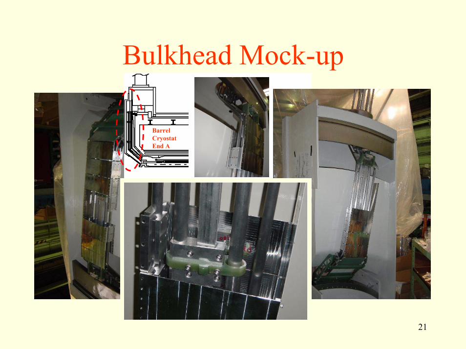
Bulkhead Mock-up
Barrel CryostatEnd A

22
Services Integration UX15
Field work:3 permanent joints
• 4 cooling tubes: 4.5K + 80K, supply & return(qualification ISO10042-B).
• 4 SC cables: main + side, supply & return
An orbital welding machine has been developed by Toshiba.
UX15
UX15
Bldg.180

23
Welding Scheme
insert
central insert, adjustable in length, edge of 30o
• pipe φ18mm (t=2mm); insert φ21 (t=3.5mm)• pipe φ24mm (t=3mm); insert φ27 (t=4.5mm)pipe is A6063; insert is A5083