
Integrating the Base of Aircraft Data (BADA) in CTAS ... · Integrating the Base of Aircraft Data...
50
NASA/TM–2012–216051 Integrating the Base of Aircraft Data (BADA) in CTAS Trajectory Synthesizer Michael Abramson University of California, Santa Cruz, California Kareem Ali University of California, Santa Cruz, California September 2012 https://ntrs.nasa.gov/search.jsp?R=20140007270 2018-08-29T16:25:44+00:00Z
-
Upload
duongduong -
Category
Documents
-
view
231 -
download
0
Transcript of Integrating the Base of Aircraft Data (BADA) in CTAS ... · Integrating the Base of Aircraft Data...

NASA/TM–2012–216051
Integrating the Base of Aircraft Data(BADA) in CTAS TrajectorySynthesizer
Michael AbramsonUniversity of California, Santa Cruz, California
Kareem AliUniversity of California, Santa Cruz, California
September 2012
https://ntrs.nasa.gov/search.jsp?R=20140007270 2018-08-29T16:25:44+00:00Z

NASA STI Program . . . in Profile
Since its founding, NASA has been dedicatedto the advancement of aeronautics and spacescience. The NASA scientific and technicalinformation (STI) program plays a key partin helping NASA maintain this importantrole.
The NASA STI Program operates under theauspices of the Agency Chief InformationOfficer. It collects, organizes, provides forarchiving, and disseminates NASA’s STI.The NASA STI Program provides access tothe NASA Aeronautics and Space Databaseand its public interface, the NASA TechnicalReport Server, thus providing one of thelargest collection of aeronautical and spacescience STI in the world. Results arepublished in both non-NASA channels andby NASA in the NASA STI Report Series,which includes the following report types:
• TECHNICAL PUBLICATION. Reports ofcompleted research or a major significantphase of research that present the resultsof NASA programs and include extensivedata or theoretical analysis. Includescompilations of significant scientific andtechnical data and information deemed tobe of continuing reference value. NASAcounterpart of peer-reviewed formalprofessional papers, but having lessstringent limitations on manuscript lengthand extent of graphic presentations.
• TECHNICAL MEMORANDUM.Scientific and technical findings that arepreliminary or of specialized interest, e.g.,quick release reports, working papers, andbibliographies that contain minimalannotation. Does not contain extensiveanalysis.
• CONTRACTOR REPORT. Scientific andtechnical findings by NASA-sponsoredcontractors and grantees.
• CONFERENCE PUBLICATION.Collected papers from scientific andtechnical conferences, symposia, seminars,or other meetings sponsored orco-sponsored by NASA.
• SPECIAL PUBLICATION. Scientific,technical, or historical information fromNASA programs, projects, and missions,often concerned with subjects havingsubstantial public interest.
• TECHNICAL TRANSLATION. English-language translations of foreign scientificand technical material pertinent toNASA’s mission.
Specialized services also include creatingcustom thesauri, building customizeddatabases, and organizing and publishingresearch results.
For more information about the NASA STIProgram, see the following:
• Access the NASA STI program home pageat http://www.sti.nasa.gov
• E-mail your question via the Internet [email protected]
• Fax your question to the NASA STI HelpDesk at 443-757-5803
• Phone the NASA STI Help Desk at443-757-5802
• Write to:NASA STI Help DeskNASA Center for AeroSpace Information7115 Standard DriveHanover, MD 21076–1320
NASA/TM–2012–216051
Integrating the Base of Aircraft Data(BADA) in CTAS TrajectorySynthesizer
Michael AbramsonUniversity of California, Santa Cruz, California
Kareem AliUniversity of California, Santa Cruz, California
National Aeronautics andSpace Administration
Ames Research CenterMoffett Field, California 94035-1000
September 2012

The use of trademarks or names of manufacturers in this report is for accurate reporting and does notconstitute an offical endorsement, either expressed or implied, of such products or manufacturers by theNational Aeronautics and Space Administration.
Available from:
NASA Center for AeroSpace Information7115 Standard Drive
Hanover, MD 21076-1320443-757-5802

Abstract
The Center-Terminal Radar Approach Control (TRACON) Automation System (CTAS), developedat NASA Ames Research Center for assisting controllers in the management and control of air trafficin the extended terminal area, supports the modeling of more than four hundred aircraft types.However, 90% of them are supported indirectly by mapping them to one of a relatively few aircrafttypes for which CTAS has detailed drag and engine thrust models. On the other hand, the Base ofAircraft Data (BADA), developed and maintained by Eurocontrol, supports more than 300 aircrafttypes, about one third of which are directly supported, i.e. they have validated performance data.All these data were made available for CTAS by integrating BADA version 3.8 into CTAS TrajectorySynthesizer (TS). Several validation tools were developed and used to validate the integrated codeand to evaluate the accuracy of trajectory predictions generated using CTAS “native” and BADAAircraft Performance Models (APM) comparing them with radar track data. Results of thesecomparisons indicate that the two models have different strengths and weaknesses. The BADAAPM can improve the accuracy of CTAS predictions at least for some aircraft types, especiallysmall aircraft, and for some flight phases, especially climb.
LIST OF ACRONYMS
A306 Airbus A300B4-600APM Aircraft Performance ModelARTCC Air Route Traffic Control CenterATR72 Alenia ATR-72B190 Beechcraft 1900B733 Boeing 737-300B737 Boeing 737-700B738 Boeing 737-800B752 Boeing 757-200BADA Base of Aircraft DAtaBADA TS CTAS TS using any elements of BADA APMBE20 Beechcraft Super King Air 200BE36 Beechcraft Bonanza Model 36BE40 Beechjet 400/T-1 JayhawkBE9L Beechcraft King Air 90C182 Cessna 182 SkylaneC560 Cessna Citation VC56X Cessna Citation Excel/560XLC750 Cessna Citation XCAS Calibrated Air SpeedCRJ2 Canadair Regional Jet CRJ-200CRJ7 Canadair Regional Jet CRJ-700CRJ9 Canadair Regional Jet CRJ-900CTAS Center-TRACON Automation SystemCTAS/BADA TS CTAS TS with support for BADA APMCTAS TS CTAS Trajectory Synthesizer with CTAS APM
1

E120 Embraer EMB 120 BrasiliaE135 Embraer ERJ-135E145 Embraer ERJ-145E170 Embraer E-170ETA Estimated Time of ArrivalH25B Raytheon BAe-125-700/800HCS Host Computer SystemIBST Interval-Based Sampling TechniqueLJ35 Learjet 35MD82 McDonnell Douglas MD-82MD83 McDonnell Douglas MD-83PC12 Pilatus PC-12 SpectrePTD Performance Table DataROCD Rate of Climb or DescentRUC Rapid Update CycleSA Separation AssuranceSR22 Cirrus SR-22TAS True Air SpeedTOC Top of ClimbTOD Top of DescentTRACON Terminal Radar Approach ControlTS Trajectory SynthesizerZDV Denver Air Route Traffic Control Center (ARTCC)ZFW Fort Worth ARTCCZLA Los Angeles ARTCC
1 Introduction
The Center-Terminal Radar Approach Control (TRACON) Automation System (CTAS) is a setof tools developed to help air traffic controllers manage complex air traffic flows to reduce delaysand increase safety [1]. These tools, known also as CTAS client applications, rely on the TrajectorySynthesizer (TS) [3,4] as the core computational engine for generating accurate predictions of 4D-trajectories using the detailed aircraft performance characteristics, weather data, and data from theHost Computer System (HCS). TS outputs predicted aircraft position, altitude, and performanceparameters, such as drag, thrust, weight, Rate of Climb or Descent (ROCD), and fuel consumption,as a function of time.
CTAS currently supports more than four hundred aircraft types, but about 90% of them aresupported indirectly by mapping to aircraft types with known drag and engine thrust models.Obtaining the detailed performance data for more aircraft types from manufacturers and validatingthem may be problematic and time-consuming. Besides that, previous research validating theaccuracy of CTAS TS (see [5] and [6]) was limited to certain centers and aircraft types, and theoverall accuracy of CTAS predictions remained largely unknown.
On the other hand, the Base of Aircraft DATA (BADA) supports more than 300 aircraft types,including about a hundred aircraft types with extensively validated performance data. BADA is an
2

Aircraft Performance Model (APM) developed and maintained by Eurocontrol and available freeof charge. This model is documented in the BADA User Manual [7]. The complementary “Base ofAircraft DATA (BADA) Aircraft Performance Modelling Report” [8] provides further definition ofBADA parameters.
Note that BADA documentation [7] does not always make a clear distinction between the physi-cal and operational components. For instance, BADA thrust model blends together the physicalparameters, such as maximum engine thrust, and operational considerations like the flight config-uration or using reduced climb power. Note also that BADA does not include any official softwareimplementation, but it provides the data that can be used to verify correctness of any software thatimplements the BADA APM.
The main potential advantage of using BADA is that it directly supports more aircraft types incomparison with CTAS and may provide more accurate aircraft parameters for some aircraft typescurrently supported by CTAS. Besides that, some elements of the BADA operational model, suchas default speeds and the use of reduced climb power, may be based on more realistic assumptions.Another important benefit of using BADA is that it is maintained by Eurocontrol and it is expectedto be regularly updated and improved over time.
To take full advantage of these benefits, BADA APM was integrated in CTAS TS to augment the“native” CTAS APM for aircraft types not supported by CTAS or having the better models inBADA. A set of validation tools was developed and used to judge the accuracy of BADA APM andCTAS APM by comparing trajectory predictions built using both performance models to radartrack and other reference data.
Software design for BADA-CTAS Integration is presented in Section 2 of this TM. Section 3 de-scribes the tools developed to validate the correctness of software implementation and the accuracyof BADA APM in comparison with CTAS APM. Section 4 briefly describes the results of softwarevalidation. Section 5 describes the results of evaluation of CTAS TS with “native” CTAS andintegrated BADA model for various aircraft types and operational parameters. The TM is con-cluded with Section 6, summarizing the main findings. The Appendix includes examples of BADAOperation Performance Files (OPF) and Performance Table Data (PTD) files.
2 BADA-CTAS Integration
CTAS TS with support for BADA will be referenced in this TM as “CTAS/BADA TS”. The term“CTAS TS” will refer to CTAS/BADA TS using only “native” CTAS APM, which is functionallyequivalent to the “original” CTAS TS without support for BADA APM.
CTAS TS is a faster-than-real-time trajectory predictor that can be called for every radar trackhit, or every 12 seconds, for each of thousands flights managed by CTAS tools. So, the main designrequirement was to minimize performance penalty introduced by adding support for both CTASand BADA models. Also, it was desirable to minimize CTAS TS code changes, to separate clearlythe BADA-specific code from the rest of CTAS TS, and to make new code consistent with existingCTAS TS infrastructure.
These requirements motivated the design of container class APMDef, encapsulating CTAS and
3

BADA APMs in abstract model definition interfaces, such as ADragDef, AThrustDef, etc., asshown in Figure 1. Here “[CTAS TS]” denotes any classes of “original” CTAS TS reused inCTAS/BADA TS code. In particular, VSFixed is the base CTAS TS class for all vertical solutionclasses, and DragModel and ThrustModel are the existing CTAS TS classes modeling drag andengine thrust. Each model definition interface member variable in APMDef class, such as mDragDefand mThrustDef, is instantiated only once to CTAS or BADA implementation in constructors ofcorresponding Model Definition subclasses for each aircraft type based on BADA configurationfiles. Hence, extending CTAS TS for BADA APM does not introduce any performance penalty inrun time.
Figure 1. CTAS/BADA TS Class Diagram
Our implementation of CTAS/BADA TS fully supports BADA APM with additional features andextensions listed below:
4
• Easy switch between CTAS “native” and BADA APM by changes in user-defined configura-tion files;
• BADA can be used for specific aircraft types or for all aircraft types;• Each element of BADA APM (drag model, thrust model, speed profile, etc.) can be turned
on/off and tested separately;• Some parameters of BADA APM, such as aircraft weight, can be specified as aircraft-specific
user-defined values;• The weight of aircraft can be specified as a constant or variable. In the latter case, the weight
is calculated as a function of time based on fuel consumption as described in [9];• BADA thrust model was extended to allow the variable power settings to control the engine
thrust in response on client speed requests, such as speed advisories for trial planning. Specif-ically, the maximum climb power is used for acceleration, and the BADA idle-thrust is usedfor deceleration in any flight phase;
• Fuel consumption is always based on instantaneous thrust value, even if it deviates fromnominal BADA thrust due to client requests;
• Speed profile can be defined as CTAS, BADA “exact” with nominal BADA speeds definedin [7], and BADA “hybrid” with BADA speeds that can be updated by speed requests fromCTAS client applications;
• Some BADA options defined as “global” in [7], such as reduced climb power or expediteddescent, can be defined as aircraft-specific in CTAS/BADA TS.
This rich functionality is controlled by two BADA-CTAS Configuration Files, loaded by CTAS atstartup time:
• data sources, which specifies the available data sources (currently CTAS and BADA 3.8, butother versions of BADA can be added later);
• aircraft data sources, which defines the additional options for each element (sub-model) ofAPM.
If BADA APM is requested, the following BADA Input Files will be used (see [7] for details):
• SYNONYM.NEW: the ICAO codes and prefixes for files with aircraft-specific data;• BADA.GPF - Global Parameters Files, containing the values for BADA global parameters;• OPF files - Operation Performance Files (one file for each aircraft type, see Appendix A);• APF files - Airline Procedures Files (one file for each aircraft type).
Typical operation of CTAS/BADA TS includes three steps:
1. Read BADA-CTAS configuration files;2. Read CTAS common aircraft data files and BADA data files, and use the data from configu-
ration files to instantiate CTAS or BADA implementations for each APM element;3. Generate trajectories using CTAS and/or BADA APM as defined in configuration files.
The trajectories generated by CTAS/BADA TS may be saved in archive files for further analysisand comparisons with radar track and other benchmark data using validation tools described innext section.
5

3 Validation Tools and Methods
The goals of validation are two-fold. First of all, it should be confirmed that implementation ofBADA APM in CTAS/BADA TS is correct by comparison with benchmark data, provided byEurocontrol in the form of “Performance Table Data” (PTD) files (see [7] and Appendix B). Next,it should be examined how the usage of BADA APM will help improve CTAS. This second goalcan be accomplished by running CTAS/BADA TS with CTAS APM and BADA APM side by sideand comparing their predictions to each other and to radar track data.
For a first goal, the PTD validation tool was developed to validate the implementation of BADAAPM by reporting how closely the results produced by the current version of CTAS/BADA TSmatch the reference data from PTD files. For these comparisons linear interpolation on the TSoutput is used to get data at flight levels, specified in BADA PTD files.
For a second goal, namely, validation of CTAS APM and BADA APM, a number of other toolswas created. Two of them are briefly considered in this section:
1. TrackComparer tool2. CmSimTrackComparer tool
TrackComparer tool uses methodology similar to what was described in [6]. It combines threedifferent analysis techniques:
• Systematic analysis - Comparison of every predicted position with actual track data, and ofpredictions against each other, provided that data can be compared for a specified minimumtime or path distance. This analysis generates systematic error statistics for all aircraft types,but it does not reflect the evolution of error along track.
• Interval-based sampling technique (IBST) - Samples track data and predictions atregular intervals along the track, as described in [10].
• Separation assurance trajectory accuracy algorithm (SA analysis) - Computes met-rics at a specific lookahead time starting at (user-defined) climb and descending altitudes. SAanalysis is a truncated variant of IBST that computes metrics for only one (first) predictionfor each track. This makes it less computationally expensive than IBST, at the cost of areduced size of data set.
The tool requires the following inputs:
• Cm sim file, generated by CTAS using HCS data. It contains flight plans, flight plan amend-ments, and radar tracks.
• Trajectory archive files for trajectories generated by CTAS/BADA TS. These files are usedfor comparison with track data.
CmSimTrackComparer tool was originally developed for comparing CTAS/BADA TS predictionsagainst track data for idle-thrust descents with controlled cruise and descent speeds that wererecorded for Denver arrivals in 2009, studied in [11]. The tool can also be useful for other CTASdata analysis/validation tasks.
6

It combines the following functions:
• automatically generate requests to TS from radar track data;• invoke TS for each request;• compare generated predictions against tracks.
In contrast to TrackComparer, CmSimTrackComparer has only one required input, a cm sim file,that makes possible to run it without running CTAS. Optional input text files can be used to limitanalysis to particular flights and to specify estimated values for descent speeds and aircraft weights.
On the other hand, CmSimTrackComparer compares track data to predictions generated usingonly one APM, either CTAS or BADA, while TrackComparer can simultaneously compare CTASpredictions to track data, BADA predictions to track data, and BADA predictions to CTAS pre-dictions.
Both TrackComparer and CmSimTrackComparer tools use the metrics defined in [10]:
along-track error (time-correlated):
ΔAT t =�U · �V
‖�V ‖ (1)
along-track error (path-correlated):ΔAT p = tp − tt (2)
cross-track error (time-correlated):
ΔCT =‖�U × �V ‖
‖�V ‖ (3)
altitude error:Δh = ht − hp (4)
where t is a time, h is an altitude, and the subcripts p and t designate the path-based and time-based correlations. The vectors �U and �V are based on the position of aircraft denoted as AC anda trajectory segment between the points TJ1 and TJ2 as shown on Figure 2.
All metrics, except for the along-track error for the path distance correlation, have the characteristicthat the predicted trajectory is subtracted from the reference (or track). For BADA predictionscompared against CTAS, the reference is always the CTAS prediction.
Besides these metrics, TrackComparer calculates the metrics for “events,” such as the Top of Climb(TOC), the Top of Descent (TOD), and the Estimated Time of Arrival (ETA). In this study theTop of Climb is defined as the end of the longest procedural climb in the flight or prediction, and theTop of Descent is defined as the start of the longest procedural descent in the flight or prediction.A procedural climb is defined as a non-decreasing sequence of altitudes with at least one strictlyincreasing sequence of altitudes, and procedural descent as a non-increasing sequence of altitudeswith at least one strictly decreasing sequence of altitudes.
For arriving flights, CTAS makes a clear distinction between Center predictions originating in theARTCC and ending at the meterfix, and TRACON predictions within the TRACON. Consequently,the metrics for ETA are defined differently for these two classes of predictions. For a Center
7

Figure 2. Horizontal Trajectory Prediction Metrics
prediction, the ETA is the time when the track or prediction reaches the Center-TRACON boundary(the meterfix), while for a TRACON prediction the ETA is based on the end of trajectory.
For each comparison (e.g. for each prediction-reference pair) the maximum, minimum, mean, andabsolute mean errors are calculated and stored in SQL-lite database. Then the maximum, mean,minimum, and standard deviation are calculated over each of these metrics separately for CTAS vs.Track, BADA vs. Track, and BADA vs. CTAS comparisons. For example, the “mean of absolutemean errors” is the mean of absolute mean errors for all predictions. Other metrics used in thisTM are defined similarly.
4 CTAS/BADA TS Software Validation
Implementation of BADA APM in CTAS/BADA TS was validated using the PTD validation toolwith benchmark PTD files as of the 5th of May 2011. This validation was performed only forBADA “exact” speeds and constant weight, since the PTD files were generated for these conditions
The following two metrics were considered: a trajectory success rate, and a comparison successrate. The trajectory success rate is defined as a percentage of trajectories successfully generated byCTAS/BADA TS to all trajectory requests. CTAS/BADA TS may fail to generate trajectories forcertain requests because of unrealistic constraints or aircraft performance data or due to limitationsimposed by implementation of TS computational algorithms.
Over all considered aircraft types, e.g. all types for which the BADA provided the PTD files, thePTD validation gives 99.8% trajectory success rate.
The comparison success rate is defined as a percentage of successful comparisons to all comparisons.Comparison is considered successful if the mean absolute errors for all trajectory parameters areless than the specified tolerances listed in Table 1:
8

Table 1. PTD Comparison Tolerances
Parameter ToleranceTrue Air Speed (TAS) 5 knotsCalibrated Air Speed (CAS) 5 knotsMach 0.1Thrust 1000 NewtonsDrag 1000 NewtonsROCD 100 feet per minute
With these tolerances a comparison success rate with the PTD reference was 78.3%. The ma-jority of failed comparisons were due to thrust or ROCD. These failures occurred because “thePTF/PTD files do not take into account the flight envelope limitations”, as the BADA supportgroup acknowledged responding on request by the authors of this TM. Therefore, the tables inBADA PTD files include the data up to the maximum altitudes with a negative rate of climbindicating that aircraft cannot climb up to that altitudes. CTAS TS copes with this situation byincreasing thrust to achieve a minimum energy rate required for climb, while ROCD is calculatedfrom the Newton’s equation of motion and can never be negative in climb. Therefore, the BADAimplementation in CTAS/BADA TS disagrees with BADA PTD reference for conditions that arenot physically possible.
Increasing the thrust tolerance to 2000 Newtons and the ROCD tolerance to 200 feet per minuteresulted in an increased comparison success rate of 90.5%. All remaining failures were due to failedcomparisons in drag. All data in BADA PTD files are expressed on the coarse grid as functions ofthe flight level (FL) (see Appendix B). Hence, comparisons of CTAS/BADA TS results against thePTD data require interpolation between this coarse grid and the the grid used by CTAS/BADATS. The lift coefficient, and hence the drag, appear to be especially sensitive to these interpolationerrors. Other parameters, such as altitude and CAS, were not affected by these errors.
5 Evaluation of CTAS/BADA TS
BADA documentation [7] already allows certain variability in some elements of BADA APM. Forexample, a user can choose to use full or reduced climb power, standard descent or expedited descentwith spoilers, and so on. Implementation of BADA APM in CTAS/BADA TS further extends thisvariability. Hence, any discussion of CTAS/BADA TS evaluation results requires specification of“the variant” of BADA APM used.
First, the definitions of CTAS and BADA speed profiles should be considered. CTAS TS usesaircraft-specific default speeds, but they can be updated from client speed requests and the ini-tial speed from track. On another hand, BADA User Manual, [7], defines aircraft-specific speedsfor all flight phases, which will be called the “BADA exact” speed profile. In addition to this,CTAS/BADA TS supports the “BADA hybrid” speed profile, defined as BADA exact speeds, re-placed when necessary with speeds requested by CTAS clients. A variant of “BADA hybrid” speedprofile, which will be referred in this TM as “BADA hybrid hold,” holds initial speeds as CTAS TSdoes. Therefore, the “BADA hybrid hold” speed profile is similar to CTAS speed profile, except
9
the definition of default speeds: the BADA “exact” speeds from [7] are used as default speeds forBADA, while for CTAS the default speeds are explicitly specified for each aircraft type.
Next, the “default” initial aircraft weight should be defined, which is based on BADA referenceweight, corrected to account for a starting point of aircraft. CTAS TS does not have access toflight history before the first prediction point, so the method of initial weight correction based onestimated fuel burn, suggested in [12] and [13], could not be used. Therefore, a more practical,although less accurate, correction technique was necessary. This technique used heuristics, takinginto account a starting point of aircraft. Effectively, these heuristics ensured that the initial weightgradually approached the BADA maximum weight at the beginning of climb, and the “landingweight”, defined as BADA empty weight increased by 20%, at the end of descent. The code alsoensured that the actual aircraft weight could not fall below the “landing weight”.
BADA Base case can be defined as follows:
1. BADA thrust model;2. BADA drag model;3. BADA weight model that implies the weight starting from “default” initial weight and chang-
ing as a function of consumed fuel;4. Reduced climb power, which will give more realistic climb profile than the maximum thrust
does (see [7], p.24);5. BADA “exact” speed profile (requests are ignored);6. BADA model limits (trajectories assumed invalid if BADA limits are violated).
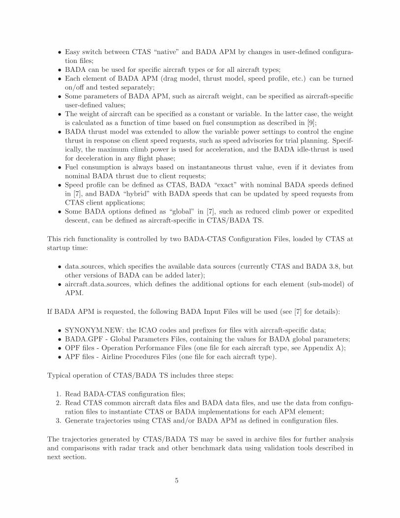
Therefore, the BADA Base case can be seen as the most “authentic” implementation of [7]. Allother BADA test cases are built upon the BADA Base case as shown in Table 2. Examining thesecases allows to study the effects of extensions of BADA APM and, to some degree, the effects ofuncertanties in speeds, weight, thrust, and drag.
Note that only the BADA Base case can be considered as a “nominal” case, for which the BADAAPM was validated by the Eurocontrol. All other cases are “off-nominal” models that requireadditional validation by comparisons of predicted trajectories against track data as described inthis section.
All comparisons were made using BADA version 3.8 and RUC weather files with 40km grid forcorresponding days and locations.
Table 2. BADA APM variants
CTAS speeds Base case, but CTAS speed profileHybrid Hold Base case, but BADA hybrid hold speed profileIncreased Weight Base case, but weight ratio = 110% (10% above “default” weight)Reduced Weight Base case, but weight ratio = 90% (10% below “default” weight)Maximum Climb Thrust Base case, but without reduced climb powerExpedited Descent Base case, but with expedited descentReduced Climb and Descent Maximum climb thrust, but with expedited descent
10

5.1 Fort Worth Center (ZFW), 3 days
The TrackComparer tool, briefly described in previous section, was used to compare radar trackdata with predictions obtained using CTAS/BADA TS for different BADA variants for 3 days oftraffic from Feb 23 to Feb 25 of 2011 in Fort Worth Center (ZFW).
Tables 3 and 4 summarize the performance of CTAS and various BADA variants for time-basedcorrelations. Each row in these tables includes the averaged (over all predictions) absolute valuesof maximal errors, mean errors, absolute values of mean errors, maximal errors, minimal errors,and standard deviations of metrics defined in Section 3.
As can be seen from Tables 3 and 4, all BADA variants perform as well or slightly better thanCTAS in terms of altitude and along-track errors. However, the differences between BADA andCTAS and between different BADA variants in mean of absolute mean errors do not exceed a fewpercent of error magnitudes, except for BADA Hybrid Hold variant that shows the most noticeableadvantage over CTAS in terms of mean of absolute mean along-track errors.
The differences between CTAS and BADA become more pronounced when plotted for specificaircraft types and flight phases. Note that the aircraft-type-specific data on all histograms areshown in the order of decreasing aircraft-type frequency from the left to the right, so the data formost frequent aircraft types always appear on the left side.
All plots below for along-track and altitude errors are given for time-based correlations. The plotsfor cross-track errors are not included, since these errors were found to be practically the same forBADA and CTAS. This should be expected since the cross-track errors are mostly related to intentand flight plan amendments, and so they are not sensitive to a particular APM.
Table 3. Mean altitude errors (ft) for CTAS/BADA TS
Test case Comparison Abs Max Mean Abs Mean Max Min Std Dev
Base CaseCTAS vs. Track 25592 -267 938 25592 -21308 1932BADA vs. Track 25834 -176 899 25834 -21308 1874
CTAS SpeedsCTAS vs. Track 22831 -281 867 22831 -19415 1835BADA vs. Track 24782 -223 846 24782 -19415 1808
Hybrid HoldCTAS vs. Track 24506 -280 898 24506 -19763 1882BADA vs. Track 25109 -213 866 25109 -19763 1837
IncreasedWeight
CTAS vs. Track 25592 -267 927 25592 -19415 1917BADA vs. Track 25834 -173 883 25834 -21170 1851
Reduced WeightCTAS vs. Track 27250 -97 1095 27250 -19763 2245BADA vs. Track 27250 -96 1083 27250 -19763 2228
MaximumClimb Thrust
CTAS vs. Track 25592 -263 923 25592 -21308 1916BADA vs. Track 25834 -196 891 25834 -21308 1867
ExpeditedDescent
CTAS vs. Track 25592 -267 937 25592 -21308 1932BADA vs. Track 25834 -238 903 25834 -21308 1874
Reduced Climband Descent
CTAS vs. Track 25479 -267 927 25479 -19943 1922BADA vs. Track 25834 -264 898 25834 -21170 1867
11

Table 4. Mean along-track errors (nmi) for CTAS/BADA TS
Test case Comparison Abs Max Mean Abs Mean Max Min Std Dev
Base CaseCTAS vs. Track 129.87 0.2 2.7 45.47 -129.87 4.73BADA vs. Track 129.86 0.1 2.61 45.47 -129.86 4.52
CTAS SpeedsCTAS vs. Track 129.71 0.61 2.43 45.48 -129.71 4BADA vs. Track 129.73 0.77 2.35 45.48 -129.73 3.81
Hybrid HoldCTAS vs. Track 129.71 0.38 2.55 45.48 -129.71 4.22BADA vs. Track 129.73 0.49 2.2 45.48 -129.73 3.59
IncreasedWeight
CTAS vs. Track 129.87 0.17 2.7 45.47 -129.87 4.68BADA vs. Track 131.32 -0.03 2.78 45.47 -131.32 4.63
Reduced WeightCTAS vs. Track 129.87 -0.07 3.09 45.47 -129.87 5.62BADA vs. Track 129.86 -0.19 3.05 45.47 -129.86 5.52
MaximumClimb Thrust
CTAS vs. Track 129.87 0.19 2.73 45.47 -129.87 4.85BADA vs. Track 129.86 0.05 2.65 45.47 -129.86 4.65
ExpeditedDescent
CTAS vs. Track 129.87 0.18 2.7 45.48 -129.87 4.7BADA vs. Track 129.86 0.04 2.66 45.48 -129.86 4.52
Reduced Climband Descent
CTAS vs. Track 129.87 0.2 2.7 45.48 -129.87 4.68BADA vs. Track 131.32 -0.03 2.8 45.48 -131.32 4.64
Figure 3 shows the most frequently observed aircraft types for Fort Worth Center in comparisonsbetween CTAS and BADA Base case.
Figures 4 and 5 show that overall mean altitude error distributions for all flight phases togetherare similar for CTAS and BADA.
However, Figure 6 indicates that BADA APM may reduce the bias in altitude predictions whencompared with CTAS APM because of lower mean of mean altitude errors for 20 of 40 aircrafttypes and for 6 of 10 most frequent aircraft types. Furthermore, as can be seen from Figure 7,BADA may significantly improve the altitude prediction accuracy of CTAS TS for certain aircrafttypes, such as CRJ7, CRJ9, BE9L, and E145.
Figure 8 shows that using BADA Base case may also help reduce the bias in the along-track errorfor several aircraft types, including A320, B737, B738, B752, CRJ7, CRJ9, and E145. This mayindicate that BADA “exact” speeds can be more realistic than the default CTAS speeds.
The event errors are plotted on Figures 9 through 14. These results show an improvement in theTOC time accuracy and generally similar results for TOD time accuracy. The results for ETAindicate that BADA APM may perform slightly better in predicting arrival times for many aircrafttypes, but for certain aircraft types (E135, BE40, BE36, C182) the BADA ETA errors are muchhigher when compared with CTAS.
Figures 15 through 17 show the IBST analysis results for climb prediction errors expressed as afunction of look-ahead time, which is defined as the time interval between the sample time andthe future time at which the prediction is made. The plots indicate that BADA may help improvethe altitude prediction accuracy in climbs. This can be seen from the fact that the mean altitude
12

error remains essentially flat along the track, and the mean absolute and standard deviation ofaltitude error are lower than in CTAS for the whole range of look-ahead times. At the same time,in descents BADA underperforms in the interval-based sampling results for mean, mean absoluteand standard deviation of altitude error, shown on Figures 18 through 20.
Note that the graphs do not start from zero errors because of the logic of the IBST that does notuse the track position as the initial position for comparisons between track and predicted points.Instead, the IBST selects a first (most recent) eligible prediction for each track that might begenerated some time before a sample point (see [10]). This time difference can be especially largeif some predictions after the “first eligible prediction” fail.
It is instructive to look at results for the TRACON area only, e.g. excluding en-route predictions.In the TRACON CTAS TS generates predictions only for arriving flights. Modeling of TRACONtrajectories is challenging since the arriving aircraft changes its altitude and speed in wide limits,makes frequent turns, uses variable thrust, and deploys flaps, spoilers, and the landing gear affectingthe drag. CTAS TS copes with these challenges using the kinematic modeling specifically tayloredfor arrivals [2]. In contrast, BADA APM is kinetic for all flight phases, including the terminalapproach and landing.
Figure 21 shows most frequent aircraft types with more than 10 flights for subset of flights includingTRACON arrivals only. As can be seen from comparison to Figure 3, restricting the data set tothe TRACON arrivals results in different most frequent aircraft types, with increased gap betweenMD82 and other aircraft and significantly reduced fraction of B737. These changes are not unex-pected since CTAS is Center-specific, and the flights through particular ARTCC to other Centerscan be performed by different airlines using different aircraft.
Figures 22 and 23 show that BADA may reduce the altitude bias for several most frequent aircrafttypes in the TRACON, although the mean of absolute mean altitude errors remains roughly thesame as in CTAS TS. This finding may not hold for all TRACONs in all Centers, but it is stillsignificant since it proves that BADA kinetic model can outperform the kinematic model, used byCTAS TS in TRACON, [2].
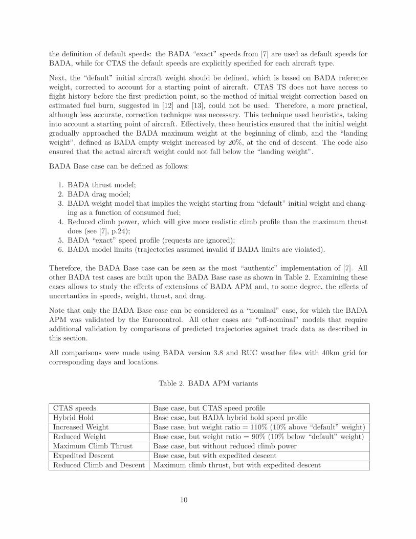
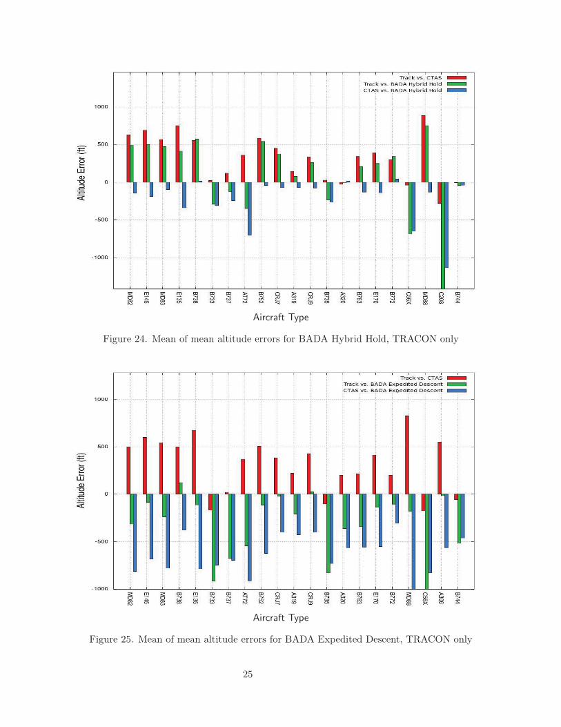
All results discussed so far were obtained using the BADA Base case. The BADA Hybrid Holdvariant performs similarly, but in the TRACON it reduces the values of mean of mean altitudeerrors for almost all most frequent aircraft types (except most of Boeing aircraft types), as shownin Figure 24.
The improvement over BADA Base case in TRACON area can be attributed to the fact thatin BADA Hybrid Hold case the BADA default speeds can be changed by client requests. Thisadvantage becomes even more apparent from comparisons with Denver 2009 descent data (seesection 5.4 below). For this reason, for other centers the BADA Hybrid Hold variant was usedrather than the BADA Base case.
The BADA Expedited Descent variant achieves even more reductions in altitude errors in theTRACON. As can be seen from Figure 25 the mean of mean altitude errors is significantly lowerthen in CTAS TS for most aircraft types including MD82, MD83, B752, E135 and E145. However,for some aircraft types the mean of mean altitude errors is much larger, as in the case of B733 andB737.
13

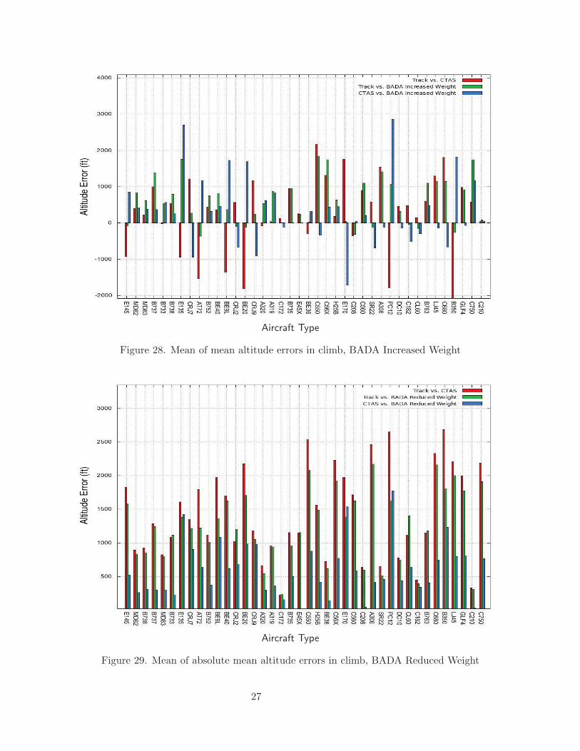
The plots for BADA reduced and increased weight variants, shown in Figures 26 through 31 com-pared with results for BADA Base case with nominal weight in Figures 6 and 7, demonstrate theeffect of weight uncertainty on prediction accuracy in climb. Again, these plots show the differentordering of aircraft types, because some flights can fly over the center and so the most frequentaircraft types for departing flights are not necessarily the same as for all flights.
The reduced weight variant (Figures 26 and 29) shows a very good improvement over the BADABase case in climbs. We can see that in contrast to the BADA Base case, the reduced weightvariant performs better than CTAS, rather than worse, for the mean of mean altitude errors forMD82, MD83, E135, B738, and B737 aircraft types. The mean of absolute mean altitude errorshave also improved for many aircraft types.
The effect of increased weight in climb is less pronounced as can be seen from Figures 28 and 31compared with Figures 27 and 30 for BADA Base case with nominal weight. This can be explainedby inverse dependency of ROCD, and hence the altitude, on aircraft weight, making the altitudeerrors less sensitive to weight when the weight increases. Using the BADA reduced climb powerfurther reduces this sensitivity as can be seen from equations (3.8-1) and (3.8-2) in [7].
It can be noted that CTAS default aircraft weights can also be adjusted to reduce errors of CTASAPM, although this is beyond the scope of this study.
One especially interesting BADA variant is the BADA with CTAS speeds since its comparison withCTAS APM allows to study separately the effect of the aircraft performance model for the samespeed profile. It is clear from Figures 32 and 33 that the BADA with CTAS speeds reduced thealtitude errors for most frequent aircraft types, except CRJ7 and CRJ9.
Aircraft Type
Figure 3. Most frequent aircraft types for Fort Worth center
14

Altitude Error (ft)
Figure 4. Overall mean altitude error, CTAS distribution
Altitude Error (ft)
Figure 5. Overall mean altitude error, BADA distribution
15

Aircraft Type
Figure 6. Mean of mean altitude errors
Aircraft Type
Figure 7. Mean of absolute mean altitude errors
16

Aircraft Type
Figure 8. Mean of mean along-track errors
Aircraft Type
Figure 9. Events, Mean of mean TOC time errors
17

Aircraft Type
Figure 10. Events, Mean of absolute mean TOC time errors
Aircraft Type
Figure 11. Events, Mean of mean TOD time errors
18

Aircraft Type
Figure 12. Events, Mean of absolute mean TOD time errors
Aircraft Type
Figure 13. Events, Mean of mean ETA time errors
19

Aircraft Type
Figure 14. Events, Mean of absolute mean ETA time errors
Look-ahead time (minutes)
Figure 15. Interval-based sampling, mean altitude error during climb
20

Look-ahead time (minutes)
Figure 16. Interval-based sampling, mean absolute altitude error during climb
Look-ahead time (minutes)
Figure 17. Interval-based sampling, standard deviation of altitude error during climb
21

Look-ahead time (minutes)
Figure 18. Interval-based sampling, mean altitude error during descent
Look-ahead time (minutes)
Figure 19. Interval-based sampling, mean absolute altitude error during descent
22

Look-ahead time (minutes)
Figure 20. Interval-based sampling, standard deviation of altitude error during descent
Aircraft Type
Figure 21. Most frequent aircraft types for samples with more than 10 flights in TRACON
23

Aircraft Type
Figure 22. Mean of mean altitude errors, TRACON only
Aircraft Type
Figure 23. Mean of absolute mean altitude errors, TRACON only
24
Aircraft Type
Figure 24. Mean of mean altitude errors for BADA Hybrid Hold, TRACON only
Aircraft Type
Figure 25. Mean of mean altitude errors for BADA Expedited Descent, TRACON only
25

Aircraft Type
Figure 26. Mean of mean altitude errors in climb, BADA Reduced Weight
Aircraft Type
Figure 27. Mean of mean altitude errors in climb, BADA Nominal Weight
26
Aircraft Type
Figure 28. Mean of mean altitude errors in climb, BADA Increased Weight
Aircraft Type
Figure 29. Mean of absolute mean altitude errors in climb, BADA Reduced Weight
27

Aircraft Type
Figure 30. Mean of absolute mean altitude errors in climb, BADA Nominal Weight
Aircraft Type
Figure 31. Mean of absolute mean altitude errors in climb, BADA Increased Weight
28

Aircraft Type
Figure 32. Mean of mean altitude errors for BADA with CTAS speeds
Aircraft Type
Figure 33. Mean of absolute mean altitude errors for BADA with CTAS speeds
29

Moreover, for aircraft types with largest altitude errors in CTAS, such as E145, E135, BE20, andBE9L, the BADA with CTAS speeds yields substantially better accuracy. These results demonstratethat the BADA APM is superior for the vast majority of aircraft types, and especially for smalleraircraft types, such as E145 and E135. At the same time, comparison of these plots with Figures6 and 7 does not show significant advantage of using BADA speeds (e.g. Base case variant) overCTAS speeds in terms of altitude accuracy.
5.2 Los Angeles Center (ZLA), 1 day
Using the same methodology, the radar track data for 1 day of traffic in Los Angeles center (ZLA)were compared with CTAS TS and BADA Hybrid Hold predictions.
Table 5 summarizes results obtained from these comparisons:
Table 5. Mean altitude and along-track errors for BADA Hybrid Hold for Los Angeles center
Error type Comparison Abs Max Mean Abs Mean Max Min Std Dev
Altitude (ft)CTAS vs. Track 25960 797 1966 22475 -25960 3507BADA vs. Track 25598 863 1963 19756 -25598 3492
Along-track(nm)
CTAS vs. Track 122.47 3.66 7.35 54.26 -122.47 8.9BADA vs. Track 125.94 3.83 6.73 51.59 -125.94 8.37
For this center BADA does not have clear advantages over CTAS in terms of altitude and along-track errors. This can be partially explained by the different aircraft type decomposition with mostfrequent aircraft type B737 rather than MD82, as evident from Figure 34.
The results plotted on Figures 35 and 36 show that for this center BADA clearly outperforms CTASin terms of altitude errors for A319, CRJ7, and CRJ9.
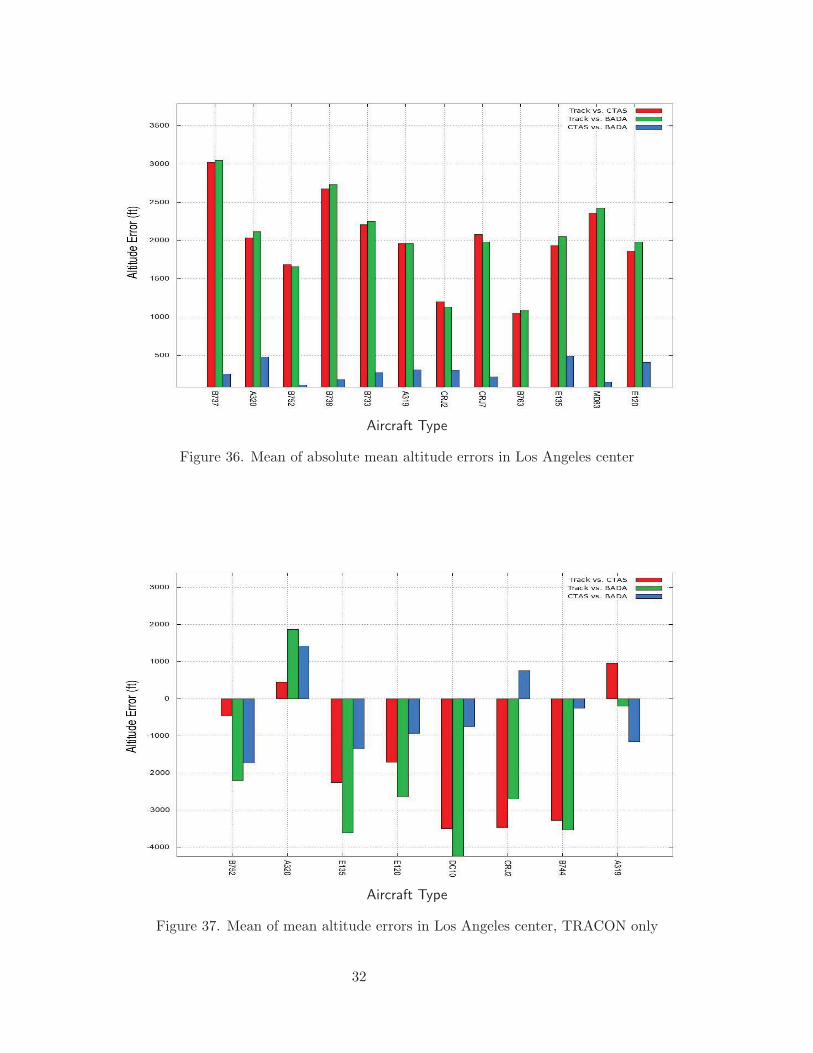
In TRACON area, BADA altitude errors are much lower in comparison with CTAS only for twoaircraft types - A319 and CRJ2, and consistently higher for all other aircraft as becomes apparentfrom Figures 37 and 38.
30

Aircraft Type
Figure 34. Most frequent aircraft types for samples with more than 10 flights in Los Angeles center
Aircraft Type
Figure 35. Mean of mean altitude errors in Los Angeles center
31
Aircraft Type
Figure 36. Mean of absolute mean altitude errors in Los Angeles center
Aircraft Type
Figure 37. Mean of mean altitude errors in Los Angeles center, TRACON only
32
Aircraft Type
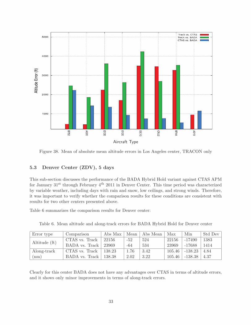
Figure 38. Mean of absolute mean altitude errors in Los Angeles center, TRACON only
5.3 Denver Center (ZDV), 5 days
This sub-section discusses the performance of the BADA Hybrid Hold variant against CTAS APMfor January 31st through February 4th 2011 in Denver Center. This time period was characterizedby variable weather, including days with rain and snow, low ceilings, and strong winds. Therefore,it was important to verify whether the comparison results for these conditions are consistent withresults for two other centers presented above.
Table 6 summarizes the comparison results for Denver center:
Table 6. Mean altitude and along-track errors for BADA Hybrid Hold for Denver center
Error type Comparison Abs Max Mean Abs Mean Max Min Std Dev
Altitude (ft)CTAS vs. Track 22156 -52 524 22156 -17490 1383BADA vs. Track 23969 -64 534 23969 -17688 1414
Along-track(nm)
CTAS vs. Track 138.23 1.76 3.42 105.46 -138.23 4.84BADA vs. Track 138.38 2.02 3.22 105.46 -138.38 4.37
Clearly for this center BADA does not have any advantages over CTAS in terms of altitude errors,and it shows only minor improvements in terms of along-track errors.
33

Once again, Figure 39 shows a different type decomposition; the most frequently observed aircrafttypes were the B737, A320, B752, and A319.
Aircraft Type
Figure 39. Most frequent aircraft types in Denver center
Figures 40 and 41 show uneven results for altitude errors, with BADA being substantially moreaccurate for several aircraft types (CRJ7, E170, B190, BE20, C750, MD82, BE9L), and CTASmuch more accurate for other aircraft types (CRJ2, C560, C56X, E120, LJ35). However, theoverall BADA performance is affected by the fact that BADA is a little less accurate for the fouraircraft types most frequently observed in Denver center: B737, A320, B752, and A319.
It is interesting to note that BADA is much more accurate than CTAS in predicting TOC for thevast majority of the most frequently observed aircraft types. This is consistent with results forLos Angeles Center and for several BADA variants for Fort Worth Center as well (compare, forinstance, Figure 9 with Figure 42).
34

Aircraft Type
Figure 40. Mean of mean altitude errors in Denver center
Aircraft Type
Figure 41. Mean of absolute mean altitude errors in Denver center
35

Aircraft Type
Figure 42. Mean of absolute mean TOC time errors in Denver center
5.4 Off-nominal conditions, Denver 2009
We could have seen already from comparison between Figures 24 and 22 that the BADA HybridHold variant showed a similar or even better performance than the BADA Base case. This findingcould be seen as an indirect evidence of relative insensitivity of BADA accuracy to limited deviationsfrom nominal BADA speeds, allowed by BADA Hybrid Hold speed profile.
However, it was desirable to study the effect of off-nominal speeds for better controlled conditionswith reduced uncertainty in aircraft weight, speed, and pilot intent. This was done by utilizingthe data collected in Denver in 2009, which included descending flights performed according topredefined descent profiles. The data set for Denver-2009 included, in addition to cm sim fileswith radar tracks, the weather Rapid Update Cycle (RUC) files, the data for advisory descentspeeds and, for some flights, the actual descent weights. This is the same data set that was usedin study [11].
We used for this analysis the CmSimTrackComparer tool, which generated the predictions andcalculated their errors for all tracks from cm sim files for the filtered set of flights. Filtering wasnecessary for two reasons:
• The flights with missing/inconsistent data, e.g. all flights not listed in the input files givento us for Denver-2009 data set, had to be excluded,
• CmSimTrackComparer does not parse the route from the flight plan, so the flights withcross-track error exceeding 10 nm were filtered out in order to analyze only the flights close
36

to direct-to routes.
After this filtering our analysis included more than 40 thousand predictions for 256 flights.
Tables 7 and 8 summarize the comparison results for path- and time-based correlations:
Table 7. Mean altitude errors (ft), path-based correlations
Test case Abs Max Mean Abs Mean Max Min Std DevCTAS TS 11667 -192 505 11667 -5113 760BADA Hybrid Hold 11528 -433 563 11528 -10608 759BADA Base Case 10276 -960 1014 10276 -5987 815
Table 8. Mean altitude errors (ft), time-based correlations
Test case Abs Max Mean Abs Mean Max Min Std DevCTAS TS 21426 -427 846 21426 -4527 1158BADA Hybrid Hold 21515 -673 930 21515 -13799 1136BADA Base Case 20981 -632 1099 20981 -5404 1330
As can be seen from these tables, the altitude errors for time-based correlations are significantlyhigher than for path-based correlations. This is not surprising because location and altitude ofthe final prediction point in our analysis were determined from the meterfix position and crossingaltitude, while the meterfix crossing time was affected by along-track errors.
However, even for path-based correlations the BADA Base case is substantially less accurate thanCTAS or BADA Hybrid Hold. This is explained by the fact that ignoring the commanded descent,descent and control speeds results in inaccurate TOD positions and hence in large altitude errors.This can be illustrated by plots for one flight of Boeing 757-200 aircraft, shown on Figures 43 and44.
It is interesting to note that the BADA Hybrid Hold model performs almost as well as the CTASmodel, with the mean absolute altitude error and standard deviation of altitude error being slightlylarger. This can be explained by noting that the advised descent and initial Mach do not differmuch from the BADA recommended speeds, hence the altitude profile becomes more accurate.This can be observed from the plots shown on Figures 45 and 46 for the same flight.
Further analysis is required to determine if BADA accuracy will suffer for off-nominal conditions.These limited results indicate that the performance of BADA APM in idle descents may be similaror slightly worse in comparison with CTAS APM for advised speeds that do not differ significantlyfrom the BADA advised speeds.
37

Figure 43. Boeing 757-200 BADA Base Case idle descent: ground speed
Figure 44. Boeing 757-200 BADA Base Case idle descent: altitude
38

Figure 45. Boeing 757-200 BADA Hybrid Hold idle descent: ground speed
Figure 46. Boeing 757-200 BADA Hybrid Hold idle descent: altitude
39

6 Conclusion
The BADA performance and operational model was integrated into the CTAS TS, the core com-putational engine of CTAS software. The integrated CTAS/BADA TS software incorporated allpossible variants of the BADA model, along with the native CTAS model. The CTAS/BADA TSsoftware was thoroughly validated by comparison of predictions for the BADA Base case with theBADA PTD file reference and other available benchmark data.
To assess the accuracy of CTAS/BADA TS for different variants of BADA APM, several validationtools for interval-based sampling and systematic analysis were developed and used to perform theanalysis for three different centers, Fort Worth, Los Angeles, and Denver, and for several BADAvariants over Fort Worth center.
The following observations can be made from these comparisons:
• In general, some BADA variants perform as well or slightly better than CTAS in terms ofaltitude and along-track errors.
• Cross-track errors are mostly related to intent errors and flight plan amendments, so theyremain practically the same for BADA and CTAS.
• Overall the differences between BADA and CTAS in terms of mean of absolute mean errorsare relatively small (a few percent of error magnitudes) and statistically insignificant.
• There is no one BADA variant that would improve performance for all flight phases and allaircraft types.
• BADA has more accurate models for many aircraft types, such as AT72, BE20, BE36, BE9L,CRJ7, E145, PC12, and SR22. These are mostly small or regional aircraft.
• CTAS has more accurate models for A319, A320, B190, B733, B737, B738, C182, C56X, andE120. Most notably these aircraft types include large commercial aircraft from Airbus andBoeing.
• Both CTAS and BADA have good models for several aircraft types - A306, B752, C750,CRJ2, CRJ9, E135, E170, H25B, MD82, and MD83, including popular McDonnell Douglas,Embraer, and Canadair aircraft.
• BADA is found to be most beneficial in climb, especially with the BADA Reduced Weightvariant.
• Typically BADA is much more accurate than CTAS in predicting Top Of Climb (TOC) forthe most prevalent aircraft types.
• When compared with CTAS, BADA has slightly worse performance in descent, especially forBoeing aircraft types that have very good models in CTAS. However, BADA performance fordescents can be improved by using the BADA Hybrid Hold variant with speeds responding toclient requests, or the BADA Expedited Descent reducing the altitude errors for most aircrafttypes in the TRACON.
• Most BADA variants fail more frequently than CTAS, mainly due to inconsistency in defini-tion of maximum operating altitude in BADA, where it is defined as aircraft-specific, and inCTAS TS, where the value of 60, 000 ft is used for all aircraft types.
Our performance metrics did not include fuel consumption. It is known that the BADA fuelconsumption model works well in cruise, but does not perform in climb and descent as accuratelycompared with cruise (see [14]).
40

The analysis of BADA off-nominal performance with controlled cruise and descent speeds confirmedthat
• the BADA Base Case was substantially less accurate for descents than CTAS;• the BADA Hybrid Hold variant performed almost as well as CTAS TS did.
Finally, on the basis of this limited analysis we can conclude that using BADA APM with “hybridhold” speed profile and expedited descent can improve the accuracy of CTAS for small and regionalaircraft types. More substantial improvement in prediction accuracy can be expected using adaptiveestimation of aircraft parameters, such as speed and weight, from historical track data for eachflight.
Acknowledgments
This work would not have been possible without help and support from many people. We especiallywant to express our gratitude to Karen Cate for her guidance, to Hassan Eslami for continuoussupport and encouragement, to Martin Brown for contributions in data analysis and developmentof validation tools, to Alan Lee and Steven Chan for invaluable help in studying the existing CTASTS code, to Gano Chatterji and Gilbert Wu for valuable discussions, to Jinn-Hwei Cheng for allher help with check-ins and ClearCase issues, to Pat O’Neal for assistance with data analysis forDenver-2009, and to Laurel Stell for providing data sets for Denver-2009.
References
1. Erzberger, H., Davis, T. J., Green, S. M., Design of Center-TRACON Automation System,Proceedings of the AGARD Guidance and Control Panel 56th Symposium on Machine Intelligencein Air-Traffic Management, Berlin, GDR, 1993, pp. 52-1 - 14.
2. Slattery, R. A., Terminal Area Trajectory Synthesis for Air Traffic Control Automation, Pro-ceedings of the 1995 American Control Conference, Seattle, WA, 1995, pp. 1206-1210.
3. Slattery, R. A., and Zhao, Y., Trajectory Synthesis for Air Traffic Automation, Journal ofGuidance, Control and Dynamics, Vol. 20, No. 2, March-April 1997, pp. 232-238.
4. Lee, A. G., Bouyssounouse, X., Murphy, J. R., The Trajectory Synthesizer Generalized ProfileInterface, 10th AIAA Aviation Technology, Integration, and Operations (ATIO) Conference, FortWorth, TX, 13-15 Sep. 2010.
5. Chan, W., Bach, R., Walton, J., Improving and Validating CTAS Performance Models, AIAA-2000-4476, AIAA Guidance, Navigation, and Control Conference and Exhibit, Denver, CO, 14-17August 2000.
6. Gong, C, and McNally, D., A Methodology for Automated Trajectory Prediction Analysis, AIAA-2004-4788, AIAA Guidance, Navigation, and Control Conference, Providence, RI, 16-19 Aug.2004.
41

7. Eurocontrol Experimental Centre, User Manual for the Base of Aircraft DATA (BADA) Revision3.8, EEC Technical/Scientific Report No. 2010-003, 2010.
8. Eurocontrol Experimental Centre, Base of Aircraft DATA (BADA) Aircraft Performance Mod-elling Report, EEC Technical/Scientific Report No. 2009-009, 2009.
9. Oaks, R. D., Ryan, H. F., Paglione, M. Prototype Implementation and Concept Validation of a4-D Trajectory Fuel Burn Model Application, AIAA 2010-8164, AIAA Guidance, Navigation, andControl Conference, Toronto, Ontario Canada, 2010.
10. Paglione, M and Oaks, R. Implementation and Metrics for a Trajectory Prediction ValidationMethodology, AIAA-2007-6517, AIAA Guidance, Navigation, and Control Conference, HiltonHead, SC, 2007.
11. Stell, L., Predictability of Top of Descent Location for Operational Idle-Thrust Descents, 10thAIAA Aviation Technology, Integration, and Operations (ATIO) Conference, Fort Worth, TX,13-15 Sep. 2010.
12. Lee, H and Chatterji, G. B. Closed Form Takeoff Weight Estimation Model for Air Transporta-tion Simulation, AIAA 2010-9156, 10th AIAA Aviation Technology, Integration, and Operations(ATIO) Conference, Fort Worth, TX, 13-15 Sep. 2010.
13. Chatterji, G. B. Fuel Burn Estimation Using Real Track Data, AIAA-2011-6881, 11th AIAAAviation Technology, Integration, and Operations (ATIO) Conference, Virginia Beach, VA, 20-22Sep. 2011.
14. Senzig, D., Fleming, G., and Iovinelli, R. Fuel consumption modeling in support of ATM envi-ronmental decision-making, Proceedings of the Eighth Annual FAA/EUROCONTROL Air TrafficManagement Research and Development Seminar, Napa, CA, June 29-July 2, 2009.
42

Appendix A
Example of the BADA Operation Performance File
CCCCCCCCCCCCCCCCCCCCCCCCCCCCCC P28A__.OPF CCCCCCCCCCCCCCCCCCCCCCCCCCCC/CC /CC AIRCRAFT PERFORMANCE OPERATIONAL FILE /CC /CC /CC File_name: P28A__.OPF /CC /CC Creation_date: Apr 30 2002 /CC /CC Modification_date: Nov 10 2008 /CC /CC /CC====== Actype ======================================================/CD P28A__ 1 engines Piston L /CC Piper PA-28-161 CW with Lycoming-O-320-D3G engines wake /CC /CC====== Mass (t) ====================================================/CC reference minimum maximum max payload mass grad /CD .10550E+01 .61300E+00 .11060E+01 .33000E+00 .00000E+00 /CC====== Flight envelope =============================================/CC VMO(KCAS) MMO Max.Alt Hmax temp grad /CD .12600E+03 .24000E+00 .12000E+05 .00000E+00 .00000E+00 /CC====== Aerodynamics ================================================/CC Wing Area and Buffet coefficients (SIM) /CCndrst Surf(m2) Clbo(M=0) k CM16 /CD 5 .15790E+02 .00000E+00 .00000E+00 .00000E+00 /CC Configuration characteristics /CC n Phase Name Vstall(KCAS) CD0 CD2 unused /CD 1 CR Clean .50000E+02 .15315E-01 .41587E-01 .00000E+00 /CD 2 IC Clean .50000E+02 .00000E+00 .00000E+00 .00000E+00 /CD 3 TO Flap25 .48000E+02 .00000E+00 .00000E+00 .00000E+00 /CD 4 AP Flap40 .43000E+02 .00000E+00 .00000E+00 .00000E+00 /CD 5 LD Flap40 .43000E+02 .00000E+00 .00000E+00 .00000E+00 /CC Spoiler /CD 1 RET /CD 2 EXT .00000E+00 .00000E+00 /CC Gear /CD 1 UP /CD 2 DOWN .00000E+00 .00000E+00 .00000E+00 /CC Brakes /
43

CD 1 OFF /CD 2 ON .00000E+00 .00000E+00 /CC====== Engine Thrust ===============================================/CC Max climb thrust coefficients (SIM) /CD .11167E+04 .28192E+05 .88240E+04 .00000E+00 .35552E-02 /CC Desc(low) Desc(high) Desc level Desc(app) Desc(ld) /CD .16007E+00 .00000E+00 .43850E+04 .16007E+00 .38908E-01 /CC Desc CAS Desc Mach unused unused unused /CD .12600E+03 .24000E+00 .00000E+00 .00000E+00 .00000E+00 /CC====== Fuel Consumption ============================================/CC Thrust Specific Fuel Consumption Coefficients /CD .44515E+00 .00000E+00 /CC Descent Fuel Flow Coefficients /CD .30872E+00 .00000E+00 /CC Cruise Corr. unused unused unused unused /CD .87274E+00 .00000E+00 .00000E+00 .00000E+00 .00000E+00 /CC====== Ground ======================================================/CC TOL LDL span length unused /CD .50300E+03 .35400E+03 .10670E+02 .72500E+01 .00000E+00 /CC====================================================================/FI /
44

Appendix B
Example of the BADA Performance Table Data File
Not all columns in the following table are shown due to a page width limitation.
BADA PERFORMANCE FILE RESULTS==========================================================
Low mass CLIMBS===============
FL[-] T[K] p[Pa] rho[kg/m3] a[m/s] TAS[kt] CAS[kt] M[-] mass[kg] Thrust[N] Drag[N]0 288 101325 1.225 340 72.12 72.12 0.11 736 1239 3675 287 99508 1.207 340 79.58 79.00 0.12 736 1208 380
10 286 97717 1.190 339 80.16 79.00 0.12 736 1187 38015 285 95952 1.172 339 80.75 79.00 0.12 736 1167 38020 284 94213 1.155 338 81.35 79.00 0.12 736 1146 38030 282 90812 1.121 337 82.57 79.00 0.13 736 1105 38040 280 87511 1.088 336 83.81 79.00 0.13 736 1064 38060 276 81200 1.024 333 86.37 79.00 0.13 736 981 38080 272 75262 0.963 331 89.05 79.00 0.14 736 899 380
100 268 69682 0.905 328 91.86 79.00 0.14 736 817 380120 264 64441 0.849 326 94.79 79.00 0.15 736 734 380
Medium mass CLIMBS==================
FL[-] T[K] p[Pa] rho[kg/m3] a[m/s] TAS[kt] CAS[kt] M[-] mass[kg] Thrust[N] Drag[N]0 288 101325 1.225 340 79.00 79.00 0.12 1055 1228 5235 287 99508 1.207 340 79.58 79.00 0.12 1055 1208 523
10 286 97717 1.190 339 80.16 79.00 0.12 1055 1187 52315 285 95952 1.172 339 80.75 79.00 0.12 1055 1167 52320 284 94213 1.155 338 81.35 79.00 0.12 1055 1146 52330 282 90812 1.121 337 82.57 79.00 0.13 1055 1105 52340 280 87511 1.088 336 83.81 79.00 0.13 1055 1064 52360 276 81200 1.024 333 86.37 79.00 0.13 1055 981 52380 272 75262 0.963 331 89.05 79.00 0.14 1055 899 523
100 268 69682 0.905 328 91.86 79.00 0.14 1055 817 523120 264 64441 0.849 326 94.79 79.00 0.15 1055 734 523
45

High mass CLIMBS================
FL[-] T[K] p[Pa] rho[kg/m3] a[m/s] TAS[kt] CAS[kt] M[-] mass[kg] Thrust[N] Drag[N]0 288 101325 1.225 340 79.00 79.00 0.12 1106 1228 5515 287 99508 1.207 340 79.58 79.00 0.12 1106 1208 551
10 286 97717 1.190 339 80.16 79.00 0.12 1106 1187 55115 285 95952 1.172 339 80.75 79.00 0.12 1106 1167 55120 284 94213 1.155 338 81.35 79.00 0.12 1106 1146 55130 282 90812 1.121 337 82.57 79.00 0.13 1106 1105 55140 280 87511 1.088 336 83.81 79.00 0.13 1106 1064 55160 276 81200 1.024 333 86.37 79.00 0.13 1106 981 55180 272 75262 0.963 331 89.05 79.00 0.14 1106 899 551
100 268 69682 0.905 328 91.86 79.00 0.14 1106 817 551120 264 64441 0.849 326 94.79 79.00 0.15 1106 734 551
Medium mass DESCENTS====================
FL[-] T[K] p[Pa] rho[kg/m3] a[m/s] TAS[kt] CAS[kt] M[-] mass[kg] Thrust[N] Drag[N]0 288 101325 1.225 340 60.90 60.90 0.09 1055 49 6145 287 99508 1.207 340 66.38 65.90 0.10 1055 197 571
10 286 97717 1.190 339 77.02 75.90 0.12 1055 191 52815 285 95952 1.172 339 128.78 126.00 0.20 1055 180 73220 284 94213 1.155 338 129.72 126.00 0.20 1055 177 73230 282 90812 1.121 337 131.65 126.00 0.20 1055 170 73140 280 87511 1.088 336 133.61 126.00 0.20 1055 164 73160 276 81200 1.024 333 137.66 126.00 0.21 1055 0 73180 272 75262 0.963 331 141.90 126.00 0.22 1055 0 730
100 268 69682 0.905 328 146.33 126.00 0.23 1055 0 730120 264 64441 0.849 326 150.95 126.00 0.24 1055 0 729
TDC stands for (Thrust - Drag) * Cred
46