Integrating Microsoft Hyper-V Virtualization of SharePoint 2007 ... - Cisco€¦ · Microsoft SQL...
74
Integrating Microsoft Hyper-V Virtualization of SharePoint 2007 into a Cisco Data Center Infrastructure Using Cisco UCS and Application Services Last Updated: March 31, 2010 Building Architectures to Solve Business Problems
Transcript of Integrating Microsoft Hyper-V Virtualization of SharePoint 2007 ... - Cisco€¦ · Microsoft SQL...
Integrating Microsoft Hyper-V Virtualization of SharePoint 2007 into a Cisco Data Center Infrastructure Using Cisco UCS and Application Services Last Updated: March 31, 2010
Building Architectures to Solve Business Problems

Cisco Validated Design2
About the Authors
Chris Obrien
3
Aeisha Duncan
Solution Authors
Chris Obrien, Solutions Architect, CMO Enterprise Solutions Engineering (ESE), Cisco SystemsChris is a Solutions Architect for data center technologies in Cisco's Enterprise Solutions Engineering group. He is currently focused on data center design validation and application optimization. Previously, Chris was an application developer and has been working in the IT industry for more than 15 years.
Aeisha Bright, Technical Marketing Engineer, CMO Enterprise Solutions Engineering (ESE), Cisco SystemsAeisha, CCIE #13455, is a Technical Marketing Engineer for data center technologies in Cisco's Enter-prise Solutions Engineering group. Prior to joining the ESE team, Aeisha spent 4 years as a Customer Support Engineer in Cisco's Technical Assistance Center where she supported LAN switching, VPN, and Firewall technologies. She earned a B.S. in Computer Science from the University of Maryland at Balti-more County and an M.S. in Computer Networking from North Carolina State University.
C O N T E N T S
Solution Overview 6
Solution Architecture 7
SharePoint Application Overview 7
Data Center Overview 8
Benefits of This Solution 10
Solution Components 11
Solution Architecture 13
Design Details 13
Data Center Architecture—Ethernet 13
Server Farm Architecture 23
Application Architecture 38
WAN/Branch Architecture 48
Management 50
Conclusion 60
Appendix A—WAAS Mobile Configuration 60
Cisco WAAS Mobile Client Configuration 60
Cisco WAAS Mobile Server 63
Appendix B—WAAS Configuration 65
Appendix C—ACE Configuration 68
Appendix D—Windows-Based QoS 71
Additional References 73
About Cisco Validated Design (CVD) Program 73
4

Integrating Microsoft Hyper-V Virtualization of SharePoint 2007 into a Cisco Data Center Infrastructure Using Cisco UCS and Application Services
This document describes an architecture for the deployment of the Microsoft Office SharePoint 2007 and Microsoft SQL Server 2008 using the Cisco Unified Computing System (UCS) with Microsoft Hyper-V virtualization. This document provides guidance to engineers interested in deploying Cisco Data Center 3.0 architectures including network, compute, and application services. The design options and implementation details provided are intended to be a reference for an enterprise data center.
This document is intended for enterprises interested in an end-to-end solution for deploying Microsoft Office SharePoint 2007and Microsoft SQL Server 2008 in a Microsoft Hyper-V virtualized environment using Cisco UCS, Cisco ACE, and Cisco WAAS technologies.
Solution OverviewData centers have grown at such a rate that virtualization and consolidation are needed to keep them manageable and profitable. The various areas of data center architecture (server, network, and storage) are often managed in separate silos, which can lead to increased complexity and cost for current data centers.
Reliable application delivery is the main purpose of the data center, and thus often drives the architecture design. Microsoft SharePoint 2007 is a popular core application that is typically deployed in an enterprise data center. With virtualization becoming more mature and widely used, enterprises are now looking to virtualize and consolidate this application and other core applications in the data center without the loss of reliability or functionality.
With the introduction of the Cisco UCS, server, network, and storage virtualized deployment can now be more tightly coupled. A single device can now manage these separate areas of the data center architecture. This design guide describes an end-to-end virtualized deployment for SharePoint 2007 using the Cisco UCS and Cisco Data Center 3.0 network architecture.
Corporate Headquarters:
Copyright © 2009 Cisco Systems, Inc. All rights reserv
Cisco Systems, Inc., 170 West Tasman Drive, San Jose, CA 95134-1706 USA
Solution Overview
Included in the Cisco Data Center 3.0 architecture are intelligent network services providing security, availability, scalability, and improved performance to the Microsoft application environment. Cisco ACE and Cisco WAAS were used to enhance the end-user experience with Microsoft Office SharePoint 2007. These services are introduced transparently to the application, server administrator, and most importantly, the end user.
Solution Architecture
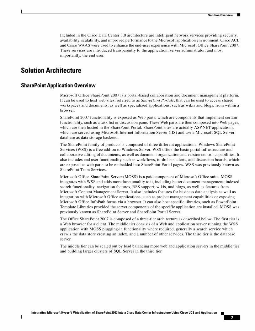
SharePoint Application Overview
Microsoft Office SharePoint 2007 is a portal-based collaboration and document management platform. It can be used to host web sites, referred to as SharePoint Portals, that can be used to access shared workspaces and documents, as well as specialized applications, such as wikis and blogs, from within a browser.
SharePoint 2007 functionality is exposed as Web parts, which are components that implement certain functionality, such as a task list or discussion pane. These Web parts are then composed into Web pages, which are then hosted in the SharePoint Portal. SharePoint sites are actually ASP.NET applications, which are served using Microsoft Internet Information Server (IIS) and use a Microsoft SQL Server database as data storage backend.
The SharePoint family of products is composed of three different applications. Windows SharePoint Services (WSS) is a free add-on to Windows Server. WSS offers the basic portal infrastructure and collaborative editing of documents, as well as document organization and version control capabilities. It also includes end user functionality such as workflows, to-do lists, alerts, and discussion boards, which are exposed as web parts to be embedded into SharePoint Portal pages. WSS was previously known as SharePoint Team Services.
Microsoft Office SharePoint Server (MOSS) is a paid component of Microsoft Office suite. MOSS integrates with WSS and adds more functionality to it, including better document management, indexed search functionality, navigation features, RSS support, wikis, and blogs, as well as features from Microsoft Content Management Server. It also includes features for business data analysis as well as integration with Microsoft Office applications, such as project management capabilities or exposing Microsoft Office InfoPath forms via a browser. It can also host specific libraries, such as PowerPoint Template Libraries provided the server components of the specific application are installed. MOSS was previously known as SharePoint Server and SharePoint Portal Server.
The Office SharePoint 2007 is composed of a three-tier architecture as described below. The first tier is a Web browser for a client. The middle tier consists of a Web and application server running the WSS application with MOSS plugging-in functionality where required, generally a search service which crawls the data store creating an index, and a number of other services. The third tier is the database server.
The middle tier can be scaled out by load balancing more web and application servers in the middle tier and building larger clusters of SQL Server in the third tier.
7Integrating Microsoft Hyper-V Virtualization of SharePoint 2007 into a Cisco Data Center Infrastructure Using Cisco UCS and Application
Solution Overview
Data Center Overview
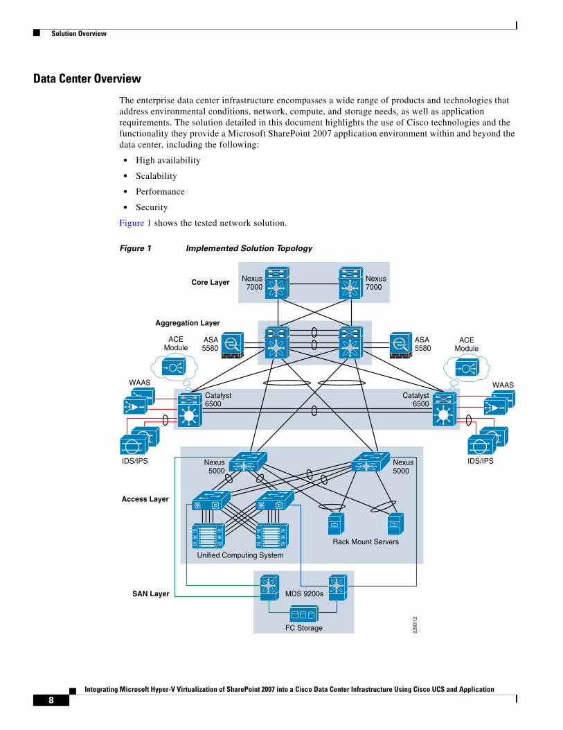
The enterprise data center infrastructure encompasses a wide range of products and technologies that address environmental conditions, network, compute, and storage needs, as well as application requirements. The solution detailed in this document highlights the use of Cisco technologies and the functionality they provide a Microsoft SharePoint 2007 application environment within and beyond the data center, including the following:
• High availability
• Scalability
• Performance
• Security
Figure 1 shows the tested network solution.
Figure 1 Implemented Solution Topology
Nexus7000
Catalyst6500
Catalyst6500
ASA5580
Access Layer
SAN Layer
ASA5580
Nexus7000
Core Layer
Aggregation Layer
Nexus5000
MDS 9200s
FC Storage
Nexus5000
ACEModule
ACEModule
WAAS WAAS
IDS/IPS
Unified Computing System
Rack Mount Servers
2283
12
IDS/IPS
8Integrating Microsoft Hyper-V Virtualization of SharePoint 2007 into a Cisco Data Center Infrastructure Using Cisco UCS and Application
Solution Overview
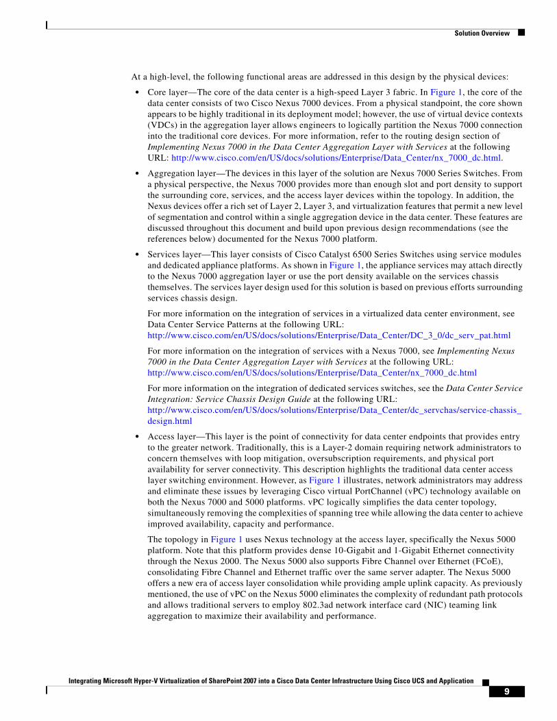
At a high-level, the following functional areas are addressed in this design by the physical devices:
• Core layer—The core of the data center is a high-speed Layer 3 fabric. In Figure 1, the core of the data center consists of two Cisco Nexus 7000 devices. From a physical standpoint, the core shown appears to be highly traditional in its deployment model; however, the use of virtual device contexts (VDCs) in the aggregation layer allows engineers to logically partition the Nexus 7000 connection into the traditional core devices. For more information, refer to the routing design section of Implementing Nexus 7000 in the Data Center Aggregation Layer with Services at the following URL: http://www.cisco.com/en/US/docs/solutions/Enterprise/Data_Center/nx_7000_dc.html.
• Aggregation layer—The devices in this layer of the solution are Nexus 7000 Series Switches. From a physical perspective, the Nexus 7000 provides more than enough slot and port density to support the surrounding core, services, and the access layer devices within the topology. In addition, the Nexus devices offer a rich set of Layer 2, Layer 3, and virtualization features that permit a new level of segmentation and control within a single aggregation device in the data center. These features are discussed throughout this document and build upon previous design recommendations (see the references below) documented for the Nexus 7000 platform.
• Services layer—This layer consists of Cisco Catalyst 6500 Series Switches using service modules and dedicated appliance platforms. As shown in Figure 1, the appliance services may attach directly to the Nexus 7000 aggregation layer or use the port density available on the services chassis themselves. The services layer design used for this solution is based on previous efforts surrounding services chassis design.
For more information on the integration of services in a virtualized data center environment, see Data Center Service Patterns at the following URL: http://www.cisco.com/en/US/docs/solutions/Enterprise/Data_Center/DC_3_0/dc_serv_pat.html
For more information on the integration of services with a Nexus 7000, see Implementing Nexus 7000 in the Data Center Aggregation Layer with Services at the following URL: http://www.cisco.com/en/US/docs/solutions/Enterprise/Data_Center/nx_7000_dc.html
For more information on the integration of dedicated services switches, see the Data Center Service Integration: Service Chassis Design Guide at the following URL: http://www.cisco.com/en/US/docs/solutions/Enterprise/Data_Center/dc_servchas/service-chassis_design.html
• Access layer—This layer is the point of connectivity for data center endpoints that provides entry to the greater network. Traditionally, this is a Layer-2 domain requiring network administrators to concern themselves with loop mitigation, oversubscription requirements, and physical port availability for server connectivity. This description highlights the traditional data center access layer switching environment. However, as Figure 1 illustrates, network administrators may address and eliminate these issues by leveraging Cisco virtual PortChannel (vPC) technology available on both the Nexus 7000 and 5000 platforms. vPC logically simplifies the data center topology, simultaneously removing the complexities of spanning tree while allowing the data center to achieve improved availability, capacity and performance.
The topology in Figure 1 uses Nexus technology at the access layer, specifically the Nexus 5000 platform. Note that this platform provides dense 10-Gigabit and 1-Gigabit Ethernet connectivity through the Nexus 2000. The Nexus 5000 also supports Fibre Channel over Ethernet (FCoE), consolidating Fibre Channel and Ethernet traffic over the same server adapter. The Nexus 5000 offers a new era of access layer consolidation while providing ample uplink capacity. As previously mentioned, the use of vPC on the Nexus 5000 eliminates the complexity of redundant path protocols and allows traditional servers to employ 802.3ad network interface card (NIC) teaming link aggregation to maximize their availability and performance.
9Integrating Microsoft Hyper-V Virtualization of SharePoint 2007 into a Cisco Data Center Infrastructure Using Cisco UCS and Application
Solution Overview
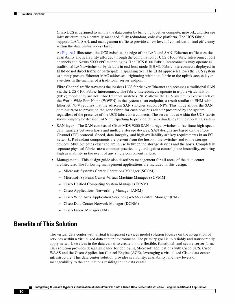
Cisco UCS is designed to simply the data center by bringing together compute, network, and storage infrastructure into a centrally managed, fully redundant, cohesive platform. The UCS fabric supports LAN, SAN, and management traffic to provide a new level of consolidation and efficiency within the data center access layer.
As Figure 1 illustrates, the UCS exists at the edge of the LAN and SAN. Ethernet traffic uses the availability and scalability afforded through the combination of UCS 6100 Fabric Interconnect port channels and Nexus 5000 vPC technologies. The UCS 6100 Fabric Interconnects may operate as traditional LAN switches or by default in end-host mode (EHM). Fabric interconnects deployed in EHM do not direct traffic or participate in spanning tree. The EHM approach allows the UCS system to simply present Ethernet MAC addresses originating within its fabric to the uplink access layer switches in the manner of a traditional server endpoint.
Fibre Channel traffic traverses the lossless UCS fabric over Ethernet and accesses a traditional SAN via the UCS 6100 Fabric Interconnect. The fabric interconnects operate in n-port virtualization (NPV) mode; they are not Fibre Channel switches. NPV allows the UCS system to expose each of the World Wide Port Name (WWPN) in the system as an endpoint, a result similar to EHM with Ethernet. NPV requires that the adjacent SAN switches support NPV. This mode allows the SAN administrator to provision the zone fabric for each host bus adapter presented by the system regardless of the presence of the UCS fabric interconnects. The server nodes within the UCS fabric should employ host-based SAN multipathing to provide fabric redundancy to the operating system.
• SAN layer—The SAN consists of Cisco MDS 9200 SAN storage switches to facilitate high-speed data transfers between hosts and multiple storage devices. SAN designs are based on the Fibre Channel (FC) protocol. Speed, data integrity, and high availability are key requirements in an FC network. Redundant components are present from the hosts to the switches and to the storage devices. Multiple paths exist and are in use between the storage devices and the hosts. Completely separate physical fabrics are a common practice to guard against control plane instability, ensuring high availability in the event of any single component failure.
• Management—This design guide also describes management for all areas of the data center architecture. The following management applications are included in this design:
– Microsoft Systems Center Operations Manager (SCOM)
– Microsoft Systems Center Virtual Machine Manager (SCVMM)
– Cisco Unified Computing System Manager (UCSM)
– Cisco Applications Networking Manager (ANM)
– Cisco Wide Area Application Services (WAAS) Central Manager (CM)
– Cisco Data Center Network Manager (DCNM)
– Cisco Fabric Manager (FM)
Benefits of This SolutionThe virtual data center with virtual transparent services model solution focuses on the integration of services within a virtualized data center environment. The primary goal is to reliably and transparently apply network services in the data center to create a more flexible, functional, and secure server farm. This solution provides design guidance for deploying Microsoft applications with Cisco UCS, Cisco WAAS and the Cisco Application Control Engine (ACE), leveraging a virtualized Cisco data center infrastructure. This data center solution provides scalability, availability, and new levels of manageability to the applications residing in the data center.
10Integrating Microsoft Hyper-V Virtualization of SharePoint 2007 into a Cisco Data Center Infrastructure Using Cisco UCS and Application
Solution Overview
Specifically, this solution design details the use of Microsoft Office SharePoint Server 2007 and SQL Server 2008 using Hyper-V virtualization technology within Cisco UCS. This document provides general guidelines on how to optimize and load balance these virtualized applications using Cisco WAAS and ACE. This document also provides a strategy to successfully deploy these virtualized Microsoft applications on a virtual Cisco data center infrastructure.
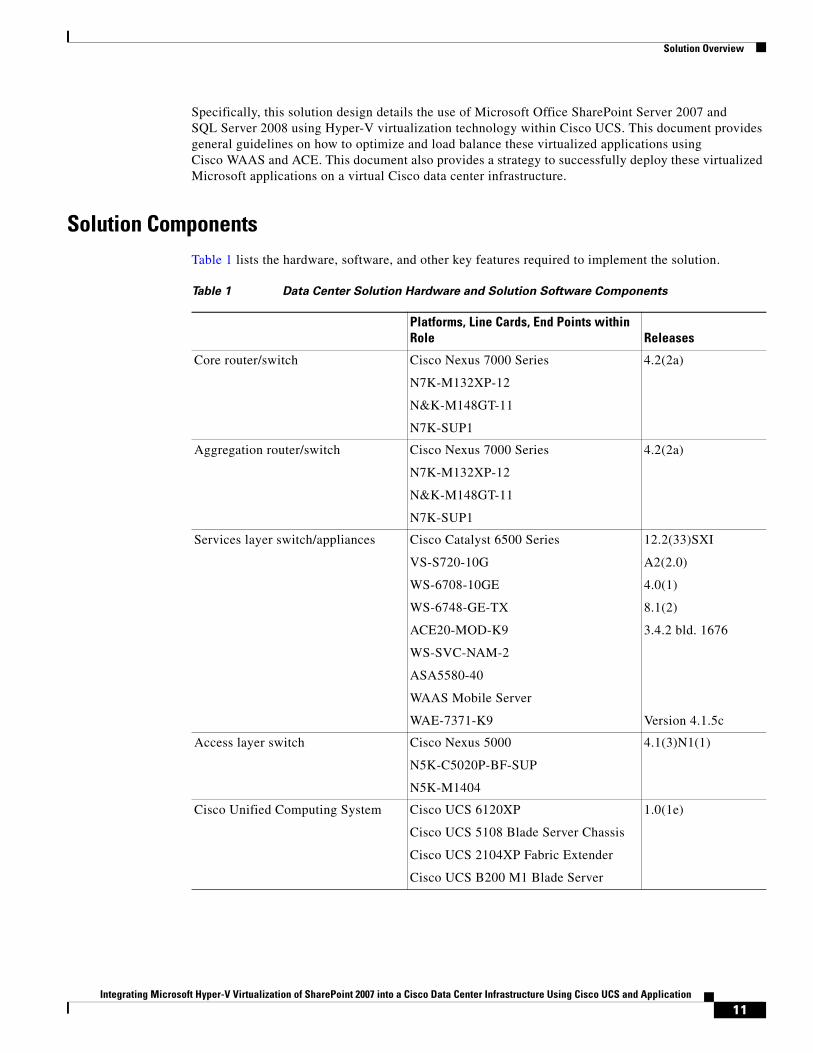
Solution ComponentsTable 1 lists the hardware, software, and other key features required to implement the solution.
Table 1 Data Center Solution Hardware and Solution Software Components
Platforms, Line Cards, End Points within Role Releases
Core router/switch Cisco Nexus 7000 Series
N7K-M132XP-12
N&K-M148GT-11
N7K-SUP1
4.2(2a)
Aggregation router/switch Cisco Nexus 7000 Series
N7K-M132XP-12
N&K-M148GT-11
N7K-SUP1
4.2(2a)
Services layer switch/appliances Cisco Catalyst 6500 Series
VS-S720-10G
WS-6708-10GE
WS-6748-GE-TX
ACE20-MOD-K9
WS-SVC-NAM-2
ASA5580-40
WAAS Mobile Server
WAE-7371-K9
12.2(33)SXI
A2(2.0)
4.0(1)
8.1(2)
3.4.2 bld. 1676
Version 4.1.5c
Access layer switch Cisco Nexus 5000
N5K-C5020P-BF-SUP
N5K-M1404
4.1(3)N1(1)
Cisco Unified Computing System Cisco UCS 6120XP
Cisco UCS 5108 Blade Server Chassis
Cisco UCS 2104XP Fabric Extender
Cisco UCS B200 M1 Blade Server
1.0(1e)
11Integrating Microsoft Hyper-V Virtualization of SharePoint 2007 into a Cisco Data Center Infrastructure Using Cisco UCS and Application
Solution Overview
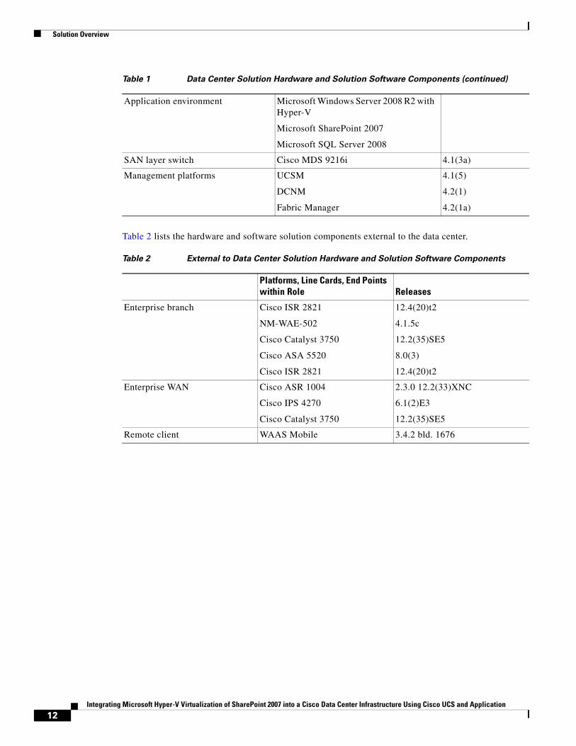
Table 2 lists the hardware and software solution components external to the data center.
Application environment Microsoft Windows Server 2008 R2 with Hyper-V
Microsoft SharePoint 2007
Microsoft SQL Server 2008
SAN layer switch Cisco MDS 9216i 4.1(3a)
Management platforms UCSM
DCNM
Fabric Manager
4.1(5)
4.2(1)
4.2(1a)
Table 1 Data Center Solution Hardware and Solution Software Components (continued)
Table 2 External to Data Center Solution Hardware and Solution Software Components
Platforms, Line Cards, End Points within Role Releases
Enterprise branch Cisco ISR 2821
NM-WAE-502
Cisco Catalyst 3750
Cisco ASA 5520
Cisco ISR 2821
12.4(20)t2
4.1.5c
12.2(35)SE5
8.0(3)
12.4(20)t2
Enterprise WAN Cisco ASR 1004
Cisco IPS 4270
Cisco Catalyst 3750
2.3.0 12.2(33)XNC
6.1(2)E3
12.2(35)SE5
Remote client WAAS Mobile 3.4.2 bld. 1676
12Integrating Microsoft Hyper-V Virtualization of SharePoint 2007 into a Cisco Data Center Infrastructure Using Cisco UCS and Application
Solution Architecture
Solution Architecture
Design DetailsThis section describes the following four elements of the design:
• Data Center Architecture—Ethernet, page 13
• Server Farm Architecture , page 23
• Application Architecture, page 38
• WAN/Branch Architecture, page 48
Data Center Architecture—Ethernet
Aggregation Layer Design Details
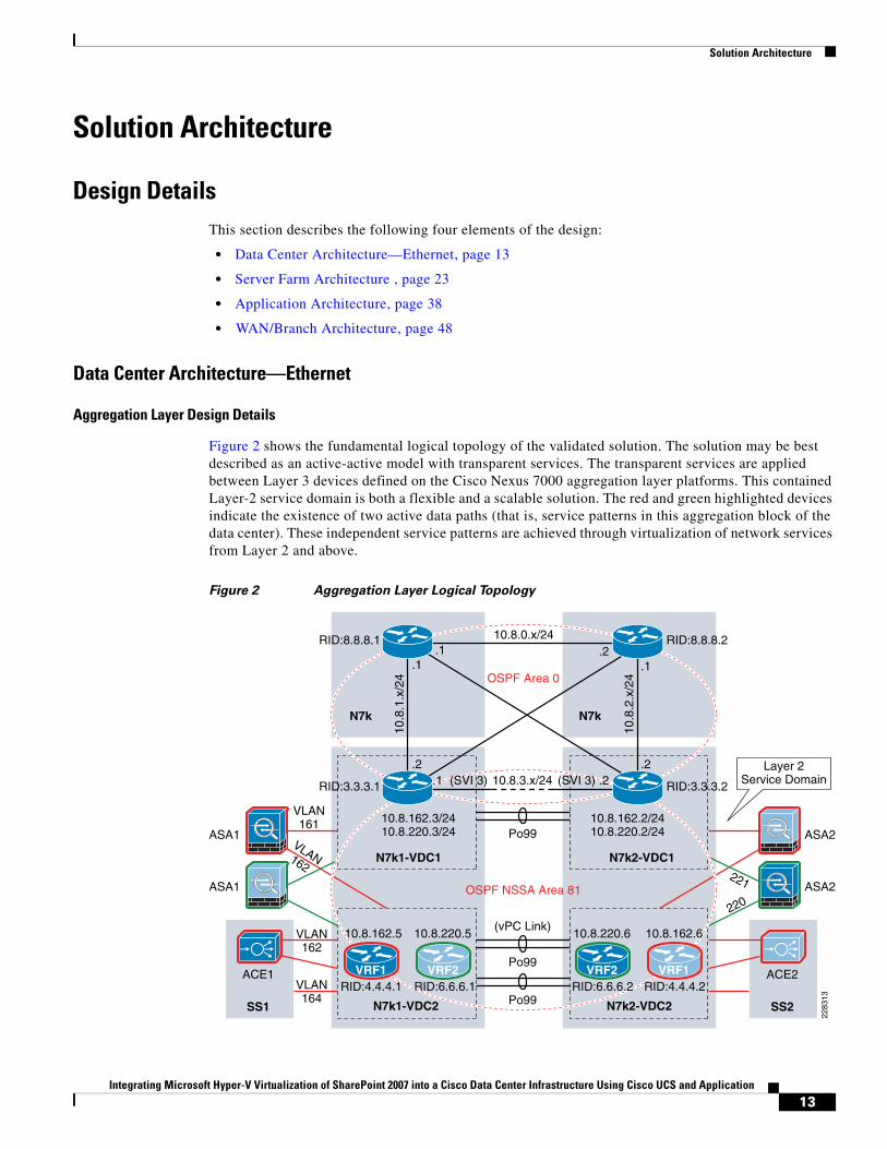
Figure 2 shows the fundamental logical topology of the validated solution. The solution may be best described as an active-active model with transparent services. The transparent services are applied between Layer 3 devices defined on the Cisco Nexus 7000 aggregation layer platforms. This contained Layer-2 service domain is both a flexible and a scalable solution. The red and green highlighted devices indicate the existence of two active data paths (that is, service patterns in this aggregation block of the data center). These independent service patterns are achieved through virtualization of network services from Layer 2 and above.
Figure 2 Aggregation Layer Logical Topology
ACE2
ASA2
ASA2
ASA1
Po99
Po99
10.8.220.610.8.220.5
10.8.162.3/2410.8.220.3/24
10.8.0.x/24.1 .2
.1 .1
.2 .2
10.8
.1.x
/24
10.8
.2.x
/24
RID:8.8.8.1 RID:8.8.8.2
RID:3.3.3.1 RID:3.3.3.2
10.8.162.2/2410.8.220.2/24
OSPF NSSA Area 81
OSPF Area 0
ASA1
ACE1
SS2SS1 N7k1-VDC2 N7k2-VDC2
N7k1-VDC1
N7k N7k
N7k2-VDC1
Po99
(vPC Link)
VRF1 VRF2 VRF1VRF2
10.8.162.610.8.162.5
.1 .210.8.3.x/24 (SVI 3)(SVI 3)
RID:4.4.4.1 RID:6.6.6.1 RID:6.6.6.2 RID:4.4.4.2
2283
13
VLAN161
VLAN162
VLAN164
VLAN162221
220
Layer 2Service Domain
13Integrating Microsoft Hyper-V Virtualization of SharePoint 2007 into a Cisco Data Center Infrastructure Using Cisco UCS and Application
Solution Architecture
The following is a brief description of the primary components shown in Figure 2:
• OSPF Area 0 is defined between the core Nexus 7000s and VDC1 on the aggregation layer Nexus 7000s. The Layer-2 port channel 99 (po99) supports all VLANs that exist between the VDC1 instances.
• Not-So-Stubby-Area 81 (NSSA Area 81) exists between VDC1 and virtual routing/forwarding (VRF) instances on VDC2. Note the use of alternating primary and standby VRFs to create an active-active Layer 3 topology. NSSA Area 81 also introduces a service layer consisting of active-active ASA and ACE virtual contexts attached directly to the Nexus aggregation switches or through dedicated services chassis.
Note The NSSA Area 81 may be expanded to include a myriad of services, such as intrusion detection and prevention, network analysis, and web-application firewall services transparently positioned between the Layer 3 devices of the NSSA Area 81. These functions are not discussed in this document but the ability to integrate and readily instantiate new services in the design addresses the flexibility requirements demanded by today’s data center administrators.
• Active-active ASA 5580 virtual contexts in transparent mode allow route adjacencies to form between VDC1 instances and VDC2 VRF devices to secure and optimize utilization of active-active data center resources. The use of the ASA virtual contexts between Nexus 7000 VDCs essentially creates a DMZ within the aggregation layer of the data center.
• Active-active ACE service module virtual contexts in transparent mode allow for neighboring devices between VDC1 and VDC2 VRF to optimize utilization of data center resources. In addition, the ACE virtual contexts provide application layer services such as load balancing, SSL offload, and session persistence. Note that these services are not shown applied to the active green data center path, implying that transparent virtual services may be selectively applied only to those server farm resources, (that is, applications) that require them.
• The vrf1 and vrf2 positioned in VDC2 of the Nexus 7000 aggregation block are the default gateways for their respective server farms. The default gateway is a Hot Standby Router Protocol (HSRP) group instance. Figure 2 shows this logical alignment of network services including application and security, default gateway, and spanning tree root through the red and green paths. In this example, the red data center pattern is active on the left side of the infrastructure while the green uses the right side of the aggregation block.
Note The use of multiple VRFs on the “southern” VDC, or in this example VDC2, may be advantageous to create an isolated Layer 3 topology for server-to-server traffic patterns or network monitoring traffic. In this effort, for example, dedicated failover clustering VLANs were restricted to the pair of “southern” VDCs and pertinent access layer switches.
Note The VLANs existing between VDC1 and VDC2 in Figure 2, specifically VLANs 161,162, 221, and 220, support Layer 3 communication protocols and are not present on any vPC links in the design. Cisco recommends configuring separate Layer 3 links for routing from the vPC peer devices, rather than using a VLAN network interface. For more information, see the “Guidelines and Limitations” section of the Cisco Nexus 7000 Series NX-OS Interfaces Configuration Guide at the following URL: http://www.cisco.com/en/US/docs/switches/datacenter/sw/4_2/nx-os/interfaces/configuration/guide/if_vPC.html#wp1559125.
14Integrating Microsoft Hyper-V Virtualization of SharePoint 2007 into a Cisco Data Center Infrastructure Using Cisco UCS and Application
Solution Architecture
Access Layer Design Details
The Cisco Nexus 5000 access layer is a flexible solution capable of providing a highly available Ethernet fabric to a multitude of server platforms. In this design, the Nexus 5000 switches are connected via vPC to the Nexus 7000 aggregation layer, specifically to the VDC2 instance defined on each platform. Each VDC implements a vPC connection to the Nexus 5000 platforms, which in turn implement a complementary vPC to form a single logical port channel between the aggregation and access layers.
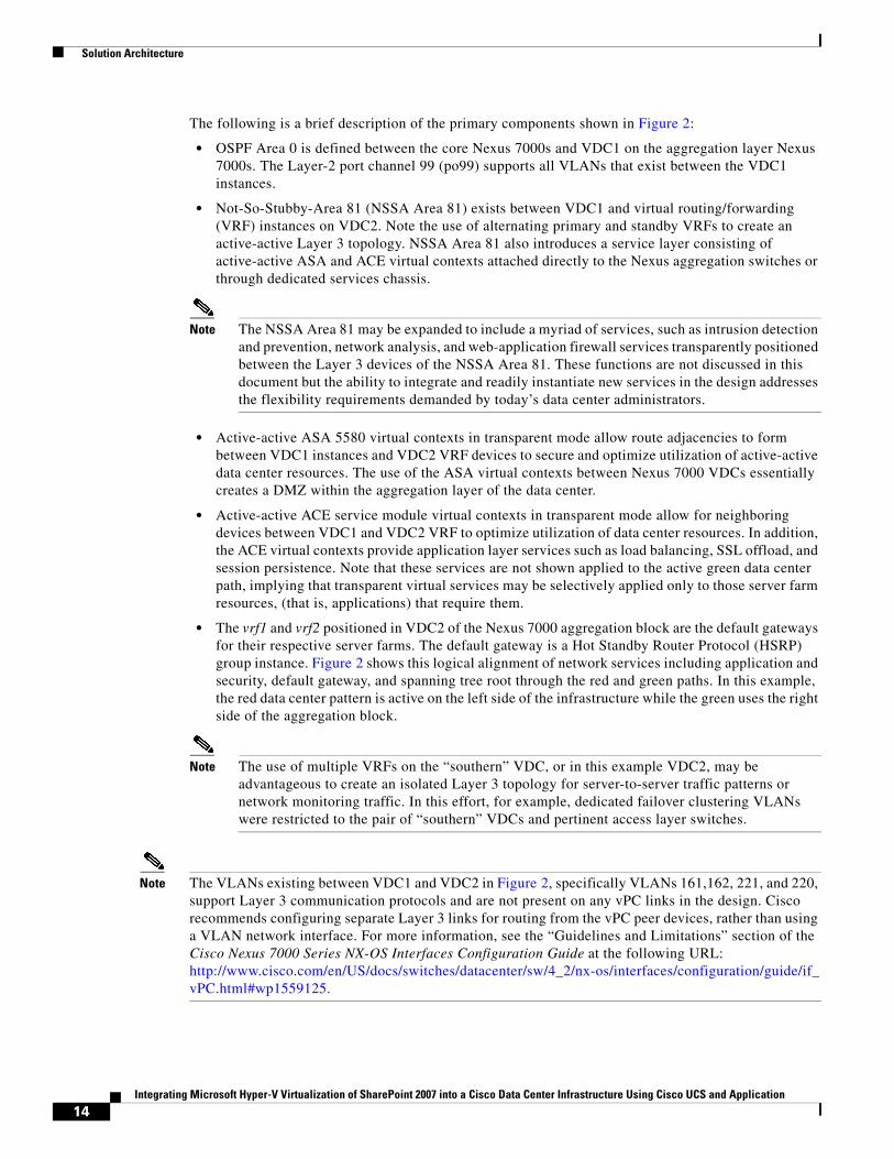
Figure 3 shows the physical connections from each chassis and the logical result of leveraging vPC technology in the solution implementation. The left side of Figure 3 shows that the Nexus 5000 and 7000 are dual-homed to each other and are leveraging virtual port channeling. In this example, vPC 3 resides on the Nexus 7000 aggregation layer and vPC 4 exists on the Nexus 5000 access layer pair. The right side of Figure 3 indicates that a single logical port channel exists as a result of the vPC configurations allowing or failing over based on link aggregation and not spanning tree.
Figure 3 DCNM PortChannel and vPC View of Access Layer—Logical Result
In addition to EtherChannel-based convergence, the use of vPC allows all paths to be used from the access layer and ultimately the servers it supports.
Figure 4, captured from the Nexus DCNM management console, confirms this point. In this example, the spanning tree domain topology for VLAN 180 is forwarding on all links (vPC links). Physically redundant paths are maintained without having to introduce logical blocks via spanning tree to contend with the loops this topology traditionally brings.
15Integrating Microsoft Hyper-V Virtualization of SharePoint 2007 into a Cisco Data Center Infrastructure Using Cisco UCS and Application

Solution Architecture
Figure 4 DCNM VLANs—STP View of Access Layer
Note Although vPC removes the traditional dependency on spanning tree in the access layer, it is considered a best practice to enable and define a spanning tree topology even though spanning tree is not actively defining the domain. Consider the use of spanning tree a defense-in-depth practice as it relates to high availability in the data center.
Services Layer Design Details
This section discusses the transparent integration of virtual services within the data center design. The design incorporates virtual instances of ASA firewalls and ACE virtual contexts to provide active-active service paths to the applications requiring these services in the server farm.
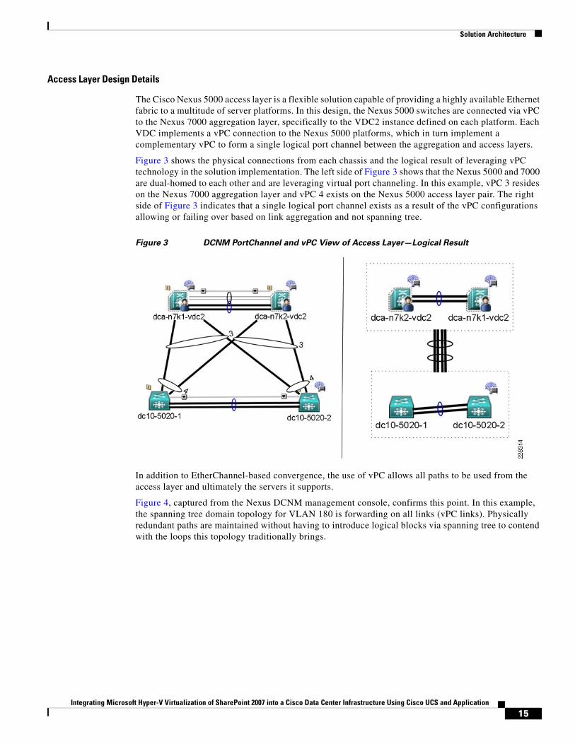
Figure 5 shows this concept.
16Integrating Microsoft Hyper-V Virtualization of SharePoint 2007 into a Cisco Data Center Infrastructure Using Cisco UCS and Application
Solution Architecture
Figure 5 Active-Active Data Center Service Patterns
The ASA and ACE virtual contexts are operating at Layer 2, stitching the “green” and/or “red” VLANs between the neighboring routing devices in the Nexus 7000 aggregation switches. This example essentially creates two distinct and active paths within the data center where services may be applied at a more granular level for specific applications.
Note The ASA and ACE 4710 appliances support up to 50 and 20 virtual contexts respectively. The ACE and FWSM service modules each allow 250 virtual devices. Combine this functionality with the VDC and VRF capabilities of the Nexus 7000 platforms and the design possibilities available to network administrators to meet the numerous varying data center applications requirements become extremely interesting and attractive.
The remainder of this section focuses on the client-to-server and server-to-server traffic patterns within the data center.
Client-to-Server
Client-to-server traffic is vertical in nature; ingress and egress to the data center. Figure 6 shows the client-to-server traffic pattern for the SharePoint 2007 service defined in the data center. In this example, an incoming web request is traced through security and application optimization services.
ACE2
ASA2
ASA2
ASA1
Po99
Po99
10.8.220.610.8.220.5
10.8.162.3/2410.8.220.3/24
.2 .2
RID:3.3.3.1 RID:3.3.3.2
10.8.162.2/2410.8.220.2/24
OSPF NSSA Area 81ASA1
ACE1
SS2SS1 N7k1-VDC2 N7k2-VDC2
N7k1-VDC1 N7k2-VDC1
Po99
(vPC Link)
VRF1 VRF2 VRF1VRF2
10.8.162.610.8.162.5
.1 .210.8.3.x/24 (SVI 3)(SVI 3)
RID:4.4.4.1 RID:6.6.6.1 RID:6.6.6.2 RID:4.4.4.2
Server Farm
2283
16
161
162
VLAN164
162
221
220
Layer 2Service Domain
17Integrating Microsoft Hyper-V Virtualization of SharePoint 2007 into a Cisco Data Center Infrastructure Using Cisco UCS and Application
Solution Architecture
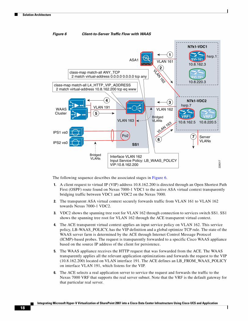
Figure 6 Client-to-Server Traffic Flow with WAAS
The following sequence describes the associated stages in Figure 6.
1. A client request to virtual IP (VIP) address 10.8.162.200 is directed through an Open Shortest Path First (OSPF) route found on Nexus 7000-1 VDC1 to the active ASA virtual context transparently bridging traffic between VDC1 and VDC2 on the Nexus 7000.
2. The transparent ASA virtual context securely forwards traffic from VLAN 161 to VLAN 162 towards Nexus 7000-1 VDC2.
3. VDC2 shows the spanning tree root for VLAN 162 through connection to services switch SS1. SS1 shows the spanning tree root for VLAN 162 through the ACE transparent virtual context.
4. The ACE transparent virtual context applies an input service policy on VLAN 162. This service policy, LB-WAAS_POLICY, has the VIP definition and a global optimize TCP rule. The state of the WAAS server farm is determined by the ACE through Internet Control Message Protocol (ICMP)-based probes. The request is transparently forwarded to a specific Cisco WAAS appliance based on the source IP address of the client for persistence.
5. The WAAS appliance receives the HTTP request that was forwarded from the ACE. The WAAS transparently applies all the relevant application optimizations and forwards the request to the VIP (10.8.162.200) located on VLAN interface 191. The ACE defines an LB_FROM_WAAS_POLICY on interface VLAN 191, which listens for the VIP.
6. The ACE selects a real application server to service the request and forwards the traffic to the Nexus 7000 VRF that supports the real server subnet. Note that the VRF is the default gateway for that particular real server.
ASA1
10.8.220.5
10.8.220.3
10.8.162.3VLAN 161
VLAN 162VLAN 191
VLAN 163VLAN 163
VLAN 162
SS1
N7k1-VDC2
N7k1-VDC1
VRF1
SVI-161
SVI-151
VRF2
10.8.162.5
Po2
2283
17
WAASCluster
1
4
2
6
5
3
ServerVLANs
class-map match-all ANY_TCP 2 match virtual-address 0.0.0.0 0.0.0.0 tcp any
Interface VLAN 162Input Service Policy: LB_WAAS_POLICYVIP:10.8.162.200
IPS1 vs0
IPS2 vs0
7
BridgedVLANs
BridgedVLANs
hsrp.1
hsrp.7
class-map match-all L4_HTTP_VIP_ADDRESS 2 match virtual-address 10.8.162.200 tcp eq www
18Integrating Microsoft Hyper-V Virtualization of SharePoint 2007 into a Cisco Data Center Infrastructure Using Cisco UCS and Application
Solution Architecture
7. The VRF routes the request to the appropriate real server for servicing.
Note Note that the Cisco WAAS solutions and Cisco ACE platforms fully support SSL traffic. In the tested solution, the ACE service module terminated SSL requests while the WAAS appliances in the branch and data center transparently provided application optimization services to the same encrypted traffic.
For more information on integrating Cisco Wide Area Firewall Services (WAFS), Intrusion Prevention System (IPS), or services in general, see “Data Center Service Patterns” at the following URL: http://www.cisco.com/en/US/docs/solutions/Enterprise/Data_Center/DC_3_0/dc_serv_pat.html.
The ACE is a very flexible platform allowing for multiple network services to be seamlessly applied. In addition to the transparent integration of WAAS services previously described, the same ACE virtual context may support remote application optimization services via Cisco WAAS Mobile technology. Cisco WAAS Mobile employs a client-server model where remote agents connect to server or in this example a server supported by the ACE to accelerate the users' experience.
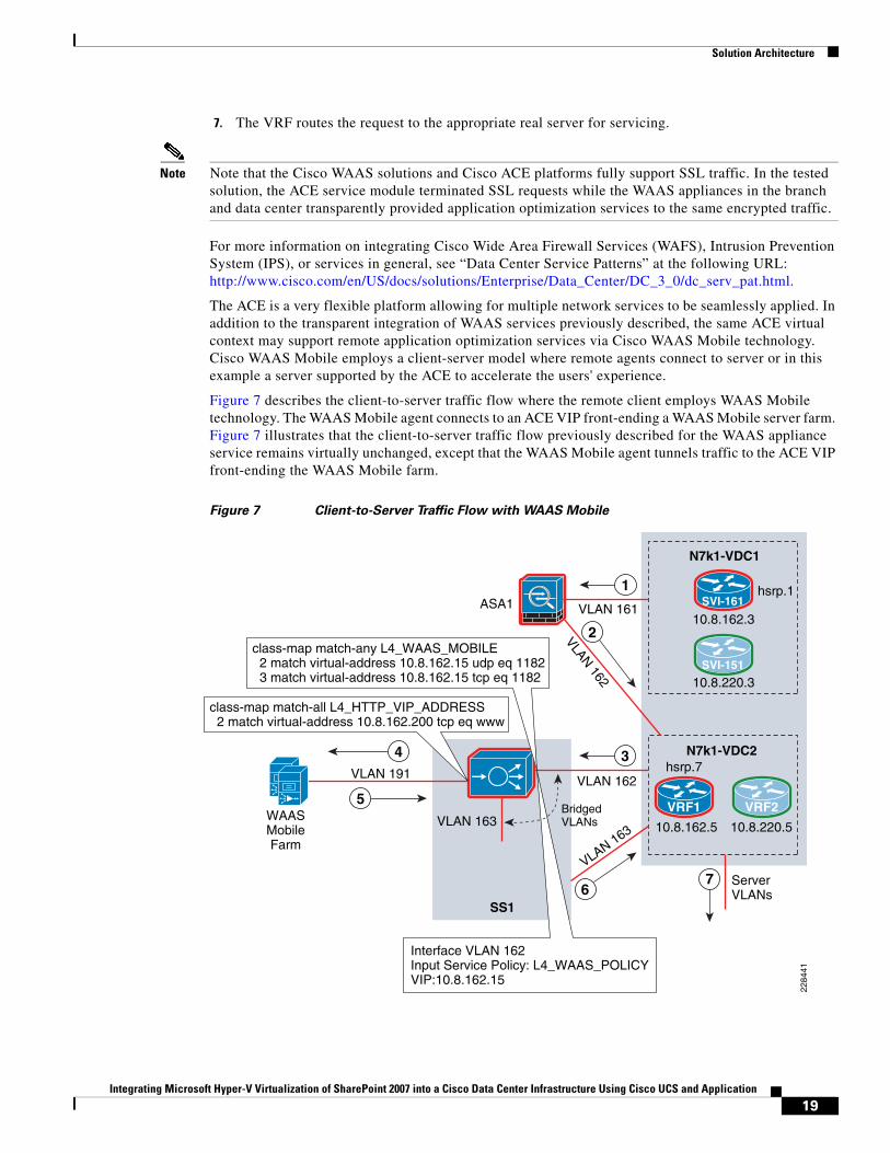
Figure 7 describes the client-to-server traffic flow where the remote client employs WAAS Mobile technology. The WAAS Mobile agent connects to an ACE VIP front-ending a WAAS Mobile server farm. Figure 7 illustrates that the client-to-server traffic flow previously described for the WAAS appliance service remains virtually unchanged, except that the WAAS Mobile agent tunnels traffic to the ACE VIP front-ending the WAAS Mobile farm.
Figure 7 Client-to-Server Traffic Flow with WAAS Mobile
ASA1
10.8.220.5
10.8.220.3
10.8.162.3VLAN 161
VLAN 162VLAN 191
VLAN 163VLAN 163
VLAN 162
SS1
N7k1-VDC2
N7k1-VDC1
VRF1
SVI-161
SVI-151
VRF2
10.8.162.5
2284
41
WAASMobileFarm
1
4
2
6
5
3
ServerVLANs
class-map match-any L4_WAAS_MOBILE 2 match virtual-address 10.8.162.15 udp eq 1182 3 match virtual-address 10.8.162.15 tcp eq 1182
Interface VLAN 162Input Service Policy: L4_WAAS_POLICYVIP:10.8.162.15
7
BridgedVLANs
hsrp.1
hsrp.7
class-map match-all L4_HTTP_VIP_ADDRESS 2 match virtual-address 10.8.162.200 tcp eq www
19Integrating Microsoft Hyper-V Virtualization of SharePoint 2007 into a Cisco Data Center Infrastructure Using Cisco UCS and Application
Solution Architecture
The following describes the flow of traffic passing through the data center by way of WAAS Mobile services:
Step 1 A client request to virtual IP (VIP) address 10.8.162.200, the SharePoint VIP, is proxied by the local WAAS Mobile agent which forwards the request to its previously established WAAS Mobile server, 10.8.162.15. In reality, the 10.8.162.15 address is an ACE VIP. The ACE provides load balancing and scalability services to the WAAS Mobile solution. The connection is directed through an Open Shortest Path First (OSPF) route found on Nexus 7000-1 VDC1 to the active ASA virtual context transparently bridging traffic between VDC1 and VDC2 on the Nexus 7000.
Step 2 The transparent ASA virtual context securely forwards traffic from VLAN 161 to VLAN 162 towards Nexus 7000-1 VDC2.
Step 3 VDC2 shows the spanning tree root for VLAN 162 through connection to services switch SS1. SS1 shows the spanning tree root for VLAN 162 through the ACE transparent virtual context.
Step 4 The ACE transparent virtual context applies an input service policy on VLAN 162. This service policy, LB-WAAS_POLICY, has the VIP definition. The state of the WAAS Mobile server farm is determined by the ACE through TCP based probes on port 1182. The request is transparently forwarded to a specific Cisco WAAS Mobile server based on the source IP address of the client for persistence.
Step 5 The WAAS Mobile server receives the HTTP request that was forwarded from the ACE. The WAAS Mobile applies all the relevant application optimizations and initiates a request to the VIP (10.8.162.200) located on VLAN interface 191. The ACE defines an LB_FROM_WAAS_POLICY on interface VLAN 191, which listens for the VIP.
Step 6 The ACE selects a real application server to service the request and forwards the traffic to the Nexus 7000 VRF that supports the real server subnet. Note that the VRF is the default gateway for that particular real server.
Step 7 The VRF routes the request to the appropriate real server for servicing.
For more details pertaining to the WAAS and WAAS Mobile services implementations, refer to “Appendix A—WAAS Mobile Configuration” section on page 60 and “Appendix B—WAAS Configuration” section on page 65.
Server-to-Server
“Horizontal” or server-to-server traffic must also be addressed in the design. Primarily, this communication is between processes or nodes to support clustering, management, or n-tier applications. The flexibility of the virtual data center design allows you to maintain the integrity of this messaging while simultaneously permitting administrators to select specific horizontal flows for additional services such as access control as well as intrusion detection and/or prevention between the application elements of the access layer.
Intra-VRF
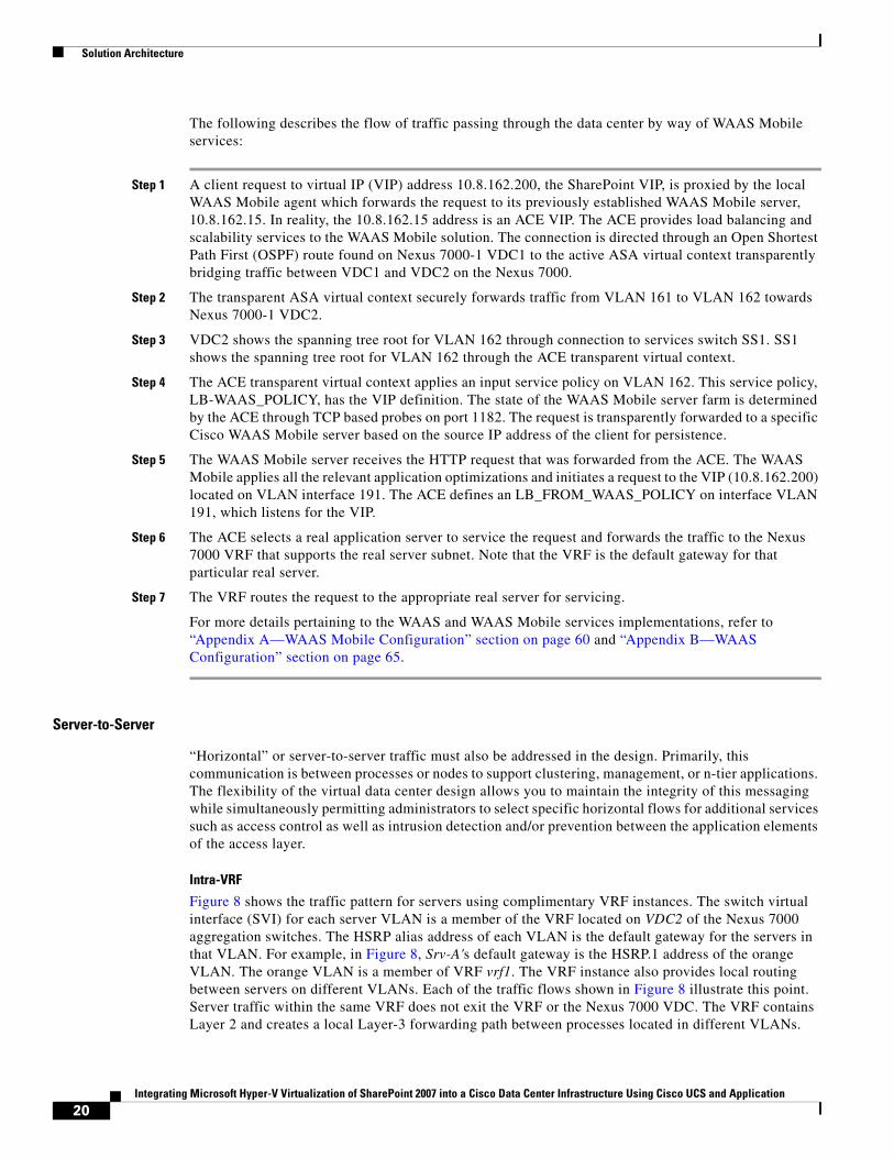
Figure 8 shows the traffic pattern for servers using complimentary VRF instances. The switch virtual interface (SVI) for each server VLAN is a member of the VRF located on VDC2 of the Nexus 7000 aggregation switches. The HSRP alias address of each VLAN is the default gateway for the servers in that VLAN. For example, in Figure 8, Srv-A's default gateway is the HSRP.1 address of the orange VLAN. The orange VLAN is a member of VRF vrf1. The VRF instance also provides local routing between servers on different VLANs. Each of the traffic flows shown in Figure 8 illustrate this point. Server traffic within the same VRF does not exit the VRF or the Nexus 7000 VDC. The VRF contains Layer 2 and creates a local Layer-3 forwarding path between processes located in different VLANs.
20Integrating Microsoft Hyper-V Virtualization of SharePoint 2007 into a Cisco Data Center Infrastructure Using Cisco UCS and Application
Solution Architecture
Figure 8 Intra-VRF Server-to-Server Traffic Pattern in vPC Domain
In addition, the orange and blue VLANs are members of the same vPC domain. This allows for even more efficient traffic flows in the access layer because the vPC peer devices forward traffic directly to its destination without requiring the use of the vPC peer link. In this case, port channel 98, the vPC link, does not carry Flow 4 because the vPC peer device on VDC2 forwards the traffic between Srv-D and Srv-B.
The use of VRFs to contain the Layers 2 and 3 aspects of the network can also be extended to the applications environment. For example, independent application processes that require connectivity but do not require other services such as security or load balancing between them can be logically grouped within the same VRF instance. This concept of a VRF application zone can be extended throughout the enterprise data center to provide segmentation to numerous application environments.
Intra-VRF with Services
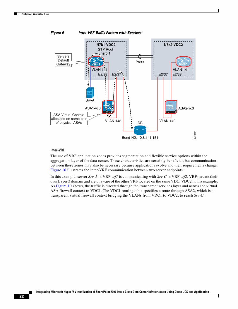
The use of VRF application zones does not exclude the use of network services; in fact, it allows more granular control of those services. For example, Figure 9 shows a VRF application zone where a transparent virtual ASA context is protecting a database instance. The default gateway for the database server is the .1 HSRP address associated with VLAN 141. The 141 SVI is a member of vrf1. Srv-A is an application node using another VLAN that is a member of the same VRF, vrf1. The firewall permits the Srv-A node to connect to the database. The virtual firewall context is not tasked with protecting the whole data center, but a specific server and a specific application. The VRF application zone allows for more specific service rules to be applied, whether security, visibility, scale, or performance-based.
Po99
vPC
Flow 1Flow 2Flow 3Flow 4
N7k1-VDC2 N7k2-VDC2STP Root
hsrp.1
Srv-A
vPCDomain
2283
18Srv-B Srv-C Srv-D
VRF1 VRF1ServersDefault
Gateway
21Integrating Microsoft Hyper-V Virtualization of SharePoint 2007 into a Cisco Data Center Infrastructure Using Cisco UCS and Application
Solution Architecture
Figure 9 Intra-VRF Traffic Pattern with Services
Inter-VRF
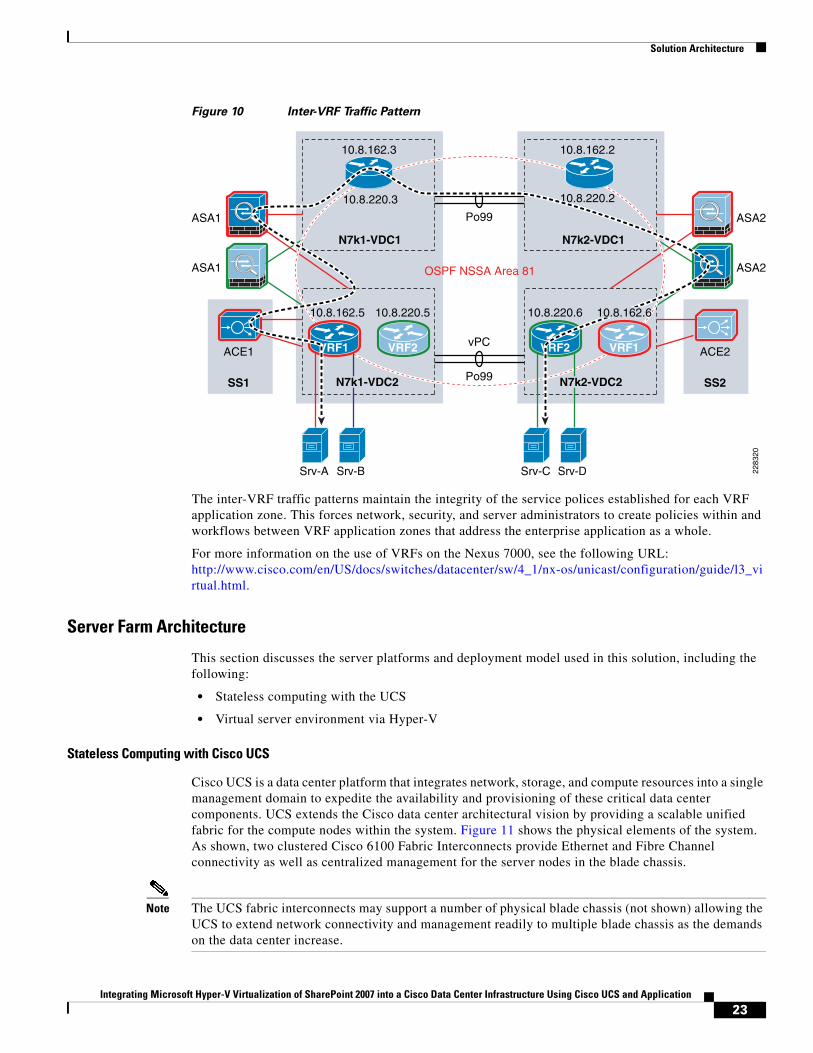
The use of VRF application zones provides segmentation and flexible service options within the aggregation layer of the data center. These characteristics are certainly beneficial, but communication between these zones may also be necessary because applications evolve and their requirements change. Figure 10 illustrates the inter-VRF communication between two server endpoints.
In this example, server Srv-A in VRF vrf1 is communicating with Srv-C in VRF vrf2. VRFs create their own Layer 3 domain and are unaware of the other VRF located on the same VDC, VDC2 in this example. As Figure 10 shows, the traffic is directed through the transparent services layer and across the virtual ASA firewall context to VDC1. The VDC1 routing table specifies a route through ASA2, which is a transparent virtual firewall context bridging the VLANs from VDC1 to VDC2, to reach Srv-C.
Po99
N7k1-VDC2 N7k2-VDC2STP Root
hsrp.1
ASA2-vc3ASA1-vc3
E2/37 E2/38VLAN 141
VLAN 142
Bond142: 10.8.141.151
DBVLAN 142
Srv-A
2283
19
VRF1VRF1
E2/37E2/38VLAN 141
ServersDefault
Gateway
ASA Virtual Contextallocated on same pair
of physical ASAs
22Integrating Microsoft Hyper-V Virtualization of SharePoint 2007 into a Cisco Data Center Infrastructure Using Cisco UCS and Application
Solution Architecture
Figure 10 Inter-VRF Traffic Pattern
The inter-VRF traffic patterns maintain the integrity of the service polices established for each VRF application zone. This forces network, security, and server administrators to create policies within and workflows between VRF application zones that address the enterprise application as a whole.
For more information on the use of VRFs on the Nexus 7000, see the following URL: http://www.cisco.com/en/US/docs/switches/datacenter/sw/4_1/nx-os/unicast/configuration/guide/l3_virtual.html.
Server Farm Architecture
This section discusses the server platforms and deployment model used in this solution, including the following:
• Stateless computing with the UCS
• Virtual server environment via Hyper-V
Stateless Computing with Cisco UCS
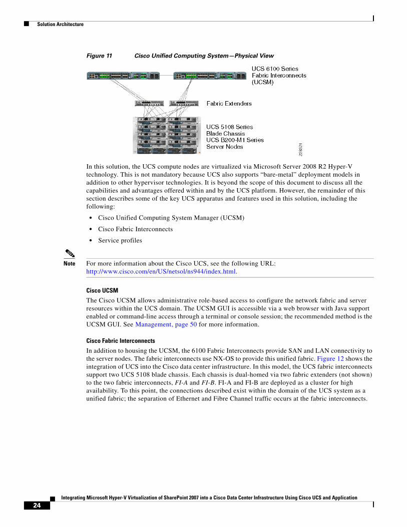
Cisco UCS is a data center platform that integrates network, storage, and compute resources into a single management domain to expedite the availability and provisioning of these critical data center components. UCS extends the Cisco data center architectural vision by providing a scalable unified fabric for the compute nodes within the system. Figure 11 shows the physical elements of the system. As shown, two clustered Cisco 6100 Fabric Interconnects provide Ethernet and Fibre Channel connectivity as well as centralized management for the server nodes in the blade chassis.
Note The UCS fabric interconnects may support a number of physical blade chassis (not shown) allowing the UCS to extend network connectivity and management readily to multiple blade chassis as the demands on the data center increase.
ACE2
ASA2
ASA2
ASA1
Po99
vPC
Po99
10.8.220.610.8.220.5
10.8.220.3 10.8.220.2
10.8.162.3 10.8.162.2
OSPF NSSA Area 81ASA1
ACE1
SS2SS1
N7k1-VDC1 N7k2-VDC1
VRF2 VRF1
10.8.162.5
Srv-A 2283
20
Srv-B Srv-C Srv-D
VRF1 VRF2
N7k1-VDC2 N7k2-VDC2
10.8.162.6
23Integrating Microsoft Hyper-V Virtualization of SharePoint 2007 into a Cisco Data Center Infrastructure Using Cisco UCS and Application
Solution Architecture
Figure 11 Cisco Unified Computing System—Physical View
In this solution, the UCS compute nodes are virtualized via Microsoft Server 2008 R2 Hyper-V technology. This is not mandatory because UCS also supports “bare-metal” deployment models in addition to other hypervisor technologies. It is beyond the scope of this document to discuss all the capabilities and advantages offered within and by the UCS platform. However, the remainder of this section describes some of the key UCS apparatus and features used in this solution, including the following:
• Cisco Unified Computing System Manager (UCSM)
• Cisco Fabric Interconnects
• Service profiles
Note For more information about the Cisco UCS, see the following URL: http://www.cisco.com/en/US/netsol/ns944/index.html.
Cisco UCSM
The Cisco UCSM allows administrative role-based access to configure the network fabric and server resources within the UCS domain. The UCSM GUI is accessible via a web browser with Java support enabled or command-line access through a terminal or console session; the recommended method is the UCSM GUI. See Management, page 50 for more information.
Cisco Fabric Interconnects
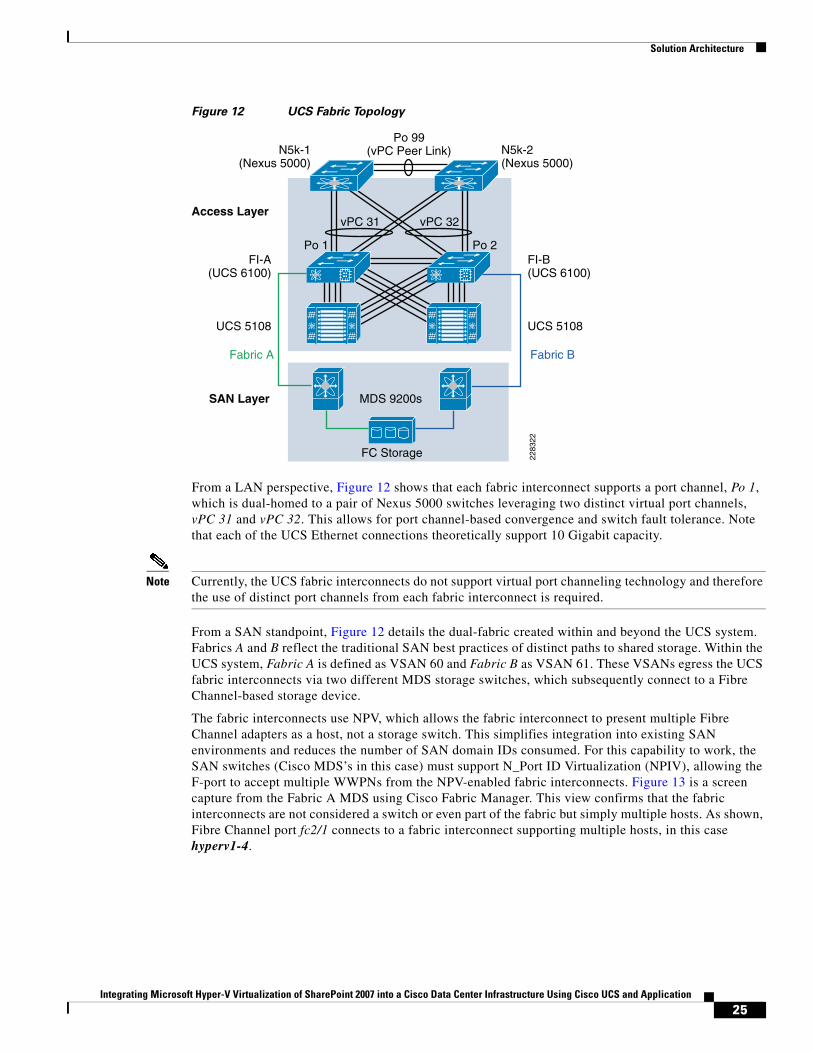
In addition to housing the UCSM, the 6100 Fabric Interconnects provide SAN and LAN connectivity to the server nodes. The fabric interconnects use NX-OS to provide this unified fabric. Figure 12 shows the integration of UCS into the Cisco data center infrastructure. In this model, the UCS fabric interconnects support two UCS 5108 blade chassis. Each chassis is dual-homed via two fabric extenders (not shown) to the two fabric interconnects, FI-A and FI-B. FI-A and FI-B are deployed as a cluster for high availability. To this point, the connections described exist within the domain of the UCS system as a unified fabric; the separation of Ethernet and Fibre Channel traffic occurs at the fabric interconnects.
24Integrating Microsoft Hyper-V Virtualization of SharePoint 2007 into a Cisco Data Center Infrastructure Using Cisco UCS and Application
Solution Architecture
Figure 12 UCS Fabric Topology
From a LAN perspective, Figure 12 shows that each fabric interconnect supports a port channel, Po 1, which is dual-homed to a pair of Nexus 5000 switches leveraging two distinct virtual port channels, vPC 31 and vPC 32. This allows for port channel-based convergence and switch fault tolerance. Note that each of the UCS Ethernet connections theoretically support 10 Gigabit capacity.
Note Currently, the UCS fabric interconnects do not support virtual port channeling technology and therefore the use of distinct port channels from each fabric interconnect is required.
From a SAN standpoint, Figure 12 details the dual-fabric created within and beyond the UCS system. Fabrics A and B reflect the traditional SAN best practices of distinct paths to shared storage. Within the UCS system, Fabric A is defined as VSAN 60 and Fabric B as VSAN 61. These VSANs egress the UCS fabric interconnects via two different MDS storage switches, which subsequently connect to a Fibre Channel-based storage device.
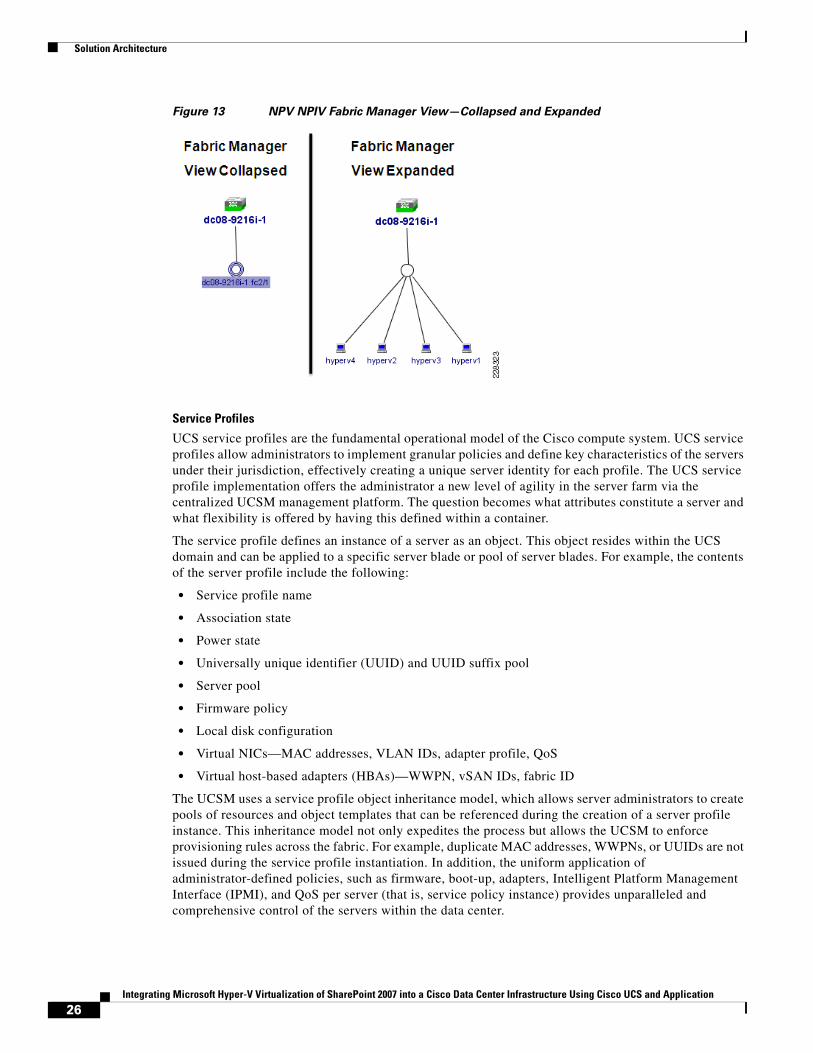
The fabric interconnects use NPV, which allows the fabric interconnect to present multiple Fibre Channel adapters as a host, not a storage switch. This simplifies integration into existing SAN environments and reduces the number of SAN domain IDs consumed. For this capability to work, the SAN switches (Cisco MDS’s in this case) must support N_Port ID Virtualization (NPIV), allowing the F-port to accept multiple WWPNs from the NPV-enabled fabric interconnects. Figure 13 is a screen capture from the Fabric A MDS using Cisco Fabric Manager. This view confirms that the fabric interconnects are not considered a switch or even part of the fabric but simply multiple hosts. As shown, Fibre Channel port fc2/1 connects to a fabric interconnect supporting multiple hosts, in this case hyperv1-4.
Access Layer
SAN Layer MDS 9200s
FC Storage
N5k-1(Nexus 5000)
N5k-2(Nexus 5000)
Po 99(vPC Peer Link)
FI-A(UCS 6100)
UCS 5108
Fabric A
FI-B(UCS 6100)
UCS 5108
Fabric B
Po 1 Po 2
vPC 31 vPC 32
2283
22
25Integrating Microsoft Hyper-V Virtualization of SharePoint 2007 into a Cisco Data Center Infrastructure Using Cisco UCS and Application
Solution Architecture
Figure 13 NPV NPIV Fabric Manager View—Collapsed and Expanded
Service Profiles
UCS service profiles are the fundamental operational model of the Cisco compute system. UCS service profiles allow administrators to implement granular policies and define key characteristics of the servers under their jurisdiction, effectively creating a unique server identity for each profile. The UCS service profile implementation offers the administrator a new level of agility in the server farm via the centralized UCSM management platform. The question becomes what attributes constitute a server and what flexibility is offered by having this defined within a container.
The service profile defines an instance of a server as an object. This object resides within the UCS domain and can be applied to a specific server blade or pool of server blades. For example, the contents of the server profile include the following:
• Service profile name
• Association state
• Power state
• Universally unique identifier (UUID) and UUID suffix pool
• Server pool
• Firmware policy
• Local disk configuration
• Virtual NICs—MAC addresses, VLAN IDs, adapter profile, QoS
• Virtual host-based adapters (HBAs)—WWPN, vSAN IDs, fabric ID
The UCSM uses a service profile object inheritance model, which allows server administrators to create pools of resources and object templates that can be referenced during the creation of a server profile instance. This inheritance model not only expedites the process but allows the UCSM to enforce provisioning rules across the fabric. For example, duplicate MAC addresses, WWPNs, or UUIDs are not issued during the service profile instantiation. In addition, the uniform application of administrator-defined policies, such as firmware, boot-up, adapters, Intelligent Platform Management Interface (IPMI), and QoS per server (that is, service policy instance) provides unparalleled and comprehensive control of the servers within the data center.
26Integrating Microsoft Hyper-V Virtualization of SharePoint 2007 into a Cisco Data Center Infrastructure Using Cisco UCS and Application
Solution Architecture
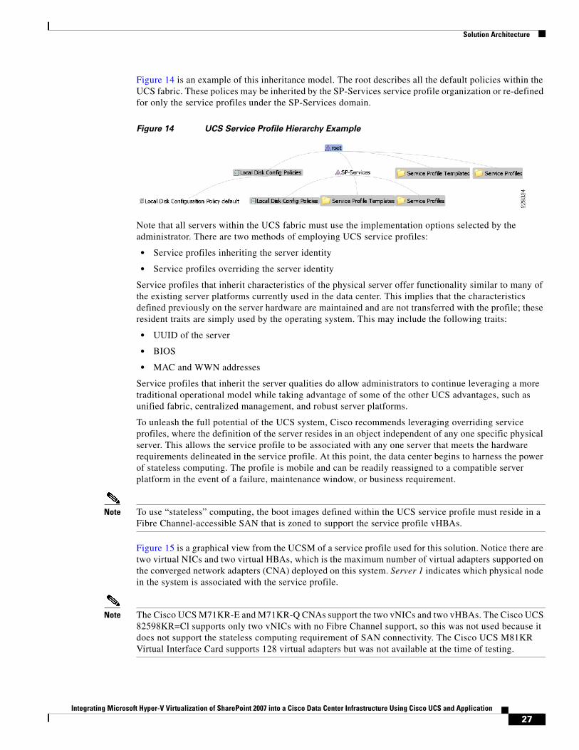
Figure 14 is an example of this inheritance model. The root describes all the default policies within the UCS fabric. These polices may be inherited by the SP-Services service profile organization or re-defined for only the service profiles under the SP-Services domain.
Figure 14 UCS Service Profile Hierarchy Example
Note that all servers within the UCS fabric must use the implementation options selected by the administrator. There are two methods of employing UCS service profiles:
• Service profiles inheriting the server identity
• Service profiles overriding the server identity
Service profiles that inherit characteristics of the physical server offer functionality similar to many of the existing server platforms currently used in the data center. This implies that the characteristics defined previously on the server hardware are maintained and are not transferred with the profile; these resident traits are simply used by the operating system. This may include the following traits:
• UUID of the server
• BIOS
• MAC and WWN addresses
Service profiles that inherit the server qualities do allow administrators to continue leveraging a more traditional operational model while taking advantage of some of the other UCS advantages, such as unified fabric, centralized management, and robust server platforms.
To unleash the full potential of the UCS system, Cisco recommends leveraging overriding service profiles, where the definition of the server resides in an object independent of any one specific physical server. This allows the service profile to be associated with any one server that meets the hardware requirements delineated in the service profile. At this point, the data center begins to harness the power of stateless computing. The profile is mobile and can be readily reassigned to a compatible server platform in the event of a failure, maintenance window, or business requirement.
Note To use “stateless” computing, the boot images defined within the UCS service profile must reside in a Fibre Channel-accessible SAN that is zoned to support the service profile vHBAs.
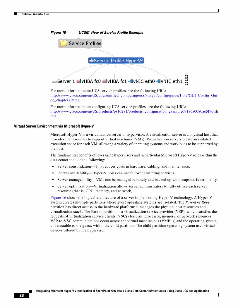
Figure 15 is a graphical view from the UCSM of a service profile used for this solution. Notice there are two virtual NICs and two virtual HBAs, which is the maximum number of virtual adapters supported on the converged network adapters (CNA) deployed on this system. Server 1 indicates which physical node in the system is associated with the service profile.
Note The Cisco UCS M71KR-E and M71KR-Q CNAs support the two vNICs and two vHBAs. The Cisco UCS 82598KR=Cl supports only two vNICs with no Fibre Channel support, so this was not used because it does not support the stateless computing requirement of SAN connectivity. The Cisco UCS M81KR Virtual Interface Card supports 128 virtual adapters but was not available at the time of testing.
27Integrating Microsoft Hyper-V Virtualization of SharePoint 2007 into a Cisco Data Center Infrastructure Using Cisco UCS and Application
Solution Architecture
Figure 15 UCSM View of Service Profile Example
For more information on UCS service profiles, see the following URL: http://www.cisco.com/en/US/docs/unified_computing/ucs/sw/gui/config/guide/1.0.2/GUI_Config_Guide_chapter1.html.
For more information on configuring UCS service profiles, see the following URL: http://www.cisco.com/en/US/products/ps10281/products_configuration_example09186a0080ae5f90.shtml.
Virtual Server Environment via Microsoft Hyper-V
Microsoft Hyper-V is a virtualization server or hypervisor. A virtualization server is a physical host that provides the resources to support virtual machines (VMs). Virtualization servers create an isolated execution space for each VM, allowing a variety of operating systems and workloads to be supported by the host.
The fundamental benefits of leveraging hypervisors and in particular Microsoft Hyper-V roles within the data center include the following:
• Server consolidation—This reduces costs in hardware, cabling, and maintenance.
• Server availability—Hyper-V hosts can use failover clustering services.
• Server manageability—VMs can be managed remotely and backed up with snapshot functionality.
• Server optimization—Virtualization allows server administrators to fully utilize each server resource (that is, CPU, memory, and network).
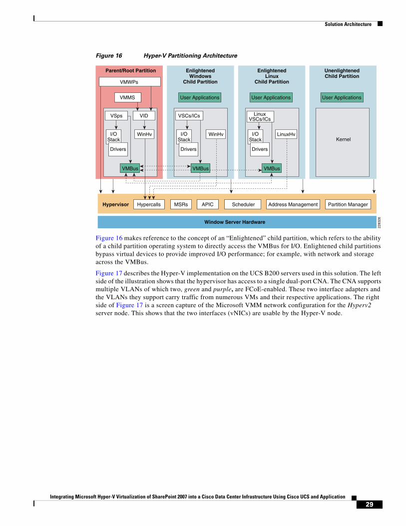
Figure 16 shows the logical architecture of a server implementing Hyper-V technology. A Hyper-V system creates multiple partitions where guest operating systems are isolated. The Parent or Root partition has direct access to the hardware platform; it manages the physical host resources and virtualization stack. The Parent partition is a virtualization service provider (VSP), which satisfies the requests of virtualization service clients (VSCs) for disk, processor, memory, or network resources. VSP-to-VSC communications occur across the virtual machine bus (VMBus) and the operating system, undetectable to the guest, within the child partition. The child partition operating system uses virtual devices offered by the hypervisor.
28Integrating Microsoft Hyper-V Virtualization of SharePoint 2007 into a Cisco Data Center Infrastructure Using Cisco UCS and Application
Solution Architecture
Figure 16 Hyper-V Partitioning Architecture
Figure 16 makes reference to the concept of an “Enlightened” child partition, which refers to the ability of a child partition operating system to directly access the VMBus for I/O. Enlightened child partitions bypass virtual devices to provide improved I/O performance; for example, with network and storage across the VMBus.
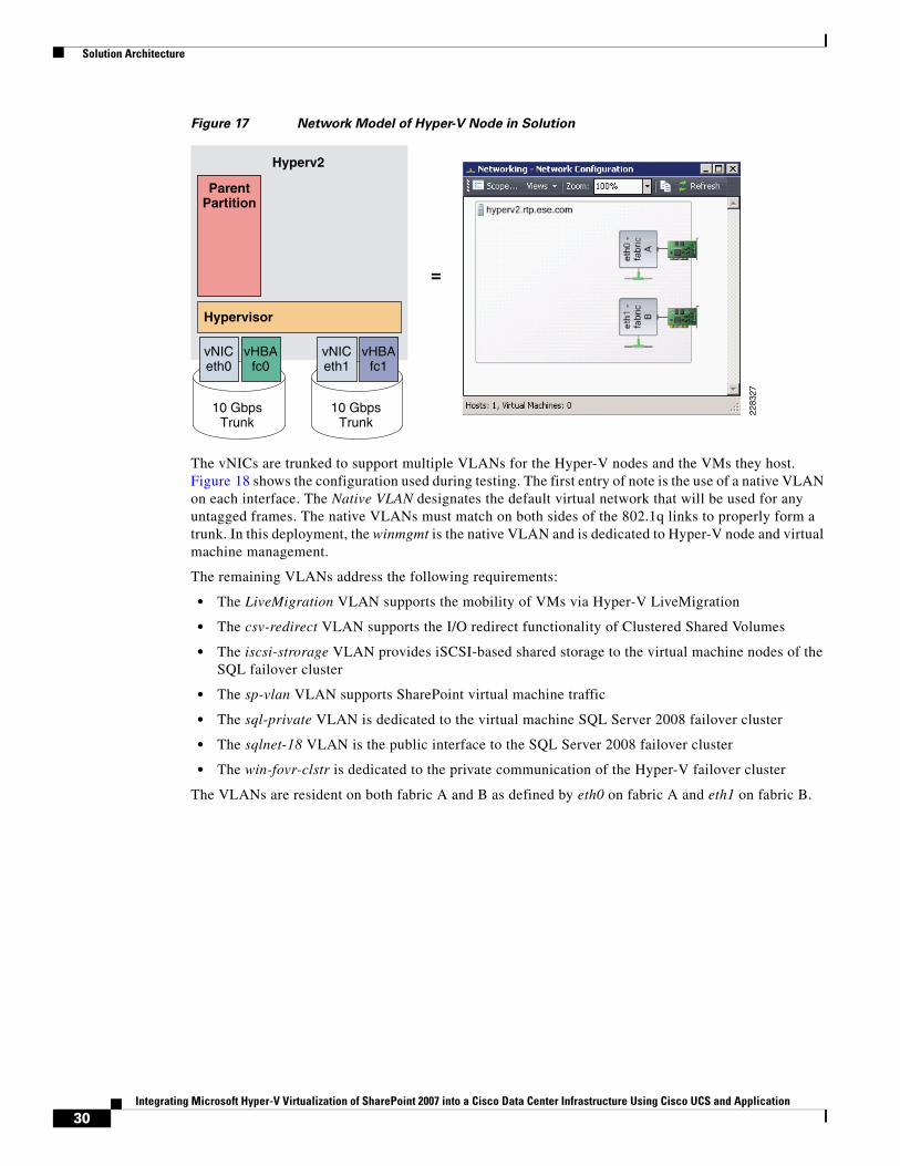
Figure 17 describes the Hyper-V implementation on the UCS B200 servers used in this solution. The left side of the illustration shows that the hypervisor has access to a single dual-port CNA. The CNA supports multiple VLANs of which two, green and purple, are FCoE-enabled. These two interface adapters and the VLANs they support carry traffic from numerous VMs and their respective applications. The right side of Figure 17 is a screen capture of the Microsoft VMM network configuration for the Hyperv2 server node. This shows that the two interfaces (vNICs) are usable by the Hyper-V node.
Parent/Root Partition
VMWPs
HypercallsHypervisor
Window Server Hardware
Scheduler Address Management Partition ManagerMSRs APIC
VMMS
VSps
I/OStack
WinHv
VMBus
Drivers
VID
User Applications
VSCs/ICs
I/OStack
WinHv
Drivers
User Applications User Applications
LinuxVSCs/ICs
I/OStack
LinuxHvKernel
VMBus
Drivers
EnlightenedWindows
Child Partition
EnlightenedLinux
Child Partition
UnenlightenedChild Partition
VMBus
2283
26
29Integrating Microsoft Hyper-V Virtualization of SharePoint 2007 into a Cisco Data Center Infrastructure Using Cisco UCS and Application
Solution Architecture
Figure 17 Network Model of Hyper-V Node in Solution
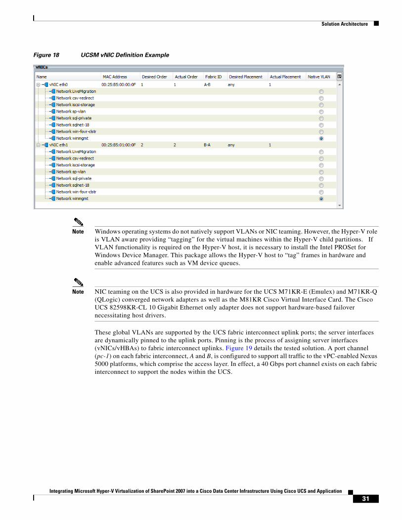
The vNICs are trunked to support multiple VLANs for the Hyper-V nodes and the VMs they host. Figure 18 shows the configuration used during testing. The first entry of note is the use of a native VLAN on each interface. The Native VLAN designates the default virtual network that will be used for any untagged frames. The native VLANs must match on both sides of the 802.1q links to properly form a trunk. In this deployment, the winmgmt is the native VLAN and is dedicated to Hyper-V node and virtual machine management.
The remaining VLANs address the following requirements:
• The LiveMigration VLAN supports the mobility of VMs via Hyper-V LiveMigration
• The csv-redirect VLAN supports the I/O redirect functionality of Clustered Shared Volumes
• The iscsi-strorage VLAN provides iSCSI-based shared storage to the virtual machine nodes of the SQL failover cluster
• The sp-vlan VLAN supports SharePoint virtual machine traffic
• The sql-private VLAN is dedicated to the virtual machine SQL Server 2008 failover cluster
• The sqlnet-18 VLAN is the public interface to the SQL Server 2008 failover cluster
• The win-fovr-clstr is dedicated to the private communication of the Hyper-V failover cluster
The VLANs are resident on both fabric A and B as defined by eth0 on fabric A and eth1 on fabric B.
vNICeth0
vHBAfc0
10 GbpsTrunk
10 GbpsTrunk
2283
27
ParentPartition
Hyperv2
Hypervisor
vNICeth1
vHBAfc1
=
30Integrating Microsoft Hyper-V Virtualization of SharePoint 2007 into a Cisco Data Center Infrastructure Using Cisco UCS and Application
Solution Architecture
Figure 18 UCSM vNIC Definition Example
Note Windows operating systems do not natively support VLANs or NIC teaming. However, the Hyper-V role is VLAN aware providing “tagging” for the virtual machines within the Hyper-V child partitions. If VLAN functionality is required on the Hyper-V host, it is necessary to install the Intel PROSet for Windows Device Manager. This package allows the Hyper-V host to “tag” frames in hardware and enable advanced features such as VM device queues.
Note NIC teaming on the UCS is also provided in hardware for the UCS M71KR-E (Emulex) and M71KR-Q (QLogic) converged network adapters as well as the M81KR Cisco Virtual Interface Card. The Cisco UCS 82598KR-CL 10 Gigabit Ethernet only adapter does not support hardware-based failover necessitating host drivers.
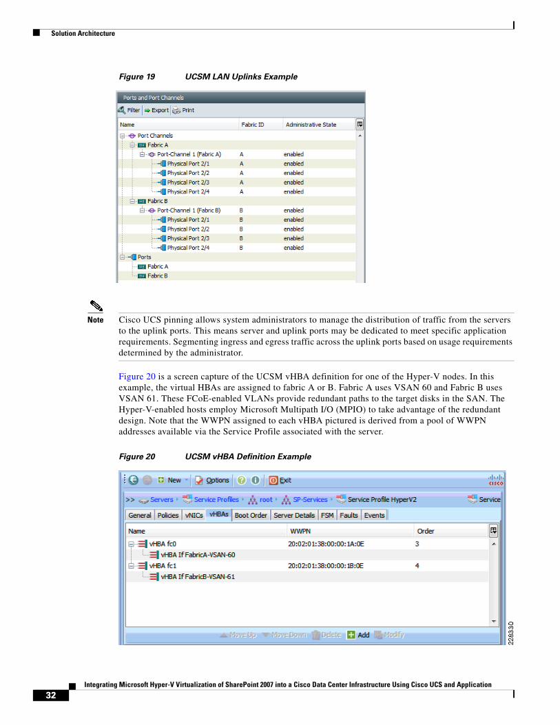
These global VLANs are supported by the UCS fabric interconnect uplink ports; the server interfaces are dynamically pinned to the uplink ports. Pinning is the process of assigning server interfaces (vNICs/vHBAs) to fabric interconnect uplinks. Figure 19 details the tested solution. A port channel (pc-1) on each fabric interconnect, A and B, is configured to support all traffic to the vPC-enabled Nexus 5000 platforms, which comprise the access layer. In effect, a 40 Gbps port channel exists on each fabric interconnect to support the nodes within the UCS.
31Integrating Microsoft Hyper-V Virtualization of SharePoint 2007 into a Cisco Data Center Infrastructure Using Cisco UCS and Application
Solution Architecture
Figure 19 UCSM LAN Uplinks Example
Note Cisco UCS pinning allows system administrators to manage the distribution of traffic from the servers to the uplink ports. This means server and uplink ports may be dedicated to meet specific application requirements. Segmenting ingress and egress traffic across the uplink ports based on usage requirements determined by the administrator.
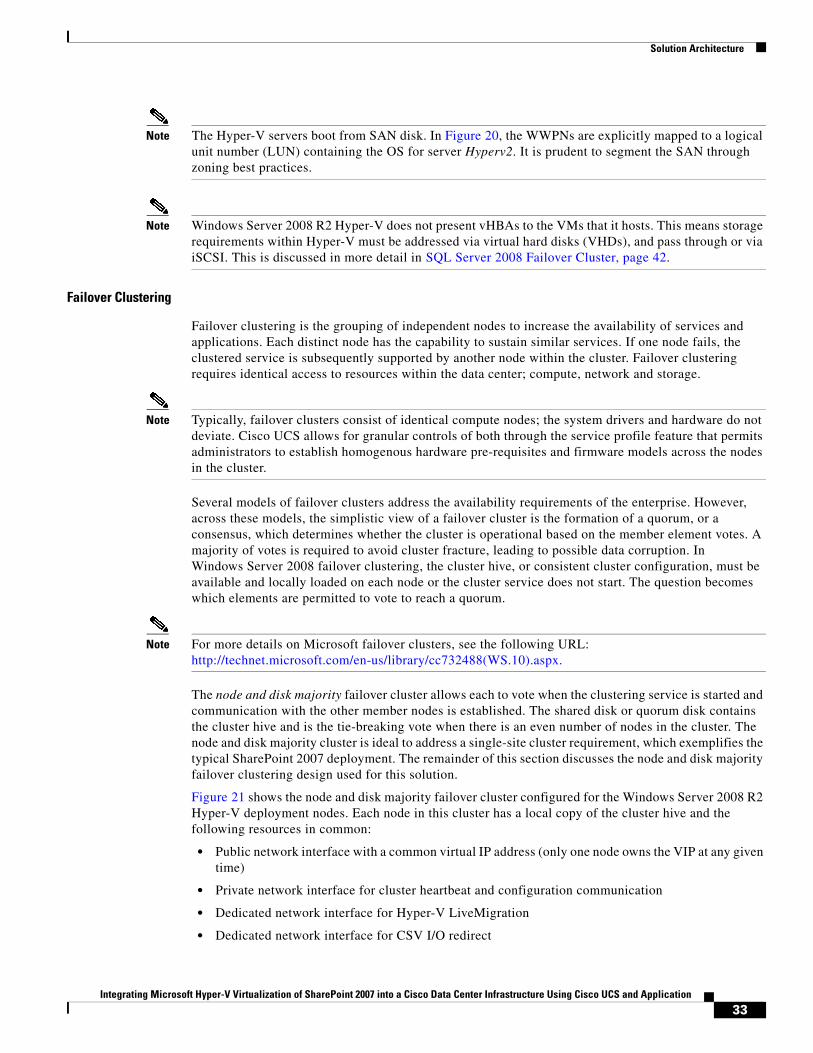
Figure 20 is a screen capture of the UCSM vHBA definition for one of the Hyper-V nodes. In this example, the virtual HBAs are assigned to fabric A or B. Fabric A uses VSAN 60 and Fabric B uses VSAN 61. These FCoE-enabled VLANs provide redundant paths to the target disks in the SAN. The Hyper-V-enabled hosts employ Microsoft Multipath I/O (MPIO) to take advantage of the redundant design. Note that the WWPN assigned to each vHBA pictured is derived from a pool of WWPN addresses available via the Service Profile associated with the server.
Figure 20 UCSM vHBA Definition Example
32Integrating Microsoft Hyper-V Virtualization of SharePoint 2007 into a Cisco Data Center Infrastructure Using Cisco UCS and Application
Solution Architecture
Note The Hyper-V servers boot from SAN disk. In Figure 20, the WWPNs are explicitly mapped to a logical unit number (LUN) containing the OS for server Hyperv2. It is prudent to segment the SAN through zoning best practices.
Note Windows Server 2008 R2 Hyper-V does not present vHBAs to the VMs that it hosts. This means storage requirements within Hyper-V must be addressed via virtual hard disks (VHDs), and pass through or via iSCSI. This is discussed in more detail in SQL Server 2008 Failover Cluster, page 42.
Failover Clustering
Failover clustering is the grouping of independent nodes to increase the availability of services and applications. Each distinct node has the capability to sustain similar services. If one node fails, the clustered service is subsequently supported by another node within the cluster. Failover clustering requires identical access to resources within the data center; compute, network and storage.
Note Typically, failover clusters consist of identical compute nodes; the system drivers and hardware do not deviate. Cisco UCS allows for granular controls of both through the service profile feature that permits administrators to establish homogenous hardware pre-requisites and firmware models across the nodes in the cluster.
Several models of failover clusters address the availability requirements of the enterprise. However, across these models, the simplistic view of a failover cluster is the formation of a quorum, or a consensus, which determines whether the cluster is operational based on the member element votes. A majority of votes is required to avoid cluster fracture, leading to possible data corruption. In Windows Server 2008 failover clustering, the cluster hive, or consistent cluster configuration, must be available and locally loaded on each node or the cluster service does not start. The question becomes which elements are permitted to vote to reach a quorum.
Note For more details on Microsoft failover clusters, see the following URL: http://technet.microsoft.com/en-us/library/cc732488(WS.10).aspx.
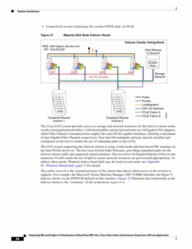
The node and disk majority failover cluster allows each to vote when the clustering service is started and communication with the other member nodes is established. The shared disk or quorum disk contains the cluster hive and is the tie-breaking vote when there is an even number of nodes in the cluster. The node and disk majority cluster is ideal to address a single-site cluster requirement, which exemplifies the typical SharePoint 2007 deployment. The remainder of this section discusses the node and disk majority failover clustering design used for this solution.
Figure 21 shows the node and disk majority failover cluster configured for the Windows Server 2008 R2 Hyper-V deployment nodes. Each node in this cluster has a local copy of the cluster hive and the following resources in common:
• Public network interface with a common virtual IP address (only one node owns the VIP at any given time)
• Private network interface for cluster heartbeat and configuration communication
• Dedicated network interface for Hyper-V LiveMigration
• Dedicated network interface for CSV I/O redirect
33Integrating Microsoft Hyper-V Virtualization of SharePoint 2007 into a Cisco Data Center Infrastructure Using Cisco UCS and Application
Solution Architecture
• Connectivity to new technology file system (NTFS) disk via FCoE
Figure 21 Majority Disk Node Failover Cluster
The Cisco UCS system provides access to storage and network resources for the failover cluster nodes via the converged network fabric. LAN-based public and private networks use 10 Gigabit CNA adapters, while Fibre Channel communications employ the same FCoE-capable interfaces, allowing a maximum of four Gigabit Fibre Channel connectivity. Note that I/O multipath software must be installed and configured on the host to enable the use of redundant paths to the LUNs.
The UCS system supporting this failover cluster is using switch mode and host-based NIC teaming via the Intel ProSet driver set. The host uses Switch Fault Tolerance, providing redundant paths for the failover cluster traffic and supported virtual machines. The use of two 10-Gigabit Etherner CNAs for the numerous VLANs needs the use of QoS to assure network resources are provisioned appropriately. To address these needs, Windows policy-based QoS may be used on each node; see Appendix D—Windows-Based QoS, page 71 for details.
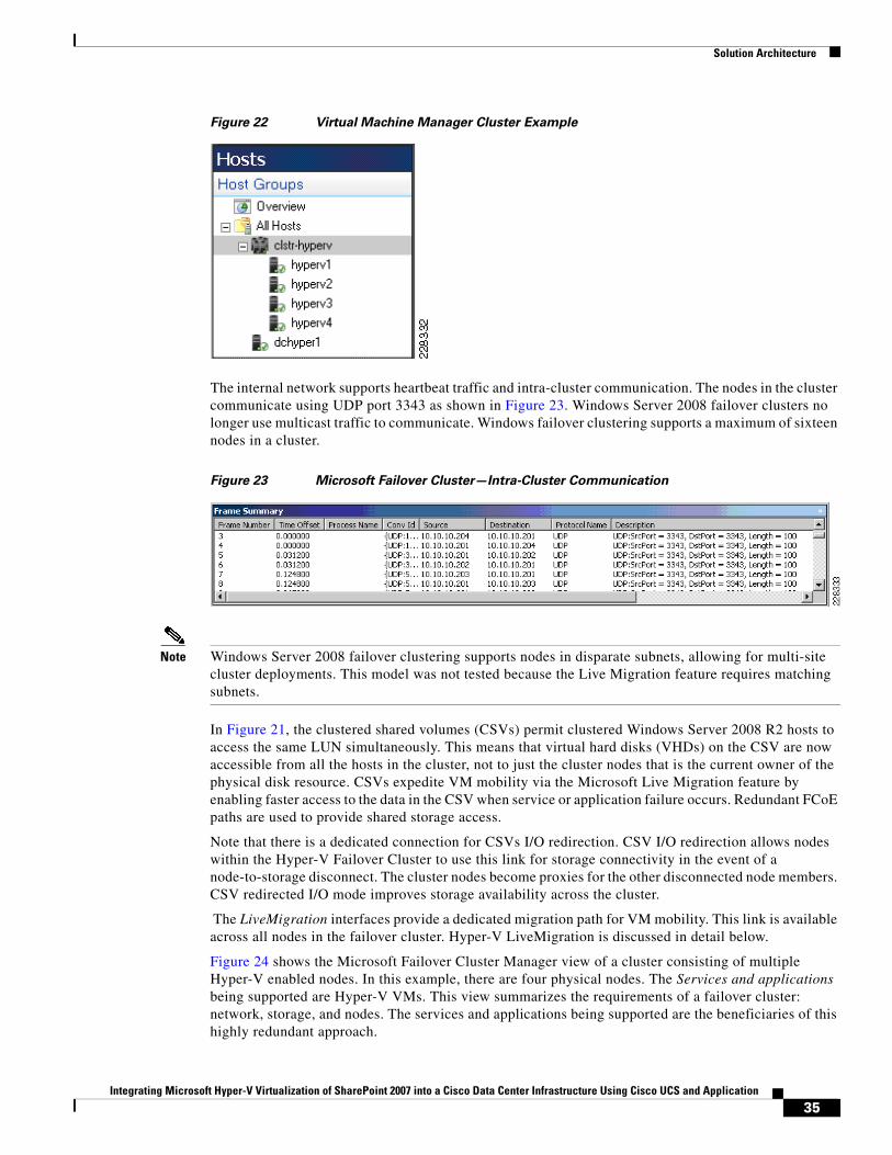
The public network is the external presence of the cluster that allows client access to the services it supports. For example, the Microsoft Virtual Machine Manager 2007 (VMM) identifies the Hyper-V failover cluster via the DNS/VIP defined on this interface. Figure 22 illustrates this relationship as the failover cluster is the “container” of the actual hosts, hyperv1-4.
Clustered SharedVolume 2
Clustered SharedVolume 1
.VHD.VHD.VHD.VHD.VHD.VHD.VHD
.VHD.VHD.VHD.VHD.VHD.VHD.VHD
Failover Cluster Voting Block
Disk Witnessin Quorum
StorageNetwork
DNS: clstr-hyperv.rtp.ese.com VIP: 10.8.20.200
(10.10.10.x/24)
.201 .202 .203 .204
ClusterHive
2283
31
PublicPrivateLiveMigrationCSV I/O RedirectFCoE Fabric AFCoE Fabric B
34Integrating Microsoft Hyper-V Virtualization of SharePoint 2007 into a Cisco Data Center Infrastructure Using Cisco UCS and Application
Solution Architecture
Figure 22 Virtual Machine Manager Cluster Example
The internal network supports heartbeat traffic and intra-cluster communication. The nodes in the cluster communicate using UDP port 3343 as shown in Figure 23. Windows Server 2008 failover clusters no longer use multicast traffic to communicate. Windows failover clustering supports a maximum of sixteen nodes in a cluster.
Figure 23 Microsoft Failover Cluster—Intra-Cluster Communication
Note Windows Server 2008 failover clustering supports nodes in disparate subnets, allowing for multi-site cluster deployments. This model was not tested because the Live Migration feature requires matching subnets.
In Figure 21, the clustered shared volumes (CSVs) permit clustered Windows Server 2008 R2 hosts to access the same LUN simultaneously. This means that virtual hard disks (VHDs) on the CSV are now accessible from all the hosts in the cluster, not to just the cluster nodes that is the current owner of the physical disk resource. CSVs expedite VM mobility via the Microsoft Live Migration feature by enabling faster access to the data in the CSV when service or application failure occurs. Redundant FCoE paths are used to provide shared storage access.
Note that there is a dedicated connection for CSVs I/O redirection. CSV I/O redirection allows nodes within the Hyper-V Failover Cluster to use this link for storage connectivity in the event of a node-to-storage disconnect. The cluster nodes become proxies for the other disconnected node members. CSV redirected I/O mode improves storage availability across the cluster.
The LiveMigration interfaces provide a dedicated migration path for VM mobility. This link is available across all nodes in the failover cluster. Hyper-V LiveMigration is discussed in detail below.
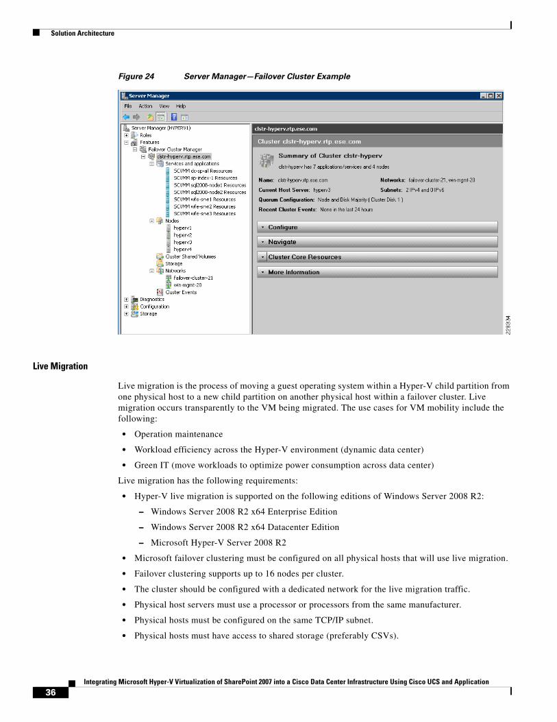
Figure 24 shows the Microsoft Failover Cluster Manager view of a cluster consisting of multiple Hyper-V enabled nodes. In this example, there are four physical nodes. The Services and applications being supported are Hyper-V VMs. This view summarizes the requirements of a failover cluster: network, storage, and nodes. The services and applications being supported are the beneficiaries of this highly redundant approach.
35Integrating Microsoft Hyper-V Virtualization of SharePoint 2007 into a Cisco Data Center Infrastructure Using Cisco UCS and Application
Solution Architecture
Figure 24 Server Manager—Failover Cluster Example
Live Migration
Live migration is the process of moving a guest operating system within a Hyper-V child partition from one physical host to a new child partition on another physical host within a failover cluster. Live migration occurs transparently to the VM being migrated. The use cases for VM mobility include the following:
• Operation maintenance
• Workload efficiency across the Hyper-V environment (dynamic data center)
• Green IT (move workloads to optimize power consumption across data center)
Live migration has the following requirements:
• Hyper-V live migration is supported on the following editions of Windows Server 2008 R2:
– Windows Server 2008 R2 x64 Enterprise Edition
– Windows Server 2008 R2 x64 Datacenter Edition
– Microsoft Hyper-V Server 2008 R2
• Microsoft failover clustering must be configured on all physical hosts that will use live migration.
• Failover clustering supports up to 16 nodes per cluster.
• The cluster should be configured with a dedicated network for the live migration traffic.
• Physical host servers must use a processor or processors from the same manufacturer.
• Physical hosts must be configured on the same TCP/IP subnet.
• Physical hosts must have access to shared storage (preferably CSVs).
36Integrating Microsoft Hyper-V Virtualization of SharePoint 2007 into a Cisco Data Center Infrastructure Using Cisco UCS and Application
Solution Architecture
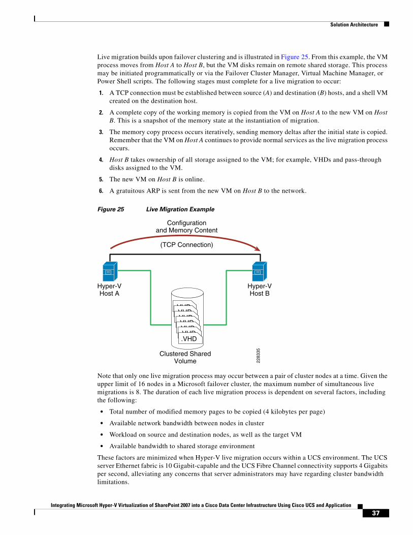
Live migration builds upon failover clustering and is illustrated in Figure 25. From this example, the VM process moves from Host A to Host B, but the VM disks remain on remote shared storage. This process may be initiated programmatically or via the Failover Cluster Manager, Virtual Machine Manager, or Power Shell scripts. The following stages must complete for a live migration to occur:
1. A TCP connection must be established between source (A) and destination (B) hosts, and a shell VM created on the destination host.
2. A complete copy of the working memory is copied from the VM on Host A to the new VM on Host B. This is a snapshot of the memory state at the instantiation of migration.
3. The memory copy process occurs iteratively, sending memory deltas after the initial state is copied. Remember that the VM on Host A continues to provide normal services as the live migration process occurs.
4. Host B takes ownership of all storage assigned to the VM; for example, VHDs and pass-through disks assigned to the VM.
5. The new VM on Host B is online.
6. A gratuitous ARP is sent from the new VM on Host B to the network.
Figure 25 Live Migration Example
Note that only one live migration process may occur between a pair of cluster nodes at a time. Given the upper limit of 16 nodes in a Microsoft failover cluster, the maximum number of simultaneous live migrations is 8. The duration of each live migration process is dependent on several factors, including the following:
• Total number of modified memory pages to be copied (4 kilobytes per page)
• Available network bandwidth between nodes in cluster
• Workload on source and destination nodes, as well as the target VM
• Available bandwidth to shared storage environment
These factors are minimized when Hyper-V live migration occurs within a UCS environment. The UCS server Ethernet fabric is 10 Gigabit-capable and the UCS Fibre Channel connectivity supports 4 Gigabits per second, alleviating any concerns that server administrators may have regarding cluster bandwidth limitations.
Hyper-VHost B
Hyper-VHost A
2283
35Clustered SharedVolume
(TCP Connection)
Configurationand Memory Content
.VHD.VHD.VHD.VHD.VHD.VHD.VHD
37Integrating Microsoft Hyper-V Virtualization of SharePoint 2007 into a Cisco Data Center Infrastructure Using Cisco UCS and Application
Solution Architecture
For more information on Hyper-V Live Migration, see the following URL: http://www.microsoft.com/downloads/details.aspx?FamilyID=fdd083c6-3fc7-470b-8569-7e6a19fb0fdf&displaylang=en.
Application Architecture
This section discusses the deployment of the following Microsoft technologies:
• Office SharePoint 2007 Server Farm
• SQL Server 2008 Failover Cluster
Each of these application environments are deployed within a Microsoft Hyper-V Failover Cluster. The Hyper-V cluster nodes themselves are leveraging a “stateless” compute model via the Cisco UCS service profile. (See Service Profiles, page 26.) This model allows for improved availability and flexibility of the server farm with server mobility and extensible application provisioning.
Office SharePoint 2007 Server Farm
Microsoft Office SharePoint 2007 is a tool that addresses many business drivers in the modern enterprise, including the following:
• Portal or web presence with built-in flexibility, security, and functionality; for example, search
• Document management
• Collaboration across the enterprise and its partners
The inherent flexibility of the SharePoint platform allows enterprises to readily create a custom environment on a well-structured set of services. SharePoint services may be employed on a single server platform or across any number of servers (physical or virtual) to address redundancy, resiliency, and scalability concerns. The division of duties aligns with the concept of roles.
In SharePoint, the following five primary roles must be addressed for a complete solution:
• Web
• Query
• Indexing
• Excel calculation server (application server)
• Database
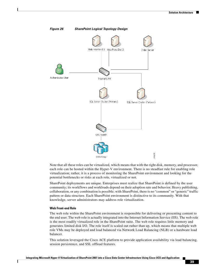
Figure 26 shows the output of the Microsoft SharePoint Capacity Planning Tool. This tool allows you to enter user population and server characteristics to create a baseline environment to meet the SharePoint business objectives of the enterprise. This topology is the baseline for the solution under test and can be characterized as a collaborative SharePoint 2007 site with approximately one thousand users.
38Integrating Microsoft Hyper-V Virtualization of SharePoint 2007 into a Cisco Data Center Infrastructure Using Cisco UCS and Application
Solution Architecture
Figure 26 SharePoint Logical Topology Design
Note that all these roles can be virtualized, which means that with the right disk, memory, and processor, each role can be hosted within the Hyper-V environment. There is no steadfast rule for enabling role virtualization; rather, it is a process of monitoring the SharePoint environment and looking for the potential bottlenecks or risks at each role, virtualized or not.
SharePoint deployments are unique. Enterprises must realize that SharePoint is defined by the user community; its workflows and workloads depend on their adoption rate and behavior. Heavy publishing, collaboration, or any combination is possible; with SharePoint, there is no “common” or “generic” traffic pattern or data structure. Each SharePoint environment is distinctive to its community. With that knowledge, server administrators may address role virtualization.
Web Front-end Role
The web role within the SharePoint environment is responsible for delivering or presenting content to the end user. The web role is actually integrated into the Internet Information Service (IIS). The web role is the most readily virtualized role in the SharePoint suite. The web role requires little memory and generates limited disk I/O. The role itself is scaled out rather than up, which means that multiple web role VMs may be deployed and load balanced via Network Load Balancing (NLB) or a hardware load balancer.
This solution leveraged the Cisco ACE platform to provide application availability via load balancing, session persistence, and SSL offload features.
39Integrating Microsoft Hyper-V Virtualization of SharePoint 2007 into a Cisco Data Center Infrastructure Using Cisco UCS and Application
Solution Architecture
Query Role
The query role provides results for end-user searches. Each query server hosts a local copy of the site index, which means query servers have increased disk requirements. These requirements vary based on the amount of content to be indexed. There are the following three deployment models for the query role:
• Combined web and query role server
• Dedicated query role server
• Combined index and query role server
Traditionally, SharePoint administrators have combined the web and query roles on a single physical server. This approach increases the disk requirement for the server platform because each query role contains a local copy of the index provided by the index server role. This approach remains valid in a Hyper-V environment as well, where VHDs or dedicated physical LUNs are made available to the query role. However, with Hyper-V, this role may be easily designated to dedicated VMs with their own dedicated disks, separating the web and query role across VMs. Virtualization affords this flexibility.
The final option is to combine the index and query roles, where a single VM provides both services. This removes the increased disk requirements across the web roles because the index data is retained on the merged index query server. The index information resides on one server, a single point of failure. This simplifies the deployment but may require more dedicated resources to the VM to maintain acceptable performance. This of course depends on the size of the index corpus and user behavior. Availability of these roles on a single platform relies on live migration and snapshots of this VM and associated content.
For further discussion of VHD and direct access disks, refer to SQL Server 2008 Failover Cluster, page 42.
Index Role
The index role crawls SharePoint Shared Services Providers (SSPs) content and builds an associated index for the SSP. Each SSP has a single index role associated with it; however, a single index role may support multiple SSPs. The index corpus may be used locally on an index server that simultaneously satisfies the query and index server role.
Note Combining index and query roles on the same server platform is not recommended because scale and availability issues are more probable.
Thus far, the index server role appears to be a single point of failure in the SharePoint application design, but this is not the case. Remember that the index corpus is distributed to all servers fulfilling the query role for the associated SSP. This distribution model creates redundant copies of the SSP index data across the query role servers, providing redundancy at the index corpus level.
Consider the following options when determining the SharePoint index role design:
• Employ multiple query role servers to provide redundant index corpus copies and query scalability.
• Distribute SSP index corpus responsibilities across multiple index roles to scale the environment.
• Virtualize the index role per SSP provisioning each virtual index machine according to the need of the SSP.
The first two bullets have been discussed and are self-explanatory, but the third option requires some discussion. The flexibility of VMs allows SharePoint administrators to create an index role per SSP. This distributes index processing on a per-SSP basis, alleviating potential bottlenecks. This requires coordination between the SharePoint site designers and server administrators because of the interdependency created between site content and server deployment.
40Integrating Microsoft Hyper-V Virtualization of SharePoint 2007 into a Cisco Data Center Infrastructure Using Cisco UCS and Application
Solution Architecture
Excel Calculation Services Role
The Excel Calculation Services system requirements are closely aligned with the web front-end server role described earlier. This alignment leads to the natural combination of the web and Excel roles on the same server. Depending on the enterprises traffic profile, the separation of these duties may be necessary, again the flexibility afforded via virtualization will readily accommodate the user demand.
Note It is important to note the increased memory requirement for the ECS role. The role uses up to 50 percent of the available memory to the Excel Calculation Services; hence the recommended amount of RAM for the role is doubled. The ECS stores active and inactive Excel objects in memory. The Cisco UCS with its raw DIMM capacity becomes an interesting option for this service offering.
Database Role
The database role is the custodian of all SharePoint content, and thus the foundation of the application. Therefore, the performance of the database role is critical to the performance of the SharePoint environment. The database relies on the I/O capabilities of its host to meet SharePoint content demands. Disk I/O is typically the source of poorly performing SharePoint applications, but all these factors may impede the application.
The general rule for the database role to meet the demands of SharePoint is to scale out and up, and provide more CPU, memory, and I/O capacity within a cluster. Clustering the database role provides for redundancy and rapid convergence of the environment; clustering nodes that address the aforementioned performance barriers is ideal. General physical recommendations pertaining to the use of SQL Server 2008 with Office SharePoint 2007 include the following:
• L2 cache with 2 MB minimum
• 16 GB of RAM minimum
• Fabric latency between database role and other roles ~1 millisecond
• Limit database to 100 GB
In addition to the physical attributes suggested for the database role, the SharePoint design itself impacts the performance of the database. The following practices may help avoid the database becoming a bottleneck to the application:
• Use DB connection aliases for potential database migrations
• Create multiple SharePoint sites, distributed across multiple database instances
• Use subfolders within SharePoint lists to reduce database blocking
• Enable the front-end server cache to reduce database activity
• Dedicate a disk to read or read/write (RAID 10 suggested) functionality
Note A discussion of Office SharePoint site design is well beyond the scope of this document. However, note that the interdependencies between compute, storage, network, and application run deep, requiring the owners of each to work together toward a truly successful implementation.
Historically, virtualization of the database role has been relegated to test and smaller production environments, but given the performance advancements in Hyper-V and the UCS server platform, server administrators may want the flexibility afforded via a virtual environment. The following section discusses the virtual SQL Server 2008 Failover Cluster environment employed for this solution in detail. The key to creating a robust SharePoint environment is to monitor the processor utilization patterns, RAM usage, and logs across all of the roles, regardless of the physical or virtual nature of the server.
41Integrating Microsoft Hyper-V Virtualization of SharePoint 2007 into a Cisco Data Center Infrastructure Using Cisco UCS and Application
Solution Architecture
Note For more information on SharePoint Server 2007 hardware and software requirements, see the following URL: http://technet.microsoft.com/en-us/library/cc262485.aspx.
Note For more information on VMs and SharePoint roles, see the “Virtualization of SharePoint Products and Technologies White Paper” at the following URL: http://download.microsoft.com/download/1/6/f/16f53b33-a118-4d78-a3d8-653a139aec0e/Virtualization_of_SharePoint_Products_and_Technologies_White_Paper_-_final1%20(2).pdf.
SQL Server 2008 Failover Cluster
The SQL Server 2008 Failover Cluster fulfills the database role in the SharePoint 2007 enterprise deployment model. The database contains all of the data for the SharePoint environment, including the following:
• Documents
• Lists
• Web elements
• Content
The data is the centerpiece of the SharePoint solution; therefore, it must be readily available to the other SharePoint roles previously defined. Traditionally, dedicated physical hosts are clustered to form the SQL cluster. However, given the advances in the Microsoft Hyper-V virtualization platform and the performance capabilities of Cisco UCS, the SQL 2008 failover cluster was hosted within virtual nodes.
The Hyper-V failover cluster contains two VMs whose VHDs reside on the clustered shared volumes (CSVs) as described in Failover Clustering, page 33 and illustrated in Figure 21. Each of these SQL 2008 VM nodes immediately benefits from the redundancy and live migration features of the failover cluster. Nonetheless, to form a proper SQL cluster, the VM SQL nodes must form a failover cluster between themselves, which is essentially a SQL failover cluster within a Hyper-V failover cluster. As previously described, a cluster requires shared network and storage resources, even within a VM environment. The question becomes how to provide or present these resources to the VM nodes.
The following subsections discuss three methods to introduce storage to the Hyper-V virtual machines.
Pass-Through Disks
Pass-through disks are LUNs exposed to the VM directly. Although this model provides excellent I/O performance because of the synthetic SCSI Hyper-V controller, it does have some caveats. Pass-through disks are not mounted by the Hyper-V host but simply exposed by it. The pass-through disk becomes a “Reserved” resource of the Hyper-V failover cluster and a dependency for the VM. The VM must mount and unmount this resource, which means that the disk is not accessible by any other node. This prohibits the implementation of a VM-based SQL failover cluster, because only a single VM may use the disk at any given time.
The pass-through disk method works for a single SQL VM, but was not employed for this solution. The pass-through approach, however, should not be dismissed entirely because live migration allows a single SQL node to migrate and remain available across the Hyper-V cluster. Remember that the pass-through disk is a dependent resource as defined by the Hyper-V failover cluster; it migrates with the VM but there may be an interruption in services because the VM must allow the pass-through disk to unmount from the source Hyper-V host and remount at the destination Hyper-V host. This process may impact application performance depending on the disks presence.
42Integrating Microsoft Hyper-V Virtualization of SharePoint 2007 into a Cisco Data Center Infrastructure Using Cisco UCS and Application
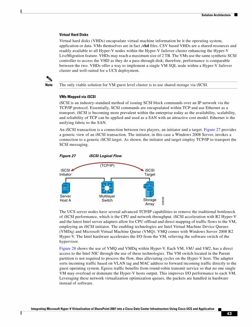
Solution Architecture
Virtual Hard Disks
Virtual hard disks (VHDs) encapsulate virtual machine information be it the operating system, application or data. VMs themselves are in fact .vhd files. CSV based VHDs are a shared resources and readily available to all Hyper-V nodes within the Hyper-V failover cluster enhancing the Hyper-V LiveMigration feature. VHDs may reach a maximum size of 2 TB. The VMs use the same synthetic SCSI controller to access the VHD as they do a pass-through disk; therefore, performance is comparable between the two. VHDs offer a way to implement a single VM SQL node within a Hyper-V failover cluster and well-suited for a UCS deployment.
Note The only viable solution for VM guest level cluster is to use shared storage via iSCSI.
VMs Mapped via iSCSI
iSCSI is an industry-standard method of issuing SCSI block commands over an IP network via the TCP/IP protocol. Essentially, SCSI commands are encapsulated within TCP and use Ethernet as a transport. iSCSI is becoming more prevalent within the enterprise today as the availability, scalability, and reliability of TCP can be applied and used as a SAN with an attractive cost model. Ethernet is the unifying fabric to the SAN.
An iSCSI transaction is a connection between two players, an initiator and a target. Figure 27 provides a generic view of an iSCSI transaction. The initiator, in this case a Windows 2008 Server, invokes a connection to a generic iSCSI target. As shown, the initiator and target employ TCP/IP to transport the SCSI messaging.
Figure 27 iSCSI Logical Flow
The UCS server nodes have several advanced TCP/IP capabilities to remove the traditional bottleneck of iSCSI performance, which is the CPU and network throughput. iSCSI acceleration with R2 Hyper-V and the latest Intel server adapters allow for CPU offload and direct mapping of traffic flows to the VM, employing an iSCSI initiator. The enabling technologies are Intel Virtual Machine Device Queues (VMDq) and Microsoft Virtual Machine Queue (VMQ). VMQ comes with Windows Server 2008 R2 Hyper-V. The Intel hardware accelerates the I/O from the VM, relieving the software switch of the hypervisor.
Figure 28 shows the use of VMQ and VMDq within Hyper-V. Each VM, VM1 and VM2, has a direct access to the Intel NIC through the use of these technologies. The VM switch located in the Parent partition is not required to process the flow, thus alleviating cycles on the Hyper-V host. The adapter sorts incoming traffic based on VLAN tag and MAC address to forward incoming traffic directly to the guest operating system. Egress traffic benefits from round-robin transmit service so that no one single VM may overload or dominate the Hyper-V hosts output. This improves I/O performance to each VM. Leveraging these network virtualization optimization queues, the packets are handled in hardware instead of software.
StorageArray
iSCSITarget
ServerHost A
MultilayerSwitch
iSCSIInitiator
2283
38(TCP/IP)
43Integrating Microsoft Hyper-V Virtualization of SharePoint 2007 into a Cisco Data Center Infrastructure Using Cisco UCS and Application
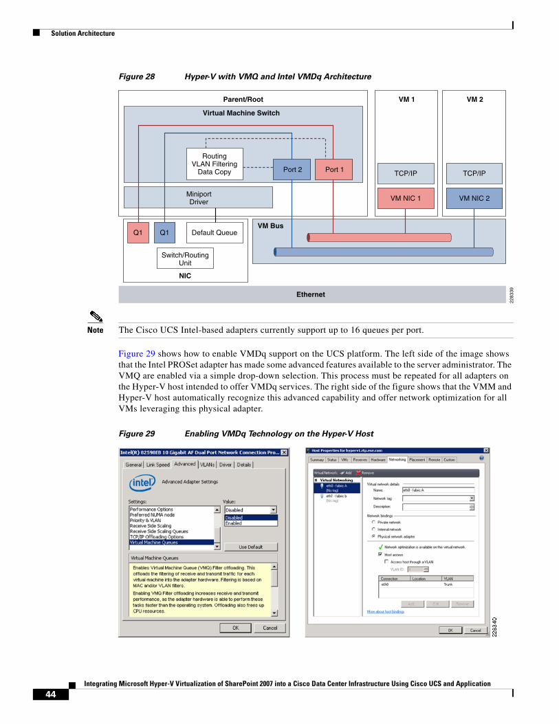
Solution Architecture
Figure 28 Hyper-V with VMQ and Intel VMDq Architecture
Note The Cisco UCS Intel-based adapters currently support up to 16 queues per port.
Figure 29 shows how to enable VMDq support on the UCS platform. The left side of the image shows that the Intel PROSet adapter has made some advanced features available to the server administrator. The VMQ are enabled via a simple drop-down selection. This process must be repeated for all adapters on the Hyper-V host intended to offer VMDq services. The right side of the figure shows that the VMM and Hyper-V host automatically recognize this advanced capability and offer network optimization for all VMs leveraging this physical adapter.
Figure 29 Enabling VMDq Technology on the Hyper-V Host
MiniportDriver
Q1 Q1
VM NIC 2
TCP/IP
VM NIC 1
TCP/IP
Default Queue
RoutingVLAN Filtering
Data Copy
Switch/RoutingUnit
NIC
VM 1Parent/Root VM 2
VM Bus
Virtual Machine Switch
2283
39Ethernet
Port 1Port 2
44Integrating Microsoft Hyper-V Virtualization of SharePoint 2007 into a Cisco Data Center Infrastructure Using Cisco UCS and Application
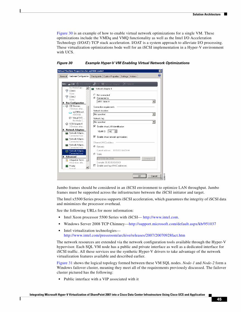
Solution Architecture
Figure 30 is an example of how to enable virtual network optimizations for a single VM. These optimizations include the VMDq and VMQ functionality as well as the Intel I/O Acceleration Technology (I/OAT) TCP stack acceleration. I/OAT is a system approach to alleviate I/O processing. These virtualization optimizations bode well for an iSCSI implementation in a Hyper-V environment with UCS.
Figure 30 Example Hyper-V VM Enabling Virtual Network Optimizations
Jumbo frames should be considered in an iSCSI environment to optimize LAN throughput. Jumbo frames must be supported across the infrastructure between the iSCSI initiator and target.
The Intel x5500 Series process supports iSCSI acceleration, which guarantees the integrity of iSCSI data and minimizes the processor overhead.
See the following URLs for more information:
• Intel Xeon processor 5500 Series with iSCSI— http://www.intel.com.
• Windows Server 2008 TCP Chimney—http://support.microsoft.com/default.aspx/kb/951037
• Intel virtualization technologies— http://www.intel.com/pressroom/archive/releases/2007/20070928fact.htm
The network resources are extended via the network configuration tools available through the Hyper-V hypervisor. Each SQL VM node has a public and private interface as well as a dedicated interface for iSCSI traffic. All these services use the synthetic Hyper-V drivers to take advantage of the network virtualization features available and described earlier.
Figure 31 shows the logical topology formed between these VM SQL nodes. Node-1 and Node-2 form a Windows failover cluster, meaning they meet all of the requirements previously discussed. The failover cluster pictured has the following:
• Public interface with a VIP associated with it
45Integrating Microsoft Hyper-V Virtualization of SharePoint 2007 into a Cisco Data Center Infrastructure Using Cisco UCS and Application
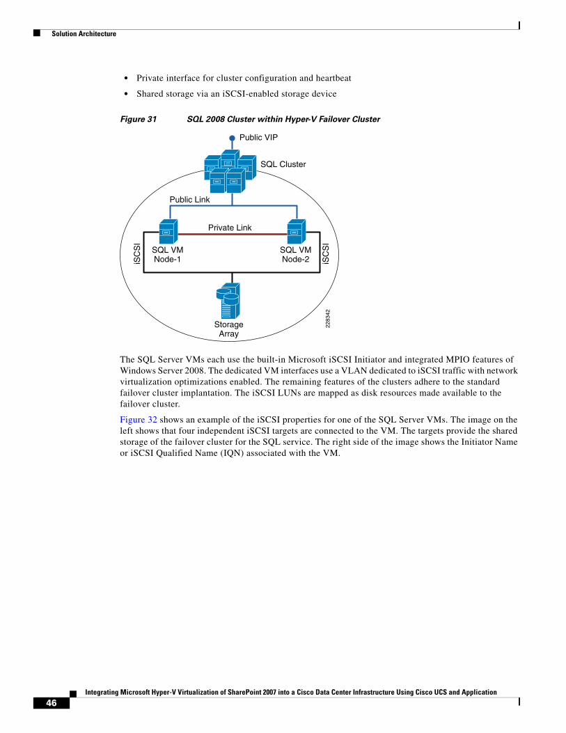
Solution Architecture
• Private interface for cluster configuration and heartbeat
• Shared storage via an iSCSI-enabled storage device
Figure 31 SQL 2008 Cluster within Hyper-V Failover Cluster
The SQL Server VMs each use the built-in Microsoft iSCSI Initiator and integrated MPIO features of Windows Server 2008. The dedicated VM interfaces use a VLAN dedicated to iSCSI traffic with network virtualization optimizations enabled. The remaining features of the clusters adhere to the standard failover cluster implantation. The iSCSI LUNs are mapped as disk resources made available to the failover cluster.
Figure 32 shows an example of the iSCSI properties for one of the SQL Server VMs. The image on the left shows that four independent iSCSI targets are connected to the VM. The targets provide the shared storage of the failover cluster for the SQL service. The right side of the image shows the Initiator Name or iSCSI Qualified Name (IQN) associated with the VM.
StorageArray
iSC
SI
iSC
SI
SQL VMNode-1
Public Link
Public VIP
Private Link
2283
42
SQL VMNode-2
SQL Cluster
46Integrating Microsoft Hyper-V Virtualization of SharePoint 2007 into a Cisco Data Center Infrastructure Using Cisco UCS and Application
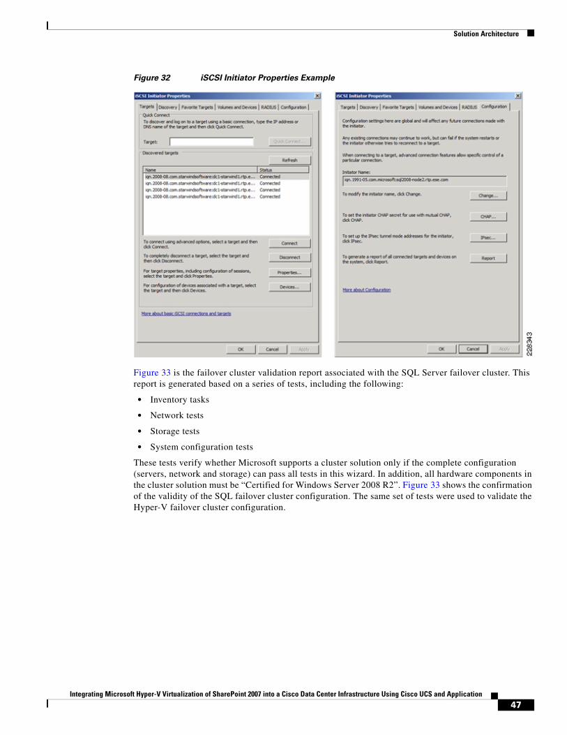
Solution Architecture
Figure 32 iSCSI Initiator Properties Example
Figure 33 is the failover cluster validation report associated with the SQL Server failover cluster. This report is generated based on a series of tests, including the following:
• Inventory tasks
• Network tests
• Storage tests
• System configuration tests
These tests verify whether Microsoft supports a cluster solution only if the complete configuration (servers, network and storage) can pass all tests in this wizard. In addition, all hardware components in the cluster solution must be “Certified for Windows Server 2008 R2”. Figure 33 shows the confirmation of the validity of the SQL failover cluster configuration. The same set of tests were used to validate the Hyper-V failover cluster configuration.
47Integrating Microsoft Hyper-V Virtualization of SharePoint 2007 into a Cisco Data Center Infrastructure Using Cisco UCS and Application
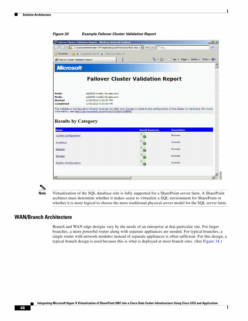
Solution Architecture
Figure 33 Example Failover Cluster Validation Report
Note Virtualization of the SQL database role is fully supported for a SharePoint server farm. A SharePoint architect must determine whether it makes sense to virtualize a SQL environment for SharePoint or whether it is more logical to choose the more traditional physical server model for the SQL server farm.
WAN/Branch Architecture
Branch and WAN edge designs vary by the needs of an enterprise at that particular site. For larger branches, a more powerful router along with separate appliances are needed. For typical branches, a single router with network modules instead of separate appliances is often sufficient. For this design, a typical branch design is used because this is what is deployed at most branch sites. (See Figure 34.)
48Integrating Microsoft Hyper-V Virtualization of SharePoint 2007 into a Cisco Data Center Infrastructure Using Cisco UCS and Application
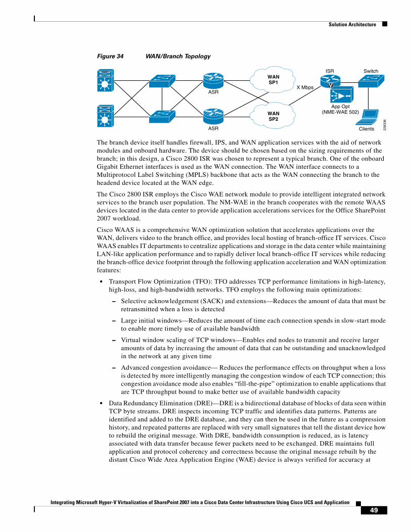
Solution Architecture
Figure 34 WAN/Branch Topology
The branch device itself handles firewall, IPS, and WAN application services with the aid of network modules and onboard hardware. The device should be chosen based on the sizing requirements of the branch; in this design, a Cisco 2800 ISR was chosen to represent a typical branch. One of the onboard Gigabit Ethernet interfaces is used as the WAN connection. The WAN interface connects to a Multiprotocol Label Switching (MPLS) backbone that acts as the WAN connecting the branch to the headend device located at the WAN edge.
The Cisco 2800 ISR employs the Cisco WAE network module to provide intelligent integrated network services to the branch user population. The NM-WAE in the branch cooperates with the remote WAAS devices located in the data center to provide application accelerations services for the Office SharePoint 2007 workload.
Cisco WAAS is a comprehensive WAN optimization solution that accelerates applications over the WAN, delivers video to the branch office, and provides local hosting of branch-office IT services. Cisco WAAS enables IT departments to centralize applications and storage in the data center while maintaining LAN-like application performance and to rapidly deliver local branch-office IT services while reducing the branch-office device footprint through the following application acceleration and WAN optimization features:
• Transport Flow Optimization (TFO): TFO addresses TCP performance limitations in high-latency, high-loss, and high-bandwidth networks. TFO employs the following main optimizations:
– Selective acknowledgement (SACK) and extensions—Reduces the amount of data that must be retransmitted when a loss is detected
– Large initial windows—Reduces the amount of time each connection spends in slow-start mode to enable more timely use of available bandwidth
– Virtual window scaling of TCP windows—Enables end nodes to transmit and receive larger amounts of data by increasing the amount of data that can be outstanding and unacknowledged in the network at any given time
– Advanced congestion avoidance— Reduces the performance effects on throughput when a loss is detected by more intelligently managing the congestion window of each TCP connection; this congestion avoidance mode also enables “fill-the-pipe” optimization to enable applications that are TCP throughput bound to make better use of available bandwidth capacity
• Data Redundancy Elimination (DRE)—DRE is a bidirectional database of blocks of data seen within TCP byte streams. DRE inspects incoming TCP traffic and identifies data patterns. Patterns are identified and added to the DRE database, and they can then be used in the future as a compression history, and repeated patterns are replaced with very small signatures that tell the distant device how to rebuild the original message. With DRE, bandwidth consumption is reduced, as is latency associated with data transfer because fewer packets need to be exchanged. DRE maintains full application and protocol coherency and correctness because the original message rebuilt by the distant Cisco Wide Area Application Engine (WAE) device is always verified for accuracy at
VASR
ASR Clients
WANSP1
WANSP2
SwitchISR
X Mbps
App Opt(NME-WAE 502)
2283
36
49Integrating Microsoft Hyper-V Virtualization of SharePoint 2007 into a Cisco Data Center Infrastructure Using Cisco UCS and Application
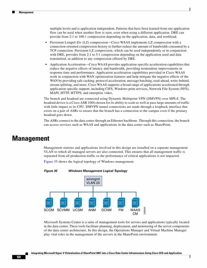
Management
multiple levels and is application independent. Patterns that have been learned from one application flow can be used when another flow is seen, even when using a different application. DRE can provide from 2:1 to 100:1 compression depending on the application, data, and workload.
• Persistent Lempel-Ziv (LZ) compression—Cisco WAAS implements LZ compression with a connection-oriented compression history to further reduce the amount of bandwidth consumed by a TCP connection. Persistent LZ compression, which can be used independently or in conjunction with DRE, provides from 2:1 to 5:1 compression depending on the application used and data transmitted, in addition to any compression offered by DRE.
• Application Acceleration—Cisco WAAS provides application-specific acceleration capabilities that reduce the negative effects of latency and bandwidth, providing tremendous improvements in response time and performance. Application acceleration capabilities provided in Cisco WAAS work in conjunction with WAN optimization features and help mitigate the negative effects of the WAN by providing safe caching, protocol acceleration, message batching, read-ahead, write-behind, stream splitting, and more. Cisco WAAS supports a broad range of applications accelerated through application-specific support, including CIFS, Windows print services, Network File System (NFS), MAPI, HTTP, HTTPS, and enterprise video.
The branch and headend are connected using Dynamic Multipoint VPN (DMVPN) over MPLS. The headend device is a Cisco ASR 1004 chosen for its ability to scale as well as pass large amounts of traffic with little impact to its CPU. DMVPN tunnel connections are made through a loopback interface that exists on a pair of ASRs to ensure that the branch has a connection to the campus even if the primary headend goes down.
The ASRs connect to the data center through an Ethernet backbone. Through this connection, the branch can access services such as WAAS and applications in the data center such as SharePoint.
ManagementManagement stations and applications involved in this design are installed on a separate management VLAN to which all managed servers are also connected. This ensures that all management traffic is separated from all production traffic so the performance of critical applications is not impacted.
Figure 35 shows the logical topology of Windows management.
Figure 35 Windows Management Logical Topology
Microsoft Systems Center is a suite of management tools for servers and applications typically located in the data center. These tools facilitate planning, deployment, and monitoring of the server components of the data center architecture. In this design, the Operations Manager and Virtual Machine Manager play vital roles in the management of the servers in the SharePoint environment.
SCVMM
2283
45UCSM ANM DCNM FM WAASCM
SCOM
winmgmtVLAN 20
50Integrating Microsoft Hyper-V Virtualization of SharePoint 2007 into a Cisco Data Center Infrastructure Using Cisco UCS and Application
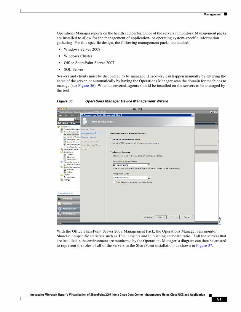
Management
Operations Manager reports on the health and performance of the servers it monitors. Management packs are installed to allow for the management of application- or operating system-specific information gathering. For this specific design, the following management packs are needed:
• Windows Server 2008
• Windows Cluster
• Office SharePoint Server 2007
• SQL Server
Servers and clients must be discovered to be managed. Discovery can happen manually by entering the name of the server, or automatically by having the Operations Manager scan the domain for machines to manage (see Figure 36). When discovered, agents should be installed on the servers to be managed by the tool.
Figure 36 Operations Manager Device Management Wizard
With the Office SharePoint Server 2007 Management Pack, the Operations Manager can monitor SharePoint-specific statistics such as Total Objects and Publishing cache hit ratio. If all the servers that are installed in the environment are monitored by the Operations Manager, a diagram can then be created to represent the roles of all of the servers in the SharePoint installation. as shown in Figure 37.
51Integrating Microsoft Hyper-V Virtualization of SharePoint 2007 into a Cisco Data Center Infrastructure Using Cisco UCS and Application
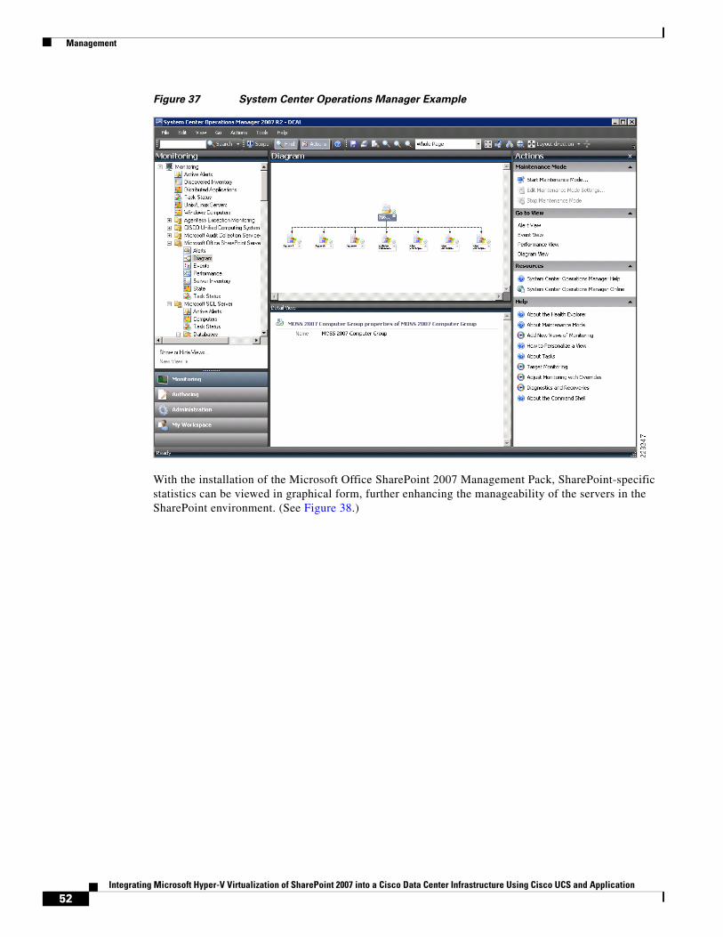
Management
Figure 37 System Center Operations Manager Example
With the installation of the Microsoft Office SharePoint 2007 Management Pack, SharePoint-specific statistics can be viewed in graphical form, further enhancing the manageability of the servers in the SharePoint environment. (See Figure 38.)
52Integrating Microsoft Hyper-V Virtualization of SharePoint 2007 into a Cisco Data Center Infrastructure Using Cisco UCS and Application
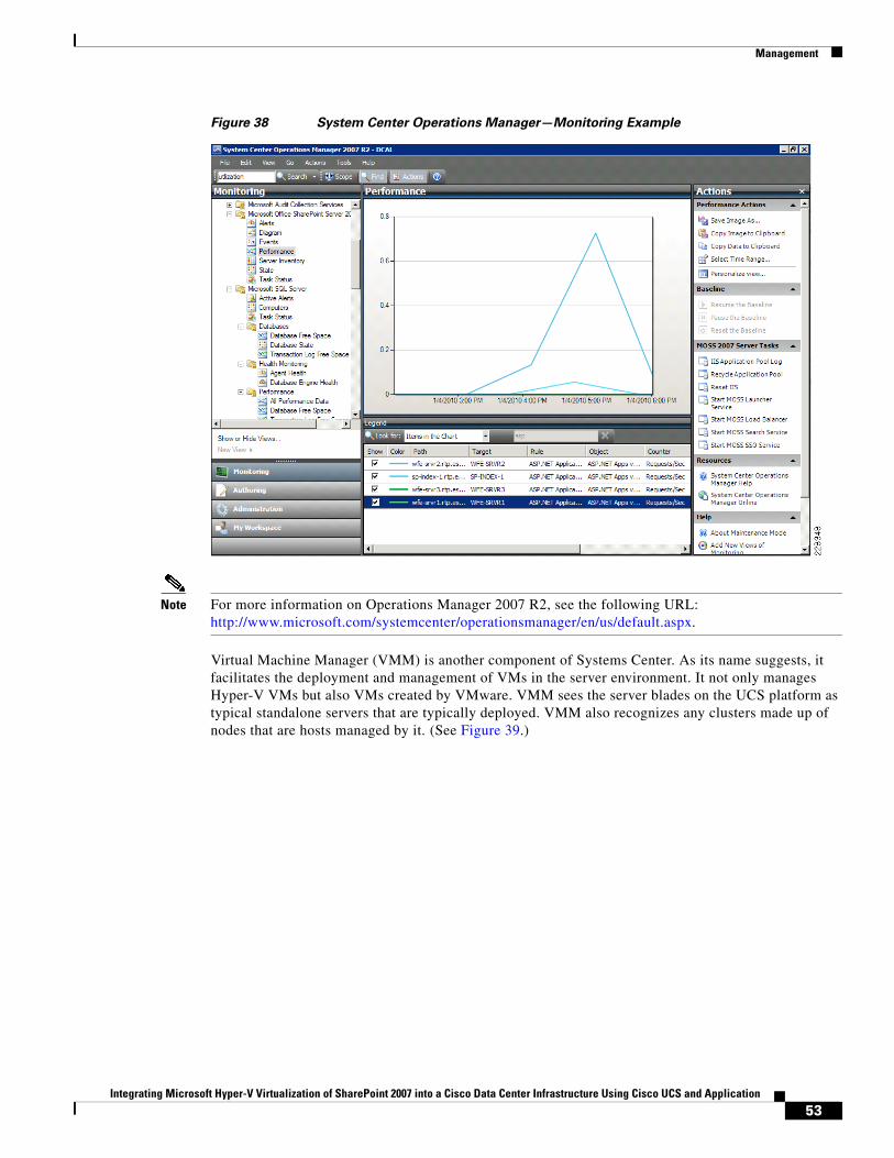
Management
Figure 38 System Center Operations Manager—Monitoring Example
Note For more information on Operations Manager 2007 R2, see the following URL: http://www.microsoft.com/systemcenter/operationsmanager/en/us/default.aspx.
Virtual Machine Manager (VMM) is another component of Systems Center. As its name suggests, it facilitates the deployment and management of VMs in the server environment. It not only manages Hyper-V VMs but also VMs created by VMware. VMM sees the server blades on the UCS platform as typical standalone servers that are typically deployed. VMM also recognizes any clusters made up of nodes that are hosts managed by it. (See Figure 39.)
53Integrating Microsoft Hyper-V Virtualization of SharePoint 2007 into a Cisco Data Center Infrastructure Using Cisco UCS and Application
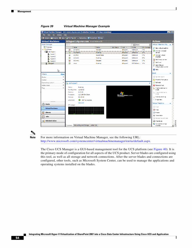
Management
Figure 39 Virtual Machine Manager Example
Note For more information on Virtual Machine Manager, see the following URL: http://www.microsoft.com/systemcenter/virtualmachinemanager/en/us/default.aspx.
The Cisco UCS Manager is a GUI-based management tool for the UCS platform (see Figure 40). It is the primary mode of configuration for all aspects of the UCS product. Server blades are configured using this tool, as well as all storage and network connections. After the server blades and connections are configured, other tools, such as Microsoft System Center, can be used to manage the applications and operating systems installed on the blades.
54Integrating Microsoft Hyper-V Virtualization of SharePoint 2007 into a Cisco Data Center Infrastructure Using Cisco UCS and Application
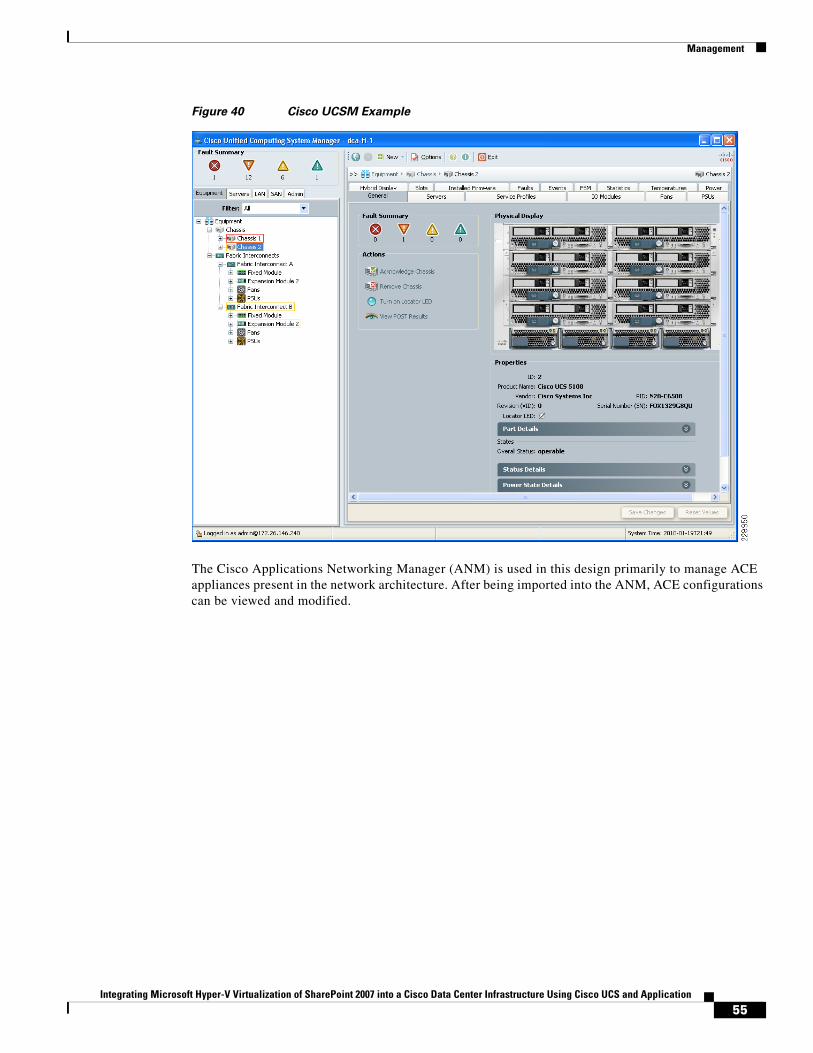
Management
Figure 40 Cisco UCSM Example
The Cisco Applications Networking Manager (ANM) is used in this design primarily to manage ACE appliances present in the network architecture. After being imported into the ANM, ACE configurations can be viewed and modified.
55Integrating Microsoft Hyper-V Virtualization of SharePoint 2007 into a Cisco Data Center Infrastructure Using Cisco UCS and Application
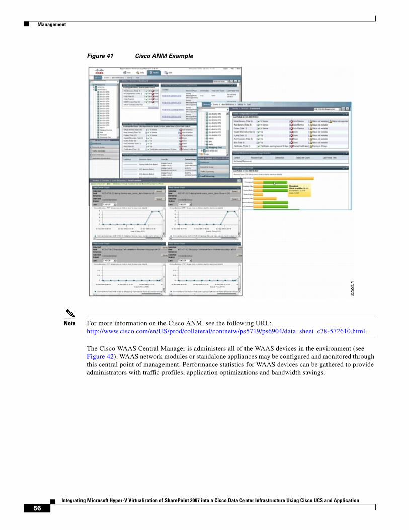
Management
Figure 41 Cisco ANM Example
Note For more information on the Cisco ANM, see the following URL: http://www.cisco.com/en/US/prod/collateral/contnetw/ps5719/ps6904/data_sheet_c78-572610.html.
The Cisco WAAS Central Manager is administers all of the WAAS devices in the environment (see Figure 42). WAAS network modules or standalone appliances may be configured and monitored through this central point of management. Performance statistics for WAAS devices can be gathered to provide administrators with traffic profiles, application optimizations and bandwidth savings.
56Integrating Microsoft Hyper-V Virtualization of SharePoint 2007 into a Cisco Data Center Infrastructure Using Cisco UCS and Application
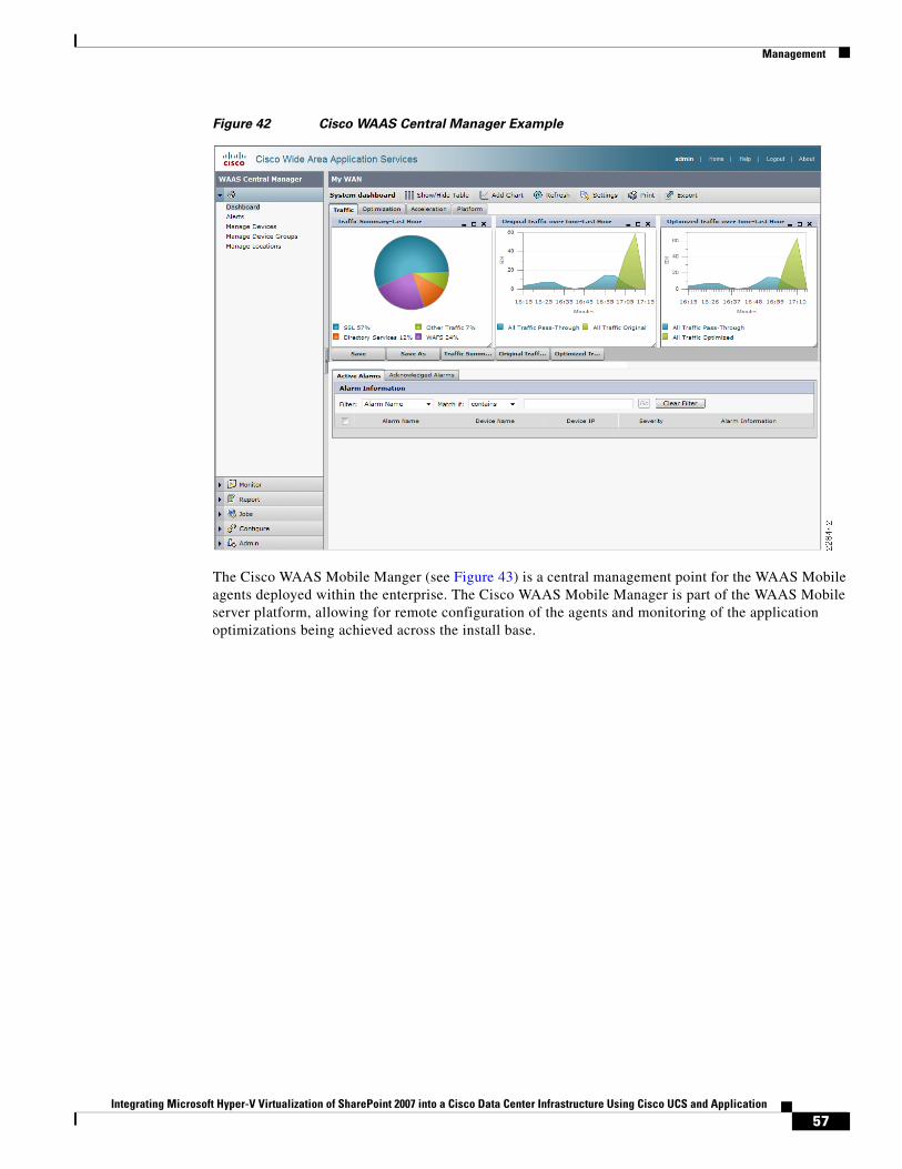
Management
Figure 42 Cisco WAAS Central Manager Example
The Cisco WAAS Mobile Manger (see Figure 43) is a central management point for the WAAS Mobile agents deployed within the enterprise. The Cisco WAAS Mobile Manager is part of the WAAS Mobile server platform, allowing for remote configuration of the agents and monitoring of the application optimizations being achieved across the install base.
57Integrating Microsoft Hyper-V Virtualization of SharePoint 2007 into a Cisco Data Center Infrastructure Using Cisco UCS and Application
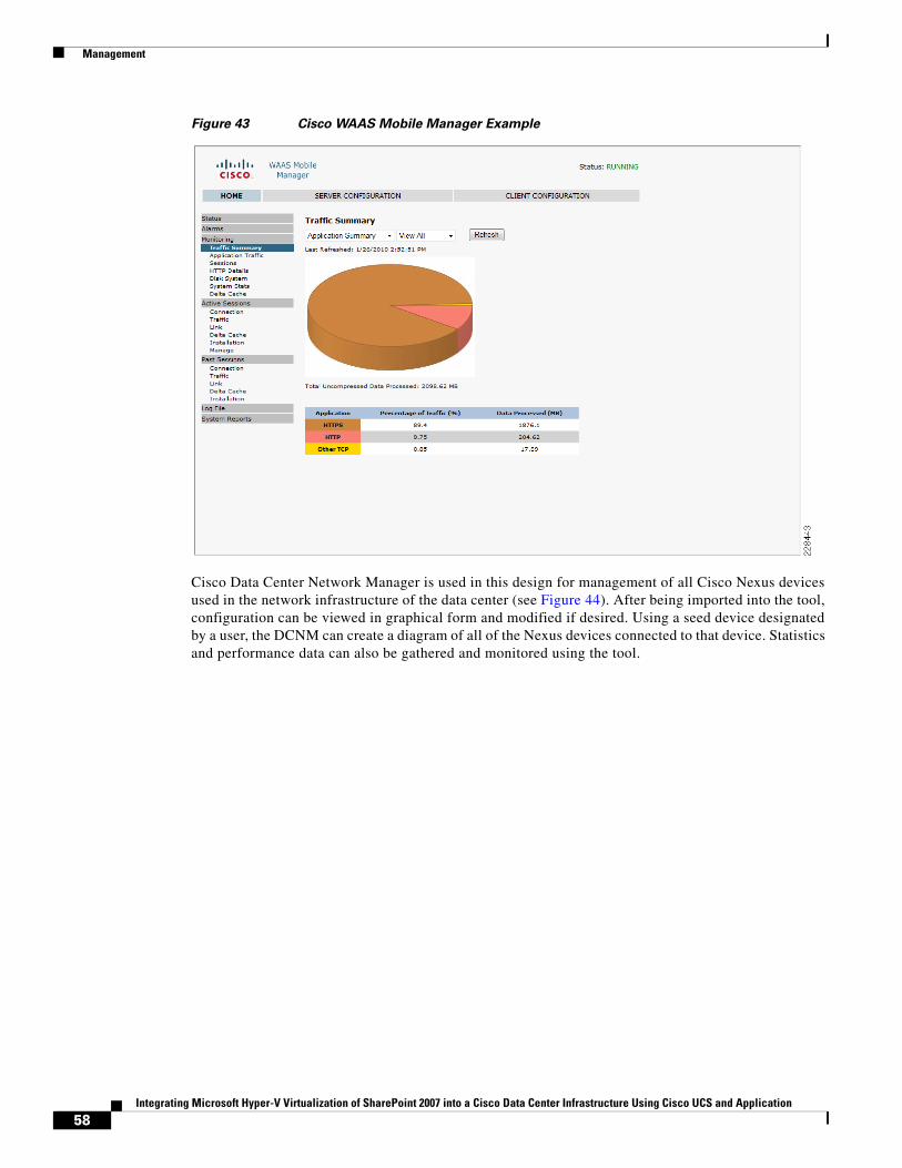
Management
Figure 43 Cisco WAAS Mobile Manager Example
Cisco Data Center Network Manager is used in this design for management of all Cisco Nexus devices used in the network infrastructure of the data center (see Figure 44). After being imported into the tool, configuration can be viewed in graphical form and modified if desired. Using a seed device designated by a user, the DCNM can create a diagram of all of the Nexus devices connected to that device. Statistics and performance data can also be gathered and monitored using the tool.
58Integrating Microsoft Hyper-V Virtualization of SharePoint 2007 into a Cisco Data Center Infrastructure Using Cisco UCS and Application
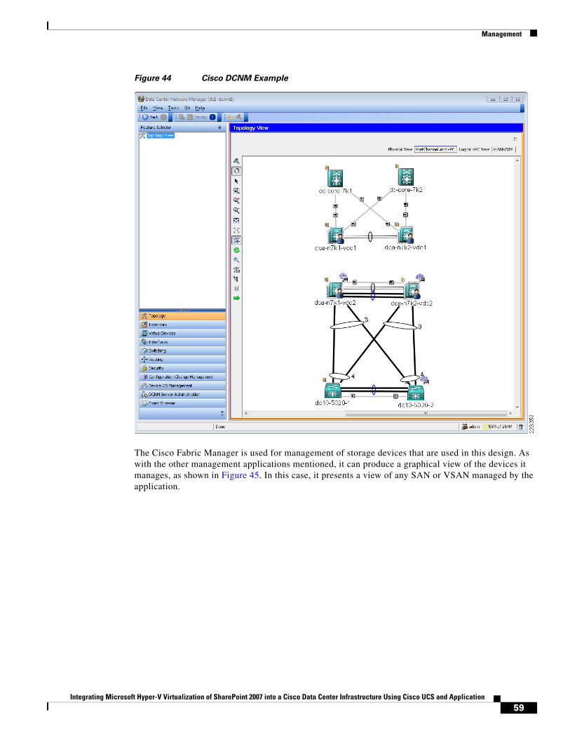
Management
Figure 44 Cisco DCNM Example
The Cisco Fabric Manager is used for management of storage devices that are used in this design. As with the other management applications mentioned, it can produce a graphical view of the devices it manages, as shown in Figure 45. In this case, it presents a view of any SAN or VSAN managed by the application.
59Integrating Microsoft Hyper-V Virtualization of SharePoint 2007 into a Cisco Data Center Infrastructure Using Cisco UCS and Application
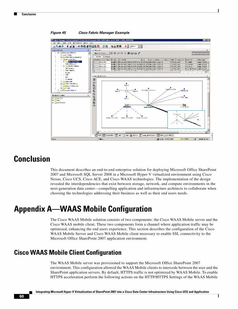
Conclusion
Figure 45 Cisco Fabric Manager Example
ConclusionThis document describes an end-to-end enterprise solution for deploying Microsoft Office SharePoint 2007 and Microsoft SQL Server 2008 in a Microsoft Hyper-V virtualized environment using Cisco Nexus, Cisco UCS, Cisco ACE, and Cisco WAAS technologies. The implementation of the design revealed the interdependencies that exist between storage, network, and compute environments in the next-generation data center—compelling application and infrastructure architects to collaborate when choosing the technologies addressing their business as well as their end users needs.
Appendix A—WAAS Mobile ConfigurationThe Cisco WAAS Mobile solution consists of two components: the Cisco WAAS Mobile server and the Cisco WAAS mobile client. These two components form a channel where application traffic may be optimized, enhancing the end users experience. This section describes the configuration of the Cisco WAAS Mobile Server and Cisco WAAS Mobile client necessary to enable SSL connectivity to the Microsoft Office SharePoint 2007 application environment.
Cisco WAAS Mobile Client ConfigurationThe WAAS Mobile server was provisioned to support the Microsoft Office SharePoint 2007 environment. This configuration allowed the WAAS Mobile clients to intercede between the user and the SharePoint application servers. By default, HTTPS traffic is not optimized by WAAS Mobile. To enable HTTPS acceleration perform the following actions on the HTTP/HTTPS Settings of the WAAS Mobile
60Integrating Microsoft Hyper-V Virtualization of SharePoint 2007 into a Cisco Data Center Infrastructure Using Cisco UCS and Application
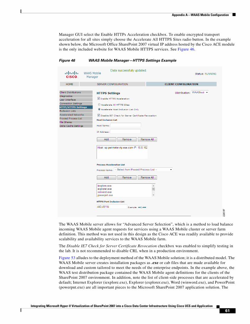
Appendix A—WAAS Mobile Configuration
Manager GUI select the Enable HTTPs Acceleration checkbox. To enable encrypted transport acceleration for all sites simply choose the Accelerate All HTTPS Sites radio button. In the example shown below, the Microsoft Office SharePoint 2007 virtual IP address hosted by the Cisco ACE module is the only included website for WAAS Mobile HTTPS services. See Figure 46.
Figure 46 WAAS Mobile Manager—HTTPS Settings Example
The WAAS Mobile server allows for “Advanced Server Selection”, which is a method to load balance incoming WAAS Mobile agent requests for services using a WAAS Mobile cluster or server farm definition. This method was not used in this design as the Cisco ACE was readily available to provide scalability and availability services to the WAAS Mobile farm.
The Disable IE7 Check for Server Certificate Revocation checkbox was enabled to simplify testing in the lab. It is not recommended to disable CRL when in a production environment.
Figure 53 alludes to the deployment method of the WAAS Mobile solution; it is a distributed model. The WAAS Mobile server creates installation packages as .exe or cab files that are made available for download and custom tailored to meet the needs of the enterprise endpoints. In the example above, the WAAS test distribution package contained the WAAS Mobile agent definitions for the clients of the SharePoint 2007 environment. In addition, note the list of client-side processes that are accelerated by default; Internet Explorer (iexplore.exe), Explorer (explorer.exe), Word (winword.exe), and PowerPoint (powerpnt.exe) are all important pieces to the Microsoft SharePoint 2007 application solution. The
61Integrating Microsoft Hyper-V Virtualization of SharePoint 2007 into a Cisco Data Center Infrastructure Using Cisco UCS and Application
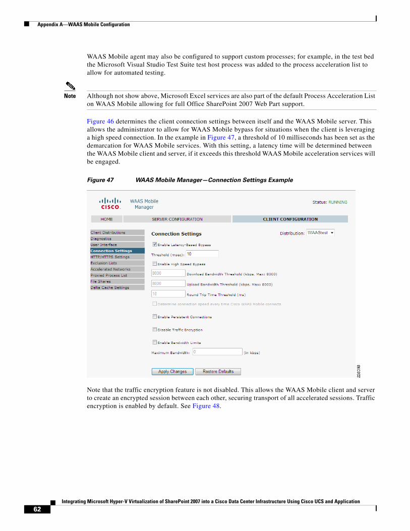
Appendix A—WAAS Mobile Configuration
WAAS Mobile agent may also be configured to support custom processes; for example, in the test bed the Microsoft Visual Studio Test Suite test host process was added to the process acceleration list to allow for automated testing.
Note Although not show above, Microsoft Excel services are also part of the default Process Acceleration List on WAAS Mobile allowing for full Office SharePoint 2007 Web Part support.
Figure 46 determines the client connection settings between itself and the WAAS Mobile server. This allows the administrator to allow for WAAS Mobile bypass for situations when the client is leveraging a high speed connection. In the example in Figure 47, a threshold of 10 milliseconds has been set as the demarcation for WAAS Mobile services. With this setting, a latency time will be determined between the WAAS Mobile client and server, if it exceeds this threshold WAAS Mobile acceleration services will be engaged.
Figure 47 WAAS Mobile Manager—Connection Settings Example
Note that the traffic encryption feature is not disabled. This allows the WAAS Mobile client and server to create an encrypted session between each other, securing transport of all accelerated sessions. Traffic encryption is enabled by default. See Figure 48.
62Integrating Microsoft Hyper-V Virtualization of SharePoint 2007 into a Cisco Data Center Infrastructure Using Cisco UCS and Application
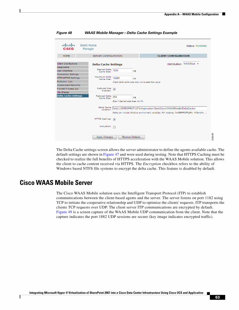
Appendix A—WAAS Mobile Configuration
Figure 48 WAAS Mobile Manager—Delta Cache Settings Example
The Delta Cache settings screen allows the server administrator to define the agents available cache. The default settings are shown in Figure 47 and were used during testing. Note that HTTPS Caching must be checked to realize the full benefits of HTTPS acceleration with the WAAS Mobile solution. This allows the client to cache content received via HTTPS. The Encryption checkbox refers to the ability of Windows based NTFS file systems to encrypt the delta cache. This feature is disabled by default.
Cisco WAAS Mobile ServerThe Cisco WAAS Mobile solution uses the Intelligent Transport Protocol (ITP) to establish communications between the client-based agents and the server. The server listens on port 1182 using TCP to initiate the cooperative relationship and UDP to optimize the clients' requests. ITP transports the clients TCP requests over UDP. The client server ITP communications are encrypted by default. Figure 49 is a screen capture of the WAAS Mobile UDP communication from the client. Note that the capture indicates the port 1882 UDP sessions are secure (key image indicates encrypted traffic).
63Integrating Microsoft Hyper-V Virtualization of SharePoint 2007 into a Cisco Data Center Infrastructure Using Cisco UCS and Application
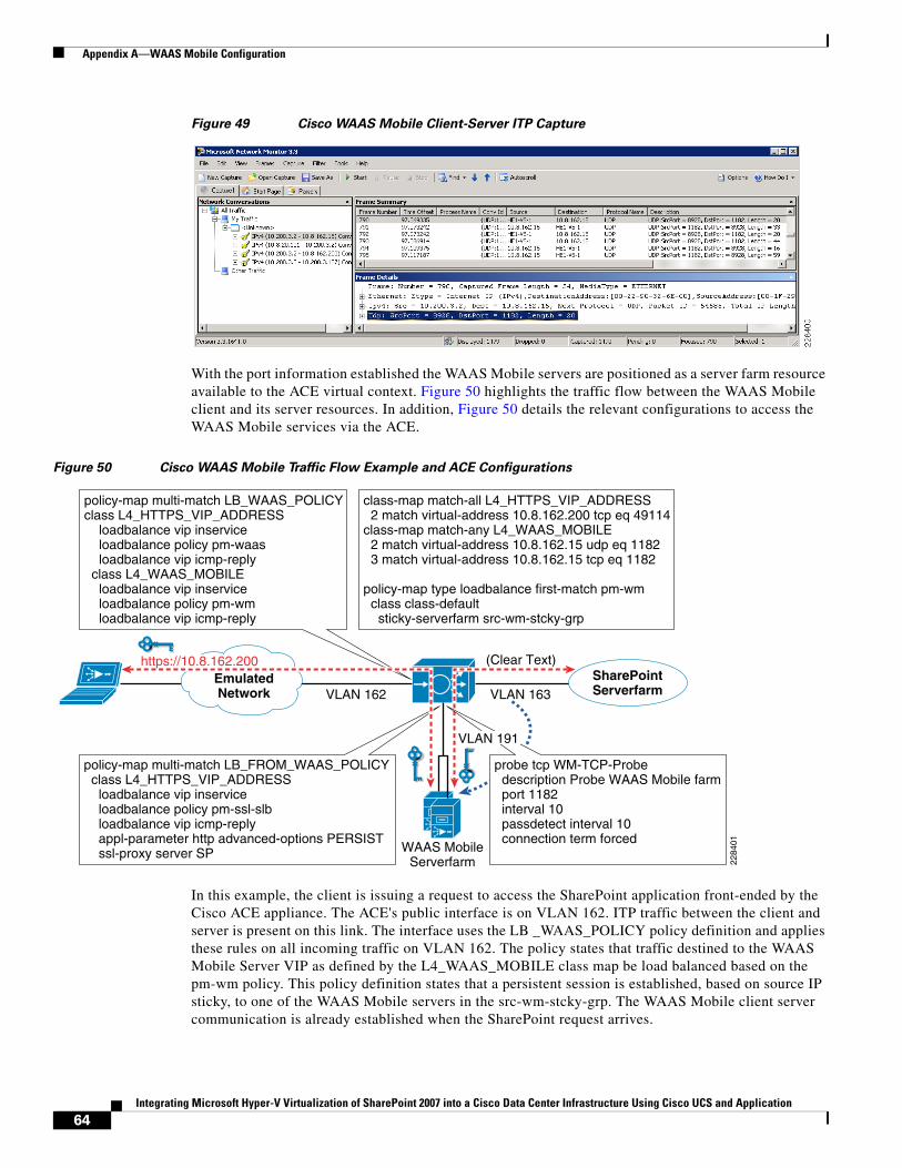
Appendix A—WAAS Mobile Configuration
Figure 49 Cisco WAAS Mobile Client-Server ITP Capture
With the port information established the WAAS Mobile servers are positioned as a server farm resource available to the ACE virtual context. Figure 50 highlights the traffic flow between the WAAS Mobile client and its server resources. In addition, Figure 50 details the relevant configurations to access the WAAS Mobile services via the ACE.
Figure 50 Cisco WAAS Mobile Traffic Flow Example and ACE Configurations
In this example, the client is issuing a request to access the SharePoint application front-ended by the Cisco ACE appliance. The ACE's public interface is on VLAN 162. ITP traffic between the client and server is present on this link. The interface uses the LB _WAAS_POLICY policy definition and applies these rules on all incoming traffic on VLAN 162. The policy states that traffic destined to the WAAS Mobile Server VIP as defined by the L4_WAAS_MOBILE class map be load balanced based on the pm-wm policy. This policy definition states that a persistent session is established, based on source IP sticky, to one of the WAAS Mobile servers in the src-wm-stcky-grp. The WAAS Mobile client server communication is already established when the SharePoint request arrives.
policy-map multi-match LB_FROM_WAAS_POLICY class L4_HTTPS_VIP_ADDRESS loadbalance vip inservice loadbalance policy pm-ssl-slb loadbalance vip icmp-reply appl-parameter http advanced-options PERSIST ssl-proxy server SP
policy-map multi-match LB_WAAS_POLICYclass L4_HTTPS_VIP_ADDRESS loadbalance vip inservice loadbalance policy pm-waas loadbalance vip icmp-reply class L4_WAAS_MOBILE loadbalance vip inservice loadbalance policy pm-wm loadbalance vip icmp-reply
class-map match-all L4_HTTPS_VIP_ADDRESS 2 match virtual-address 10.8.162.200 tcp eq 49114class-map match-any L4_WAAS_MOBILE 2 match virtual-address 10.8.162.15 udp eq 1182 3 match virtual-address 10.8.162.15 tcp eq 1182
policy-map type loadbalance first-match pm-wm class class-default sticky-serverfarm src-wm-stcky-grp
EmulatedNetwork
SharePointServerfarm
WAAS MobileServerfarm
(Clear Text)
VLAN 162 VLAN 163
2284
01
https://10.8.162.200
probe tcp WM-TCP-Probe description Probe WAAS Mobile farm port 1182 interval 10 passdetect interval 10 connection term forced
VLAN 191
64Integrating Microsoft Hyper-V Virtualization of SharePoint 2007 into a Cisco Data Center Infrastructure Using Cisco UCS and Application
Appendix B—WAAS Configuration
The WAAS Mobile farm resides on VLAN 191, a VLAN dedicated to WAAS services. The request is received by the WAAS Mobile server previously selected by the ACE's load balancing hash. The WAAS Mobile server processes the request and initiates a secure connection to the Office SharePoint 2007 application. The L4_HTTPS_VIP_ADDRESS VIP address as defined under policy map LB_FROM_WAAS_POLICY on VLAN 191 is the target of this request. The SharePoint VIP uses SSL termination services and consistently enforces SSL URL rewrite via the PERSIST application parameter map. The ACE load balances the request to a SharePoint front-end server and completes the connection.
Note The ACE provides health monitoring functionality of the WAAS Mobile server farm. The probes are TCP-based and simply test the state of the WAAS Mobile service listening on port 1182. If a TCP session is successfully established, it is assumed the WAAS Mobile server process is functioning properly. The connection term forced forces a reset of the TCP session to preserve server resources.
Appendix B—WAAS ConfigurationThe Cisco WAAS appliances and network modules support secure end-to-end application acceleration services. This appendix focuses on the portions of the configuration necessary to support SSL across the WAN to the Office SharePoint 2007 application environment.
Figure 51 illustrates the secure transport of SharePoint requests across the tested topology. In this example, the client issues a HTTPS request to the VIP on the ACE associated with the Office SharePoint 2007 application farm. The remote clients request is redirected via WCCP to the WAE network module physically located within the ISR. The WAE at this point uses an SSL application acceleration service previously defined by the WAAS administrator.
Figure 52 is the SSL accelerated service delineated for the SharePoint 2007 application. The certificate is imported into the WAAS central manager. It is only distributed to the members of the data center WAAS farm via a group policy definition on the WAAS Central Manager. Note that the Service Address/Port configuration matches the ACE VIP present on VLAN 162. In fact, the certificate used for the SSL termination services and employed by the WAAS appliances are one in the same, they must be consistent across the WAEs in the data center and the ACE SSL proxy service.
The WAAS device in the data center participates in the SSL handshake negotiation with the client in the branch. This long distance negotiation result in two SSL session keys, keys A and B. Key A exists between the client and the WAAS appliance in the data center. Key C exists between the same WAAS appliance and the ACE SSL proxy-service for the SharePoint application.
After each session key has been negotiated, keys A and C respectively, a copy of key A is securely sent to the branch WAE using an encrypted peering session. Key B is the peering session key shown below that exists only between the two WAAS devices. The SSL session key A is now securely available on the branch WAE, allowing the WAEs in the branch and datacenter to decrypt and re-encrypt traffic transparently between the SharePoint application and the client in the branch. Exposing the data allows the WAAS devices to offer DRE and LZ compression in addition to TFO optimizations.
65Integrating Microsoft Hyper-V Virtualization of SharePoint 2007 into a Cisco Data Center Infrastructure Using Cisco UCS and Application
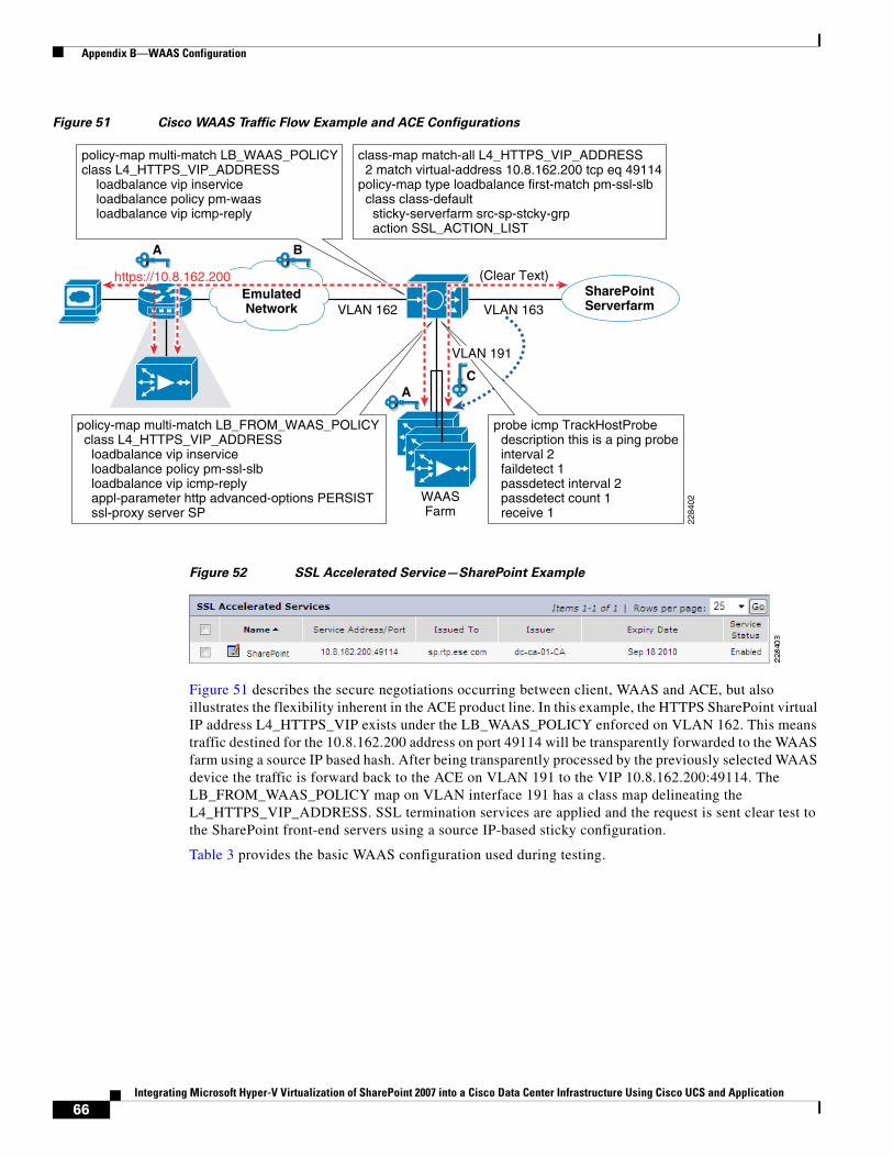
Appendix B—WAAS Configuration
Figure 51 Cisco WAAS Traffic Flow Example and ACE Configurations
Figure 52 SSL Accelerated Service—SharePoint Example
Figure 51 describes the secure negotiations occurring between client, WAAS and ACE, but also illustrates the flexibility inherent in the ACE product line. In this example, the HTTPS SharePoint virtual IP address L4_HTTPS_VIP exists under the LB_WAAS_POLICY enforced on VLAN 162. This means traffic destined for the 10.8.162.200 address on port 49114 will be transparently forwarded to the WAAS farm using a source IP based hash. After being transparently processed by the previously selected WAAS device the traffic is forward back to the ACE on VLAN 191 to the VIP 10.8.162.200:49114. The LB_FROM_WAAS_POLICY map on VLAN interface 191 has a class map delineating the L4_HTTPS_VIP_ADDRESS. SSL termination services are applied and the request is sent clear test to the SharePoint front-end servers using a source IP-based sticky configuration.
Table 3 provides the basic WAAS configuration used during testing.
policy-map multi-match LB_FROM_WAAS_POLICY class L4_HTTPS_VIP_ADDRESS loadbalance vip inservice loadbalance policy pm-ssl-slb loadbalance vip icmp-reply appl-parameter http advanced-options PERSIST ssl-proxy server SP
policy-map multi-match LB_WAAS_POLICYclass L4_HTTPS_VIP_ADDRESS loadbalance vip inservice loadbalance policy pm-waas loadbalance vip icmp-reply
class-map match-all L4_HTTPS_VIP_ADDRESS 2 match virtual-address 10.8.162.200 tcp eq 49114policy-map type loadbalance first-match pm-ssl-slb class class-default sticky-serverfarm src-sp-stcky-grp action SSL_ACTION_LIST
EmulatedNetwork
A
SharePointServerfarm
(Clear Text)
VLAN 162 VLAN 163
2284
02
https://10.8.162.200
probe icmp TrackHostProbe description this is a ping probe interval 2 faildetect 1 passdetect interval 2 passdetect count 1 receive 1
VLAN 191
A
B
C
WAASFarm
66Integrating Microsoft Hyper-V Virtualization of SharePoint 2007 into a Cisco Data Center Infrastructure Using Cisco UCS and Application
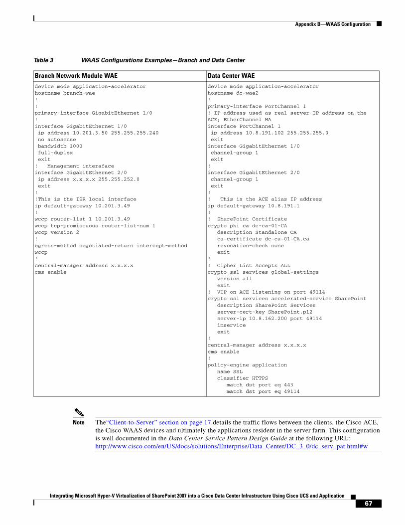
Appendix B—WAAS Configuration
Note The“Client-to-Server” section on page 17 details the traffic flows between the clients, the Cisco ACE, the Cisco WAAS devices and ultimately the applications resident in the server farm. This configuration is well documented in the Data Center Service Pattern Design Guide at the following URL: http://www.cisco.com/en/US/docs/solutions/Enterprise/Data_Center/DC_3_0/dc_serv_pat.html#w
Table 3 WAAS Configurations Examples—Branch and Data Center
Branch Network Module WAE Data Center WAE
device mode application-acceleratorhostname branch-wae!!primary-interface GigabitEthernet 1/0! interface GigabitEthernet 1/0 ip address 10.201.3.50 255.255.255.240 no autosense bandwidth 1000 full-duplex exit! Management interafaceinterface GigabitEthernet 2/0 ip address x.x.x.x 255.255.252.0 exit!!This is the ISR local interfaceip default-gateway 10.201.3.49!wccp router-list 1 10.201.3.49wccp tcp-promiscuous router-list-num 1wccp version 2!egress-method negotiated-return intercept-method wccp!central-manager address x.x.x.xcms enable
device mode application-acceleratorhostname dc-wae2!primary-interface PortChannel 1! IP address used as real server IP address on the ACE; EtherChannel HAinterface PortChannel 1 ip address 10.8.191.102 255.255.255.0 exitinterface GigabitEthernet 1/0 channel-group 1 exit! interface GigabitEthernet 2/0 channel-group 1 exit!! This is the ACE alias IP addressip default-gateway 10.8.191.1!! SharePoint Certificatecrypto pki ca dc-ca-01-CA description Standalone CA ca-certificate dc-ca-01-CA.ca revocation-check none exit!! Cipher List Accepts ALLcrypto ssl services global-settings version all exit! VIP on ACE listening on port 49114crypto ssl services accelerated-service SharePoint description SharePoint Services server-cert-key SharePoint.p12 server-ip 10.8.162.200 port 49114 inservice exit!central-manager address x.x.x.xcms enable!policy-engine application name SSL classifier HTTPS match dst port eq 443 match dst port eq 49114
67Integrating Microsoft Hyper-V Virtualization of SharePoint 2007 into a Cisco Data Center Infrastructure Using Cisco UCS and Application
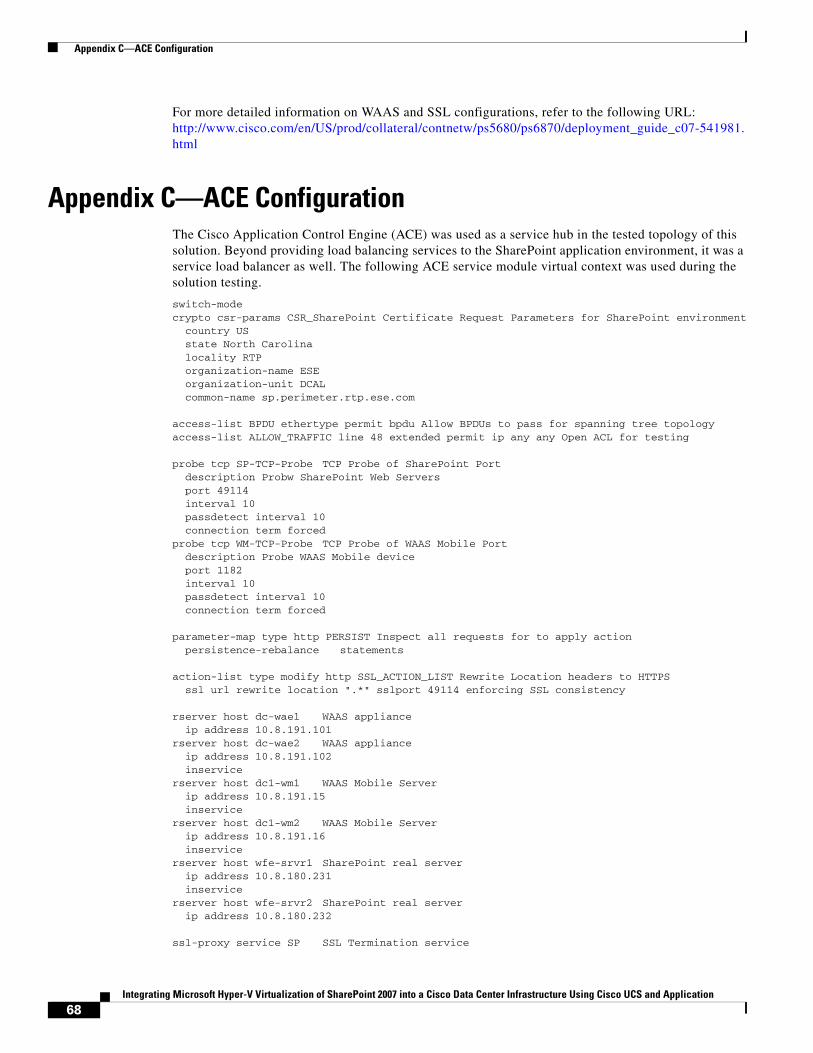
Appendix C—ACE Configuration
For more detailed information on WAAS and SSL configurations, refer to the following URL: http://www.cisco.com/en/US/prod/collateral/contnetw/ps5680/ps6870/deployment_guide_c07-541981.html
Appendix C—ACE ConfigurationThe Cisco Application Control Engine (ACE) was used as a service hub in the tested topology of this solution. Beyond providing load balancing services to the SharePoint application environment, it was a service load balancer as well. The following ACE service module virtual context was used during the solution testing.
switch-modecrypto csr-params CSR_SharePoint Certificate Request Parameters for SharePoint environment country US state North Carolina locality RTP organization-name ESE organization-unit DCAL common-name sp.perimeter.rtp.ese.com
access-list BPDU ethertype permit bpdu Allow BPDUs to pass for spanning tree topologyaccess-list ALLOW_TRAFFIC line 48 extended permit ip any any Open ACL for testing
probe tcp SP-TCP-Probe TCP Probe of SharePoint Port description Probw SharePoint Web Servers port 49114 interval 10 passdetect interval 10 connection term forcedprobe tcp WM-TCP-Probe TCP Probe of WAAS Mobile Port description Probe WAAS Mobile device port 1182 interval 10 passdetect interval 10 connection term forced
parameter-map type http PERSIST Inspect all requests for to apply action persistence-rebalance statements
action-list type modify http SSL_ACTION_LIST Rewrite Location headers to HTTPS ssl url rewrite location ".*" sslport 49114 enforcing SSL consistency
rserver host dc-wae1 WAAS appliance ip address 10.8.191.101rserver host dc-wae2 WAAS appliance ip address 10.8.191.102 inservicerserver host dc1-wm1 WAAS Mobile Server ip address 10.8.191.15 inservicerserver host dc1-wm2 WAAS Mobile Server ip address 10.8.191.16 inservicerserver host wfe-srvr1 SharePoint real server ip address 10.8.180.231 inservicerserver host wfe-srvr2 SharePoint real server ip address 10.8.180.232
ssl-proxy service SP SSL Termination service
68Integrating Microsoft Hyper-V Virtualization of SharePoint 2007 into a Cisco Data Center Infrastructure Using Cisco UCS and Application
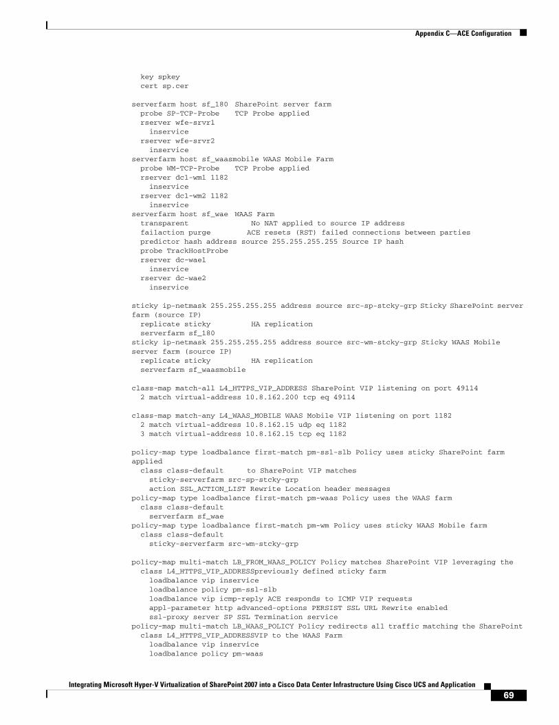
Appendix C—ACE Configuration
key spkey cert sp.cer
serverfarm host sf_180 SharePoint server farm probe SP-TCP-Probe TCP Probe applied rserver wfe-srvr1 inservice rserver wfe-srvr2 inserviceserverfarm host sf_waasmobile WAAS Mobile Farm probe WM-TCP-Probe TCP Probe applied rserver dc1-wm1 1182 inservice rserver dc1-wm2 1182 inserviceserverfarm host sf_wae WAAS Farm transparent No NAT applied to source IP address failaction purge ACE resets (RST) failed connections between parties predictor hash address source 255.255.255.255 Source IP hash probe TrackHostProbe rserver dc-wae1 inservice rserver dc-wae2 inservice
sticky ip-netmask 255.255.255.255 address source src-sp-stcky-grp Sticky SharePoint server farm (source IP) replicate sticky HA replication serverfarm sf_180sticky ip-netmask 255.255.255.255 address source src-wm-stcky-grp Sticky WAAS Mobile server farm (source IP) replicate sticky HA replication serverfarm sf_waasmobile
class-map match-all L4_HTTPS_VIP_ADDRESS SharePoint VIP listening on port 49114 2 match virtual-address 10.8.162.200 tcp eq 49114
class-map match-any L4_WAAS_MOBILE WAAS Mobile VIP listening on port 1182 2 match virtual-address 10.8.162.15 udp eq 1182 3 match virtual-address 10.8.162.15 tcp eq 1182
policy-map type loadbalance first-match pm-ssl-slb Policy uses sticky SharePoint farm applied class class-default to SharePoint VIP matches sticky-serverfarm src-sp-stcky-grp action SSL_ACTION_LIST Rewrite Location header messagespolicy-map type loadbalance first-match pm-waas Policy uses the WAAS farm class class-default serverfarm sf_waepolicy-map type loadbalance first-match pm-wm Policy uses sticky WAAS Mobile farm class class-default sticky-serverfarm src-wm-stcky-grp
policy-map multi-match LB_FROM_WAAS_POLICY Policy matches SharePoint VIP leveraging the class L4_HTTPS_VIP_ADDRESSpreviously defined sticky farm loadbalance vip inservice loadbalance policy pm-ssl-slb loadbalance vip icmp-reply ACE responds to ICMP VIP requests appl-parameter http advanced-options PERSIST SSL URL Rewrite enabled ssl-proxy server SP SSL Termination servicepolicy-map multi-match LB_WAAS_POLICY Policy redirects all traffic matching the SharePoint class L4_HTTPS_VIP_ADDRESSVIP to the WAAS Farm loadbalance vip inservice loadbalance policy pm-waas
69Integrating Microsoft Hyper-V Virtualization of SharePoint 2007 into a Cisco Data Center Infrastructure Using Cisco UCS and Application
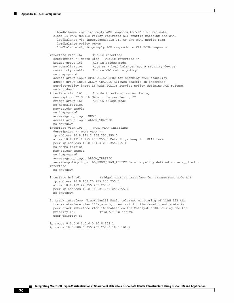
Appendix C—ACE Configuration
loadbalance vip icmp-reply ACE responds to VIP ICMP requests class L4_WAAS_MOBILE Policy redirects all traffic matching the WAAS loadbalance vip inserviceMobile VIP to the WAAS Mobile Farm loadbalance policy pm-wm loadbalance vip icmp-reply ACE responds to VIP ICMP requests
interface vlan 162 Public interface description ** North Side - Public Interface ** bridge-group 161 ACE in bridge mode no normalization Acts as a load balancer not a security device mac-sticky enable Source MAC return policy no icmp-guard access-group input BPDU Allow BPDU for spanning tree stability access-group input ALLOW_TRAFFIC Allowed traffic on interface service-policy input LB_WAAS_POLICY Service policy defining ACE ruleset no shutdowninterface vlan 163 Inside interface, server facing description ** South Side - Server Facing ** bridge-group 161 ACE in bridge mode no normalization mac-sticky enable no icmp-guard access-group input BPDU access-group input ALLOW_TRAFFIC no shutdowninterface vlan 191 WAAS VLAN interface description ** WAAS VLAN ** ip address 10.8.191.2 255.255.255.0 alias 10.8.191.1 255.255.255.0 Default gateway for WAAS farm peer ip address 10.8.191.3 255.255.255.0 no normalization mac-sticky enable no icmp-guard access-group input ALLOW_TRAFFIC service-policy input LB_FROM_WAAS_POLICY Service policy defined above applied to interface no shutdown
interface bvi 161 Bridged virtual interface for transparent mode ACE ip address 10.8.162.20 255.255.255.0 alias 10.8.162.22 255.255.255.0 peer ip address 10.8.162.21 255.255.255.0 no shutdown
ft track interface TrackVlan163 Fault tolerant monitoring of VLAN 163 the track-interface vlan 163spanning tree root for the domain, autostate is peer track-interface vlan 163enabled on the Catalyst 6500 housing the ACE priority 150 This ACE is active peer priority 50
ip route 0.0.0.0 0.0.0.0 10.8.162.1ip route 10.8.180.0 255.255.255.0 10.8.162.7
70Integrating Microsoft Hyper-V Virtualization of SharePoint 2007 into a Cisco Data Center Infrastructure Using Cisco UCS and Application
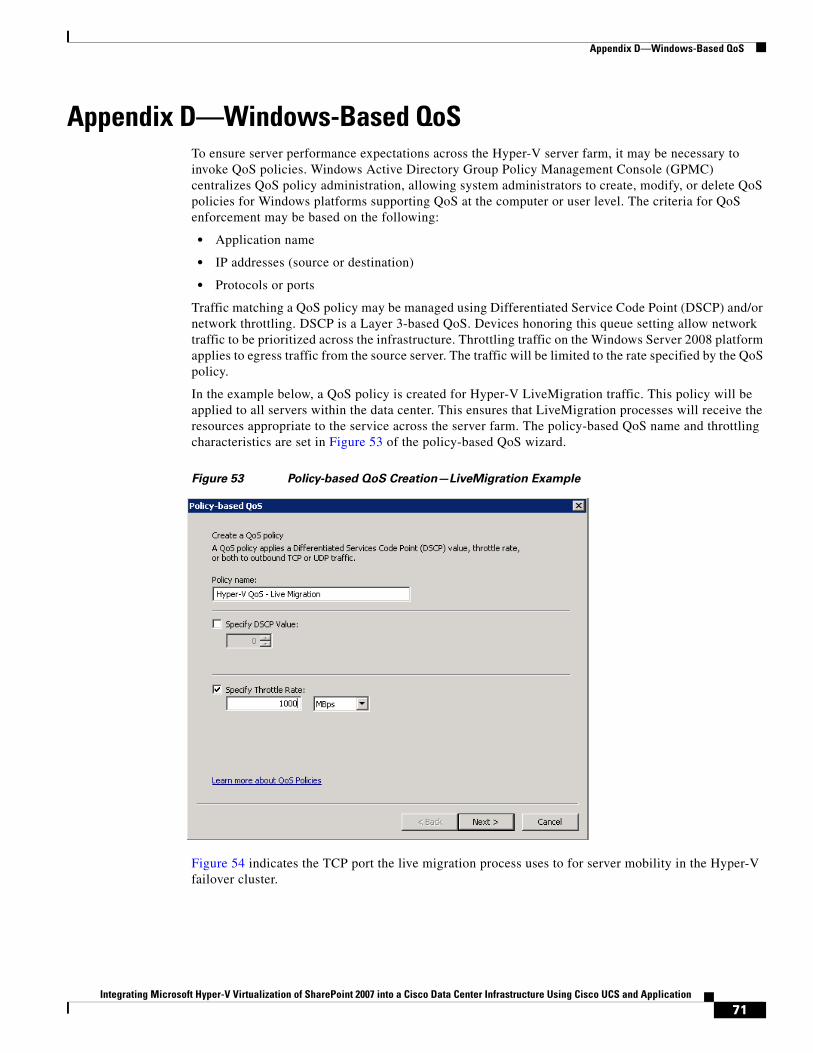
Appendix D—Windows-Based QoS
Appendix D—Windows-Based QoSTo ensure server performance expectations across the Hyper-V server farm, it may be necessary to invoke QoS policies. Windows Active Directory Group Policy Management Console (GPMC) centralizes QoS policy administration, allowing system administrators to create, modify, or delete QoS policies for Windows platforms supporting QoS at the computer or user level. The criteria for QoS enforcement may be based on the following:
• Application name
• IP addresses (source or destination)
• Protocols or ports
Traffic matching a QoS policy may be managed using Differentiated Service Code Point (DSCP) and/or network throttling. DSCP is a Layer 3-based QoS. Devices honoring this queue setting allow network traffic to be prioritized across the infrastructure. Throttling traffic on the Windows Server 2008 platform applies to egress traffic from the source server. The traffic will be limited to the rate specified by the QoS policy.
In the example below, a QoS policy is created for Hyper-V LiveMigration traffic. This policy will be applied to all servers within the data center. This ensures that LiveMigration processes will receive the resources appropriate to the service across the server farm. The policy-based QoS name and throttling characteristics are set in Figure 53 of the policy-based QoS wizard.
Figure 53 Policy-based QoS Creation—LiveMigration Example
Figure 54 indicates the TCP port the live migration process uses to for server mobility in the Hyper-V failover cluster.
71Integrating Microsoft Hyper-V Virtualization of SharePoint 2007 into a Cisco Data Center Infrastructure Using Cisco UCS and Application
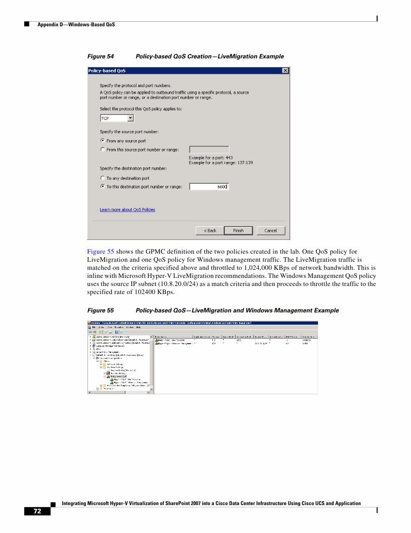
Appendix D—Windows-Based QoS
Figure 54 Policy-based QoS Creation—LiveMigration Example
Figure 55 shows the GPMC definition of the two policies created in the lab. One QoS policy for LiveMigration and one QoS policy for Windows management traffic. The LiveMigration traffic is matched on the criteria specified above and throttled to 1,024,000 KBps of network bandwidth. This is inline with Microsoft Hyper-V LiveMigration recommendations. The Windows Management QoS policy uses the source IP subnet (10.8.20.0/24) as a match criteria and then proceeds to throttle the traffic to the specified rate of 102400 KBps.
Figure 55 Policy-based QoS—LiveMigration and Windows Management Example
72Integrating Microsoft Hyper-V Virtualization of SharePoint 2007 into a Cisco Data Center Infrastructure Using Cisco UCS and Application
Additional References
Additional References• Data Center Service Patterns—
http://www.cisco.com/en/US/docs/solutions/Enterprise/Data_Center/DC_3_0/dc_serv_pat.html#wp1037942
• Security and Virtualization in the Data Center— http://www.cisco.com/en/US/docs/solutions/Enterprise/Data_Center/DC_3_0/dc_serv_pat.html#wp1037942
• WAAS Mobile Configuration—
http://ciscosystems.com/en/US/docs/app_ntwk_services/waas/waas_mobile/v3.4/configuration/administration/guide/CiscoWAASMobile_AG3.4.pdf
About Cisco Validated Design (CVD) ProgramThe CVD program consists of systems and solutions designed, tested, and documented to facilitate faster, more reliable, and more predictable customer deployments. For more information visit www.cisco.com/go/designzone.
ALL DESIGNS, SPECIFICATIONS, STATEMENTS, INFORMATION, AND RECOMMENDATIONS (COLLECTIVELY, "DESIGNS") IN THIS MANUAL ARE PRESENTED "AS IS," WITH ALL FAULTS. CISCO AND ITS SUPPLIERS DISCLAIM ALL WARRANTIES, INCLUDING, WITHOUT LIMITATION, THE WARRANTY OF MERCHANTABILITY, FITNESS FOR A PARTICULAR PURPOSE AND NONINFRINGEMENT OR ARISING FROM A COURSE OF DEALING, USAGE, OR TRADE PRACTICE. IN NO EVENT SHALL CISCO OR ITS SUPPLIERS BE LIABLE FOR ANY INDIRECT, SPECIAL, CONSEQUENTIAL, OR INCIDENTAL DAMAGES, INCLUDING, WITHOUT LIMITATION, LOST PROFITS OR LOSS OR DAMAGE TO DATA ARISING OUT OF THE USE OR INABILITY TO USE THE DESIGNS, EVEN IF CISCO OR ITS SUPPLIERS HAVE BEEN ADVISED OF THE POSSIBILITY OF SUCH DAMAGES.
THE DESIGNS ARE SUBJECT TO CHANGE WITHOUT NOTICE. USERS ARE SOLELY RESPONSIBLE FOR THEIR APPLICATION OF THE DESIGNS. THE DESIGNS DO NOT CONSTITUTE THE TECHNICAL OR OTHER PROFESSIONAL ADVICE OF CISCO, ITS SUPPLIERS OR PARTNERS. USERS SHOULD CONSULT THEIR OWN TECHNICAL ADVISORS BEFORE IMPLEMENTING THE DESIGNS. RESULTS MAY VARY DEPENDING ON FACTORS NOT TESTED BY CISCO.
CCDE, CCENT, Cisco Eos, Cisco Lumin, Cisco Nexus, Cisco StadiumVision, Cisco TelePresence, Cisco WebEx, the Cisco logo, DCE, andWelcome to the Human Network are trademarks; Changing the Way We Work, Live, Play, and Learn and Cisco Store are service marks; and AccessRegistrar, Aironet, AsyncOS, Bringing the Meeting To You, Catalyst, CCDA, CCDP, CCIE, CCIP, CCNA, CCNP, CCSP, CCVP, Cisco, the CiscoCertified Internetwork Expert logo, Cisco IOS, Cisco Press, Cisco Systems, Cisco Systems Capital, the Cisco Systems logo, Cisco Unity,Collaboration Without Limitation, EtherFast, EtherSwitch, Event Center, Fast Step, Follow Me Browsing, FormShare, GigaDrive, HomeLink,Internet Quotient, IOS, iPhone, iQuick Study, IronPort, the IronPort logo, LightStream, Linksys, MediaTone, MeetingPlace, MeetingPlace ChimeSound, MGX, Networkers, Networking Academy, Network Registrar, PCNow, PIX, PowerPanels, ProConnect, ScriptShare, SenderBase,SMARTnet, Spectrum Expert, StackWise, The Fastest Way to Increase Your Internet Quotient, TransPath, WebEx, and the WebEx logo areregistered trademarks of Cisco Systems, Inc. and/or its affiliates in the United States and certain other countries.
All other trademarks mentioned in this document or website are the property of their respective owners. The use of the word partner does not implya partnership relationship between Cisco and any other company. (0809R)
© 2010 Cisco Systems, Inc. All rights reserved
73Integrating Microsoft Hyper-V Virtualization of SharePoint 2007 into a Cisco Data Center Infrastructure Using Cisco UCS and Application
About Cisco Validated Design (CVD) Program
74Integrating Microsoft Hyper-V Virtualization of SharePoint 2007 into a Cisco Data Center Infrastructure Using Cisco UCS and Application