Draft-fredette-lmp-wdm-03Link Management Protocol (LMP) for DWDM Optical Line Systems

INTEGRATING IP PROTOCOL
INTO OPTICAL NETWORKS BY
USING SOFTWARE-DEFINED
NETWORK (SDN)
LAYTH ALI AL-ANI
Thesis submitted to the Faculty of Graduate and Postdoctoral Studies in partial
fulfillment of the requirements for the degree of Master of Applied Science in degree in
Electrical Engineering
Ottawa-Carleton Institute for Electrical and Computer Engineering
School of Electrical Engineering and Computer Science
University of Ottawa
Ottawa, Ontario, Canada
© Layth Ali Al-Ani, Ottawa, Canada, 2015

ii
Abstract
The Internet, with cloud computing, offers amazing services that require a fast, intelligent,
reliable network connection. Current networks, electrical or optical, need to work together
to provide the user with a high-quality connection. The IP protocol as Layer 3 and an
optical network as Layer 2 need to talk to each other and help each other instead of working
separately. Therefore, this thesis proposes using software-defined network (SDN)
technology for integrating the IP protocol into an optical network to fill the gap between
the two layers and to give the network more intelligence and flexibility for new connection
requests, choosing the best route, and monitoring the network. A two-layer SDN
centralized controller design has been used. The Layer 1 SDN controller is the centralized
controller that connects and updates all Layer 2 SDN controllers which control traffic in
each domain. New connection requests are processed in the SDN controller and the traffic
is forwarded by the optical network. SDN technology and the integration of IP into the
optical network promise to enhance network connectivity.

iii
Acknowledgments
First of all, I would like to thank Allah (God) Almighty who has been giving me
everything to accomplish this thesis: patience, health, wisdom, and blessings. Without all
these things, I couldn’t have finished this thesis which is a condition to fulfill the
requirements for the Master’s degree.
No words can express my gratitude to my father, Ali Al-Ani, and mother, Rehab
Al-Hussini, for their love and support throughout my life. Thank you both for giving me
the strength to reach for the stars and chase my dreams. I am forever indebted to my parents
for giving me the opportunities and experiences that have made me who I am. I would like
to thank all of my family who supported and funded me during the entire time of my studies
and made my life easy so that I did not need to ask anyone for funds: my aunt and her
husband, my grandfather, grandmother, uncle, brothers, and sister.
This thesis has been kept on track and seen through to completion with the support
and encouragement of numerous people including my well-wishers, my supervisor, family,
colleagues, and friends. I would like to thank all those people who made this thesis possible
and made it an unforgettable experience for me.
The first one I would like to express my special thanks to my supervisor, Dr. Trevor
H. Hall, for his excellent guidance, constant encouragement, patience, and care during the
entire course of my Master’s studies. I feel very fortunate to have had an opportunity to
work under his patient supervision.
I would like to thank all members of the PTLab, especially Dr. Sawsan Abdul-
Majid for his fruitful advice and support and Dr. Wei Yang, who, I can say, was like my

iv
co-supervisor. I have a high respect and deep sense of appreciation for Dr. Yang’s expertise
and her active involvement in each simulation, explaining it clearly and providing all things
necessary to carry out my research in software-defined networking. Specifically, I wish to
acknowledge her preliminary correction of my thesis. There were very interesting moments
working with all PTLab members.
I would like to offer my sincere thanks to my officemate, Hussein Kotb, for his
patience and encouragement all the time. Also, my roommate, Bashar Al-Dosery, was more
than a brother to me in Canada. I would also like to thank Dr. Ala Abu Alkheir and Zaid
Al-Sadoon for encouraging me all the time.

v
Table of Contents
Abstract ............................................................................................................................... ii
Acknowledgments.............................................................................................................. iii
List of Figures .................................................................................................................... ix
List of Tables ..................................................................................................................... xi
Glossary ............................................................................................................................ xii
1 Chapter One: Introduction .......................................................................................... 1
2 Chapter Two: Computer network ............................................................................... 4
2.1 Introduction .......................................................................................................... 4
2.2 Network Architecture ........................................................................................... 4
2.2.1 Local Area Network ...................................................................................... 8
2.2.2 Metropolitan Area Network .......................................................................... 9
2.2.3 Wide Area Network ...................................................................................... 9
2.3 Internetworking .................................................................................................. 12
2.4 Routing and Switching ....................................................................................... 13
2.4.1 Network Layer ............................................................................................ 13
2.4.1.1 Control Plane of the network layer ...................................................... 14
2.4.1.2 Path calculation.................................................................................... 15
2.4.1.3 Source destination specified path ........................................................ 17
2.4.2 Switching .................................................................................................... 18

vi
2.4.2.1 Layer 2 Switches ................................................................................. 18
2.4.2.2 Layer 3 Switch ..................................................................................... 20
2.5 Conclusion .......................................................................................................... 22
3 Chapter Three: Software-Defined Networks ............................................................ 23
3.1 Introduction ........................................................................................................ 23
3.2 Software-Defined Network (SDN)..................................................................... 24
3.2.1 Definition .................................................................................................... 24
3.2.2 The SDN architecture ................................................................................. 24
3.2.3 SDN’s OpenFlow Protocol ......................................................................... 29
3.2.4 Network Virtualization ............................................................................... 30
3.3 Why use SDN? ................................................................................................... 32
3.3.1 Previously Used Networks .......................................................................... 32
3.3.2 The SDN Network ...................................................................................... 33
3.3.3 Software for Controlling and Hardware for Forwarding: ........................... 35
3.3.4 Network Simplification ............................................................................... 36
3.3.5 Separation between Device and control ...................................................... 36
3.4 Using SDN’s for Optical Networks ................................................................... 37
3.4.1 OpenFlow protocol and SDON controller in optical Network ................... 39
3.5 Metropolitan and Wide Area Software-Defined Network ................................. 40
3.6 Conclusion .......................................................................................................... 44

vii
4 Chapter Four: Using SDN to integrate IP into optical networks .............................. 45
4.1 Introduction ........................................................................................................ 45
4.2 Literature review of integrating IP into optical metro network infrastructure and
controllers ..................................................................................................................... 46
4.2.1 An infrastructure to integrate IP into MAN optical networks .................... 46
4.2.2 Control plan to integrate IP in optical networks ......................................... 49
4.3 Integrating the IP protocol into optical networks by using SDN ....................... 50
4.3.1 Architecture of integrating IP into an optical network based on SDN ....... 51
4.3.2 The mechanism of using SDN for integrating IP infrastructure ................. 54
4.3.3 The Mechanism of integrating IP into an optical network and the connection
process. 59
4.4 Conclusion .......................................................................................................... 64
5 Chapter Five: Simulation and results ........................................................................ 65
5.1 Introduction ........................................................................................................ 65
5.2 Simulation schematic ......................................................................................... 65
5.3 Simulation Methodology .................................................................................... 68
5.4 Results and discussion ........................................................................................ 72
5.5 Conclusion .......................................................................................................... 79
6 Conclusion and Future work ..................................................................................... 81
6.1 Future work ........................................................................................................ 81

viii
6.2 Conclusion .......................................................................................................... 81
7 Bibliography ............................................................................................................. 83

ix
List of Figures
Figure 2-1 Network Layers Architecture......................................................................................................... 5
Figure 2-2 Multiple LAN topology connected to the WAN [3] ...................................................................... 8
Figure 2-3 Metropolitan area network (MAN) [7] .......................................................................................... 9
Figure 2-4 Point-to-Point WAN connections ................................................................................................ 10
Figure 2-5 Circuit Switch Communication in a WAN [5]............................................................................. 11
Figure 2-6 Different types of network that present internetworking [5] ....................................................... 12
Figure 2-7 Network Layer [10] ..................................................................................................................... 15
Figure 2-8 Layer 2 switch with router [12] ................................................................................................... 19
Figure 2-9 Layer 2 and Layer 3 switch [12] .................................................................................................. 21
Figure 3-1 Network architectures: A) SDN implemented with API between application and the SDN
controller; B) Regular network architecture with GMPLS control plane with integrated control
and switching on network elements with API [14]. ........................................................................ 25
Figure 3-2 Layer view of networking functionality. [19] .............................................................................. 28
Figure 3-3. SDN structure [43] ...................................................................................................................... 33
Figure 3-4 Traditional network view compared with SDN network view: a) traditional approach (each
networkwork nodes has its own control managerment plane);b) SDN approach (the control
plane is extracted from the network node). ..................................................................................... 35
Figure 3-5 OpenFlow control Structure [27] ................................................................................................. 38
Figure 3-6 (a) The Desiggn of phsiycal interface of PXC to virtual Ethernate Interface of OpenFlow
switch.(b) Design of an OF-PXC [26] ............................................................................................ 41
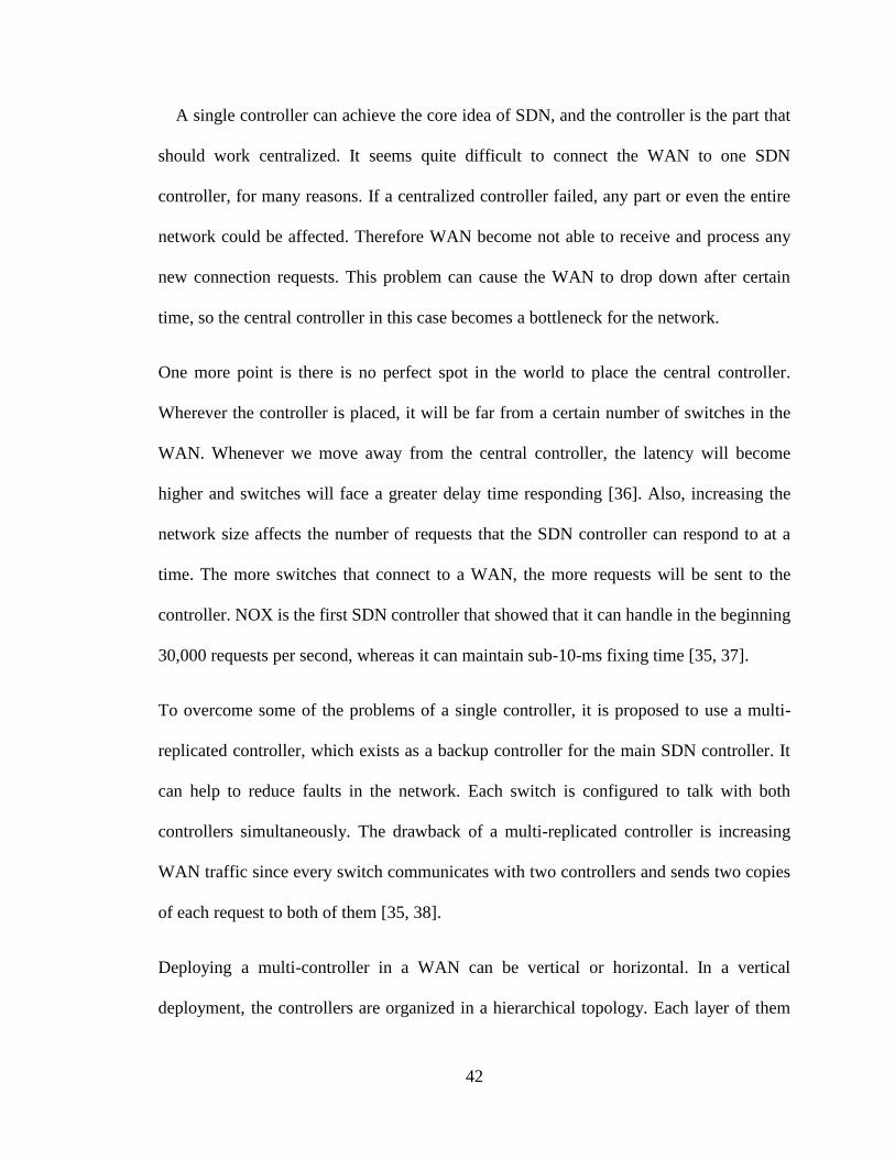
Figure 3-8 horizontal SDN controller deployment has two major components: network management
and zone manager. Also has three layers: a forwarding layer, an adaptation layer, and a
management layer [36] .................................................................................................................... 43
Figure 4-1 An infrastructure to integrate IP into an optical network [2] ....................................................... 48
Figure 4-2 The mechanism of integrating IP into optical metro networks. An IOTD is shown in the
green circle and two aggregation clusters in purple circles [2] ....................................................... 49

x
Figure 4-3 MAN SDN infrastructure ............................................................................................................ 52
Figure 4-4 Single domain SDN controller. Blue switches are edge switches and green switches are
interior switches .............................................................................................................................. 54
Figure 4-5 Two-level SDN controller ........................................................................................................... 55
Figure 4-6. MAN network controlled by SDN controllers. Grey connections are internal connections of
domains. Green connections are from edge switches to domain SDN controllers; Blue
connections are between edge domain switches; Red connections are fully loaded connections
between domains. ............................................................................................................................ 58
Figure 4-7 The mechanism of a connection request and the flow of data .................................................... 63
Figure 5-1 Network Schematic ...................................................................................................................... 66
Figure 5-2 Simulation flow chart .................................................................................................................. 71
Figure 5-3 Domain 1 Edge Switch 3 to Domain 2 Edge Switch 5 link traffic performance. ........................ 74
Figure 5-4 Domain 1 Edge Switch 4 to Domain 2 Edge Switch 1 link traffic performance. ........................ 74
Figure 5-5 Domain 2 Edge Switch 3 to Domain 3 Edge Switch 3 link traffic performance. ....................... 76
Figure 5-6 Domain 2 Edge Switch 4 to Domain 3 Edge Switch 5 link traffic performance. ........................ 76
Figure 5-7 Domain 3 Edge Switch 1 to Domain 4 Edge Switch 3 link traffic performance. ........................ 77
Figure 5-8 Domain 3 Edge Switch 2 to Domain 4 Edge Switch 1 link traffic performance. ........................ 77
Figure 5-9 Domain 4 Edge Switch 2 to Domain 1 Edge Switch 2 link traffic performance. ........................ 78
Figure 5-10 Network traffic performance. .................................................................................................... 79

xi
List of Tables
Table 5-1 Domain connection presented ....................................................................................................... 67
Table 5-2 Simulation update output .............................................................................................................. 72
xii
Glossary
API Application Program Interface
AR Aggregation Router
BGP Border Gateway Protocol
DWDM Dense Wavelength Division Multiplexing
EMS Element Management System
ES Ethernet Switch
FDDI Fiber Distributed Data Interface
IOTD Intelligent Optical Transport Domains
IP Internet Protocol
L2 Level Two Routing
L3 Level Three Routing
LAN Local Area Network
LSB Label Switched Path
MAC Media Access Control
MAN Metro Area Networks
MPOA Multi-Protocol Over ATM
NMS Network Management System
NOS Network Operating System
NV Network Virtualization
ONF Open Networking Foundation
OSI Open System Interconnected

xiii
OSPF Open Shortest Path First
PXC Photonics-Cross Connect
QoS Quality of Services
RWA Routing and Wavelength Assignment
SDN Software-defined networking
SDON Software-Defined Optical network
TCP Transmission Control Protocol
UCP Unified Control Plan
VoIP Voice Over IP
WAN Wide Area Networks

1
1 Chapter One: Introduction
The increasing numbers of Internet users, and the increasing popularity of cloud computing
and online applications have increased the need for high performance of Internet
connections, thus Internet design architecture has to evolve and enhance its power and
performance. In addition, the large growth of Internet traffic is requiring more and more
connection bandwidth [1].
The global network located in various locations around the world. These locations are
connected together by wide area networks (WANs) or metro area networks (MANs).
Network devices such as routers and switches do the traffic management functions. To
deliver high quality services to users, the network devices should work together for this
purpose; therefore, an optical network helps these devices to communicate and deliver data
from one to another. The Internet has changed the way of communication and transferring
data by using addresses. Internet protocol (IP) is the main communications protocols that
used in the Internet. Data that use IP are transferred in packet form. Packets are processed
in each network node that they pass into and then forwarded by a switch or router,
depending on the address, to the next node [2].
The cloud computing became an essential part of the Interne to deliver services to end users
that are cheaper, of high quality and trustworthy. Clouds have changed the form of transfer
data from purely packet-based to a flow-based form since the end user connects to the cloud
and exchanges data for computing purposes. Therefore, the existing Internet connection

2
will not be able to serve cloud traffic. Consequently, flexible and intelligent network
infrastructures are required to satisfy the growth of the Internet.
The IP protocol does a good job of serving end-to-end services on the Internet. Along with
the IP protocol, an optical network functions as a transport layer in the Internet, supporting
the expansion of Internet volume and providing low-cost bandwidth. Changing the Internet
structure to an optical network by using intelligent control and present optical agility will
make a big change in dealing with traffic management and flow of data. Therefore,
integrating the IP protocol into an optical network has become an essential issue to provide
guaranteed end-to-end services for cloud-based traffic flow. Software-defined networking
(SDN) promises to simplify the network infrastructure. Consequently, Using SDN to
integrate the IP protocol into optical networks will help to simplify the network. An SDN
controller can manage the flow of data from source to destination and monitor the traffic
in every way.
This work contribute to develop the existing design of integration IP into optical network
[2]. It replaces the controller of that design by two level SDN controller. The two level
SDN controller is existed but when it is used in the integration, it control the network better
than the previous design. The results of the simulation show the process of the connection
and the stability of the network from point of view of number of flow-based connection.
This thesis endeavors to show the effect of using SDN and to use an intelligent and
centralized SDN controller in integrating the IP protocol into optical networks to provide
an intelligent and centralized network. There are six chapters that develop the ideas of the
thesis. Chapter 1 is an introduction. Chapter 2 gives a wide view of computer networks and

3
it discusses the network structure layers and how an Internet works in these layers. Chapter
3 mainly spotlights the software-defined network and its properties. Also it presents an
explanation of how SDN can help to integrate the IP protocol in an optical network. Chapter
4 is the developing of the thesis idea which presents the network infrastructure of
integrating IP into optical networks and the mechanism of the integration. Chapter 5 is a
simulation and results. It discusses the simulation output and analyzes it. Chapter 6 is the
last chapter which is the conclusion and a discussion of future work.

4
2 Chapter Two: Computer network
2.1 Introduction
The computer network is the basis of today’s telecommunications technologies. The first
project in computer networking was in 1967 and it was called ARPANET. This was the
foundation of global communication. With today’s high technologies and the massive
amount of information that is stored in the cloud, network computing has become a part of
our life. This chapter shows various types of network architecture technology and how they
work together to provide users with the best services.
Chapter 2 reviews computer networking in three main sections. Section II discusses
network architecture and the seven network layers. We discuss internetworking technology
and how the various parts of the network are connected together in Section III. Section IV
is about layer-2 and layer-3.
2.2 Network Architecture
Computer networks usually consist of layers. The number of layers are variant from one
network model to another. Not only are the numbers of layers different, but also the
meanings and the purposes of each layer are disparate. The function of a layer is to provide
a service to the upper layer without informing the upper layer about how the given services
are executed. Layer X of Machine A can communicate directly with Layer X of Machine
B by passing through the lower layers of both machines. The conversation between layers
is restricted by protocol rules. Protocols are sets of instructions and agreements between
two machines so that they can communicate with each other. The Open System

5
Interconnected model (OSI) and Transmission Control Protocol/Internet Protocol model
(TCP/IP) are network architectures, which define the network architectures using two
different approaches.
The OSI model is structured in seven layers (shown in Figure 2-1). These layers are defined
well so that each one of them is doing certain jobs that don’t intersect the work of other
layers.
Figure 2-1 Network Layers Architecture
PRESENTATION
SESSION
TRANSPORT
NETWORK
DATA LINK
APPLICATION
PGYSICAL
APPLICATION
TRANSPORT
INTERNET
DATA LINK
OSI TCP/IP

6
Also the layers communicate using protocols, which help them to understand each other.
The layers of the OSI model are described briefly below.
The Application Layer is the seventh layer in the OSI model and the fourth layer
in TCP/IP. It is the interface between the user and the network. There are many protocols
that serve to access this network layer.
The Presentation layer is the sixth layer in the OSI model but this layer is merged
with the Application layer in the TCP/IP model. The function of the presentation layer is
to format data for the application layer. The presentation layer focuses on the structure of
the information in order to make the interior communication understandable.
The Session Layer is the fifth layer in the OSI model, but TCP/IP considers it as
another part of the presentation layer. This layer allows the host to start up a connection
session with another host and offer different services such as dialog control, token
management, and synchronization.
The Transport Layer is the third layer in the TCP/IP model and the fourth layer
in OSI. It has almost the same functions in both models. The transport layer receives data
from the session layer and divides it into units that can be delivered by the network. It also
passes the data to the next layer and ensures that the data arrives at the final destination
without errors.
The Network Layer in the OSI model roughly represents the Internet layer in the
TCP/IP model. The network layer is the third layer in OSI and the Internet is the second
layer in TCP/IP. The business of the network layer is controlling the underlying network

7
by generating and updating routing tables which are used to forward packets in the network.
In addition to that, it handles network connection and providing quality of services (QoS).
The Data Link Layer is the second layer in the TCP/IP model and comes before
the last layer in the OSI model. It formats the final shape of the data to make it ready to
send over the wire. The final shape is called a data frame; the size of the data frame is from
a couple of hundred to a couple of thousand bytes. Data link chooses the proper time, when
the channel is free, to send data without causing any collision. Also, it controls the speed
and the size of the data that can be handled on the recipient side.
The Physical layer is the first layer in the OSI model. It transmits a row of bits to
the network communications channel and makes sure that the bits are sent and received
correctly. The physical layer can be any of different kinds of communication, for example,
wired or wireless network, optical, or electrical network.
The object of the OSI or the TCP/IP model is to determine the layers and protocols which
work together to achieve the communication successfully. Therefore, when two
communication devices want to communicate; they should have at least one common
protocol in each layer to do so. Thus, the seven layers can be divided among different
communication devices and communication systems. A single device doesn’t have to
implements the seven layer’s protocol stacks at once [3, 4].
For simplicity, Global network architecture is divided into areas for easy control and
management. There are three general network categories: Local Area Network,
Metropolitan Area Network and Wide Area Network. Each of them has its own protocols,
architecture connections and communication devices.

8
2.2.1 Local Area Network
A Local Area Network (LAN) is a high speed network which covers a small area like a
home, computer lab, etc. The advantages of a LAN network are allowing computers to
share access between them and easily exchange files among users. LAN protocols work
on Layers 1 and 2. Examples of that are Ethernet, 100BaseT, and IEEE 802.3. A LAN can
transmit data between hosts in one of three various techniques: unicast, multicast, and
broadcast. Also, computers can be organized into different types of connections which are
called topologies, as shown in Figure 2-2. LAN topologies include bus, ring, star, and tree.
Each topology can handle certain types of protocols. Also some device could be used in
the connection to extend the connection. These devices, such as repeater, hubs, LAN
extenders, bridges and LAN switches interconnect and extend the LAN connection. A LAN
network interconnects distributed front-end systems, which are computers, workstations,
or services [5, 6].
Figure 2-2 Multiple LAN topology connected to the WAN [3]

9
2.2.2 Metropolitan Area Network
A Metropolitan Area Network (MAN) is a large computer network connection that is larger
than a LAN. It covers up to 40 km of LANs which are owned by different companies or
cities to provide services to a greater number of end users. One of the main purposes of a
MAN is to use a single switch to cover the whole city or area as shown in figure 2-3.
Figure 2-3 Metropolitan area network (MAN) [7]
2.2.3 Wide Area Network
A Wide Area Network (WAN) covers a large area like a country or an area even bigger
than a country. A WAN consists of nodes; the connection of these nodes is called a
communication subnet, or subnet. A subnet is the medium-sized network that is doing the

10
transmission and switching function for the WAN. These subnets are owed by various
companies which are Internet provider companies. The simplest way to imagine a WAN is
by considering it as a large LAN with some differences. These differences are related to
long wire connections, various higher performance forwarding devices, different
connecting technology and several protocols.
Figure 2-4 Point-to-Point WAN connections
Establishing single connection from host to host should be passed by a carrier network. A
Point-to-Point connection (Figure 2-4) is a single WAN connection that serves as a double
wire link between two hosts. A telephone company is the best example of a point-to-point
connection. This type of connection is costly, because it depends on the availability of
network bandwidth and the distance between two hosts.
Circuit Switching is a technique that shares the WAN. A communication link is reserved
by getting a request from a host to send data or to communicate with another host over a
WAN. The communication link is terminated once the communication is completed. For
example, Host A wants to communicate with Host B. A starts by sending a connection
request to B for a circuit switch connection. Routers between A and B reserve a fixed path

11
with a specific size of bandwidth until the conversation is finished; this is shown in Figure
2-5.
Figure 2-5 Circuit Switch Communication in a WAN [5]
A Packet switch in a WAN is another computer connection method that allows the host to
send data in packet form. All users share the same WAN connection infrastructure; this
leads to having cheaper communications compare with Point-to-Point communication. The
switch packet system transmits data as pieces. Each piece should have a certain data size
and source/destination addresses and is called a packet. These packets move through the
WAN using various paths depending on the network traffic, router connections and other
parameters between the source and the destination [5]

12
Figure 2-6 Different types of network that present internetworking [5]
2.3 Internetworking
Internetworking or an “internet” refers to a network interconnection which supports a host
to host connection to a delivery service. Layer 2 and 3 switches connect two or more LAN
networks; unfortunately, this is not enough for global network interconnection.
Internetworking tries to connect these entire limited networks of different types of network
to become either a MAN or WAN that can provide global connectivity. Figure 2-6 presents
a summary example of internetworking. It is clear from the figure that internetworking
consists of various kinds of small networks connected together such as Ethernet, Fiber
Distributed Data Interface (FDDI), and Token Ring. Every single technology network
connects to nodes, which are routers [5, 8, 9].

13
2.4 Routing and Switching
The network layer and the data link layer are focused on forwarding and switching
functions. The network layer is called the routing layer which is takes care of routing
packets all the way from source to destination. The path from source to destination contains
nodes. These nodes are a combination of routers and switches.
In contrast, the data link layer or switching layer works under the network layer. Mostly, it
connects routers and switching data to its final destinations. The data link layer switches
data according to its Media Access Control (MAC) address, but the Network forwards data
according to its IP address.
2.4.1 Network Layer
In this section we will briefly touch on issues that are related to the network layer and
routing. As discussed in the introduction, the data link layer connects an end user computer
on the level of a LAN. Therefore, to extend the network connection based on bridges and
switches to a global connection is not doable. The amount of data that is to be transmitted
is huge, which reduces the operation efficiency. Hence it is important to have a system that
can handle the global connectivity. The network layer can get over the limitation of the
data link layer.
The key aim of the network layer is to provide end-to-end connectivity. The host computer
interface has the ability to communicate with other host computers; this communication is
set up by the exchange of connection requests in the form of data frames. To do this
communication between hosts, it needs agreement instructions, implemented in both end
machines, which is known as a protocol. IP is the common protocol used today in most

14
communications devices. All hosts can communicate among each other by using IP
protocol. Achieving the main purpose of the network layer needs to involve many
significant protocol features. Addressing is a feature in which an IP address is assigned to
every network host. These IP address structures simplify the routing and forwarding
process. The second feature is routing; it has procedures to build the routing table which is
used to direct the data traffic to its final destination. The router should choose the
appropriate output port to direct the data traffic on the way to its final destination. This
happens, when the router uses protocols to have conversations with its destinations to
decide the best route from its point of view. One more characteristic is forwarding; it has a
close functionality to routing. Routing is deciding the best route for the packet to the next
router or to the final destination, but forwarding is the physical process of receiving a
packet then choosing the appropriate output port, then sending the packet by the route that
has been determined by the router [3, 4].
2.4.1.1 Control Plane of the network layer
Each layer has a control plane; the network layer control plane controls the routing
operation that is related to the routing process not forwarding data. The control plane
focuses on routing algorithms such as Open Shortest Path First (OSPF), Border Gateway
Protocol (BGP), etc. The routing algorithm is responsible for calculating the routing table,
which is used to determine the optimal path for forwarding packets [4].

15
Figure 2-7 Network Layer [10]
2.4.1.2 Path calculation
To help in calculating the routing path, routing algorithms prepare and maintain a routing
table. The content of the routing algorithm table counts on the routing algorithm used.
There are various algorithms to calculate the optimum route for data traffic to reach the

16
final destination. The basic standard function of routers is that every routing algorithm
should meet the criteria of delivering data traffic to reaches the final destination correctly
without losing any single bit. Unfortunately, not all traffic reaches its destination because
the network layer is naturally unreliable. Therefore, a good routing algorithm should make
sure that all traffic is directed to its final destination. The router can calculate the optimal
path according to one of the following optimization metrics; here are some examples of
routing algorithms:
Shortest Path: is a simple routing algorithm that calculates the shortest path
between source and destination and provides the routers with a full image of the
network. The shortest path could be the path that has fewer hops. In general, using
this metric is practical if the nodes present clearly and there is no physical change
in the network topology.
Highest available bandwidth: The link or path that has the highest bandwidth is
the one which would be chosen. For video, remote backup bandwidth is a very
essential factor for sending this kind of data so the whole path should have high and
stable bandwidth.
Lowest packet loss: is a routing algorithm that calculates the highest probability
of successful transmission. Voice Over IP (VoIP) applications require low packet
loss to provide good service.
Load balancing: This algorithm tries to balance the load in the network. If there is
a load in one of the paths, the load balancing algorithm distributes the load among
different paths to ensure the best connectivity.

17
Source Routing: is a technique that allowed the sender of a packet to define
partially or completely the rout of the packet from source to destination. It
explained in next subsection.
There is a long list of protocols (such as distance vector routing, link state routing,
lowest delay, etc.). These algorithms try to provide routing solutions through adding to
or removing links from the network that don’t satisfy the network requirement.
Therefore calculating the optimal path and sending large traffic to that path may cause
a huge load on that specific path, so the routing algorithm should calculate the optimal
paths and direct the data traffic through various optimal links to avoid traffic jams [3,
4, 5].
2.4.1.3 Source destination specified path
Additional to routing algorithms, source routing is a method that allows the sender host
of the packet to specify part of or all of a path of a packet that should travel through
network to reach its final destination. Source routing requires that the sender know the
structure of the network so it can specify hops or routers for the packet path. The packet
should carry its path addresses in the header and at each node or router the header
should be read and according to that address the packet will be forwarded. Loose
Source Routing is a source routing technique that permits the packet to carry an address
of particular routers it must pass through [11].

18
2.4.2 Switching
Switches are data link layer devices which principally perform Layer 2 functions. Layer 2
mainly focuses on control data flow, handles transmission errors, and provides physical
addressing. A switch is a simple forwarding device that works based on the MAC address
that is handled in the frame head. When the switch gets frames, it starts with reading the
MAC address header. Based on that MAC address; the switch decides to forward the frame
to its destination. Layer 2 protocol is a low level protocol, so the switch cannot understand
the upper-layer information such as the IP address. Knowing the destination address is
required to help in forwarding the frame toward the destination. Therefore Layer 2 protocol
makes the forwarding process easier and faster in Layer 2. Switches are very helpful in
connecting two or more networks together, which leads to diminishing the network traffic
by forwarding the data traffic among different paths. Connecting different parts of the
network by using switches helps to create multi-paths between network segments. LAN
network effectiveness could be extended and the LAN could be connected to another LAN
network through switch devices [4].
There are two kinds of switches, Layer 2 switches and Layer 3 switches, which have
different functionality.
2.4.2.1 Layer 2 Switches
Layer 2 switch, also called bridges, work to join LAN segments on the level of Layer 2.
The major difference between a Layer 2 switch and a bridge is that the switch has hardware
to make sure that all ports are active at the same time. For instance, in Figure 2-8, the Layer
2 switch is connected to four stations. Station A is connected to Port 1, B is connected to
Port 2, C is connected to Port 3, D is connected to Port 4. Let us assume that A wants to

19
communicate with B, and C wants to communicate with D. if we replace the Layer 2 switch
with a bridge, a single CPU bridge will pick up frames from A and C sequentially and
forward them to suitable output ports. Notice that the traffic from A to B and C to D is
independent, but the bridge processes them sequentially. Therefore this technique in that
scenario is not inefficient. By using a Layer 2 switch, the hardware of the switch is capable
of forwarding the traffic from A to B and from C to D in parallel, which means the switch
can forward many frames from port to port simultaneously.
A switch works base on Media Access Control addresses, where each port has a unique
MAC address, so a multiport switch forwards frames according to its MAC address. A
multiport switch creates a lookup table which contains each port number and its related
MAC addresses.
Figure 2-8 Layer 2 switch with router [12]

20
Additionally to that, the switch can update the lookup table by checking the MAC address
and the port number of the receiving frame and match them up using the lookup table. If
the new MAC address is not available in the lookup table, the switch should add it;
otherwise, the switch could not decide to forward the packet. The weakness of the Layer 2
switches is that they can’t connect two different IP stations. For example, A and B are part
of same IP subnet as long as C and D are part of a different IP subnet. When A and B or C
and D communicate between each other, that is fine for a Layer 2 switch because they
belong to the same subnet but Layer cannot interconnect A with C because A and C belong
to two different subnets, which means they have different IP addresses. In this case, the
Layer 2 switch is inadequate; it needs an IP router [3, 12, 13].
2.4.2.2 Layer 3 Switch
Layer 3 switching has been called fast IP routing via hardware or others have called it
Multi-Protocol over ATM (MPOA) Layer 3 router. Layer 2 switches can handle simple
traffic between LANs as shown in Figure 2-9. To improving Layer 2 switch functionality,
we need a router which has more functionality than a Layer 2 switch, but it is slower if we
compare the speed of the forwarding process. Layer 2 switches work on the Ethernet MAC
frame. This algorithm of Layer 2 is defined well on the hardware. It is not easy to develop
the algorithm of Layer 3 protocol in a Layer 2 switch since Layer 3 has various protocols
like IP, IPX, etc. Also, the Layer 3 forwarding algorithm is more complex than the Layer
2 algorithm.

21
A Layer 3 switch is a modified version of a Layer 2 switch with limitations, which performs
IP protocol. IP protocol is very common among Layer 3 protocols, and most of the
communication devices handling IP protocol. Therefore a Layer 3 switch performs IP
protocol only, which is implemented in the hardware and using software of Layer 2
protocols. The second feature of a Layer 3 switch, which increases the complexity, is the
IP header length. IP header length is not stable because it has an option for adding data so
this affects the IP header length. For simplicity, most communication devices neglect this
option of an IP header. Therefore Layer 2 IP protocol assumes the IP header is a constant
length. Layer 3 can perform as router, but its forwarding function is done by the hardware.
One more point is that Layer 3 switches can’t replace routers in some spots of the network.
Figure 2-9 Layer 2 and Layer 3 switch [12]

22
For example, a router is an essential part when connecting a LAN to a WAN. Also routers
need to provide Layer 3 switches by the routing table and Layer 2 switches need to pass
packets to a router, which should be send over a WAN. A Layer 2 switch works perfectly
in the workgroup and the backbone network, nevertheless, it can’t take the place of a router
at the edge of the WAN since a router handles more functions and protocols than a Layer
3 switch [3, 12].
2.5 Conclusion
A computer network consists of seven layers in the OSI model, and each layer do can talk
directly to the layer above or below it. For simplicity, the network is divided to three areas:
LAN, MAN, and WAN. Internetworking technology shows the technique that connects the
three different parts of the network. This thesis concentrates on Layer 2 and Layer 3 which
are the data link layer and the network layer.

23
3 Chapter Three: Software-Defined Networks
3.1 Introduction
Our industry has come a long way. Yet after several waves of innovation, we have
yet to push the boundaries of Software-Defined Network (SDN’s). While the current
technology enable us to create top-of-the-line communication networks, we still lack in
offering a simplified network architecture, implementation, controlling and management,
in which lead to the sought after increase in network dimension and complexity. In the
ideal world it is possible to separate between an application or service and the core network
infrastructure but this is always not possible.
The methodology of this process is illustrated in this report. While in the second
section, the report illustrates the need for modelling a better way of integrating the network
architecture with a simplified process of implementation. To have a good application
performance, the core network must be able to provide application process with a reliable
service For the purpose of definition, a reliable process of application is when the core
network is able to properly handle a significant amount of traffic in terms of the processing
demands and supplies within the application network [14]. An effective network control
plane needs to have the ability to control and direct the traffic that has been generated by
applications, while it works to discover and configure the need resources in the network
simultaneously. In traditional network plans, the network control plan is attached to the
network data plan, thereby making it less reliable. To review, a data network plan includes
the actual devices, such as Ethernet switches and routers, which move data traffic from
node to node [15]. A current technological advances enables the application of certain

24
methods that would allow for using “programmable networks” as a resolution in assisting
network development. One such example, and one that currently receives positive reviews
from the industry, is the Software-Defined Network (SDN) [16]. For the moment however,
the SDN is used almost exclusively with computer networks to assist in solving the
complexity of the network and in simplifying the network architecture.
3.2 Software-Defined Network (SDN)
3.2.1 Definition
A general definition of Software-Defined Network is that it is a new network
concept that separates the control plane from data plane which then enables the
centralization of a programmable control plan. A SDN is simply a process that is able to
separate the control plan, from the control decision and from the forwarding hardware [16].
The Open Networking Foundation also defines the process as a product unique to the SDN
architecture, which enables the control and data planes to be decoupled with the network
intelligence and state are logically centralized, and the underlying network infrastructure
is abstracted from the application.” [17].
3.2.2 The SDN architecture
Computer networks are a communication networks between computers which allow for the
data to transfer from host to host or from computer user to another computer user. The
basic networking hardware within computer networks are routers, switches, and various
middle boxes and links. These network devices handle various and complex protocols
which enable the system to control the data traffic in every node in the network. As
illustrated in Figure (3-1 a), the general architecture of the SDN starts from top application,

25
control plan and forwarding/switching, which is data plan. Additionally, as illustrated in
Figure (3-1 b), the regular network design without SDN translates into integrating the
control plane and data plane together.
The SDN includes four main distinguishing properties that set it apart from others:
The separation of the control plane and data plane: This is the main
distinguishing factor that sets the SDN apart. This separation of the control plane
and the data plane allows the centralization and programming of the network
controllers and data planes. It enables the network to easily control and manage the
virtualized resources directly via operators and/or service providers [18]. The
Figure 3-1 Network architectures: A) SDN implemented with API between application and the SDN controller; B)
Regular network architecture with GMPLS control plane with integrated control and switching on network elements
with API [14].

26
network protocol usually consists of three network planes: data, control, and
management. The Data Plane, as explained above, consists of all the messages or
data generated by the user’s computer. Sending these data from host to host requires
route calculations, which are usually processed through the network hardware
before it begins to start transferring the data. Level three router (L3) protocols are
part of calculating the pathway. By applying one of L3 protocol such as Open
Shortest Path First or IP or one of Level two protocol (L2), after that the pathway is
then made available to the control plane. This operation requires sending and
receiving massages to setup the communication called “control messages”. The
second plane is Network management which is considered more essential in bigger
networks rather than smaller networks. The Network management is responsible for
tracking the traffic statistics and the networking devices. The last distinguishing
property of the SDN network is the data plane which holds the network’s hardware
devices. Routers and switches, which are part of data plane, are responsible for
forwarding the data by using a forwarding table which is then supplied by the control
plane [19]. Again, the ability of the control plane to be separated from the data plane
to allow for more flexibility and better monitoring within the network is one of the
most important qualities of the SDN.
The ability to centralize the control plane and track the network: the early
design of the communication system was based on centralization and placed it in
one central location. The main concern for systems that were set-up like this was
that in the event of a technical breach in a given telecommunications center, all

27
protected data are put in great risk. Therefore, they changed the network
architecture to be based vastly on a decentralized architecture. This separation and
decentralization in design allows the packet to reach it final database- destination
regardless of a technical breach such as when a routers malfunctions. The concept
was based on the idea of entirely distributing the control plane and the data plans
over the network to save some data center. This network design concept is not new
nor is it unique to SDN. The idea of distributing the network control was actually
the same principle behind the design of the Internet. While, separating the
centralized network was originally seen as problematic when applied to network
management. Today, however, with the new technologies, researches and needs of
increasing the capability; telecommunication companies started began to re-vist the
idea of abandoning centralized network architecture. As new technology was made
available [19]. Google was one of the first of many companies to use SDN to
interconnect its data centers over the world [20]. They built B4 network, which is a
great example of a SDN network, since they noticed that they could not reach a
level of scale that the network could suitably handle while the fault tolerance
became costly due to both its inefficiency and, time spent on the current network
by using Wide Area Network [21]. To avoid further inefficiencies, Google built the
B4 network to have both a centralized control and an improved network
management for it’s numerous data center around the world. As previously
mentioned, the centralization of controller adapted networks can be problematic.
Consequently with the SDN architecture, it enables the system to connect more than

28
one controller to each switch, so that if any technical failure happens within a
controller, a backup controller is able to regain the process [16].
Author Kandoo, however, presents the SDN concept in different view. In his
previous work, he was able to reduce the load in the controllers by implementing a
control plane as a hierarchy topology. They then divided the controllers into two
categories: local controllers and global controllers.
The local controllers focus on local applications while a global controller controls
the local controllers and a centralized network state. The local controllers
communicate with global controllers for decisions that require centralized network
decision. This leads to a data load decrease, which then enables the global
controllers to respond faster to the data plan request processed by the local
controllers [16, 22].
Figure 3-2 Layer view of networking functionality. [19]
29
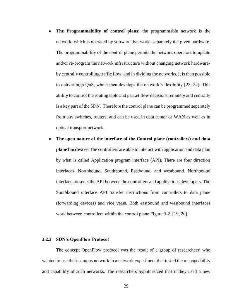
The Programmability of control plans: the programmable network is the
network, which is operated by software that works separately the given hardware.
The programmability of the control plane permits the network operators to update
and/or re-program the network infrastructure without changing network hardware-
by centrally controlling traffic flow, and in dividing the networks, it is then possible
to deliver high QoS, which then develops the network’s flexibility [23, 24]. This
ability to control the routing table and packet flow decisions remotely and centrally
is a key part of the SDN. Therefore the control plane can be programmed separately
from any switches, routers, and can be used in data center or WAN as well as in
optical transport network.
The open nature of the interface of the Control plane (controllers) and data
plane hardware: The controllers are able to interact with application and data plan
by what is called Application program interface (API). There are four direction
interfaces. Northbound, Southbound, Eastbound, and westbound. Northbound
interface presents the API between the controllers and applications developers. The
Southbound interface API transfer instructions from controllers to data plane
(forwarding devices) and vice versa. Both eastbound and westbound interfaces
work between controllers within the control plane Figure 3-2. [19, 20].
3.2.3 SDN’s OpenFlow Protocol
The concept OpenFlow protocol was the result of a group of researchers; who
wanted to use their campus network in a network experiment that tested the manageability
and capability of such networks. The researchers hypothesized that if they used a new

30
switch that virtually programmable, they would then be able to carry out the test without
affecting the network configuration [18].
This is why the concept of the SDN always linked to OpenFlow, which is the protocol
typically used within the SDN network. OpenFlow is a protocol allowed accessing to the
data plan devises (such as Router, Switches, etc...) over network; this definition is brought
by Open Networking Foundation (ONF) [25]. Of the OpenFlow process requires the use
of a virtualization machine which then allows for the programming of the network devices
[26]. The OpenFlow process also requires a unified control plan (UCP) and a design for
packet and circuit network. OpenFlow supports the decoupling between the data plan and
control plan and also handling the data flow. For the purpose of this exercise, we define
Data flow as the packet flow which is the combination of any layer 2, 3, 4 headers or circuit
flow layer 0, 1. This data flow can generate a simple flow that fits both packet and circuit
flow. Therefore, OpenFlow represents a joint platform for the control of the underlying
network device, which switching flows of data various granularity. However; routers,
switches and managements could also be externally configured for programmability [27].
3.2.4 Network Virtualization
The expression Network Virtualization (NV) has been defined as separate from the
underlying network and the network hardware. Author, M. Rouse defined the NV as “a
method of combining the available resources in a network by splitting up the available
bandwidth into channels, each of which is independent from the others, and each of which
can be assigned (or reassigned) to a particular server or device in real time”. An NV
progress can manage various tasks automatically such as efficiency, administrator’s job,
and productivity. It aims to provide an optimized speed, reliability, flexibility, scalability,

31
and security. It is therefore seen as a simplified network. In reality however, the NV is a
complex set of processes. One physical device can manage all files, folders, storages, etc…
centrally. Also it can add or remove drivers and combine and/or share storages with in the
servers [28].
The virtualization of most commands means that it is possible to emulate a
hardware platform by using such software. A good example for that are hardware such as
the router, switch, server, and storage devise. It is allowed to separate all functionality from
the hardware emulator and works as the hardware devise itself. For instance, there is a
hardware computer handling it, this hardware devise can work to support more than one
virtual machine at the same time. This flexible technique allowed separating the hardware
capability between virtual machines according to their needs [29].
VN is an overlay, which is virtual tunnel not a physical connection between two
domains in the network. VN uses the physical network to create tunnels between domains
and connect them together. The advantage of VN is that help the network administrator to
create virtual connection instead of using wired connection to connect two domains which
is going to be on the top of the present network.
Generally SDN and VN are similar concepts. But when one look at the properties of
a SDN, which is separating the plan control form the data control, we notice that SDN
changes the physical network structure. Control plane indeed is outside device that monitor
and control the network. While VN is implemented morphologically in the traditional
network without changing the network physically [30].

32
3.3 Why use SDN?
Network consists of nodes connected together to achieve the goal of the network
reliability in transferring data from host to host within the network. With network
expansion and increasing the number of users; a network needs a structure that is simple,
smart and intelligent. SDN creates a pathway for existing networks to operate in smarter
and more efficient manner. This efficiency helps to monitor the network and while making
it easier to control and observe. In this section, this research exercise will compare between
the regular network and the SDN network from different point of view and showing that
why we need SDN.
3.3.1 Previously Used Networks
Traditional networks consist of devices that handle both control plane and data
plane. The control plane is integrated in the data plane which are both located in the
network node such as routers or switches. They work in a systematic way; the tasks of
control plane are configuring the node and calculate the routing paths for forwarding data.
When the routing table path has prepared, it should be given to the data plan, which is
located in the same device. After the packets in the data plan will forward according to the
routing table that was generated by control plane. One disadvantage of such a network
architecture is the inability of the network operator to expand the network with increased
traffic. The only way to address this issue is by changing the device configuration which
will, unfortunately, affect the entire network [15]. Another disadvantage is when the data
plan and control plane is able to alter each other’s state as they are both located in the same
unit. When there is congestion in the network, the data plane tries to mitigate the problem

33
by forwarding packets as fast as it can while the control plane runs at full capacity, at the
same time ,to find the optimal path. In this situation both data plan and control plan work
at the maximum ability which triggers technological failures within the system.
3.3.2 The SDN Network
SDN was specifically developed to address the problem of having a single location
for both the control plane and the data plane. After separating the control plane and moved
it to centralized controller, the SDN now controls the forwarding devices by network
operating system (NOS) jointly with API. API function is to collect information for
Figure 3-3. SDN structure [43]

34
controllers from data plane. Figure 3-3 shows the relationship between the control planes,
API, and data plane. The SDN controller has a more comprehensive view for the network
which help to improve forwarding management and offering scalability and flexibility for
the user-service.
In a SDN network, when a host wants to send a flow of data using such a network, the host
should start sending several packs to a given switch [15].
When the first packet arrives at the switch, it reads the header then looks for
instructions of a SDN that matches the header information.
If the header information matches one of the SDN instructions, the switch then
proceeds to process the flow of data and send it the next switch or end user.
If the packet header information doesn't match any one of the SDN instructions, the
switch sends the packet to the centralized controller in secure path. By using
southbound and API the switch can communicate with control plane, so the
centralized controller can add, delete, update the data flow particularly for this and
in advance for next data flow that have the same header instructions.
After this process the centralized controller should process the routing algorithm,
enhance the forwarding table, and send those enhancements to all forwarding table
of the switches which are connected to that central controller.
At the end of the process, the forwarding table of that switches will be updated and
the packet is sent its final destination
35
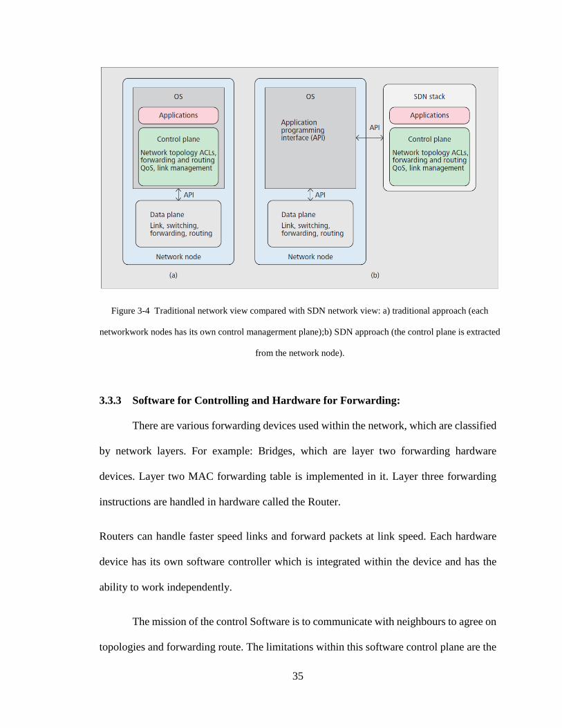
3.3.3 Software for Controlling and Hardware for Forwarding:
There are various forwarding devices used within the network, which are classified
by network layers. For example: Bridges, which are layer two forwarding hardware
devices. Layer two MAC forwarding table is implemented in it. Layer three forwarding
instructions are handled in hardware called the Router.
Routers can handle faster speed links and forward packets at link speed. Each hardware
device has its own software controller which is integrated within the device and has the
ability to work independently.
The mission of the control Software is to communicate with neighbours to agree on
topologies and forwarding route. The limitations within this software control plane are the
Figure 3-4 Traditional network view compared with SDN network view: a) traditional approach (each
networkwork nodes has its own control managerment plane);b) SDN approach (the control plane is extracted
from the network node).

36
centralization that can distribute the routing instructions among the network devices [31].
To simplify the processes, the forwarding responsibilities has been done by layer two and
three network devices, those network devices’ software manage the control plan
individually, and the devices' configuration is set up by configuration and management
interfaces. SDN gives the opportunity to disposal this weakness of the network and
simplify the network which let us to move forward to next network generation [31].
3.3.4 Network Simplification
With Network devices becoming more intelligent, it has become possible to integrate inside
the network devices. While this has led to additional complexities within the device’s
design and network. It has also enabled it to handle more functions within hardware. This
process has allowed for the simplifications within a given network but at the same time it
introduces additional complexities for the device, in part due to the problematic
connections between handling packets in hardware versus software [31]. This fact
illustrates that the procedures of simplifying the devices is not efficient enough. Network
simplification must be improved in terms of improving in the network management of these
devices. Shenker states that SDN is the key in network simplification for the next
generations of networks [32].
3.3.5 Separation between Device and control
The core of the network is the control software, which decides the optimal route and
is in charge with communicating with neighbors. By moving the intelligent core off the
network’s hardware device and by keep it in centralized within the computer‘s resource,

37
this implements the idea of SDN. The software controller will then have a wide seeing for
the entire network and also this helps to take optimal decisions. A SDN separates the
network to three categories: 1) Forwarding that the hardware device handles the forwarding
table which is implemented entirely as before and forward the data flow. 2) A Centralized
software controller has a whole network image which help to take optimal decisions for
forwarding route. The simple programing software, which is available in each network
device, will be configured by the centralized software controller. 3) Application is the
platform that is above the controllers. It is content higher-level functions and also takes
part in management and packet forwarding and distribution within the network [31].
3.4 Using SDN’s for Optical Networks
The concept of Software-Defined network can also be applied for an optical network,
which can also be called Software-Defined Optical network (SDON). Integrating a SDN
with OpenFlow within an optical network is key to implementing multiple network
technologies and in enhancing the traffic data flow. Also to use centralized controller in
optical transport network, it makes the interaction between packet and circuit-switch
network simpler [16].
The advantages of integrating SDN and OpenFlow standard in optical transport network:
Enhance the control and network management of optical transport network.
Adding one or more external control and management system easily.
Propagating extra services by using Virtualization and SDN.

38
The feature of SDN and OpenFlow will be applied in optical network in a way that enables
the network controller the programming property. The SDN supports the application in
achieving improved visibility and control for connections link that handling data, also
watching and protecting the network’s connection links [33]. Integrating an application
interface to support application-driven of the centralized network management system
(NMS) of current optical network and circuit or packet switch, can be enhanced the whole
network. This enhancement came from the controlling of application to the network and
the big view of the network that application has.
There are two management systems used in optical network, Element Management System
(EMS), and (NMS). The management system operators should design the circuit and set
up the network elements configuration.
There has been some development in the implementation of optical network management
by backing an energetic control plan distributed to speed up the circuit design process and
improve provisioning time. Some optical network use general MPLS (GMPLS), which is
dynamic control plan along with integrating switching plane and control. By implementing
Figure 3-5 OpenFlow control Structure [27]
39
a
API in the northbound interface of the EMS/NMS will help the application layer to get
more controlling on the network.
While each system has its limitations, the limitations of network design can be
known by the overall flexibility. The limitation of an optical network control plan, which
is located in the network device, is the number of functions that controller can access.
3.4.1 OpenFlow protocol and SDON controller in optical Network
The main points of SDN are to decouple the control plan from data plane and make
a centralization control plan for the network. OpenFlow in figure 3-5 is one of the best
protocols can achieve the view of SDON. To use OpenFlow protocol in optical network
need to use OpenFlow switch. The OpenFlow switch consists of a group of tables and flow
tables which are then used for forwarding data and OpenFlow channel that connects the
OpenFlow switch to a centralized controller. The communication between the OpenFlow
switch and controller is via OpenFlow protocol [25]. Each OpenFlow controller connected
to multiple OpenFlow switches; it connected them through secure channel, which is
OpenFlow channel. The OpenFlow channel connects exactly the controller such as NOX,
POX, and FloodLight to the OpenFlow switch. The OpenFlow protocol is in charge of the
signaling between the controller and the switches.
Packets in the SDON network are processed in a systematic way. When packets
arrive, the OpenFlow switch is then forwarded by the OpenFlow switch according to the
flow table, which is assigned by the controller. If the packet header doesn’t match one of
the flow table instructions, the OpenFlow switch sends the packet to the controller. The
controller will then decides to either to drop the packet or to add new instruction in the

40
flow table of the OpenFlow switches. This update helps the OpenFlow switches to forward
any packet that handle the same header in future.
By looking deep in optical nodes as Lei Liu illustrated in their paper on the optimal design
of SDON. They introduced virtual Ethernet interface (veths) in figure 3-6 (a) which is
compatible to a physical interface of the photonics-cross connect (PXC). This technique
allowed controller to monitor the OpenFlow switch, and control the optical light paths thru
using the OpenFlow protocol. The complete design system, which consist of OpenFlow
switches and their corresponding PXC, is called OpenFlow-enabled PXC (OF-PXC)
shown in figure 3-6 (b). In this exercise the OF-PXC is controlled by the centralized
controller. When the packet header arrives to the controller, the controller decides the best
routing and wavelength assignment (RWA) according to the controller experience in the
network. Should the process succeed, the controller then sends the new instruction to all
OpenFlow switches and update their flow table or data plan [26].
3.5 Metropolitan and Wide Area Software-Defined Network
SDN used to be focused on the data center and it created huge changes, but recently it
expanded out of the data center to the LAN, MAN, and WAN to enhance network
performance. Integrating SDN into MANs and WANs has attracted researchers’ and
vendors’ attention because SDN has presented strong flexibility and programmability of
network management. In the other hand, managing WANs has become more difficult and
complicated because of various protocols, different Internet provider, etc. Thus, SDN can
help simplify WAN management and alleviate problems [34].
a
K
a
n
d
o
o
l
o
o
k
e
d
t
o
t
h
e
S
D
N
c
o
a

41
SDN architecture in a data center is designed as a single controller that controls all of the
data center traffic. In contrast, a WAN has wide network connections that connect over
users and handle global Internet traffic. Each hop in a WAN can be considered as a
controller, which could be far away from the local switches. This leads to increased
communication latency between a switch and a controller [35]. Thus, many researchers
don’t prefer to use a single controller in a WAN because of the distance between switches
and the controller. Therefore a multi-controller SDN solution has been proposed; Google’s
B4 is one of the biggest SDN controller distributions, as discussed in the SDN architecture
section. Multi-control SDN is proposed in two different categories; two-level hierarchy
control and a distributed controller network. Each of them has its specific features.
B A A
K
a
n
d
o
o
l
o
o
k
e
d
t
o
t
Figure 3-6 (a) The Desiggn of phsiycal interface of PXC to virtual Ethernate Interface of OpenFlow switch.(b) Design of
an OF-PXC [26]
42
A single controller can achieve the core idea of SDN, and the controller is the part that
should work centralized. It seems quite difficult to connect the WAN to one SDN
controller, for many reasons. If a centralized controller failed, any part or even the entire
network could be affected. Therefore WAN become not able to receive and process any
new connection requests. This problem can cause the WAN to drop down after certain
time, so the central controller in this case becomes a bottleneck for the network.
One more point is there is no perfect spot in the world to place the central controller.
Wherever the controller is placed, it will be far from a certain number of switches in the
WAN. Whenever we move away from the central controller, the latency will become
higher and switches will face a greater delay time responding [36]. Also, increasing the
network size affects the number of requests that the SDN controller can respond to at a
time. The more switches that connect to a WAN, the more requests will be sent to the
controller. NOX is the first SDN controller that showed that it can handle in the beginning
30,000 requests per second, whereas it can maintain sub-10-ms fixing time [35, 37].
To overcome some of the problems of a single controller, it is proposed to use a multi-
replicated controller, which exists as a backup controller for the main SDN controller. It
can help to reduce faults in the network. Each switch is configured to talk with both
controllers simultaneously. The drawback of a multi-replicated controller is increasing
WAN traffic since every switch communicates with two controllers and sends two copies
of each request to both of them [35, 38].
Deploying a multi-controller in a WAN can be vertical or horizontal. In a vertical
deployment, the controllers are organized in a hierarchical topology. Each layer of them
43
has certain responsibilities. Kandoo is an example of hierarchical deployment [22]. On the
other hand, in horizontal controller deployment, as shown in Figure 3-7, every controller
is responsible for a part of the network and each controller has identical tasks and does the
same job separately. HyperFlow is a horizontal controller example using NOX controllers.
Controllers are connected to part of a wide network and connected to each other by the
HyperFlow controller application. This lets the controller have a complete view of the
network. All controllers do the same job [39].
Figure 3-7 horizontal SDN controller deployment has two major components: network management and
zone manager. Also has three layers: a forwarding layer, an adaptation layer, and a management layer [36]

44
3.6 Conclusion
SDN promises to solve the complexity of the network by decoupling the control from the
forwarding process. This is clearly shown in how the SDN architecture and the OpenFlow
protocol can simplify the core of the network. Also it brings dramatic change for network
software and hardware devices. SDN is implemented in the optical network and recently it
has been integrated in MAN and WAN networks as well.

45
4 Chapter Four: Using SDN to integrate IP into
optical networks
4.1 Introduction
Software-defined networks exist to improve the network traffic and promise to provide
reliable services. On the other side, MAN and WAN need improvement so they can handle
the data flow of cloud computing. Using SDN in MAN and WAN networks is a step
forward to the enhancement of internet connectivity and to providing a smooth flow of
data. Connecting to the Internet has become an essential part of our daily lives. Using the
services that cloud computing provides to the user is huge, too. Additionally to that, new
smart projects such as the Internet of Everything, etc… These large amounts of data have
brought about a new concept, which is the flow of data. Flow-based communication is a
flow of data transmits from host to host. For example, an active sensor keeps sending data
to cloud computing or a data center. Therefore the current WAN and MAN will not be
sufficient for serving cloud computing.
The IP protocol is the most popular protocol used for host-to-host connectivity. This
means that it must be considered as a part of the solution at this time. Also optical express
is an outstanding technology which performs as the transport layer of the Internet in WANs
and MANs. As a consequence of desperately increasing the MAN scope and decreasing
the bandwidth cost, an optical network link functions as a static configuration for
technician, operator, and for economical purposes [40]. Using optical networks along with
SDN could help to manage the increasing data traffic and flow pattern in a new form. In

46
addition to that integrating IP protocol into a MAN optical network will offer assured end-
to-end connectivity for cloud-based traffic flows, which require intelligent and flexible
bandwidth.
This chapter discusses how SDN can be used to integrate IP protocol into optical
networks for MANs with a unified controller that calculates the optimal path from source
to destination for each flow of data. This work is built on the work of Wei and Trevor in
their paper, “An infrastructure with a unified network to provide flexible and intelligent
bandwidth on demand for cloud computing” [2].
This chapter is covered in two parts, Section I is the literature review of infrastructure
with a unified network and the objective of that work and Section II discusses the
development to that work and the impacts of using SDN to integrate the IP protocol into
an optical network.
4.2 Literature review of integrating IP into optical metro network
infrastructure and controllers
This work was proposed for integrating IP in a MAN optical network and the aim was to
guarantee end-to-end service in bandwidth, delay, and delay variation for flow-based
network traffic. This paper was divided into two parts, an infrastructure to integrate IP into
optical networks and a controller plan.
4.2.1 An infrastructure to integrate IP into MAN optical networks
A MAN optical network consists of interconnected intelligent optical transport domains
(IOTD). IOTD is a group of optical switches that were connected together as shown in
Figure 4-1. Optical switches consist of two layers, an electrical layer and a photonic layer.

47
The electrical layer is separated into two categories: a basic forwarding plane and a
distributed controlling plane. The forwarding plane passes a flow of data from source to
destination. On the other hand, the controller plane responsibilities are directing the flow-
based traffic inside the IOTD, distributing the signal to set up or release a dynamic optical
connection, calculate the routing path-fiber-wavelength-time slot for a new connection, and
calibrate with an inter-domain control plane to set up a connection path between IOTDs as
part of an end-to-end optical connection.
The IP router is modified and new features are required to be added. It is located in the
distributed inter-domain plane in the optical network. The characteristics of an IP router
are:
The IP router has features that allow it to offer customized network protocol,
specify the connection path, and manage the network.
The IP router supports the end-to-end global connectivity in optical networks for
MAN, so this new design helps to release the difficulty of operating the network
and increasing the network sizes.
The IP router path calculation helps the network to recover fast from any failures
by recalculating in each IOTD and insuring a new path.
The IP router is located in the control plane for controlling and calculating the
routing path which helps the forwarding plane to put more effort into the
forwarding process.
The mechanism of this system begins to aggregate the traffic from hosts in two aggregation
clusters on both side of the IOTD edge. Each side of the edge contains an Ethernet switch
(ES) and aggregation router (AR).

48
Figure 4-1 An infrastructure to integrate IP into an optical network [2]
The Ethernet switch functions as a node for collecting IP traffic from the hosts and passing
it to the IOTD in the MAN and at the same time, it works in the opposite direction by
getting the IP traffic from the IOTD and distributing it to the hosts. Each Ethernet switch
is linked to two optical switches in the MAN for the purpose of load balancing in the
forwarding plane. Each optical switch is connected to AS which controls the IP traffic
between the Ethernet switch in the aggregation cluster and the optical switch in the IOTD
in the MAN, Figure 4-2.

49
The Ethernet switch uses the OpenFlow protocol concept for directing the traffic data flow.
When a connection is set up, the data flow should be identified for all of the Ethernet
switches and optical switches in the whole path. IR signal is responsible of ARs and it is
known as the IP signal and Ethernet signal. Every AR is provided an optical link to every
IR in the IOTD and an optical link to every Ethernet switch so they can cooperate to assign
the channel by IP signaling and Ethernet signaling. Two ARs in each aggregation cluster
help to balance the load in the cluster.
Figure 4-2 The mechanism of integrating IP into optical metro networks. An IOTD is shown in the green
circle and two aggregation clusters in purple circles [2]
4.2.2 Control plan to integrate IP in optical networks
The control plane of this structure is a distributed control plane which can achieve the
objective of the idea. A distributed control plane can provide flexible and intelligent end-
to-end bandwidth; also it is more practical for scaling up the network. The control consists

50
of two classes, as shown in Figure 4-1, an intra-domain sub-layer to control the signaling
in the IOTD, and an inter-domain corresponding to IP router signaling that controls the
data plan of the forwarding plane. The transmitted data should contain a control flow
reference number in the header. The flow reference number contains the path
identifications such as the source destination IP, the source and destination Ethernet switch
ID, card number and port number.
This infrastructure presents a technique to integrate IP into an optical MAN network for
supporting flexible and intelligent bandwidth for cloud computing. With a different control
plane, the network can be configured and direct traffic from the source to the destination.
An optical switch receives orders from the data plane to direct the flow of data and gets
orders from the distributed control plane for directing the enterer traffic of the IOTD. The
IP router controls the forwarding plane and calculates the path for each flow of data.
Therefore IP has been integrated in the optical network by the IP router and forwarding by
an optical switch in the MAN network.
4.3 Integrating the IP protocol into optical networks by using SDN
We developed the idea of the previous paper by using a Software-defined network to
integrate IP into an optical network to achieve the same goals which were flexible and
intelligent bandwidth. The three layers of SDN, control plane, forwarding plane and
application, can integrate IP in a MAN of optical network or in a WAN but that needs to
scale up the SDN network as shown in Chapter 3. Multiple SDN controllers can be used
for each MAN domain to control the edges’ optical switches by providing them with the
information of flow of data that is going to pass through them and at the same time they
can monitor the link bandwidth between domains.

51
Using SDN as a new technology helps to keep the use of IP protocol as an end-to-end
transmitting protocol with the same SDN equipment, which means saving money for the
vendors and simplifying the network architecture.
In addition to that, this work promises a different way to integrate IP by using SDN.
Integrating IP can be achieved by employing a source routing option in IP protocol that
can help solve the problem of integrating a specific path in the header of a flow of data.
The motivation of this idea came from the fact that an SDN has a complete view of a
domain connection and that by connecting all SDN controllers together, SDNs have a
bigger view of the whole network. In this case SDN can assure an application’s
performance and resource needs while maximizing network efficiency so that a controller
is capable of calculating and deciding the optimal path.
This section discusses the architecture of integrating IP into an optical network. After that,
Sub-section II is about SDN control and the mechanism of managing the network traffic.
4.3.1 Architecture of integrating IP into an optical network based on SDN
In integrating IP in a MAN, which consists of domains connected together, there is the
main IP router which controls each domain and there is a sub-network of optical switches
which do the real transmission work of a flow of data internally and externally. Each
domain is composed of a different number of optical switches depending on the size of the
domain and the amount of data that needs to be transferred. This architecture of integrating

52
IP looks like a hierarchical structure. Each domain is controlled by an SDN controller that
controls and manages the traffic that is inside the domain or that passes through the domain.
Additionally to that, a domain controller connects to the central SDN controller, which
allows it to have a centralized decision for managing and controlling the whole network.
Figure 4-3 presents the infrastructure for distributing SDN control.
Using a single SDN controller in each domain leads to having a centralized controller
which is the main goal of the SDN concept. A single SDN controller connects to edge
Figure 4-3 MAN SDN infrastructure

53
switches for each domain; therefore, it can monitor and control traffic entering and exiting
the domain. By controlling the gates of the domain, it becomes easy to know the required
bandwidth, traffic inside the domain, and the number of channels that are assigned to
transfer the flow of data. Likewise decoupling the controlling plan from the forwarding
plan of the edge switches serves to increase the ability of the switch to forward data faster
and at the same time decreases the forward processing time.
The forwarding layer consists of optical switches that are connected by fiber optic
connections in the MAN. Optical fiber cable contains optical channels. Each optical
channel is a wavelength of a dense wavelength division multiplexing (DWDM)
transmission system. One wavelength can be shared by multiple flows of data [41], so this
helps the MAN to assign more than one flow of data for each single channel. The intelligent
control of the MAN optical network will be done by an SDN controller which calculates
the path for a new connection. Optical switches in the MAN domain are divided into two
categories: interior switches and edge switches. Both are optical switches. Interior switches
forward traffic from the flow of data within the domain, which are not connected to the
SDN controllers. So they do the work as Layer 3 switches as it was discussed in Chapter
2. Also, they direct data traffic, which is specified by the SDN controller, to an edge switch
to pass it to the domain’s neighbour. In the other side edge switches work as gates between
domains. These switches are controlled by the domain SDN controller. The SDN controller
provides the edge switch by the routing table and keeps updating switches for any failure
or change in the network topology. At the same time switches allow the SDN controller to
monitor the links’ bandwidth, the flow of data connections, and the status of traffic between

54
domains. Figure 4-4 shows the connection of a single domain; the blue switches represent
the edge switches and the green switches represent interior switches.
4.3.2 The mechanism of using SDN for integrating IP infrastructure
Fundamental infrastructure network technology impacts the performance of the SDN
controller and controllable network attributes. Using a packet service or in our case flow
of data can be connectionless or connected-oriented. IP routing can support both
transmitting techniques. Source routing is an option in the IP routing protocol that allows
a host to specify part or the whole path or to use a label switched path (LSB) which is an
Figure 4-4 Single domain SDN controller. Blue switches are edge switches and green switches are
interior switches
Next domain Next domain Next domain
SDN
Controller
Next domain Next domain

55
option in GMPLS to specify the path. We used the IP routing option, source routing,
because it concerns the delay and bandwidth and pleasing the requirement of the path
connection in a packet’s header. In this situation, the routing path should be selected wisely,
in order to use the network resource properly. Choosing the path is the job of the SDN
controllers and performing the forwarding is the job of the underlay optical switches [42].
The two-level SDN controller is shown in Figure 4-5, the central controller and the domain
controllers. The SDN central controller that connects to all the domain SDN controllers
performs as a centralized controller for the entire MAN network.
Figure 4-5 Two-level SDN controller
The central SDN controller has characteristics that do not exist in the domain SDN
controller; the first feature is that the central SDN has a complete view of the network since
the domain SDN controllers report to the central controller for any decision which needs
to be decided internally or externally in the domain.
Centralized
SDN controller
Do
mai
n S
DN
Co
ntr
oll
er
Do
mai
n S
DN
Co
ntr
oll
er
Do
mai
n S
DN
Co
ntr
oll
er
Do
mai
n S
DN
Co
ntr
oll
er
Do
mai
n S
DN
Co
ntr
oll
er
Do
mai
n S
DN
Co
ntr
oll
er
Do
mai
n S
DN
Co
ntr
oll
er
Do
mai
n S
DN
Co
ntr
oll
er

56
A further feature is that the central controller can manage failure recovery rapidly. For
instance, a connection path has been set up between two hosts, A and B. The distance
between A and B is four domains. If the link between Domain 2 and Domain 3 is down;
Domains 2 and 3 should report to the central controller. While it is recovering the failure
by assigning a new path for the flow of data, it should inform the source and destination to
stop sending data and send them the new path IPs. In this case, the central controller can
recover failure and maintain the connections all the time.
Since there are connections between the central controller and SDN controller, the central
controller can keep updating the domain controllers by sending to them routing tables, path
connections, traffic congestion information, or any information that helps to direct traffic
smoothly.
One more particularity is that the central SDN controller administers setting up the path
connection between domains. The central set up connection can manage connections
according to their priority in terms of bandwidth, protection and quality of services. It is
also able to distribute the traffic fairly among domain connection links so no link
connection is loaded more than others. Furthermore, it shows the optimal domains that
allow the host domain to send traffic through them. For example, Host 2-2 in Domain 2, as
shown in Figure 4-6, requests a connection to send data to Host 5-3 in Domain 5 which has
no direct connection. There are three options, first send the flow of data to Domain 3 and
then Domain 4 to Domain 5, the second option sends data through Domain 1 after that
Domain 5, or the last option sends data to Domain 1, then Domain 4, then Domain 5. The
first option is not practical because the connection between the host domain and Domain 3
is congested. The second option also showed that the path between Domains 1 and 5 was

57
congested. Therefore, the central controller calculated the optimal path which is Domain
2-1-4-5 which is the best path that the central controller can offer to ensure the availability
of resources such as bandwidth, quality of service, and delay [42]. In Figure 4-6 one central
SDN controller is shown, but actually it is multiple central controllers connected together
so it can recover if a failure happens in any one of the central controllers. The multi-central
controller is linked to the edge switches. On the other side, there is an SDN controller for
each domain which controls edge switches. This controller is not as big as the central
controller. Domain controllers play important roles for reporting domain information to the
central controller which helps the central controller to make decisions.
A domain controller has many characteristics; the first one is that the domain controller is
connected directly to the edge switches, which are the gate of the domain and manage the
traffic that goes in and out of the domain. The second feature is that the domain controller
keeps an eye on the links that connect the domain to its neighbours. These links are very
important to be monitored and maintained all the time because some of the domains have
one or two connections to neighbouring domains and also these links handle the traffic that
transits to the next domain as shown in Figure 4-6. An additional property is that the
domain controller receives a connection request for a new flow of data from the Ethernet
switch which is connected directly to the host. Then, the SDN domain controller checks
the proper path in its perspective via the routing table and connection links. The domain
controller is the brain of the domain, which makes all the decisions. The only way that two
domain controllers talk to each other is via the central controller. The domain controller
also cooperates with the central controller to manage new path connections, which need to
transit through other domains.

58
Figure 4-6. MAN network controlled by SDN controllers. Grey connections are internal connections of
domains. Green connections are from edge switches to domain SDN controllers; Blue connections are
between edge domain switches; Red connections are fully loaded connections between domains.

59
When the SDN central controller and the SDN domain controllers work together, they can
achieve the goal of SDN, which can improve the performance of the network and develop
the idea of integrating the IP in an optical network. Calculating the routing path depends
first on the domain controller figuring out the best link connection internally and second
on central domain, which communicates with domains and sets up the optimal path. The
optimal path is chosen according to the network traffic, delay, bandwidth requirement, and
quality of service needed to satisfy the connection purpose.
4.3.3 The Mechanism of integrating IP into an optical network and the
connection process.
The mechanism of integrating IP into an optical network by using SDN and the source
routing property of the IP protocol are helpful to developing the current network by using
the new technologies. It also does not require vendors to re-build the whole network; it can
be achieved by integrating SDN technology into the network.
This system works in a systematic way by starting conversations between the host, Ethernet
switch, SDN domain controllers, and a central SDN controller. Figure 4-7 describes the
complete process of integrating IP and connections.
(A) The connection request should be sent by the host, which requires a connection, to the
Ethernet switch. The request packet must contain at least the information of the final
destination IP and the size of the data flow. Figure 4-7 shows, in the grey-coloured circle,
the request from the host to the Ethernet switch. (B) When the Ethernet switch receives the
request packet from the host, it must forward it to the SDN domain controllers to process
the reservation and find out the optimal path in the domain to the next domain. The next

60
stage begins when (C) the SDN domain controller gets a connection request from the
Ethernet switch. The domain controller must check its routing table and find the proper
edge switch that can handle that flow of data. So, the SDN domain controller, according to
the information that it has from the edge switch can pre-decide the link that has extra free
bandwidth and can be reserved for forwarding the flow of data, (D) after that it must
communicate with the edge switch to confirm the booking. The green circles in Figure 4-
7 represent that connection request and the confirmation is presented as OK in a circle. (E)
At this point the SDN domain controller must send a connection request to the SDN central
controller. The SDN central controller has a wider vision of the network topology than
domain controllers so it can decide the proper domains which can handle the flow of data
as transit domains. (F) The central controller sends a path reservation request to the SDN
domain controllers of the transit domains as presented in Figure 4-7 in the blue circle. This
reservation request should specify the edge switch which will receive the flow of data from
the previous domain. (G) At the transit domain, the domain controller should know the
edge switch which will receive the flow of data from the SDN central controller and define
an edge switch that will forward the data to the next domain. (H) The two edge switches
of the transit domain must send a reply to the reservation confirmation back to the SDN
domain controller and the SDN domain controller should also confirm the path reservation
to the central controller. These kinds of requests between the central domain and the
domain controllers will repeat K times. K is the number of transit domains between the
source and destination which depends on the distance between the source and destination
and the decision of the central controller of the optimal path. (I) The last domain that will
be contacted by the central controller is the destination domain. It is quite similar to the

61
connection of a transit domain, but the central controller sends information about the
connection to the domain controller; therefore, the domain controller will know the edge
switch that will receive the flow of data and should designate the Ethernet switch that is
connected to the final destination. As happens with every domain controller, the edge
switch and Ethernet switches confirm the path reservation to the domain controller and
then the domain controller will confirm booking the path to the central controller.
Steps A, B, C and D happen in the domain internally between the host, Ethernet switch,
and domain controller. Step C decides if this connection is going to happen or not, since
step C should figure out the availability of bandwidth from the source domain to the next
domain. Figure 4-7 shows two domain-to-domain links in red; this means these links do
not have free bandwidth. Steps E and F will be repeated K times, accordingly. Step G
defines the edge switch internally in the transit domain. Step H is the confirmation sent
back from the edge switch to the domain controller then to the central controller. Step I is
related to the destination domain connection and confirmation.
Now, every point in the network that involves sending or transmitting the flow of data,
should know the reserved path for the data traffic. After all of the request processes are
sent and confirmation is received by the SDN controller, the central controller must update
the routing table of all domain SDN controllers and confirm back to the source domain
controller the path connection and send the complete path IPs to that host.
The host now knows the complete path IPs by which data will flow. These IPs should be
added to the packet headers by using the source routing property of the IP protocol. These
IPs will be used in every network node to direct the packets to the next node as it is required.

62
The IP integration is done with the help of SDN controllers and switches of the optical
network that represents the domains. Looking from different corner to this infrastructure;
it is a three-layer structure. The three layers are the forwarding layer, the control layer, and
the application layer, and these layers present the SDN concept. The optical network of
each domain, which consists of edge switches and interior switch, represents the
forwarding layer. It can be defined as dummy devices for forwarding data only. The
domain SDN controllers and the central controller act as a critical layer since they function
as a control layer for the forwarding devices, domain, and network. In addition to that, the
application layer is the interface between a network administrator and the controllers. This
layer allows the administration to configure or update the network and it provides an
administrator with a complete view of the network. The communication, requests, and
confirmations between the control layer and the forwarding layer are done using the
OpenFlow protocol, so, an administrator is permitted by the OpenFlow protocol to
configure network programmability. One more application used here is API. The API is
located between the control layer and the application layer to help the administrator have
access to the control layer.

63
Fig
ure
4-7
T
he
mec
hanis
m o
f a
connec
tio
n r
equest
and
the
flo
w o
f d
ata

64
4.4 Conclusion
This is the development of how to integrate IP protocol in an optical network by using SDN
technology. This development promises to improve the traffic and make the forwarding
process faster and more intelligent. The next chapter focuses on the simulation of a network
by using two different protocols for verifying the control plane and studying the traffic in
the network.

65
5 Chapter Five: Simulation and results
5.1 Introduction
Integrating IP into an optical network by using SDN has been simulated and the result
showed a good enhancement in the performance of the network. This simulation is for the
two-layer SDN controller, domain controller and, central controller that represent the core
of this work. The main goals of this simulation are study the effect of integrating IP by
using SDN on network traffic and comparing two different routing protocols. The work
has been simulated by MATLAB since MATLAB has a variety of libraries that were very
helpful for implementing the network and setting up the events.
This chapter consists of four sections. Section I discusses the simulation and the schematic
of the network that has been simulated, Section II mainly focuses on the methodology of
the simulation, and Section III presents and discusses the results. The last section is the
conclusion.
5.2 Simulation schematic
The network layout that was selected is close to a real network topology. This simulation
covers the optical network and the SDN control as virtual routers. The virtual router is the
programming part of the simulation that functions as the controller, receives events,
calculates paths, and updates the routing table. The network schematic is shown in Figure
5-1. It consists of four domains. Each domain has edge switches and internal routing
switches. Domain 1 has four optical switches; three of them are edge switches and one is

66
an internal switch, which connects to an Ethernet switch and passes data to the edge
switches.
Figure 5-1 Network Schematic
Domain 1 has two bi-directional links to Domain 2. The capacity of each of them is 1
terabit. Domain 2 is bigger than Domain 1 and it has five switches; four of them are edge
switches and one is an internal switch. This domain is the junction between Domain 1 and
Domain 3. It has two bi-directional connections with a capacity of 1 terabit to Domain 3.
Domain 3 is as big as Domain 2. It has an advantage over Domain 3; it has an internal
switch that connects to all edge switches to help direct traffic. Domain 3 is also the
connection of a capacity of 1 terabit between Domain 2 and Domain 4 which has two direct
connections with a capacity of 1 terabit to Domain 4. Domain 4 is the smallest domain in
the network schematic that consists of three switches. All of the switches are edge switches.
It has two connections of 1 terabit to Domain 3 and one connection of 1 terabit to Domain

67
1. Each domain in the network schematic has properties that the others do not have, and
these different properties help to present a variety of results. This is mainly the optical
switches layer which is the forwarding layer. It is controlled by an SDN controller which
is the MATLAB code in our simulation.
These domains have been implemented in the code as matrixes. Each row in the matrix
presents switch information. Table 5-1 presents the table of Domain 1. It has four rows in
which each one represents one of the switches and Column 1 is the switch number, Column
2 is port number, Column 3 shows if the switch has a connection to next domain and
domain number, Column 4 is the number of the switch that it connects to if there is a
connection, and the last column is the link bandwidth. There are four tables that present
the four domains. It is noticed that Row 1 does not have a bandwidth value since Switch 1
is not an edge switch and it is not connected to any other domain externally. This table
presents the domain-to-domain connections.
Table 5-1 Domain connection presented
For domain-internal connections, there is a table for each domain which represents the
internal switch connections. Internally switch connections have nothing to do with the SDN
controllers and traffic will be forwarded internally to the edge switch which is responsible
***************** Domain 1 ****************** Sw# Port# Next-Domain Next-Switch BW/GB Switch 1 0 0 0 0 Switch 2 1 4 2 1000 Switch 3 1 2 5 1000 Switch 4 1 2 1 1000

68
for that flow of data, but the simulation shows the complete path including the internal
switch path in the header of the flow of data.
The routing path of this simulation has been calculated by using two different routing
protocols, the high bandwidth link routing protocol and the less number of hubs routing
protocol. High bandwidth link routing is used since the simulation needs to verify the traffic
in the network. This technique of reserving bandwidth and sending the flow of data needs
to specify the bandwidth of every domain-to-domain link and keep updating the bandwidth
of every routing table. Therefore, the high bandwidth link routing protocol fits with this
SDN controller vision in this simulation. In order to have a variety of results, the less
number of hops protocol has also been used as a routing protocol. It is one of the popular
routing protocols and it helps to calculate the path that can provide a connection between
source and destination with the smallest number of hubs.
5.3 Simulation Methodology
This simulation is built in sections and the combination of these sections represents the
whole network. The first section was to build the network by using MATLAB code as was
discussed in Section 5.2. After that, the events table is built, representing the source and
destination information. This is the structure and the simulation input that required running
the simulation. At the core of this simulation are the functions that operate the network.
The main function works as a controller and the other two are call-functions. One of them
performs the routing protocol for connections and the other one works as a disconnection
function.

69
The events table is generated and saved in matrixes. This matrix consists of 25,000 events
that went through the connection and disconnection. Every event should carry essential
information which includes the event number, source domain and switch number,
destination domain and switch number, and the data size. The information is considered a
request packet sent from the host to an Ethernet switch. This event information has been
generated randomly by using the MATLAB function called random permutation, which
returns a row vector containing a random permutation of the integers from 1 to n inclusive.
This is used for the source, the destination, and the data size. The event arrives in
exponential random time to the controller. It also a MATLAB function which is called
exponential random number that generates random numbers from the exponential
distribution (R) with mean parameter mu. Mu can be a vector, a matrix, or a
multidimensional array.
The connection method or connection function is built separately from the main code. This
function does the work of the routing protocol. When an event arrives to the controller, it
calls this function to take care of the event. The connection function processes the
integrated IP in the optical network by calculating the optimal path and providing the main
function with the IPs of all switches that the flow of data will pass through. It has matrixes
that save all connections and update the routing table. So by using these matrixes the
connection function can process the connection and have a complete view of the network
connection. At the end of the connection, this function should return the update data back
to the main function along with the IPs of a complete path. On the other side, the
disconnection function works pretty similarly to the connection function. It is called by the
main function when the host is finished sending data and sends a disconnection request to
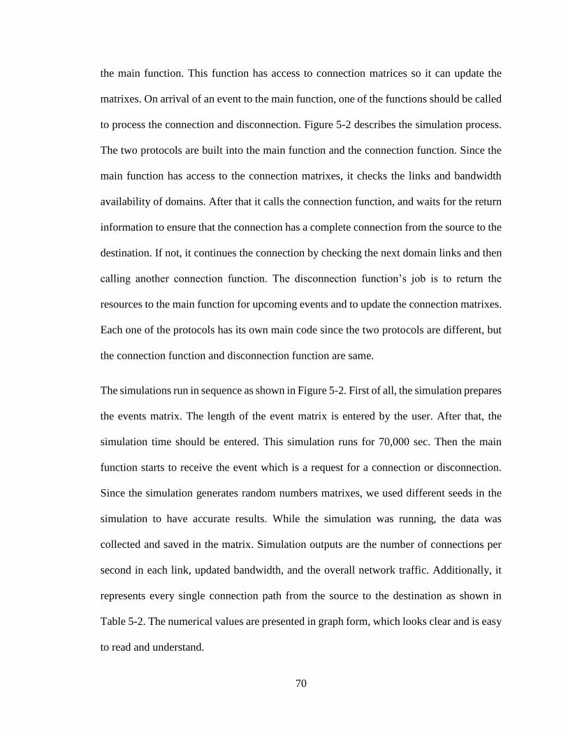
70
the main function. This function has access to connection matrices so it can update the
matrixes. On arrival of an event to the main function, one of the functions should be called
to process the connection and disconnection. Figure 5-2 describes the simulation process.
The two protocols are built into the main function and the connection function. Since the
main function has access to the connection matrixes, it checks the links and bandwidth
availability of domains. After that it calls the connection function, and waits for the return
information to ensure that the connection has a complete connection from the source to the
destination. If not, it continues the connection by checking the next domain links and then
calling another connection function. The disconnection function’s job is to return the
resources to the main function for upcoming events and to update the connection matrixes.
Each one of the protocols has its own main code since the two protocols are different, but
the connection function and disconnection function are same.
The simulations run in sequence as shown in Figure 5-2. First of all, the simulation prepares
the events matrix. The length of the event matrix is entered by the user. After that, the
simulation time should be entered. This simulation runs for 70,000 sec. Then the main
function starts to receive the event which is a request for a connection or disconnection.
Since the simulation generates random numbers matrixes, we used different seeds in the
simulation to have accurate results. While the simulation was running, the data was
collected and saved in the matrix. Simulation outputs are the number of connections per
second in each link, updated bandwidth, and the overall network traffic. Additionally, it
represents every single connection path from the source to the destination as shown in
Table 5-2. The numerical values are presented in graph form, which looks clear and is easy
to read and understand.

71
Generate domain Matrix
Each Matrix content information of each
Domain
Switch information Number of switch Next Domain Next Switch Link BW
Each Domain
Enter the number of
Events
Initialize matrix and variables
Start i=1 : Events Num.
loop to generate Events Matrix
Generate uniform random numbers for Domain and switch
Which are source and destination
Generate exponential random for
Interval events Duration events
End i== event number
NO
Enter the Time
Yes
Timert<= Event Time
t == con eventt == dic event
Connection method
Connection Call
IFCheck for direct
connection
Send request to next domains and
reserve connection
No
Test the available link
BWNO
Update the Router BW Table
YES
Reserve Connection
YES
Send approval to connection requester
Fail connection
Figure 5-2 Simulation flow chart

72
Table 5-2 Simulation update output
Event ID Domain# Switch# Next Dom Next Switch ROUTE (Domain, Switch)
1 3 3 4 3 (3,3) ---> (3,1) >>>>> (4,3) ---> (4,3)
1 4 3 1 3 (4,3) ---> (4,2) >>>>> (1,2) ---> (1,3)
2 1 2 2 3 (1,2) ---> (1,3) >>>>> (2,5) ---> (2,3)
3 4 2 3 2 (4,2) ---> (4,1) >>>>> (3,2) ---> (3,2)
3 3 2 2 4 (3,2) ---> (3,3) >>>>> (2,3) ---> (2,4)
4 2 3 3 3 (2,2) ---> (2,3) >>>>> (3,3) ---> (3,3)
4 3 2 4 1 (3,3) ---> (3,2) >>>>> (4,1) ---> (4,1)
5 4 4 1 3 (4,2) ---> (4,2) >>>>> (1,2) ---> (1,3)
6 2 1 1 1 (2,4) ---> (2,5) >>>>> (1,3) ---> (1,1)
7 3 1 4 2 (3,1) ---> (3,1) >>>>> (4,3) ---> (4,2)
5.4 Results and discussion
These results represent the behavior of traffic in the simulation network. There are seven
figures, each one presenting a domain-to-domain connection and the eighth one presenting
the overall network traffic. In additional to that, the figures show two curves, which
represent the high bandwidth protocol and the less number of hops protocol, to compare
between them.

73
We will discuss each link separately, then we will compare between the two protocols and
at the end we will talk about the overall network traffic.
Starting with the links between Domain 1 and Domain 2, there are two connections
presented in Figures 5-3 and 5-4. Figure 5-3 shows the traffic that passed from Edge Switch
3 of Domain 1 (1-3) to Domain 2 Edge Switch 5 (2-5). The red curve presents the traffic
when the less number of hops routing protocol is used to calculate a path. It is a fluctuation
with time because the number of connections past this link ripples with time. The average
numbers of connections handled by these links are 25 connections per second which means
it is 25% of the total capacity of the link. This link can handle up to 100 connections of 10
GB each. Figure 5-4 presents the connection between Edge Switch 4 of Domain 1 (1-4)
and Edge Switch 1 of Domain 2 (2-1). The red curve is similar to that of Figure 5-3. The
main part of the curve is 25 connections and the standard deviation is 5. On the other hand,
the blue curves of both figures present the traffic when we use the high bandwidth link
routing protocol. The mean number of connections that pass by (1-3) to (2-5) is 32
connections per second. It is high compared to the number of connections that flow in the
link from (1-4) to (2-4). The main number of this connection is 12 connections per second.
The difference is 20 connections per second. This difference came from the variant size of
data that passes through this link. This means that traffic passing through (1-3) to (2-5) has
a small data size; therefore, the number of connections is high, but the traffic that is handed
over by Link (1-4) to (2-1) has a large data size so the number of connections is small. Part
of the traffic that pass through these goes to Domain 2 and the other part goes to Domain
3.

74
Figure 5-4 Domain 1 Edge Switch 4 to Domain 2 Edge Switch 1 link traffic performance.
Figure 5-3 Domain 1 Edge Switch 3 to Domain 2 Edge Switch 5 link traffic performance.

75
Traffic between Domain 2 to Domain 3 is higher than the traffic between Domain 1 and
Domain 2 since it contains the traffic of Domain 1 that passes through to Domain 3. Figure
5-5 presents the connection link between Domain 2 Edge Switch 4 (2-4) and Edge Switch
5 in Domain 3 (3-5). The mean of the red curve is 30 connections per second. It also
changes with time to reach up to 37 connections. Figure 5-6 shows the link connection
between Domain 2, Edge Switch 3 (2-3) and Domain 3 Edge Switch 3 (3-3). The red curve
in this figure shows a smaller number of connections which depends on the final destination
of the traffic. In contract, the blue curves in both Figures 5-5 and 5-6 are alike. The mean
is 33 in both curves. Since the traffic is distributed equally between the links, the two curves
look the same. Both protocols show close performance in Links (2-4) to (3-5) but in Link
(2-3) to (3-3) they do not. The number of connections when applying the high bandwidth
link protocol is higher than when applying the less number of connections protocol. This
difference is because of the number of events that arrive at the main code.
Figures 5-7 and 5-8 present traffic from Domain 3 to Domain 4. There are two links, first
one is from Edge Switch 1 of Domain 3 to Edge Switch 3 of Domain 4 (3-1) to (4-3) and
the second one is from Edge Switch 2 of Domain 3 to Edge Switch 1 of Domain 4 (3-2) to
(4-1). The red curve and blue curve in both figures show the same number of connections
per second. This is because the traffic that pass by is mainly from Domain 3 to Domain 4
and a small part of it from Domain 4 to Domain 3 and vice versa.

76
Figure 5-5 Domain 2 Edge Switch 3 to Domain 3 Edge Switch 3 link traffic performance.
Figure 5-6 Domain 2 Edge Switch 4 to Domain 3 Edge Switch 5 link traffic performance.
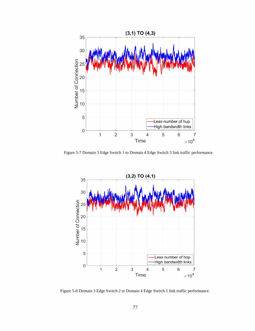
77
Figure 5-8 Domain 3 Edge Switch 2 to Domain 4 Edge Switch 1 link traffic performance.
Figure 5-7 Domain 3 Edge Switch 1 to Domain 4 Edge Switch 3 link traffic performance.

78
The last link in the network is the only on link between Domain 1 and Domain 4 (Figure
5-9). This link handles more traffic than any other links in the network. The reason for that
is because all traffic that is sent from Domain 1 to Domain 4 or in the opposite direction
passes by this link. It is noticed that the number of connections when applying the less
number of hops protocol is higher than when applying the high bandwidth link protocol,
since some of the traffic that is sent from Domain 1 to Domain 3 also passes by Domain 4.
It depends on the location of the flow of data to the final destination.
Figure 5-9 Domain 4 Edge Switch 2 to Domain 1 Edge Switch 2 link traffic performance.

79
Figure 5-10 Network traffic performance.
Figure 5-10 presents the overall network traffic performance. By looking at the two curves,
we can notice that the performance of the two protocols that are used to integrate IP into
the optical network by using SDN are quite similar. This gives us the flexibility to use
either one of them. It is also clear from Figure 5-10 that the performance of the network is
stable.
5.5 Conclusion
Results were similar, as we expected, which improves the performance of the network
traffic. Additionally, it helps to understand the traffic that flowed in the network and
simulated the SDN controller. Also, the output table is good enough to track the flow of

80
data from domain to domain and the results became clear to a network administrator. The
result presentation is identical to the presentation of the SDN application layer as
mentioned in Chapter 3.
81
6 Conclusion and Future work
6.1 Future work
There is a lot to be done in SDN; the simulation is the first step to test the idea of integrating
IP into an optical network by using SDN. Basically what has been done is the main SDN
controller simulation, and a study of the network performance. Implementing this concept
by using a physical SDN controller and network equipment will get into a deep
understanding of how this system is important and what are the advantages and
disadvantages of it.
A MATLAB simulator has been used to verify our idea with a pre-set events table and it
may only show one side of the simulation. By using a different network simulator with
contentious simulation time, we can run the network for contentious time and have more
data which leads to more analysis.
6.2 Conclusion
The current network architecture needs to be modified to handle growth that happens in
the network. It is very important for this transaction to be smooth while not affect the
performance of the network. So integrating IP protocol into an optical network helps to
improve the performance of the network by controlling traffic intelligently which can help
to reduce the bandwidth cost and to use network resources wisely. This idea is ideal for
sending a flow of data rather than sending packets, since the new technology of cloud
computing requires sending and receiving data continuously.

82
SDN has entered the network recently and achieves a very good result in improving the
network operation. Also, integrating SDN in a MAN or WAN does a good job along with
integrating IP into optical networks by using an intelligent and centralized controller. In
addition to that, the three main concepts of SDN, forwarding, control, and management,
make the network easy to expand and easy to manage and control. SDN also helps the
network administrators to configure the network easily and rapidly.
Integrating IP into an optical network by SDN provides an intelligence to the network
controller and traffic management. The simulation presents a positive result as a first step
to test this new idea. Also, it shows how the traffic moves smoothly from domain to
domain. One more point is that monitoring network performance and following traffic
became easy and practical, because each network node has up-to-dated information about
its surrounding routers.
This work has clarified the idea of integrating IP protocol into an optical network by using
SDN and the results of the simulation present the output of this integration.

83
7 Bibliography
[1] N. Zhang, "Research on Novel Architecture of Optical Network," in International
Conference on Networking and Digital Society, IEEE., 2010.
[2] W. Yang and T. Hall, "An infrastructure with a unified control plane to integrate IP
into optical metro networks to provide flexible and intelligent bandwidth on demand
for cloud computing," in SPIE Proceedings , 2013.
[3] A. Tanenbaum and D. Wetherall, Comupter Network, Boston: PEARSON, 2011.
[4] D. Serpanos and T. Wolf, The layered Internet architechture and network protocol,
Elsevier, 2011.
[5] C. System, Internetworking Technologies Handbook, Indianapolis: Cisco Press,
2004.
[6] F. Halsall, Computer Netwoking and the Internet, United States of America: Pearson
Education Limited, 2005.
[7] P. Datacom, "Ethernet Switch Service - MAN," Pinnacle Datacom, [Online].
Available: http://pinnacledatacom.com/ethernet-switched-service-man.php.
[Accessed 23 03 2015].

84
[8] N. Olifer and V. Olifer, Computer Network Principles, Technologies and Protocoles
for Network Design, USA: A-List Publishing, 2006.
[9] L. Peterson and B. Davie, Computer Networks a System Approach, San Francisco:
Elsevier, 2007.
[10] A. ADETUNJI, "Network Layer," [Online]. Available:
http://homepages.uel.ac.uk/u0415051/OSI%20MODEL/network.htm. [Accessed 11
03 2015].
[11] M. Soliman, B. Nandy, I. Lambadaris and P. Ashwood-Smith, "Exploring Source
Routed Forwarding in SDN based WANs," in IEEE ICC 2014 - Next-Generation
Networking Symposium, Sydney, 2014.
[12] T. Sridhar, "Layer 2 and Layer 3 Switch Evolution," The Internet Protocol, vol. 1,
no. 2, p. 38, 1998.
[13] Kioskea, "Network equipment - Bridges," [Online]. Available:
http://en.kioskea.net/contents/307-network-equipment-bridges. [Accessed 11 03
2015].
[14] S. Gringeri, N. Bitar and T. Xia, "Extending software defined network principles to
include optical transport," Communications Magazine, IEEE, vol. 51, no. 3, pp. 32-
40, 2013.
[15] S. Sezer, S. Scott-Hayward, P. Chouhan, B. Fraser, D. Lake, J. Finnegan, N. Viljoen,
M. Miller and N. Rao, "Are we ready for SDN? Implementation challenges for

85
software-defined networks," Communications Magazine, IEEE, vol. 51, no. 7, pp.
36-43, 2013.
[16] B. Nunes, M. Mendonca, X. Nguyen, K. Obraczka and T. Turletti, "A Survey of
Software- Defined Networking: Past, Present, and Future of Programmable
Networks," IEEE Communications Surveys And Tutorials, vol. 16, no. 3, pp. 1617-
1634, 2014.
[17] Network ONF Software-Defined, "The New Norm for networking," Open
Networking Foundation, [Online]. Available: https://www.opennetworking.org.
[Accessed 03 02 2015].
[18] S. Myung-Ki, N. Ki-Hyuk and K. Hyoung-Jun, "Software-defined networking
(SDN): A reference architecture and open APIs," in ICT Convergence (ICTC), 2012
International Conference, 2012.
[19] S. Paul, Software Defined Application Delivery Networking, Saint Louis, Missouri:
Washington University in St. Louis, 2014.
[20] D. Kreutz, F. Ramos, P. Esteves Verissimo, C. Esteve Rothenberg, S. Azodolmolky
and S. Uhlig, "Software-Defined Networking: A Comprehensive Survey,"
Proceedings of the IEEE, vol. 103, no. 1, pp. 14-76, 2015.
[21] S. Jain, A. Kumar, S. Mandal, J. Ong, L. Poutievski, A. Singh, S. Venkata, J.
Wanderer, J. Zhou and M. Zhu, "B4: Experience with a Globally-Deployed Software
Defined WAN," in SIGCOMM’13, Hong Kong, China, 2013.

86
[22] S. H. Yeganed and Y. Ganjali, "Kandoo: a framework for efficient and scalable
offloading of control applications," in ACM SIGCOMM, New York, 2012.
[23] M. Rouse, "TechTarget," May 2013. [Online]. Available:
http://searchsdn.techtarget.com/definition/programmable-network-PN. [Accessed 5
February 2015].
[24] R. G. Little, "Making Networks Virtual: The Latest on SDN Technologies,"
SearchSDN.com e-publication, Newton, 2014.
[25] Foundation Open Networkig, "OpenFlow Switch Specification," Open Networkig
Foundation (ONF), 2013.
[26] L. Liu, T. Tsuritani, I. Morita, H. Guo and J. Wu, "OpenFlow-based Wavelength Path
Control in Transparent Optical Networks: a Proof-of-Concept Demonstration," in
ECOC Technical Digest, America, 2011.
[27] V. Gudla, S. Das, A. Shastri, G. Parulkar, N. McKeown and L. Kazovsky,
"Experimental Demonstration of OpenFlow Control of Packet and Circuit Switches,"
in Optical Fiber Communication (OFC), collocated National Fiber Optic Engineers
Conference, 2010 Conference on (OFC/NFOEC), 2010.
[28] M. Rouse, "Network Vertualization," Septemner 2006. [Online]. Available:
http://searchservervirtualization.techtarget.com/definition/network-virtualization.
[Accessed 16 February 2015].

87
[29] "sdxCentral," SDX Central, [Online]. Available:
https://www.sdxcentral.com/resources/network-virtualization/whats-network-
virtualization/. [Accessed 17 February 2015].
[30] S. Garrison, "Understanding the differences between Software Defined Network,
Network virtualization and Network Functions Virtualization," NETWORKWORD,
11 February 2014. [Online]. Available:
http://www.networkworld.com/article/2174268/tech-primers/understanding-the-
differences-between-software-defined-networking-network-virtualizati.html.
[Accessed 17 February 2015].
[31] P. Göransson and C. Black, Software Defined Networks A Comprehensive
Approach, NEW YORK: ELSEVIER, 2014.
[32] S. Shenker, "The future of network and the past of protocols," in Open Networking
Summit, Palo, Alto, CA, USA: Stanford University, 2011.
[33] F. O. Netwroking, "Optical transport working group OTWG," 2013.
[34] M. Morisy, "TechTarget," [Online]. Available:
http://searchsdn.techtarget.com/feature/Software-defined-networking-applications-
move-beyond-the-data-center. [Accessed 02 April 2015].
[35] S. H. Yeganeh, A. Tootoonchian and Y. Ganjali, "On Scalability of Software-Defined
Networking," IEEE Communications Magazine, vol. 51, no. 2, pp. 136-141, 2013.

88
[36] R. Ahmed and R. Boutaba, "Design Considerations for Managing Wide Area
Software Defined Networks," IEEE Communications Magazine, vol. 52, no. 7, pp.
116-123, 2014.
[37] A. Tavakoli, M. Casado, T. Koponen and S. Shenker, "Applying NOX to the
Datacenter," in Hot Topics in Networks Workshop, 2009.
[38] H. Kim, J. Santos, Y. Turner, M. Schlansker, J. Tourrilhes and N. Feamster,
"CORONET: Fault tolerance for Software Defined Networks," in IEEE International
Conference, 2012.
[39] A. Tootoonchian and Y. Ganjali, "HyperFlow: A distributed control plane for
OpenFlow," in internet network management conference on Research on enterprise
networking, 2010.
[40] A. Saleh and S. M. Jane, "All-Optical NNetworking Evalution, Benefits, Chalenges,
and Future Vision," in IEEE, 2012.
[41] A. Jukan and J. Mambretti, "Evolution of Optical Networking Toward Rich Digital
Media Services," Proceedings of the IEEE , vol. 100, no. 4, pp. 855- 871, 2012.
[42] S. Gringeri, N. Bitar and a. T. J. Xia, "Extending Software Defined Network
Principles to Include Optical Transport," IEEE Communications Magazine, vol. 51,
no. 3, pp. 33-41, 2013.

89
[43] W. Stallings, "Software-Defined Networks and OpenFlow," The Internet Protocol
Journal, Volume 16, No. 1, vol. 16, no. 1, 2013.