Integrating-averaging Sound Level Meter Type 2240web.arch.usyd.edu.au/~stewa_k/Type 2240.pdf ·...
44
BE 1695 – 11 October 2003 Integrating-averaging Sound Level Meter Type 2240 User Guide Sonomètre intégrateur Type 2240 – Guide de l’utilisateur Integrierende Schallpegelmesser Typ 2240 – Bedienungshandbuch Fonometro integratore-mediatore 2240 – Manuale utente Sonómetro integrador-promediador 2240 – Manual de usuario
Transcript of Integrating-averaging Sound Level Meter Type 2240web.arch.usyd.edu.au/~stewa_k/Type 2240.pdf ·...

BE 1695 – 11 October 2003
Integrating-averagingSound Level Meter
Type 2240
User Guide
Sonomètre intégrateur Type 2240 – Guide de l’utilisateur
Integrierende Schallpegelmesser Typ 2240 – Bedienungshandbuch
Fonometro integratore-mediatore 2240 – Manuale utente
Sonómetro integrador-promediador 2240 – Manual de usuario
BE169511.book Page i Tuesday, October 28, 2003 10:26 AM

Copyright 2003, Brüel & Kjær Sound & Vibration Measurement A/S
All rights reserved. No part of this publication may be reproduced or distributed in anyform, or by any means, without prior written consent from Brüel & Kjær Sound & VibrationMeasurement A/S, Nærum, Denmark
BE169511.book Page v Tuesday, October 28, 2003 10:26 AM

Contents
Part 1English .............................................................................................................................. 1
Chapter 1: Introduction ........................................................................................................ 3Chapter 2: Getting Started ................................................................................................... 7Chapter 3: Making a Measurement.................................................................................... 15Chapter 4: Basic Operation................................................................................................ 17Chapter 5: Practical Guidelines ......................................................................................... 25Chapter 6: Maintenance and Service................................................................................. 29Chapter 7: Specifications ................................................................................................... 31Chapter 8: Glossary ........................................................................................................... 35
Part 2Français .......................................................................................................................... 41
Chapitre 1: Généralités ...................................................................................................... 43Chapitre 2: Se familiariser avec l’appareil.......................................................................... 47Chapitre 3: Mesurer ........................................................................................................... 57Chapitre 4: Fonctions principales....................................................................................... 59Chapitre 5: Conseils de manipulation ................................................................................ 69Chapitre 6: Entretien et réparation..................................................................................... 73Chapitre 7: Spécifications .................................................................................................. 75Chapitre 8: Glossaire ......................................................................................................... 79
Teil 3Deutsch........................................................................................................................... 85
Kapitel 1: Einführung.......................................................................................................... 87Kapitel 2: Erste Schritte ..................................................................................................... 91Kapitel 3: Durchführung von Messungen......................................................................... 101Kapitel 4: Wichtige Bedienfunktionen .............................................................................. 103Kapitel 5: Praktische Hinweise......................................................................................... 113Kapitel 6: Wartung und Service ....................................................................................... 117Kapitel 7: Technische Daten ............................................................................................ 119Kapitel 8: Glossar............................................................................................................. 123
Parte 4Italiano .......................................................................................................................... 129
Capitolo 1: Introduzione ................................................................................................... 131Capitolo 2: Preparazione ................................................................................................. 135Capitolo 3: Esecuzione di una misura.............................................................................. 145Capitolo 4: Funzionamento di base ................................................................................. 147Capitolo 5: Linee guida .................................................................................................... 155Capitolo 6: Assistenza e manutenzione........................................................................... 159Capitolo 7: Dati tecnici ..................................................................................................... 161Capitolo 8: Glossario........................................................................................................ 165
BE169511.book Page 3 Tuesday, October 28, 2003 10:26 AM

Part 5Español ......................................................................................................................... 171
Capítulo 1: Introducción ................................................................................................... 173Capítulo 2: Puesta en marcha ......................................................................................... 177Capítulo 3: Cómo hacer una medida ............................................................................... 187Capítulo 4: Operaciones Básicas..................................................................................... 189Capítulo 5: Practical Guidelines....................................................................................... 199Capítulo 6: Mantenimiento y Servicio .............................................................................. 203Capítulo 7: Especificaciones............................................................................................ 205Capítulo 8: Glosario ......................................................................................................... 209
BE169511.book Page 4 Tuesday, October 28, 2003 10:26 AM

1
Part 1English
BE169511.book Page 1 Tuesday, October 28, 2003 10:26 AM

2
BE169511.book Page 2 Tuesday, October 28, 2003 10:26 AM

3
Chapter 1Introduction
Welcome ................................................................................................................................... 4Summary of Contents................................................................................................................ 4
Conventions Used in this Guide ...................................................................................... 4About Type 2240 ....................................................................................................................... 5
Uses and Features .......................................................................................................... 5
BE169511.book Page 3 Tuesday, October 28, 2003 10:26 AM

Integrating-averaging Sound Level Meter Type 2240 – User Guide4
Welcome
This user guide introduces you to Type 2240 Integrating-averaging Sound Level Meter, how theinstrument works, which parameters you can measure, and how the instrument should be oper-ated. In addition, some practical hints and guidelines are provided for, including all relevanttechnical specifications. Finally, a glossary is added to help with specific terminology found inthis guide.
Summary of Contents
• Chapter 1 – Introduction: provides a general overview of the user guide and describes Sound Level Meter Type 2240’s uses and features
• Chapter 2 – Getting Started: provides basic introductory information to sound level meters and your instrument, including: general terminology, description of instrument parts, display and key definitions, and battery installation
• Chapter 3 – Making a Measurement: step-by-step instructions on how to take a measure-ment with Type 2240
• Chapter 4 – Basic Operation: contains information and appropriate procedures on how to use Type 2240, including calibration, start-up, reading and key operation guides
• Chapter 5 – Practical Guidelines: gives tips on how to take a successful sound level meas-urement, and what conditions and actions to avoid
• Chapter 6 – Maintenance and Service: provides care, cleaning and storage instructions as well as information on where to go for service of your instrument
• Chapter 7 – Specifications: a comprehensive listing of technical specifications of Type 2240
• Chapter 8 – Glossary: a quick list of terms used in this guide and their definitions
Conventions Used in this Guide
Instructions and descriptions that refer to Type 2240 instrument keys are shown with the keyicons as seen on the instrument. See Chapter 2 for a complete list of of key icons and theirfunctions.
Instructions and descriptions that refer to Type 2240 instrument display text are indicated usingCourier type face. For example, “Press until LAeq is visible on the screen”.
Terms that are defined in the Glossary (Chapter 8), are highlighted in italic bold.
BE169511.book Page 4 Tuesday, October 28, 2003 10:26 AM

PART 1English 5
About Type 2240
Uses and Features
Type 2240 is a Class 1 integrating-averaging sound level meter that measures time-averagesound level as defined in the IEC 61672-1 standard. Its uses and features include:
• Simple sound level checks
• Control of noise levels in the workplace
• Complaint investigation
• Quick and easy to use
• Conforms with IEC 61672-1 Class 1, IEC 60651 and 60804 Type 1, ANSI S 1.4–1983 Type S1 and ANSI S 1.43–1997 Type 1
• Simultaneous RMS and Peak measurements (with independent frequency weightings)
• Measures LAF, LAeq, LAFmax and LCpeak
• No parameter configuration needed, the instrument is ready to measure from the start
• Large LCD display screen for easy reading
• Quasi-analogue bar graph shows current sound pressure level
• Under-range and overload indicators
BE169511.book Page 5 Tuesday, October 28, 2003 10:26 AM

Integrating-averaging Sound Level Meter Type 2240 – User Guide6
BE169511.book Page 6 Tuesday, October 28, 2003 10:26 AM
7
Chapter 2Getting Started
What is a Sound Level Meter? .................................................................................................. 8Description of Type 2240 Sound Level Meter ........................................................................... 8
Sound Level Parameters ................................................................................................. 8Instrument Components ................................................................................................ 10
Installing Batteries ................................................................................................................... 13
BE169511.book Page 7 Tuesday, October 28, 2003 10:26 AM

Integrating-averaging Sound Level Meter Type 2240 – User Guide8
Type 2240 is a high performance, Class 1, integrating-averaging sound level meter with aneasy-to-use interface for quick and simple measurements. This chapter details the instrument’scomponents and basic sound level parameters involved in measuring. With this information youshould be able to immediately start using your sound level meter. However, it is recommendedthat you read the entire guide before using your Type 2240 in order to achieve the best resultsfrom your instrument.
What is a Sound Level Meter?
A sound level meter is an instrument that is designed to measure sound levels in a standardisedway. A sound level meter comprises a microphone, a main processor and a read-out unit. Themicrophone converts sound to an equivalent electric signal, which is processed by the instru-ment. Processing includes applying frequency and time weightings to the signal as specified byinternational standards, such as IEC 61672-1 to which Type 2240 conforms.
Frequency weighting adjusts how the sound level meter responds to different sound frequen-cies. This is necessary because the human ear's sensitivity to sound varies according to thesound’s frequency. The most common frequency weighting in use is A-weighting, which adjustsa signal in a way that best resembles the human ear's response at medium-range levels. It is theweighting required for nearly all environmental and workplace noise measurements, and isspecified in international and national standards and guidelines. All of Type 2240’s measure-ment parameters apply A-weighting, except for the measurement of peak levels where the ‘C’frequency weighting is applied. In this case, C-weighting is used to take into account the energypresent at low frequencies even if they are not particularly annoying.
Time weighting specifies how the sound level meter reacts to changes in sound pressure. It isan exponential averaging of the fluctuating signal, providing an easy-to-read value. Type 2240always applies the Fast, or ‘F’ time weighting, which is the required weighting according to thevast majority of international and national standards and guidelines.
Once the signal is processed through the weighting filters, the resulting sound pressure level isdisplayed in decibels (dB) on the instrument's display. In Type 2240, the sound pressure levelvalues are updated once per second.
Description of Type 2240 Sound Level Meter
Sound Level Parameters
There are four sound level parameters measured by Type 2240: LAF, LAeq, LAFmax and LCpeak.Once a measurement is started (using control key), all four parameters are measured simul-taneously, you just need to choose which one you want to be displayed using the parametercontrol key . Press this key at any time during, or after, a particular measurement to switchto another sound level reading.
BE169511.book Page 8 Tuesday, October 28, 2003 10:26 AM

PART 1English 9
The four sound level parameters are:
• LAF: The ‘A’ frequency-weighted and ‘F’ time-weighted sound pressure level. This parameter is always displayed when the instrument is switched on, even if you have not started a meas-urement. It is an instantaneous value, which is mainly used to determine the approximate sound levels in order to select the appropriate sound level range to measure.
Fig.2.1LAF parameter displayed
• LAeq: The equivalent continuous, ‘A’ frequency-weighted sound pressure level. LAeq is a lin-ear average of all the varying sound pressure levels detected during a measurement. For a number of international and national standards, it is the key parameter in determining annoy-ance from environmental noise and assessing the risk of hearing deficiencies induced by expo-sure to high sound levels at the work place. Note: LAeq is not time-weighted.
Fig.2.2LAeq parameter displayed
• LAFmax: The maximum ‘A’ frequency-weighted and ‘F’ time-weighted sound pressure level detected during a measurement. It is the maximum value of LAF detected during a measure-ment. It is often used in comparison with another parameter (for example: LAeq) to ensure a
single noise event does not exceed a limit.
Fig.2.3LAFmax parameter displayed
• LCpeak: The maximum ‘C’ frequency-weighted, peak sound pressure level detected during a
measurement. LCpeak is used to assess risks of hearing deficiencies induced by very high sound pressures of short durations at work places. Remember that peak levels can be very high
BE169511.book Page 9 Tuesday, October 28, 2003 10:26 AM

Integrating-averaging Sound Level Meter Type 2240 – User Guide10
without being harmful or even annoying, so care should be taken to use LCpeak only for its intended purpose. Such high values can be misleading in situations where they are not called for. Note: LCpeak is not time-weighted.
Fig.2.4LCpeak parameter displayed
LAFmax, LCpeak, and LAeq sound level parameters begin calculation only when a measurement isstarted (press ), and stop only when the measurement is stopped (press again). LAF iscalculated automatically when the sound level meter is switched on.
The measured values of LAFmax, LCpeak, and LAeq are cleared whenever a new measurement isstarted.
Instrument Components
Fig.2.5 Front, side and back view of Type 2240 instrument
The following descriptions refer to the numbered instrument parts in Fig.2.5:
1) Sound Level Meter body: The main part of your instrument.
2
3
4
5
6 7
8
9
11
1
10
Front Panel Side Panel Back Panel
BE169511.book Page 10 Tuesday, October 28, 2003 10:26 AM

PART 1English 11
2) Sliding cover: Underneath the cover is a quick reference guide to help you use the threecontrol keys for setup and display of measurements. Slide to open, do not press. A diagramof the quick guide is found in Fig.2.6.
3) Microphone: Brüel & Kjær’s Prepolarized Free-field ½″ Microphone Type 4188 is used. Arobust and reliable microphone with a wide frequency range.
4) Preamplifier: Conditions the microphone signal before further processing.
5) Display screen: An LCD display showing:
a) the sound level parameter currently being viewed
b) elapsed measurement time
c) measurement reading in dB (decibels)
d) quasi-analogue bar graph representing current sound pressure level
e) battery level indicator
6) Start/Stop key : Press to start or stop a measurement.
7) Sound Level Parameter key : Press to scroll through sound level parameters that areavailable to display (LA, LAeq, LAmax, or LCpeak), or hold down for 3 seconds to calibrate.
8) Sound Level Range key : Press to set sound level range (30 – 110 dB or 60 – 140 dB).
9) Calibration switch: Adjust instrument calibration using the included screwdriver.
10) Power switch: Turn the instrument on and off.
11) Battery compartment: Slide the compartment’s lid to replace batteries when needed.Instructions on replacing batteries follow in “Installing Batteries” on page 13.
Control Keys
Fig.2.6Under the front panel’s sliding cover is a quick guide to help you use the three control keys LA
LAeq
LAmax
LCpeak
(3 sec.=Cal.)
30-110dB
60-140dB
BE169511.book Page 11 Tuesday, October 28, 2003 10:26 AM

Integrating-averaging Sound Level Meter Type 2240 – User Guide12
Note: All keys function step-wise, as illustrated by the quick guide’s use of arrows. Press a keyto step through the available functions. When the last possible function comes up, the instru-ment will automatically scroll through the choices again as you continue to press.
Start/Stop Key
This key controls the initiation and completion of a measurement.
Sound Level Parameter Key
This key controls which sound level parameter is displayed. It is not necessary to configure anysound level parameter, as all four parameters are measured simultaneously as soon as a meas-urement is started.
Quick Guide Symbol Instructions
To start a measurement, press until appears on the display
To stop a measurement, press until stops flashing on the display
Quick Guide Symbol Instructions
LA
To display the A-weighted sound pressure level, press
until LA appears on the display. Note: LA is time- weighted, using Fast weighting
LAeq
To display the A-weighted, equivalent continuous sound pressure level, press
until LAeq appears on the display
LAmax
To display the maximum A-weighted sound pressure level, press until LAmax appears on the display. Note: LAmax is time weighted, using Fast weighting
LCpeak
To display the C-weighted, peak sound pressure level, press until LCpeak appears on the display.
BE169511.book Page 12 Tuesday, October 28, 2003 10:26 AM

PART 1English 13
The Sound Level Parameter key can also be used to electrically calibrate the instrument byholding down for three seconds. Actual adjustments are made using the calibration switchon the side panel, and the included screwdriver. It is a good idea to calibrate the instrumentbefore and after a series of measurements to conform to required standards and ensure preciseresults each time. See “Calibration” on page 18. for more information.
Sound Level Range Key
This key controls the sound level range to be measured.
Installing Batteries
Type 2240’s power supply consists of two AA-size (IEC R 6 or LR 6) alkaline batteries. Toinstall the batteries, do the following:
1) Make sure the sound level meter is switched off.
2) The battery compartment is located in the centre of the instrument’s back panel. Slide thecover off.
Fig.2.7Type 2240 with the battery cover removed
3) Insert 2 new batteries following the +/– orientation shown at the bottom of the batterycompartment.
Quick Guide Symbol Instructions
30 – 110 dB
To measure in this range, press until the bar graph shows a range of 30 – 110 dB
60 – 140 dB
To measure in this range, press until the bar graph shows a range of 60 – 140 dB
BE169511.book Page 13 Tuesday, October 28, 2003 10:26 AM

Integrating-averaging Sound Level Meter Type 2240 – User Guide14
4) Slide the compartment cover back into place.
5) Switch the Power on. The battery symbol in the bottom left-hand corner of the instrumentdisplay should indicate a full battery level . Note: If the instrument does not turn on,check that you have inserted the batteries correctly.
The battery level has two black columns, each representing about 8 hours of remaining batterytime for a total of approximately 16 continuous hours of use (at room temperature). In extreme-ly cold or hot environments, the remaining time may be less.
Both columns will be shown in the indicator when the battery level is full. It is time to replacethe batteries when the indicator is empty and flashing.
Caution:
It is possible for batteries to explode or leak if they are handled incorrectly, so:
• For long-term storage, remove the batteries and keep the sound level meter in a dry place
• Never mix different makes or types of battery
• Never mix charged and discharged batteries
BE169511.book Page 14 Tuesday, October 28, 2003 10:26 AM

15
Chapter 3Making a Measurement
Measurement Procedure......................................................................................................... 16
BE169511.book Page 15 Tuesday, October 28, 2003 10:26 AM

Integrating-averaging Sound Level Meter Type 2240 – User Guide16
There is no pre-configuration necessary before making a measurement with Type 2240. Theinstrument is ready as soon as you turn it on. It is suggested, however, that you calibrate yourinstrument before a measurement to ensure correct measurement and display values, as well ascomplying to specific measurement standards. Your sound level meter is delivered factory cali-brated, so you can begin your first measurement immediately. Instructions for calibrating at alater time can be found in Chapter 4, “Basic Operation” on page 17.
Measurement Procedure
Setup and measurement are quick and simple:
1) Switch the sound level meter on using the Power switch on the side panel.
An LA value is displayed and the quasi-analogue bar begins reacting, both of which reflectthe instantaneous sound pressure level.
2) Select the sound level range, judging from the observed level (LAF and quasi-analoguebar).
3) Press the start button.
4) Be aware of possible under-range and overload indications. It may be neces-sary to change the sound level range to avoid these readings. See “Selecting the SoundLevel Range” on page 23.
5) Scroll through sound level parameters until the required parameter is displayed.
Fig.3.1 Examples of measurement options
6) Stop the measurement as necessary. For example, when LAeq is stable or the requiredtime has elapsed.
7) Toggle between parameters for comparison, if needed.
8) Write down the displayed result(s).
9) Press the start button to take a new measurement.
BE169511.book Page 16 Tuesday, October 28, 2003 10:26 AM

17
Chapter 4Basic Operation
Calibration ............................................................................................................................... 18Acoustical Calibration .................................................................................................... 18Electrical Calibration...................................................................................................... 20
Operation................................................................................................................................. 21Display........................................................................................................................... 21Measurement Start and Stop......................................................................................... 22Selecting the Sound Level Parameter .......................................................................... 23Selecting the Sound Level Range ................................................................................ 23Measuring LAeq.............................................................................................................. 23Making a Measurement of a Specified Duration............................................................ 24
Side Panel Functions .............................................................................................................. 24
BE169511.book Page 17 Tuesday, October 28, 2003 10:26 AM

Integrating-averaging Sound Level Meter Type 2240 – User Guide18
Calibration
Calibration is an adjustment of your sound level meter to ensure correct measurement anddisplay values. This is necessary because the sensitivity of the microphone and the response ofthe electronic circuitry can vary slightly over time or be affected by environmental conditionssuch as temperature and humidity. Often, calibration is required by national and internationalmeasurement standards. While you are not likely ever to experience a large drift or change insensititvity with Type 2240, it is nevertheless good practice to perform regular calibrations,normally before each set of measurements.
Your instrument supports two types of calibration:
• acoustical calibration that calibrates all the instrument's components (microphone, preampli-fier and electrical circuitry), wherein an acoustic signal of known magnitude and frequency is applied
• electrical calibration that does not include calibration of the microphone and preamplifier
Acoustical Calibration
Acoustical calibration is the preferred calibration method, particulary when standards and regu-lations require that a calibration is performed before a measurement.
To perform an acoustical calibration, use Brüel & Kjær Sound Level Calibrator Type 4231. Itprovides a stable sound pressure at 1 kHz and has minimal susceptibility to environmentalfactors. You use the calibrator's reference signal at 1 kHz to compare and adjust your soundlevel meter in full, including microphone, preamplifier and electronic circuitry.
The procedure for performing an acoustical calibration is simple:
1) Stand away from loud sound sources that may interfere with the calibrator's signal.
2) Fit Sound Level Calibrator Type 4231 carefully onto the sound level meter and rest theassembly on a table or other flat surface as shown in Fig.4.1.
Fig.4.1Sound Level Calibrator Type 4231 fitted onto your sound level meter
Ensure that the calibrator fits snugly on the microphone.
Type 2240
030224
BE169511.book Page 18 Tuesday, October 28, 2003 10:26 AM

PART 1English 19
3) Switch on the sound level meter. The LAF parameter is displayed (LA, Fast). If the meteris already switched on and another parameter displayed, press until LA is displayed.
4) Press to select the 30 – 110 dB sound level range (if not already displayed). This is thesound level meter’s reference range and should be used for calibration.
5) Switch on the calibrator. Type 4231 automatically emits a 1 kHz signal at 94 dB. Waitapproximately 5 seconds for all levels to stabilise.
6) Using the supplied screwdriver on the calibration switch located on Type 2240’s side panel,adjust your sound level meter to display 93.9 dB1.
Fig.4.2Adjusting calibration using the screwdriver on the calibration switch located on Type 2240’s side panel
1The reading should be 93.9 dB (not 94 dB) to agree with your sound level meter's microphone (Type 4188 free-field microphone). The 94 dB level specified for the calibrator is the pressure field in the coupler when the calibrator is fitted to the sound level meter. A slight correction must, therefore, be applied. This is explained in the calibrator's manual and the calibration chart supplied with your microphone.
BE169511.book Page 19 Tuesday, October 28, 2003 10:26 AM
Integrating-averaging Sound Level Meter Type 2240 – User Guide20
Note: Type 4231 can also provide a 114 dB signal (see Type 4231 User Manual BB 0910).Normally, this signal should not be used; however, if a calibration must be performed in avery noisy environment, you can use this level for calibration. In such a case you mustselect the 60 – 140 dB range and adjust the reading to 113.9 dB.
7) Remove the calibrator. It switches off automatically after a few seconds.
Electrical Calibration
An electrical calibration calibrates your sound level meter’s electronics only (not the micro-phone and preamplifier) and is based on a built-in reference signal.
The procedure is as follows:
1) Switch on the sound level meter.
2) Press for 3 seconds until you see the following display:
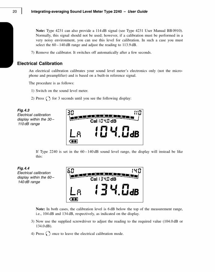
Fig.4.3Electrical calibration display within the 30 –110 dB range
If Type 2240 is set in the 60 – 140 dB sound level range, the display will instead be likethis:
Fig.4.4Electrical calibration display within the 60 –140 dB range
Note: In both cases, the calibration level is 6 dB below the top of the measurement range,i.e., 104 dB and 134 dB, respectively, as indicated on the display.
3) Now use the supplied screwdriver to adjust the reading to the required value (104.0 dB or134.0 dB).
4) Press once to leave the electrical calibration mode.
BE169511.book Page 20 Tuesday, October 28, 2003 10:26 AM
PART 1English 21
Operation
Display
During normal operation, you use the display screen to view your measurements. The informa-tion provided is described below.
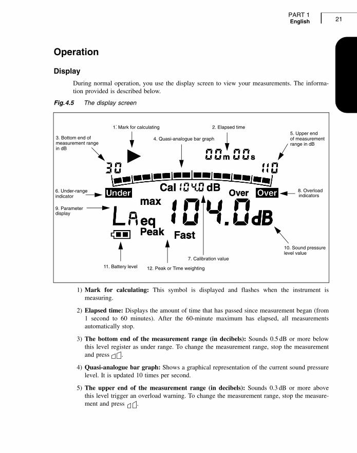
Fig.4.5 The display screen
1) Mark for calculating: This symbol is displayed and flashes when the instrument ismeasuring.
2) Elapsed time: Displays the amount of time that has passed since measurement began (from1 second to 60 minutes). After the 60-minute maximum has elapsed, all measurementsautomatically stop.
3) The bottom end of the measurement range (in decibels): Sounds 0.5 dB or more belowthis level register as under range. To change the measurement range, stop the measurementand press .
4) Quasi-analogue bar graph: Shows a graphical representation of the current sound pressurelevel. It is updated 10 times per second.
5) The upper end of the measurement range (in decibels): Sounds 0.3 dB or more abovethis level trigger an overload warning. To change the measurement range, stop the measure-ment and press .
1. Mark for calculating.
2. Elapsed time
4. Quasi-analogue bar graph5. Upper endof measurementrange in dB
6. Under-rangeindicator
7. Calibration value
8. Overloadindicators
9. Parameterdisplay
10. Sound pressurelevel value
11. Battery level 12. Peak or Time weighting
3. Bottom end ofmeasurement rangein dB
BE169511.book Page 21 Tuesday, October 28, 2003 10:26 AM

Integrating-averaging Sound Level Meter Type 2240 – User Guide22
6) Under-range indicator: Any sound detected during the measurement that is 0.5 dB ormore under the bottom end of the measurement range prompts the indicator. You may wantto change the measurement range to the lower level (30 – 110 dB), if applicable, by pressing
, otherwise your measurement results will reflect under range conditions.
7) Calibration value: When you press for 3 seconds, you start an electrical calibration ofthe instrument. The calibration value is based on the sound level range Type 2240 is pres-ently set up to measure (30 – 110 dB or 60 – 140 dB). Use the included screwdriver to adjustyour instrument to match this value.
8) Overload indicator: Sounds detected are 0.3 dB or more over the upper end of the meas-urement range. If an overload has occurred in the last second, is displayed with ablack background. If an overload has occurred at any time during a measurement inprogress, then the word Over has a plain background – this is called a latched overload.Latched overloads are cleared with the start of a new measurement and are not applicablewith the LA parameter.
You many want to change the measurement range to the higher level (60 – 140 dB), ifapplicable, by pressing , otherwise your measurement results will reflect overload con-ditions.
9) Parameter display: Shows the type of sound level reading displayed (LA, LAeq, LAmax, orLCpeak)
10) Sound pressure level value: The sound pressure level applies to the current parameterbeing displayed. It is updated once per second.
11) Battery level: When the batteries are new, this indicator displays two black level columns.As the batteries are used, the level falls. Replace the batteries when this indicator is emptyand flashing.
12) Peak or Time weighting: Peak is displayed together with the LC parameter to denote thatthe peak level for this parameter is displayed. Fast is displayed with LA and LAmax pa-rameters to denote that the 'F' time-weighting is used.
Measurement Start and Stop
When you switch on the instrument, the instantaneous sound pressure level is displayed (LA).Monitoring the LA for a short period gives you an idea which sound level range to choose.
While LAF is automatically measured, calculation of the other three parameters (LAeq, LAFmaxand LCpeak) must be initiated by pressing . Once a measurement is started, the arrow inthe upper left-hand corner of the display flashes to denote calculations are being made.Throughout the measurement time, you can view the various sound level parameters and theircurrent values by scrolling through the parameter menu . To stop a measurement, press .The flashing arrow in the display stops.
All results are cleared when the instrument is switched off.
BE169511.book Page 22 Tuesday, October 28, 2003 10:26 AM

PART 1English 23
Selecting the Sound Level Parameter
Selecting the right sound level parameter to display and report is dependent on the regulationsand standards to which you must comply.
Selecting the Sound Level Range
Sound Level Meter Type 2240 can measure sound pressure levels spanning from 30 dB to140 dB, separated in two ranges: 30 to 110 dB, and 60 to 140 dB. For any measurement task,you have to select one of the ranges by pressing .
The LAF parameter (LA) and the quasi-analogue bar are useful tools to help you decide whichrange to choose. Switch between the two ranges as you read the bar graph. Ideally your signalshould fluctuate around the middle graph without indications of under-range or overload
. If there are very large fluctuations in the sound pressure, for example, because impul-sive sounds are present, you may find it difficult to completely avoid at least one of theseindicators. If you have to choose between seeing under-range or overload conditions, select thehigher measurement range in order to avoid the overloads.1 This type of situation indicates thatthe signal fluctuates heavily, so be sure to use a sufficiently long averaging time to obtain astable level of LAeq.
Measuring LAeq
LAeq is always calculated for a specific duration, often due to standardised requirements, whichdemands a report of the measurement duration. LAeq durations are recorded as: LAeq,10min or inelongated form as “the 10 minute LAeq was xx.x dB”.
Type 2240 can calculate LAeq over durations ranging from 1 second to 60 minutes (in 1 secondsteps), with a built-in timer for accuracy. The current measurement time is displayed in theupper right-hand corner of the display. If regulations require measurements of a specific dura-tion, follow this regulation and pay attention to the instrument's timer. If no specific measure-ment time is required by regulation, you can determine the length of time on your own. Beloware some practical guidelines on how to make a proper LAeq measurement:
• After a significant amount of time, even considerable fluctuations in sound pressure will aver-
age out and LAeq will stabilise around a value. If you start a measurement and press until LAeq is displayed, you can easily observe this effect. Continue measuring until the value of
LAeq becomes stable.
• All measurement subjects exhibit some fluctuation. Depending on the fluctuation, you should select a measurement time that can limit the short variations of LAeq to one or a few tenths of a dB. The time required for this to happen depends on the amount of fluctuation. Remember that the LAeq averaging (measurement) time should always be reported.
1This is because you will then have values for LAmax and LCpeak that are not affected by an overload. With sufficient averaging time, the under-range conditions have only a negligible influence on the LAeq value.
BE169511.book Page 23 Tuesday, October 28, 2003 10:26 AM

Integrating-averaging Sound Level Meter Type 2240 – User Guide24
Making a Measurement of a Specified Duration
Regulations may require you to take a measurement of a specified duration (this duration maybe 1 second, 10 seconds, 5 minutes or some other value). In any case, it is normally required thatthe specified duration is strictly adhered to.
When making a measurement of specified duration, simply watch the timer at the upper right-hand corner of the display screen. For example, to make a 10-second measurement from astarting time of 00 m 00 s, simply press the stop button when the timer displays 00 m 10 s –at most 1 second after it displays that time. You can then scroll through the sound level parame-ters using the key to get a report of all the values for that 10-second period.
Side Panel Functions
Lifting the side panel flap, you find two functions: the power switch and calibration switch.
Fig.4.6Type 2240’s side panel
1) Power Switch: Turn the instrument on and off. The instrument automatically begins calcu-lating LA when it is switched on. Switch the power off when the instrument is not in use.
2) Calibration switch: Using the enclosed mini-screwdriver, electrically adjust the instru-ment’s calibration. See “Electrical Calibration” on page 20. for more information.
Note: The connector found on the side panel is for factory test purposes only.
1. Power switch
2. CalibrationSwitch
BE169511.book Page 24 Tuesday, October 28, 2003 10:26 AM

25
Chapter 5Practical Guidelines
How to Hold the Instrument..................................................................................................... 26Measuring in Free or Diffuse Sound Fields ................................................................... 26
Where to Place the Instrument................................................................................................ 27Reflective Objects.......................................................................................................... 27Wind, Temperature and Humidity .................................................................................. 27
BE169511.book Page 25 Tuesday, October 28, 2003 10:26 AM

Integrating-averaging Sound Level Meter Type 2240 – User Guide26
When taking measurements, you will often find instructions in local regulations concerning theparticular measurement, which of course, you must always follow. This chapter provides gener-al hints and guidelines that are useful when no specific instructions are available.
How to Hold the Instrument
All objects present in the sound field where you are taking measurements exert some influenceon the sound field and, to some extent, have an effect on the values you measure. One of theobjects present is your body, which can either reflect or block sounds. To minimise the effect ofyour own presence:
1) Point the sound level meter towards the sound source.
2) Hold the instrument away from your body, at arm’s length.
Measuring in Free or Diffuse Sound Fields
There are two types of sound fields you should be aware of: free and diffuse. In a free soundfield – for example, out of doors away from reflecting surfaces – sounds arrive from oneprincipal direction. In a diffuse sound field, such as in a reverberant room, sounds arrive ran-domly from all angles (random incidence). Specific microphones are used in each condition toensure accurate measurements and a uniform response at all frequency ranges. For free-fieldmeasurements, the sound level meter should be fitted with a microphone with a free-fieldresponse. During diffuse-field measurements, a microphone with a random-incidence responseshould be used. However, you must always follow the relevant standard's requirements toensure complete measurement compliance, for example: IEC standards specify the use of soundlevel meters with a free-field response, while the American ANSI standards call for a random-incidence response.
Your Type 2240 is fitted with a free-field microphone. However, if your local standards requirethe use of a random-incidence response, it is possible to fit your microphone with the suppliedRandom-incidence Corrector DZ 9566 (Fig.5.7).
Fig.5.7DZ 9566 Random-incidence Corrector
Under free-field or near free-field conditions you simply point the sound level meter towardsthe sound source. However, if you have fitted the Random-incidence Corrector and want tomeasure with a free-field response, you must orient the instrument at an angle of 70 – 80° to thesound source; if pointed directly at the source, the result will be too high, especially if highfrequencies are prominent. Conversely, if you use a free-field response in a diffuse sound fieldthe sound pressure will be underestimated.
BE169511.book Page 26 Tuesday, October 28, 2003 10:26 AM

PART 1English 27
Where to Place the Instrument
Legislation often specifies where measurements should be made, for example, at propertyboundaries or at the complainant’s property. Other factors also need to be taken into accountwhen measuring, because sound levels vary at different heights above ground level. They willalso vary depending on the distance between the measurement point and facades and obstacles.These requirements must be noted and applied.
This will often mean making measurements:
• away from reflecting surfaces (for example, facades)
• with the microphone 1.2 – 1.5 m above ground level
• downwind
• in dry conditions with a wind speed of less than 5 m/s
Reflective Objects
When sound waves impact upon a surface, part of their acoustic energy is reflected from it, partis transmitted through it, and part is absorbed by it. Generally in the case of buildings, most ofthe sound energy is reflected, which makes the measured sound pressure level higher. Regula-tions often require the exclusion of the effect of reflection from reported measurement results(free-field conditions). Therefore, in both indoor and outdoor situations, you should try to keepa distance of 3 m or more from reflective surfaces such as walls or large objects. Hold thesound level meter at a natural position of 1.2 to 1.5 m above the ground/floor, since it alsoreflects sound.
Special Considerations for Measurements of Noise at Work
If you are to measure the noise level exposure at a workplace, it may not be easy to stay awayfrom reflective surfaces, nor may you want to as you need to measure the sound levels to whichthe workers are actually exposed – this includes reflections. General guidelines are as follows(from the ISO 9612 standard):
• Place the microphone where an operator's head would normally be positioned
• If measurements cannot be made without an operator present, place the microphone close to (approximately 10 cm from) the ear of the operator. Do this at the ear receiving the highest noise levels
Wind, Temperature and Humidity
Type 2240 operates within the tolerances of the applicable standards over a wide range oftemperature and relative humidity. You will seldom have any problem staying within the limitsrequired. Always check with the relevant standards and guidelines to see which measurementconditions must be followed. If no guidelines exist, good rules of thumb for outdoor measure-ments are as follows:
• Measure in relatively calm conditions such as a light breeze – wind speeds of 5 m/s or less are often required
• Always measure in downwind conditions, especially if you are at a considerable distance from the sound source (50 m or more)
BE169511.book Page 27 Tuesday, October 28, 2003 10:26 AM

Integrating-averaging Sound Level Meter Type 2240 – User Guide28
BE169511.book Page 28 Tuesday, October 28, 2003 10:26 AM

29
Chapter 6Maintenance and Service
Service and Repair.................................................................................................................. 30Care, Cleaning and Storage.................................................................................................... 30
Handling the Instrument ................................................................................................ 30Storing the Instrument ................................................................................................... 30Cleaning the Instrument ................................................................................................ 30
BE169511.book Page 29 Tuesday, October 28, 2003 10:26 AM

Integrating-averaging Sound Level Meter Type 2240 – User Guide30
Service and Repair
Type 2240 is designed and constructed to provide many years of reliable operation. However, ifa fault occurs that impairs the sound level meter’s correct function, then remove the batteries toprevent risk of further damage.
For more information about preventing faults or damage to your sound level meter, please readthe Care, Cleaning and Storage section below.
For repair, contact your local Brüel&Kjær representative. Brüel&Kjær provides a high level ofsupport and after-sales service to assist customers in the handling and operation of their instruments.
Care, Cleaning and Storage
Type 2240 is a delicate precision instrument. When handling, storing or cleaning your instru-ment, please take the following precautions.
Handling the Instrument
• Do not try to remove the microphone grid as you can easily damage the microphone in this way
• Do not attempt to open the instrument. There are no user-serviceable parts inside. If you think your instrument requires service, please contact your Brüel & Kjær representative
• Do not allow the instrument to get wet
• Never mix different makes or types of battery
• Never mix fresh and partially-used batteries
• Do not allow fully discharged batteries to remain inside the instrument
• Protect the instrument from impact. Do not drop it. Transport it in the supplied carrying pouch
Storing the Instrument
• Keep the sound level meter in a dry place, preferrably within its carrying pouch
• For long-term storage, remove the batteries
• Do not exceed storage temperature limits of –25 to +60° C (–13 to +140° F)
Cleaning the Instrument
If the instrument casing becomes dirty, then wipe it with a lightly dampened cloth. Do not useabrasive cleansers or solvents. Do not allow moisture to enter the microphone, connectors orcasing.
BE169511.book Page 30 Tuesday, October 28, 2003 10:26 AM

31
Chapter 7Specifications
BE169511.book Page 31 Tuesday, October 28, 2003 10:26 AM

Integrating-averaging Sound Level Meter Type 2240 – User Guide32
STANDARDSConforms with the following: • IEC 61672 – 1:2002 Class 1• IEC 60651 Type 1 (1979) with amendments 1 and 2• IEC 60804 Type 1 (2000)• ANSI S1.4 – 1983 Type S1• ANSI S1.43 – 1997 Type 1
PARAMETERSFour parameters are measured simultaneously:• LAF, instantaneous sound pressure level, frequency
weighting ‘A’ and time weighting ‘F’• LAFmax, maximum sound pressure level, frequency
weighting ‘A’ and time weighting ‘F’• LAeq, equivalent continuous sound pressure level,
frequency weighting ‘A’• LCpeak, maximum peak sound pressure level, fre-
quency weighting ‘C’Resolution: 0.1 dB for all four parameters
MEASUREMENT CONTROLMeasurements are manually controlledMeasurement times between 1 s and 60 min
MEASURING RANGESRMS: Total range: 30 – 140 dBTwo manually selected ranges: 30 – 110 dB and 60 – 140 dBPeak: 60 – 143 dB
NOISE FLOORBelow measurement range, <22 dB
DETECTORSSimultaneous RMS and Peak with independent frequency weightingsLinear Operating Range: 80 dB
FREQUENCY RANGE20 Hz to 16 kHz
FREQUENCY WEIGHTINGSA-weighting (RMS)C-weighting (Peak)Relative Response:See Fig.7.1 below.
TIME WEIGHTING‘F’ (Fast)
OVERLOAD AND UNDER-RANGE INDICATORSOverload is indicated at full-scale +0.3 dBAn overload detected during a timed measurement latches and is displayed with the relevant parameters until these are clearedUnder-range is indicated at scale lower limit –0.5 dB
MICROPHONEType 4188 Prepolarized Free-field 1/2″ Condenser MicrophoneSensitivity: –30 dB re 1 V/Pa ± 2 dB (corresponding to 31.6 mV/Pa)Frequency Range: 8 Hz to 16 kHz ± 2 dB
DISPLAYLCD showing:• Input signal level – indicated with a quasi-analogue
bar • Selected parameters with level• Warnings for: low battery, measurement in progress,
overload and under-range• Measuring range• Frequency and time weighting• Elapsed measurement timeUpdate Cycle: 1 s (numeric), 0.1 s (bar graph)
Compliance with Standards
CE-mark indicates compliacne with: EMC Directive and Low Voltage Directive.C-Tick mark indicates compliance with the EMC requirements of Australia and New Zealand
Safety EN 61010–1 and IEC 61010–1: Safety requirements for electrical equipment for measurement, control and laboratory use.UL 3111–1: Standard for Safety – Electrical measuring and test equipment
EMC Emission EN/IEC 61000–6–3: Generic emission standard for residential, commercial and light industrial environmentsEN/IEC 61000–6–4: Generic emission standard for industrial environmentsCISPR 22: Radio disturbance characteristics of information technology equipment. Class B LimitsFCC Rules, Part 15: Complies with the limits for a Class B digital device
EMC Immunity EN/IEC 61000–6–1: Generic standards – Immunity for residential, commercial and light industrial environmentsEN/IEC 61000–6–2: Generic standards – Immunity for industrial environmentsEN/IEC 61326: Electrical equipmentfor measurement, control and laboratory use – EMC requirementsFCC Rules, Part 15: Complies with the limits for a Class B digital device
BE169511.book Page 32 Tuesday, October 28, 2003 10:26 AM

PART 1English 33
Elapsed Time Display: from 00 m 00 s up to 60 m 00 s
SETTLING TIMELess than 5 s
REFERENCE CONDITIONSReference Frequency: 1000 HzReference Sound Pressure Level: 94 dBReference Temperature: 20°C (68°F)Reference RH: 65%Reference Range: 30 – 110 dBReference Direction of Incidence: Frontal
ENVIRONMENTAL EFFECTSStorage Temperature: –25 to 60°C (–13 to 140°F)Operating Temperature: –10 to 50°C (14 to 122°F)Effect of Magnetic Field: 80 A/m (1 oersted) at 50 Hz gives less than 30 dB (A-weighted)
BATTERIESTwo 1.5 V LR 6/AA-size alkaline batteriesPower Consumption During Normal Operation: Less than 300 mW
Lifetime (at room temperature): Approximately 16 h
PHYSICAL CHARACTERISTICSDimensions: 230 × 78 × 31 mm including microphoneWeight: 245 g (8.64 oz) including batteries
ORDERING INFORMATIONType 2240 Integrating-averaging Sound Level MeterType 2240 A Integrating-averaging Sound Level Meter plus Type 4231 Sound Level CalibratorIncluded Accessories:• Type 4188 Prepolarized Free-field 1/2″ Condenser
Microphone• DZ 9566 Random-incidence Corrector• KE 0443 Pouch• UA 1236 Protective Cover• QA 0229 Screwdriver• Two alkaline batteriesOptional Accessories:• Type 4231 Sound Level Calibrator (included with
Type 2240 A)
Fig.7.1 Relative response of ‘A’ and ‘C’ frequency weightings
Note: This chapter comprises the specifications that are needed for evaluation of instrument performance characteristics and proper use of the instrument. Some of the applicable sound level meter standards require additional technical documentation, in particular for pattern evaluation (type approval) purposes, but have no bearing on normal use. The additional technical documentation is given in a separate Brüel & Kjær instruction manual (BE 1694). For a copy, contact your local Brüel & Kjær representative.
10 100 1k 10k
0
–10
–5
–1520 50 200 500 2k 5k 20k 50k5
2
(dB)
Relative Response
980385/1
Frequency (Hz)
A
C C
BE169511.book Page 33 Tuesday, October 28, 2003 10:26 AM

Integrating-averaging Sound Level Meter Type 2240 – User Guide34
BE169511.book Page 34 Tuesday, October 28, 2003 10:26 AM

35
Chapter 8Glossary
BE169511.book Page 35 Tuesday, October 28, 2003 10:26 AM

Integrating-averaging Sound Level Meter Type 2240 – User Guide36
A-weighting filter: Frequency weighting corresponding approximately to the 40 dB equal loudness curve, that is to say, the human ear’s response at low to medium sound levels. It is by far the most commonly applied frequency weighting. See also C-weighting and frequency weighting.
C-weighting filter: Frequency weighting corresponding to the 100 dB equal loudness curve, that is to say, the human ear’s response at fairly high sound levels. Mainly used when assessing peak values of high sound pressure levels. See also A-weighting and frequency weighting.
decibel (dB): The measurement unit for expressing the relative intensity of sound. A direct application of linear scales (in Pa) to the measurement of sound pressure leads to large and unwieldy numbers. As the ear responds logarithmically rather than linearly to stimuli, it is more practical to express acoustic parameters as a logarithmic ratio of the measured value to a reference value. This logarithmic ratio is called a decibel or dB. The advantage of using dB can be clearly seen in the below illustration. Here, the linear scale with its large numbers is converted into a manageable scale from 0 dB at the threshold of hearing (20 µPa) to 130 dB at the threshold of pain (∼100 Pa).
BE169511.book Page 36 Tuesday, October 28, 2003 10:26 AM
PART 1English 37
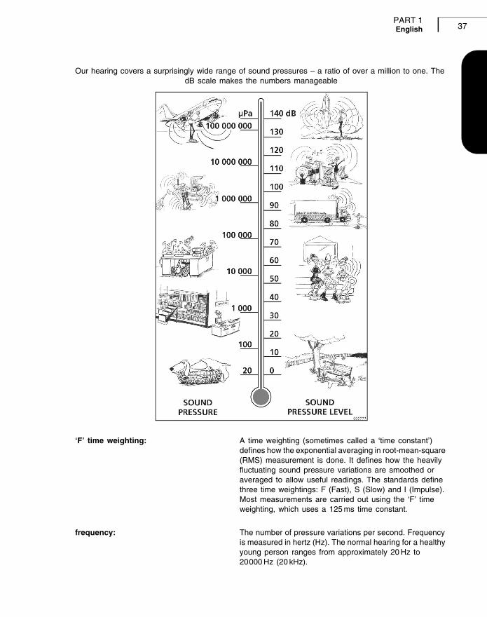
Our hearing covers a surprisingly wide range of sound pressures – a ratio of over a million to one. The dB scale makes the numbers manageable
‘F’ time weighting: A time weighting (sometimes called a ‘time constant’) defines how the exponential averaging in root-mean-square (RMS) measurement is done. It defines how the heavily fluctuating sound pressure variations are smoothed or averaged to allow useful readings. The standards define three time weightings: F (Fast), S (Slow) and I (Impulse). Most measurements are carried out using the ‘F’ time weighting, which uses a 125 ms time constant.
frequency: The number of pressure variations per second. Frequency is measured in hertz (Hz). The normal hearing for a healthy young person ranges from approximately 20 Hz to 20000 Hz (20 kHz).
BE169511.book Page 37 Tuesday, October 28, 2003 10:26 AM

Integrating-averaging Sound Level Meter Type 2240 – User Guide38
frequency weighting: Our hearing is less sensitive at very low and very high frequencies. In order to account for this, weighting filters can be applied when measuring sound. The most commonly used weighting is the ‘A-weighting’, which approximates the human ear’s response to low – medium noise levels. A ‘C-weighting’ curve is also used, particularly when evaluating very loud or very low-frequency sounds.
LAeq: A widely used noise parameter that calculates a constant level of noise with the same energy content as the varying acoustic noise signal being measured. The letter ‘A’ denotes that the A-weighting has been included and ‘eq’ indicates that an equivalent level has been calculated. Hence, LAeq is the A-weighted equivalent continuous noise level.
LAF: The instantaneous sound pressure level. ‘A’ denotes that the A-frequency weighting is used. ‘F’ denotes that the Fast time-weighting is used.
LAFmax: Maximum A-weighted noise level measured with Fast time weighting. It is the highest level of environmental noise occurring during the measurement time. It is often used in conjuction with another noise parameter (for example LAeq) to ensure a single noise event does not exceed a limit.
LCpeak: Maximum peak sound pressure level during a measurment. The ‘C’ frequency weighting is applied. Used for assessing possible damages to human hearing caused by very high short-duration noise levels.
000055
Frequency(Hz)
0
Lp (dB)
10 20 50 100 200 500 1k 2k 5k 10k 20k
–20
–40
–60
AC
BE169511.book Page 38 Tuesday, October 28, 2003 10:26 AM

PART 1English 39
sound: Any pressure variation that the human ear can detect. Just like dominoes, a wave motion is set off when an element sets the nearest particle of air into motion. This motion gradually spreads to adjacent air particles further away from the source. Depending on the medium, sound extends and affects a greater area (propagates) at different speeds. In air, sound propagates at a speed of approximately 340 m/s. In liquids and solids, the propagation velocity is greater – 1500 m/s in water and 5000 m/s in steel.
sound pressure level: The level in decibels of the pressure variation of a sound. See also decibel.
BE169511.book Page 39 Tuesday, October 28, 2003 10:26 AM

Integrating-averaging Sound Level Meter Type 2240 – User Guide40
BE169511.book Page 40 Tuesday, October 28, 2003 10:26 AM