INTEGRATED TRACKING SYSTEM AND …pathfinder.engin.umich.edu/documents/Report-UMCEE-2010...GENERIC...
53
INTEGRATED TRACKING SYSTEM AND FRAMEWORK FOR CONTEXT AWARE ENGINEERING APPLICATIONS By Manu Akula and Prof. Vineet R. Kamat UMCEE Report No 2010-02 Civil and Environmental Engineering Department UNIVERSITY OF MICHIGAN Ann Arbor, MI May 2010 Copyright 2010 by Manu Akula and Prof. Vineet R. Kamat
-
Upload
phungkhuong -
Category
Documents
-
view
219 -
download
1
Transcript of INTEGRATED TRACKING SYSTEM AND …pathfinder.engin.umich.edu/documents/Report-UMCEE-2010...GENERIC...
INTEGRATED TRACKING SYSTEM
AND FRAMEWORK FOR CONTEXT
AWARE ENGINEERING
APPLICATIONS
By
Manu Akula and Prof. Vineet R. Kamat
UMCEE Report No 2010-02
Civil and Environmental Engineering Department
UNIVERSITY OF MICHIGAN
Ann Arbor, MI
May 2010
Copyright 2010 by Manu Akula and Prof. Vineet R. Kamat

ii
ABSTRACT
Evolving technologies such as context aware computing offer significant potential of
improving decision making tasks in several engineering applications by providing
support for tedious and time consuming activities associated with timely and accurate
access to needed information. Bi-directional flow of information relevant to the spatial
context of a mobile user requires continuous and accurate tracking of the user’s position
and orientation. The tracking technology used cannot be dependent on installed
infrastructure because it is not possible to install such infrastructure in every building.
Additionally, a disaster may cause partial or complete damage to the installed
infrastructure itself. The Global Positioning System (GPS) is a convenient option
because it is independent on pre-installed infrastructure; however it fails when the line
of sight to the satellites is obstructed. To overcome this problem, this report presents
research that investigated the development and effectiveness of a ubiquitous location
tracking system based on the integration of Real Time Kinematic Global Positioning
System (RTK-GPS) and Personal Dead Reckoning (PDR) technologies for dynamic
user position tracking. The designed GPS-PDR switching algorithms, along with
experimental results documenting system effectiveness based on path complexity,
length and duration are described. The report also describes a software and hardware
framework developed for implementing complex ubiquitous context-aware computing
applications in civil engineering.

iii
ACKNOWLEDGMENTS
I would like to express my sincere appreciation to Professors Vineet R. Kamat and
Johann Borenstein and my colleagues Suyang Dong and Adam Borrell for their
assistance in the preparation of this report, whose familiarity with various
location tracking technologies were helpful during the programming and
experimental phase of this research undertaking.
I would like to thank my family for their valuable support through my academic
career.
I would also like to thank my friends for their assistance and support, for always
being there to back me up with words of encouragement and constructive
criticism.
Manu Akula
May, 2010
iv
TABLE OF CONTENTS
1
INTRODUCTION 1
1.1
IMPORTANCE OF RESEARCH 1
1.2
RESEARCH OBJECTIVE 2
2
REAL TIME KINEMATIC GLOBAL POSITIONING SYSTEM 4
3
PREVIOUS WORK ON INDOOR TRACKING TECHNOLOGIES 7
4
OVERVIEW OF NON-GPS NAVIGATION WITH PERSONAL
DEAD-RECKONING SYSTEM 15
4.1
INTRODUCTION TO PDR 15
4.2
PDR HARDWARE 16
4.3
PDR DATA PACKETS 17
5
INTEGRATED TRACKING SYSTEM 18
5.1
INTEGRATED TRACKING SYSTEM COMPONENTS 18
5.2
INTEGRATED TRACKING SYSTEM ALGORITHM 19
5.2.1 Principle behind the Integration Algorithm 19
5.2.2 Switching in the Integration Algorithm 19
5.2.3 GPS Corrections to PDR Position 20
5.3
VISUALIZATION OF THE INTEGRATED TRACKING SYSTEM 22
6
VALIDATION EXPERIMENTS 24
6.1
INTRODUCTION TO THE VALIDATION EXPERIMENTS 24
6.2
VALIDATION EXPERIMENTS RESULTS 25
6.3
CONCLUSIONS FROM VALIDATION EXPERIMENTS 28
6.3.1 Advantages of Using an Integrated Tracking System 28
7
GENERIC PLATFORM FOR UBIQUITOUS CONTEXT-AWARE
APPLICATIONS IN CIVIL ENGINEERING 30
7.1
OVERVIEW OF LOCATION TRACKING 30
7.2
OVERVIEW OF ORIENTATION TRACKING 30
7.2.1 Tracking System Hardware 31
7.2.2 The Visual Frustum and the Line of Sight 32

v
7.3
MOBILE USER AVATAR 33
7.3.1 The Mobile User's Body Avatar 33
7.3.2 The Mobile User's Head Avatar 34
7.4
THE ENVIRONMENT IN CONTEXT 35
7.5
THE MOBILE USER'S CONTEXTUAL VIEWS 35
7.5.1 The Bird's Eye Point of View 36
7.5.2 The First Person Point of View 36
8
CONCLUSIONS AND FURTHER STUDY 39
8.1
CONCLUSIONS FROM WORK DONE 39
8.2
FURTHER WORK 39
REFERENCES 44
vi
LIST OF FIGURES
Fig 1 Trimble AgGPS RTK Base 900 tracking system used in this research 5
Fig 2 Indoor GPS transmitter & receiver 7
Fig3 Comparative summary of indoor positioning technologies 8
Fig 4 Approach to RFID based indoor localization 9
Fig 5 Dolphin transmitter and receiver used by Hazas and Hopper in
developing broadband ultrasonic location systems 10
Fig 6 System architecture of low cost location tracking system based on
wireless technologies 11
Fig 7 Indoor positioning systems according to accuracy and range 12
Fig 8 The small sized nIMU developed at the University of Michigan
strapped onto a mobile user’s shoe 16
Fig 9 Definition of the body coordinate system of the PDR 17
Fig 10 The Integrated Tracking System Arrangement 18
Fig 11 Flowchart for the integration algorithm pseudo code 21
Fig 12 ITS algorithm during switch from outdoors to indoors 22
Fig 13 Interface of Widely Integrated Simulation Environment 22
Fig 14 Architecture of Widely Integrated Simulation Environment (WISE) 23
Fig 15 The concept of ‘jump’ in the ITS during a typical walk experiment 24
Fig 16 ITS accuracy and range when operated outdoors and indoors 29
Fig 17 Roll, Pitch and Yaw angles defined for airplanes and a human’s view 30
Fig 18 TCM5 magnetic orientation tracker chip mounted on a helmet 31
Fig 19 Mobile user’s line of sight and viewing frustum 32
Fig 20 The mobile user avatar with the viewing frustum attached to the head
and computational assumptions to capture avatar’s body’s motion 34

vii
Fig 21 Four samples among several different environments loaded as geometric
files on the framework for context aware engineering applications 35
Fig 22 Bird’s Eye Point of View of the mobile user and the Construction Lab in
the G. G. Brown building, University of Michigan, Ann Arbor 36
Fig 23 The First Person View of the mobile user while observing the Construction
Lab in the G.G. Brown building, University of Michigan, Ann Arbor 37
Fig 24 Three types of non-straight motion better captured by the PDR with
heuristic drift correction 40
Fig 25 Architecture of manual position correction in ITS 41

viii
LIST OF TABLES
Table 1 Jumps in ITS co-ordinates for short and simple walks 26
Table 2 Jumps in ITS co-ordinates for short and complex walks 26
Table 3 Jumps in ITS co-ordinates for longer walks 27
Table 4 Jumps in ITS co-ordinates for the six parts of the sustainability test 27
Table 5 Average Jumps in ITS co-ordinates for different walks 28
1
1. INTRODUCTION
1.1 IMPORTANCE OF RESEARCH
Context aware computing is defined as the use of environmental characteristics such as
a user’s location, time, identity, profile and activity that is relevant to the current context.
[3] Context aware computing can thus potentially enable mobile users (e.g. construction
inspectors, firefighters) to leverage knowledge about various context parameters to
ensure that they get highly specific information, pertinent to the decisions at hand. The
relevance for context awareness for mobile users has been demonstrated in several
applications by Aziz et al. [1] The concept of context-aware information delivery centers
around the creation of a user centered mobile dynamic indoor and outdoor work
environment, which has the ability to deliver relevant information to on-site mobile users
by intelligent interpretation of their characteristics in space and time so that they can
take more informed decisions. [12] Context awareness is of great value for civil
engineering inspectors, emergency responders, security and military personnel. For
example, tracking civil engineers during post disaster assessments, or while conducting
bridge inspection reports, can allow bi-directional flow of streamlined information and
thereby improve the efficiency of the decision making processes. Bridge inspections are
currently documented manually but will be done virtually in the near future. If a bridge
inspector looking at a particular element of the structure wants to report data regarding
the status of the structure, s/he can ‘pin’ the report in the form of a suitable data file
(.doc, .txt, .jpeg, .avi, etc.) to the element in context in a virtual model of the bridge
under consideration. If the inspector is looking at a particular element of the structure
and wants to read all the data corresponding to the element, the inspector can ‘tap’ into
a database and retrieve the necessary information depending on his/her context.

2
Context-aware applications can be used in providing support to complex, tedious and
time consuming tasks. Civil engineers, fire fighters, military personnel and a host of
other professionals stand to benefit from context-aware applications as it makes bi-
directional flow of information more efficient and relevant based on a mobile user’s
context.
1.2 RESEARCH OBJECTIVE
To implement context aware support applications we must be able to track a user’s
position and orientation continuously and accurately. The Global Positioning System
(GPS) tracks users accurately and continuously in an environment where there is a
direct line of sight to the satellites. However, when there is no direct line of sight, the
system fails. In recent times, cars have been using GPS to navigate. However, when a
car enters a long tunnel, the GPS signal is lost and cannot track the location of the car
on its own. To overcome this deficiency, some cars have a GPS tracking system that is
complemented by an Inertial Navigation Unit (INU) mounted on the wheels. The INU
tracks the motion of the car via. its orientation and the number of rotations of the car’s
wheel whenever the GPS signal is lost. This ensures that the vehicle is tracked
continuously even in a GPS deficient environment. GPS can also be used to track a
moving person in an environment where there is a direct line of sight with the satellites
to acquire a position via GPS. The word ‘outdoors’ is used to describe such an
environment in this report unless specifically mentioned otherwise. The word ‘indoors’ is
used to describe all environment where GPS tracking is not possible due to a lack of
communication with the satellites. There are several ‘indoor’ tracking technologies
available that help in tracking a mobile user continuously and accurately in a GPS
denied environment as described in detail in chapter 3. However, most of these tracking

3
technologies are dependent on pre-installed infrastructure and pre-calibrated data. The
research described in this report is focused on developing an Integrated Tracking
System that ubiquitously tracks a mobile user’s position both indoors and outdoors
independent of installed infrastructure. This is done by integrating GPS with a suitably
chosen indoor tracking technology to complement each other. In general, on a
construction site and other dynamically changing environment where the mobile user
shifts his/her location from indoors to outdoors and vice versa without prior knowledge
of whether the user is within the range of particular tracking technology, it is of utmost
importance that the Integrated Tracking System seemingly translates automatically from
an outdoor tracking technology to an indoor tracking technology without any prompting
from the mobile user.
Another objective of the research is to develop the prototype of a basic platform for
visualizing a mobile user’s context in his/her environment in which the user is changing
his/her position and orientation. A dynamic user-viewpoint tracking scheme has been
designed and implemented in which mobile users’ spatial context is defined not only by
their position (i.e. location), but also by their three-dimensional head orientation (i.e. line
of sight), thereby significantly increasing accuracy in the identification of a user’s spatial
context than is possible by tracking position alone. Based on this framework, a
prototype application was developed using GPS, Personal Dead Reckoning (PDR) and
magnetic orientation tracking devices to track a user’s dynamic viewpoint in different
environments. The framework developed in this research can be used as a base for
developing several context-aware applications in civil engineering.

4
2. REAL TIME KINEMATIC GLOBAL POSITIONING
SYSTEM
The Global Positioning System (GPS) is a space-based global navigation satellite
system that provides reliable location information in all weather at all times and
anywhere on earth where there is an unobstructed line of sight to four or more GPS
satellites. It is maintained by the United States government and is freely accessible by
anyone with a GPS receiver.
Location tracking applications based on GPS are available at several levels based on
the accuracy required by the users. At the personal level, there are several GPS
tracking devices available in the market. Hand held GPS receivers, with replaceable
batteries that can run them for several hours, are suitable for tracking users
during hiking, bicycle touring and other activities far from an electric power source. In
recent years, one of the most popular GPS based tracking application has been the
commercially available Personal Navigation Assistant - a portable electronic product
which combines a positioning capability (through GPS) and navigation functions.
Several different versions of the Personal Navigation Assistant have been developed by
companies like Garmin, TomTom, Navman and Magellan. These systems use GPS at a
personal level and have relatively low accuracy, typically within the range of two to four
meters.
As mentioned in the previous chapters some high end Personal Navigation Assistants
have the capability to track the vehicles even when GPS is unavailable. Such situations
occur typically when a vehicle enters a tunnel or an urban canyon where there is no
direct line of sight to the GPS satellites. This is accomplished by integrating the GPS
positioning system with an Inertial Navigation Unit that tracks the vehicle in a GPS
denied environment. The idea behind the Integrated Tracking System described in this

5
report is based on similar principles. However, the GPS units used by the Personal
Navigation Assistants are typically of lower accuracy than what is desired by context-
aware engineering applications.
Fig 1: Trimble AgGPS RTK Base 900 tracking system used in this research
The GPS system used in this research as a component of the Integrated Tracking
System is a survey level Trimble AgGPS RTK Base 900 system incorporated with Real
Time Kinematic technology. Real Time Kinematic (RTK) satellite navigation is a
technique used in land survey and in hydrographic survey based on the use of carrier
phase measurements of the GPS where a single reference station provides the real-
time corrections, providing up to centimeter-level accuracy. The typical nominal
accuracy for these RTK-GPS systems is 1 centimeter horizontally and 2 centimeters
vertically. The RTK-GPS has the ability to track a mobile user continuously and
accurately as long as the mobile user is outdoors. However, when the user moves into a
GPS denied indoor environment, we must rely on an indoor tracking technology that is
to be incorporated in the Integrated Tracking System to complement the RTK-GPS.
Several such indoor tracking technologies, described in the next chapter, were looked at
during the course of this research. The Personal Dead Reckoning System described in
6
chapter 4 was found to be the most suitable system to be incorporated in the Integrated
tracking System due to reasons described in the next two chapters.

7
3. PREVIOUS WORK ON INDOOR TRACKING
TECHNOLOGIES
In recent years, the need for indoor localization has been rapidly expanding in many
fields and currently offers significant potential on construction sites in particular.
However, unlike outdoor areas, the indoor environment imposes different challenges on
location discovery due to the dense multipath effect and building material dependent
propagation effect. There are many potential technologies and techniques that have
been suggested to offer the same functionality as a GPS indoors, such as Wireless
Local Area Networks (WLAN), Ultra-Wide Band (UWB) and Indoor GPS. By tagging
users with appropriate receivers/tags and deploying a number of nodes (access points,
receivers, transmitters, etc.) at fixed positions indoors, the location of tagged users can
conceptually be determined and continuously tracked by fingerprinting and triangulation.
Fig 2: Indoor GPS transmitter & receiver [6]
A detailed comparison of the WLAN, UWB and Indoor GPS systems has also been
done in a recent study by Kamat and Khoury. [6] The research studied and compared
three different wireless technologies (WLAN, UWB and Indoor GPS), that can be used

8
for tracking mobile users on indoor construction sites. In order to evaluate and compare
the technical features of these technologies and their applicability in a context-aware
information delivery framework, several experiments were conducted at the University
of Michigan, Disaster City (Texas A&M University), and NIST. Based on the
experiments, it was found that the decision on using one technology over another
should be based on important technical criteria (e.g. calibration, line of sight, etc.) in
addition to other logistic issues such as availability, the prevailing legal situation (e.g.
permitted bandwidth), and the associated implementation costs. However, based on the
circumstances expected in the intended deployment environment (i.e. indoor
construction sites), the Indoor GPS positioning technology was found to offer the most
promise due to the low level of uncertainty in the reported user position (1 to 2 cm)
compared to that of WLAN (1.5 to 2 m) and UWB (10 to 50 cm). [6]
Fig 3: Comparative summary of indoor positioning technologies [6]
RFID also has the capability to locate users in an indoor environment. In most of the
research studies on using radio frequency for indoor localization, typically some
readers/receivers are placed at fixed locations and a tag/transmitter is attached to a
mobile object or a person. A converse approach has also been pursued by Pradhan,
Ergen and Akinci. [11] Instead of multiple readers, multiple tags were placed at fixed
locations and a reader is carried by the person, who was to be located in the building

9
with respect to the tags. The study developed an approach to assess the capability of
RFID in helping to locate a user using RFID signal strength values and conducted
experiments to test the approach under real operating conditions. The research
identified a set of requirements for guidance (directional reliability, time invariance, and
spatial accuracy and precision) and evaluated the requirements for RFID signal strength
approach. The approach in this research (using one reader to locate a user) was found
to be 93% accurate for 10.7 m of precision. [11]
Fig 4: Approach to RFID based indoor localization [11]
Ultrasonic location systems are a popular solution for the provision of indoor positioning
data. Applications include enhanced routing for wireless networks, computer-aided
navigation, and location-sensitive device behavior. However, using narrowband
transducers in ultrasonic location systems result in several limitations. Hazas and
Hopper [4] have developed and characterized ultrasonic indoor location systems that
use broadband ultrasonic transmitter and receiver units. Their research dealing with the
utilization of broadband and narrowband units to construct two positioning systems with

10
different architectures serves to highlight and affirm the concrete, practical benefits of
broadband ultrasound for locating people and devices indoors. Hazas and Hopper [4]
have demonstrated that ultrasonic indoor location systems based on broadband units
have the potential for significantly higher performance in a number of aspects of system
operation than their narrowband counterparts because broadband systems can utilize
spread spectrum, multiple access techniques in their ranging signals. [4]
Fig 5: Dolphin transmitter and receiver used by Hazas and Hopper in developing
broadband ultrasonic location systems [4]
Broadband ultrasonic systems have been shown to have a number of advantages over
their narrowband counterparts. The performance enhancements for location systems
using broadband ultrasound include enhanced performance in noise robustness,
increased update rates, low latency positioning (this means location updates for multiple
people and devices can be nearly simultaneous) and enhanced identification encoding
(transmitter signals can be uniquely identified at the receiver since broadband signals
have a much greater capacity to carry information). [4]

11
Mautz [7] describes an automatic, low-cost system that exploits wireless communication
technology to enable continuous tracking of the location of devices, and consequently
users carrying those devices, in all environments (indoors and outdoors). The research
describes the development of a wireless sensor network that involves system design,
digital signal processing, protocol development, extraction of ranges and localization
including a high level strategy for the positioning function based on an ad-hoc geodetic
network positioning method which is evaluated on issues of accuracy, quality and
reliability of the node positions. It was demonstrated that it is possible to achieve a
position deviation that is of the size of the ranging error. [7]
Fig 6: System architecture of low cost location tracking system based on wireless
technologies [7]
Mautz [7] indicates that tracking of devices and users needs to have full coverage in
different environments – indoors as well as outdoors. Consequently, the system should
12
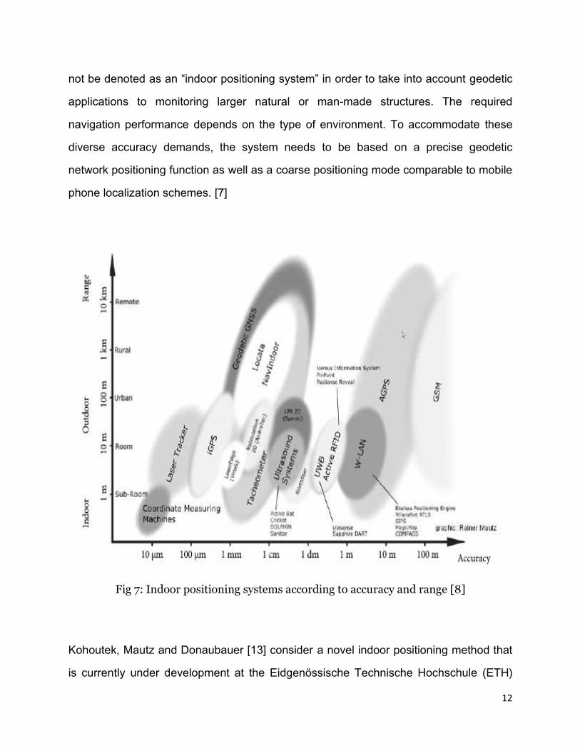
not be denoted as an “indoor positioning system” in order to take into account geodetic
applications to monitoring larger natural or man-made structures. The required
navigation performance depends on the type of environment. To accommodate these
diverse accuracy demands, the system needs to be based on a precise geodetic
network positioning function as well as a coarse positioning mode comparable to mobile
phone localization schemes. [7]
Fig 7: Indoor positioning systems according to accuracy and range [8]
Kohoutek, Mautz and Donaubauer [13] consider a novel indoor positioning method that
is currently under development at the Eidgenössische Technische Hochschule (ETH)
13
Zurich. The method relies on a digital spatio-semantic interior building model CityGML
and a Range Imaging sensor. In contrast to common indoor positioning approaches, the
procedure presented here does not require local physical reference infrastructure, such
as WLAN hot spots or reference markers. However, this method depends on image
sensing and cannot be relied upon especially a dynamically changing environment, for
instance when a building is partially or fully damaged, we cannot expect to use an
image sensing localization system to be reliable. Mautz [8] compares several indoor
positioning systems including AGNSS & high sensitivity receivers, pseudolites using
GNSS signals, laser tracking, iGPS and ultrasonic systems. [8]
The main drawback of the aforementioned indoor tracking technologies is their
dependency on pre-installed infrastructure and pre-calibration for fingerprinting. Also,
most technologies are environment (outdoors and indoors) specific. Such dependency
makes them unreliable in a dynamic environment because we cannot expect every
building to have pre-installed infrastructure and pre-calibration done for fingerprinting.
Also, in a dynamically changing environment, where a mobile user moves from outdoors
to indoors and vice versa changing his/her environment, it is obviously beneficial to
have a comprehensive location tracking system that can be used reliably irrespective of
his/her environment. Moreover, the pre-installed infrastructure may be partially or fully
damaged in case of a post disaster assessment scenario. It is therefore of utmost
importance that we do not rely on such indoor tracking technologies and there is a need
to use indoor tracking technologies that are independent on pre-installed infrastructure
and pre-calibration techniques. To overcome this we recommend the use of Personal
Dead Reckoning (PDR) tracking systems for indoor tracking. PDR systems are based
on Inertial Navigation and are independent of pre-installed infrastructure. Although less
accurate than WLAN, UWB and Indoor GPS, they provide us with sufficient accuracy

14
that degrades gracefully with extreme modes of legged locomotion. Chapter 4 of this
report describes the PDR system used in this research in greater detail.

15
4. OVERVIEW OF NON-GPS NAVIGATION WITH
PERSONAL DEAD-RECKONING SYSTEM
4.1 INTRODUCTION TO PDR
The PDR system used in this research is the Personal Odometry System (POS)
developed by Ojeda and Borenstein [9] at the University of Michigan, Ann Arbor. The
POS uses data from the accelerometers and gyroscopes in the Inertial Measurement
Unit (IMU) sensor attached to the user’s boots. From this data the POS computes the
complete trajectory of the boot during each step.
The POS offers the following features:
o Linear Displacement: This is the most important and most basic function of the
system – the measurement of distance traveled, but without measuring the
direction. This function works like the odometer of a car, which also does not
measure the direction of travel. The POS performs this function with an error of
about 2% of distance traveled; regardless of duration or distance. The POS is
also indifferent to the stride length and pace, as well as to the gait. There is also
no need for calibration or fitting the system to the walking pattern of a specific
user. The accuracy of the PDR system, however, degrades gracefully with
extreme modes of legged locomotion, such as running, sideways motion, walking
backwards, jumping, and climbing. [10]
o Position Estimation: This capability includes odometry as well as the
measurement of direction. Position estimation allows the system to determine the
subject’s actual location in terms of x, y, and z coordinates, relative to a known
starting location. The measurement of direction is based on the use of
16
gyroscopes, which are known to have drift, just as accelerometers do. However,
the correction method that is applied to the accelerometers in not effective for
gyros. Therefore, the system is currently susceptible to the accumulation of
heading errors over time. The system also measures vertical position, but less
accurately so. [10]
The main drawback of the PDR system is the accumulated error that grows with the
distance travelled by the mobile user. To overcome this, we have developed algorithms
that integrated PDR positioning systems with GPS systems that will correct the drifting
error accumulated over time.
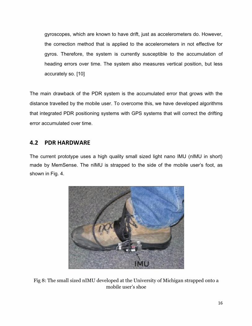
4.2 PDR HARDWARE
The current prototype uses a high quality small sized light nano IMU (nIMU in short)
made by MemSense. The nIMU is strapped to the side of the mobile user’s foot, as
shown in Fig. 4.
Fig 8: The small sized nIMU developed at the University of Michigan strapped onto a
mobile user’s shoe
17
The IMU is connected to a tablet-style laptop computer through an RS-422
communication port. The IMU is powered using a small external 7.8-Volt Lithium
Polymer battery, making the whole system portable. The computer runs the Linux
operating system patched with a real-time extension and our algorithm runs in real-time.
[9]
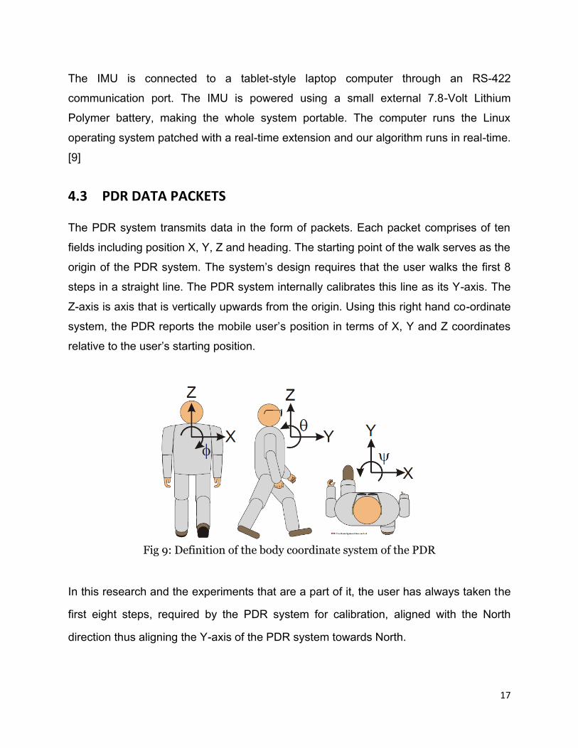
4.3 PDR DATA PACKETS
The PDR system transmits data in the form of packets. Each packet comprises of ten
fields including position X, Y, Z and heading. The starting point of the walk serves as the
origin of the PDR system. The system’s design requires that the user walks the first 8
steps in a straight line. The PDR system internally calibrates this line as its Y-axis. The
Z-axis is axis that is vertically upwards from the origin. Using this right hand co-ordinate
system, the PDR reports the mobile user’s position in terms of X, Y and Z coordinates
relative to the user’s starting position.
Fig 9: Definition of the body coordinate system of the PDR
In this research and the experiments that are a part of it, the user has always taken the
first eight steps, required by the PDR system for calibration, aligned with the North
direction thus aligning the Y-axis of the PDR system towards North.
18
5. INTEGRATED TRACKING SYSTEM
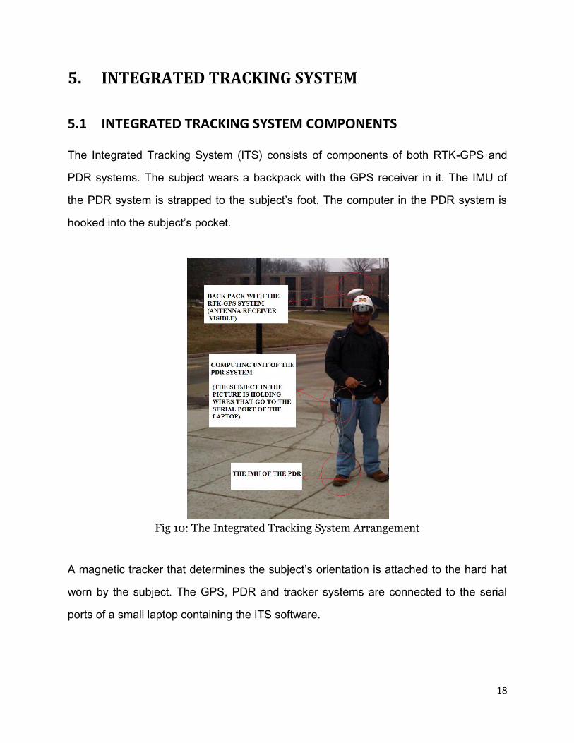
5.1 INTEGRATED TRACKING SYSTEM COMPONENTS
The Integrated Tracking System (ITS) consists of components of both RTK-GPS and
PDR systems. The subject wears a backpack with the GPS receiver in it. The IMU of
the PDR system is strapped to the subject’s foot. The computer in the PDR system is
hooked into the subject’s pocket.
Fig 10: The Integrated Tracking System Arrangement
A magnetic tracker that determines the subject’s orientation is attached to the hard hat
worn by the subject. The GPS, PDR and tracker systems are connected to the serial
ports of a small laptop containing the ITS software.
19
5.2 INTEGRATED TRACKING SYSTEM ALGORITHM
5.2.1 Principle behind the Integration Algorithm
The ITS records the mobile user’s current location as dictated by the RTK-GPS and the
PDR separately. However, the coordinate system used by the PDR is different from the
World Geodetic System 84 (WGS 84) latitude, longitude, altitude coordinate system
used by the RTK-GPS. To resolve this issue, the ITS uses Vincenty’s Forward Pass
Algorithm for WGS 84 to convert the user’s location from a local X, Y, Z coordinate
system to a location on the WGS 84 - latitude, longitude, altitude coordinate system.
The accuracy of RTK-GPS (3 to 5 centimetres) is much higher than the accuracy of the
PDR. Also, the accuracy of the PDR decreases with the distance travelled by the mobile
user. As a result the position of the user as dictated by the RTK-GPS is almost always
inevitably more accurate than the position dictated by the PDR. The principle behind
determining the ITS co-ordinates is that RTK-GPS co-ordinates, if available, always
take precedence over the PDR co-ordinates.
5.2.2 Switching in the Integration Algorithm
When the mobile user enters a GPS denied environment such as indoor structures,
urban canyons, etc. the ITS no longer receives the mobile user’s position as dictated by
the RTK-GPS system. When the ITS loses connectivity with the RTK-GPS system, the
ITS ensures that the position of the mobile user is the position as dictated by the PDR
system adjusted for drift correction. These adjustments are described in detail in
Section 5.2.3.
The ITS continues to locate the mobile user’s position as dictated by the PDR for the
entire duration that the user is in the GPS denied environment. As soon as the mobile
user steps out of the GPS denied environment and receives a signal from the RTK-GPS

20
system, the ITS switches back and the ITS mobile user’s location is dictated once again
by the RTK-GPS system. The integration algorithm of the ITS seamlessly switches
between the RTK-GPS and PDR systems when required and thus provides the most
reliable location of the mobile user continuously and accurately in both indoor and
outdoor environments. The accuracy of the PDR degrades gracefully with the distance
travelled by the mobile user and this is reflected in the accuracy of the ITS when the
user is in a GPS denied environment for longer durations.
5.2.3 GPS Corrections to PDR Position
The main drawback of the PDR system is that it accumulates drift error over time. This
drift error is accumulated irrespective of whether the GPS is available or not. The PDR
position is ‘corrected’ to the RTK-GPS position by the ITS as long as the RTK-GPS
signal is available. The correction is equal to the different in position between the RTK-
GPS and PDR positions. In effect, as long as the RTK-GPS signal is available the
corrected PDR position is the same as the RTK-GPS position. This correction would
eliminate all drift accumulated in the PDR and therefore the ITS as long as the RTK-
GPS is available. Once the user loses contact with the RTK-GPS signal, the correction
applied is equal to the difference in the last known RTK-GPS location and its
corresponding PDR location. From that point onwards, till the RTK-GPS is recovered,
the same correction is applied to the PDR location. This in effect means that the only
drift that will be accumulated by the PDR would be the drift accumulated during the
mobile user’s walk in a GPS denied environment. The constant correction being applied
by the ITS to the PDR location in GPS denied environment makes sure that it nullifies
the effect of drift accumulated in the user’s walk till the very last time the user has
entered the particular GPS denied environment. Once the user steps out of the GPS
denied environment, the ITS regains the RTK-GPS signal, however, this may not
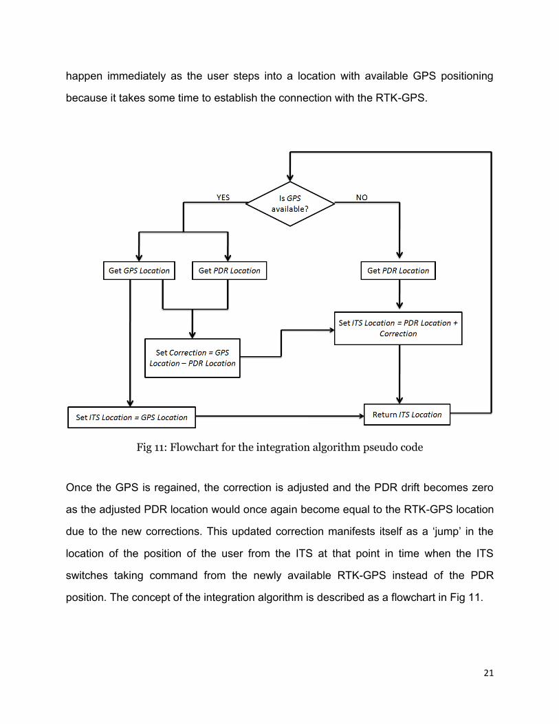
21
happen immediately as the user steps into a location with available GPS positioning
because it takes some time to establish the connection with the RTK-GPS.
Fig 11: Flowchart for the integration algorithm pseudo code
Once the GPS is regained, the correction is adjusted and the PDR drift becomes zero
as the adjusted PDR location would once again become equal to the RTK-GPS location
due to the new corrections. This updated correction manifests itself as a ‘jump’ in the
location of the position of the user from the ITS at that point in time when the ITS
switches taking command from the newly available RTK-GPS instead of the PDR
position. The concept of the integration algorithm is described as a flowchart in Fig 11.
22
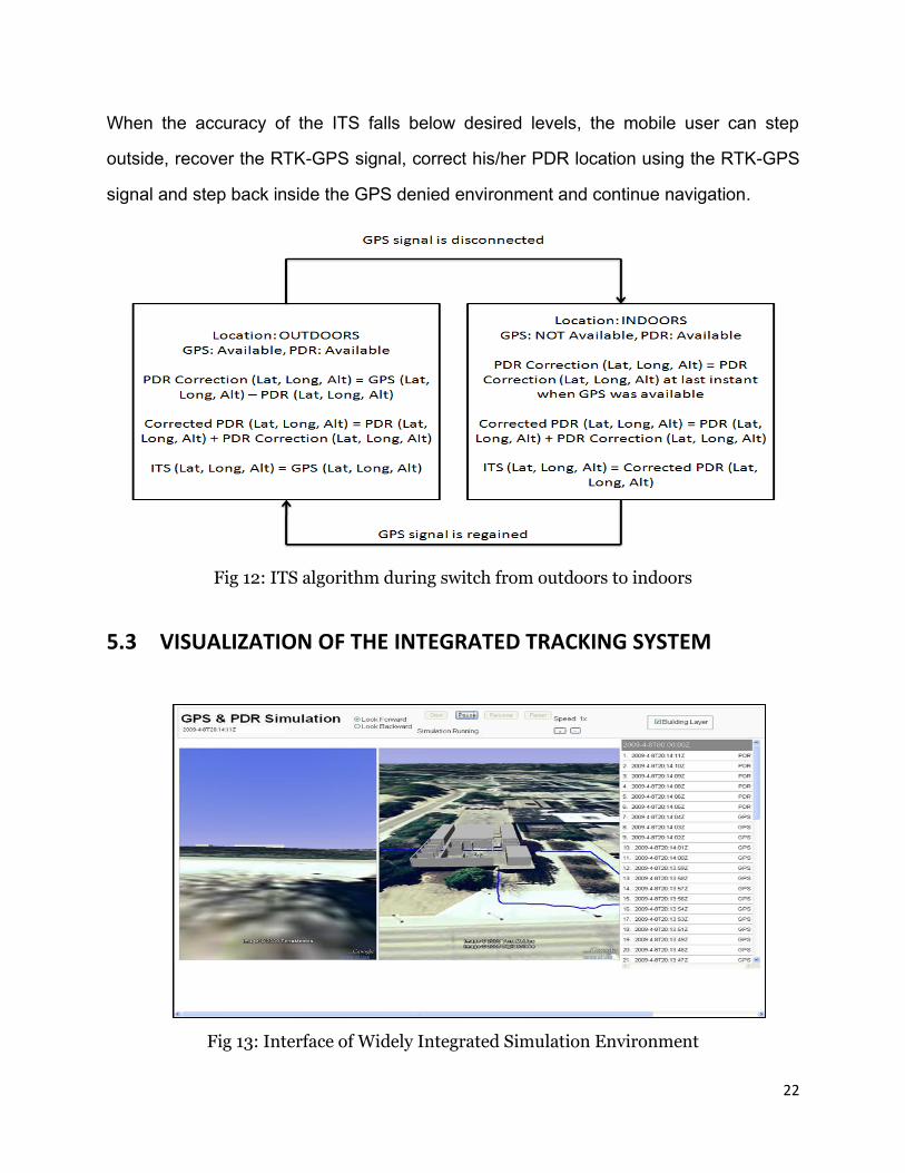
When the accuracy of the ITS falls below desired levels, the mobile user can step
outside, recover the RTK-GPS signal, correct his/her PDR location using the RTK-GPS
signal and step back inside the GPS denied environment and continue navigation.
Fig 12: ITS algorithm during switch from outdoors to indoors
5.3 VISUALIZATION OF THE INTEGRATED TRACKING SYSTEM
Fig 13: Interface of Widely Integrated Simulation Environment

23
The ITS is visualized on Widely Integrated Simulation Environment (WISE) that was
developed at the University of Michigan by Suyang Dong and Vineet R. Kamat. The
WISE interface displays the location of the user in a Google Earth environment. The
mobile user’s path is recorded by the ITS along with a record which component, RTK-
GPS or PDR, dictates the particular portion of the path as a KML file in real time. This
KML is replayed on the server side that is read by a HTTP request. The path is
displayed as an animation in the Google Earth API. On the right hand side of the GUI,
there is a counter that displays the position in terms of latitude, longitude, altitude of the
user’s current position as displayed in the post process animation. WISE has features
that will allow the user to view the simulation at 2, 4 and 8 times the natural rate. It also
has options to pause and retrieve the position of the user at any point on the path.
Fig 14: Architecture of Widely Integrated Simulation Environment (WISE)

24
6. VALIDATION EXPERIMENTS
6.1 INTRODUCTION TO THE VALIDATION EXPERIMENTS
The experimental results obtained with the ITS described in the foregoing section.
These results focus on three different types of experiments (1) short and simple walks,
(2) short and complex walks and (3) longer walks.
Fig 15: The concept of ‘jump’ in the ITS during a typical walk experiment
Short and simple walks
Relatively simple walks having duration between 3 to 5 minutes (indoors) are classified
as short walks. These walks involved few turns and almost no abrupt disturbances in
motion.

25
Short and complex walks
Relatively complex walks having duration between 3 to 5 minutes (indoors) are
classified as short and complex walks. These walks involved relatively more turns,
abrupt disturbances in motion, climbing and sideward motion.
Longer walks
Relatively complex walks having duration over 5 minutes (indoors) are classified as
longer walks. These involved relatively more turns, abrupt disturbances in motion,
climbing and sideward motion.
To test the sustainability of the ITS we conducted a very long walk (over 30 minutes).
The walk involved a lot of turns, abrupt disturbances in motion, climbing and sideward
motion in order to simulate a mobile user’s natural motion in a complex environment.
The walk was divided into 6 parts; 3 parts were of a short duration, less than 5 minutes
indoors, and rest were longer. At the end of each part, the user walked out of the
building, recovered the RTK-GPS correcting the error in the ITS and continued his/her
walk into the building.
6.2 VALIDATION EXPERIMENTS RESULTS
Short and simple walks
Table 1 summaries the “jumps” in the user’s position (ITS co-ordinates) when the user
steps out of the building as GPS is recovered. The “jump” is the difference in the last
dominant corrected PDR co-ordinates and the first recovered GPS co-ordinates. This is
equal to the accumulated error of the PDR during the time spent by the user inside the
building (i.e. when) PDR corrections were not being updated instantaneously using the
RTK-GPS).

26
Walk 1 Walk 2 Walk 3 Walk 4
Last dominant PDR(Lat) 42.29406754 42.29469283 42.293688 42.29369639
Last dominant PDR(Long) -83.71153664 -83.71147129 -83.71345745 -83.71349191
Recovered GPS (Lat) 42.29407585 42.29469192 42.29368167 42.29368364
Recovered GPS (Long) -83.71152177 -83.711455 -83.71345969 -83.71347379
Jump (meter) 1.536 1.347 0.727 2.058
Table 1: Jumps in ITS co-ordinates for short and simple walks
Short and complex walks
Table 2 summarizes the “jumps” in the user’s ITS position co-ordinates when the GPS
is recovered.
Walk 1 Walk 2 Walk 3 Walk 4
Last dominant PDR(Lat) 42.29369813 42.29369732 42.29370127 42.29369917
Last dominant PDR(Long) -83.7134819 -83.71344807 -83.71345722 -83.7134601
Recovered GPS (Lat) 42.29368493 42.29367664 42.29367843 42.29367342
Recovered GPS (Long) -83.7134585 -83.71346203 -83.71345254 -83.7134486
Jump (meter) 2.423 2.571 2.566 3.013
Table 2: Jumps in ITS co-ordinates for short and complex walks
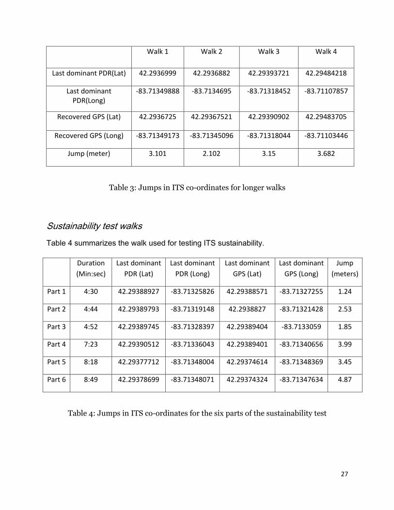
Longer walks
Table 3 summarizes the “jumps” in the user’s ITS position co-ordinates when GPS is
recovered.
27
Walk 1 Walk 2 Walk 3 Walk 4
Last dominant PDR(Lat) 42.2936999 42.2936882 42.29393721 42.29484218
Last dominant PDR(Long)
-83.71349888 -83.7134695 -83.71318452 -83.71107857
Recovered GPS (Lat) 42.2936725 42.29367521 42.29390902 42.29483705
Recovered GPS (Long) -83.71349173 -83.71345096 -83.71318044 -83.71103446
Jump (meter) 3.101 2.102 3.15 3.682
Table 3: Jumps in ITS co-ordinates for longer walks
Sustainability test walks
Table 4 summarizes the walk used for testing ITS sustainability.
Duration
(Min:sec)
Last dominant
PDR (Lat)
Last dominant
PDR (Long)
Last dominant
GPS (Lat)
Last dominant
GPS (Long)
Jump
(meters)
Part 1 4:30 42.29388927 -83.71325826 42.29388571 -83.71327255 1.24
Part 2 4:44 42.29389793 -83.71319148 42.2938827 -83.71321428 2.53
Part 3 4:52 42.29389745 -83.71328397 42.29389404 -83.7133059 1.85
Part 4 7:23 42.29390512 -83.71336043 42.29389401 -83.71340656 3.99
Part 5 8:18 42.29377712 -83.71348004 42.29374614 -83.71348369 3.45
Part 6 8:49 42.29378699 -83.71348071 42.29374324 -83.71347634 4.87
Table 4: Jumps in ITS co-ordinates for the six parts of the sustainability test

28
6.3 CONCLUSIONS FROM VALIDATION EXPERIMENTS
As tested to date, the ITS is very accurate for tracking smooth walks. The accuracy of
the ITS, reflects that of the PDR and degrades gracefully with both path complexity and
time spent indoors. Once the accumulated drift in the ITS starts to overshoot the
satisfactory level the user needs to step outdoors and recover the GPS signal to reset
the corrections. Depending on the degree of accuracy required by the context-aware
application, the required frequency of corrections can be determined.
The average “jump” in the ITS co-ordinates when the GPS is recovered increases with
the time spent indoors. This is expected because the corrections to the PDR are not
being updated instantaneously due to RTK-GPS being unavailable. Table 9 summarizes
the experimental results.
Type of walk Average Duration Indoors Average jump
Short and simple walks 3 minutes 45 seconds 1.4 meters
Short and complex walks 3 minutes 45 seconds 2.6 meters
Longer walks 6 minutes 15 seconds 3 meters
Table 5: Average Jumps in ITS co-ordinates for different walks
6.3.1 Advantages of Using an Integrated Tracking System
The Integrated Tracking System (ITS) described in this work is truly independent of
environment. The ITS can adapt and translate seamlessly from an outdoor environment
to an indoor environment and vice versa. Also, it can be implemented in a dynamically
changing environment as it doesn’t depend on any ‘image reorganization’. The ITS is
independent of pre-installed infrastructure and has absolutely no requirements for pre-

29
calibration or fingerprinting – process common in indoor localization technologies. This
would reduce tremendous amount of time and effort and would eliminate the need for
data storage. The ITS can be implemented in a post disaster scenario, where traditional
localization systems may fail due to partial or full damage to the preinstalled
infrastructure. The ITS developed in this research is a truly robust, reliable system that
determines a user’s location continuously with a high degree of accuracy.
The ITS is a light weight mobile, flexible and easy to use tracking device that can be
used to help locate mobile users in dynamically changing environments. The ITS can be
tremendously useful for inspectors, emergency response crews, military personnel, etc.
One specific application is described in the following chapter.
Fig 16: ITS accuracy and range when operated outdoors (red) and indoors (green)
30
7. GENERIC PLATFORM FOR UBIQUITOUS CONTEXT-
AWARE APPLICATIONS IN CIVIL ENGINEERING
We have been developing a generic platform for ubiquitous context aware applications
with some inherent elementary features. The platform can be modified in the future and
can be tailored to suit the specific context aware application required.
7.1 OVERVIEW OF LOCATION TRACKING
The ITS described in the previous chapters dictates the mobile user’s location, in terms
of latitude (x), longitude (y) and altitude (z), to the platform. However, these three
measurements are not enough to define a user’s context.
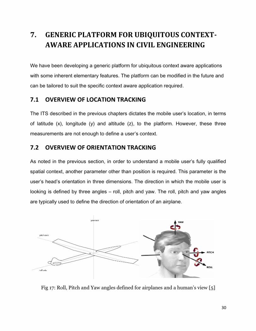
7.2 OVERVIEW OF ORIENTATION TRACKING
As noted in the previous section, in order to understand a mobile user’s fully qualified
spatial context, another parameter other than position is required. This parameter is the
user’s head’s orientation in three dimensions. The direction in which the mobile user is
looking is defined by three angles – roll, pitch and yaw. The roll, pitch and yaw angles
are typically used to define the direction of orientation of an airplane.
Fig 17: Roll, Pitch and Yaw angles defined for airplanes and a human’s view [5]

31
Yaw represents the rotation in the horizontal plane, pitch is the rotation in the vertical
plane parallel to the forward direction, and roll is the rotation in the vertical plane
perpendicular to the forward direction.
7.2.1 Tracking System Hardware
The orientation tracker is a TCM5 magnetic orientation tracker. It includes a built-in
compass, and employs solid-state magnetic field sensors which measure compass
heading through a full 360 degrees of rotation. The tracker employs proprietary hard
and soft iron correction algorithms to calibrate out magnetic anomalies for repeatable,
high resolution measurement in challenging environments.
The tracker is enclosed in an aluminum container and is placed at the lowest point on
the user’s helmet, directly above the forehead. This ensures that the orientation of the
tracker is as close to the line of sight of the user as possible.
Fig 18: TCM5 magnetic orientation tracker chip (left) mounted on a helmet (right)
The ITS measure’s a user’s position as longitude (x), latitude (y) and altitude (z) while
the magnetic tracker measures the orientation of the user’s head, and consequently the
line of sight, in the form of roll, pitch and yaw. These six measurements fully define the
user’s context at any point of time.

32
7.2.2 The Visual Frustum and the Line Of Sight
The line of sight in itself is not a complete representation of the region of space visible
to the mobile user. The region of real space visible to a mobile computing user can be
conceptually thought of to be similar to an avatar’s viewpoint in a computer graphics
application or virtual reality world. In a computer graphics world (e.g., visual simulation),
the region of visible virtual space is called the viewing frustum or view frustum, and is
typically shaped as a frustum of a rectangular pyramid. [11] Based on the concept of the
viewing frustum, and the six measurements that define the user’s context (position and
orientation) we mathematically derived the formulation for the region of space visible to
a mobile computing user. Objects closer to the user than the near plane or beyond the
far plane are assumed to be out of sight and context. Typically, the near plane is chosen
close to the user’s viewpoint and the far plane is placed infinitely far away so all objects
within the frustum are considered to be of interest regardless of their distance from the
user.
Fig 19: Mobile user’s line of sight and viewing frustum

33
The platform has a provision for adjusting the near and far plane distances at any point
in the simulation. A large value for the far plane distance would typically represent the
situation where the far plane is at infinity. The platform can be modified by using ray
casting algorithms to identify objects that fall within the viewing frustum and therefore
are in the mobile user’s context.
7.3 MOBILE USER AVATAR
The platform has a mobile user’s avatar in the virtual world to represent the mobile user
and his/her motion. To capture the complexity of human motion, the avatar is divided
into two components – the avatar head and the avatar body. There is an option provided
to scale the avatar of the user based on the height of the mobile user using the system.
7.3.1 The Mobile User’s Body Avatar
The mobile user’s body is modeled as an ac3d CAD model. The body’s position is
determined by the ITS’s coordinates in the form of latitude (x), longitude (y) and altitude
(z). As described previously, the height of the body’s avatar can be scaled based on the
height of the mobile user.
The user’s body orientation can be captured by assuming that the body is oriented in
the direction of the user’s motion. If the previous position of the user can be indicated by
the vector P1 and the current position vector of the user can be indicated by P2, then
the direction of orientation of the user’s body is defined by the difference in the position
vectors P2 and P1, in the direction of motion (i.e., P1 to P2).

34
Fig 20: The mobile user avatar with the viewing frustum attached to the head (left) and
computational assumptions to capture avatar’s body’s motion (right)
The shortcoming of this approximation done in order to simplify the body’s motion is that
we cannot capture sideward or backward motion. However, this minor shortcoming
helps simplify the process of capturing the motion of the user in the simulation.
7.3.2 The Mobile User’s Head Avatar
The user’s head position is determined by the ITS’s position. However, it is set at a fixed
distance above the user’s body’s avatar. This fixed distance is a function of the user’s
height. The orientation of the user’s head is determined by the orientation of the tracker.
The viewing frustum is attached to the head’s avatar, just between the eyes in the
virtual environment.

35
7.4 THE ENVIRONMENT IN CONTEXT
The framework allows for the environment of the mobile user to be replicated in the
virtual world by loading the appropriate geometric file. The platform has the ability to
load any file format for which there is a plugin in OpenSceneGraph 2.8.0. This includes
the following geometric file formats: 3dc, 3ds, flt, geo, iv, ive, lwo, md2, obj, osg and
ac3d. It also includes the following image file formats: bmp, gif, jpeg, rgb, tga, tif.
Fig 21: Four samples among several different environments loaded as geometric files on
the framework for context aware engineering applications
7.5 THE MOBILE USER’S CONTEXTUAL VIEWS
The platform provides two different views of the virtual environment – 1) a third person
point of view and 2) a first person point of view.

36
7.5.1 The Bird’s Eye Point of View
One of the cameras provided by the platform is a 3rd person or a bird’s eye point of view
of the mobile user in his/her virtual environment. The camera follows the mobile user
throughout the scene at a fixed distance ‘behind’ the mobile user. The camera always
looks slightly down towards the user.
Fig 22: Bird’s Eye Point of View of the mobile user and the Construction Lab in the G. G.
Brown building, University of Michigan, Ann Arbor
7.5.2 The First Person Point of View
The platform also provides a second camera that shows the mobile user’s context i.e.,
the mobile user’s first person view. This view is set so that it is always bounded by the

37
visual frustum. The two cameras when viewed side by side on the screen can be used
as a reference guide by the mobile user in performing the task.
Fig 23: The First Person View of the mobile user while observing the Construction Lab
in the G.G. Brown building, University of Michigan, Ann Arbor
The basic platform described in this chapter can be tailored to meet specific
requirements of the context aware application at hand. One such application is in
developing a context aware platform for the cyber-enabled wireless monitoring systems
for the protection of deteriorating national infrastructure systems. The objective of this
task is to investigate methods to facilitate efficient interaction between human
inspectors in the field and the pervasive sensor network that will monitor the state of a
bridge or supporting structures. The specific goal of the research is to design and
38
implement a context-aware mobile computing technique that will be capable of
automatically identifying an inspector’s spatial context, and to establish a bidirectional
communication between the mobile inspector and bridge information and sensor data
that is of relevance to the decision contemplated at a particular time and location.
39
8. CONCLUSIONS AND FURTHER STUDY
8.1 CONCLUSIONS FROM WORK DONE
The ITS jumps in the sustainability test walk are reflective of the average jump of
several complex walks with similar duration, indicating that the ITS is sustainable. As
shown in Fig 16, the ITS’s accuracy and range in an indoor environment is within the
similar range as WLAN positioning systems. As the ITS incorporates elements of RTK-
GPS tracking in an outdoor environment, the accuracy and range of the ITS in an
outdoor environment is reflective of the same.
The framework for context-aware engineering applications has several features that will
be helpful in implementing a wide variety of applications. The framework can be tailored
based on the specific requirements of the required context aware application. One such
context aware application system is being developed to help facilitate information
retrieval for decision support in bridge inspection processes. The specific goal of
developing this application is to design and implement a context-aware mobile
computing technique that will be capable of automatically identifying an inspector’s
spatial context, and retrieve bridge information and sensor data that is of relevance to
the decision contemplated at a particular time and location. The design and
implementation of the presented ITS and the framework for context aware engineering
applications is the first logical step in pursuing research in these promising directions.
8.2 FURTHER WORK
There are several promising directions of research for improving the Integrated Tracking
System described in this report.

40
The remainder of this section deals with three specific directions of research that would
improve the ITS – heuristic drift reduction, manual position corrections based on human
intelligence and observation of the environment in context and accuracy sensitive
intelligence in ITS.
Heuristic Drift Reduction in ITS
The accuracy of the ITS can be improved by updating the PDR to account for non-
straight line motion in an outdoor environment through ‘Heuristic Drift Reduction’. [2]
The PDR accumulates heuristic drift due to non-straight motions like swaying, curving,
crawling and turning. Motions such as swaying, curving and turning in an environment
with low probability of straight line motion are captured much better with the PDR
system that accounts for heuristic drift.
Fig 24: Three types of non-straight motion better captured by the PDR with heuristic
drift correction [2]
41
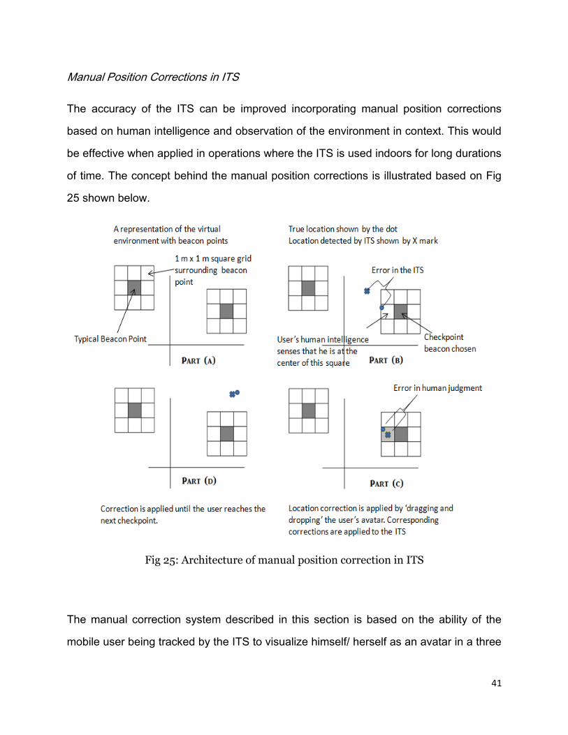
Manual Position Corrections in ITS
The accuracy of the ITS can be improved incorporating manual position corrections
based on human intelligence and observation of the environment in context. This would
be effective when applied in operations where the ITS is used indoors for long durations
of time. The concept behind the manual position corrections is illustrated based on Fig
25 shown below.
Fig 25: Architecture of manual position correction in ITS
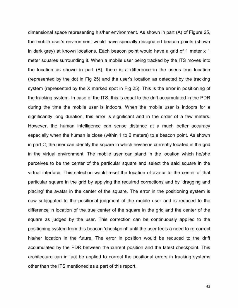
The manual correction system described in this section is based on the ability of the
mobile user being tracked by the ITS to visualize himself/ herself as an avatar in a three
42
dimensional space representing his/her environment. As shown in part (A) of Figure 25,
the mobile user’s environment would have specially designated beacon points (shown
in dark grey) at known locations. Each beacon point would have a grid of 1 meter x 1
meter squares surrounding it. When a mobile user being tracked by the ITS moves into
the location as shown in part (B), there is a difference in the user’s true location
(represented by the dot in Fig 25) and the user’s location as detected by the tracking
system (represented by the X marked spot in Fig 25). This is the error in positioning of
the tracking system. In case of the ITS, this is equal to the drift accumulated in the PDR
during the time the mobile user is indoors. When the mobile user is indoors for a
significantly long duration, this error is significant and in the order of a few meters.
However, the human intelligence can sense distance at a much better accuracy
especially when the human is close (within 1 to 2 meters) to a beacon point. As shown
in part C, the user can identify the square in which he/she is currently located in the grid
in the virtual environment. The mobile user can stand in the location which he/she
perceives to be the center of the particular square and select the said square in the
virtual interface. This selection would reset the location of avatar to the center of that
particular square in the grid by applying the required corrections and by ‘dragging and
placing’ the avatar in the center of the square. The error in the positioning system is
now subjugated to the positional judgment of the mobile user and is reduced to the
difference in location of the true center of the square in the grid and the center of the
square as judged by the user. This correction can be continuously applied to the
positioning system from this beacon ‘checkpoint’ until the user feels a need to re-correct
his/her location in the future. The error in position would be reduced to the drift
accumulated by the PDR between the current position and the latest checkpoint. This
architecture can in fact be applied to correct the positional errors in tracking systems
other than the ITS mentioned as a part of this report.

43
Accuracy Sensitive Intelligence in ITS
We are currently working on improving the ITS by incorporating accuracy sensitive
intelligence. The user is asked to make a prior judgment of the complexity of his/her
mission and the desired accuracy in location for the course of that particular mission.
We are incorporating features to measure the duration of time for which the mobile user
has been indoors and correlate them with the complexity of the task to estimate the
potential drift in the PDR. When this drift approaches the threshold limit (based on the
desired accuracy as defined by the mobile user), the system would send a reminder to
the user that he/she steps outdoors to recover the GPS and correct the drift
accumulated in the ITS and then continue on the mission.
The avenues described above are a good starting point to continue research in this field
and provide exciting outlets to improve the Integrated Tracking System in the near
future.
44
REFERENCES
Journal and Conference Papers
[1] Z. Aziz, C.J. Anumba, D. Ruikar, P.M. Carrillo, D.N. Bouchlaghem, Context aware
information delivery for on-site construction operations, in: Proceedings of the 22nd
CIB-W78 Conference on Information Technology in Construction, Institute for
Construction Informatics, Technische Universitat Dresden, Germany, CBI Publication
No: 304, 2005, pp. 321–32.
[2] J. Borenstein, L. Ojeda and S. Kwanmuang, Heuristic Reduction of Gyro Drift in a
Personal Dead-reckoning System, in: Journal of Navigation, Vol 62, No 1, January
2009, pp. 41-58.
[3] J. Burrell, K. Gay, Collectively defining context in a mobile, networked computing
environment, in: Proceedings of the Conference on Human Factors in Computing
Systems, Association for Computing Machinery (ACM), New York, NY, 2001, 231–232
[4] M. Hazas and A. Hopper, Broadband Ultrasonic Location Systems for Improved
Indoor Positioning, in: IEEE Transactions on Mobile Computing, Vol. 5, No. 5, May
2006, pp 536-547
[5] H.M. Khoury and V.R. Kamat, High-precision identification of contextual information
in location-aware engineering applications, in: Advanced Engineering Informatics 23,
2009, pp 483-496.
[6] H.M. Khoury and V.R. Kamat, Evaluation of position tracking technologies for user
localization in indoor construction environments, in: Automation in Construction, 18 (4),
2009, Elsevier Science, New York, NY, 444-457.
45
[7] R. Mautz, Indoor Positioning – An Ad Hoc Positioning System, in: Geodezija Ir
Kartografija / Geodesy and Cartography, 2008 34(2), pp 66-70.
[8] R. Mautz, Overview of Current Indoor Positioning Systems, in: Geodezija Ir
Kartografija / Geodesy and Cartography, 2009 35(1), pp 18-22.
[9] L. Ojeda and J. Borenstein, Non-GPS Navigation with the Personal Dead-reckoning
System, in: Proceedings of the SPIE Defense and Security Conference, Unmanned
Systems Technology IX, Orlando, Florida, April 9-13, 2007.
[10] L. Ojeda and J. Borenstein, Non-GPS Navigation for Security Personnel and
Emergency Responders, in: Journal of Navigation. Vol. 60 No. 3, September 2007, pp.
391-407.
[11] A. Pradhan, E. Ergen and B. Akinci, Technological Assessment of Radio Frequency
Identification Technology for Indoor Localization, in: Journal of Computing in Civil
Engineering, July/August 2009, pp. 230-238.
[12] B.N. Schilit, N. Adams, R. Want, Context-aware computing applications Workshop
on Mobile Computing Systems and Applications (WMCSA), Santa Cruz, CA, 1994, pp.
85–90.
Presentations
[13] T. Kohoutek, R. Mautz and A. Donaubauer, Real-Time Indoor Positioning using
Range Imaging Sensors, in: SPIE Photonics (Poster), Brussels, 15 April 2010