Integrated Power System - Newmar | DC Power | DC Power …€¦ · · 2016-01-11C) “External...
12
P.O. Box 1306, Newport Beach, California 92663 • Phone: 714-751-0488 • Fax: 714-957-1621 • E-Mail: techservice@newmarpower.com www.newmartelecom.com 1 Section Page Quick Reference Contents 2 I) Overview 3 II) Ac Power Quality Information 3 III) Installation 3 A) Materials B) Mounting C) Ac Input Wiring/Voltage Selection D) Output Wiring E) Initial Function/load Test IV) Internal Rectifier/Charger 5 A) Ac Input B) Dc Output Voltage C) Dc Output Current D) Internal Battery Breaker E) Over Voltage Protection Circuit F) Operating Temperature/forced Air Ventilation V) Status Indicators/monitors 6 A) “Ac Ok” Light B) “Internal Rectifier Status” Light C) “External Rectifier Status” Light D) “Battery Contactor Closed” Light E) “Check System” Light F) Digital Voltmeter/ammeter Section Page VI) Battery Back-up 7 A) Internal Batteries B) Internal Battery Replacement C) External Batteries D) A Note About Recharge Time E) Load Testing The Batteries VII) Alarm Contacts 8 A) Summary Alarm Function B) Summary Alarm Wiring C) Ac Input Fail Contacts (Option) D) External Rectifier Contacts (Option) VIII) Low Voltage Battery Disconnect 9 A) Circuit Purpose/function B) Actuation Voltage Adjustment C) Manual Battery Disconnect IX) External Rectifier And Redundant Ips 10 A) External Rectifier Installation B) Redundant Ips Installation X) Troubleshooting 11 XI) Specifications. 12 M-IPS As of 091814 Integrated Power System Models: IPS-48-11 & IPS-24-22 Installation / Operation Manual Contents
Transcript of Integrated Power System - Newmar | DC Power | DC Power …€¦ · · 2016-01-11C) “External...

P.O. Box 1306, Newport Beach, California 92663 • Phone: 714-751-0488 • Fax: 714-957-1621 • E-Mail: [email protected]
www.newmartelecom.com1
Section Page
Quick Reference Contents 2I) Overview 3II) Ac Power Quality Information 3III) Installation 3 A) Materials B) Mounting C) Ac Input Wiring/Voltage Selection D) Output Wiring E) Initial Function/load TestIV) Internal Rectifier/Charger 5 A) Ac Input B) Dc Output Voltage C) Dc Output Current D) Internal Battery Breaker E) Over Voltage Protection Circuit F) Operating Temperature/forced Air VentilationV) Status Indicators/monitors 6 A) “Ac Ok” Light B) “Internal Rectifier Status” Light C) “External Rectifier Status” Light D) “Battery Contactor Closed” Light E) “Check System” Light F) Digital Voltmeter/ammeter
Section Page
VI) Battery Back-up 7 A) Internal Batteries B) Internal Battery Replacement C) External Batteries D) A Note About Recharge Time E) Load Testing The BatteriesVII) Alarm Contacts 8 A) Summary Alarm Function B) Summary Alarm Wiring C) Ac Input Fail Contacts (Option) D) External Rectifier Contacts (Option)VIII) Low Voltage Battery Disconnect 9 A) Circuit Purpose/function B) Actuation Voltage Adjustment C) Manual Battery DisconnectIX) External Rectifier And Redundant Ips 10 A) External Rectifier Installation B) Redundant Ips InstallationX) Troubleshooting 11XI) Specifications. 12
M-IPS As of 091814
Integrated Power SystemModels: IPS-48-11 & IPS-24-22
Installation / Operation Manual
Contents

P.O. Box 1306, Newport Beach, California 92663 • Phone: 714-751-0488 • Fax: 714-957-1621 • E-Mail: [email protected]
www.newmartelecom.com2
Quick Reference Contents
Each of the main front or rear panel accessible features of the IPS is illustrated below, along with the page number where informa-tion on that particular feature is located.
Figure 1: IPS Front Panel
FIGURE 2: IPS Rear Panel
External Rectifier Input, Page 10
Summary Alarm Contacts, Page 8
External Rectifier Status Contacts, Page 9
Chassis Ground,Page 5
AC Input Fail Status Contacts (Option), Page 9
System Output, Page 5
External Batteries Input/Output, Page 8
AC Input Wiring and Voltage Selection, Page 5
AC Input Breaker, Page 5
Internal Battery Breaker, Page 6
Digital Voltmeter/Ammeter, Page 6
Rectifier Status Lights, Page 6
Output Voltage Adjust, Page 5
Check System Light, Page 6
Battery Contactor Closed Light, Page 6
Forced AirVentilation,Page 6
AC Input Status Light, Page 6
Auto Low Voltage and Manual Battery Disconnect, Page 9
Product RegistrationTo register your Newmar Integrated Power System, please visit us online at www.newmarpower.com/product_registration.html or for immediate response to your questions or comments, please call tech service @ 1-800-241-3897 or E-mail: [email protected].

P.O. Box 1306, Newport Beach, California 92663 • Phone: 714-751-0488 • Fax: 714-957-1621 • E-Mail: [email protected]
www.newmartelecom.com3
I) Overview
The Integrated Power System (IPS) is a precision-regulated power supply which incorporates built-in battery back-up, numerous power accessories and auxiliary power inputs within a single 2RU (3.5") chassis.
Following is a brief summary of the IPS main features. Each func-tion is fully detailed later in this manual.
• The precision regulated power supply simultaneously powers the system load and maintains back-up batteries at full voltage.
• Built-in batteries instantly power the load during AC failure—no switch-over delay. Plug-in terminals are provided for additional external batteries to increase reserve power capacity.
• Plug-in terminals are provided for easy paralleling of an exter-nal rectifier for increased current. These instructions also explain optional connection of an additional IPS for 100% redundancy of all IPS features.
• An automatic low voltage battery disconnect (LVBD) protects batteries and load during extended power outages. Manual bat-tery disconnects are also provided.
• Front panel monitoring features include a combination digital ammeter/voltmeter and system status indicator lights.
• Form C Summary failure contacts enable remote alarm/indica-tion under any of the following conditions: loss of internal rectifier output; loss of external rectifier output; battery contactor open. AC Input failure alarm contacts are also available as a factory-installed option.
• Protection features include the following: AC input breaker, inter-nal battery breaker, automatic thermal shutdown and recovery, current-limiting, short-circuit and over-voltage protection.
II) AC Power Quality And EMI Compatibility Some Pre-Installation Considerations
A) AC Power Quality
When designing an AC-DC power system for communication sites, reliability is of prime concern. One factor which can seriously impede system reliability is poor AC input power quality. Transient disturbances on the power lines can severely weaken or cause fail-ure of semiconductors in power supplies and communication gear. It is important that you know the input power quality when install-ing the IPS. Following is some basic information on the subject:
Causes
Transients are characterized as a voltage pulse of high energy and very short duration impressed upon the AC wave form. These over voltage pulses can range from 1 to 100 times the normal AC volt-age level and can last for a fraction of a cycle to a few cyclesTransient disturbances can be placed into two categories:
• Lightning generated
• Equipment generated
A direct lightning hit on a utility power line will cause a high energy voltage transient to travel in both directions along the power line. This distur-bance can impact equipment hundreds of miles from the strike point.
Equipment generated transient sources include utility fault condi-tions and load switching as well as on-site equipment such as pumps and air conditioning loads, motors, phase control equip-ment.
Recommendations
If the power source quality is suspect or unknown, it is recommend-ed that an AC power quality survey be conducted by a power quality consultant or power conditioning firm. Corrective measures may include lightning suppressors, line conditioners and filters.
An AC transient suppressor is recommended for installations in third world countries and sites that are subject to nearby lightning strikes or transients caused by nearby motor contactors, air condi-tioning compressors, etc.
B) EMI (Electro-Magnetic Interference) Considerations
The IPS employs switch-mode technology to convert AC to DC. It is designed to produce minimal EMI levels when in operation, some extremely sensitive installations may not even tolerate what little EMI is produced.
Analog microwave and other sensitive radio sites may require additional input/output filtering and careful installation. In some cases linear power supplies (also available from NEWMAR) should be considered, as they emit lower EMI (although they are more susceptible to “brown-outs” or voltage sags and high input volt-age).
C) Other Factors
Some of the numerous factors which must be considered when designing communication systems subject to electrical interference include:
- RF Signal strength - Ground loops - Power and signal cable routing proximity - Power supply and radio mounting locations - Antenna, signal, and power grounds
Please contact the factory if it is suspected that any of these factors may affect the installation.
III) Installation
Note: This section covers only mounting, input and output wiring. Other aspects of installation, such as alarm contact and parallel rectifier wiring, are optional and are covered in those sections which pertain to that particular function.
Caution: During the installation ensure that the Internal Battery Breaker remains in the OFF position. The EXTERNAL BATTERY ter-minals on the rear of the IPS are “HOT” whenever that breaker is in the ON position.
A) Materials
Check to see that each of the following items have been included with the installation kit that is packaged with the IPS. For any miss-ing items please contact the factory.

P.O. Box 1306, Newport Beach, California 92663 • Phone: 714-751-0488 • Fax: 714-957-1621 • E-Mail: [email protected]
www.newmartelecom.com4
(1 ea.) 6' IEC Power Cord(1 ea.) CA-24 Anderson Connector Assembly, with Wires(1 ea.) CK-50 Anderson Connector Kit, with Housing and two Pins(1 ea.) Molex 6 Wire "Pigtail" Connector(6 ea.) Black Oxide Screws, 6-32 x 5/16"(6 ea.) # 6 Stainless Steel Splitlock Washers(6 ea.) Stainless Steel Screws, 8-32 x 5/16"(6 ea.) # 8 Stainless Steel Splitlock Washers(2 ea.) Mounting Brackets for 19" Rack, Fixed (Stamped 13917 D)(2 ea.) Mounting Brackets for 19" Rack, Adjustable (Stamped 13917-1)(2 ea.) Mounting Brackets for 23" Rack, Fixed (Stamped 13918 C)(2 ea.) Mounting Brackets for 23" Rack, Adjustable (Stamped 13918-1)
B) Mounting
The IPS has been designed for two different mounting options; 1) 19" and 23" relay rack mount or, 2) “Universal” table-top, wall or under-shelf mount. Hardware for relay rack mounting is included with the IPS. (Contact the factory if the universal mounting option is required.) The internal batteries are a sealed type and are tightly secured within the unit, so mounting with any orientation is acceptable.
1) Relay Rack Mount: The IPS is provided with two sets of four mounting brackets suitable for relay racks with 3" EIA channel/rails; one set is for 19" racks, the other for 23" racks. Each set consists of two "fixed" and two adjustable brackets.
The fixed brackets have round chassis attachment holes and accommodate three each 6-32 x 5/16" pan head phillips screws (provided). Attach these first in the front position as shown in FIGURE 3 on the following page, then mount the IPS onto the rack on the front side of the rail.
The adjustable brackets have slotted chassis attachment holes and accommodate three each 8-32 x 5/16" pan head phillips screws (provided). Attach them loosely to the IPS chassis in the rear position as shown in FIGURE 3, then secure the brackets to the rear of the rail. Finally, tighten the chassis attachment screws. The holes on the brackets are slotted to adjust for racks with slightly differing front-to-rear rail dimensions.
Note: This dual bracket installation is for 6" forward mounting only. Flush mounting is typically used in a cabinet installation. Due to the weight of the IPS, 6" forward mounting is the only recommended configuration for relay rack installations.
FIGURE 3: Relay Rack Mounting Bracket Installation
2) "Universal" Mounting Option (Table-top, Wall or Under-shelf) : Two 14" long universal brackets are available from the factory which may be attached to the sides to secure the unit above or below a horizontal surface or to a vertical surface, as required (see FIGURES 4A, 4B, 4C below and on the following page). Tapped bracket attachment holes in the side of the chassis allow for installation of the brackets oriented toward either the top or bottom of the unit. To order these, contact the factory and request model UMB-PM.
Attach the brackets using the twelve 8-32 x 1/4" pan-head phillips machine screws provided. Install three rubber grommets (provided) in each mounting bracket. WD-40 or a similar lubricant will ease installation of the grommets.
Secure the IPS to the mounting surface with six 1/4" screws or lag bolts (not provided).
FIGURES 4A, 4B, 4C: Universal Mounting Options
Note: The DC. output of the IPS is completelyisolated from its case, therefore mounting to eithermetal or non-metal surfaces is acceptable.
3) Other Mounting Options: If other mounting options, such as cabinet mounting, are required, please con-tact the factory.
Install "adjustable" brackets at rear position using provided stainless steel 8-32 x 5/16" screws and # 8 lock washers.
Install "fixed" brackets at front position using provided black oxide 6-32 x 5/16" screws and # 6 lock washers.
4A: Table-top Mount
4B:Under-Shelf Mount
4C: Wall Mount

P.O. Box 1306, Newport Beach, California 92663 • Phone: 714-751-0488 • Fax: 714-957-1621 • E-Mail: [email protected]
www.newmartelecom.com5
C) AC Input Wiring and Voltage Selection
1) Input Wiring: The IPS is provided with an IEC power cord (in the installation kit) with a NEMA 5-15 plug for a 115 VAC outlet on one end and a molded socket at the other which fits the entry module at the rear of the unit. If the 5-15 plug is not suited to the available AC outlet, 1) obtain an IEC cord with appropriate plug or 2) cut off the 5-15 plug, obtain the correct plug for the outlet and attach it to the provided IEC cord. When replacing the plug, pay careful attention to the pin wiring as follows:
Brown................................AC Hot (over-current protected)Blue...................................AC NeutralGreen*................................AC Ground (safety, earth)* may be Green with Yellow Stripe
Caution: (230 VAC applications only): If AC input is derived from a source consisting of two HOT leads (phase-to-phase 230 VAC input voltage), an external fuse or circuit breaker must be used to protect the unfused (formerly NEUTRAL, now HOT) lead.
2) Input Voltage Selection: As shipped from the factory, the IPS is set up for 115 VAC input. For 230 VAC applications use a small screwdriver to slide the recessed 115/230 input select switch located on the left hand side of the unit into the 230V position. Positions are identified on the switch.
Caution: Applying 230 VAC input to the IPS when the input selector switch is in the 115V position will severely damage the unit. Conversely, if the input voltage selector is set in the 230V position while 115 VAC is being applied, damage will not occur, but the “AC OK” and “INTERNAL RECTIFIER STATUS OK” lights will illuminate, giving a false indication of proper operation. Ensure the input selector is in the proper position before applying AC.
D) Output Wiring
1) A 24" dual wire assembly terminated with 1/4" ring lugs and a keyed modular power connector (labeled CA-24 in the installation kit) is provided for wiring DC output to the load. Attach the lugs to the load or distribution bus, then insert the connector at the position labeled “SYSTEM OUTPUT” on the rear panel of the IPS.
IMPORTANT NOTE: Model IPS-48-11 is designed only for use in positive ground systems. Model IPS-24-22 is designed for use only in negative ground systems. Over-current protection and the internal battery contactor are installed in the "Hot" side of the IPS output.
The IPS chassis is floating in relation to the DC output ground/return. To supplement the earth grounding of the AC input cord, the installer may use the grounding stud on the rear panel to ground the IPS chassis to the system ground/return.
2) If the wires on the provided connector assembly are not long enough to reach the load or distribution bus, use the provided spare connector housing and contact pins to construct an assembly of suitable length. The housing and pins accommodate # 8 cable, which is a sufficient gauge for all IPS installations. The pins must be crimped, not soldered.
3) Beside the system output connector on the rear panel are connectors for attaching optional external batteries and external rectifier(s). These installations are covered elsewhere in this manual. See section VI-C for information on wiring external batteries. See section IX-A for information on external rectifier installations.
E) Initial Load/Function Test
When the installation is complete, put the IPS into operation by switching on the AC Input breaker. IMPORTANT: Ensure that the Battery Disconnect selector is in the AUTO LOW VOLTAGE position and that the Internal Battery Breaker is in the ON position. Otherwise, no battery charging will take place and the batteries will not be connected to provide continued operation of the load in the event of AC failure.
Prior to departing the installation site, a few initial load/function tests are recommended. Proceed as follows:
1) Check for proper operation of the radio (or other load) at maximum current draw (i.e., while in transmit) without the batteries on-line. If only internal batteries are used, they can be taken off-line by switching the Internal Battery Breaker to the OFF position. If external batteries are used the Battery Disconnect selector on the front panel must be switched to MANUAL DISCONNECT to take them off-line. This switch disconnects both internal and external batteries.
2) Check for proper operation of the load during AC interruption. To do this, return the Battery Disconnect selector to the AUTO LOW VOLTAGE position and return the Internal Battery Breaker to the ON position. Then shut off the AC Input breaker. Observe that the internal and/or external batteries enable continued operation under the same maximum load conditions as described above.
3) An initial battery load test is also recommended. The readings from this test can be used in future site equipment checks to determine the relative “health” of the internal and/or external batteries. For the battery load test procedure refer to section VI-E.
IV) Internal Rectifier/Charger
A) AC Input
1) The IPS will operate on either 115V or 230V nominal input at 50-60 Hz (See Specifications section for actual input ranges.) Input voltage selection is explained in section II.
2) AC input is protected against over-current and internal short circuit conditions by the circuit breaker/input power switch on the front panel. The “AC ON” indicator light beside the switch will illuminate when it is in the ON position and AC is being applied.
B) Output Voltage
1) The IPS-48-11 produces 48 VDC nominal. Model IPS-24-22 produces 24 VDC nominal. Ground reference is an important consideration. Refer to section III-D for a discussion of this issue as it relates to the output of the IPS.
2) Factory-set output voltage and approximate user-adjustment range are specified below. Adjustment is made at a front-panel potentiometer (located beside the voltmeter/ammeter) using a small flat tip screwdriver.
Output Voltage Adjustment Range Factory SetModel Output Voltage Adjustment RangeIPS-48-11 54.4 VDC 42.0-56.0 VDCIPS-24-22 27.2 VDC 20.0-28.5 VDCCaution: The factory set voltages are proper charging voltages for the supplied internal batteries. Consult with the battery manufacturer
for proper charging voltages when using batteries other than those supplied by NEWMAR. Over or undercharging will result in battery damage or shortened life. Use an accurate digital multimeter when setting float voltage. The IPS voltmeter provides approximate voltage only.

P.O. Box 1306, Newport Beach, California 92663 • Phone: 714-751-0488 • Fax: 714-957-1621 • E-Mail: [email protected]
www.newmartelecom.com6
C) Output Current
1) The IPS is rated for continuous duty at the current level indicated by model number (i.e., IPS-48-11 is rated at 11 amps continuous; The IPS-24-22 is rated at 22 amps continuous).
2) To prevent overload when recharging severely discharged batteries, output current of the internal rectifier is limited at approximately 105 % of the continuous duty rating by a current fold-back circuit.
3) The maximum total output capacity, including systems with an external rectifier and batteries is 40 amps. The maximum current draw of the load must not exceed this rating. In addition, any external battery bank must be sized so that, upon restoration of AC after extended power outage, the current draw from the batteries does not exceed 40 amps. Refer to section VI-C for a complete discussion of external battery bank installations.
D) Internal Battery Breaker
To prevent damage to wiring in the event of high current output from the internal batteries (typically associated with a short circuit), protection is provided by a circuit breaker on the front panel (labeled “INTERNAL BATTERY BREAKER”). For charging of the internal batteries to take place during normal operation this breaker must be placed in the ON position. Note: This circuit breaker will not protect against over-current conditions from any external batteries wired to the IPS. External batteries must be routed through a separate fuse or circuit breaker.
E) Over Voltage Protection (OVP) Circuit
To protect the load against damaging high voltage due to a failure of the rectifier's voltage regulation circuitry, the IPS is equipped with a fast-acting Over Voltage Protection (OVP) circuit which immediately shuts down the IPS rectifier output. Random disturbances on the AC input power line may also cause activation of this circuit. A possible indication that this circuit has tripped is if the AC OK green light is illuminated but there is no rectifier output. If it is suspected that the OVP circuit has been activated, switch off the AC Input breaker for several seconds then switch it back on. Normal output should resume if the shutdown was due to random AC line disturbance. If the same symptom recurs and all other causes have been ruled out, the unit must be returned for repair.
F) Operating Temperature/Forced Air Ventilation
Optimal operating temperature range is maintained by forced air ventilation provided by an integral cooling fan. This fan is in continuous operation whenever AC is applied.
The IPS is protected against overheating by an automatically resetting thermal shutdown circuit. If thermal cycling is noted check to see that the fan goes back into operation after the unit has cooled and AC is applied. If it does not, the unit must be returned to the factory for repair. The fan is not user-serviceable.
V) Status Indicators/monitors
Numerous front panel indicators/monitors provide status of the internal and external rectifiers, battery contactor and low voltage battery disconnect. The function of each of these indicator/ monitors is explained here. Green lights indicate nominal or normal conditions; red indicates a possible system problem.
(Note: An entire section of this manual is devoted to the operation of the LVBD and those indicators which apply to that function only will be covered in that section)
A) “AC OK” - Green Light
When this light is illuminated, it indicates simply that AC voltage is being applied to the internal rectifier. If this indicator is not illuminated, check your AC source and check to see that the AC Input circuit breaker is in the ON position.
B) “INTERNAL RECTIFIER STATUS” - Green Light
This light indicates that the internal rectifier is functioning properly and producing nominal output voltage. Note: Even if this indicator is extinguished the “SYSTEM OUTPUT” terminals may still be “hot”, either from the internal or external batteries or from the external (parallel) rectifier.
C) “EXTERNAL RECTIFIER STATUS” - Green Light
This light is illuminated only when there is an external rectifier connected to the IPS and is functioning properly, as signaled by activation of the external rectifier’s form C contacts. Note: Any external rectifier used with the IPS must employ Form C contacts for this indicator to function. These contacts are provided standard with NEWMAR PM Series Power Modules and the IPS.
D) “BATTERY CONTACTOR CLOSED” - Green Light
This light is illuminated whenever the internal battery contactor is closed. It does not necessarily indicate that the internal batteries are connected to the SYSTEM OUTPUT terminals or are being charged by the internal rectifier. The internal battery breaker on the front panel must also be in the ON position to complete this connection.
Note: If external batteries are connected to the IPS they are continuously connected to the SYSTEM OUTPUT terminals when the battery contactor is closed, even if the internal battery breaker is in the OFF position.
For more information on the function of the battery contactor and low voltage battery disconnect circuit refer to section VIII.
E) “CHECK SYSTEM” - Red Light
This light illuminates during any of the following four conditions:
1) Any condition which causes a loss of internal rectifier output, including failure of the rectifier module itself or from loss of AC input to the rectifier.
2) Any condition which causes loss of external rectifier input (assuming that an external rectifier has been installed and uses compatible Form C status contacts.)
3) Whenever the battery is disconnected by the Auto Low Voltage Battery Disconnect.
4) Whenever the Battery Disconnect switch is put into the Manual Disconnect position while the internal or external rectifier is operating.
F) Digital Voltmeter/Ammeter
1) The digital meter on the front panel of the IPS may be used to monitor either system voltage (to the nearest 1/10 volt) or total rectifier (internal and/or external) output current (to the nearest
amp). Meter accuracy is 1.6% ± one digit. Note: The meter does not indicate current coming from the battery.
P.O. Box 1306, Newport Beach, California 92663 • Phone: 714-751-0488 • Fax: 714-957-1621 • E-Mail: [email protected]
www.newmartelecom.com7
2) To switch between voltage and current indication simply depress and release the Meter Select switch. A diagram beside the switch indicates the volts/amps switch positions. Note: Because model IPS-48-11 is designed for positive ground applications a minus symbol (-) will appear in the meter display for both volts and amps with that model.
3) If a parallel rectifier is connected to the IPS through EXTERNAL RECTIFIER port, the ammeter will indicate the combined current output of both units.
VI) Battery Back-up
A) Internal Batteries
1) The IPS is supplied with a built-in back-up battery bank consisting of four sealed lead-acid 12 volt, 5.0 amp-hour batteries.
The wiring configuration and internal reserve capacity depends on model as follows:
Model Wiring Configuration Reserve CapacityIPS-48-11 Series 5 Amp-HoursIPS-24-22 Series/Parallel 10 Amp-Hours
The chart below outlines some typical battery back-up run times as they relate to constant current draw:
Internal Battery Capacity Chart
Constant Current Performance (Amps) to 1.75 VPC @ 25° CModel 5 MIN. 15 MIN. 30 MIN. 1 HR. 2 HRS. 4 HRS. 8 HRSIPS-48-11 15 8.0 5.0 3.0 2.0 1.2 .7IPS-24-22 30 16.0 10.0 6.0 4.0 2.4 1.4
Note: For information regarding periodic checks of the relative “health” of the back-up battery system, refer to Section VI-E, following.
2) The output of the power supply is “floated” across the battery bank to maintain it at full voltage. Unless the batteries are manually disconnected (or the LVBD disconnects batteries), they are always on-line to the load.
3) To prevent dangerous over-current draw from the internal batteries in the event of a short circuit, reverse polarity external battery connection or severe overload, the output from the internal batteries is protected by the Internal Battery Breaker located on the front panel.
B) Internal Battery Replacement
Replacement batteries are available from NEWMAR. Contact the factory and specify part number 591-0412-0, 12 volt 5.0 A-H battery. If you use batteries obtained from another source, ensure that they are of the same type, rating and approximate age. All batteries should be replaced at the same time.
Caution: Take care not to short the battery terminals during removal and installation. The resulting high current will damage the batteries.
A blank section for logging technician's notes has been provided at the end of this manual, section XII. It is recommended that a record be made there of this service performed upon completion. Proceed with battery replacement as follows:
1) Disconnect the AC input power cord.
2) If external batteries are used, disconnect them from the IPS.
3) Loosen but do not remove the three black # 6 phillips head screws on the top rear of the unit which secure the cover. Remove the cover.
4) Using a 3/8" nut driver, remove the four nuts which secure the two battery hold-down brackets to the base of the unit.
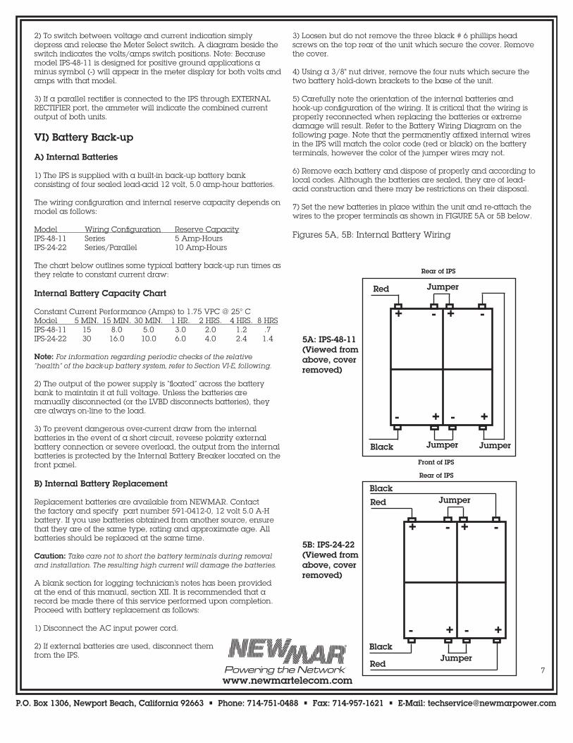
5) Carefully note the orientation of the internal batteries and hook-up configuration of the wiring. It is critical that the wiring is properly reconnected when replacing the batteries or extreme damage will result. Refer to the Battery Wiring Diagram on the following page. Note that the permanently affixed internal wires in the IPS will match the color code (red or black) on the battery terminals, however the color of the jumper wires may not.
6) Remove each battery and dispose of properly and according to local codes. Although the batteries are sealed, they are of lead-acid construction and there may be restrictions on their disposal.
7) Set the new batteries in place within the unit and re-attach the wires to the proper terminals as shown in FIGURE 5A or 5B below.
Figures 5A, 5B: Internal Battery Wiring
+ - + -
- + - +
Red Jumper
Black Jumper Jumper
Rear of IPS
Front of IPS
+ - + -
- + - +
Red
Jumper
Rear of IPS
Black
Black
Red
5A: IPS-48-11(Viewed from above, cover removed)
5B: IPS-24-22(Viewed from above, cover removed)
Jumper

P.O. Box 1306, Newport Beach, California 92663 • Phone: 714-751-0488 • Fax: 714-957-1621 • E-Mail: [email protected]
www.newmartelecom.com8
8) Re-install the hold-down brackets and replace the cover. Reconnect external batteries (if necessary), then restore AC power to the IPS.
Note: If batteries are removed from the unit for storage, make sure they have been fully charged first. Storing batteries in a discharged condition will greatly shorten their life.
C) External Batteries
Caution: Over-current protection for any external batteries must be provided by the installer.
To provide for optional increased operation time on battery back-up the IPS comes equipped with a connector on the rear panel for the attachment of an external battery bank. An unassembled keyed modular power plug is provided to terminate the battery wiring and mate with the rear panel connector. Insertion-lock connector pins are provided with the plug housing. These will accommodate # 8 AWG wire. (If the spare connector housing and pins have been used for any other aspect of the installation, additional spares are available from the factory. Request model CA-50.)
When external batteries are connected to the EXTERNAL BATTERY terminals, and the internal batteries have not been removed, they are in parallel and therefore these must be of the same type, rating and approximate age. The maximum recommended capacity when wiring this way depends upon model as listed in the chart below:
Model Maximum Battery Capacity Internal Total (Combined Internal and External)IPS-48-11 5 A-H 200 A-HIPS-24-22 10 A-H 400 A-H
Rackmount battery modules from NEWMAR match the internal battery type and rating and are suitable for plug-and-play back-up battery installations. They are available in 48 volt, 5 amp-hour and 24 volt, 10 amp-hour ratings. For complete information, visit the NEWMAR web site, www.newmartelecom.com and click on Battery Modules, Battery Shelves.
If the installer chooses to use a different type of external back-up battery string, it is recommended that the internal batteries be removed. Then the installer may then attach as many batteries to the EXTERNAL BATTERY terminals as required up to the maximum capacities specified above. Battery shelves are available from NEWMAR for this purpose. Contact the factory for more information on battery shelves and larger battery installations.
D) A Note About Recharge Time
The back-up batteries and the load share the rectifier output whenever the IPS is operating. Therefore, the size of the load will have a direct effect upon the amount of time it takes to recharge batteries after an AC power outage. The greater the load, the longer the recharge time. When the equipment load is equal to the maximum output of the IPS no battery charging is taking place.
E) Load Testing the Batteries
All batteries are subject to a certain loss of capacity over time. The rate of capacity loss will depend on a number of factors such as age, ambient temperature and number of charge/discharge cycles. Therefore, in order to guarantee that the batteries will provide the required back-up in an emergency loss of AC power, it
is recommended that they be periodically load tested to verify sufficient back-up capacity. This test will also serve the valuable function of “exercising “ the batteries, which contributes to longer life.
The first load test should be performed as soon as possible after installation. The results should be recorded for future reference as a benchmark for comparison to all future test results. The batteries must begin fully charged for the test to be accurate. If unsure about the relative state of the batteries, allow the IPS to run for 24 hours with no load and the Internal Battery Breaker in the ON position.
A reliably consistent load is required for this test. The maximum current of the test load must not exceed the 15 minute constant current performance rating of the Battery Capacity Chart in section VI-A. Prior to load testing the batteries, ensure the IPS is on and operating normally, that the Battery Disconnect selector is in the AUTO LOW VOLTAGE position and that the Internal Battery Breaker is in the ON position, then proceed as follows:
1) Connect the constant current load to the SYSTEM OUTPUT terminals using the provided Connector Assembly but leave the load turned off, initially.
2) Check to see that the digital meter on the front panel of the IPS is in the voltage measurement position. (Note: The front panel ammeter cannot be used to check amperage to your load from the batteries—the ammeter displays output current from the internal and/or external rectifiers only.) Turn the AC Input breaker to the OFF position.
3A) If this is the first load test of the batteries, turn on the load and then record the reading of the digital voltmeter after 5 minutes, 10 minutes and 15 minutes. These are the benchmark voltages you should use for future tests.
3B) If this is a subsequent test, turn on the load and record the amount of time it takes for the batteries to reach the benchmark voltages recorded in step 3a. When the batteries are under the identical constant current load as in the initial test and nonetheless fall to the benchmark voltages 20 % faster (i.e., at 4, 8 or 12 minutes) they should be replaced. If replacement is indicated, see section VI-B for procedure.Note: Batteries which are 5 years or older should be replaced regardless of apparent capacity to ensure reliable performance in an emergency power loss.
VII) Alarm Contacts
A) Summary Alarm Function
The IPS is equipped with a set of Form C contacts for use of an optional remote summary alarm. These contacts are activated under all of the same conditions which result in illumination of the “CHECK SYSTEM” light on the front panel. These are:
1) Any condition which causes a loss of internal rectifier output, including failure of the rectifier module itself or from loss of AC input to the rectifier.
2) Any condition which causes loss of external rectifier input (assuming that an external rectifier has been installed and uses compatible Form C status contacts.)
3) Whenever the battery is disconnected by the Auto Low Voltage Battery Disconnect.

P.O. Box 1306, Newport Beach, California 92663 • Phone: 714-751-0488 • Fax: 714-957-1621 • E-Mail: [email protected]
www.newmartelecom.com9
4) Whenever the Battery Disconnect switch is put into the Manual Disconnect position while the internal or external rectifier is operating.
B) Summary Alarm Wiring
A color-coded wire “pigtail” with keyed plug is provided for wiring convenience and to facilitate proper connections. The plug holds six wires. Three are used for the summary alarm contacts. The other three are used for connection to the status contacts of the parallel rectifier (if one has been installed).
The alarm may be wired with the relay “normally open” or “normally closed”, as needed. The contact configuration is illustrated beside the connector on the rear panel and the position of the contacts during failure and normal operating condition is illustrated below:
Figure 6: “FAIL” And “OK” Relay Contact Positions
C) AC Input Fail Contacts - Optional
For installations that require remote indication/alarm of loss of AC input to the IPS, Form C AC Input Failure contacts are available as a factory-installed option. The IPS is normally shipped with an empty connector occupying the AC Fail connector port. If this option has been installed, the connector will have a set of three pins in the left side of the connector, a label which identifies the voltage of the alarm (115 or 230 VAC), and a second failure contact wiring harness will be provided in the installation kit for wiring the alarm.
Installation is identical to the Summary Alarm wiring described previously.
D) External Rectifier Status Contacts
Refer to section IX-A for all aspects of external rectifier installation.
VIII) Low Voltage Battery Disconnect (LVBD)
A) Circuit Purpose/Function
An automatic LVBD circuit in the IPS prevents battery system and/or communication equipment damage due to excessive battery discharge (typically encountered during an extended loss of AC power to the site) by automatically disconnecting the battery at a designated preset voltage and reconnecting the battery at another preset voltage. The disconnect and connect voltage actuation points are user-adjustable (as described below). An internal battery contactor opens and closes the circuit to the battery.
Note: Under most circumstances the LVBD will reconnect the battery immediately following restoration of AC power to the system.
B) Actuation Voltage Adjustment
Caution: This procedure requires raising and lowering the output voltage of the IPS beyond the point where critical loads may be affected or damaged. Any load of this type should be disconnected before proceeding with this adjustment.The factory set actuation voltages are as follows:
Model IPS-48-11 IPS-24-22Disconnect (OPEN) 42.0 VDC* 21.0 VDC*Connect (CLOSE) 49.0 VDC* 24.5 VDC* * ±200mVThe connect and disconnect voltages may be adjusted ± 15%.
Access to the contactor actuation voltage potentiometers is through the front panel ports labeled “OPEN” and “CLOSE”. Adjustment may be made using a small flat tip screwdriver.
Do not set the connect and disconnect voltages too close together. Rapid cycling of the LVBD may result.
Use the following procedure to adjust the actuation voltages:
1) Place the Internal Battery Breaker in the OFF position. Disconnect any external batteries attached to the IPS.
2) Place the Battery Disconnect switch in the “AUTO LOW VOLTAGE” position.
3) Set the meter select switch on the front panel to the DC VOLTAGE position.
4) Turn the “CLOSE” potentiometer fully clockwise. Turn the “OPEN” potentiometer fully counterclockwise.
5) The disconnect (open) voltage must be set first. Using the Voltage Adjust pot on the front panel adjust the IPS output voltage until the desired disconnect voltage is indicated by the meter. Slowly turn the “OPEN” potentiometer clockwise until the red “BATTERY DISCONNECTED” light illuminates and the green “BATTERY CONTACTOR CLOSED” indicator goes out. (At the same time you should hear an audible click of the LVBD contactor opening.)
6) Verify the correct disconnect voltage by turning the variable power supply up until the contactor closes, then slowly lowering supply voltage until the contactor opens. If necessary, slightly adjust the potentiometer up or down, then reverify disconnect voltage. Repeat this process until the desired disconnect voltage is achieved.
7) Set the connect (close) voltage. Adjust the IPS output voltage until the desired connect voltage is indicated by the meter. Note that the “BATTERY DISCONNECTED” light is still illuminated. Slowly turn the “CLOSE” potentiometer counterclockwise until the green “BATTERY CONTACTOR CLOSED” indicator on the front panel il-luminates and the “BATTERY DISCONNECTED” light goes off. (At the same time you should hear an audible click of the LVBD contactor closing.)
8) Verify the correct connect voltage by turning the IPS output volt-age down until the contactor opens, then slowly raise the voltage until the contactor closes. If necessary, slightly adjust the poten-tiometer up or down, then reverify connect voltage. Repeat this process until the desired connect voltage is achieved.
9) Return the IPS to normal battery float voltage.
Positions used with external rectifier only
FAIL OKPositions used with external rectifier only

P.O. Box 1306, Newport Beach, California 92663 • Phone: 714-751-0488 • Fax: 714-957-1621 • E-Mail: [email protected]
www.newmartelecom.com10
C) Manual Battery Disconnect
Whenever the Battery Disconnect is in the Manual Disconnect posi-tion all internal and external batteries are completely disconnect-ed from the rectifier(s) and SYSTEM OUTPUT terminals, regardless of battery voltage or whether the rectifier(s) are operating. This differs from the Internal Battery Breaker which, when in the OFF position, disconnects only the internal batteries.
IX) External Rectifier And Redundant IPS Installations
The IPS may be supplemented with an external rectifier (NEWMAR Power Module) in order to provide increased current capacity. Alternatively, redundancy of virtually all IPS features can be achieved using a second IPS. The installation for each configuration differs somewhat, as follows:
A) External Rectifier (NEWMAR Power Module) Installation
1) This configuration is recommended when increased output current is required to meet load demands, but there is no need for duplication of all IPS features. NEWMAR's PM Series Power Modules are recommended for use as external rectifiers due to the compatibility of circuits, available voltages/amperages and features such as Form C status contacts. (For complete information on PM Series Power Modules, visit our web site: www.newmartelecom.com)
The maximum external rectifier amperage which may be wired to the IPS-48-11 using the EXTERNAL RECTIFIER terminal is 30 amps. The maximum for model IPS-24-22 is 20 amps. Combine models to achieve the required system current. Some examples:IPS-48-11 + PM-48-10 = 48 volt, 21 amp systemIPS-48-11 + PM-48-18 = 48 volt, 29 amp systemIPS-48-11 + PM-48-10 x 2 = 48 volt, 31 amp systemIPS-48-11 + PM-48-10 x 3 = 48 volt, 41 amp systemIPS-24-22 + PM-24-20 = 24 volt, 42 amp systemWhen wiring more than one external rectifier to the IPS it is recommended that the outputs of the multiple units be bussed to a separate external terminal strip, and the strip wired to the EXTERNAL RECTIFIER terminal.
Important: When adding external rectifier(s) to allow model IPS-48-11 to supply a 20 amp or greater load, installation of external batteries is required. The Internal Battery Breaker is rated at 20 amps. In the event of loss of rectifier output the breaker will trip unless some of the load current is shared by external batteries (and/or the LVBD circuit will disconnect the battery due to the extreme overload on the limited back-up capacity.)
2) Connecting the power input from an external rectifier (PM) requires a connector assembly identical to the one provided for the IPS-to-load connection. Contact the factory and request model CA-24. The wires on this assembly are terminated with 1/4" ring lugs at one end which are attached to the PM output terminals, and a modular power plug at the other end which mates with and is inserted into the connector labeled “EXTERNAL RECTIFIER” on the rear of the IPS.
3) The Power Module is provided with a status contact wiring pigtail with six wires. The blue, green and yellow wires are unused in this installation and may be clipped or tied off. Splice the remaining wires to the IPS status contact wires coming from the connector position labeled EXTERNAL RECTIFIER INPUT on the rear panel.
Use 18 AWG parallel connectors, splice the wires together according to the following color code:
PM Status Wire Connects To IPS Status WireBrown BlueRed GreenOrange Yellow
4) To complete the installation turn the Power Module off and on while the IPS is in operation to verify proper operation, as indicated by the IPS front panel status lights. When the PM is shut off, the “EXTERNAL RECTIFIER ON/OK” light should be extinguished and the “CHECK SYSTEM” light should be illuminated. When the PM is turned on the opposite should occur.
B) Redundant IPS Installation
A second IPS may be wired into the system with the first to provide virtually 100% redundancy of all IPS functions and features. Observe the following guidelines in wiring such a system:
1) Wiring for both units should be made in parallel directly to the load or distribution bus. Do not use the EXTERNAL RECTIFIER connection, as shutdown of both units may be required to replace a single failed unit, thus negating a primary reason for redundancy.
2) As in all parallel installations, proper load sharing must be facilitated by ensuring that all power wiring is of the same length and gauge. In addition, the output current of each unit should be individually adjusted to match (using the front panel Voltage Adjust pot) when under a load of approximately 50 % of IPS current rating.
3) Separate summary alarms may be wired for each IPS. If a single summary alarm for the redundant system as a whole is desired, wire the summary alarm pigtails as follows:
For alarm in a "Normally Open" (N.O.) configuration: Wire the N.O. and Common contacts of each IPS in parallel by connecting the wires brown-to-brown and red-to-red (orange wires are unused).
For alarm in a "Normally Closed" (N.C.) configuration: Wire the N.C. and Common contacts of each IPS in series by connecting the brown wire of IPS # 1 to the orange wire of IPS # 2, then connecting the alarm across the orange wire of IPS # 1 and the brown wire of IPS #2.
When both units are wired together as explained above any condition causing loss of output from either or both units will result in activation of a single remote alarm.
4) A separate fused external battery bank may be connected for each unit or a single bank may be wired in parallel to both units. However, the installer must be aware that using only one battery bank will create a possible single point of failure (the shared battery bank/battery fuse). Also, the capacity of a shared external battery bank must not exceed the limits of a single IPS as explained in section VI-C.

P.O. Box 1306, Newport Beach, California 92663 • Phone: 714-751-0488 • Fax: 714-957-1621 • E-Mail: [email protected]
www.newmartelecom.com11
X) TroubleshootingProblem Possible Cause Solution
Refer to LVBD adjustment procedure
Same as above
Same as above
Reduce load to within IPS current rating or check for short on output
Place AC input select switch in the 230V position
Turn AC Input breaker off momentarily then turn back on
1. Place breaker in ON position
2. Place switch in AUTO LOW VOLTAGE position. Note: If neither internal nor external rectifier is operating, switching from Manual Disconnect to Auto Low Voltage will not reconnect the batteries. The LVBD contactor must "see" a voltage higher than "Connect" voltage to activate. (See Specifications.)
Connect load to SYSTEM OUTPUT connector on rear panel
Same as above
Connect external batteries to EXTERNAL BATTERIES connector on rear panel
Disconnect threshold set too high
Connect and disconnect thresholds set too close together
Connect threshold set too high
Overload or short on DC output terminals exceeding breaker rating
230 VAC applied to IPS with the AC input selector switch in the 115V position
Over Voltage Protection Activated
1. Internal Battery Breaker in OFF position
2. Battery Disconnect switch set in MANUAL DISCONNECT position
Load incorrectly plugged into EXTERNAL BATTERY connector on rear panel
Load incorrectly plugged into EXTERNAL RECTIFIER connector on rear panel
External batteries incorrectly plugged into EXTERNAL RECTIFIER connector on rear panel
Factory Contact InformationIf a problem with the IPS persists after you have applied the above-outlined solutions, or if you have any questions about the installation and proper operation of the IPS, please contact NEWMAR's Technical Services Manager:
Phone: 714-751-0488 — From the hours of 7:00 A.M. to 4:30 P.M. weekdays, P.S.T.Fax: 714-957-1621 — AnytimeEmail: [email protected] — Anytime
We are happy to consult with you to resolve any problems or questions you may have. If, during consultation, it appears the IPS must be returned to the factory for repair we will issue a Return Materials Authorization at that time.
A. LVBD disconnects batteries from loads too soon
B. LVBD cycles back and forth between connect and disconnect
C. LVBD will not connect battery to load although battery is charged
D. Internal Battery Breaker trips repeatedly
E. AC Input breaker trips when switch is turned on
F. Internal rectifier does not produce any current
G. No battery back-up when AC power is removed from IPS
H. Load continues to draw current from IPS internal battery although "Battery Disconnected" light is on
I. IPS digital ammeter does not reflect rectifier current produced to supply load but does indicate current draw of load while on battery back-up (reverse of normal indications)
J. Battery Disconnect (either Manual or Auto Low Voltage) will not disconnect external batteries from load.

P.O. Box 1306, Newport Beach, California 92663 • Phone: 714-751-0488 • Fax: 714-957-1621 • E-Mail: [email protected]
www.newmartelecom.com12
XI) SPECIFICATIONS
AC Input
Input Range (switch selectable):115V = 92-130 VAC230V = 184-260 VACFrequency:47-63 HzDC OutputVoltage: See Matrix aboveAdjustment Range: See Matrix aboveAmps Continuous: See Matrix aboveMaximum Load with External Rectifier and Battery: 40 amps (all models)Regulation (.5A to Full Load): Line: ± 1%, Load: ± 2%Ripple @ Max. Load: 48V: ± 1%, 24V: ± 1%
Internal Batteries
Type: 12 Volt, 5.0 A-H Sealed Lead-Acid Maintenance-FreeAmp-Hour Capacity: See Matrix aboveWeight: 4.02 Lbs. each; 4 Batteries per UnitApprovals: UL Recognized, DOT and IATA approved for shipment by air
Constant Current Performance (Amps)to 1.75 VPC @ 25° C:Model 5 MIN. 15 MIN. 30 MIN. 1 HR. 2 HRS.IPS-48-11 15.0 8.0 5.0 3.0 2.0IPS-24-22 30.0 16.0 10.0 6.0 4.0
Low Voltage Battery Disconnect
Factory set actuation voltages: Model IPS-48-11 IPS-24-22Disconnect (OPEN) 42.0 VDC* 21.0 VDC*Connect (CLOSE) 49.0 VDC* 24.5 VDC** ±200mVConnect and disconnect voltages adjustable ± 15%.
Environmental
Temperature Rating: -10° to + 60° C; Derate linearly from 100% load@ 50° C to 75% @ 60° C
Indicators and Alarms
System "Nominal" indicator lights: AC OK External Rectifier ON/OK Internal Rectifier ON/OK Battery Contactor ClosedSystem "Warning" indicator lights: Check System Battery DisconnectedForm C Alarm Contacts: Summary Failure AC Input Failure (Optional)
Rectifier Protection
• Current Limit• Short Circuit• Over Voltage• Auto Thermal Shutdown/Recovery• AC Input Fuse (internal)• AC Input Circuit Breaker/Switch
Battery Protection
• Internal Battery Circuit Breaker• Low Voltage Battery Disconnect
Mechanical
Chassis: AluminumRack Size: 19" or 23", 2 RU (3.5")Cooling: Forced AirDimensions: 3.5"H x 17"W x 18"D Weight: 33 Lbs. (with batteries), 17 Lbs. (w/o batteries)
Options• Parallel Rectifier: 48 Volts, 10 or 18 Amps; 24 volts, 22 amps (40 amp maxload)• Additional Batteries, Battery Modules• AC Input Fail Contacts (115V or 230V only)• Load/Rectifier/Battery Input Cable Assembly; model CA-24• Anderson Connector/Pin Kit (no wiring)• Cabinet Rear Support Brackets• "Universal" Table-Top/Wall/Undershelf Mounting Brackets; model UMB-PM• Unit Supplied without Batteries• Distribution Panel
Model Input Output Internal Ground Weight Amps VDC Adjustment Amps Battery Reference Lbs. @ Full Load 115 / 230 Range* Continuous Capacity IPS-48-11 11 / 5.5 54.4 42.0-56.0 VDC 11 5 A-H Positive 33IPS-24-22 11 / 5.5 27.2 20.0-28.5 VDC 22 10 A-H Negative 33* Wide output adjustment range used for LVBD calibration only; output voltage must be set at 54.4 VDC or 27.2 VDC (depending on model) for proper float charging of internal batteries.