Integrated Navigation Systems -...
22
1 Integrated Navigation Systems Altti Jokinen TKT-9628 Inertial navigation systems course Presentation based on course book Strapdown Inertial Navigation Technology, 2 nd Edition, David Titterton and John Weston
Transcript of Integrated Navigation Systems -...

1
Integrated Navigation SystemsAltti JokinenTKT-9628 Inertial navigation systems coursePresentation based on course book Strapdown Inertial Navigation Technology, 2nd
Edition, David Titterton and John Weston

2
Topics of this presentation
• What is integrated navigation system• Kalman filter• Application of Kalman filter to aided INS
• The system equations• The measurement equations • Velocity, position and attitude correction
• Loosely coupled INS/GPS• Tightly coupled INS/GPS

3
Integrated navigation system
• Strapdown navigation systems are used in conjunction with other navigation systems.
• For example using inertial navigation system and GPS together• Motivation to develop integrated navigation systems is achieving high accuracy,
but low costs • Typically using two independent sources of information.
• One source (inertial sensors) provide good short term accuracy • Using for example radio beacon as second source. Radio beacon provides good long
term accuracy.
• Radio beacon provides accurate position fixes at discrete intervals and inertial sensors can be used between fixes to provide continuous navigation

4
Block diagram of integrated navigation system
• Principle of an integrated navigation system (figure 13.1 page 378 course book)
5
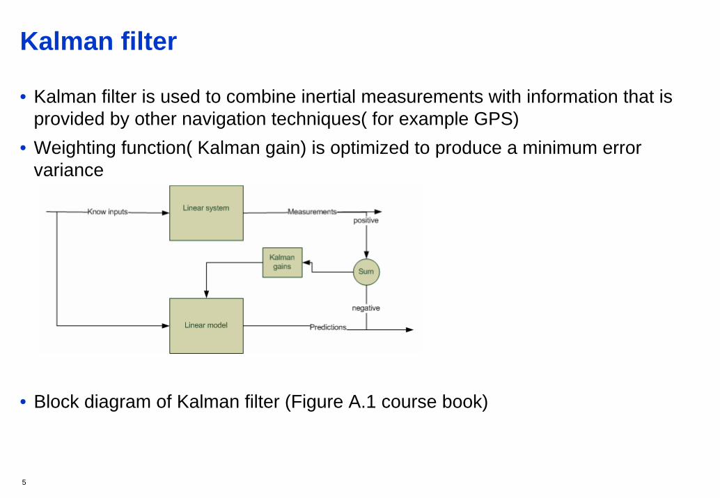
Kalman filter
• Kalman filter is used to combine inertial measurements with information that is provided by other navigation techniques( for example GPS)
• Weighting function( Kalman gain) is optimized to produce a minimum error variance
• Block diagram of Kalman filter (Figure A.1 course book)

6
Application of Kalman filtering to aided inertial navigation system• A missile on-board inertial navigation system • There are inertial navigation system in the missile • Also missile is tracked by a multi-function radar. Measurements are transmitted
via an uplink transmitter to the missile. • Kalman filter is used for combining transmitted measurements with
measurements provided by missile’s inertial navigation system. • Kalman filter makes to possible to estimating missiles position using noisy
measurement data. Also with Kalman filter it is possible to get estimates of errors in the states of navigation system.
• A nine state Kalman filter is required to get estimate of the three attitude errors, the three velocity errors and the three position errors.

7
Block diagram of missile INS application
• Based on course book figure 13.15

8
The system equations 1
• A linear dynamic model of errors is needed to formulate an extended Kalman filter. • The error model is expressed in matrix form:
• (1)
• The error state of the system is represented using vector • Components of are three attitude errors Three velocity errors Three position errors • It is needed to express the system error equation (1) to discrete form to construct discrete
Kalman filter
GwxFx += δδ.
xδ ),,( δγδβδα),,( zyx vvv δδδ
xδ
),,( zyx δδδ
9
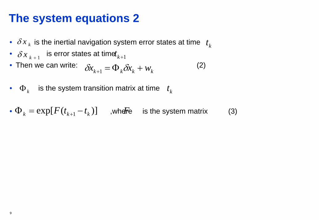
The system equations 2
• is the inertial navigation system error states at time • is error states at time • Then we can write: (2)
• is the system transition matrix at time
• ,where is the system matrix (3)
ktkxδ
1+kxδ 1+kt
kkkk wxx +Φ=+ δδ 1
kΦ kt
)](exp[ 1 kkk ttF −=Φ + F
10
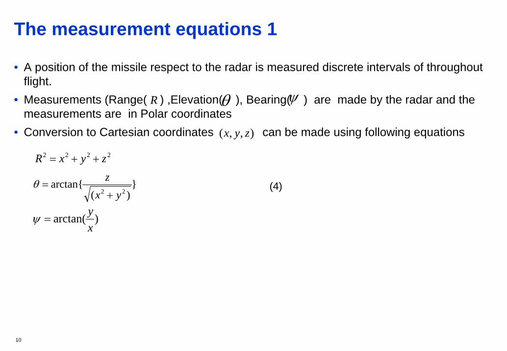
The measurement equations 1
• A position of the missile respect to the radar is measured discrete intervals of throughout flight.
• Measurements (Range( ) ,Elevation( ), Bearing( ) are made by the radar and the measurements are in Polar coordinates
• Conversion to Cartesian coordinates can be made using following equations
(4)
R θ ψ
),,( zyx
2222 zyxR ++=
})(
arctan{22 yx
z+
=θ
)arctan(xy
=ψ

11
The measurement equations 2
• When writing , the radar measurements can be typed as(5)
• n is a Gaussian zero mean white noise process that represents the measurement error
• Radar measurements can be estimated using inertial navigation measurements following way
•(6)
• It is possible to calculate difference between radar measurements and inertial sensor estimates (the filter measurement innovation)
• (7)
TRz ],,[ ψθ=
nzz +=~
nzz +=~
TxyT
yxzzyxRz })arctan{},
ˆˆˆ
arctan{,)ˆˆˆ(()ˆ,ˆ,ˆ(ˆ ˆˆ
22
222
+++== ψθ
xHzzz δδ =−= ˆ~
12
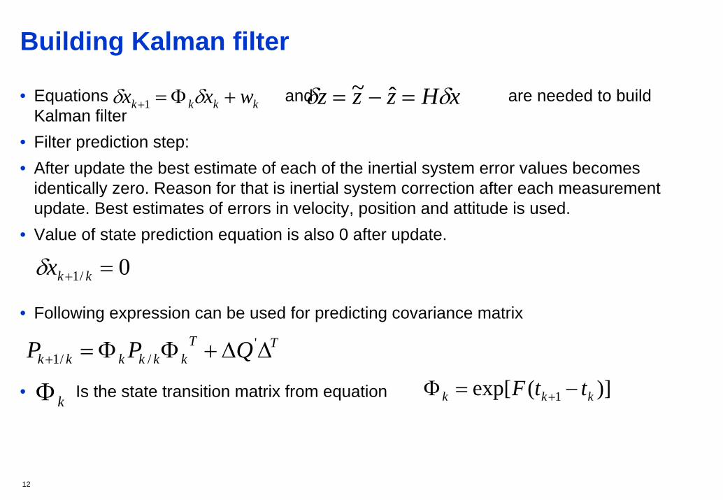
Building Kalman filter
• Equations and are needed to build Kalman filter
• Filter prediction step:• After update the best estimate of each of the inertial system error values becomes
identically zero. Reason for that is inertial system correction after each measurement update. Best estimates of errors in velocity, position and attitude is used.
• Value of state prediction equation is also 0 after update.
• Following expression can be used for predicting covariance matrix
• Is the state transition matrix from equation
kkkk wxx +Φ=+ δδ 1 xHzzz δδ =−= ˆ~
0/1 =+ kkxδ
TTkkkkkk QPP ΔΔ+ΦΦ=+
'//1
kΦ )](exp[ 1 kkk ttF −=Φ +
13
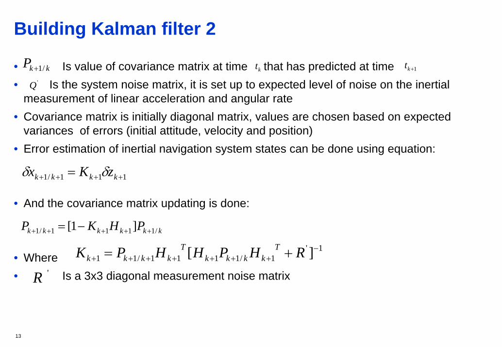
Building Kalman filter 2
• Is value of covariance matrix at time that has predicted at time• Is the system noise matrix, it is set up to expected level of noise on the inertial
measurement of linear acceleration and angular rate• Covariance matrix is initially diagonal matrix, values are chosen based on expected
variances of errors (initial attitude, velocity and position)• Error estimation of inertial navigation system states can be done using equation:
• And the covariance matrix updating is done:
• Where • Is a 3x3 diagonal measurement noise matrix
kkP /1+ kt 1+kt'Q
111/1 ++++ = kkkk zKx δδ
kkkkkk PHKP /1111/1 ]1[ +++++ −=
1'1/1111/11 ][ −+++++++ += RHPHHPK T
kkkkT
kkkk
'R

14
Inertial navigation system correction (Velocity and position)• Correcting the inertial navigation states ( ) is done after each measurement update.• The current best estimates of errors are used• Velocity and position correction is done subtracting the estimated error from the inertial
system estimates
• Is the corrected state
x̂
xxxc δ−= ˆ
cx

15
Attitude correction
• Attitude correction is done using following equations
• Is the corrected direction cosine matrix.• Where
• When writing and in component form and it is possible to write the estimated quaternion parameters directly using:
CC ]1[ˆ Ψ−=
cC CC cˆ]1[ Ψ+=
×=Ψ ψ T],,[ δγδβδαψ =
cC C ],,,[ ccccc dcbaC = ]d̂,ˆ,ˆ,ˆ[ cbaC =
)ˆˆˆ(5.0ˆ)ˆˆˆ(5.0ˆ
)ˆˆˆ(5.0ˆ)ˆˆˆ(5.0ˆ
abcdd
badcc
cdabb
dcbaa
c
c
c
c
δγδβδα
δγδβδα
δγδβδα
δγδβδα
+++=
++−+=
++−+=
+++=

16
Integrating GPS with inertial sensors
• Combining good sides of satellite navigation and inertial sensor navigation• Possibility to achieve better precision than using only GPS or only inertial sensors• Advantages of inertial navigation system: High data rate, provides both
translational and rotational data, not possible to jam inertial navigation system• Disadvantages of inertial navigation system: unbounded errors, knowledge of
gravity required and high cost of sensors • Advantages of satellite navigation systems: errors are bounded• Disadvantages of satellite navigation systems: Low data rate, no attitude
information, satellite navigation signals vulnerable for jamming

17
Different ways to integrate sensor with GPS
• Uncoupled system: INS indicated position is reset regular time intervals and position is replaced with GPS position
• Loosely coupled system: INS and GPS position and velocity is first calculated separately. Then INS and GPS estimates of position and velocity are compared. The position and velocity difference in input to a Kalman filter.
• Tightly coupled system: GPS measurements of pseudo-range and pseudo-range rate are compared with Inertial system made estimates of these quantities
• Deep or ultra-tightly coupled system: The GPS signal tracking function and theINS/GPS integration is combined into a single algorithm.
18
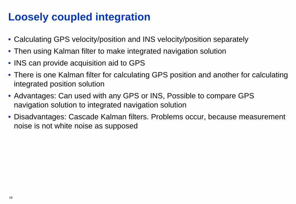
Loosely coupled integration
• Calculating GPS velocity/position and INS velocity/position separately• Then using Kalman filter to make integrated navigation solution • INS can provide acquisition aid to GPS • There is one Kalman filter for calculating GPS position and another for calculating
integrated position solution• Advantages: Can used with any GPS or INS, Possible to compare GPS
navigation solution to integrated navigation solution• Disadvantages: Cascade Kalman filters. Problems occur, because measurement
noise is not white noise as supposed

19
Loosely coupled integration block diagram
• Block diagram of loosely coupled integration based on course book figure 13.18

20
Tightly coupled integration
• Using single Kalman filter to calculate position.• The Kalman filter takes GPS pseudo-range/delta range measurements and INS
measurements as input and then calculated integrated navigation solution• Corrected or INS data can be used for aiding GPS • Benefits compared to loosely coupled integration
• Only one Kalman filter in the System, no problem with using output of Kalman filter as measurement input to another Kalman filter.
• GPS can be used to aid INS navigation system, thought no a full GPS solution (at least four satellites in view)
• Also it is possible to calculate GPS only position solution for example to make integrity monitoring and compare GPS only solution to integrated solution

21
Block diagram of tightly coupled integration
• Based on course book figure 13.19

22
End
Any questions ?