Author, Aalto Behavioral Laboratory Introduction to ME6000 ...
LM SC- A9800 3068 VOLUME II
DECE/kBER 14, 1970 1tI N77-775 3 1..(NASA-CR-11564W8 NEG ED MEDICAL AND
BEHAVIORAL LABORATORY MEASUREMENT SYSTEM. VOLUME 2: SYSTEM CONSIDERATIONS Final
-UnclasReportO(Lockheed missiles and Space Co.) _00/12 26652I7_
INTEGRATED MEDICAL AND BEHAVIORAL LABORATORY
ow PE0 MEASUREMENT SYSTEM ",4'
, cl0 1,
Final Report For E4 M PHASE B.4 PROJECT DEFINITION
(CONTRACT NAS910742) .
VOLUME II ,
.- SYSTEM CONSIDERATIONS IYH
jj
tnIm I I - .,
zHro OFFICE OF PRIflL RESPONiBBILIT
REPRODUCED BVI ' -
NATIONAL TECHNICAL - -JNFORMATION SERVICE
U.S. DEPARTMENT OF COMMERCE SPRINGFIELD, VA. 22161
LOCKHEED MISSILES & SPACE COMPANY A GROUP DIVISION OF LOCKHEED AIRCRAFT CORPORATION
SPACE SYSTEMS DIVISION SUNNYVALE, CALIFORNIA

LMSC-A980306 Volume II
December 14, 1970
FINAL REPORT FOR
INTEGRATED MEDICAL AND
BEHAVIORAL LABORATORY
MEASUREMENT SYSTEM
(IMBLMS)
Phase B. 4 Project Definition
-Volume II
SYSTEM CONSIDERATIONS
I
LOCKHEED MISSILES & SPACE COMPANY

IMBLMS
The National Aeronautics and Space Administration is sponsoring studies to develop
an Integrated Medical and Behavioral Laboratory Measurement System. IMBLMS
will be a highly flexible, state-of-the-art system, capable of acquiring, displaying,
analyzing, and recording a wide variety of medical, biochemical, microbiological,
and behavioral,measurements and experiments designed to study in detail man's
well being and operational capability during long-duration space missions. IMBLMS
also includes a comprehensive clinical capability for conducting routine physical
examinations and providing treatment in the event of injuries or other medical
emergencies.
IMBLMS work stations and peripheral equipment modules are designed for ease of
maintenance and adaptability of the measurements and experiments to meet changing requirements, based on the trend analysis of previously collected data and the
development of more advanced measurement techniques.
As evolved through several study phases, IMBLMS'consists of two major work
stations -biomedical/behavioral -and biochemical-and a variety of peripheral systems
and equipment. Major items of peripheral equipment include a lower body negative
pressure device, a bicycle ergometer, and a rotating litter chair. Central to IMBLMS
operations is a data management system, which provides for controlling, processing,
recording, and transmitting information derived from the various measurements.
The major measurement categories are as follows:
Neurological and sensory Microbiological
Cardiovascular Biochemical
Metabolic Behavioral
Respiratory Clinical
LOCKHEED MISSILES & SPACE COMPANY

Deployment of IMBLMS will involve the development of baseline data in all measure
ment areas. Primary emphasis is placed on detection and evaluation of incipient
problems that may occur with extended manned spacecraft missions. Flexibility
in measurement capabilities, scheduling, and interpretations is essential to an
effective program in order to focus on specific findings.
The first flight version of IMBLMS is intended for use on the first Space Station both as an experiment and as a clinical facility. Because of its compactness and
scientific potential, it is also suitable for use in any of the planned manned space
vehicles, such as Skylabs or an interplanetary craft. Furthermore, its dual role of
scientific experiment and clinical facility makes it a logical candidate for use on lunar bases and, pf impressive-spinoff'value, in earth-based medical facilities.
MMICROB IOLOGY STATI ON
•I"I|I|{ BIOCHEMICAL STATION
" .BIOMED ICAL STATION
WORNJill",BODY' SENSORS
t - I -PERIPHERAL
: | :..EQUI- PMENT
CLINICAL FACILITY EXPERIMENT AREA
ii
LOCKHEED MISSILES & SPACE COMPANY
LMSC-A980306
~NOT
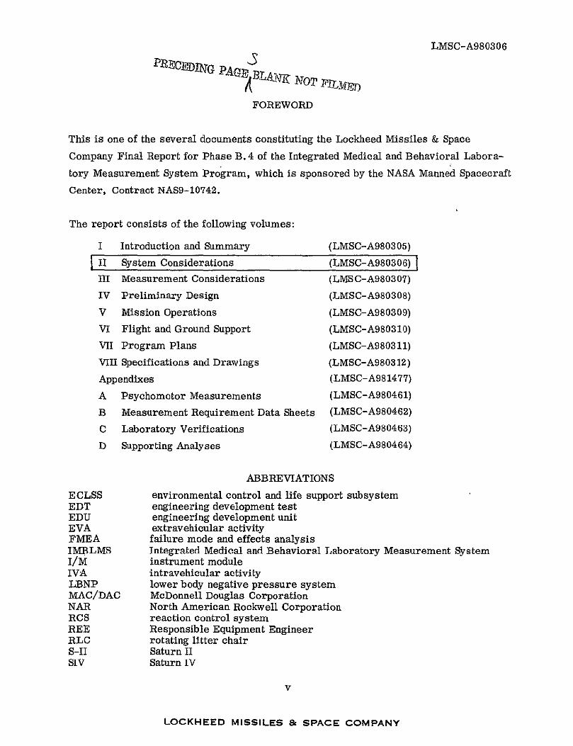
FOREWORD
This is one of the several documents constituting the Lockheed Missiles & Space
Company Final Report for Phase B. 4 of the Integrated Medical and Behavioral Labora
tory Measurement System Program, which is sponsored by the NASA Manned Spacecraft
Center, Contract NAS9-10742.
The report consists of the following volumes:
I Introduction and Summary (LMSC-A980305)
II System Considerations (LMSC-A980306)
III Measurement Considerations (LMSC-A980307)
IV Preliminary Design (LMSC-A980308)
V Mission Operations (LMSC-A980309)
VI Flight and Ground Support (LMSC-A980310)
VII Program Plans (LMSC-A980311)
VIII Specifications and Drawings (LMSC-A980312)
Appendixes (LMSC-A981477)
A Psychomotor Measurements (LMSC-A980461)
B Measurement Requirement Data Sheets (LMSC-A980462)
C Laboratory Verifications (LMSC-A980463)
D Supporting Analyses (LMSC-A980464)
ABBREVIATIONS
ECLSS environmental control and life support subsystem EDT engineering development test EDU engineering development unit EVA extravehicular activity FMEA failure mode and effects analysis IMBLMS Integrated Medical and Behavioral Laboratory Measurement System I/M instrument module IVA intravehicular activity LBNP lower body negative pressure system MAC/DAC McDonnell Douglas Corporation NAR North American Rockwell Corporation RCS reaction control system REE Responsible Equipment Engineer RLC rotating litter chair S-II Saturn II SIV Saturn IV
v
LOCKHEED MISSILES & SPACE COMPANY

LMSC-A980306Volume II
PRECEDING PAGE BLANK NOT FII EI
CONTENTS
Section Page
I INTRODUCTION 1-1
2 HOST SYSTEM CONSIDERATIONS 2-1
2. 1 Space Station 2-1
2. 1. 1 Configuration 2-1
2.1.2 Operations 2-6
2.1.3 Environment 2-11
2.2 Skylab 2-14
2. 2. 1 Configuration 2-14
2.2.2 Operations 2-14
2.2.3 Environment 2-16
2.3 Space Shuttle 2-17
2.4 Other I1BLMS Hosts 2-17
3 SPECIFIC IMBLMS CONSIDERATIONS 3-1
3. 1 Phases C/D Groundrules 3-1
3. 1.1 Program Plan Summary 3-1
3.1.2 Testing 3-1
3. 1. 3 Skylab Equipment Utilization 3-2
3. 2 Functional Objectives 3-2
3.3 Design Groundrules 3-4
3.4 Operability 3-5
3.4. 1 Reliability and Maintainability 3-5
3.4.2 Safety 3-7
4 IMBLMS/HOST VEHICLE INTERFACES 4-1
4. 1 IMBLMS/Space Station Interface 4-1
4. 1. 1 Structural and Mechanical 4-1
4. 1.2 Electrical 4-3
4. 1.3 Information Management 4-3
4.1.4 Environmental Control 4-4
vii
LOCKHEED MISSILES ,& SPACE COMPANY

LMSC-A980306 Volume II
Section Page
4.2 IMBLMS/Skylab Interface 4-6
4.2. 1 Structural and Mechanical 4-6 4.2.2 Electrical 4-8
4.2.3 Information Management 4-8
4.2.4 Environmental Control 4-8 5 SCHEDULE 5-1
viii
LOCKHEED MISSILES & SPACE COMPANY
LMSC-A980306 Section 1
Section 1
INTRODUCTION
IMBLMS is being developed for use aboard any manned space vehicle. It is important
therefore to consider briefly the configurations, operations, and environments of the
potential host vehicles and the IMBLMS relationship with the pertinent systems. This
relationship is discussed in this volume with respect to the Space Station, the Skylab,
and the Space Shuttle.
1-1
LOCKHEED MISSILES & SPACE COMPANy

LMSC-A980306Section 2
Section 2
HOST SYSTEM CONSIDERATIONS
2.1 SPACE STATION
NASA has been studying Space Station designs for nearly a decade and has recently
sponsored a series of Phase B Space Station definition studies. North American
Rockwell (NAR) has one contract, monitored by NASA/MSC, and McDonnell-Douglas
(lAC/DAC) has another, monitored by NASA/MFSC. Their reports provide the basis
the most of the information presented in this section.
2. 1. 1 Configuration
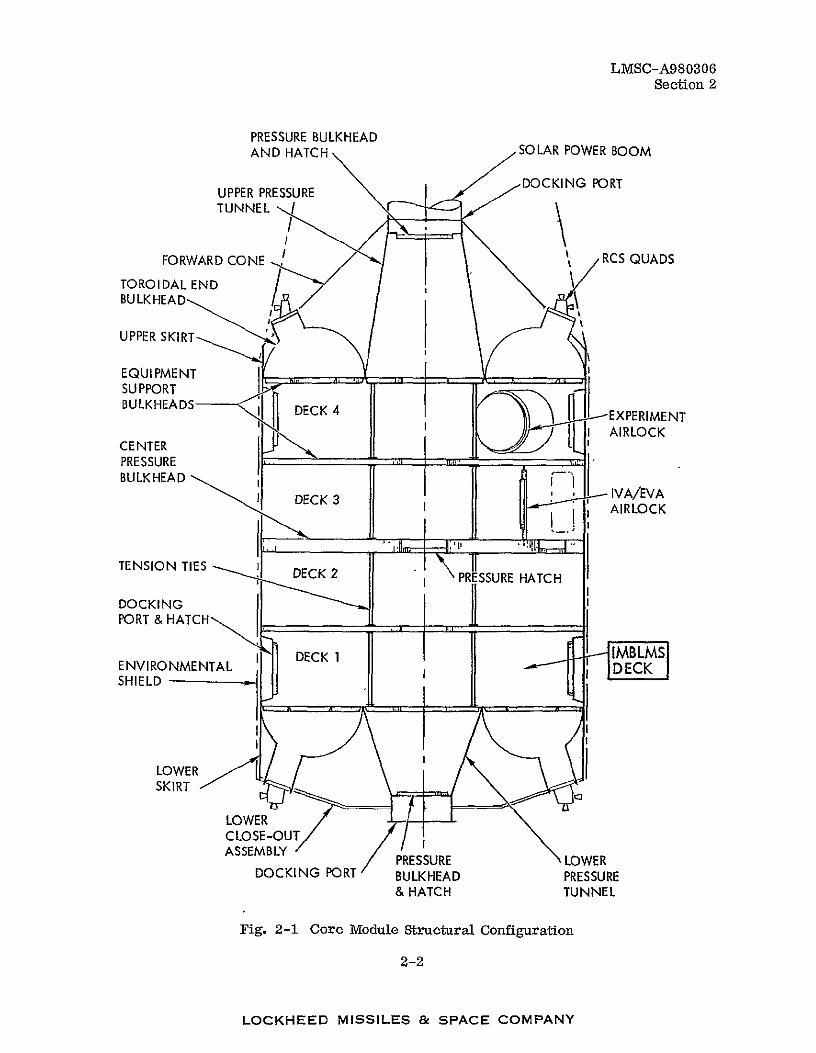
The general structural configuration of one design, shown in Fig. 2-1, is typical of all
of those evolved in the Phase B definition studies. The four-deck area is about 33 ft in
diameter and 35 ft long. Decks 1 and 2 have one pressure volume and 3 and 4 another.
In this concept IMBLMS will occupy about half of Deck 1; in another design, it will
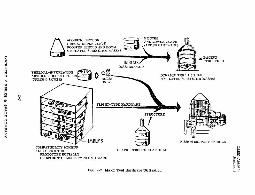
occupy half of Deck 2. The associated major hardware for test and mission support is
shown in Fig. 2-2. An IMBLMS prototype is to be integrated into the ground intergration
test article, which is a compatibility mockup; one of the IMBLMS flight units will sub
sequently be integrated into the mission support vehicle.
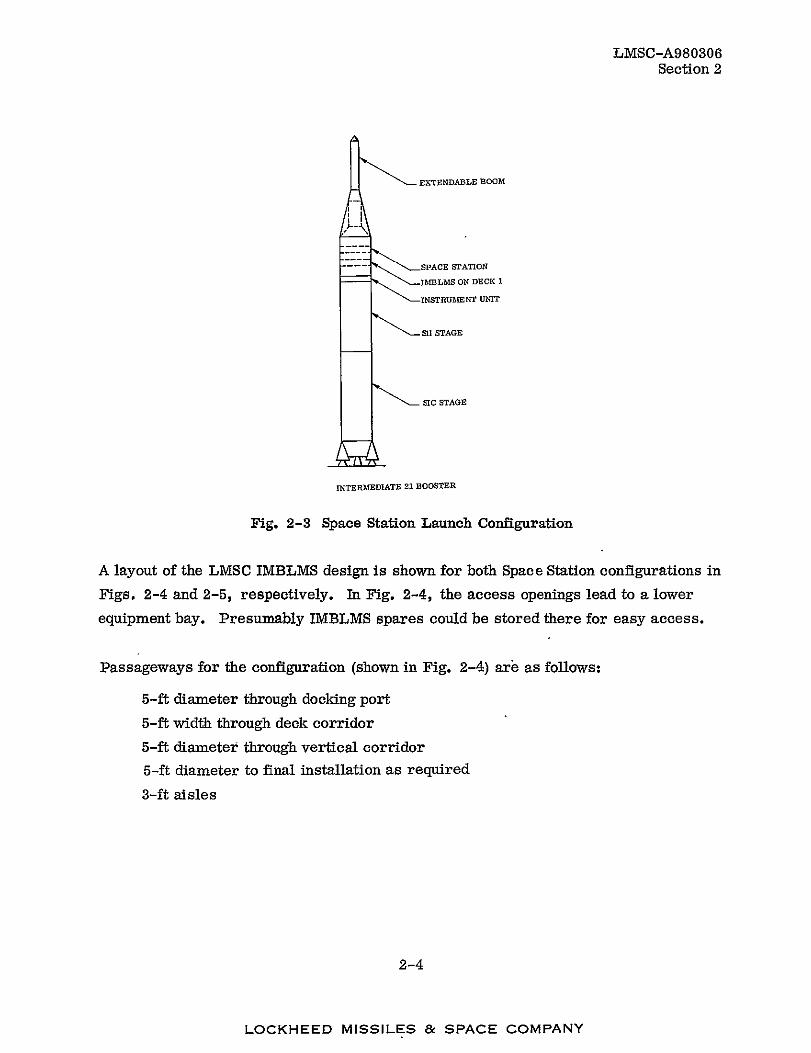
The launch configuration is shown in Fig. 2-3. The booster was adopted from the
Saturn V by removing the SIV stage.
2-1
LOCKHEED MISSILES & SPACE COMPANY
LMSC-A980306 Section 2
PRESSURE BULKHEAD AND HATCH SOLAR POWER BOOM
PORTUPPER PRESSURE
TUNNEL "
FORWARD CONE RCS QUADS
TOROI DAL END BULKHEAD/
UPPER SKIRT
EQUIPMENT SUPPORT BULKHEADS DECK4 EXPE
'I) '' I AIRLOCK
CENTER PRESSURE BULKHEAD
DECK 3L V/AL_.!AIRLOCK
T"ENSION TIES DECK 2 ,PRESSU RE HATCH
DOCKING PORT & HATCH,,,,,,!,.-._,
D DECK
IENVIRONMENTAL SHIELD
LOWER SKIRT
LOWER CLOSE-OUT ASSEMBLY PRESSURE LOWER
DOCKING PORT BULKHEAD PRESSURE & HATCH TUNNEL
Fig. 2-1 Core Module Structural Configuration
2-2
LOCKHEED MISSILES & SPACE COMPANY
ACOUSTIC SECTION AND LOWER TORUST ELOWRJADUPPER TORUS1 DECK, (AED HARDWARE
BOOSTER SHROUD AND BOOM
0 SIMULATED SUBSYSTEM MASSES lII
r I BACKUP ;o IMBLMS '
-SI
= STRUCTURE Q MASS MOCKUP
mq THERMAL-INTEGRATION E
O ARTICLE 2 DECKS + TORUS DYNAMIC TEST ARTICLE SIMULATED SUBSYSTEM MASSESONLSSS(UPPER & LOWER)
r Ito
r FLIGHT-TYPE HARDWARE
STRUCTUREm
0
I _
i B LN SMISSION, SUPPORT VEHICLE
COMPATIBIUITY MOCKUP ALL SUBSYSTEMS STATIC STRUCTURE ARTICLE
PROTOTYPE INITIALLYo UPDATED TO FLIGHT-TYPE HARDWARE
Fig. 2-2 Major Test Hardware Utilization
o D
Co
LMSC-A980306 Section 2
EXTENDABLE BOOM
SPACE STATION
I*MLMS ON DECK 1
INSTRUMENT UNIT
2I STAGE
SIC STAGE
INTERMEDIATE 21 BOOSTER
Fig. 2-3 Space Station Launch Configuration
A layout of the LMSC IMBLMS design is shown for both Space Station configurations in
Figs. 2-4 and 2-5, respectively. In Fig. 2-4, the access openings lead to a lower
equipment bay. Presumably IMBLMS spares could be stored there for easy access.
Passageways for the configuration (shown in Fig. 2-4) are as follows:
5-ft diameter through docking port
5-ft width through deck corridor
5-ft diameter through vertical corridor
5-ft diameter to final installation as required
3-ft aisles
2-4
LOCKHEED MISSILES & SPACE COMPANY

LMSC-A980306
Section 2
(O GUCEESS TO IMBLMS
SSMBCRO BIOC ICM
CLUNICAL -i N . SL DNG .
STO AGE E I.AND TORA1' TODEIRFE
LOCKHEDAE ISILS BE COMEANY
AREAEEI
SUBJECTIN CHAIR
M AREA-I*TREATMEN TABLE
Fig. 2-4 IBL1MS/Clinical Layout for Space Station (NARl)
ERGSTORED "--
E- ORA ,IIOAL EE .BMMDC - BEICRO/BIOCHEM
TRATREN TAOMEARTDENT
IAC SVWD "BL/
TREAMENTABL D_ MICR
_ _
STRG NEI UNT!BPFEZR
Fig. 2-5 IMBLMS/Clinical Area for Space Station (1MAC/DAC)
2-5
LOCKHEED MISSILES & SPACE COMPANY

LMSC-A980306
Section 2
2.1.2 Operations
The Space Station will be launched, unmanned, with a gross launch weight of over
192, 000 lb and follow an initial sequence of events similar to the following:
Day Activities
1 to 4 Station is unmanned while fuel residuals into space.
are safely vented
4 After safing and subsystem status verification, the shuttle is launched with crew and supplies when the station orbital plane coincides with the shuttle launch site. Rendezvous with the station is achieved in 6 to 24 hr. The shuttle then circumnavigates the station for visual inspection.
5 The crew/cargo module is extended from the shuttle and docked to the station. Crew and cargo are then transferred, an operation that can require as long as a day.
6 Equipment, such as IMBLMS, is activated and checked out and subsystems deployed as required. Manned operation begins, with the initial crew possibly remaining for as long as 6 months.
It will be injected at an altitude of 200 to 300 nm and an orbit inclination between 28. 5
to 55 deg with respect to the equator. The probable inclination is 55 deg, since this
maximizes earth coverage within that inclination band. Activities and phenomena
pertinent to an earth resources survey are shown in Fig. 2-6. Of these 90 percent
are covered at 55-deg inclination. The choice of altitude will largely depend on the
orbit earth trace desired. At 274 nm, the trace repeats daily; at 244 nm, the trace
repeats every 6 days. If 274 in is used, with the trace over the shuttle launch site,
this will facilitate emergency return of patients from the IMBLM clinical facility.
2-6
LOCKHEED MISSILES & SPACE COMPANY

LMSC-A980306 Section 2
EARTH RESOURCES AGRICULTURE FORESTRY
METEOROLOGY r*' NOTES: " , OCEANOGRAPHY
I& % 0 OCCURRENCE OR ACCEPTABLE ESE PREDOMINANT OR PREFERRED
I -a En c
80, - c 6,K f
W cc
70Q0
000
Fig. 2-6 Distribution of Earth Resources
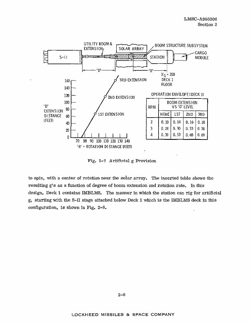
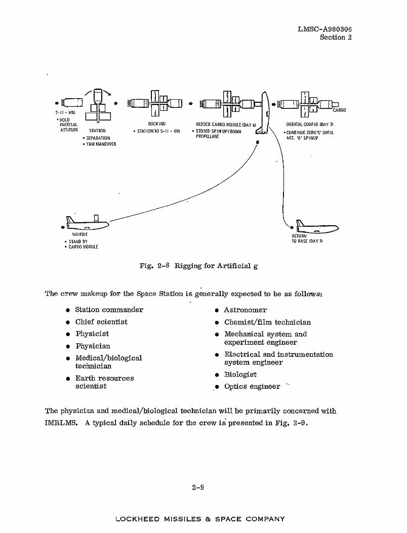
IMBLMS is to operate i~n the range f'rom' 0 to 1 g. For artificial g operation, one proposed
procedure is illustrated in Fig. 2-7. The S-Il launch stage is positioned on the end of an extendable boom, where it acts as a counterweight. The assembly can then be made
2-7
LOCKHEED MISSILES & SPACE COMPANY
LMSC-A980306 Section 2
UTILITY BOOM& BOOM STRUCTURE SUBSYSTEM
CARGO T -I S.TATION MODULE
D' - --'R'-"
XS =200
160 - 3RD EXTENSION DECK 1 FLOOR
140
120 -- 2ND EXTENSION OPERATION ENVELOPE (DECK 1)
100 - BOOM EXTENSION 'D' RPM VS 'G'LEVEL EXTENSION 8 DISTANCE 60 / IST EXTENSION NONE 1ST 2ND 3RD
(FEET) 40 2 10 14 0.16 0.18
203 024 030 0.33 0.38
4 039 053 0.60 0.690 70 80 90 100 110 120 130 140
'R'= ROTATION DISTANCE (FEET)
Fig. 2-7 Artificial g Provision
to spin, with a center of rotation near the soiar array. The inserted table shows the
resulting g' s as a function of degree of boom extension and rotation rate. In this
design, Deck 1 contains IMBLMS. The manner in which the station can rig for artificial
g, starting with the S-II stage attached below Deck 1 which is the IMBLMS deck in this
configuration, is shown in Fig. 2-8.
2-8
LOCKHEED MISSILES & SPACE COMPANY
LMSC-A980306
Section 2
•HOLD
INERTIAL DOCKING CARGO D RBITAL CONFIG [DAY IREDOCK MODULE ATITUDE STATION• - • STORED CONT UNTILSTATION TOS-l IM, SPIN UPIDOWN INUE ZEROG'
* SEPARATION PROPELLANT ART. '6' SPINUP * YAW MANEUVER
SHUTTLE RTURN
* STANDBY TO BASE(DAY 7 * CARGOMODULE
Fig. 2-8 Rigging for Artificial g
The crew makeup for the Space Station is generally expected to be as follows:
* Station commander * Astronomer
* Chief scientist . Chemist/film technician
* Physicist * Mechanical system and
experiment engineer* Physician" 00 Electrical and instrumentationMedica/bioloiccI * technician system engineer
* Biologist Earth resources" scientist e Optics engineer
The physician and medical/biological technician will be primarily concerned with
IMBLMS. A typical daily schedule for the crew is presented in Fig. 2-9.
2-9
LOCKHEED MISSILES & SPACE COMPANY

LMSC-A980306 Section 2
PERSONAL HYGIENESLEEPING 8 HRS/DAY
EATING 2.5 HVDAY WORK - 10 HR/DAy
RECREATION EXERCISE AND MEDICAL
-2.5 HRS/DAY
Fig. 2-9 Typical Daily Schedule
LS10
LOCKHEED MISSILES 8c SPACE COMPANY
LMSC-A980306 Section 2
The work performed will include scientific and technological research, public services,
and further development of space flight capability. The crew will also service and
maintain unmanned satellites and, of course, serve as subjects for IMBLMS experiments.
Logistics support for IMBLMS will be provided by the Space Shuttle, for which a flight
will be scheduled every 45 to 90 days, depending on study assumptions. Since the cur
rent shuttle concept provides for less cargo capacity than was considered for the Space
Station studies, 45 to 60 days is a more probable range. Supplies, crew replacements,
equipment spares, and the like will be brought up and solid waste, specimens, samples
records, film, and data returned, as will crew members who have finished their tour.
A cargo container is docked to the station by the shuttle, the shuttle then returns to
earth, and the container remains as a pantry for the station crew. The mechanics of
removing it and docking a new one on the next shuttle visit require further consideration.
It could be ejected and picked up later by the shuttle, or the new container could be
docked at another port.
2. 1. 3 Environment
The Space Station environment in which IMBLMS must operate is presented in
Table 2-1.
2-11
LOCKHEED MISSILES & SPACE COMPANY

Table 2-1
IMBLMS DESIGN REQUIREMENTS
Environmental Factors Ground(Non-Operating) Launch/Ascent(Non-Operating) Orbital and Ground
(Operating)
F
Temperature (OF)
Pressure (psia)
Humidity (%RH)
-15 to 115
10 to 15.2
0 to 00 (c )
TBD(a)
14.7 40.3
21 to 76
65 to 75
10 to 15.2 (b )
21 to 76
Salt Fog Protectively packaged(c) NA NA
iii
o
U) r
Fungus Acceleration
Shock
(d)
(d)
All equipment to be certified as non-nutrient to fungus
Lateral - S g 0 to I g when rotating Axial - 3 g forward; 0.035 g max.
5 g aft transient 30-g, 11-ms pulse with NA half-sine pulse, per
0)
Wn Acoustics (d)
MIL-STD-810B 140 db overall from 4 to 9600 Hz
NA
o m o 0 9 > Z "<
Vibration (d) Random 20 to 50 Hz, 0.05 g2/Hz 50 to 100 Hz, 6 dB/octave
rise 100 to 500 Hz, 0.2 g2 /Hz 500 to 1000 Hz, 6 dB/octave
roll off " Overall, 15. 5 g (rms) Duration, 3-min along each of three mutually perpendicular axes. Sweep time-3 min on each axis
NA
c
(a)Information not available and not required for IMBLMS Phase B-4 (to be determined in Phase C) (b)For 48-hour non-operating pressure of 10 8 psia after a slow depressurization; test to 10-2 mm Hg is adequate (c)Protected by proper packaging against rain and saltfog until placed in space-vehicle controlled environment (d) Protectively packaged to avoid exceeding launch and ascent environment
Co

Table 2-1 (Cont.)
Environmental Factors Ground
(Non-Operating) Launch/Ascent (Non-Operating)
Orbital and Ground (Operating)
Vibration (Cont.) (d) Sine
Lateral
NA
rO 0
'iM
5 to 12 5 Hz, 0.25 in. DA (peak to peak) 12.5 to 400 Hz, 2.0 g (0 to peak)
Axial
(n r-M (n
Wthe -a>levels 0 M o 0 "UK
W
5 to 15 Hz, 0.25 in. DA (peak to peak) 15 to 400 Hz, 3.0 g (0 to peak)
At primary resonances of console, reduce input
to 0.5 g lateral and . 0 g axial
Sweep, 3 min/octave
z
(d) Protectively packaged to avoid exceeding launch and ascent environment
C
Co
CI)
LMSC-A980306 Section 2
2.2 SKYLAB
In the IMBLMS design effort, consideration has been given to the "probability of
IMBLMS being included in whole or in part in the second dry launch Saturn workshop
payload (Skylab B)... Accordingly, a flight system must be ready for spacecraft instal
lation no later than November 1973." The use of IMBLMS on Skylab would yield these
advantages:
(1) The necessary in-flight measurements could be made to predict man's performance in flights of longer duration.
(2) Much additional information could be collected to influence the Space Station design.
(3) The prototype testing of IMBLMS would ensure the most mature design for the Space Station.
2.2.1 Configuration
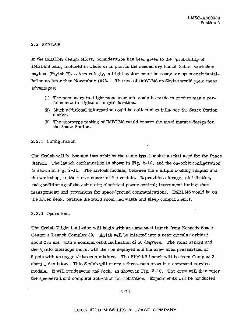
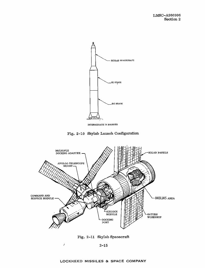
The Skylab will be boosted into orbit by the same type booster as that used for the Space
Station. The launch configuration is shown in Fig. 2-10, and the on-orbit configuration
is shown in Fig. 2-11. The airlock module, between the multiple docking adapter and
the workshop, is the nerve center of the vehicle. It provides storage, distribution,
and conditioning of the cabin air; electrical power control; instrument timing; data
management; and provisions for space/ground communications. IMBLMS would be on
the lower deck, outside the ward room and waste and sleep compartments.
2.2.2 Operations
The Skylab Flight 1 mission will begin with an unmanned launch from Kennedy Space
Center's Launch Complex 39. Skylab will be injected into a near circular orbit at
about 235 n, with a nominal orbit inclination of 50 degrees. The solar arrays and
the Apollo telescope mount will then be deployed and the crew area pressurized at
5 psia with an oxygen/nitrogen mixture. The Flight 2 launch will be from Complex 34
about 1 day later. This Skylab will carry a three-man crew in a command service
module. It will rendezvous and dock, as shown in Fig. 2-10. The crew will then enter
the spacecraft and complete activation for habitation. Experiments will be conducted
2-14
LOCKHEED MISSILES & SPACE COMPANY
L1VISC-A980306 Section 2
SKYLAB SPACECRAFT.
- Sl STAGE
SIC STAGE
INTERMEDIATE 21 BOOSTER
Fig. 2-10 Skylab Launch Configuration
MULTIPLE it
DOCKING ADAPTER SOLAR PANELS
COMMAND AND SERVICE MODULE
"""i AILOCK MODULE
PORT
IMBLMS AREA
kSTR STR WORKSHOP
Fig. 2-11 Skylab Spacecraft
2-15
LOCKHEED MISSILES & SPACE COMPANY
- -
LMSC-A980306 Section 2
for a nominal 28-day period, after which the crew will prepare the Skylab for orbital
storage. Nominally, they will deorbit in the command service module on the 29th
mission day for splashdown in the West Atlantic recovery area.
A second and third crew will visit the spacecraft and each remain for up to 56 days, for
a total of three missions.
At least one mission will have a qualified astronomer aboard, and the second mission
will probably have a physician as one of the three-man crew.
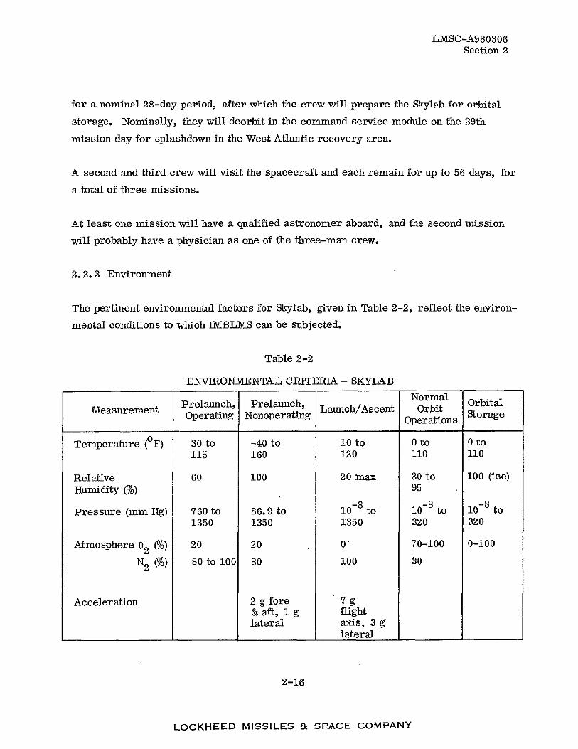
2.2. 3 Environment
The pertinent environmental factors for Skylab, given in Table 2-2, reflect the environ
mental conditions to which IMBLMS can be subjected.
Table 2-2
ENVIRONMENTAL CRITERIA - SKYLAB
Normal OrbitalMeasurement Prelaunch, Prelaunch Launch/AscentOperating Orbit oraNonoperating Operations Storage
Temperature ( F) 30 to -40 to 10 to 0 to 0 to 115 160 120 110 110
Relative 60 100 20 max 30 to 100 (ice) Humidity (%) 95
- 8 toPressure (mm Hg) 760 to 86.9 to 10 8 to 10 8 to 101350 1350 1350 320 320
Atmosphere 02 (To) 20 20 0 70-100 0-100
N2 (9o) 80 to 100 80 100 30
Acceleration 2 g fore 7 g & aft, 1 g flight lateral axis, 3 g
lateral
2-16
LOCKHEED MISSILES & SPACE COMPANY
LMSC-A980306 Section 2
2.3 SPACE SHUTTLE
The Space Shuttle will provide logistics support for IMBLMS and may, in fact, be used
to inject a modular-type station for assembly on orbit. Both shuttle stages are manned,
and the operational concept is shown in Fig. 2-12. At an altitude of about 40 nm, the
first stage separates and is flown back to base for refurbishment. The orbit element
continues to complete the mission, injecting into low-earth orbit a payload currently
estimated at 25, 000 lb. For cargo injection, however, about 30 percent of this weight
will be required for structure and subsystems.
One concept for a 12-man modular Space Station, which the Space Shuttle could inject
by repeated flights, is shown in Fig. 2-13. In this configuration, the IMBLMS/clinical
area will occupy one module. Possible IMBLMS layouts for such a station are illustrated
in Fig. 2-14.
The Space Shuttle brings a number of unique advantages to space operations. With
respect to IMBLMS, for example, it can offer the following:
(1) Deliver equipment to the station with much lower g loadings than by
conventional boosters, a reduction from about 5 to about 3 g.
(2) Provide an emergency service to return to earth ill or injured crew members.
(3) Bring non-astronaut passengers up to aid in IMBLMS experiments.
(4) Economically deliver IMBLMS spares and new or upgraded modules.
Since there is no planned constraint on launch azimuth, cargo capability need not be
reduced to provide fuel for dog-leg maneuvers. Passengers can be of normal health
without a requirement for extensive training or physical conditioning. The internal
atmosphere will be earth-like, with maximum accelerations less than three times
gravity.
2.4 OTHER IMBLMS HOSTS
Configurations of other NASA space vehicles in which IMBLMS could be used would in
clude interplanetary flight or lunar bases, as well as lunar space stations and stations
in earth geocentric orbit. They are not yet sufficiently defined to consider in any detail,
2-17
LOCKHEED MISSILES & SPACE COMPANY

ORBIT ELEMENT
r STAGING
00/ "/ BOOST ELEMENT ENTRY
(I)
mJ 0) 0 09l/2 LAUNCH BOOST ELEMENT CRUISE BACK 7' /
ORBIT ELEMENT CRUISE BACK
Fig. 2-12 Space Shuttle - Operational Concept 00

ELECTRICAL POWER BOOM
TWO HIGH-GAIN ANTENNAS
EXPENDABLES
SOLAR ARRAY
r 0 0
Mm
LoU)
FOUR CREW STATEROOMS
-- PRIMARY CONTROL TWO CREW STATEROOMS
r 4) ,W
RECREATION,AND DINING
GALLEY- - 12-MAN ECLSS
-g
rM ECLSS - - IMBLMS/CLINICAL EXERCISE
0 9 TU EXPERIMENT CONTROL/ -- FOUR CREW z TWO CREW STATEROOMS STATEROOMS
INTEGRAL EXPERIMENTS- -INTEGRAL EXPERIMENTS AND MAINTENANCE
ATTACHED EXPERIMENT- -DETACHED EXPERIMENT MODULE MODULE m
o C>
CO Fig. 2-13 12-Man Modular Space Station Concept=

DIJDATA
r -CROD-lAHT AREA OPT u.E BEIM
LEND _ _ _ __BDI M L
IMBDLMSAJILA145E
0 EG
[1 00
Fig.~~~~~~~~~~~~~~Dragmnsfr1-a 2-4IBM pc Tato CocetRo
DECKSMC
PLD lN DECK 3
.A2a

LMSC-A980306 Section 2
but they should be similar in design to the Space Station. Another interesting host
vehicle for the future is the 60-man Space Base, of which a possible design is illustrated
in Fig. 2-15. The Y-like attachment contains the nuclear power source, and each of
the four modules attached to a center core is equivalent to one for the Space Station
concept. IMBLMS would grow in size, occupying the indicated deck.
Then, too, there is the possible use of IMBLMS on earth, where it might be modified
into a small and efficient mobile clinic to reduce the burden on present public health
facilities. A more complex IMBLMS, stationed at central locations, could support the
field IMBLMS. *
I MM- LM Dv
IMBLMS DECK
Fig. 2-15 Space Base Configuration
*The NASA Program for an Integrated Medical and Behavioral Laboratory Measurement System, N. Belasco and S. L. Pool, M.D., NASA MSC, Houston, Texas
2-21
LOCKHEED MISSILES & SPACE COMPANY

LMSC-A980306 Section 3
Section 3
SPECIFIC IMBLMS CONSIDERATIONS
3.1 PHASES C/D GROUNDRULES
The groundrules for Phases C/D, submitted to LMSC during Phase B. 4, call for a
reduction in the number of hardware end items and testing requirements, emphasizing
the use of Skylab-developed items.
3. 1. 1 Program Plan Summary
During Phase C, the effort will center on the design and development of an engineering
development unit (EDU). Aside from documentation, the major tasks will be as follows,
with the work performed sequentially:
(1) Complete the design of and fabricate an EDU
(2) Conduct engineering development tests on the EDU
(3) Update and optimize the EDU flight design
(4) Update the EDU to that design
(5) Integrate the EDU into the ground integration test article
In Phase D, these additional major tasks will be performed:
(1) Manufacture a mass mockup
(2) Manufacture two flight units, one for the mission support vehicle and one for the flight vehicle (the former to be used for backup and training)
(3) Provide operational support
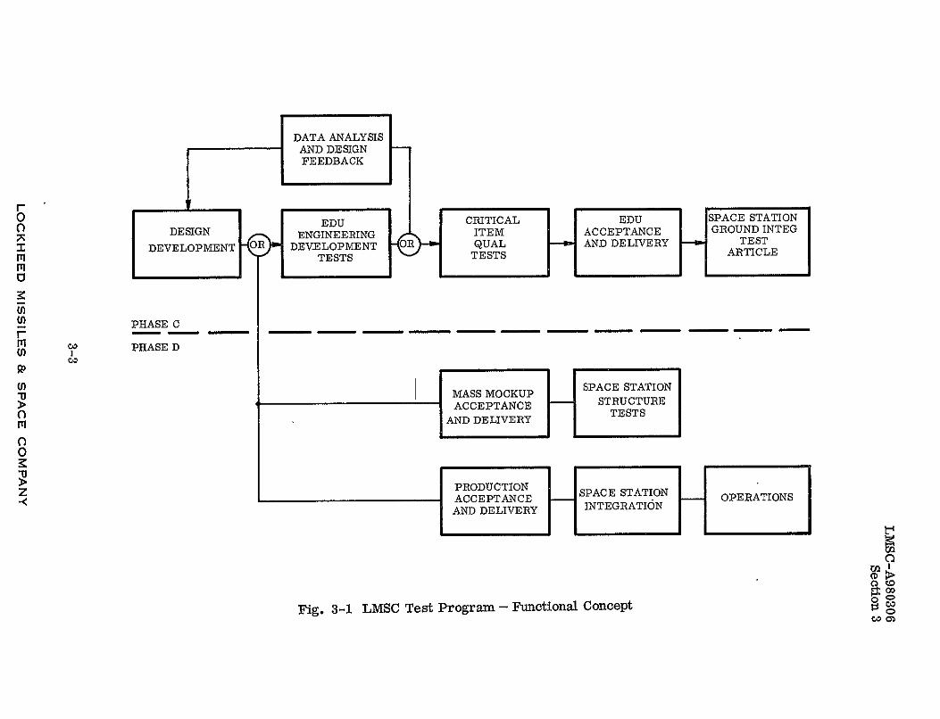
3.1.2 Testing
Qualification testing will be conducted specifically on items critical to safety or total
mission success. For the remaining items, qualification test disciplines are integrated
into the total test program. A qualification/certification matrix will be established to
3-1
LOCKHEED MISSILES & SPACE COMPANY

LMSC-A980306 Section 3
ensure qualification by analysis and similarity considerations. The functional concept
of the LMSC test program is illustrated in Fig. 3-1; the test plan is presented in
Volume VII of this report.
3. 1. 3 Skylab Equipment Utilization
Utilization of Skylab equipment will be to the maximum extent possible. For example,
the bicycle ergometer and mass measuring devices are being modified only to the ex
tent necessary to integrate them into the IMBLMS stations. In addition, the lower
body negative pressure equipment is being modified to servie the additional function
of measuring total body volume.
3.2 FUNCTIONAL OBJECTIVES
IMBLMS will consist of the hardware and software required for the performance of
human physiological, laboratory analysis, and behavioral measurements and their
related data-handling functions; it will be flexible and modular in design to accommo
date changes in experiments and choice of host vehicle. Specifically, IMBLMS will
be capable of performing numerous measurements in the following areas:
Clinical Metabolic
Neurological and sensory Behavioral
Cardiovascular Microbiology
Respiratory Environmental
Laboratory analysis
In addition, the IMBLMS must contain a comprehensive clinical capability to diagnose
and treat a broad spectrum of mishaps, accidents, and diseases. The system will
be able to function in all environments encountered from prelaunch through orbital and
will be capable of sensing, processing, and displaying measurement data over a range
of operating modes.
IM1BLMS capabilities and equipment will comply with the following guidelines:
3-2
LOCKHEED MISSILES & SPACE COMPANY
DATA ANALYSIS AND DESIGNFEEDBACK
00
I iiii
DESIGN
DEVELOPMENT OR
EDOENGINEERING
DEVELOPMENT TESTS
B
CRITICAL ITEM QUAL
TESTS
EDO ACCEPTANCE AND DELIVERY
SPACE STATION GROUND INTEG
TEST ARTICLE
CD
M'iU) C3
PHASE C
PHASE D
MP 0
MASS MOCKUP
AND DELIVERY
STRUCTURE
SA TESTS
Z < PRODUCTIONACCEPTANCE
AND DELIVERY
STATIONOPERATIONS INTEGRATION
Fig. 3-1 LMSC Test Program - Functional Concept
rA
0CD
0
LMSC-A980306 Section 3
(1) Provision for evolutionary growth
(2) Utilization of general-purpose equipment, as practical
(3) Flexibility for change in measurement requirements
(4) Provision of automatic operation
3.3 DESIGN GROUNDRULES
Flexibility is imperative for IMBLMS; the long program life, variety of host vehicles,
richness of potential experiments, and long operating life demand that the IMBLMS
design be characterized by the following:
(1) Modularity - The functional support system capacity can be increased by adding system elements. Hence, the mix of medical experiments can be modified without adversely affecting the Space Station interface.
(2) Adaptability - The design permits changing the mission complement of medical experiments during resupply with minimum effort on the part of the crew.
(3) Fail/Safe Design - No IMBLMS failures will impair the safety of the crew, and no single experiment will adversely affect any other experiment.
(4) Design Conservation - The IMBLMS design incorporates flight-qualified components where they are available. Derating of components has been applied to new designs.
Continuing emphasis will be placed on minimum cost, but not at the expense of com
promise to crew safety or total mission success. Maximum use of developed items is
a firm requirement, not only those from Skylab but any suitable ones from government
and industrial programs.
Simplicity in equipment design has been stressed. Where less complex operation will
suffice without significant compromise in product effectiveness, it has influenced
design. Simplicity also tends to bring less demand on Space Station resources in terms
of weight and electrical power. Furthermore, it ensures greater reliability with less
demand on crew time for maintenance and repair. Thus, if a manually operated piece
of equipment is essentially as effective as a highly sophisticated and complex electronic
one, the former has been chosen.
3-4
LOCKHEED MISSILES & SPACE COMPANY
LMSC-A980306 Section 3
The IMBLMS design must also contribute to reducing setup, operating, and maintenance
time spent by the crew. This capability has been accomplished by the following means:
(1) Where practical, use of replaceable controls and displays that can be made
the same as those in the spacecraft
(2) Use of standard fault detection and isolation procedures for all experiments
(3) Establishment of line-replaceable units as the lowest level of replacement normally permitted, with fault isolation to the line-replaceable unit provided automatically
(4) Provision for adaptable calibration through computer programming that automatically scales the measurement, based on known calibration points
Finally, it must be emphasized again that flexibility is a key design objective of IMBLMS.
Further, IMBLMS will have the capability to accommodate future biomedical experiments
that may be submitted by the biomedical community without the need for extensive
engineering development to provide for such unique requirements. IMBLMS must be
able to accept any new medical experiment that might reasonably be conceived and make
it part of the integrated whole.
3.4 OPERABILITY
3.4.1 Reliability and Maintainability
The overall IMBLMS reliability goal is to carry out extended mission operations without
system failure. The corresponding maintainability goal is to make any necessary hard
ware replacements during predicted downtimes in accordance with predetermined sched
ules. A primary function is the reliability program to establish component capability
for long life while a complementary function in the maintainability program is to provide
for in-flight maintenance with fault isolation and replacement.
It is evident that reliability and maintainability must be considered together. The
essence of the combined program is as follows:
(1) Identify and control failure modes
(2) Conduct design reviews
3-5
LOCKHEED MISSILES & SPACE COMPANY
LMSC-A980306 Section 3
(3) Conduct an integrated development/acceptance/qualification test program
(4) Identify and correct production and test failures
The first and fourth items assure the element of dependability; the other two items
assure the elements of design capability and availability, or the measure of system
effectiveness.
The failure mode and effects analysis (FMEA) is a systematic, organized procedure
for identifying, evaluating, and analyzing potential failures in the system. From these
analyses, appropriate corrective action can be formulated to eliminate or mitigate the
effects of failure modes. The FIVIEA will uncover the need for design changes and im
provements and detect these needs at an early stage of the design, when they can be
most effectively accomplished.
Reliability and maintainability engineers, located in the design areas, will review
documentation continually as the design evolves. Parts specialists will assist with
criteria for parts and materials applications. Principal aims will be to design for
maximum component life by selection of established parts and materials and by circuit
simplification and parts deratilig, as well as full consideration of the future main
tenance actions. These reviews, together with the more formal design review meet
ings, will provide the optimum product design reliability and maintainability.
Assurance that the system and its components can meet all prescribed design and
performance requirements is the purpose of qualification. A qualification matrix
will be established. By judicious planning for development and acceptance testing,
as well as qualification testing itself, and by application of all available prior test
data, qualification will be accomplished in the most cost-effective manner.
Investigation of production and test failures will be thorough. By establishing the basic
cause for equipment failures, with diagnostic failure testing used where necessary,
corrective measures will be implemented to assure that the operational mission will be
accomplished.
3-6
LOCKHEED MISSILES & SPACE COMPANY
LMSC-A980306 Section 2
Assurance that the above procedures will be rigorously and comprehensively undertaken
is provided by the designation of a Responsible EquipmentEngineer (REE) to maintain
cognizance over each of one or more pieces of IMBLMS equipment. He will participate
in the design and monitor, all other activities from which an optimized engineering devel
opment unit will eventually emerge. He will be the principal point of contact for any
detailed information on his equipment.
3.4.2 Safety
The application of system safety techniques, such as hazards analysis and establishment
of design safety guidelines, in addition to stringent safety surveillance, will be employed
to assure the safety in all IMBLMS operations. Established system safety guidelines
will be used as configuration drivers to ensure that catastrophic and critical hazards
will be eliminated or controlled.
The basic IMBLMS safety requirements are as follows:
(1) IMBLMS will be compatible with the Space Station interfaces from the standpoint of physical and environmental safety.
(2) IMBLMS operations will in no way result in safety degradation in Space Station functions.
(3) IMBLMS will be designed for inherently safe care of-sick or injured personnel.
(4) The IMBLMS design will be in compliance with NASA-Manned Spacecraft safety criteria.
The primary electrical power source for IMBLMS will be from the Space Station.
Provisions will be made in IMBLMS design to prevent and control any possible over
load condition to preclude any possible interference with the Space Station operators.
RF energy radiated from body-worn telemetry for the acquisition of IMBLMS medical data will be energy-controlled to prevent injury to personnel and interference with the
Space Station.
The man-machine operational characteristics and design techniques will be considered
from a commonality and simplicity viewpoint. The sensing and monitoring devices used
3-7
LOCKHEED MISSILES &: SPACE -COMPANY

LMSC-A980306 Section 3
in the man-machine interface will be designed in accordance with NASA manned space
programs established practices.
The use of existing and new clinical equipment and instruments under zero gravity will
require the development of new hardline techniques and the application of personnel
injury prevention training programs. In addition, specialized equipment aids to mini
mize potential operational hazards will be important design considerations.
3-8
LOCKHEED MISSILES & SPACE COMPANY

LMSC-A980306 Section 4
Section 4
IMBLMS/HOST VEHICLE INTERFACES
4. 1 IMBLMS/SPACE STATION INTERFACE
Since the Space Station has not been firmly defined, precise interface data are not yet
available; indeed, the two candidate configurations differ markedly. The flexibility of
IMBLMS, however, ensures that it will be completely compatible with the final design.
Pertinent information made available to LMSC from North American Rockwell (NAR)
and McDonald/Douglas (Mc/D) reports is presented in the following paragraphs.
4. 1. 1 Structural and Mechanical
For the ascent mode, fixed IMBLMS equipment is installed and dynamic loads are
picked up through mounting flanges, attached to the deck. For the orbital mode, the
equipment will be prevented from shifting position by the same mounting flanges.
Under zero g, the equipment will remain in position in much the same manner as
equipment on the ground.
The Space Station area available for IMBLMS and the clinical facility are shown in plan
view in Fig. 4-1 for both design configurations. Key interface features are as follows:
(1) Deck mounting by tiedown
(2) Flexible location and relocation
(3) Overhead provision for utilities
(4) Movable partitions
4-1
LOCKHEED MISSILES & SPACE COMPANY

LMSC-A980306 Section 4
,ACCESS TO
MONTO: EDPAFERER
I
ST O RUAGE U ND ER)
SUBJERDICT StuORR/BOEEZE
MNITOR-T CHATIER
PIMERRFE INC RGI COMPARTMENTLE
TREATMENTTABLERACEEN T2L .L " I_-| AREA A OS
STORAGEUNE) MM
LTCKEEMIIE ' SPACEBCMAN
"ERG
IEHAim -- RAL
O4-2
Fig. 4-1 Two Candidate Configurations - IMBLMS/Clinioal Area in Space Station
4-2
LOCKHEED MISSILES & SPACE COMPANY

LMSC-A980306 Section 4
4.1.2 Electrical
Voltage characteristics for IMBLMS are as follows'
AC 120/208 volts, 3-phase, 400 lz
DC steady state 27.5 ±2.5 volts
Transient voltages 21 to 32 volts with recovery to steady state within 1 second
Ripple voltage 1 volt PP
Power failure up to 5 msec
4.1.3 Information Management
Information management system characteristics differ between the two configurations
as follows:
NAR MAC/DAC
Maximum expended data rate:
Onboard (bits/day) 1.58 x 10¹¹ 7.5 x 10¹¹
Realtime (bits/day) None 5 x 10¹¹
Delayed (bits/day) 2 x 10⁹ None
Tape and film (lb/day) 57 30
Ground communications:
Analog (MHz) 6.5 40
Digital (bits/sec) 5 x 10⁶ 10 x 106
Computer:
Operations/see 107 1.2 x 10⁶
Number of processors 5 6
Mass memory size (words) 2.5 x 10⁶ 7 x 10⁶
IMBLMS will have a hardline connection to the Space Station information management
system. This will be a logical connection with status and control lines. To be deter
mined are the amount of data and operations for station use. The data generated by
IMBLMS can be entirely self-contained or fed in whole or part to the Station, as
required.
4-3
LOCKHEED. MISSILES & SPACE COMPANY

LMSC-A980306
Section 4
External data links for the NAR Space Station configuration are shown in Table 4-1.
Table 4-1
SPACE STATION EXTERNAL COMMUNICATIONS LINKS (MSC)
Nomenclature DRSS Line Direct to Ground Remote Module 1 ogistics Up Link fown Link Up Link Don Link SS to m RM to SS SS to Log Log to SS
Digital data 1 X 10 6
bps 1x 10⁷
bps I X 106 bps 1 x 10⁷
bps Ix 10 4
bps Sx 10 6
bps Ix lO14
bps Ix 104
bps
Voice channels 4 at 4 KHl 4 at 4 lna 4 at 4 ElHz 4 at 4KH 1 at 4 KHz 1 at 4 TIM. 2 at4 ll 1 at4 RiZ
Audio 1 at 10 KHZ I at 10 Ri
Video 1 comm color at
1 comm color at
1 c. color at
1 comm color at
TV at 3 I06 H.
4.5 MI. 4.5 AM. 4.5 MHz 4.5 M1Hz
Trackn wraggPRU rel PNragn
B at sxlobps PPRranpngeatlxlO bps PRlrnglgPatlxlibps rangatlx106bps PtRINxrangaat PXrngIxO bps
4. 1.4 Environmental Control
Interface information pertinent to IMBLMS extracted from the Space Station Phase B Definition Study, MSC Compatibility Data for Contract NAS9-9953, Experiments Panel,
June 19, 1970, is as follows.
CO 2 Control
The Station shall maintain the atmosphere at 5 MMHG nominal CO 2 partial pressure. Non-metabolic, animal and experiment produced C02 shall be controlled by the experiment. CO 2 control for the crew shall be provided for integral, attached, and detached experiments.
Temperature Control
Integral Experiments - The Station shall provide selectable temperature control between 65 and 75 deg F for integral experiments. Capability shall be provided in the Experiments area on Deck 4 to supply air selectable between 60 and 75 deg F. The Station atmosphere shall accommodate 2250 watts of sensible heat maximum from the integral experiments. (Sized on the basis of 25 percent to the atmosphere of a maximum 9000 watts.)
Pressure Control
The Station shall provide total pressure control and oxygen partial pressurecontrol for integral, attached and docked detached modules to the same condition as the Station atmosphere. The Station and experiments atmosphere shall be controlled to 14.7 psia (with variation to 10 psia allowable) and oxygen partial pressure at 3.1 psia. Experiment pressure requitements different from the Station shall be provided by experiments.
4-4
LOCKHEED MISSILES & SPACE COMPANY
LMSC-A980306 Section 4
Contamination Control
Toxic, corrosive or bacteriological contaminants shall be removed by the experiments before the atmosphere is returned to the Station system. The Station contaminant control assembly may be utilized by experiments for the control of contaminants with maximum generation rates to be specified.
Humidity Control
The Station shall provide atmosphere at 8 to 12 MMHG partial pressure of water for integral, attached, and docked detached experiments. Humidity control to a different level shall be provided by the FPE. Excessive experiment caused humidity (greater than approx 0.5 lb/hr of non-human water to the atmosphere) shall be removed by experiment facilities.
Water Management
Storage and/or generation capability for supplying 35 lb/day maximum of potable water shall be provided by the Station ECLSS. The water shall have the same potability and purity requirements as the Station (NASA-MSC specification PF-Spec-lB-Command Module/Lunar Module potable water specification - 25 June 1969). This capability shall be provided for use by each experiment mode (integral, attached or detached). However, the combined use by the three modes at any one time shall not exceed the 35 lb/day limit.
ECLSS Prototype Experiments
The Station ECLSS subsystem distribution and controls shall be available for prototype functional and operational experiments. The prototypes must be capable of being integrated with/into the Station ECLSS in a manner such that the Station subsystem can take over operation in the event of any prototype malfunction.
Waste Management
The station shall provide capability for processing a total of 67 pounds per month of waste and trash material from experiments such as IMBLMS. This material will be vacuum dried and stored for return to earth.
For active thermal control, the MSC design has a coolant fluid outlet temperature of
35°F.
4-5
LOCKHEED MISSILES & SPACE COMPANY

LMSC-A980306 Section 4
4.2 IMBLMS/SKYLAB INTERFACE
4.2. 1 Structural and Mechanical
A plan view of the IMBLMS decks on Skylab, shown in Fig. 4-2, is a typical equipment
layout. Being highly flexible, IMBLMS can readily adapt to the area shown.
In Skylab, the basic experiment equipment is to be floor mounted. The auxiliary
equipment will be both floor and wall mounted.
The experiments associated with the scientific airlocks and the maneuvering experi
ments, together with their stowage containers, are to be located in the forward
compartment.
The environment sampling experiment is to be initially mounted on the forward side of
the ceiling (its most frequently used location). Mounting brackets will also be provided
in the head, the wardroom, and the sleep compartment. The experiment will be hand
held at all other sampling stations.
Heavy experiments will be located at points where the floor has its greatest load-bearing
capability.
Most experiments will be permanently installed at the location of their activities. All
installations are hard-mounted to the tank wall, crew quarters partitions, ceiling, or
floor. If shock mounting is required, the supplying contractor will provide the necessary
protection within his experiment or stowage container.
The attachments between the experiments and the support structure are to be oriented
to coincide with the standardized astrogrid, whether floor or wall, in order to standard
ize and minimize interface problems.
Provisions on the experiment mounting structure will be made for electrical bonding.
4-6
LOCKHEED MI-SSILES & SPACE COMPANY

ERGOMETER -Z
0
n o
-,- -- BEHAVIORALCONSOLE
BIOMED , A 0'
USECTION
(nLBNP r0M B
B-B
0 m
0
-u
78
_
S B -LBNP BEHAVIORAL
BIOMED
SECTION A-A
RLC BIOCHEM CONSOLE
+Z
Fig. 4-2 Skylab Plan View
onb
LMSC-A980306 Section 4
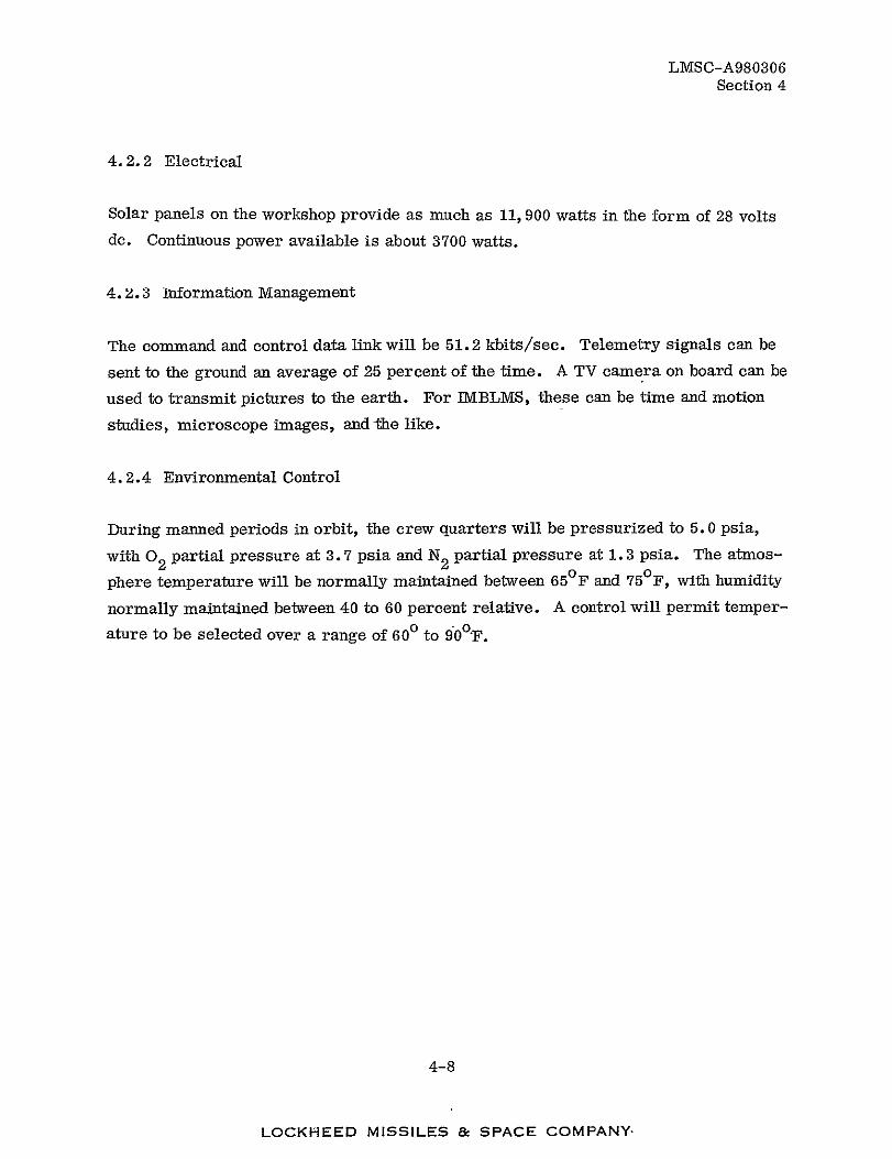
4.2.2 Electrical
Solar panels on the workshop provide as much as 11, 900 watts in the form of 28 volts
dc. Continuous power available is about 3700 watts.
4.2.3 Information Management
The command and control data link will be 51.2 kbits/sec. Telemetry signals can be
sent to the ground an average of 25 percent of the time. A TV camera on board can be
used to transmit pictures to the earth. For IMBLMS, these can be time and motion
studies, microscope images, and the like.
4.2.4 Environmental Control
During manned periods in orbit, the crew quarters will be pressurized to 5.0 psia,
with 02 partial pressure at 3.7 psia and N2 partial pressure at 1. 3 psia. The atmos
phere temperature will be normally maintained between 650F and 75 0 F, with humidity
normally maintained between 40 to 60 percent relative. A control will permit temper
ature to be selected over a range of 600 to 90°F.
4-8
LOCKHEED MISSILES & SPACE COMPANY

LMSC-A980306 Section 5
Section 5
SCHEDULE
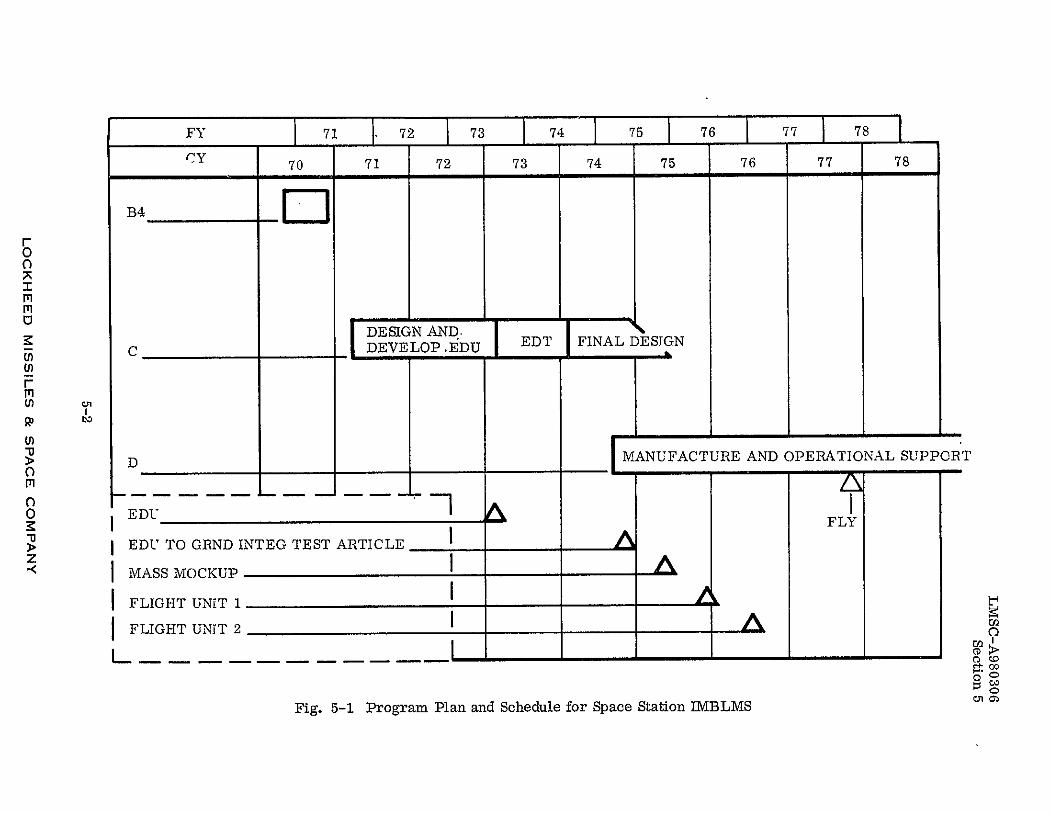
The preliminary NASA schedule for the, Space Station is presented in Fig. 5-1. In
Phase C, an EDU will be developed over a period of about 2 years. It will then under
go engineering development testing, after which the design will be updated and optimized
and the EDU upgraded for integration in the ground integration test article. Subsequently,
Phase D will begin. Two flight units will be manufactured - one for the flight vehicle
and one for the mission support vehicle.
5-1
LOCKHEED MISSILES & SPACE COMPANY
FY 1 72 73 74 75 76 u 77 78 CY 70 71 72 73 74 75 76 77 78
0I
'ii
DESIGN AND, Uc _C DEVELOP .EDU EDT FINAL DESIGN (rri) I"
>"D MANUFACTURE AND OPERATIONAL SUPPORT
oL -5
0K EDU -A
I FLY
T z EDU TO GRND INTEG TEST ARTICLE
M ASS MOCKUP
FLIGHT UNiT 1 I FLIGHT UNIT 2 o
Fig. 5-1 Program Plan and Schedule for Space Station IMBLMS 010)

5p61U7 vc) S77 $