Integrated Liquid Metal Elastomers for Flexible Electronics
29
1 Integrated Liquid Metal Elastomers for Flexible Electronics Undergraduate Thesis By Katie Frost Undergraduate Program in Mechanical Engineering The Ohio State University November 2020 Thesis Committee: Dr. Ryan L. Harne, Advisor Dr. Rebecca Dupaix
Transcript of Integrated Liquid Metal Elastomers for Flexible Electronics
1
Integrated Liquid Metal Elastomers for Flexible Electronics
Undergraduate Thesis
By
Katie Frost
Undergraduate Program in Mechanical Engineering
The Ohio State University
November 2020
Thesis Committee:
Dr. Ryan L. Harne, Advisor
Dr. Rebecca Dupaix

2
Copyright by
Katie Frost
2020

3
ABSTRACT
Emerging applications for conformable wearable devices and soft robotics create a need for flexible and
durable electronic materials. Non-toxic, liquid metals such as Gallium Indium provide remarkable
conformability without conductivity change when subjected to stress. Yet, advancements in developing
flexible materials that contain liquid metal focus primarily on development of liquid metal composites
rather than on an integration of liquid metal with elastomeric substrates. The goal of this research is to
experimentally characterize optimal elastomer-liquid metal material combination, substrate geometry, and
liquid metal particle size to create mechanically robust and flexible, conductive materials. The research will
create these materials by parametric fabrication and characterization processes. The research efforts include
mold design, 3D printing, sonication, casting, and evaluation of the conductivity of liquid metal-based
elastomers. It is determined that optimizing EGaIn for the use in conductive elastomeric materials requires
decreasing particle size through sonication, as well as the use of a strong acid or base to assist with
preventing oxidation This research will create new concepts for future electronics packaging solutions and
soft robotic actuators via a new integration of elastomers, liquid metal, and material design.

4
ACKNOWLEDGEMENTS
I would like to thank my advisor, Professor Ryan Harne, for believing in my academic and research abilities,
and for the incredible support he provides my colleagues and me to pursue excellence in research.
I also want to thank Professor Rebecca Dupaix for her time and expertise as my defense committee member.
Finally, I would like to acknowledge support from OSU College of Engineering for the Undergraduate
Research Scholarship, the First Year Undergraduate Summer Research Scholarship, and the Women in
Engineering Scholarship.
All related experiments in this research are conducted in the Laboratory of Sound and Vibration Research
(LSVR) that is directed by Dr. Harne.

5
TABLE OF CONTENTS
1 INTRODUCTION ................................................................................................................................. 8
1.1 Background and Previous Research ............................................................................................. 8
1.2 New contributions from this research ........................................................................................ 10
1.3 Research goal ............................................................................................................................. 10
1.4 Overview of thesis ...................................................................................................................... 10
2 METHODOLOGY .............................................................................................................................. 11
2.1 Strain-insensitivity of liquid metals ........................................................................................... 11
2.2 Oxidation .................................................................................................................................... 11
2.3 Sonication ................................................................................................................................... 12
2.4 Specimen fabrication .................................................................................................................. 13
2.5 Experimental setup ..................................................................................................................... 15
3 RESULTS AND DISCUSSION .......................................................................................................... 18
3.1 Qualitative evaluation results ..................................................................................................... 18
3.2 Load cell results ......................................................................................................................... 21
4 CONCLUSIONS ................................................................................................................................. 22
References ................................................................................................................................................... 23
5 APPENDIX ......................................................................................................................................... 27
5.1 Sample MATLAB code for data acquisition with load cell ....................................................... 27
6
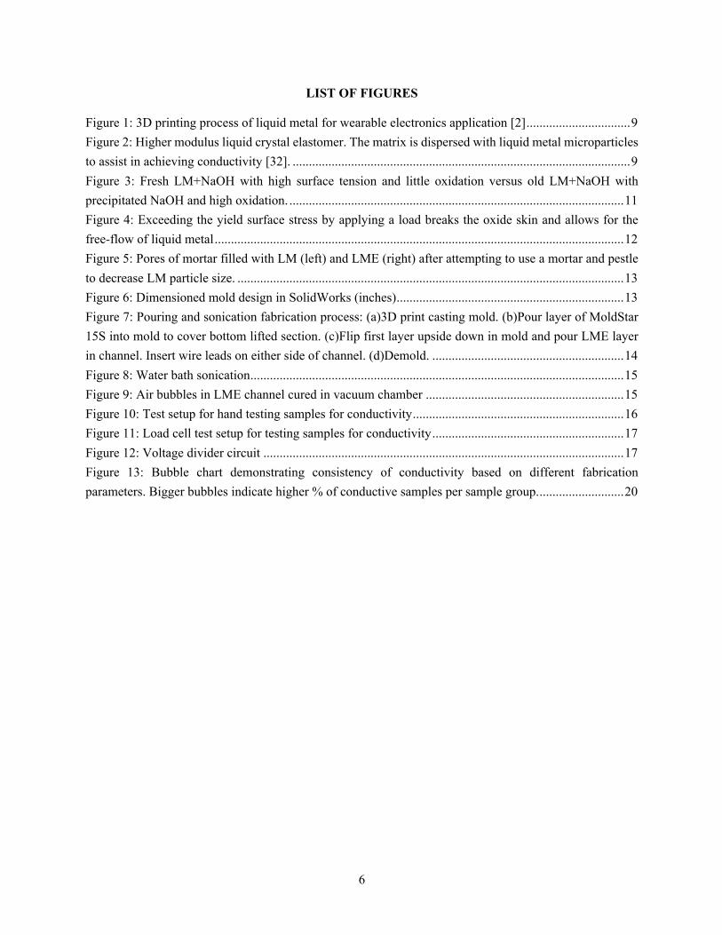
LIST OF FIGURES
Figure 1: 3D printing process of liquid metal for wearable electronics application [2] ................................ 9 Figure 2: Higher modulus liquid crystal elastomer. The matrix is dispersed with liquid metal microparticles to assist in achieving conductivity [32]. ........................................................................................................ 9 Figure 3: Fresh LM+NaOH with high surface tension and little oxidation versus old LM+NaOH with precipitated NaOH and high oxidation. ....................................................................................................... 11 Figure 4: Exceeding the yield surface stress by applying a load breaks the oxide skin and allows for the free-flow of liquid metal .............................................................................................................................. 12 Figure 5: Pores of mortar filled with LM (left) and LME (right) after attempting to use a mortar and pestle to decrease LM particle size. ....................................................................................................................... 13 Figure 6: Dimensioned mold design in SolidWorks (inches) ...................................................................... 13 Figure 7: Pouring and sonication fabrication process: (a)3D print casting mold. (b)Pour layer of MoldStar 15S into mold to cover bottom lifted section. (c)Flip first layer upside down in mold and pour LME layer in channel. Insert wire leads on either side of channel. (d)Demold. ........................................................... 14 Figure 8: Water bath sonication ................................................................................................................... 15 Figure 9: Air bubbles in LME channel cured in vacuum chamber ............................................................. 15 Figure 10: Test setup for hand testing samples for conductivity ................................................................. 16 Figure 11: Load cell test setup for testing samples for conductivity ........................................................... 17 Figure 12: Voltage divider circuit ............................................................................................................... 17 Figure 13: Bubble chart demonstrating consistency of conductivity based on different fabrication parameters. Bigger bubbles indicate higher % of conductive samples per sample group. .......................... 20

7
LIST OF TABLES Table 1: Properties of Eutectic Gallium Indium [3] [4] ................................................................................ 8 Table 2: Summary of hand-testing results based on fabrication process changes ....................................... 18
8
1 INTRODUCTION
1.1 Background and Previous Research
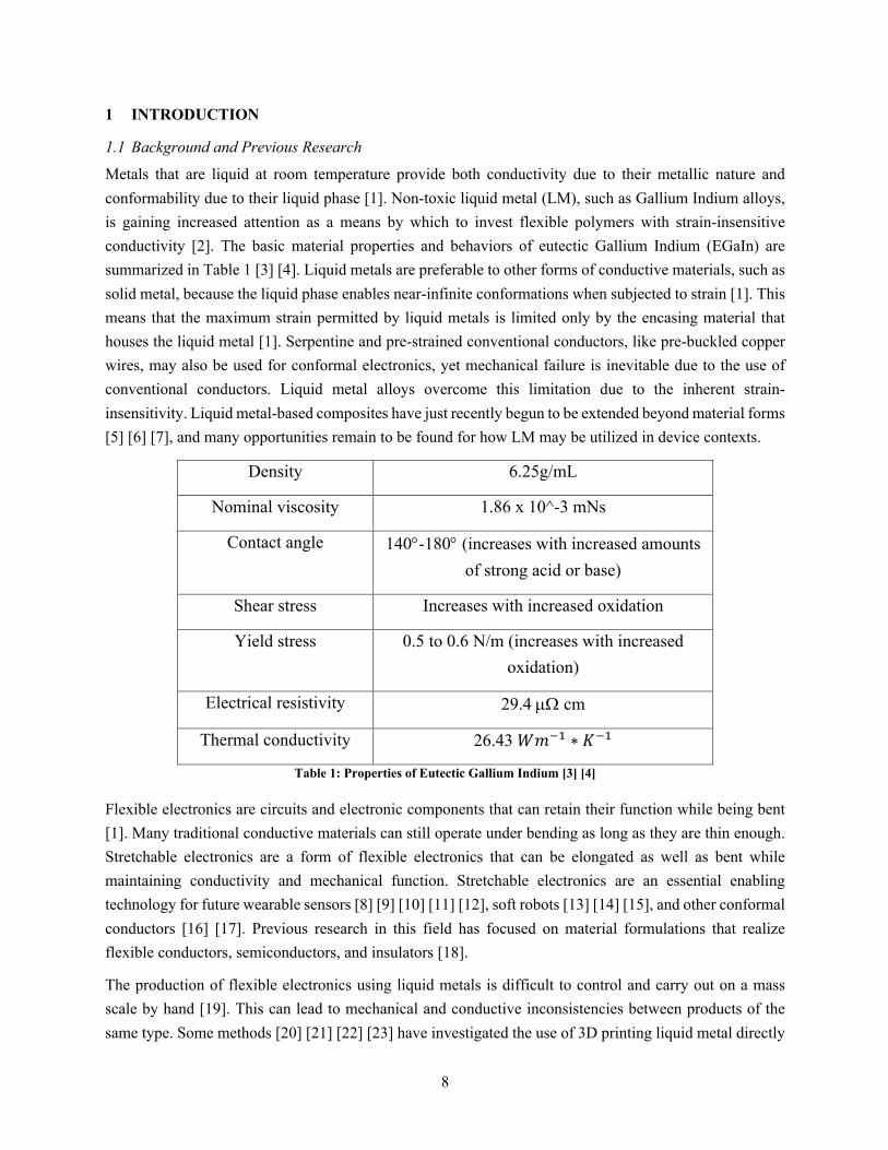
Metals that are liquid at room temperature provide both conductivity due to their metallic nature and conformability due to their liquid phase [1]. Non-toxic liquid metal (LM), such as Gallium Indium alloys, is gaining increased attention as a means by which to invest flexible polymers with strain-insensitive conductivity [2]. The basic material properties and behaviors of eutectic Gallium Indium (EGaIn) are summarized in Table 1 [3] [4]. Liquid metals are preferable to other forms of conductive materials, such as solid metal, because the liquid phase enables near-infinite conformations when subjected to strain [1]. This means that the maximum strain permitted by liquid metals is limited only by the encasing material that houses the liquid metal [1]. Serpentine and pre-strained conventional conductors, like pre-buckled copper wires, may also be used for conformal electronics, yet mechanical failure is inevitable due to the use of conventional conductors. Liquid metal alloys overcome this limitation due to the inherent strain-insensitivity. Liquid metal-based composites have just recently begun to be extended beyond material forms [5] [6] [7], and many opportunities remain to be found for how LM may be utilized in device contexts.
Density 6.25g/mL
Nominal viscosity 1.86 x 10^-3 mNs
Contact angle 140°-180° (increases with increased amounts of strong acid or base)
Shear stress Increases with increased oxidation
Yield stress 0.5 to 0.6 N/m (increases with increased oxidation)
Electrical resistivity 29.4 µW cm
Thermal conductivity 26.43 𝑊𝑚#$ ∗ 𝐾#$
Table 1: Properties of Eutectic Gallium Indium [3] [4]
Flexible electronics are circuits and electronic components that can retain their function while being bent [1]. Many traditional conductive materials can still operate under bending as long as they are thin enough. Stretchable electronics are a form of flexible electronics that can be elongated as well as bent while maintaining conductivity and mechanical function. Stretchable electronics are an essential enabling technology for future wearable sensors [8] [9] [10] [11] [12], soft robots [13] [14] [15], and other conformal conductors [16] [17]. Previous research in this field has focused on material formulations that realize flexible conductors, semiconductors, and insulators [18].
The production of flexible electronics using liquid metals is difficult to control and carry out on a mass scale by hand [19]. This can lead to mechanical and conductive inconsistencies between products of the same type. Some methods [20] [21] [22] [23] have investigated the use of 3D printing liquid metal directly

9
onto stretchable materials, such as in Figure 1 [2], as well as using vacuum-controlled suction or sprays to place individual LM droplets into place for circuitry [24] [25]. Others have used liquid metal channels between layers of elastomer [26] or used carefully placed carbon nanotubes [27] [28].
Figure 1: 3D printing process of liquid metal for wearable electronics application [2]
These methods have proven to be successful but only on the microscale due to the lower elastic modulus of materials used [29]. Combining liquid metal with elastomer by mixing the two liquids before curing the elastomer creates a liquid metal elastomer (LME) [30]. This results in one cohesive, conductive metamaterial that does not significantly degrade the elastic compliance, stretchability, or breakdown strength of the elastomer [30]. Recent successes in this area include LME films made with polydimethylsiloxane (PDMS) and galinstan and mixed with a mortar and pestle [31]. The samples became conductive when a localized compressive force tore the elastomer walls surrounding the liquid metal particles, forming a continuous network of liquid metal [4]. Recent progress has been made through the use of liquid crystal elastomer (LCE) matrices such as in Figure 2 [32], but a formulation of LME suitable higher modulus metamaterial has not yet been achieved.
Figure 2: Higher modulus liquid crystal elastomer. The matrix is dispersed with liquid metal microparticles to assist in
achieving conductivity [32].
10
1.2 New contributions from this research
This research provides a new methodology for creating reversibly conductive elastomeric materials through the use of sonication that allow for up to 440% elongation. This research provides a fast, simple methodology for creating conductive, higher modulus LME that is more mechanically robust than elastomer samples containing pure liquid metal. Using a method of molding and 3D casting with polymer and liquid metal combinations could potentially create more consistent flexible electronic devices.
1.3 Research goal
Through a parametric design process and experimental validations, the goal of this research is to study the elastomer-liquid metal material combination, substrate geometry, and liquid metal particle size that are optimal for creating flexible, conductive materials.
1.4 Overview of thesis
This thesis is organized as follows. Chapter 2 introduces the concepts of oxidation and sonication and discusses the methodology for creating and testing LME samples. Chapter 3 analyzes the results of the testing for conductivity, both through hand testing and load cell testing. Finally, Chapter 4 summarizes the findings and highlights optimal methods for creating samples, as well as recommendations for future work.
11
2 METHODOLOGY
This research includes mold design, 3D printing, sonication, casting, and evaluation of the conductivity of liquid metal-based elastomers. While conductive, liquid metals are favorable over traditional mechanical conductors because of their inherent strain-insensitivity, the oxide layer that may form on the surface of LM acts as an insulator. Breaking this layer allows the liquid to achieve conductivity and flow. Thus, Chapter 2 will introduce the concepts of formation of oxide layers and the importance of strong acids or bases in preventing oxidation and will then describe the importance of sonication in decreasing particle size. Subsequently, specimen fabrications and experimental testing setup will be described.
2.1 Strain-insensitivity of liquid metals
The liquid phase of metals, such as eutectic Gallium Indium at room temperature, enables near-infinite conformations when subjected to strain. This allows for electronic applications in cases in which traditional mechanical options would not be feasible. EGaIn has certain limitations for device contexts, such as oxidation [33], which must be overcome in order for use in practical electronics applications. Additionally, the use of liquid metal for electrical conductivity requires a continuously connected path of metal particles [18]. The use of sonication aids in both the mixing of LM with other liquids [31] and decreasing particle size [34] to improve conductivity.
2.2 Oxidation
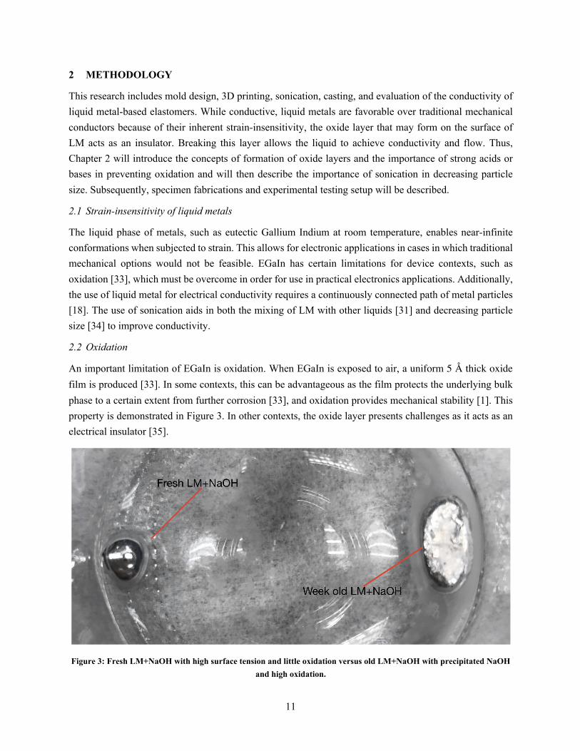
An important limitation of EGaIn is oxidation. When EGaIn is exposed to air, a uniform 5 Å thick oxide film is produced [33]. In some contexts, this can be advantageous as the film protects the underlying bulk phase to a certain extent from further corrosion [33], and oxidation provides mechanical stability [1]. This property is demonstrated in Figure 3. In other contexts, the oxide layer presents challenges as it acts as an electrical insulator [35].
Figure 3: Fresh LM+NaOH with high surface tension and little oxidation versus old LM+NaOH with precipitated NaOH
and high oxidation.

12
When trying to achieve conductivity this film must be broken to allow for the free-flow of liquid metal. Below the critical yield surface stress (around 0.5 to 0.6 N/m), the skin is elastic and stable, and above the critical yield stress, the skin ruptures and metal flows [36]. This property is demonstrated in Figure 4. The oxide skin is amphoteric and can be removed at pH <3 or pH >10 [36]. Thus, the presence of a strong base, such as sodium hydroxide, NaOH, can remove the oxide skin through a reduction process. Exposure of EGaIn to NaOH also slows the onset of further oxidation, resulting in improved conductivity for longer functional times. The full oxide layer does not form at once, but rather develops over the course of several days [37] It is also important to note that mechanical measurements on oxidizing films are both strain-history and time dependent [35].
Figure 4: Exceeding the yield surface stress by applying a load breaks the oxide skin and allows for the free-flow of liquid
metal
2.3 Sonication
Water bath sonication involves agitation of a liquid sample with ultrasound waves. The sound waves cause two distinct bubble behaviors in the water bath which affect the sample: stable and transient [38]. Stable bubbles are generated when peak sound pressure in the rarefaction cycle is not strong enough to force the bubble to expand its collapse radius and normally oscillate for a time scale of thousands of acoustic cycles [38]. Transient bubbles occur when acoustic pressure exerts cavity expansion to its resonant radius in half or several acoustic cycles, then collapse rapidly [38]. These bubbles are much shorter than stable bubbles and cause much greater disruption in material due to extremely high local temperatures of about 5000°C [39] and pressures greater than 10 GPa [40] in the moment of bubble implosion. These bubbles produce shock waves which result in high-velocity interparticle collisions [41], causing the liquid metal particles to break down in size as a result. The most significant effects of sonication on particle size are seen at the very beginning of sonication [38]. Sonication results in both a uniform mixing of materials and a decrease in particle size over time [42] [34].
One methodology that was attempted during this research that ultimately failed was using a mortar and pestle to decrease the size of the LM particles. While there was a visible decrease in particle size of the EGaIn, the adhesive nature of the oxide layer caused the particles to fill the porous surface of the mortar,

13
making it impossible to recollect the LM after mixing. The dispersion of the LM particles in the mortar can be seen in Figure 5.
Figure 5: Pores of mortar filled with LM (left) and LME (right) after attempting to use a mortar and pestle to decrease
LM particle size.
2.4 Specimen fabrication
The optimal geometry for testing conductivity, found in Figure 6, was determined to be a thin rectangular prism with an enclosed straight channel of LME. Thinner film-like samples did not adequately encase the liquid metal, while thicker samples required too large of loads to apply by hand. Having a fully enclosed LME channel assisted in keeping the liquid metal inside the specimen when large loads are applied.
Figure 6: Dimensioned mold design in SolidWorks (inches)

14
The first step of sample fabrication was to 3D print the mold which was the negative of the desired geometry. These molds were modeled in SolidWorks and printed on a FlashForge Creator Pro 3D printer. The second step was to pour a layer of Smooth-On MoldStar 15S in the mold. MoldStar 15S is a 15A durometer silicone rubber that allows for up to 440% elongation. This layer cured for four hours and can be seen in Figure 7.
Figure 7: Pouring and sonication fabrication process: (a)3D print casting mold. (b)Pour layer of MoldStar 15S into mold
to cover bottom lifted section. (c)Flip first layer upside down in mold and pour LME layer in channel. Insert wire leads on either side of channel. (d)Demold.
The third step was to flip the cured elastomer upside down in the mold and pour the uncured LME into the channel. To make the LME, EGaIn was removed from its container with a syringe and was weighed on a laboratory scale. Given the EGaIn density of 6.25 g/mL the volume was calculated. An equal volume of 0.1 M concentration NaOH was added to the EGaIn. These two liquids were then sonicated in a small glass beaker in a Branson M1800 Ultrasonic Mixer, seen in Figure 8, before being added to an equal weight portion of MoldStar 15S. The sonicated liquids and equal weight-part elastomer were mixed in a separate container by hand before being poured in the channels. This layer cured for four hours and can be seen in Figure 7. The final step involved putting copper wires into either side of the cured channel of LME and then pouring the final layer of elastomer on top. This layer cured for four hours before being demolded for testing and can be seen in Figure 7. The final dimensions of the samples were 1.18in long by 0.30in wide by 0.39in deep.

15
Figure 8: Water bath sonication
Curing the LME layer inside a vacuum chamber was tested to help better seal the samples from air for the purpose of preventing oxidation. Unfortunately, the LME cured with air bubbles which caused gaps in the channel as seen in Figure 9, and ultimately lead to failed conductivity tests.
Figure 9: Air bubbles in LME channel cured in vacuum chamber
2.5 Experimental setup
The fabrication process took many months of trial and error before being optimized. In order to save time and resources, only hand tests were performed on these initial samples to determine if they were conductive.

16
For the hand test a multimeter with two alligator-clip leads was attached to the wires on either side of the sample to evaluate the resistance through the sample. Next, an approximately 30N load was applied with a finger to the middle of the sample, as seen in Figure 10. Each sample underwent this loading for about 3 seconds at a time for 1 minute.
Figure 10: Test setup for hand testing samples for conductivity
After the fabrication process was finalized, evaluation of mechanical and electrical properties was conducted in a mechanical test frame. These tests were carried out using a PCB Load and Torque Canister Load Cell, seen in Figure 11. The load cell has a 300lbf capacity and a cylindrical attachment was used to apply a point-load to the middle of the sample.

17
Figure 11: Load cell test setup for testing samples for conductivity
Alligator clips were attached to the sample lead wires and were placed in parallel with R1 in the voltage divider circuit seen in Figure 12. The output voltage of this circuit was read out using a MyDAQ data acquisition tool. The load cell was controlled through the program MTESTQuatro. The load cell compressed the sample 6mm at a set speed and then immediately returned to its starting position at the same speed. The voltage and load data were recorded with a MATLAB code found on page 27. The input and output voltages, as well as the resistance of the known resistor, were then used to calculate the resistivity of the sample. The resistivity was plotted against the strain on the sample based on the applied load in MATLAB.
Figure 12: Voltage divider circuit
18
3 RESULTS AND DISCUSSION
Chapter 3 summarizes the optimal fabrication process based on qualitative evaluation and then discusses future modifications that could be made to ensure effective results are obtained for the quantitative assessments in the mechanical load frame. From the experimental data, the results are analyzed to investigate the impact of sonication and addition of a base on the conductivity of liquid-metal elastomers.
3.1 Qualitative evaluation results
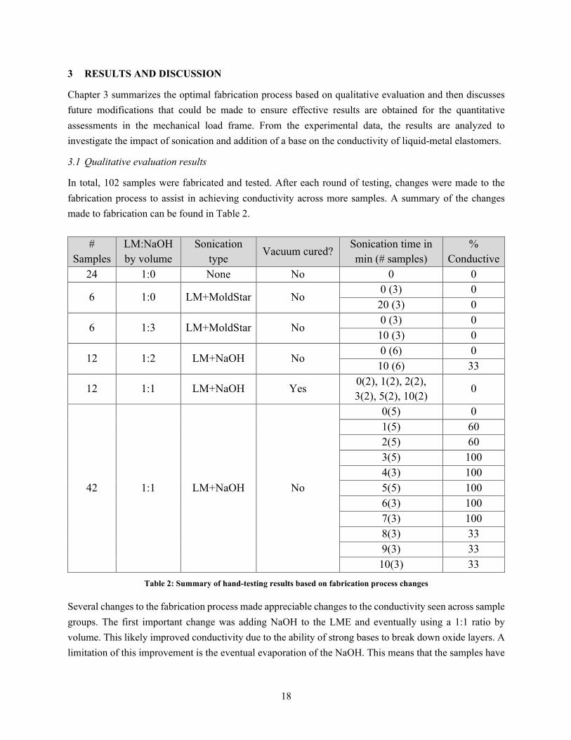
In total, 102 samples were fabricated and tested. After each round of testing, changes were made to the fabrication process to assist in achieving conductivity across more samples. A summary of the changes made to fabrication can be found in Table 2.
Table 2: Summary of hand-testing results based on fabrication process changes
Several changes to the fabrication process made appreciable changes to the conductivity seen across sample groups. The first important change was adding NaOH to the LME and eventually using a 1:1 ratio by volume. This likely improved conductivity due to the ability of strong bases to break down oxide layers. A limitation of this improvement is the eventual evaporation of the NaOH. This means that the samples have
# Samples
LM:NaOH by volume
Sonication type
Vacuum cured? Sonication time in min (# samples)
% Conductive
24 1:0 None No 0 0
6 1:0 LM+MoldStar No 0 (3) 0 20 (3) 0
6 1:3 LM+MoldStar No 0 (3) 0 10 (3) 0
12 1:2 LM+NaOH No 0 (6) 0 10 (6) 33
12 1:1 LM+NaOH Yes 0(2), 1(2), 2(2), 3(2), 5(2), 10(2)
0
42 1:1 LM+NaOH No
0(5) 0 1(5) 60 2(5) 60 3(5) 100 4(3) 100 5(5) 100 6(3) 100 7(3) 100 8(3) 33 9(3) 33 10(3) 33

19
a limited life in which they conduct successfully. Possible solutions to this could be found in vacuum-curing the LME layer earlier in the pot life to ensure that air bubbles are eliminated. This would make the sample more air-tight and would slow down the oxidation process. Storing the samples inside a vacuum chamber could also potentially help with this.
Partnered with this change was the switch in sonication type from LM and elastomer to LM and NaOH. Sonicating the LM and elastomer caused the elastomer to cure too quickly due to the high temperatures induced during sonication which is a catalyst to the cross-link process of the silicone rubber. This resulted in a gum-like texture that did not allow the liquid metal to spread evenly throughout the elastomer before it cured. Using a chilled water bath in the sonicator could help in slowing down the curing process some. Sonicating the liquid metal with just the NaOH before hand-mixing the uncured elastomer likely helped to further break down the oxide layer, decreased particle size to an optimal size, and ensured that liquid metal was evenly dispersed throughout the elastomer to help create a continuous path of LM particles.
Another important adjustment was changing the sonication time from half of the samples for 0 minutes and half for 10 minutes to increments of 1 minute from 0 to 10 minutes. This demonstrated that the optimal time for sonication was between 3-7 minutes. This time range likely broke down the LM particles to a small enough size to allow for a continuous path of particles to be created within the elastomer.
Due to the many different factors adjusted in the fabrication process, the results are best visualized in groupings based on percentage of conductive samples. Figure 13 contains a bubble chart of the data grouped based on the parameters of the fabrication process that were changed. Each round is represented by a different color bubble. Bigger bubbles denote a higher percentage of conductive samples. This chart demonstrates that the optimal fabrication process for creating conductive elastomeric materials involves sonicating a LM:NaOH volume ratio of 1:1 for between 3-7 minutes without vacuum curing the LME layer.

20
Figure 13: Bubble chart demonstrating consistency of conductivity based on different fabrication parameters. Bigger bubbles indicate higher % of conductive samples per sample group.

21
Generally, liquid metal particles in aqueous solution such as NaOH are not stable since gallium tends to react with water and oxygen to form gallium oxide monohydroxide, and the suspension will precipitate [4]. The presence of a hydrophilic polymer such as MoldStar 15S is able to stabilize the LM particles for a few days [4]. This stabilization and delay in oxidation are likely factors which allowed the samples to conduct during hand testing but not successfully days later during load frame testing.
Both the size and loading of LM particles within the elastomer affect the properties of the resulting liquid metal soft composite [4]. The use of sonication allowed for the adjustment of LM particle size. While it is also possible to break the liquid metal into particles in situ by mixing liquid metal with elastomer pre‐polymer, more success was found by preparing the particles first, followed by mixing with an elastomer precursor prior to curing the composite. This process broke down the LM particle size more which allowed for a much more even dispersion throughout the elastomer. Due to the 1:1 LM to elastomer ratio by weight, there was about 6 times more LM than elastomer by volume. This ultimately resulted in many more continuous, conductive pathways being possible without needing the elastomer to tear. This concept has been proven in rheological and X-ray tomography studies that show that decreasing the size of the liquid metal will increase the viscosity of the dispersion [43].
3.2 Load cell results
Due to the strain history and time dependence of mechanical measurements on oxidizing films [35], it was found that load cell testing presented many challenges to measuring conductivity. Three rounds of testing were completed with 10 samples per round. Approximately two-thirds of the samples demonstrated conductivity under strain when tested by hand, but none of the samples demonstrated conductivity on the load cell. After one round of testing both the number of cycles and loading speeds were increased with no improvement in measurements.
There are several possible reasons as to why the load-cell tests were not successful. The first possibility is that the rate that the load was applied was too slow. Even when increased to 20mm/min, this rate was much slower compared to the rate of the hand tests which completely compressed the sample in about 1 second (approximately 360mm/min). If the rate was too slow it might not have broken the oxide layer as effectively and conductivity wouldn’t have been possible. The second possibility is that the samples were too old once the load-cell tests were carried out. There were typically several days between the LME layer being poured and the samples being tested; this is potentially enough time for the NaOH to evaporate. This evaporation of the liquid makes the base ineffective at preventing oxidation, and therefore could contribute to conductivity not being achieved. The third possibility is that the type of applied load was not ideal for achieving conductivity. It is possible that the area of the applied load needs to increase or decrease to create the strain needed. While a point-load is more ideal for breaking the oxide layer, a more spread-out load is ideal for creating greater strain across the entire sample.

22
4 CONCLUSIONS
Based on the findings, optimizing EGaIn for the use in conductive elastomeric materials requires decreasing
particle size through sonication, as well as the use of a strong acid or base to assist with preventing
oxidation. There are many avenues for continuing and improving upon this research. Adjusting the vacuum
curing process could better seal the samples and prevent the NaOH from evaporating as quickly to increase
overall sample life. Adjusting substrate geometry could lead to opportunities for investigating shock and
vibration mitigation capabilities of these materials in device contexts. Finally, adjusting the load-cell testing
process would allow for a more detailed understanding in the relationship between sonication time and
conductivity of these samples. This process could change through the number of cycles, the applied load,
the speed at which the load is applied, and the type of point-load that is used.

23
References
[1] M. Dickey, "Stretchable and soft electronics using liquid metals," Advanced Materials, vol. 29, p. 1606425, 2017.
[2] A. Valentine, T. Busbee, J. Boley, J. Raney, A. Chortos, A. Kotikian, J. Berrigan, M. Durstock and J. Lewis, "3D printing of soft electronics," Advanced Materials, vol. 29, p. 1703817, 2017.
[3] Q. Xu, N. Oudalov, Q. Guo, H. Jaeger and E. Brown, "Effect of oxidation on the mechanical properties of liquid gallium and eutectic gallium-indium," arXiv Physics, 2012.
[4] Y. Lin, J. Genzer and M. Dickey, "Attributes, fabrication, and applications of gallium-based liquid metal particles," Advanced Science, vol. 7, 2020.
[5] M. Malakooti, N. Kazem, J. Yan, C. Pan, E. Markvicka, K. Matyjaszewski and C. Majidi, "Liquid metal supercooling for low-temperature thermoelectric wearables," Advanced functional materials, vol. 29, p. 1906098, 2019.
[6] X. Huang, K. Kumar, M. Jawed, Z. Ye and C. Majidi, "Soft electrically actuated quadruped (SEAQ)-integrating a flex circuit board and elastomeric limbs for versatile mobility," IEEE Robotics and Automation Letters, 2019.
[7] C. Majidi, "Soft circuits that heal underwater," Nature Electronics, vol. 2, 2019.
[8] C. Pang, G. Lee, T. Kim, S. Kim, H. Kim, S. Ahn and K. Suh, "A flexible and highly sensitive strain-gauge sensor using reversible interlocking of nanofibers," Nature Materials, vol. 1, pp. 795-801, 2012.
[9] C. Lee, Y. Ma, K. Jang, A. Banks, T. Pan, X. Feng, J. Kim, D. Kang, M. Raj, B. McGrane, B. Morey, X. Wang, R. Ghaffari, Y. Huang and J. Rogers, "Soft core/shell packages for stretchable electronics," Advanced Functional Materials, vol. 25, pp. 3698-3704, 2015.
[10] W. Gao, S. Emaminejad, H. Nyein, S. Challa, K. Chen, A. Peck, H. Fahad, H. Ota, H. Shiraki, D. Kiriya, D. Lien, G. Brooks, R. Davis and A. Javey, "Fully integrated wearable sensor arrays for multiplexed in situ perspiration analysis," Nature, vol. 529, pp. 509-514, 2016.
[11] D. Kim, N. Lu, R. Ma, Y. Kim, R. Kim, S. Wang, J. Wu, S. Won, H. Tao, A. Islam, K. Yu, T. Kim, R. Chowdhury, M. Ying, L. Xu, M. Li, H. Chung, H. Keum, M. McCormick, P. Liu, Y. Zhang, F. Omenetto, Y. Huang, T. Coleman and J. Rogers, "Epidermal electronics," Science, vol. 333, pp. 838-843, 2011.

24
[12] Y. Yang, N. Sun, Z. Wen, P. Cheng, H. Zheng, H. Shao, Y. Xia, C. Chen, H. Lan, X. Xie, C. Zhou, J. Zhou, Z. Sun and S. Lee, "Liquid-metal-based super-stretchable and structure-designable triboelectric nanogenerator for wearable electronics," ACS Nano, vol. 12, pp. 2027-2034, 2018.
[13] R. Martinez, J. Branch, C. Fish, L. Jin, R. Shepherd, R. Nunes, Z. Suo and G. Whitesides, "Robotic tentavles with three-dimensional mobility based on flexible elastomers," Advanced Materials, vol. 25, pp. 205-212, 2013.
[14] M. Wehner, R. Truby, D. Fitzgerald, B. Mosadegh, G. Whitesides, J. Lewis and R. Wood, "An integrated design and fabrication strategy for entirely soft, autonomous robots," Nature, vol. 536, pp. 451-455, 2016.
[15] A. Marchese, C. Onal and D. Rus, "Autonomous soft robotic fish capable of escape maneuvers using fluidic elastomer actuators," Soft Robotics, vol. 1, p. 75, 2014.
[16] H. Ko, M. Stoykovich, J. Song, V. Malyarchuk, W. Choi, C. Yu, J. GeddesIii, J. Xiao, S. Wang, Y. Huang and J. Rogers, "A hemispherical electronic eye camera based on compressible silicon optoelectronics," Nature, vol. 454, pp. 748-753, 2008.
[17] O. Graudejus, B. Morrison, C. Goletiani, Z. Yu and S. Wagner, "Encapsulating elastically stretchable neural interfaces: yield, resolution, and recording/stimulation of neural activity," Advanced Functional Materials, vol. 22, pp. 640-651, 2012.
[18] J. Rogers, T. Someya and Y. Huang, "Materials and mechanics for stretchable electronics," Science, vol. 327, pp. 1603-1607, 2010.
[19] S. Kumar, B. Benicewicz, R. Vaia and K. Winey, "50th anniversary perspective: are polymer nanocomposites practical for applications?," Macromolecules, vol. 50, pp. 714-731, 2017.
[20] A. Frutiger, J. Muth, D. Vogt, Y. Mengüç, A. Campo, A. Valentine, C. Walsh and J. Lewis, "Capacitive soft strain sensors via multicore-shell fiber printing," Advanced Materials, vol. 27, pp. 2440-2446, 2015.
[21] J. Muth, D. Vogt, R. Truby, Y. Mengüç, D. Kolesky, R. Wood and J. Lewis, "Embedded 3D printing of strain sensors within highly stretchable elastomers," Advanced Materials, vol. 26, pp. 6307-6312, 2014.
[22] T. Someya, Y. Kato, T. Sekitani, S. Iba, Y. Noguchi, Y. Murase, H. Kawaguchi and T. Sakurai, "Conformal, flexible, large-area networks of pressure and thermal sensors with organic transistor active matrices," in National Academy of Sciences, USA, 2005.

25
[23] T. Someya, T. Sekitani, S. Iba, Y. Kato, H. Kawaguchi and T. Sakurai, "A large-area, flexible pressure sensor matrix with organic field-effect transistors for artificial skin applications," in National Academy of Sciences, USA, 2004.
[24] K. Takei, T. Takahashi, J. Ho, H. Ko, A. Gillies, P. Leu, R. Fearing and A. Javey, "Nanowire active matrix circuitry for low-voltage macroscale artificial skin," Nature Materials, vol. 9, pp. 351-366, 2010.
[25] D. Lipomi, M. Vosgueritchian, B. Tee, S. Hellstrom, J. Lee, C. Fox and Z. Bao, "Skin-like pressure and strain sensors based on trasnparent elastic films of carbon nanotubes," Nature Nanotechnology, vol. 6, pp. 788-792, 2011.
[26] S. Xu, Y. Zhang, L. Jia, K. Mathewson, K. Jang, J. Kim, H. Fu, X. Huang, P. Chava, R. Wang, S. Bhole, L. Wang, Y. Na, Y. Guan, M. Flavin, Z. Han, Y. Huang and J. A. Rogers, "Soft microfluidic assemblies of sensors, circuits, and radios for the skin," Science, vol. 344, pp. 70-74, 2014.
[27] T. Yamada, Y. Hayamizu, Y. Yamamoto, Y. Yomogida, A. Izadi-Najafabadi, D. Futaba and K. Hata, "A stretchable carbon nanotube strain sensor for human-motion detection," National Nanotechnology, vol. 6, pp. 296-301, 2011.
[28] J. Kim, M. Lee, H. Shim, R. Ghaffari, H. Cho, D. Son, Y. Jung, M. Soh, C. Choi, S. Jung, K. Chu, D. Jeon, S. Lee, J. Kim, S. Choi, T. Hyeon and D. Kim, "Stretchable silicon nanoribbon electronics for skin prosthesis," Nature Communications, vol. 5, p. 5747, 2014.
[29] C. Thrasher, Z. Farrell, N. Morris, C. Willey and C. Tabo, "Mechanoresponsive polymerized liquid metal networks," Advanced Materials, p. 1903864, 2019.
[30] C. Pan, E. Markvicka, M. Malakooti, J. Yan, L. Hu, K. Matyjaszewski and C. Majidi, "A liquid-metal-elastomer nanocomposite for stretchable dielectric materials," Advanced Materials, vol. 31, 2019.
[31] A. Fassler and C. Majidi, "Liquid phase metal inclusions for a conductive polymer composite," Advanced Materials, vol. 27, pp. 1928-1932, 2015.
[32] M. Ford, C. Ambulo, T. Kent, E. Markvicka, C. Pan, J. Malen, T. Ware and C. Majidi, "A multifunctional shape-morphing elastomer with liquid metal inclusions," in National Academy of Sciences, USA, 2019.
[33] H. Tostmann, E. DiMasi, P. Pershan, B. Ocko, O. Shpyrko and M. Deutsch, "Surface structure of liquid metals and the effect of capillary waves: x-ray studies on liquid indium," The American Physical Society, vol. 59, pp. 783-791, 1999.

26
[34] A. Ciesielski and P. Samori, "Graphene via sonication assisted liquid-phase exfoliation," Royal Society of Chemistry, vol. 43, pp. 381-398, 2014.
[35] R. Larsen, M. Dickey, G. Whitesides and D. Weitz, "Viscoelastic properties of oxide-coated liquid metals," The Society of Rheology , vol. 53, pp. 1305-1326, 2009.
[36] M. Dickey, "Emerging applications of liquid metals featuring surface oxides," ACS Applied Materials and Interfaces, vol. 21, pp. 18369-18379, 2014.
[37] L. Cademartiri, M. Thuo, C. Nijhuis, W. Reus, S. Tricard, J. Barber, R. Sodhi, P. Brodersen, C. Kim, R. Chiechi and G. Whitesides, "The electrical resistance of AgTS-S(CH2)n-1CH3//Ga2O3/EGaIn tunneling junctions," Journal of Physical Chemistry, vol. 116, p. 10848, 2012.
[38] K. Show, T. Mao and D. Lee, "Optimization of sludge disruption by sonication," Science Direct: Water Research, vol. 41, pp. 4741-4747, 2007.
[39] J. Laborde, C. Bouver, J. Caltagirone and A. Gerard, "Acoustic bubble cavitation at low frequencies," Science Direct: Ultrasonics, vol. 36, pp. 589-594, 1998.
[40] U. Neis, K. Nickel and A. Tiehm, "Enhancement of anaerobic sludge digestion by ultrasonic disintegration," Science Direct: Water Science Technology, vol. 42, pp. 73-80, 2000.
[41] K. Suslick, "Sonochemistry," Science, vol. 247, p. 1439, 1990.
[42] J. Hohman, M. Kim, G. Wadsworth, H. Bednar, J. Jiang and M. LeThai, "Directing substrate morphology via self-assembly: ligand-mediated scission of gallium-indium microspheres to the nanoscale," Nano Letters, vol. 11, p. 5104, 2011.
[43] A. Koh, J. Sietins, G. Slipher and R. Mrozek, "Deformable liquid metal polymer composites with tunable electronic and mechanical properties," Journal of Materials Research, vol. 33, pp. 2443-2453, 2018.
[44] J. Yan, M. Malakooti, Z. Lu, Z. Wang, N. Kazem, C. Pan, M. Bockstaller and K. Matyjaszewski, "Solution processable liquid metal nanodroplets by surface-initiated atom transfer radical polymerization," Nature Nanotechnology, vol. 14, pp. 684-690, 2019.
[45] M. Bartlett, A. Fassler, N. Kazem, E. Markvicka, P. Mandal and C. Majidi, "Stretchable, high-k dielectric elastomers through liquid-metal inclusions," Advanced Materials, vol. 28, pp. 3726-3731, 2016.

27
5 APPENDIX
5.1 Sample MATLAB code for data acquisition with load cell
clear all warning off % preset post-processing built for load-frame experiments using load cell % and displacement transducers %% acquire data? dataacquire=1; % yes for acquire %% experimental setup parameters d.test_name='load_frame'; % type of excitation delivered to beam d.load_rate=20; % [mm/min] rate of load frame displacement during experiment %% test specimen name, parameters d.specimen='test_run_1 with fixed resistance'; % specimen name, or no_specimen if none d.thickness=8e-3; %specimen undeformed thickness [m] %% data acquisition setup parameters d.fs=4; % sampling frequency [Hz] d.wind=@hann; % window type for averages d.seconds=125; % [s] seconds of data acquisition d.filter_data_lo=1; % [Hz] of low pass cut off frequency %% filename for save d structure c=clock; % grab the time-stamp, eliminates possibility of data overwrite d.filename=[num2str(c(1)) '_' num2str(c(2),'%02.0f') '_' num2str(c(3),'%02.0f') '_' num2str(c(4),'%02.0f') '_' num2str(c(5),'%02.0f') '_' num2str(c(6),'%02.0f') '.mat']; saveon=1; % save the data? 0 = no |1 = data %% sensor sensitivity d.sensor{1}='PCB_110204A_SN969_load_cell_and_signal_conditioner_8162011A_SN1273'; d.ch_sens(1)= 1334/10; % N/V d.sensor{2}='Micro_epsilon_optoncdt-ILD1700-200_laser_displacement_sensor_SN1503086'; d.ch_sens(2)=200/10; % mm/V d.sensor{3}='Voltage divider output'; d.ch_sens(3)=1; % V/V %% mean sensor values [V] for each channel, to be subtracted from the input before sensitivity to [units] d.data_mean(1)=0.470316213651242; % d.data_mean(2)=3.274305330872914; % d.data_mean(3)=0; % %% if for data acquisition if dataacquire==1 % 1=yes for acquire %% identify connected devices devices=daq.getDevices;

28
% once obtained, ensure using correct device name in below session and acquire lines %% acquire data s=daq.createSession('ni'); s.addAnalogInputChannel('Dev1',0,'Voltage'); % add input channels s.addAnalogInputChannel('Dev1',1,'Voltage'); % add input channels s.addAnalogInputChannel('Dev1',2,'Voltage'); % add input channels s.Rate=d.fs; % set output and measuring frequency [Hz] s.DurationInSeconds=d.seconds; % [s] duration of data acquisition [d.data,d.time_series]=s.startForeground; d.nn_chan=min(size(d.data)); end %% bandpass filter data clear ch_f d.nn_chan=min(size(d.data)); myfilt=designfilt('lowpassiir','filterorder',8,'passbandfrequency',d.filter_data_lo,'PassbandRipple',0.01,'samplerate',d.fs); % myfilt=designfilt('bandpassiir','filterorder',4,'HalfPowerFrequency1',d.filter_data_lo,'HalfPowerFrequency2',d.filter_data_hi,'samplerate',d.fs); %% assign filtered data % ch_f = filter(myfilt,d.ch_sens.*(d.data-d.data_mean)); ch_f(:,1) = filter(myfilt,d.ch_sens(1).*(d.data(:,1)-d.data(1,1))); ch_f(:,2) = filter(myfilt,d.ch_sens(2).*(d.data(:,2)-d.data(1,2))); ch_f(:,3) = filter(myfilt,d.ch_sens(3).*(d.data(:,3)-d.data(1,3))); d.data_filt=ch_f; % re-assign filtered data from local to structure variable %% plot colors=['r' 'g' 'b' 'c' 'm']; markers=['o' 's' 'd' 'v' '^']; color_plot=1; smooth_inc=11; smooth_inc_stiffness=11; trunc=10:4:round(1*length(d.time_series))-100; stiffness=gradient(smooth(d.data_filt(trunc,1),smooth_inc_stiffness))./gradient(smooth(1e-3*d.data_filt(trunc,2),smooth_inc_stiffness)); deformed_length=d.thickness-1e-3*d.data_filt(trunc,2); %[m] displacement=d.data_filt(trunc,2); %[mm] figure(71); clf; hold on; plot(smooth(1*(d.data_filt(trunc,2)),smooth_inc),smooth(-d.data_filt(trunc,1),smooth_inc),'color',colors(color_plot)); xlabel('displacement [mm]'); ylabel('force [N]'); box on; title([strrep(d.filename,'_','-')]); [1] [1] figure(73);

29
clf; hold on; plot(smooth((1+(1*d.data_filt(trunc,2)-1e3*d.thickness)/1e3/d.thickness),smooth_inc),smooth(-d.data_filt(trunc,1),smooth_inc),'color',colors(color_plot)); xlabel('strain [mm/mm]'); ylabel('force [N]'); box on title([strrep(d.filename,'_','-')]) resistance1=2*5./d.data_filt(trunc,3)-2; % resistance of measured sample figure(74); clf; hold on; % plot(smooth((1+(1*d.data_filt(trunc,2)-1e3*d.thickness)/1e3/d.thickness),smooth_inc),resistance1,'color',colors(color_plot)); plot(smooth((1+(1*d.data_filt(trunc,2)-1e3*d.thickness)/1e3/d.thickness),smooth_inc),d.data_filt(trunc,3),'color',colors(color_plot)); xlabel('strain [mm/mm]'); ylabel('resistance [Ohm]'); box on title([strrep(d.filename,'_','-')]) %% save data if saveon > 0 d.data_filt=[]; save(d.filename,'d'); end %%