Integrated Development Environment - FESBmarjan.fesb.hr/~tihana/Programiranje1/2.pdf · Visual...
26
2 Integrated Development Environment Objectives • To become familiar with the integrated development environment. • To be able to create a standard executable. • To be able to identify the controls in the toolbox. • To be able to understand the types of commands contained in the menus and the tool bar. • To be able to customize the form using properties. • To be able to customize the form using controls. • To be able to customize controls using properties. • To be able to save a project. • To be able to execute a simple program. • To understand the difference between design mode and run mode. Seeing is believing. Proverb Form ever follows function. Louis Henri Sullivan Intelligence . . . is the faculty of making artificial objects, especially tools to make tools. Henri-Louis Bergson Our life is frittered away by detail . . . Simplify, simplify. Henry Thoreau
-
Upload
phungnguyet -
Category
Documents
-
view
222 -
download
0
Transcript of Integrated Development Environment - FESBmarjan.fesb.hr/~tihana/Programiranje1/2.pdf · Visual...

2
Integrated Development Environment
Objectives
• To become familiar with the integrated development environment.
• To be able to create a standard executable.• To be able to identify the controls in the toolbox.• To be able to understand the types of commands
contained in the menus and the tool bar.• To be able to customize the form using properties.• To be able to customize the form using controls.• To be able to customize controls using properties.• To be able to save a project.• To be able to execute a simple program.• To understand the difference between design mode
and run mode.
Seeing is believing.
Proverb
Form ever follows function.
Louis Henri Sullivan
Intelligence . . . is the faculty of making artificial objects, especially tools to make tools.
Henri-Louis Bergson
Our life is frittered away by detail . . . Simplify, simplify.
Henry Thoreau
26 I
NTEGRATED
D
EVELOPMENT
E
NVIRONMENT
C
HAPTER
2
Outline
2.1 Introduction2.2 Integrated Development Environment Overview2.3
Project
Window2.4 Toolbox2.5
Form
Layout
Window2.6
Properties
Window2.7 Menu Bar and Tool Bar2.8 A Simple Program: Displaying a Line of Text
Summary • Terminology • Good Programming Practices • Self-Review Exercises • Answers to Self-Review Exercises • Exercises
2.1 Introduction
Visual Basic’s
Integrated Development Environment
(
IDE
) allows the programmer to cre-ate, run and debug Windows programs in one application (e.g., Visual Basic) without theneed to open additional programs (i.e., a program to create the program, a program that ex-ecutes the program, a program that debugs the program, etc.). In this chapter, we overviewthe Visual Basic IDE features and discuss how to create and execute a simple program.
2.2 Integrated Development Environment Overview
When Visual Basic is loaded, the
New
Project
dialog
shown in Fig. 2.1 is displayed. The
New
Project
dialog allows the programmer to choose what type of Visual Basic programto create.
Standard
EXE
, which is highlighted by default, allows the programmer to cre-ate a
standard executable
(i.e., a program that uses the most common Visual Basic fea-tures). We use
Standard
EXE
for the majority of examples and exercises in this book,although later in the book you will learn about some of the other types.
Each type listed in Fig. 2.1 describes a group of related files called a
project
. Collec-tively, the project files form a Visual Basic program. The
project types
listed in Fig. 2.1 arethe “Visual” in Visual Basic, because they contain predefined features for designing Win-dows programs. The programmer can use or leverage these existing project types to createpowerful Windows applications in a fraction of the time it would normally take to createthe same applications in other programming languages.
The
New
Project
dialog contains three tabs—
New
for creating a new project,
Existing
for opening an existing project and
Recent
for opening a project that has beenpreviously loaded into the IDE. Note that the
New
Project
dialog is displayed every timeVisual Basic is executed unless the
Don’t
show
this
dialog
in
the
future
checkbox
(inthe lower-left portion of Fig. 2.1) is checked. The number and names of the types appearingin the window can differ depending on the version of Visual Basic. Figure 2.1 shows
VisualBasic Enterprise Edition
project types (you may be working with another version of VisualBasic 6 that shows fewer project types).
A project type is opened by either double-clicking its icon with the left mouse buttonor by single-clicking the icon with the left mouse button and pressing
Open
. Opening aproject type closes the
New
Project
dialog and loads the features associated with theselected project type into the IDE.

C
HAPTER
2 I
NTEGRATED
D
EVELOPMENT
E
NVIRONMENT
27
Fig. 2.1
New
Project
dialog.
Pressing
Cancel
closes the
New
Project
dialog without opening a project type.Pressing
Help
opens the on-line assistance. We refer to single-clicking with the left mousebutton as
selecting
or
clicking,
and we refer to double-clicking with the left mouse buttonsimply as
double-clicking
.Figure 2.2 shows the IDE after
Standard
EXE
is selected. The top of the IDE window(the
title bar
) displays
Project1
-
Microsoft
Visual
Basic
[design]
. The environmentconsists of various windows, a
menu bar
and a
tool bar
. The menu bar contains severalmenus (
File
,
Edit
,
View
, etc.), each of which we overview shortly. The tool bar containsseveral icons that provide quick access to commonly used features. We discuss several ofthese tool bar icons in this chapter and others later in the book.
A
Standard
EXE
project contains the following windows:
•
Project1 - Form1
(
Form
)
•
Form
Layout
•
Properties
-
Form1• Project - Project1
• Toolbox
The
Project
-
Form1
(
Form
)
window contains a
form
named
Form1
, which iswhere the program’s
Graphical User Interface
(
GUI
) will be displayed. A GUI is the visualportion of the program (i.e., buttons, etc.)–this is where the user enters data (called
inputs
)to the program and where the program displays its results (called
outputs
) for the user toread. We refer to the
Form1
window simply as “the form
.”

28 INTEGRATED DEVELOPMENT ENVIRONMENT CHAPTER 2
Fig. 2.2 IDE with a Standard EXE project open.
The Form Layout window enables the user to specify the form’s position on thescreen when the program is executed.
The Properties - Form1 window displays form attributes or properties (i.e., color,font style, size, etc.). The Project - Project1 window groups the project’s files by type.
The toolbox contains controls for customizing the GUI (i.e., the form). Controls areGUI components such as buttons and checkboxes. We discuss a simple example at the endof this chapter that customizes a form with a control from the toolbox. We discuss toolboxcontrols throughout the book, especially in Chapters 10 and 11.
In the remainder of this chapter, we use these windows to create, manage and executeour first Visual Basic program.
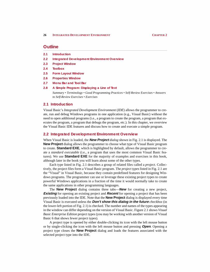
2.3 Project WindowThe window titled Project - Project1 (Fig. 2.3) is called the Project Explorer and con-tains the project files. We refer to the Project Explorer window simply as the Projectwindow.
The Project window’s tool bar contains three buttons, namely View Code , ViewObject and Toggle Folders . When pressed, the View Code button displays a windowfor writing Visual Basic code. Writing code is the main subject of this book. View Object ,when pressed, displays the form. Double-clicking Form1 (Form1) also displays the form.Both View Code and View Object are initially disabled (i.e., the buttons appear gray and
Title barMenu bar Tool barToolbox Form
CHAPTER 2 INTEGRATED DEVELOPMENT ENVIRONMENT 29
pressing them has no effect) unless Form1 (Form1) is selected (i.e., highlighted) as it isin Fig. 2.3. Figure 2.4 shows both the View Code and View Object buttons disabled. TheToggle Folders button toggles (i.e., alternately hides or shows) the Forms folder. Whenshown as in Fig. 2.3, the folder is visible, and when hidden as in Fig. 2.4, the folder is invis-ible. The Forms folder contains a listing of all forms in the current project. Early in thebook our projects will have only one form.
Later in this chapter we will save projects and forms with more meaningful names. Thecurrent names Project1 , Form1 , etc. are default names provided by Visual Basic to helpyou get started. Visual Basic does many things automatically to minimize the amount ofwork you must do to create applications. In this regard, Visual Basic is the world’s mostpopular RAD (Rapid Applications Development) programming language. The Projectwindow becomes an important project management tool as projects become more complex(i.e., contain more forms and other support files).
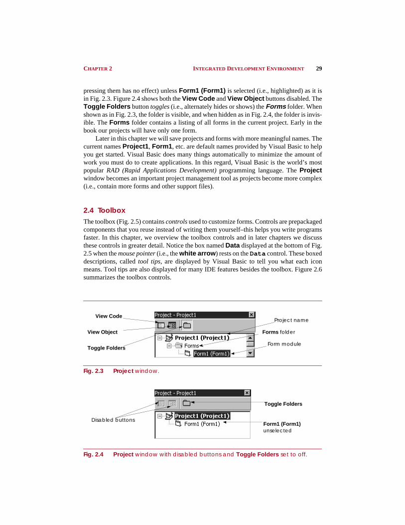
2.4 ToolboxThe toolbox (Fig. 2.5) contains controls used to customize forms. Controls are prepackagedcomponents that you reuse instead of writing them yourself–this helps you write programsfaster. In this chapter, we overview the toolbox controls and in later chapters we discussthese controls in greater detail. Notice the box named Data displayed at the bottom of Fig.2.5 when the mouse pointer (i.e., the white arrow ) rests on the Data control. These boxeddescriptions, called tool tips, are displayed by Visual Basic to tell you what each iconmeans. Tool tips are also displayed for many IDE features besides the toolbox. Figure 2.6summarizes the toolbox controls.
Fig. 2.3 Project window.
Fig. 2.4 Project window with disabled buttons and Toggle Folders set to off.
Project name
Forms folder
Form module
View Code
View Object
Toggle Folders
Toggle Folders
Form1 (Form1) unselected
Disabled buttons
30 INTEGRATED DEVELOPMENT ENVIRONMENT CHAPTER 2
Fig. 2.5 Toolbox window.
Control Description
Pointer Used to interact with the controls on the form (i.e., resize them, move them, etc.). The pointer is not a control.
PictureBox A control that displays images.
Label A control that displays uneditable text to the user.
TextBox A control for accepting user input. TextBox es can also display text.
Frame A control for grouping other controls.
CommandButton A control that represents a button. The user presses or clicks to initiate an action.
CheckBox A control that provides the user with a toggle choice (checked or unchecked).
OptionButton A “radio button.” OptionButtons are used in groups where only one at a time can be True (i.e., on)—like the buttons on a car radio.
ListBox A control that provides a list of items.
ComboBox A control that provides a short list of items.
Fig. 2.6 Toolbox control summary (part 1 of 2).
ListBox
OptionButton
CommandButton
TextBox
PictureBox
VScrollBar
DriveListBox
Tool tip
Line
Data
FileListBox
Pointer (not a control)
Frame
CheckBox
HScrollBar
Label
Timer
ComboBox
DirListBox
Shape
Image
OLE

CHAPTER 2 INTEGRATED DEVELOPMENT ENVIRONMENT 31
2.5 Form Layout WindowThe Form Layout window (Fig. 2.7) specifies a form’s position on the screen at runtime.The Form Layout window consists of an image representing the screen and the form’srelative position on the screen. With the mouse pointer positioned over the form image,drag (i.e., hold down the left mouse button, then move the mouse and release the button)the form to a new location. Note that the mouse pointer changes shape when over the imagerepresenting the form. Later in the book we discuss the various shapes that the mouse point-er can assume.
2.6 Properties WindowThe Properties window (Fig. 2.8) displays the properties for a form or control. Propertiesare attributes such as size, position, etc. Like a form, each control type has its own set ofproperties. Some properties, like Width and Height , such as, are common to both formsand controls, while other properties are unique to a form or control. Controls often differ inthe number and type of properties.
Fig. 2.7 Form Layout window.
HScrollBar A horizontal scrollbar.
VScrollBar A vertical scrollbar.
Timer A control that performs a task at programmer-specified intervals. A Timer is not visible to the user.
DriveListBox A control for accessing the system disk drives (C: , A: , etc.).
DirListBox A control for accessing directories on a system.
FileListBox A control for accessing files in a directory.
Shape A control for drawing circles, rectangles, squares or ellipses.
Line A control for drawing lines.
Image A control for displaying images. The Image control does not provide as many capabilities as a PictureBox .
Data A control for connecting to a database.
OLE A control for interacting with other window applications.
Control Description
Fig. 2.6 Toolbox control summary (part 2 of 2).
Screen
Mouse pointer
Form

32 INTEGRATED DEVELOPMENT ENVIRONMENT CHAPTER 2
Fig. 2.8 Properties window with the Alphabetic and Categorized tabs.
Properties are listed either alphabetically (by selecting the Alphabetic tab) or cate-gorically (by selecting the Categorized tab). Alphabetic lists the properties in alphabet-ical order and is the default. Clicking the Categorized tab lists properties by categories,such as Appearance , Behavior , DDE, Font , Misc , etc. The scrollbar can be used toscroll through the list of properties (by dragging the scrollbar up or down). We discuss set-ting individual properties later in this chapter and throughout the book.
2.7 Menu Bar and Tool BarCommands for developing, maintaining and executing programs are contained in the IDE’smenus. Figure 2.9 shows the menus displayed on the menu bar for a Standard EXEproject. Menus contain groups of related capabilities from which the user may select appro-priate choices. The menus of Fig. 2.9 are summarized in Fig. 2.10. Note: Your version ofVisual Basic may not have some of these menus.
Fig. 2.9 IDE menu bar.
Selected proper-ty description
Selected property
Name of control or form (Form1 )
Type of control or form (Form)
Scrollbar

CHAPTER 2 INTEGRATED DEVELOPMENT ENVIRONMENT 33
Rather than having to navigate the menus for certain commonly used commands, theprogrammer can select them from the tool bar (Fig. 2.11). The tool bar is comprised of pic-tures called icons that represent commands. Figure 2.11 shows the standard tool bar (i.e.,the default tool bar). The figure indicates which menus contain the equivalent commandsand it shows a few specific icons related to displaying the IDE windows.
2.8 A Simple Program: Displaying a Line of Text
In this section, we will create a program that displays the text “Welcome to Visual Ba-sic! ” on the form. The program consists of one form and uses one Label control to dis-play the text. The program is a Standard EXE. We do not write a single line of programcode. Instead, we introduce the techniques of visual programming in which through vari-ous programmer gestures (such as using the mouse for pointing, clicking, dragging and
Menu Description
File Contains options for opening projects, closing projects, printing projects, etc.
Edit Contains options such as cut, paste, find, undo, delete, etc.
View Contains options for displaying IDE windows and tool bars.
Project Contains options for adding features such as forms to the project.
Format Contains options for aligning and locking a form’s controls.
Debug Contains options for debugging.
Run Contains options for executing a program, stopping a program, etc.
Query Contains options for manipulating data retrieved from a database.
Diagram Contains options for editing and viewing the design of databases.
Tools Contains options for IDE tools and options for customizing the environment.
Add-Ins Contains options for using, installing and removing add-ins. Add-ins are typically independent software vendor (ISV) products that extend Visual Basic’s features.
Windows Contains options for arranging and displaying windows.
Help Contains options for getting help.
Fig. 2.10 Menu summary.
Edit iconsFile icons Run icons View iconsProject icons
Project explorer (Project window)
Properties window
Form Layout window
ToolboxTools icon
Fig. 2.11 Tool bar icons.

34 INTEGRATED DEVELOPMENT ENVIRONMENT CHAPTER 2
dropping) we provide Visual Basic with sufficient information so that it can automaticallygenerate all or a major portion of the program code for our program. Figure 2.12 showsthe program at runtime. In the next chapter, we begin our discussion of writing programcode. Throughout the book we will produce increasingly substantial and powerful pro-grams. Visual Basic programming involves a combination of writing a portion of the pro-gram code yourself and having Visual Basic generate the remaining code automatically.
Here are the steps you perform to create, run and terminate this first program:
1. Setting the form’s title bar. The form’s Caption property determines what isdisplayed in the form’s title bar. In the Properties window, set the Captionproperty to Fig. 2.12: A Simple Program . To change the value of thisproperty, click in the field next to Caption (this field displays Form1 ). Deletethe existing value using the Backspace key or Delete key and enter the new value.Hit the Enter key (Return key). Note: As you enter a new value for the Captionproperty the form’s title bar changes in response to what you are typing.
2. Setting the form’s Name property. The Name property identifies a form or control.Set the Name property to frmFig02_12 . After the property is set, note thechanges to the Properties window and Project window as shown in Fig. 2.13.
Fig. 2.12 Program at run-time.
Fig. 2.13 Properties window and Project window after the Name property is set.
Title bar
Properties window and Project window areas where the form’s Name is displayed

CHAPTER 2 INTEGRATED DEVELOPMENT ENVIRONMENT 35
Good Programming Practice 2.1
Prefix the Name of each form with frm to make form objects easy to identify. 2.1
3. Resizing the form. Click and drag one of the form’s enabled sizing handles (thesmall squares around the form shown in Fig. 2.14). White sizing handles are dis-abled and the programmer cannot use them to resize the form. Sizing handles thatare black are enabled and can be used for resizing. Size the form according to yourown preference. Sizing handles are not visible during program execution.
4. Centering the form. Center the form using the Form Layout window (Fig. 2.15).This causes the form to display in the center of the monitor when the program isexecuted.
Fig. 2.14 Form with sizing handles.
Fig. 2.15 Form Layout window with form centered.
Grid
Title bar
Disabled sizing handle
Enabled sizing handle
Screen
Form

36 INTEGRATED DEVELOPMENT ENVIRONMENT CHAPTER 2
5. Changing the form’s background color. The BackColor property specifies aform or control’s background color. Clicking BackColor in the Propertieswindow causes a down-arrow button to appear next to the property value as shownin Fig. 2.16. When clicked, the down arrow displays a window with the tabs Sys-tem (the default) and Palette . Click the Palette tab to display the palette (agroup of colors from which the user selects one by clicking). Select the box rep-resenting yellow. The palette disappears and the form’s background color changesto yellow. Note that BackColor displays a small rectangle representing the cur-rent color.
6. Adding a Label control to the form. Double-click the toolbox's Label controlto create a Label with sizing handles in the center of the form (Fig. 2.17). TheLabel displays the word Label1 by default. Double clicking any toolbox con-trol results in a control being created and placed in the center of the form. Whenthe sizing handles appear around the Label , the Properties window displaysthe Label ’s properties. Clicking the form causes the form’s properties to be dis-played in the Properties window.
7. Setting the Label ’s display. The Label ’s Caption property determines whattext (if any) the Label displays. The form and Label each have their own Cap-tion property—with each being completely independent of the other. Forms andcontrols can have properties with the same name without conflict. Set the La-bel ’s Caption property to Welcome to Visual Basic! (Fig. 2.18). TheLabel displays each character as it is typed. Note that when the edge of the La-bel is reached, the text automatically wraps to the next line.
Fig. 2.16 Changing the BackColor .
Current color
Down arrow
The color yellow

CHAPTER 2 INTEGRATED DEVELOPMENT ENVIRONMENT 37
Fig. 2.17 A Label placed on the form.
Fig. 2.18 The Caption property set for the Label .
8. Naming the Label . The Label ’s Name property is used to identify the Label .The default name for the Label we just created is Label1 . Set the Name prop-erty to lblWelcome .
Good Programming Practice 2.2
Prefix the Name of each Label with lbl to make Label objects easy to identify. 2.2
Good Programming Practice 2.3
Following widely accepted naming conventions can make your program clearer—especiallyto other people. 2.3
Label control icon
Label created by double clicking Label control
Sizing handle

38 INTEGRATED DEVELOPMENT ENVIRONMENT CHAPTER 2
9. Customizing the Label ’s colors. Like a form, a control’s BackColor is gray bydefault, and we wish to change it to yellow. There are two ways to accomplish thisusing the Label ’s properties. One way is to change the Label ’s BackColorproperty to yellow—which works well as long as the form’s BackColor doesnot change. If the form’s BackColor changes, the Label BackColor re-mains yellow. The second way is to change the Label ’s BackStyle propertyfrom Opaque (i.e., solid) to Transparent (i.e., see through). The Label ’sForeColor property determines the color in which text is displayed. Set theForeColor to blue using the techniques discussed in Step 5.
10. Setting the Label ’s font size and aligning the Label ’s text. Clicking the Fontproperty value causes an ellipsis button to appear (Fig. 2.20). When this button ispressed, the Font window of Fig. 2.21 appears. The font name (MS Sans Serif ,Serif , etc.), font style (Regular , Bold , etc.) and font size (8, 10, etc.) can be se-lected. The current font is applied to the text in the Sample area. Under the Sizecategory select 24 and press OK. Next, select the Alignment property—whichdetermines how the text is aligned within the Label boundaries. The threeAlignment choices are Left Justify (the default), Right Justify andCenter . Select Center . At this point, you might notice that the Label size istoo small for the font size. In the next step we will resize the Label .
11. Positioning and resizing the Label . Resize the Label using the Label ’s sizinghandles, such that the Label appears similar to that of Fig. 2.22. Note the changein the mouse pointer when it is placed over a sizing handle. Center the Label onthe form by dragging the Label . The grid dots on the background of the form areused for aligning controls and are only visible at design time.
Fig. 2.19 Transparent Label with yellow ForeColor .

CHAPTER 2 INTEGRATED DEVELOPMENT ENVIRONMENT 39
Fig. 2.20 Properties window displaying the Label ’s properties.
Fig. 2.21 Font window for selecting fonts, styles and sizes.
Fig. 2.22 Resizing the Label .
Ellipsis button
Sample of current font applied
Current selections
Mouse pointer
Sizing handle
Grid

40 INTEGRATED DEVELOPMENT ENVIRONMENT CHAPTER 2
12. Saving the project. Click the Save Project tool bar icon (Fig. 2.23) or selectSave Project / Save Project As... from the File menu to display the SaveFile As... dialog (Fig. 2.23). The Save File As... dialog specifies the form filename that will store all the form’s information (i.e., properties, etc.). We save ourfile in the c:\books\vbhtp\examples\chap02\fig02_12 directory. You arefree to choose whatever directory you want. The window provides the capabilitiesto visually navigate the directories and to create new folders. After specifying thename and directory, click the Save button.
The next dialog that appears is the Save Project As... dialog. The features of thisdialog are identical to the features of the Save File As... dialog, except that now wespecify the project file name. The project file stores the name and location of every file inthe project. We save the project in the same directory as the form(c:\books\vbhtp\examples\chap02\fig02_12 ). Again you are free to save the projectfile in any directory you choose. Figure 2.25 shows the Project window after the projectis saved.
13. Running the program. Prior to this step, we have been working in the IDE designmode (i.e., the program is not executing). While in design mode, the programmerhas access to all the environment windows (i.e., toolbox and Properties ), menus,tool bars, etc. While in run mode the program is executing and the user can onlyinteract with a few IDE features. Features that are not available are disabled. Toexecute or run your program, click the Start button or select Start from the Runmenu. Figure 2.26 shows the IDE in run mode. Note that the IDE title bar displays[Run] and that most tool bar icons are disabled. Also note that the Immediatewindow appears at runtime. The Immediate window is primarily used for debug-ging (i.e., removing errors from your program) and is discussed in Chapter 13.
Fig. 2.23 Save File As... dialog.
Save Project tool bar icon
Current directory New folderUp one directory level
Contents of current directory
Save file as

CHAPTER 2 INTEGRATED DEVELOPMENT ENVIRONMENT 41
Fig. 2.24 Save Project As... dialog.
Fig. 2.25 Project window after saving project.
Fig. 2.26 IDE during execution.
Project file name
Form file name
Project name
Form name
Project window
Close button
Immediate window
End button
Form
Start buttonRun-mode
42 INTEGRATED DEVELOPMENT ENVIRONMENT CHAPTER 2
14. Terminating execution. Clicking form’s Close button icon (i.e., the “X” at the topright corner of Fig. 2.26) or by clicking the tool bar’s End button terminates pro-gram execution and places the IDE in design mode.
Summary• The Visual Basic Integrated Development Environment (IDE) allows the programmer to create,
run and debug Windows programs.
• The New Project dialog allows the programmer to choose what type of Visual Basic program tocreate. Standard EXE allows the programmer to create a standard executable (i.e., a program thatuses the most common Visual Basic features).
• The New Project dialog contains three tabs—New for creating a new project, Existing foropening an existing project and Recent for opening a project that has been previously loaded intothe IDE.
• We refer to single clicking with the left mouse button as selecting or clicking, and we refer to dou-ble-clicking with the left mouse button simply as double-clicking.
• A Standard EXE project contains the following windows: Project1 - Form1 (Form ), FormLayout, Properties - Form1, Project - Project1 and the toolbox.
• The Project - Form1 (Form ) window contains a child window named Form1 , which is wherethe program’s Graphical User Interface (GUI) will be displayed. A GUI is the visual portion of theprogram (i.e., buttons, checkboxes, etc.)–this is where the user enters data (called inputs) to theprogram and where the program displays its results (called outputs) for the user to read.
• The Form Layout window enables the user to specify the form’s position on the screen when theprogram is executed.
• The Properties - Form1 window displays form attributes or properties (i.e., color, font style,size, etc.).
• The toolbox contains controls for customizing the GUI (i.e., the form). Controls are GUI compo-nents such as buttons and checkboxes.
• The window titled Project - Project1 (Fig. 2.3) is called the Project Explorer and containsthe project files. We refer to the Project Explorer window simply as the Project window.
• The Project window’s tool bar contains three buttons, namely View Code , View Object andToggle Folders . When pressed, the View Code button displays a window for writing VisualBasic code.
• View Object , when pressed, displays the form. Double-clicking Form1 (Form1) also displaysthe form.
• Both View Code and View Object are initially disabled (i.e., the buttons appear gray and press-ing them has no affect) unless Form1 (Form1) is selected (i.e., highlighted).
• The Toggle Folders button toggles (i.e., alternately hides or shows) the Forms folder.
• The Forms folder contains a listing of all forms in the current project.
• Visual Basic does many things automatically to minimize the amount of work you must do to cre-ate applications. In this regard, Visual Basic is the world’s most popular RAD (Rapid ApplicationsDevelopment) programming language.
• The Project window becomes an important project management tool as projects become morecomplex (i.e., contain more forms and other support files).
• The toolbox contains controls used to customize forms. Controls are prepackaged components thatyou reuse instead of writing them yourself–this helps you write programs faster.

CHAPTER 2 INTEGRATED DEVELOPMENT ENVIRONMENT 43
• Tool tips are displayed by Visual Basic to tell you what each icon means.
• The pointer is used to interact with the controls on the form (i.e., resize them, move them, etc.).The pointer is not a control.
• A PictureBox is a control that displays images.
• A Label is a control that displays uneditable text to the user.
• A TextBox is a control for accepting user input. TextBox es can also display text.
• A Frame is a control for grouping other controls.
• A CheckBox is a control that provides the user with a toggle choice (checked or unchecked).
• An OptionButton is a “radio button.” OptionButtons are used in groups where only oneat a time can be True (i.e., on), just like the buttons on a car radio.
• ListBox is a control that provides a list of items.
• A ComboBox is a control that provides a short list of items.
• An HScrollBar is a horizontal scrollbar.
• A VScrollBar is a vertical scrollbar.
• A Timer is a control that performs a task at programmer-specified intervals. A Timer is not vis-ible to the user.
• A DriveListBox is a control for accessing the system disk drives (C: , A: , etc.).
• A DirListBox is a control for accessing directories on a system.
• A FileListBox is a control for accessing files in a directory.
• A Shape is a control for drawing circles, rectangles, squares or ellipses.
• A Line is a control for drawing lines.
• An Image is a control for displaying images. The Image control does not provide as many ca-pabilities as a PictureBox .
• A Data control provides a means for connecting to a database.
• An OLE control for interacting with other Windows applications.
• The Form Layout window specifies a form’s position on the screen at run-time. The Form Lay-out window consists of an image representing the screen and the form’s relative position on thescreen. To reposition the form on the screen, position the mouse pointer over the form image, thendrag (i.e., hold down the left mouse button, then move the mouse and release the button) the formto a new location.
• The Properties window displays the properties for a forms and controls.
• Properties are attributes such as size, position, etc. Like a form, each control type has its own setof properties. Some properties, such as, Width and Height , are common to both forms and con-trols, while other properties are unique to a form or control. Controls often differ in the numberand type of properties.
• Properties are listed either alphabetically (by selecting the Alphabetic tab) or categorically (byselecting the Categorized tab). Alphabetic lists the properties in alphabetical order and is thedefault. Clicking the Categorized tab lists properties by categories, such as Appearance , Be-havior , DDE, Font , Misc , etc. The scrollbar can be used to scroll through the list of properties(by dragging the scrollbar up or down).
• Commands for developing, maintaining and executing programs are contained in the IDE’smenus. Menus contain groups of related capabilities from which the user may select appropriatechoices.

44 INTEGRATED DEVELOPMENT ENVIRONMENT CHAPTER 2
• The File menu contains options for opening projects, closing projects, printing projects, etc.
• The Edit menu contains options such as cut, paste, find, undo, delete, etc.
• The View menu contains options for displaying IDE windows and tool bars.
• The Project menu contains options for adding features such as forms to the project.
• The Format menu contains options for aligning and locking a form’s controls.
• The Debug menu contains options for debugging.
• The Run menu contains options for executing a program, stopping a program, etc.
• The Query menu contains options for manipulating data retrieved from a database.
• The Diagram menu contains options for editing and viewing the design of databases.
• The Tools menu contains options for IDE tools and options for customizing the environment.
• The Add-Ins menu contains options for using, installing and removing add-ins. Add-ins are typ-ically independent software vendor (ISV) products that extend the features of Visual Basic.
• The Windows menu contains options for arranging and displaying windows.
• The Help menu contains options for getting help.
• Rather navigating the menus for certain commonly used commands, the programmer can selectthem from the tool bar. The tool bar is comprised of pictures called icons that represent commands.
• We do not write a single line of code—instead, we introduce the technique of visual programming.
• The form’s Caption property determines what is displayed in the form’s title bar.
• To change the value of the Caption property, click in the field next to Caption . Delete the ex-isting value using the Backspace key or Delete key and enter the new value. Hit the Enter key (Re-turn key). As you enter a new value for the Caption property the form’s title bar changes inresponse to what you are typing.
• The Name property identifies a form or control.
• To resize a form, click and drag one of the form’s enabled sizing handles (the small squares aroundthe form). White sizing handles are disabled and the programmer cannot use them to resize theform. Sizing handles that are black are enabled and can be used for resizing. Sizing handles arenot visible during program execution.
• A form can be centered by using the Form Layout window.
• The BackColor property specifies a form or control’s background color. Clicking BackColorin the Properties window causes a down-arrow button to appear next to the property value.When clicked, the down arrow displays a window with the tabs System (the default) and Pal-ette . Click the Palette tab to display the palette (a group of colors from which the user selectsone by clicking). The BackColor displays a small rectangle representing the current color.
• To add a Label control to a form, double-click the toolbox's Label control to create a Labelwith sizing handles in the center of the form. The Label displays the word Label1 by default.Double-clicking any toolbox control results in a control being created and placed in the center ofthe form. When the sizing handles appear around the Label , the Properties window displaysthe Label properties. Clicking the form causes the form’s properties to be displayed in the Prop-erties window.
• The Label ’s Caption property determines what text (if any) the Label displays. The form andLabel each have their own Caption property—with each being completely independent of theother. Forms and controls can have properties with the same name without conflict. The Labeldisplays each character as it is typed. Note that when the edge of the Label is reached, the textautomatically wraps to the next line.

CHAPTER 2 INTEGRATED DEVELOPMENT ENVIRONMENT 45
• A control’s BackColor is gray by default.
• A Label has a BackColor property. A Label ’s BackStyle property can be Opaque (i.e.,solid) or Transparent (i.e., see through).
• A Label ’s ForeColor property determines the color in which text is displayed.
• Clicking a Label ’s Font property value causes an ellipsis button to appear. When this button ispressed, the Font dialog appears. The font name (MS Sans Serif , Serif , etc.), font style (Reg-ular , Bold , etc.) and font size (8, 10, etc.) can be selected. The current font is applied to the textin the Sample area.
• A Label ’s Alignment property determines how text is aligned within the Label boundaries.The three Alignment choices are Left Justify (the default), Right Justify and Cen-ter .
• A Label can be resized using its sizing handles. The shape of the mouse pointer changes whenit is placed over a sizing handle. The grid dots on the background of the form are used for aligningcontrols at design time.
• Click the Save Project tool bar icon or select Save Project / Save Project As... from the Filemenu to display the Save File As... dialog. The Save File As... dialog specifies the form filename that will store all the form’s information (i.e., properties, etc.) as well as its directory loca-tion.
• The Save Project As... dialog’s features are identical to those of the Save File As... dialog,except that you use it to specify the project file name. The project file stores the name and locationof every file in the project.
• In IDE design mode, the program is not executing. While in design mode, the programmer has ac-cess to all the environment windows (i.e.f, toolbox and Properties , menus, tool bars, etc.).
• While in run mode the program is executing and the user can interact with only a few IDE features.Features that are not available are disabled.
• To execute or run a program, click the Start button or select Start from the Run menu. Note thatthe IDE title bar displays [Run] and that most tool bar icons are disabled. Also note that the Im-mediate window appears at run-time. The Immediate window is primarily used for debugging.
• Clicking form’s Close button icon (i.e., the “X” at the form’s top-right corner or clicking the toolbar’s End button terminates program execution and places the IDE in design mode.
Terminologyactive window checkboxAdd-Ins menu click and dragAlignment property of a Label clickingAlignment property’s Left Justify value Close buttonAlignment property’s Right Justify value controlsAlphabetic tab of Properties window Debug menuBackColor property of a Form Delete keyBackspace key design modeBackStyle property design timebutton disabled buttonCancel button disabled sizing handleCaption property Don’t show this dialog in the futureCategorized tab of a Properties window double-clickingCenter value of Alignment property down-arrow button
46 INTEGRATED DEVELOPMENT ENVIRONMENT CHAPTER 2
Good Programming Practices2.1 Prefix the Name of each form with frm to make form objects easy to identify.2.2 Prefix the Name of each Label with lbl to make Label objects easy to identify.2.3 Following widely accepted naming conventions can make your program clearer—especially
to other people.
Self-Review Exercises2.1 Fill in the blanks in each of the following:
a) A is a customizable window.
dragging Project windowEdit menu propertiesellipsis button Properties windowenabled sizing handle RAD (Rapid Applications Development)End button radio buttonsEnter key Recent tab of New Project dialogEnterprise Edition Return keyExisting tab of New Project dialog Run menuFile menu run modefocus run-timefont Sample area of Font windowFont property of a Label Save buttonFont window Save File As... dialogForeColor property of a Label Save Project As... dialogform Save Project tool bar iconFormat menu selectingForm Layout window sizing handleForms folder Standard EXE project typegraphical user interface (GUI) standard executablegrid standard tool barHeight property standard Visual Basic executableHelp menu Start buttonicons System tabImmediate window title barintegrated development environment (IDE) toggleLabel control Toggle Folders button in Project windowmenu tool barmenu bar toolboxmouse pointer Toolbox windowName property Tools menuNew Project dialog tool tipsNew tab of New Project dialog Transparent valueOpaque value of Back Style property VB Application Wizard project typeOpen button VB Learning Edition Controls project typepalette of colors View Code button in Project windowPalette tab View menuproject View Objects button in Project windowProject Explorer window visual programmingProject menu Width propertyproject types Window menu

CHAPTER 2 INTEGRATED DEVELOPMENT ENVIRONMENT 47
b) The form’s is used to visually align controls.c) The form’s property specifies the text for the form’s title bar.d) The window has a dark-colored title bar and is said to have the .e) The window determines where a form will appear on the screen at execution.f) The window contains the program files.
2.2 State whether each of the following is true or false. If false, explain why.a) The tool bar contains the control icons.b) The Project window is also called the Project Explorer .c) The tool bar provides a convenient way to execute certain menu commands.d) The Properties window is also called the Immediate window.e) A form’s sizing handles are always enabled.f) The pointer is not a control.
2.3 Match the control name with the proper toolbox icon in Fig. 2.27. Note that OLE is notshown.
Fig. 2.27 Toolbox.
Answers to Self-Review Exercises2.1 a) form. b) grid. c) Caption . d) active, focus. e) Form Layout . f) Project orProject Explorer .
2.2 a) False. The toolbox contains the control icons.b) True.c) True.d) False. The Immediate window is a distinctly different window.e) False. Some of the form’s sizing handles are disabled.f) True.
a) CommandButton k) TextBoxb) OptionButton l) HScrollBar (Horizontal scrollbar)c) Label m) DriveListBoxd) Line n) Shapee) Frame o) CheckBoxf) Image p) Datag) PictureBox q) FileListBoxh) VScrollBar (Vertical scrollbar) r) ListBoxi) Pointer s) Timerj) ComboBox t) DirListBox (Directory list box)
1
11
10
20
12
92 3 4 5 6 7 8
13 14 15 16 17 18 19
48 INTEGRATED DEVELOPMENT ENVIRONMENT CHAPTER 2
2.3 a) 6. b) 8. c) 3. d) 18. e) 5. f) 19. g) 2. h) 12. i) 1. j) 9. k) 4. l) 11. m) 14. n) 17. o) 7.p) 20. q) 16. r) 10. s) 13. t) 15.
Exercises2.4 Fill in the blanks in each of the following statements:
a) The contains a variety of colors, from which the programmer selects one.b) The three values of the Alignment property are , and .c) The property changes a control’s foreground color.d) IDE is an abbreviation for .e) Clicking the on the toolbar executes the program.f) The property identifies a form and is often prefixed with frm . g) GUI is an abbreviation for .h) A is a group of related files.
2.5 State which of the following are true and which are false. If false, explain why.a) At run-time, a form’s grid is visible.b) A tool tip identifies an IDE feature.c) A Label ’s Text property determines what text is displayed to the user.d) At design-time, almost every IDE feature is available.e) When placed over an enabled sizing handle, the mouse pointer changes.f) A Label displays uneditable text to the user.g) A form and Label have an identical set of properties.
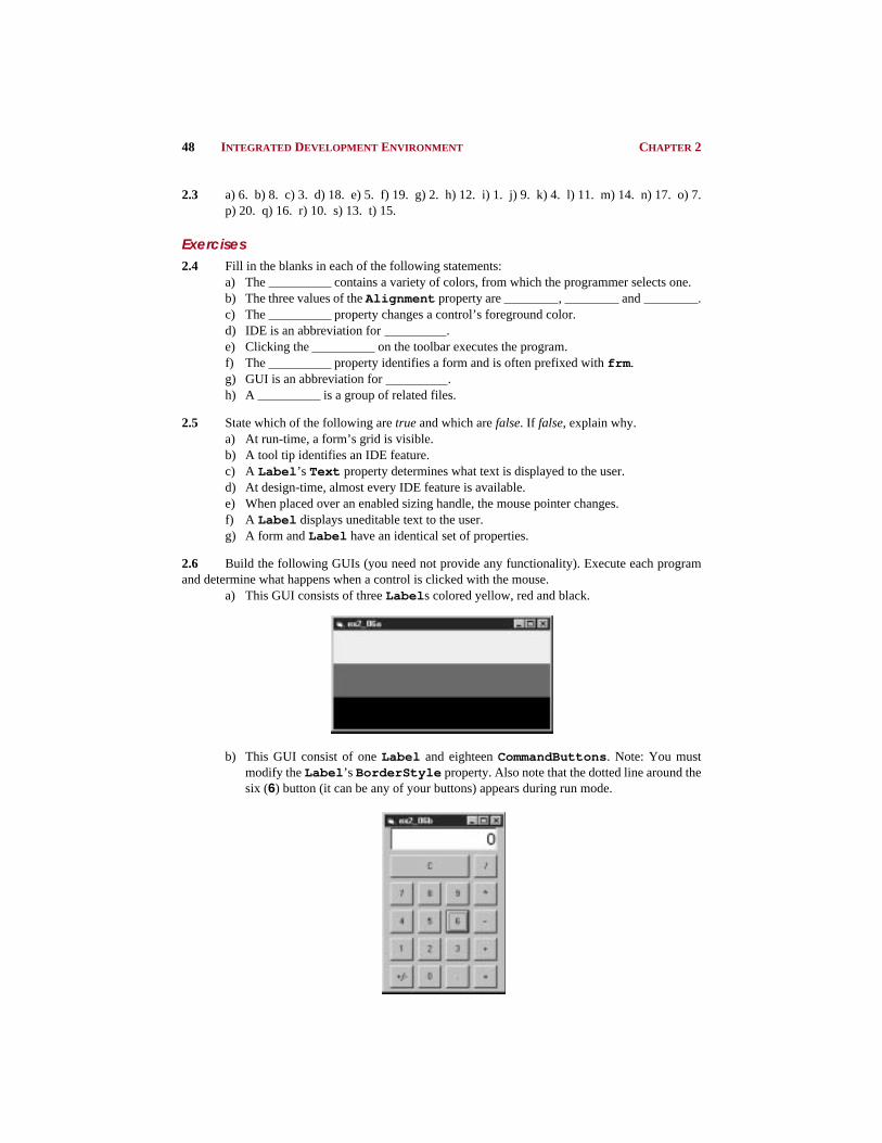
2.6 Build the following GUIs (you need not provide any functionality). Execute each programand determine what happens when a control is clicked with the mouse.
a) This GUI consists of three Label s colored yellow, red and black.
b) This GUI consist of one Label and eighteen CommandButtons . Note: You mustmodify the Label ’s BorderStyle property. Also note that the dotted line around thesix (6) button (it can be any of your buttons) appears during run mode.

CHAPTER 2 INTEGRATED DEVELOPMENT ENVIRONMENT 49
c) The following GUI consists of one Label , one CommandButton and four Option-Button s. Note: The black dot in Dog automatically appears at run-time but may appearin a different one of your buttons.
d) The following GUI consists of three VScrollBar s and two Label s. Note: One La-bel requires its BorderStyle property changed. Also note that one VScrollBar ’sscroll box automatically flashes at run-time.
2.7 Briefly describe each of the following IDE features:a) tool barb) menu barc) toolboxd) controle) formf) projectg) title bar
2.8 Briefly describe the differences between design mode and run mode.
2.9 Compare a form’s properties to a Label ’s properties. Make a list of all the properties that are commonto both. Now, summarize only the properties on the list we have discussed in this chapter.
2.10 Why do you think that the toolbox, the form and the Properties window are crucial to theconcept of visual programming?
Flashing scroll box

50 INTEGRATED DEVELOPMENT ENVIRONMENT CHAPTER 2