Integrated Applications of Fiber-Optic Distributed ... · Integrated Applications of Fiber-Optic...
15
Integrated Applications of Fiber-Optic Distributed Acoustic and Temperature Sensing Francisco Porturas, Ziebel, Norway
Transcript of Integrated Applications of Fiber-Optic Distributed ... · Integrated Applications of Fiber-Optic...

Integrated Applications of Fiber-Optic Distributed Acoustic and Temperature
Sensing
Francisco Porturas, Ziebel, Norway

Contents
• Fiber-optic DTS and DAS principles
• Fiber-optic DTS and DAS Field Operations and Data management
• DTS and DAS current applications worldwide
• Summary
• Acknowledgements

Fiber-optic DTS and DAS principles
Raman and Rayleigh scattering peaks as function of the intensity, classic DTS measurement principle (the figure is not in scale).
Fiber-optic DTS and DAS principles
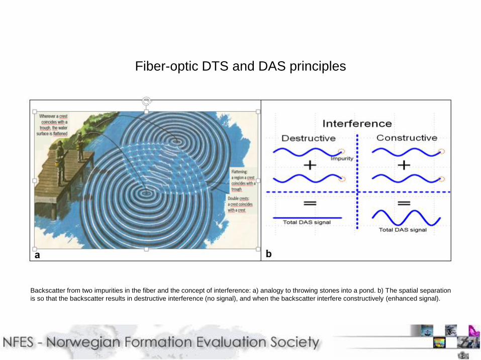
Backscatter from two impurities in the fiber and the concept of interference: a) analogy to throwing stones into a pond. b) The spatial separation
is so that the backscatter results in destructive interference (no signal), and when the backscatter interfere constructively (enhanced signal).
Multi-mode fiber
T1
T2
T3
T4
T1000
T1001
T1003
T10041m long pulse
Measurement point every ~0.5m
Fiber-optic DTS principles
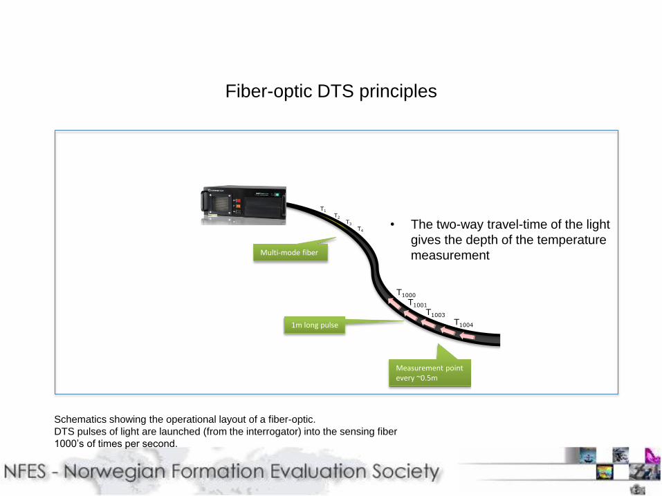
• The two-way travel-time of the light
gives the depth of the temperature
measurement
Schematics showing the operational layout of a fiber-optic.
DTS pulses of light are launched (from the interrogator) into the sensing fiber
1000’s of times per second.

Single-mode fiber
T1
T2
T3
T4
T1000
T1001
T1003
T10041-10m long pulse
Measurement point every ~0.67m
Fiber-optic DAS principles
• The two-way travel-time of the light
gives the depth of the acoustic
measurement
DAS acquisition interaction between the interrogator and the fiber itself. Pulses of light are
launched (from the interrogator) into the sensing fiber 5,000 or 15,000 of times per second.
Data size recorded will depend on the sensing program objectives, target depth and recording
time (duration of each phase).

Fiber-optic DTS and DAS Field Operations: Sensing Program

Fiber-optic DTS and DAS Field Operations
Field acquisition units. a) Offshore lay-out, showing the sensing components for a gravity deployed fiber-optic DTS DAS field operation unit, here fiber optic
contains six fiberoptical cables, bottom hole assembly (BHA), BOP contro. b) On-shore standalone field acquisition unit, similar modules in one 20-ton
mobile unit. Similar layout for a semi-stiff carbon road (Z-Rod) fiber-optic system.

Fiber-optic DAS Feature Highlight Techniques
Feature highlighting techniques, showing only a
partial set out of a multiple selection choices
offering a wide range of options to visualize DAS
processing results, band pass filtering, attribute
mapping, to enhanced DAS event identification,
observation, resolution and interpretation.

Fiber-optic DAS Feature Highlight Techniques: Frequency Filtering
Example of a real-time DAS image
and displayed after applying
frequency-filtering options.

DTS and DAS current applications worldwide: Injection and Production
DTS applications. a) Injection mode: DTS waterfall display showing an initial hot-slug as a function of time (1.5 hours). Improved DTS data allow for a fast analysis of injection
volumes and easy decision on injectivity performance at respective zone of interest. b) Production mode, a 4 hours production DTS data, showing the reservoirs interval, free gas
entry zones (cooling effect) and liquid entry, here the thermal zonation will allow for a fast turnaround flow allocation analysis.

DTS and DAS current applications worldwide: Production
a) DTS traces showing a temperature anomaly, cooling due to free gas, also the GLV location and its temperature response, and b) DAS image, free gas
flowing from the upper two sliding sleeves. c) Fiber-optic entered safely through a restriction where small ID wireline tools could not enter. The green lines
indicates the location of the perforations, d) DAS real time image showing the contributing perforations, and e) DTS waterfall display showing the water-
producing zone.
a b c d e
DTS and DAS current applications worldwide: Well Integrity
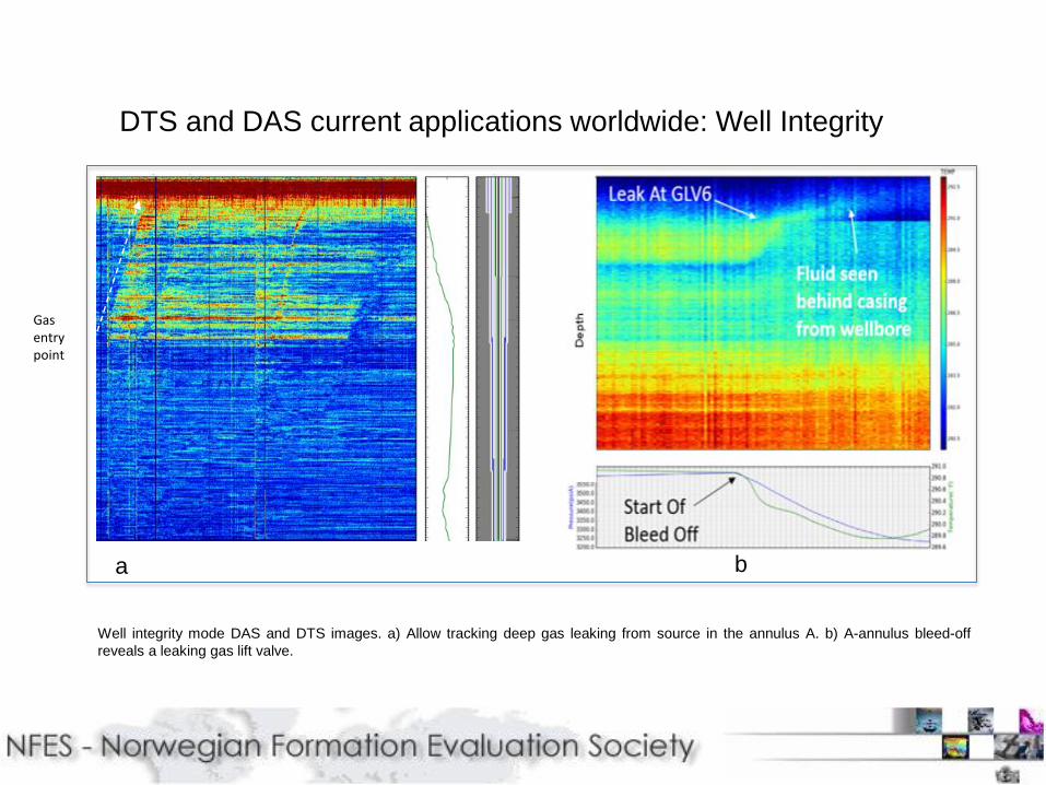
Well integrity mode DAS and DTS images. a) Allow tracking deep gas leaking from source in the annulus A. b) A-annulus bleed-off
reveals a leaking gas lift valve.
Gas entrypoint
a b

Fiber optic DTS and DAS technology offers solutions to acquire
enhanced data with applications to production flow, completion and
hydraulic fracture monitoring operations in real time during the asset
lifecycle.
The possibility of observing the entire wellbore simultaneously in real
time is providing the necessary information to learn more about for
instance leak behind casing and other integrity issues.
Summary
Acknowledgements
We would like to thank ConocoPhillips North Sea & USA, BP Norway,
Statoil Norway, Maersk Denmark, BHP Billiton USA, PDO Oman, Daleel
Oman, ADCO UAE, Marathon USA, and Asset Teams for an excellent
communication, transparency and cooperation and to Ziebel for a flawless
field operation and dedicated real-time reservoir support.
Slide 15